x-ray absorption and emission -...
TRANSCRIPT

X-ray Absorption and Emission Prepared By Jose Hodak for BSAC program 2008 1- A bit of History: Wilhelm Conrad Röntgen discovered 1895 the X-rays. 1901 he was honored by the Noble prize for physics. In 1995 the German Post edited a stamp, dedicated to W.C. Röntgen.
2- Generation of x-rays: A discharge in a low pressure gas causes electrons emitted by the filament to be accelerated from the cathode (-) to the anode (+). Electrons collide against the anode surface coming to a stop and all their kinetic energy is dissipated in the process. The final velocity of the electrons depends on the voltage difference between the cathode and the anode. In addition, because the electrons are charged, when they are accelerated or decelerated they produce electromagnetic radiation in a broad wavelength range covering from the ultraviolet up to the X-ray region. This decelerating process is called “Bremsstrahlung” (german fror slowing down).Figures 1 and 2 shows how the x-Rays are generated:
Figure 1: Schematic of an “x-ray tube”

Figure 2: x-ray emission by bremsstrahlung radiation. The incoming electron is scattered at different angles, therefore a component of acceleration acting in the direction perpendicular to the direction of propagation must exist. As a consequence, electromagnetic radiation is emitted. The bremsstrahlung radiation has a broad spectrum up to a maximum energy equivalent to the kinetic energy of the incoming electron, corresponding to complete stopping of the electron, with all its energy being converted to a single x-ray photon. The spectrum of this emission does not depend on the material of the anode. It only depends on the voltage applied to the tube. When this voltage is sufficiently large the kinetic energy of the electrons becomes comparable to the binding energy of the electros in the atoms of the anode. This is shown in Figure 3. When this occurs, the “vacancy” left by removal of one of the inner electrons constitutes an excited state of the atom. It follows that relaxation of an electron from a higher orbital can occur, and the energy difference between the upper-lower orbital appears in the form of an x-ray photon with a well defined wavelength. Since the energy differences between orbitals depends on Z, different elements emit x-ray photons with their characteristic wavelength. Thus this type of radiation receives the name of characteristic radiation.
Figure 3: Characteristic x-ray radiation
Initial models described the atoms as consisting of a nucleus surrounded by “shells” of electrons named from the nucleus outwards as K, L M and so on. Thus, since the electron is removed from the innermost shell (K), the radiation was named after the shell to which the electron relaxation takes place: if an electron

relaxes from any shell into the K shell we have K radiation. K-alpha is from the L to the K shell, K beta is from the M shell to the K shell and so on. Similarly for emission that occurs after relaxation into the L shell. Now we know that the different shells correspond to different principal quantum numbers n. And because there are sublevels for shells n larger than 1, there are several lines on each radiation. Figure 4 shows this.
Figure 4

Figure 5 Bremsstrahlung and characteristic x-Ray emission from Molibdenum.
Table 1: Examples of x-ray emission by various elements
For most practical purposes the continuum (bremsstrahlung) is not too useful, only the characteristic emission is used. Since each element emits its own characteristic x-rays, this has applications in analytical chemistry. All we have to do is to put the sample in a vacuum tube and expose it to high energy electrons. If we then measure the x-ray spectrum, we could se what elements are present in the sample. In practice this is not done in this way. 3-X-ray wavelength and energy scales The X-ray or Ro¨ntgen region of the electromagnetic spectrum starts at ca. 10 nm and extends towards the shorter wavelengths. The energies of X-ray photons are of the same order of magnitude as the binding levels of inner-shell electrons (K, L, M,… levels) and therefore can be used to excite and/or probe these atomic levels. The wavelength l of an X-ray photon is inversely related to its energy E according to:
1.240(nm)=E(keV)
λ
where 1 eV is the kinetic energy of an electron that has been accelerated over a voltage difference of 1 V 191 1.602 10eV J−= × . So the X-ray energy range starts at 100 eV and continues towards higher
energies. X-ray analysis methods most commonly employ radiation in the 1–50 keV (10–0.2Å ) range. The established unit of measure for wavelengths in the X-ray region is the angstrom; 1 Å is equal to 0.1nm. 4- Interaction of X-rays with matter When X-ray beam passes through matter, some photons will be absorbed inside the material or scattered away from the original path, as illustrated in Fig. 1. The intensity I0 of an X-ray beam passing through a layer of thickness d and ρ density is reduced to an intensity I according to the well-known law of Lambert–Beer:
0dI I e μρ−=

Fig. 1. X-ray scattering, absorption and fluorescence
Figure 7
The number of photons (the intensity) is reduced but their energy is generally unchanged. The term μ is
called the mass attenuation coefficient and has the dimension 2cm /g . The product lμ μρ= is called the
linear absorption coefficient and is expressed in -1cm . ( )Eμ is sometimes also called the total cross-section for X-ray absorption at energy E. Fig. 2 shows a log–log plot of the energy dependence of the mass attenuation coefficient of several chemical elements in the X-ray energy range between 1 and 100 keV. The absorption edge discontinuities are due to photoelectric absorption.
Figure 8.

Low Z materials attenuate X-rays of a given energy less than high-Z materials. A given material will attenuate high energy (i.e., hard) X-rays less than low energy (soft) X-rays. The mass absorption coefficient ( )Eμ of a complex mixture M consisting of several chemical elements (e.g., an alloy such as brass), can be calculated from the mass attenuation coefficient of the n constituting elements:
ii i i
1 1( ) w
n n
i i tot
mMm
μ μ μ= =
= =∑ ∑
where iμ mi is the mass attenuation coefficient of the ith pure element and wi its mass fraction in the sample
considered. Here 1 2 ...tot nm m m m= + + + . The mass absorption coefficient μ plays a very important role in quantitative XRF analysis because both the exciting primary radiation and the fluorescence radiation are attenuated in the sample. To relate the observed fluorescence intensity to the concentration, this attenuation must be taken into account. Except at absorption edges (see below), iμ is more or less proportional to 4 3Z λ To measure the x-ray absorption we generate x-rays and select a particular wavelength using a monochromator and then it’s intensity (Io) is measured. After passing thought the sample the intensity is measured again. This is shown in figure 9. This allows to measure the concentration of the element in the sample.
Figure 9 x-ray absorption experiment
5-The photoelectric effect; X-ray fluorescence In the photoelectric absorption process (see Fig. 10), a photon is completely absorbed by the atom and an (inner shell) electron is ejected. Part of the energy of the photon is used to overcome the binding energyφ of the electron and the rest is transferred to the electron in the form of kinetic energy. After the interaction, the atom (actually an ion now) is left in a highly excited state since a vacancy has been created in one of the inner shells. The atom will almost immediately return to a more stable electron configuration by emitting an Auger electron or a characteristic X-ray photon. The latter process is called X-ray fluorescence (XRF). The ratio of the number of emitted characteristic X-rays to the total number of inner shell vacancies in a particular atomic shell that gave rise to it, is called the fluorescence yield of that shell (e.g., Kω ).

Figure 10 Photoelectric effect
For light elements 20Z < predominantly Auger electrons are produced during the relaxation upon K-shell ionization ( K 0.2ω < ) while the medium to heavy elements are preferentially relaxing in a radiative
manner K0.2 1ω< < ).
6 Moseley’s law For the energies E of the characteristic lines Moseley found in 1913 the following relations.
2 21 2
1 1( )E ZRy n n
σ= − −
with the atomic number Z, the screening constant σ , the constant
0
4 2 2eRy =m / 8 = 13,6 eVe hε and
the principal quantum numbers n1 and n2 for the electron shells involved ( n1 < n2 ). This equation can be rewritten as
22 21 2
1 1effE RyZ
n n⎛ ⎞
= −⎜ ⎟⎝ ⎠
where ( )effZ Z σ= −

See Fig. 11 for a plot of ,Kα βλ , Lλ and Mλ versus the atomic number Z (Moseley plot)
Figure 11 Moseley diagrams for the K, L and M series. (From Jenkins, X-ray Fluorescence Spectrometry, 2nd edition, Wiley-Interscience, 1999. John Wiley & Sons.) Photoelectric absorption can only occur if the energy of the photon E is equal or higher than the binding energyφ of the electron. For example, an X-ray photon with an energy of 15 keV can eject a K-electron
( 7.112 keVKφ = ) or an L3-electron ( 3 0.706 keVLφ = ) out of a Fe atom. However, a 5 keV photon can only eject L-shell electrons from such an atom. Since photoelectric absorption can occur at each of the (excitable) energy levels of the atom, the total photoelectric cross-section iτ ti is the sum of (sub)shell-specific contributions:
i iK iL iMτ τ τ τ= + + In Fig. 12, the variation of (Mo)iτ with energy is plotted. At high energy, e.g., above 50 keV, the probability for ejecting a K-electron is rather low and that for ejecting an L3-electron is even lower. As the energy of the X-ray photon decreases, the cross-section increases, i.e., more vacancies are created. At the binding energy 19.99 keVKφ = , there is an abrupt decrease in the cross-section because X-rays with lower energy can no longer eject electrons from the K-shell. However, these photons continue to interact with the (more weakly bound) electrons in the L and M-shells. The discontinuities in the photoelectric cross-section are called absorption edges. The ratio of the cross-section just above and just below the absorption edge is called the jump ratio, r. As XRF is the result of selective absorption of radiation, followed by spontaneous emission, an efficient absorption process is required. An element can therefore be determined with high sensitivity by means of XRF when the exciting radiation has its maximum intensity at an energy just above the K-edge of that element.

Figure 12
7- X ray Fluorescence The intensity of the various emissions by a sample are plotted in an energy scale, and the peaks are compared to the emission of standards made of the pure elements. It is also possible to measure the intensity of mixtures of borax (a material that does not emit x-rays) with various concentrations of the element that we want to determine. A plot of the fluorescence intensity versus concentration is linear. Then the sample is measured, and its x-ray fluorescence measured at the same energy is used to quantify the concentration of the element using the calibration. It is fundamental to be able to resolve the x-rays by energy. This is done by using special detectors or by dispersing the x-ray photons with a grating. 8- X-ray detectors As any radiation detector, an X-ray detector is a transducer for converting X-ray photon energy into easily measurable and countable voltage pulses. All detector types work through a process of photoionization in which the interaction between an entering X-ray photon and the active detector material produces a number of electrons. By means of a capacitor and a resistor, the current produced by the electrons is converted to a voltage pulse, in such a way that one digital voltage pulse is produced for each X-ray photon that enters the detector. Next to being sensitive to photons of the appropriate energy range, there are two important properties that the ideal detector should possess: proportionality and linearity. A detector is said to be proportional when the height of the voltage pulse that is produced detecting a photon is proportional to the energy of the photon. Proportional detectors are used to resolve the x-rays by energy (or wavelength). This is done by pulse-height selection; pulses of a particular height, i.e., corresponding to X-ray photons within a specific energy band, are counted, then pulses of a different height are counted and so on. A plot of the number of pulses versus the pulse height is equivalent to a plot of the intensity versus the frequency or a spectrum.
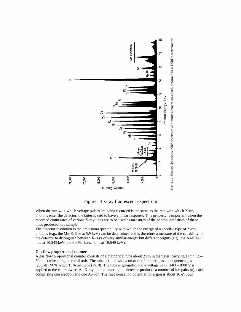
Figure 14 x-ray fluorescence spectrum
When the rate with which voltage pulses are being recorded is the same as the rate with which X-ray photons enter the detector, the latter is said to have a linear response. This property is important when the recorded count rates of various X-ray lines are to be used as measures of the photon intensities of these lines produced in a sample. The detector resolution is the precision/repeatability with which the energy of a specific type of X-ray photons (e.g., the Mn-Ka line at 5.9 keV) can be determined and is therefore a measure of the capability of the detector to distinguish between X-rays of very similar energy but different origins (e.g., the As-Kalpha-1
line at 10.543 keV and the Pb-Lalpha-1 line at 10.549 keV). Gas flow proportional counter A gas flow proportional counter consists of a cylindrical tube about 2 cm in diameter, carrying a thin (25–50 mm) wire along its radial axis. The tube is filled with a mixture of an inert gas and a quench gas—typically 90% argon/10% methane (P-10). The tube is grounded and a voltage of ca. 1400–1800 V is applied to the central wire. An X-ray photon entering the detector produces a number of ion pairs (n), each comprising one electron and one Ar+ ion. The first ionization potential for argon is about 16 eV, but

competing processes during the conversion of photon energy to ionization cause the average energy required to produce an ion pair to be greater than this amount. The fraction relating the average energy to produce one ion pair, to the first ionization potential, is called the Fano factor F. For argon, F is between 0.5 and 0.3 and the average energy ε required to produce one primary ion pair is equal to 26.4 eV. The
number of ion pairs produced by a photon of energy E will equal: ENε
=
Figure 15 Gas filled proportional counter Following ionization, the charges separate with the electrons moving towards the (anode) wire and the argon ions to the grounded cylinder. As the electrons approach the high field region close to the anode wire they are accelerated sufficiently to produce further ionization of argon atoms. Thus a much larger number N of electrons will actually reach the anode wire. This effect is called gas gain, or gas multiplication, and its magnitude is given by M=N/n which typically has a value of around 100,000. Provided that the gas gain is constant the size of the voltage pulse V produced is directly proportional to the energy E of the incident X-ray photon.
Scintillation counter Another type of detector is the the scintillation counter which consists of two parts, the phosphor (scintillator) and the photomultiplier. The phosphor is typically a large single crystal of sodium iodide that has been doped with thallium, denoted as a NaI(Tl) crystal. When X-ray photons fall onto the phosphor, blue light photons are produced (with a wavelength of 410 nm), where the number of blue light photons is related to the energy of the incident X-ray photon. These visual light photons produce electrons by interaction with the surface of the photocathode in the photomultiplier, and the number of electrons is linearly increased by a series of secondary surfaces, called dynodes, inside the photomultiplier. The current

produced by the photomultiplier is then converted to a voltage pulse, as in the case of the gas flow proportional counter. Since the number of electrons is proportional to the energy of the incident X-ray photon, the scintillation counter also has a proportional response.
Solid state detectors The detectors used in the various forms of EDXRF are semiconductor detectors. Conventionally, lithium drifted silicon ( Si(Li) ) The detector crystal itself typically is a disk of very pure Si with dimensions of 4–10 mm diameter and 3–5 mm thickness. In the crystal, the energy difference Eg (band gap) between the valence and conduction band is 3.8 eV. At room temperature, the conduction band is partially populated so that the crystal is a (semi)conductor. To keep the leakage current as low as possible, the crystal is cooled with liquid N2. At a temperature of -196 C almost all electrons remain in the valence band. The radiation to be measured needs to enter the cryostat through a thin entrance window, usually made of Be. By applying a reverse voltage to the charge carrier free intrinsic zone, an absorbed X-ray photon is converted into charge by ionization. Electrons are promoted from the valence to the conduction band, leaving “positive holes” in the valence band; thus the crystal temporarily becomes conducting because n = E/ Eg of electron–hole pairs are created. The electrons and holes are quickly swept to the contact layers by the electric field created by the applied reverse bias on the crystal.

Figure 16 Scheme of the working principle of a Si(Li) detector. Finally it is also possible to disperse the x-rays using a grating (a crystal) in order to send photons of different wavelengths to different angles, where a linear detector is used to count the number of photons. This technique is called energy dispersive XRF. This is shown in figure 17. The monochromator works on
the same principle as x-ray diffraction by a crystal; Bragg’s law: 2 sin hcdE
θ λ= =
Figure 17

Configuration used in x-ray fluorescence setups. Normally the instrument contains a rotating sample holder so that a number of specimens can be analyzed automatically. (Figure 18) The entire system is enclosed in a metal case to prevent radiation hazard. In the “secondary target” EDXRF system shown in Fig.18b. In such a configuration, a high-power (1 kW) X-ray tube irradiates a metal disk (the secondary target, e.g., made of Mo), causing it to emit its own characteristic radiation lines (Mo-Kalpha and Mo-Kbeta). This “bichromatic” fluorescent radiation is then used to excite the sample to be examined. The advantage of the secondary target scheme is that, as a result of the bichromatic excitation, the background in the resulting EDXRF spectra is significantly lower as in the direct excitation case. This leads to better detection limits. By using a filter that preferentially absorbs the Kbeta component of the secondary target radiation (e.g., a Zr foil in case of a Mo target; see figure 12, and table 1), a quasi-monochromatic form of sample excitation can be realized. By interchanging the target (and matching filter), different element ranges can be excited optimally. For example, to obtain the best conditions for determination of trace concentrations of the elements Rb–Nb in geological samples, an Rh secondary target may be selected while for optimal detection of Cr in the same material, a Cu target would be more beneficial.
Figure 18. Schematic drawings of (a) a direct-excitation XRF instrument, (b) a
secondary target XRF instrument.
