x-ray couette shear cell for nonequilibrium structural...
TRANSCRIPT
X-ray Couette shear cell for nonequilibrium structural studies of complex fluids under flow
R. J. Plano Exxon Research & Engineering Company, Annandale, New Jersey 08801
C. R. Safinya Materials and Physics Departments, and the Materials Research Laboratory, University of California, Santa Barbara, California 93106
E. B. Sirota Exxon Research & Engineering Company, Annandale, New Jersey 08801
L. J. Wenzel American Design Corporation, I Bay Street, Stirling, New Jersey 07980
(Received 22 May 1992; accepted for publication 8 December 1992)
We have designed and constructed a sealed, temperature-controlled Couette-type shear cell which allows us to carry out in situ synchrotron x-ray scattering studies of the nonequilibrium structures of complex fluids under flow, probing lengths ranging from the nanometer to the semimacroscopic micron scale. The sealed design allows the cell to be tilted, facilitating the scanning of all directions in reciprocal space. In contrast to existing neutron shear cells, we access the shear plane containing the velocity and the velocity gradient. The temperature control of the cell enables us to carry out phase transition studies far from equilibrium. The complex fluid systems which may be studied with this cell include thermotropic and lyotropic liquid crystals, microemulsions, and polymeric fluids. Recent results on the nematic and smecticd phases of a liquid crystal, and the disordered bicontinuous L3 phases of surfactant membranes in the vicinity of the ordered lamellar L, phase under flow, are presented.
I. INTRODUCTION
We describe an apparatus that enables us to use high- resolution synchrotron x-ray scattering techniques to study the nonequilibrium dissipative structures of complex fluids under shear flow in a sealed and temperature-controlled cell. The specific complex fluid systems suitable for study with this shear cell consist of thermotropic liquid crystals, lyotropic surfactant membranes in solution such as the lamellar and bicontinuous microemulsions, and polymers in solution.’ For complex fluids with viscosities in the 10 CP range (e.g., nematic and smecticd liquid crystals), shear rates of lo5 sag ’ may be reached under controlled temperature conditions between room temperature and 60 “C!. Samples which have viscosities in the 103-lo4 P range may be run at shear rates of order lo3 s-’ under controlled temperature conditions.
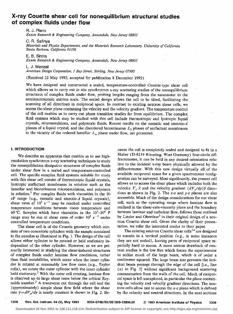
The shear cell is of the Couette geometry which con- sists of two concentric cylinders with the sample contained in the annulus as illustrated in Fig. 1. The design of the cell allows either cylinder to be rotated or held stationary in- dependent of the other cylinder. However, as we are pri- marily interested in studying the shear-induced structures of complex fluids under laminar flow conditions, rather than fluid instabilities, which occur when the inner cylin- der is rotated at reasonably low flow rates (e.g., Taylor rolls), we rotate the outer cylinder with the inner cylinder held stationary.2 With the outer cell rotating, laminar flow is observed up to large shear rates below the critical Rey- nolds number.’ A transverse cut through the cell and the (approximately) simple shear flow field where the shear rate j=dV.Jdy is nearly constant is shown in Fig. 2. Be-
cause the cell is completely sealed and designed to fit in a Huber (D-82 19 Rimsting, West Germany) four-circle dif- fractometer, it can be held in any desired orientation rela- tive to the incident x-ray beam physically allowed by the diffractometer. With this new design virtually all of the available reciprocal space for a given spectrometer config- uration can be surveyed. Most significantly, the present cell allows us to access the shear plane which includes both the velocity V, 2 and the velocity gradient (dV,/dy)P direc- tions as shown in Fig. 2. The x-z and y-z planes are also accessible. Much of the design considerations for our shear cell, such as the operating range where laminar flow is realized in the shear-rate-viscosity plane and the boundary between laminar and turbulent flow, follows those outlined by Linder and Oberthur3 in their original design of a neu- tron Couette shear cell. Given the clarity of their presen- tation, we refer the interested reader to their paper.
The existing neutron Couette shear cells3’4 are designed to remain in a vertical position (e.g., in some instances they are not sealed), leaving parts of reciprocal space es- pecially hard to access. A more serious drawback of neu- tron studies is the low flux which forces the experimenter to utilize much of the large beam, which is of order a centimeter squared. The large beam size prevents the inci- dent beam passage through the edge of the cell [i.e., line (a) in Fig. 21 without significant background scattering contamination from the walls of the cell. Much of recipro- cal space is left unexplored, in particular the plane contain- ing the velocity and velocity gradient directions. The neu- tron cells allow one to access the x-z plane which is defined by the velocity and neutral directions. In the next sections
1309 Rev. Sci. Instrum. 64 (5), May 1993 0034~6748/93/051309-l o.fio6.00 0 1993 American institute of Physics 1309
Downloaded 26 Nov 2001 to 128.111.119.114. Redistribution subject to AIP license or copyright, see http://ojps.aip.org/rsio/rsicr.jsp
Outer cylinder
Inner cylinder
I II ii i I II
2 ! Annulus containing sample
Cylinder holding assembly
Side View
..- Sample /
Tap cross-sectional view
FIG. 1. Couette geometry as used in shear cell.
we give a detailed description of the shear cell apparatus followed by some experimental results of a nematic liquid crystal under shear flow in the vicinity of the nematic to smectic-rl phase transition and a brief description of results from a study of the lyotropic lamellar L, and bicontinuous L3 phases with internal structures comprised of surfactant membranes.
II. DESIGN CONSIDERATIONS Among our prime requirements was that the entire cell
fit in the x circle of a Huber diffractometer (model 511).
Incident
“/- Texan cylinders
y (W 1
mes
Outer wall -v-v.
/ctzzz”: PJ)
FIG. 2. Transverse cross section through Lexan cylinders showing three scattering geometries: (a) 1$=90, (b) +=45, and (c) +=O and represen- tation of velocity gradient across gap. Also shown is the coordinate sys- tem as described in the text.
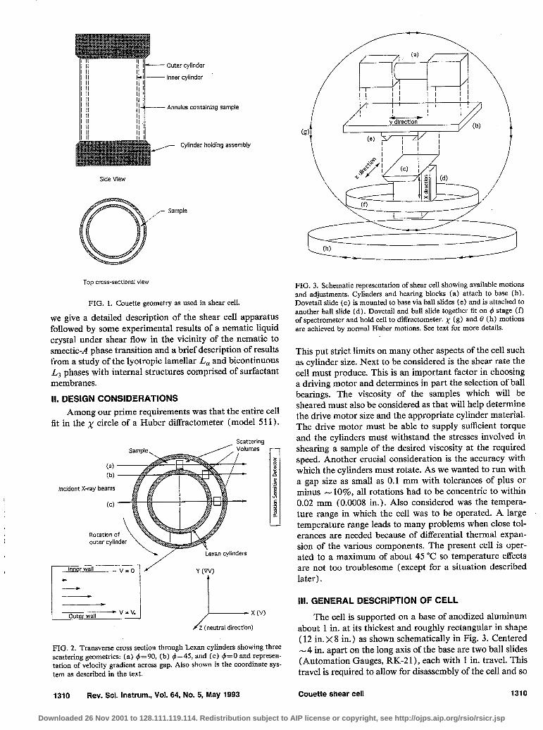
FIG. 3. Schematic representation of shear cell showing available motions and adjustments. Cylinders and bearing blocks (a) attach to base (b). Dovetail slide (c) is mounted to base via ball slides (e) and is attached to another ball slide (d). Dovetail and ball slide together fit on #J stage (f) of spectrometer and hold cell to diffractometer. x (g) and 0 (h) motions are achieved by normal Huber motions. See text for more details.
This put strict limits on many other aspects of the cell such as cylinder size. Next to be considered is the shear rate the cell must produce. This is an important factor in choosing a driving motor and determines in part the selection of ball bearings. The viscosity of the samples which will be sheared must also be considered as that will help determine the drive motor size and the appropriate cylinder material. The drive motor must be able to supply sufficient torque and the cylinders must withstand the stresses involved in shearing a sample of the desired viscosity at the required speed. Another crucial consideration is the accuracy with which the cylinders must rotate. As we wanted to run with a gap size as small as 0.1 mm with tolerances of plus or minus - 1096, all rotations had to be concentric to within 0.02 mm (0.0008 in.). Also considered was the tempera- ture range in which the cell was to be operated A large temperature range leads to many problems when close tol- erances are needed because of differential thermal expan- sion of the various components. The present cell is oper- ated to a maximum of about 45 “C so temperature effects are not too troublesome (except for a situation described later).
HI. GENERAL DESCRIPTION OF CELL
The cell is supported on a base of anodized aluminum about 1 in. at its thickest and roughly rectangular in shape (12 in. x 8 in.) as shown schematically in Fig. 3. Centered -4 in. apart on the long axis of the base are two ball slides (Automation Gauges, RK-2 1 ), each with 1 in. travel. This travel is required to allow for disassembly of the cell and so
1310 Rev. Sci. Instrum., Vol. 64, No. 5, ‘May 1993 Couette shear cell 1310
Downloaded 26 Nov 2001 to 128.111.119.114. Redistribution subject to AIP license or copyright, see http://ojps.aip.org/rsio/rsicr.jsp

that various length cylinders may be employed for diEerent experiments. Mounted on top of each slide is a machined stainless-steel block, roughly 1.5 in. x 1.5 in. ~2.5 in. with a 1.25 in. hole bored along the long axis. These blocks hold the bearings and rotating parts of the cell. The sides of the blocks have been lapped to ensure that the blocks are the same size, the cross section is accurately square, and the central hole is centered and perpendicular to the end faces. By using the free play around the screws and shims under- neath, the blocks can be made coplanar and parallel with each other to within 0.002 in.
The #-stage mounting plate of the Huber model 410 diffractometer is replaced by an assembly that enables the shear cell to be adjusted in two directions relative to the Huber. This assembly [Figs. 3 (c) and 3(d)] consists of a dovetail slide mounted perpendicularly to the end of a ball slide. The dovetail mates with a dovetail groove on the bottom of the shear cell base and is threaded to accept a lead screw which is also mounted on the base. This lead screw is motorized to enable adjustments in the z direction (parallel to x-ray beam) to be made. The carriage of the ball slide is screwed to the dovetail (and thus attaches to the shear cell) while the base is attached to the 4 stage. Another motorized lead screw is used in the ball slide to move the cell in a direction perpendicular to the x-ray beam. This is represented as the x direction in Fig. 3. The x and z motions are used to center various parts of the cell on the beam and, when used together, mimic the effect of rotation of the 4 circle which allows us to access either the V or the VV directions. The motion in the x direction is also used alone to scan the cell through the beam and thus accurately define the center of the gap by measuring the attenuation of the x rays by the Lexan cell wall. A third orthogonal adjustment (v direction) is made possible by ball slides mounted between the dovetail groove and the shear cell base and is controlled by a third lead screw. It is very important that the cell have these three motions in- dependent of the Huber. These degrees of freedom allow us to put different volumes of the sample at the center of rotation of the Huber so that the same volume is sampled during an angular scan.
Reference to Fig. 4 would be useful during the follow- ing description of the cell construction. The rotating parts of the cell consist of an inner spindle supported by two ball bearings (Barden, No. SRlDlZSSTA), one near each end, and an outer spindle, also supported by two ball bearings (Barden, No. SR1828SSSTA) all concentric with the hole in the stainless-steel block (the two blocks and the com- ponents they hold are identical mirror images). Sprockets (PIC, Nos. FMGl-016 and FMG5-025) are mounted on one end of the spindles while the other end is machined to receive either the inner or outer cylinder arbor, as appro- priate. The inner cylinder arbor is held in a recess in the spindle by the injector rod, which is basically a hollow tube threaded at one end to fit into the arbor. The outer arbor is held around its outer diameter by the outer spindle and kept in place by a lock nut. A magnetic seal (Magnetic Seal Corp, No. 62-5 style A), located immediately behind the
1311 Rev. Sci. Instrum., Vol. 64, No. 5, May 1993
FIG. 4. Sample is introduced from syringe to injector rod (2) via special end cap (1 j, which also allows for the thermistor wires to pass through to various connections. Pressure from syringe forces sample through injector rod to inner cylinder arbor (14) and out through radially drilled holes to annulus created by inner and outer cylinders ( 11,12). Inner spindle (3) is supported inside outer spindle (6) by two ball bearings (4) and rotated by belts driving a sprocket (20). Outer spindle is held by two ball bearings (5) concentric to cylindrical hole in bearing housing (7) and rotated by a sprocket ( 19). Bearings are ‘preloaded by spring washers (8 j to allow for thermal expansion during operation. The bearing housing is mounted on a spacer block (22) and a linear slide (23) to the base plate. Inner and outer rotating parts are separated by magnetic seal (15, 16). Carbon ring part of seal (15) is held by O-ring on inner cylinder arbor, magnetic part (16) is positioned by outer spindle. Outer cylinder holder (10) is secured by locking ring (9) which screws onto outer cylinder spindle. Tempera- ture control is facilitated by the five thermistors located inside the inner cylinder and held by delrin (acetal) holders (13) which are screwed to inner cylihder arbor. The hole that goes straight through the inner cylin- der arbor is sealed with Torr Seal epoxy at the point where the thermistor Wires enter. Two thermistors are located at each end of the cylinders and one is at the center. The tube through which the temperature controlled air flows from the vortex guns is held in position by a delrin block (21). The delrin block is clamped to the bearing housing by set screws. If a small amount of the sample material should get past the magnetic seals, a felt pad (17) is positioned to absorb it. In case of a catastrophic seal failure, there are four holes (18) drilled in the outer spindle to sling any material out before the bearings can be contaminated. This, of course, works only if the outer cylinder is rotating. (Some fasteners have been omitted from figure for clarity.)
inner arbor, is used to seal the cylinders from the surround- ing atmosphere.
Filling the cell is accomplished by introducing the sample through the injector rod via the special end cap described below. The inner arbor is hollow, with passages leading radially to its outer diameter. The sample flows through these passages to the annulus created by the Lexan cylinders, through the passages in the other inner arbor and out the other injector rod.
The nucleus of the cell is the two Lexan cylinders that contain the sample and produce the shear stress. Lexan was chosen as the material for the cylinders for a variety of reasons. First, because Lexan is made of low Z (low elec- tron density) polymeric materials, it is highly transparent to x rays, having a l/e absorption of about 2 mm for 8 keV photons (corresponding to the Cu K, line). Most of the experiments were done near this energy, both in-house on our rotating anode x-ray generator and at synchrotron fa-
Couette shear cell 1311
Downloaded 26 Nov 2001 to 128.111.119.114. Redistribution subject to AIP license or copyright, see http://ojps.aip.org/rsio/rsicr.jsp

cilities. Second, Lexan is optically. transparent enough to allow one to see the sample and check for trapped air bubbles and ensure that the flow is laminar. Third, the material is strong enough to withstand the shear stresses produced but flexible enough to ease assembly.
The cylinders are machined from cylindrical Lexan stock to a wall thickness of 0.5 mm and measured to be round to within 0.0254 mm total included runout (TIR) on the critical surfaces (outer surface of the inner cylinder and the inner surface of the outer cylinder). Gap sizes of 0.1, 0.25, and 1.0 mm have been produced and run suc- cessfully on the instrument. The typical outer diameter for inner cylinders is 20 mm while the outer cylinder is 23 mm. Length for both cylinders is 48.5 mm in the most fre- quently used size.
The two cylinders are held at each end, concentric to each other, by the inner and outer rotating arbors. As stated above the cylinder arbor spindles are rotated by belt- driven sprockets. These sprockets are driven by a Min-E- PitchTM belt (3CCF Series, from W. M. Berg) from one of two drive shafts that are mounted parallel to and on either side of the Lexan cylinder assemblies.
A. Temperature control
A major source of difficulty in achieving and maintam- ing a desired temperature was dealing with the large amounts of heat produced by the magnetic seals. These seals basically consist of a ring of carbon held against a polished steel face by magnetic attraction. They are located adjacent to the inner cylinder arbor and thus have a sig- nificant effect on the temperature of the sample. Even at the lower rotation rates a large amount of heat is produced by the friction between the two parts of the seal. This heat must be dissipated away if accurate control at temperatures approaching ambient is to be realized.
In order to accomplish precise temperature control, thermistors (YSI No. 44011) are located inside the inner cylinder (which must then be clamped stationary). A hole drilled completely through the long axis of the inner cyl- inder arbor allows the thermistor wires to pass from the injector rod to inside the inner cylinder. A small Delrin holder attaches to the arbor and holds up to three ther- mistors. The thermistors are epoxied to the Delrin holder using thermally conductive epoxy (Tra-Con, No. 2 15 1) in such a way that they make good thermal contact with the wall of the cylinder. A thin layer of thermal grease (Wake- field Eng’g, Thermal compound No. 120-2) between the epoxy and the cylinder wall tills any gaps and ensures this contact. This arrangement of thermistors allows us to mea- sure the temperature of the sample very close to where the x-ray beam impinges on it.
Devices known as vortex guns (Exair Corp., Cincin- nati, OH) are used to blow temperature-controlled air on the ends’of the cell near the magnetic seal area. A vortex gun consists of a pipe, open at both ends, with an inlet for high-pressure air perpendicular to the long axis of the pipe near one end. The inlet is connected to a compressed air source (80-100 psi) which results in hot air blowing out one end and cold air out the other. From the cold end of
the gun the air travels through a short length of Tygon tubing, the end of which is fitted over a piece of 0.5-in.- diam copper tubing. This tubing in turn is connected to a machined Teflon block that sits on the bearing housings. The Teflon blocks direct the air to the area of the cell where the seals are contained. To control the temperature of the air coming out of the cold end of the vortex guns, a cartridge heater is located inside the copper tubing. The voltage sent to the cartridge, and thus the amount of heat it puts out, is determined by the reading of the thermistors inside the inner cell.
The thermistor wires (30 AWG magnet wire) pass through the hole in the arbor, which is sealed with Torr- Seal (Varian), and travel up the injector rod. The other end of the injector rod is open to the outside and easily accessible. A cap fits over the end of the injector rod and is held there and sealed by O-rings (all O-rings used in the shear’ cell are made of Viton for solvent resistance and purchased from Apple Rubber Products, Lancaster, N.Y.). The cap has two holes in it opposite from the hole where the injector rod fits. One hole is threaded to accept miniature tubing fittings and is where the syringe contain- ing the sample is attached. The other is used for the ther- mistor wires to pass through and is sealed by a rubber plug. To pass the thermistor wires through this plug a syringe needle is pushed through it, the wires fed through the nee- dle (this is one reason such thin wire is used) and the needle withdrawn, creating a tight seal between the plug and the wire. To simplify connections to the thermistor wires a terminal strip is epoxied to the shear cell base. Multiconductor cables are used to connect the terminal strips to the various temperature controllers and other in- struments.
To accurately measure and control the temperature of the sample a total of five thermistors inside the inner cyl- inder are required. One thermistor is located in the center of the cylinders, against the wall of the inner cylinder, out of the way of the incident x-ray beam (see Fig. 4). The other four thermistors are located at the ends of the cylin- der, two to an end. The middle thermistor and one end thermistor are monitored continuously. One thermistor from each end is connected to a precision temperature con- troller which sends signals to power supplies which in turn send power to the cartridge heaters in the vortex gun air flow. The cylinders are enclosed by a two-stage, cylindri- cally symmetric oven. The outer oven housing is mainly to reduce the effect of stray air currents. To reduce the effects of radiation (in the thermal range), a sheet of aluminized mylar is used to cover the Lexan windows of the oven. With this arrangement of heaters and sensors, the temper- ature of the sample is maintained within 0.01 “C over more than 10 h and within 0.005” over l-2 h.
B. Speed control
In our experiments to date, a single dc motor has been used to drive the outer cylinder and to clamp the inner cylinder stationary. The main reason a dc motor was cho- sen over a stepping motor was that the torque produced actually increases with rpm. At the upper rpm limit, the
1312 Rev. Sci. Instrum., Vol. 64, No. 5, May 1993 Couette shear cell 1312
Downloaded 26 Nov 2001 to 128.111.119.114. Redistribution subject to AIP license or copyright, see http://ojps.aip.org/rsio/rsicr.jsp
torque produced by stepping motors is essentially zero. (a) The dc motor (Motomatic E-652) has a tachometer built
DECREASING TEMPEWTURE -
into it forming a feedback loop which results in highly ,,‘L ‘i, I’+ 4 i
lllllll1lII
accurate ( ~0.5%) speed control. The controller was eas- ’ \/ IIrIIIIliII~
ily interfaced with the computer allowing for computer \ -‘\ I i”+l\
\’ ’ I I I
l1111111111 d 111111111117-
control and monitoring of the shear rate. ISOTROPIC NEMATIC SMECTIC - A
C. Shear cell in use
Preparing the shear cell assembly for actual use on the spectrometer involves a thorough cleaning of all the indi- vidual parts before assembly may begin.
To verify that the cell will rotate within tolerances during the experiment, measurements are taken at certain times during assembly. After both inner cylinder arbors are in place a dial indicator is’ used to measure the rotational runout of the arbors. If the runout is greater than 0.001 in. TIR, the injector rod is loosened from the inner arbor and the arbor is rotated relative to the inner spindle as different relative orientations can lead to slightly different runouts, and the injector rod is tightened into place again. This procedure is repeated until the required tolerances are ob- tained. Measurements are also taken of the outer cylinder arbors after they are installed.
Filling of the sample is normally done with the cell in a vertical position (i.e., long axis of Lexan cylinders verti- cal) as this minimizes the volume where air bubbles may be trapped, In the case of low viscosity fluids, tilling is a simple matter of attaching a syringe full of the sample (typically about 15 cc) to the end cap, turning the outer cylinder at a low rate (10-15 rpm) to discourage bubble formation, and slowly introducing the sample via the in- jector rod. For a higher viscosity sample such as the liquid crystal 8CB (BDH Industries) which changes phase with temperature, we have devised a technique to simplify load- ing. Before being pulled into the loading syringe, the 8CB is heated above the isotropic transition temperature ( 40 “C) where it becomes much less viscous and trapped air is released. The entire shear cell is also heated using the oven and a hand-held heat gun for the areas not covered by the oven such as the bearing housings and the end caps. When the entire assembly is warm the 8CB is introduced and flows in quite easily.
We now turn to a brief discussion of our recent exper- imental results, which are described more completely else- where.‘? ”
IV. EXPERIMENTAL RESULTS ON THE NEMATIC TO SMECTIC-A PHASE TRANSITION UNDER FLOW
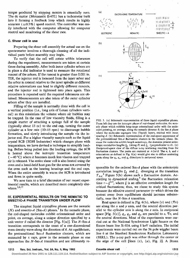
The simplest liquid crystalline phases are the nematic (N) and smecticd (Sm-A ) phases.’ In the nematic phase, the rod-shaped molecules exhibit orientational order and point, on average, along a unique direction specified by a unit vector n^ called the director [Fig. 5(a)]. The N-Sm-A transition corresponds to the onset of a one-dimensional mass density wave along the direction of n^. At equilibrium, the pretransitional Sm-A fluctuation clusters, which are measured by x rays, grow in the nematic phase as one approaches the N-Sm-A transition and are ultimately re-
(b)
(cl
FIG. 5. (a) Schematic representation of three liquid crystalline phases. From left they are the isotropic phase of rod-shaped molecules; the nem- atic phase which exhibits long-range orientational order with the mole- cules pointing, on average, along the nematic director A; the Sm-A phase where the molecules segregate into (liquid) layers, stacked with mean spacing d. (b) Schematic representation of the real-space appearance of the pretransitional Sm-A fluctuation clusters in the nematic phase. Be- cause the molecules exhibit length anisotropy, the domains present aniso- tropic correlation lengths 5,, (along fi) and jr (perpendicular to fi). (c) Reciprocal-space view of the diffuse x-ray scattering resulting from the fluctuation clusters. The peaks are centered at &an-/d. The a, b, and c orientations as defmed in Fig. 8(a) would give rise to diffuse scattering spots along the qn qn and qv directions in reciprocal space.
sponsible for the ordered Sm-A phase with the anisotropic correlation lengths ~II and g1 diverging at the transition TNA.8 Figure 5(b) shows such a fluctuation domain. AG
cording to dynamical scaling,’ the fluctuation relaxation time r- {si2, where 6 is an effective correlation length for critical fluctuations; thus, we chose to study this system because the effective control parameter pi which drives the system away from equilibrium should increase substan- tially, near the N-Sm-A transition.
Real space is defined in Fig. 6 (b) , where (v) and (Vu) are along the x and y axes, and the neutral direction par- allel to the cylinder axis is along the z axis. In reciprocal space [Fig. 5(c)], qx, .q,, and qn are parallel to U, Vu, and the neutral directions. Most of the experiments were car- ried out at the National Synchrotron Light Source on the Exxon beam line X-1OA using 8 keV radiation. The initial experiments were carried out on the 56 pole wiggler beam line 6 at the Stanford Synchrotron Radiation Laboratory (SSRL). The x-ray path was either through the center or the edge of the cell pines (c), (a), Fig. 21. A Braun
1313 Rev. Sci. Instrum., Vol. 64, No. 5, May 1993 Couette shear cell 1313
Downloaded 26 Nov 2001 to 128.111.119.114. Redistribution subject to AIP license or copyright, see http://ojps.aip.org/rsio/rsicr.jsp

W “2 “b” “6 c .*+;* ;.‘;:A*.. ‘* .
--_ - ~.~~=.:.....**.**=O~.
r.:e.“:‘.: e.‘. ----”
.*. l : - =zz - =-
- .- l ::: . l a : a : .
=,-=
y, f#p 1, I[
:**a l -*:**: a’ : - .*.*. =.. .* .a,.. a *Me.* -EL . ---= -
l +-llu!L l’,ll’i(, ’ ’ /I)
(b)
n-t 4 -v
FIG. 6. (a) Three simple orientations for ii under shear flow. In the rightmost picture, a Sm-A fluctuation in the c orientation is shown. (b) A Smd fluctuation that has the 6 orientation is shown at rest (left) and under shear (right) which tilts the layers.
PSMJO linear detector placed 95 cm after the sample was positioned as shown in Fig. 2, so that the scattering com- ponent collected in the channels was along qx(q,,) parallel to v( Vu) when going through the center (edge). The setup gave a qz resolution of 3 X 1O-4 A-’ (HWHM), with a linear-detector resolution of 1.2 x 10m3 ,k (HWHM).
The three simple orientations that n^ may assume under flow and their associated viscosities are shown in Fig. 6(a). The a, b, and c orientations refer to n^ pointing along the neutral 2, the velocity R, and the velocity gradient jJ direc- tions, respectively. For a uniform sample with the c orien- tation where n^=j, the diffuse x-ray scattering arising from the pretransitional Sm-il fluctuations is centered in recip- rocal space at q=q& = (2?r/d) fi along the qy axis, where the width of the diffuse spot is proportional to l/cl, and l/& measured parallel and perpendicular to fi, respec- tively. Figure 5(c) shows this diffuse spot along with those produced when ri is along the i, 2, and a general orienta- tion between 9 and 2. For this general orientation n^ (ar- row), the spot is also along n^.
We show in Fig. 7 the P-T phase diagram with em- phasis on the distinct narrow regimes in the immediate
I ac 1% lam
mA-
TEMPERATURE pq
FIG. 7. (Bottom) The P-T phase diagram for 8CB as discussed in the text. (Top) Schematics of the stable orientation of ii in the b regime (right), and the distribution of &in three of the a regimes.
vicinity of TNA. The solid squares indicate thermodynamic transitions from the isotropic to the N phase (TIN ~41 “C), and from the N to the Sm-A phase (T,=33.58 at p=lO s-r), which shows an unexpected reentrant be- havior. In the Sm-A phase, A assumes the a orientation but at lower temperature crosses into a regime where Sm-A domains with both the a and c orientations coexist. Over a 2” range below TIN, we find that $ lies in the shear plane in the b orientation with the diffuse scattering centered at qzq& This stable orientation for rz^ is shown schemati- cally at the top right of Fig. 7. As we further lower T, A undergoes a flip transition, through an intermediate regime labeled a-b in Fig. 7, to a region near T, where the av- erage orientation of n^ is along 2. However, this nominally a regime consists of four crossover regimes a,, a, a(b), a,. The shaded areas covering the unit spheres at the top of Fig. 7 are schematics of the distribution of n^ for three of these regimes.
To understand the evolution in the anisotropic ellipti- cal distribution of n^ about z^ as the ordered Sm-A phase is approached, we consider the orientational state of n^ under flow which is determined by the total forces acting on it. The equation of motion (EOM) for n^ is given by’“-‘2
r-u+ rf=O, (1)
where If= -fix h, is the torque on fi, due to the fluctu- ation domain, where for jr < 1 with v=p,$,
hf= -(r/2) &,T/&,, ) (?7-) (n^ * 0)y+0(~~)*. (2)
The viscous torque on n^ is given by the Ericksen- Leslie-Parodi (ELP) theory of the hydrodynamics of nem- atics which considers the viscous and elastic torques on 2.” According to ELP nematodynamics, in the high-shear regime where elastic torques are negligible, the viscous torque on fi is”
1) r”= --AX y1 ~+~b,ny,a,n,,O) ,
1 1 where the .Ericksen viscosity parameters aZ = (“/z - y, )/2, and a3 = ( y2 + y1 )/2, are defined in terms of the rotational viscosity y1 and shear viscosity yp It follows from Eq. ( 1 ), that the viscous torque, IYU= @2i and ( ja3z”) for n^ =9 and (n”=x^); thus cx2 and a3 are proportional to qc and v6, respectively [Fig. 6(a)].
The physical origin of the fluctuation induced torque, If, is due to the effect of shear flow on the Auctuation domains. Figure 6(b) shows that for a temporal fluctua- tion domain with ri=f pointing along v in the b orienta- tion, shear flow tends to tilt the layers, which changes the layer spacing and gives rise to the restoring force h, In contrast, shear flow does not alter the internal structure of fluctuations with the a and c orientations. We see from Eqs. (l)-( 3) that to lowest order in jr, the effect of fluc- tuations is a renormalization of a: ( cc vb) :
~=ar3+(~/2)(ksT/d2)(~/5,, 1. (4)
For all nematics studied to date, a2 < 0, and the flow orientation of fi depends on the sign of a3. Normally, far from T, where fluctuations are negligible, a3 <O with
1314 Rev. Sci. Instrum., Vol. 64, No. 5, May 1993 Couette shear cell 1314
Downloaded 26 Nov 2001 to 128.111.119.114. Redistribution subject to AIP license or copyright, see http://ojps.aip.org/rsio/rsicr.jsp

CY~/CY~(~. The stable solution of the equation of motion (EOM) I’,=O, then results in n^ lying in the (u- Vu) shear plane at a small angle 8= tan- ’ (a3/~~2) “*=5’ with the flow direction as we show at the top right of Fig. 7. This is essentially the b orientation of Fig. 6(b). As temperature is reduced towards TNA, the growth of pretransitional Sm-A fluctuations drives alp through zero towards large positive values as T-f T, and yr approaches 1. When a; > 0, there is no stable solution in the shear plane. However, there is a zero torque sohrtion if n^ points exactly along the neutral 2 direction; this is the a orientation of Fig. 6(a). In this limit with a; () [ a3 \ ) > 0, Eq. ( 1) reduces to lowest order in n, nP and i/7 tot0-12
(5b)
where we consider deviations of n^= ( nx,n,,, 1) away from the z axis, and w$== p ( - a2af )/d. Equation ( 5 ) describes a coupled-harmonic-oscillator motion for iz, and n,, with precession frequency oa. The coupling of the precession modes, which are of the form n,(t) =nxo cos(w,t) and n,(t) =nlo sin(oct>, describe an equation of an ellipse:
n,(t)~/2/n~+n,(t)2/n~=l. (6)
Thus, the EOM describes an anisotropic precession of n^ on a unit sphere about th’e z axis, where the projection of 2 onto the x-y plane will be elliptical with a well defined ratio of axes n.Jn@ We expect that the precession of n^( t) about 2 should be accompanied by wanderings, due to ther- mal or hydrodynamic noise, between different amplitude states nd and nfl, but with a ratio of amplitudes n.Jnfl = ( -a2/af) 1’2 fixed by temperature. Therefore, the dis- tribution of fi about 2 would also be anisotropic with an elliptical projection on the x-y plane with eccentricity nJ nlo, which we expect to be strongly temperature-dependent due to the critical behavior of a? near TN,. This is pre- cisely what we find near T,, as we show in Fig. 8.
qllw s,wJ) qxW)W)
FIG. 8. (b)-(e) Equal-intensity contours of the x-ray intensity in the q,-qy qz-qr and qz-qx planes through CO,O,q,=q,,) in the four a regimes at ’ j=300 s-‘. The intensity levels normalized to the peak (central dots) fall off as 1 :i:$:f:a:f:k:&:&:&. The data are for decreasing T-TNA: (b) t=0.0035, (c) 0.000 82, (d) 0.00026, and (e) 0.00005. The evolution in the shapes of the contours is due to the divergence of the viscosity of arising from the critical slowing down of the order-parameter fluctuations. (a) Result of fit of the data of (b) with I(q) as discussed in the text.
These four regimes exhibit distinct x-ray scattering profiles. For an arbitrary orientation of n^, the diffuse spot
In the a, regime the elliptical distribution in the (qx-q,,)
is at q-q& in reciprocal space as we show in Fig. 5(c); shear plane has its major axis along qx ([I v) with nJnuo > 1, which would correspond to the range where
thus, because the peak q-vector points along 2, one is able a$ < --a*; this is consistent with the anisotropic distribu- to measure its orientation. For an anisotropic (or isotro- tion in the other two planes which is more spread out in the pic) distribution of n^ about the z axis, the diffuse scattering (qz-qx) plane indicating larger deviations of n^ towards would now be on a corresponding anisotropic (or isotro- the v direction as compared to the Vu direction. With in- pic) “patch” of a sphere of radius q. centered about the qz creasing a?, the elliptical shapes of Fig. 8 (left column) are axis. To elucidate the orientational distribution of fi, we first squashed into an almost circular shape in the “a,” plot in Figs. 8 (b)-8 (e), equal intensity contours at p= 300 s _ ‘, of cuts in the three planes ( qz-qx) , (4=-q,,), and ( qx-q,,) ,
regime, where n&n@= 1 which indicates that a?= -a*, and then become elliptical again in the “a(b)” regime, but
through the point (O,O,qz=qo), at one reduced temperature t= CT- TNA)/TNA
now with the major axis along qy (11 Vu) with nxo/nlo < 1 in each of the four regimes [a,, a, because aj( > -a2. This is consistent with cuts in the other
a(b), a,]. In our description, we emphasize the overall two planes in Figs. 8(c), 8 (d) (center and right), where shapes of the contours. In particular, the elliptically shaped the distribution of 2 becomes confined to a narrow isotro- intensity distributions in the (qx-qy) shear plane (Fig. 8, pic cone about the qr axis in the a, regime, and slightly left column ) , which result from an anisotropic distribution anisotropic again in the a(b) regime with larger deviations of fi about the z axis are self-evident. We see clearly that in the (4=-q,,) plane. Finally, the elliptical contour of Fig. the shapes evolve as a function of decreasing temperature. 8(e) (left) exhibits extreme anisotropy in the a, regime
1315 Rev. Sci. Instrum., Vol. 64, No. 5, May 1993 Couette shear cell 1315
-.038 0 .038 -.03 0 .OQ 0 .OQ
Downloaded 26 Nov 2001 to 128.111.119.114. Redistribution subject to AIP license or copyright, see http://ojps.aip.org/rsio/rsicr.jsp

where a$ -c+, and the contour lines in the ( qz-q,,) plane extend to the qu axis [Fig. 8(e), center]. The distribution of 6 about .?, now extends down to the Vu direction as we show in the top left of Fig. 7.
To estimate the growth in the ratio af/a,, we chose a sensible functional form for the orientational distribution function averaged over time and the sample volume: (W(E)) =exp[-(ni&,+n;o$]; with ax/cry=nxo/ng = ( - a2/a3> 1’2. The x-ray intensity
I(4) a JJ d&&g we W(q,fiL
where S(q$) is the diffuse scattering due to pretransitional Sm-A fluctuations.i3 We show contour plots in Fig. 8 (a), which are a result of a nonlinear-least-squares fit of the data of Fig. 8 (b) to I(q), which qualitatively reproduce our data. Over the nominal a regimes which span a re- duced temperature range of 4X 10m3 < t < 5 X lo-‘, a$/ 1 a21 = (n.Jtzfl)2 varies by a factor of ~70. In 8CB, 1 a2 1~3 P (see Ref. 14) independent of T; thus, over the
same temperature range, we estimate from Eq. (4) that the fluctuation relaxation time 7s (2/s-)af(Q d2/kBT) grows between x 10-5.
z 1 ps for t=4x 10e3 to ~10~ pus for t=5
V. THE DISORDERED L, SPONGE PHASE UNDER SHEAR FLOW
In another recent experiment we looked at the effect of shear flow on the dilute lamellar L, and and the L3 bicon- tinuous phases of surfactant membranes. Figure 9 shows the phase diagram mapped out at equilibrium.i5 The sys- tem comprises four components: water, sodium dodecyl sulphate, dodecane, and pentanol. The samples studied were in the oil (dodecane) rich part of the phase diagram.
The membrane surfaces that we consider are made of surfactants which are amphiphilic molecules. They contain a hydrophilic (polar) head group and a hydrophobic (oily) hydrocarbon tail (or tails) shown schematically in Fig. 9. While the polar head “likes” water, the tails will be expelled from it (because of the hydrophobic interaction). A multilayer system then consists of stacks of alternating membranes (comprised of a thin water layer coated with surfactant and cosurfactant), and solvent (primarily dode- cane with some pentanol) as we show in Fig. 9. In the lamellar L, phase, the constituent molecules behave as a fluid diffusing freely inside each two-dimensional bilayer. From a structural view point, the L, phase has the same symmetry as the Smd phase of thermotropic liquid crys- tals. As one dilutes the L, phase with oil separating the layers, the L, melts into the random bicontinuous L, phase, where one loses both the one-dimensional density wave normal to the layers and the long-range orientational order of the lamellar phase (which is optically uniaxial). In the L3 phase, but close to the L, phase boundary, one expects to see fluctuating L, domains as we show schemat- ically at the bottom of Fig. 9.
As we discussed earlier, in the nemafic to Sm-A study, near the N-Sm-A transition, the nematic director points along the cylinder z axis (i.e., a geometry) so that the
1316 Rev. Sci. Instrum., Vol. 64, No. 5, May 1993
Pentanol
e
&id y - ji\ 0 oil
oil
I.3 \
Lgwith fluctuating L, domains
FIG. 9. Quaternary phase diagram of L, and L, samples. This diagram is taken at a cut where the water/SDS ratio is held constant at 1.552 and the oil and pentanol content is varied. The L, phase consists of stacked lipid bilayers with oil between the bilayers and water within the bilayers, separated by an average distance d. The inset diagram shows a schematic view of one of these layers. The larger tailed spheres represent the SDS molecules while the smaller ones represent dodecane molecules. The L, phase is analogous to a sponge, with two volumes of oil separated by a convoluted lipid bilayer. In the high dodecane region of the L, phase, temporal fluctuations of L, domains are present. In the diagrams the director is represented by the small arrows.
scattering is centered at (O,O,q,=2r/d=O. 198 ii-‘) in re- ciprocal space away from the origin as shown in Fig. 5 (c). Because dz3 1.73 A is of order the molecular dimensions, the scattering occurs at a reasonably large q vector away from the origin. In this case the v-Vu (qn-q,,) shear plane was readily accessed with the incident beam going through the center of the cell [line (c) of Fig. 21, through a single q,, scan along the Vu direction with the linear detector chan- nels collecting data along the velocity direction (i.e., along the qx direction). Thus, a single scan (which primarily involves tilting of the shear cell), yielded the scattering data projected in the shear plane and centered about (O,O,qJ away from the origin.
In the dilute L, and L, phases, where we are carrying out our studies, the interlayer spacing is large. For exam- ple, the L3 region that we discuss (shown schematically in Fig. 9) has an average interlayer spacing of order 800 A. Hence, the scattering in reciprocal space, resulting from the L, pretransitional fluctuation domains, occurs very near the origin. In addition, the concentration fluctuations will also be centered around the origin. Due to the exper- imental limitations which cause the beam to be obstructed
Couette shear cell 1316
Downloaded 26 Nov 2001 to 128.111.119.114. Redistribution subject to AIP license or copyright, see http://ojps.aip.org/rsio/rsicr.jsp

3
Phi = 45
Linear detector channels are parallel to l-axis
k
(V. grad 0 and (h, k) are coplanar
\\ Phi = 0 t
h
incident X-ray beam >‘rV ,F-k
FIG. 10. Schematic showing how moving cell relative to beam allows access to all orientations of (v,Vu) plane.
by the cell oven above a certain 8 value in an angular 8 scan (i.e., equivalent to a rocking scan which measures layer orientations of a Bragg reflection), at small q’s only a limited range of q, [or qx if the beam goes through the edge shown as line (a) in Fig. 21 points can be accessed through a single scan in reciprocal space. Therefore, the shear plane cannot be accessed by a single scan around the origin but rather, as we presently discuss, a series of scans have to be carried out which when combined together, give us the scattering data in the (q,-q,,) shear plane centered around the origin.
To overcome this obstacle the x and z translations (see Fig. 3) of the cell are used together to bring different sam- ple volumes into the beam (and to the center of movement of the Huber). We term the angle between the incident beam and the velocity gradient (Vu) to be 4. Figure 10 shows schematically three orientations: $=O, #=45, and #=90. By scanning 4 from 0” (Vu parallel to beam) to 90 (Vu perpendicular to beam), and performing a longitudi- nal h scan (i.e., a 6-28 scan) at each 4 [e.g., for #=O (90), the scan is along the velocity (gradient velocity) direction of the shear plane], the entire shear plane can be mapped out around the origin. This can be done with high resolu- tion because of the very small beam sizes available at the synchrotron light sources. Typical beam size is 150 pm X200 ,um compared to 10 mmX 10 mm for neutron scat- tering. Because of this small beam size only a small spread of velocity directions are sampled (< ~0.04 rad) at any particular 4 setting. For a neutron beam to sample this small range, a Couette-type cell would need a very large
-v FIG. 11. Equal intensity contour plots of the scattering from the L3 sponge phase showing the orienting effect of high shear. Shear rate as noted in the figure. The intensity of each contour falls off in the ratio
7 3 II 9 5 1 5 5 l:~:~:ig:Ti;:~:~:?:g.
radius which in turn requires a large amount of (some- times very expensive) sample. These two characteristics, the small beam size which enables us to bring different sample volumes into the beam, are what set this shear cell apart from the existing neutron cells.
The series of longitudinal scans at different $ values maps out the shear plane along radii in reciprocal space. An equal intensity contour plot of the (qx-q,,) shear plane can then be produced from this series as plotted in Fig. 11.
Figure 11 shows the equal intensity contours at equi- librium (zero shear rate) and at a high shear rate of 3323 s- ’ for a dilute L3 sample where the average spacing be- tween the membranes is of order 800 A. In the phase dia- gram this corresponds to a point at the end of the island with the oil weight fraction @=0.86 as we show in Fig. 9. We see that at zero shear (top, Fig. 11) the scattering is isotropic around the origin. As the shear rate is increased, however, the scattering becomes anisotropic (bottom, Fig. 11) with the scattering in the Vu direction being enhanced, while those along the velocity direction are suppressed. This may be understood by considering the effect of shear flow on the L, fluctuation modes in the L, phase. In the vicinity of the L, phase, the L3 phase is expected to exhibit local L, fluctuation domains (bottom of Fig. 9), which have their normal layer randomly oriented at zero shear giving rise to the isotropic scattering that we observe. Once a shear stress is applied, the orientation of the fluctuation modes with respect to the velocity direction is expected to determine the fate of the fluctuation.‘6 We show in Fig. 12 schematics of fluctuation modes with three orthogonal layer normal orientations. One expects that L, fluctuation modes with the layer normal parallel to the Vu direction will simply exhibit layers that slide over one another. Those layers with the layer normal along the neutral
1317 Rev. Sci. Instrum., Vol. 64, No. 5, May 1993 Couette shear cell 1317
Downloaded 26 Nov 2001 to 128.111.119.114. Redistribution subject to AIP license or copyright, see http://ojps.aip.org/rsio/rsicr.jsp

Director component parallel to VV
Director comDonent Darallel to neutral direction
L1
/’ “---7 /’ /’ /’ /’
,/ ,/’
W
I- V
Director component parallel to V --d - d’
fJll3
c, ,-$+-‘i’ vv HIM *’ .x ’ /’
A,‘: .M _. -JR-- ./ .A -c .- 4 P,.,,.,
.-’ I-- I’ i -v
FIG. 12. Diagram showing how shear affects layers with director com- ponents (i.e., the layer normal) in various orientations relative to the shearing directions. Those layers with a director component parallel to Vu will slide over each other. Those parallel to the neutral direction will be stretched in the v direction (which leaves the internal structure unaffected for a fluid layer). However, if the layer normal is parallel to the velocity, shear tlow will decrease the interlayer spacing which is energetically costly and leads to the dissipation of the mode.
z direction will also undergo little change. However, those fluctuation modes with the layer normal parallel to V are tilted by shear flow, These modes (and all those which have a finite layer normal component along the velocity direction), are then selectively convected away as their interlayer spacing is decreased which is energetically unfa- vorable and is expected to result in the rapid dissipation of the modes.16 The details of the nature of the L3 phase under shear flow will be presented in a forthcoming pa- per. ”
VI. DISCUSSION
We have described the design of a temperature- controlled sealed Couette x-ray shear cell which enables structural studies of complex fluids including liquid crys- tals, lyotropic surfactants and biomolecular materials, and polymeric fluids under nonequilibrium shear flow condi- tions. In particular, in contrast to existing neutron cells, we are able to probe directly the (v-Vv) shear plane in ad- dition to the (v-2) and (Vv--i) planes. We have pre- sented data from a liquid crystal system and also from the surfactant membrane bicontinuous L3 phase. We empha- size that our experiments are among the few microscopic studies, probing length scales < 100 A and as large as -pm, of an ordering transition under nonequilibrium steady-state conditions. Such studies have important bear- ings on our understanding of phase transitions away from equilibrium and more generally of nonequilibrium statisti-
1318 Rev. Sci. Instrum., Vol. 64, No. 5, May 1993
cal mechanical phenomena.” More generally, the experi- ments demonstrate that under flow, synchrotron x-ray dif- fraction techniques provide a powerful structural probe of steady-state dynamical behavior.5.6.‘7
ACKNOWLEDGMENTS
We would like to gratefully acknowledge Robijn Bru- insma for many stimulating conversations. We would also like to acknowledge and thank the staff of Exxon’s XlOA beam line at the National Synchrotron Light Source (NSLS) at the Brookhaven National Laboratories, for their assistance. The National Synchrotron Light Source (NSLS) and the Stanford Synchrotron Research Labora- tory (SSRL) (where the initial experiments were per- formed) are supported by the US Department of Energy. The Materials Research Laboratory at the University of California at Santa Barbara is supported by NSF under Grant No. DMR-9 123048.
r For a survey of complex fluids see, e.g., Physics of Complex and Super- molecular Fluids, edited by S. A. Safran and N. A. Clark (Wiley, New York, 1987); Macromolecular Liquids, edited by C. R. Satinya, S. A. Safran, and P. A. Pincus (Materials Research Society, Pittsburgh, 1990), Vol. 177; Complex Fluids, edited by E. B. Sirota, D. Weitz, J. Israelachvili, and T. Witten (Materials Research Society, Pittsburgh, 1992), Vol. 248.
‘H. G. Jerrad, J. Appl. Phys. 21, 1007 (1980). ‘P. Linder and R. Oberthur, Rev. Phys. Appl. 19, 759 (1984). 4P. G. Cummins, E. Staples, B. Millen, and J. Penfold, Meas. Sci. Tech-
nol. (UK) 1, 179 (1990). “C. R. Safinya, E. B. Sirota, R. J. Plano, and R. Bruinsma, J. Phys.
Condens. Matter 2, SA365 (1990). “C. R. Safinya, E. B. Sirota, and R. J. Plano, Phys. Rev. Lett. 66, 1986
(1991). ‘P. G. de Gennes, The Physics of Liquid Cvstals (Oxford University,
London, 1974). ‘J. D. Litster and R. I. Birgeneau, Phys. Today 35, No. 526 ( 1982); P.
S. Pershan, Structure of Liquid CrystoZ Phases (World Scientific, Sin- gapore, 1988).
9P. C. Hohenberg and B. I. Halperin, Rev. Mod. Phys. 49, 435 (1977). “J L Ericksen, Arch. Ration. Mech. Anal. 4, 231 ( 1960); F. M. Leslie,
6. J: Mech. Appl. Math. 19, 357 (1966); 0. Parodi, J. Phys. (Paris) 31, 581 (1970).
“W. L. McMillan, Phys. Rev. A 9, 1720 (1974); F. Janig and F. Bro- chard, J. Phys. (Paris) 35, 301 ( 1974).
‘*R. F. Bruinsma and C. R. Safinya, Phys. Rev. A 43, 5377 (1991). 13S(q,ii) =a$ /[1+$i @.q-qO)‘+~f (rZXq)‘+dg (Axq)41; see Ref.
i4k Pieranski and E. Guyon, Phys. Rev. L&t. 32, 924 (1974); K. Skarp er al, Mol. Cryst. Liq. Cryst. 66, 199 (1981).
“D. Roux and A. M. Bellocq, in Physics of Amphiphiles, edited by V. Degiorgio and M. Corti (North-Holland, Amsterdam, 1985).
16M. E. Cates and S. T. Mimer, Phys. Rev. Lett. 62, 1856 (1989). “E. B. Sirota, C. R. Safinya, R. J. Plano, C. Jeppesen, and R. F. Bruisma,
in Complex Fluids, edited by E. B. Sirota, D. Weitz., J. Israelachvili, and T. Witten (Materials Research Society, Pittsburgh, 1992), Vol. 248, p. 169.
‘*J. C. Maxwell, Proc. R. SocLondon 148, 46 (1873); 0. Reynolds, Philos. Mag. 20, 469 ( 1885); P. G. de Gennes, Mol. Cryst. Liq. Cryst. 34, 91 (1976); A. Onuki and K. Kawasaki, Ann. Phys. 121, 456 (1979); D. Beysens, M. Gbadamassi, and L. Boyer, Phys. Rev. Lett. 43, 1253 (1979); Y. C. Chou and W. I. Goldburg, ibid. 47, 1155 (1981); N. A. Clark and B. J. Ackerson, ibid. 44, 1005 (1980).
Couette shear cell 1318
Downloaded 26 Nov 2001 to 128.111.119.114. Redistribution subject to AIP license or copyright, see http://ojps.aip.org/rsio/rsicr.jsp