x - fermilabpxie.fnal.gov/pip-ii_cdr/pipii_cdr_instrumentation... · web viewthe beam line design...
TRANSCRIPT

Chapter X. InstrumentationVarious beam instrumentation and diagnostics systems are necessary to characterize the beam
parameters and the performance in all PIP-II sub-accelerators. For startup and initial beam commissioning we need to provide, at a minimum, beam instruments in order to observe:
Beam intensity, Beam position / orbit, Transverse beam profiles, Beam phase / timing.
Beside these core beam instrumentation systems, additional beam diagnostics will be needed. These instruments will be used to characterize such beam parameters as the beam emittance, longitudinal bunch profile and tails, transverse beam halo, bunch-by-bunch chopping efficiency and advanced beam emittance measures.
The beam instrumentation and diagnostics systems must be able to operate over a wide bandwidth from short microsecond long pulses for machine commissioning and tuning to longer operational pulses. In addition, these system must be compatible to upgrade to CW beam operation. Table 1 gives a preliminary estimation of beam instrumentation by location for the linac and 800 MeV transport beam line.
The high beam intensity / power and the presence of superconducting technologies require a reliable, fail safe machine protection system (MPS) to prevent quenches in cryogenic elements or damage due to an uncontrolled loss of the high power beam. This system will primarily be based on beam loss monitors (BLM) and beam intensity monitors such as toroids and dedicated ring pickups.
Table 1. Estimate of beam instrumentation in the Linac and 800 MeV transfer line.
X.1 Beam Position and Phase Measurement SystemThe beam orbit monitoring is the most fundamental measurement and powerful diagnostics

tool in an accelerator. PIP-II requires a large number of new warm and cold beam position monitors (BPM) for the linac and 800 MeV transfer beam line. Both the warm and cold BPMs must be capable of measuring all 3 coordinates; horizontal and vertical position and beam phase relative to the RF, as well as a relative measure of the beam intensity. The beam line design will include a single four-button BPM located at each beam focusing element in the linac and 800 MeV transfer line.
X.1.1 BPM Measurement ModesThere are two modes that need to be supported by the BPM measurements for PIP-II
commissioning and operation. The first mode is for pulsed beam of one trajectory, which is applicable to (1) all BPMs upstream of the MEBT chopper and to (2) all BPMs when the MEBT kicker is off. The second mode is for pulsed beam of two trajectories. This occurs for the four BPMs located in the MEBT chopper region and only when the chopper is operational. Table 2 gives the resolution requirements for the BPM system for these two beam modes for beam pulses of at least 10 s.
One Trajectory Mode Two Trajectory ModeTransverse position, m 10 100Phase, degrees of 162.5 MHz 0.05 0.5Relative intensity, % 1 2
Table 2. BPM measurement requirements for one and two trajectory beam.
X.1.2 Warm MEBT BPM PickupsThe MEBT will consist of 9 warm BPMs, one for each focusing element. Each BPM is
mounted to a single quadrupole on a MEBT doublet or triplet focusing unit. For a low energy beam the button-type pickups yield good compromise between amplitude and time responses. To test this concept, prototype four-button BPMs have been designed and installed for testing in the PIP-II Injector Test beamline MEBT. Figure [INST 1a] shows the prototype BPM and figure [INST 1b] shows the BPM mounted to the iron of a MEBT focusing quadrupole magnet. The BPM is 3 inches long with a maximum diameter of 2.7 inches and a beam aperture of 1.12 inches. The prototype BPM is composed of non-magnetic stainless steel and utilizes 20 mm diameter button pickups.

Figure INST 1a. Section view of a prototype MEBT BPM.
Figure INST 1b. Prototype BPM mounted to MEBT quadrupole iron.
X.1.3 Warm LInac and Transfer Line PickupsAfter HWR, SSR1 and SSR2, focusing elements for the rest of the linac will reside in warm
sections between the eleven LB 650 and four the HB 650 cryomodules. Each focusing element will have a four-button BPM for a total of 16 BPMs for the 650 section of the linac. These BPMs will be mounted to the iron of one of the focusing element quadrupoles, in a design similar to the MEBT BPMs. This quadrupole magnet design will also be utilized in the 800 MeV transfer line, which will also include a BPM for each focusing element. A total of XX BPMs will be installed in the 800 MeV transfer line.
X.1.4 Cold BPM PickupsThe linac HWR, SSR1 and SSR2 cryo-modules will contain thirty seven cold BPM pickups
will be located inside the HWR, SSR1 and SSR2 cryo-modules at each solenoid focusing element. Their design must meet UHV, cryogenic and clean room requirements. Figure [INST 2a] shows a prototype drawing of a BPM pickups design and figure [INST 2b] shows an assembled prototype BPM for use in the SSR1 cryomodule.
The beam instrumentation within the cryogenic environment needs an extra care to meet ultra-high vacuum, cryogenic and clean room requirements simultaneously. Thus, it is limited mostly to beam orbit monitoring with button BPM pickups due to its simple mechanical design and reliability.
Signal performance of button-style BPM for H- beams have been simulated [1]. For a low-energy beam the button-type pickups yield good compromise between amplitude and time responses. Figure [INST 3a] show the time and frequency domain response of a button BPM for low-energy beam as calculated using CST Studio particle wake-field solver.

Figure INST 2a. Section view of prototype cold BPM.
Figure INST 2b. Prototype SSR1 cold BPM assembly.
Figure INST 3a. BPM output voltage in time (left) and frequency (right) domains versus mesh size (CST Studio, 4 mm rms, =0.15, 1 nC bunch).
X.1.5 BPM Data AcquisitionThe standard BPM readout electronics for PIP-II will measure position, intensity, and phase
using direct digital down-conversion by measuring the amplitude of the 1st beam harmonic for each electrode. In addition, the BPM readout will also take measurements at the 3 rd harmonic in an attempt to make a relative bunch length measurement [ref ??]. This 1st and 3rd harmonic acquisition system will be tested at the PIP-II Injector Test accelerator. A simplified block diagram of the readout electronics is shown in Figure [INST 4a].

Figure [INST 5a] are benchtop stretched wire measurements of a prototype MEBT BPM and a prototype cryo-module BPM. The stretched-wire measurements show the non-linear distortions in the position measurements due to finite button pickup size. A 2D polynomial fit to the difference over sum in each plane will be used to correct position and intensity for nonlinearities in the button pickup. In addition, a calculated position correction will be applied to compensation for non-relativistic beam velocity which also distorts true position.
As seen in Fig. INST 3a, the 1st harmonic gives adequate signal for low-energy beam. However, if the signal strength is inadequate at higher beam energies, we will then change the readout electronics to operate at the 2nd harmonic.
In the MEBT chopper region, the BPM system will need to measure simultaneous two different beam paths. This will require the BPM system to have sufficiently high bandwidth to make bunch-by-bunch transverse position measurements. The proposed BPM electronics will not allow high-bandwidth bunch-by-bunch measurements because of the 1st harmonic bandpass filter. To acquire bunch-by-bunch information, high bandwidth oscilloscopes will be used to directly sample the button which will provide reasonable signal integration and transverse position resolution. Although oscilloscopes have high-bandwidth signal acquisition, they are relative slow with respect to signal processing. Therefore the MEBT chopper bunch-by-bunch measurements will not acquire measurements for every PIP-II beam pulse but only for some reduce interval of beam pulses.
Figure INST 4a. Block diagram for BPM electronics.

Figure INST 5a. Benchtop stretched wire mapping of a prototype MEBT BPM.
Figure INST 5b. Benchtop stretched wire mapping of a prototype cryo-module BPM.
X.2 Beam Loss Measurement SystemBeam loss monitoring is an important tool for beam tuning as well as a critical part of
machine protection. The PIP-II beam loss monitoring system will also be used to prevent excessive activation of materials.
PIP-II will utilize three types of Beam Loss Monitor (BLM) devices through the linac and 800 MeV transport line. The primary BLM device will be ionization chambers. Ionization chambers have a relatively good response time (~ few s), are a simple in design and are resistant to radiation damage. The other two BLM devices will be fast Photomultiplier Tube (PMT) based detectors and neutron detectors. Both the ionization chamber detectors and PMT detectors are sensitive to charged particles, however the scintillator-based PMT detectors have a faster response time (~10 ns), adjustable gain and are sensitive to lower energy gamma rays. The BLM detectors will be evenly distributed along the linac and 800 MeV transport line with ionization detectors located near focusing elements between the cryo-modules and neutron detectors located near the middle of cryo-modules. The PMT-based detectors will mostly be distributed at the low-energy end of the linac (~<100 MeV) and at key locations that require fast beam loss measurements. The beam loss monitoring system will also include a number of movable BLM detectors to be used to study specific beam loss issues as they occur during commissioning and beam tuning.
X.2.1 Beam Loss Monitor Signal ProcessingSince several types of BLMs will be utilized in PIP-II, the signal processing will vary
depending on the particular application of the given monitor. Fast PMT based signals for machine protection will be processed to provide both a Fast Shutdown Signal (FSD) to the MPS as well as integrated to provide a tuning signal. The time scales for these signal are a few microseconds with cable delays included. FPGA processing time for FSD is only a few nanoseconds. Ionization type loss monitor signals will be digitized at a sampling rate of 125/250 MHz and various thresholds for losses will be establish according to the damage potential and diagnostic protection requirements. Figure INST 6 shows a typical block diagram of a VME based signal processing scheme for a PMT-based beam loss monitor.

Figure INST 6. Example of PMT-based beam loss monitor electronics.
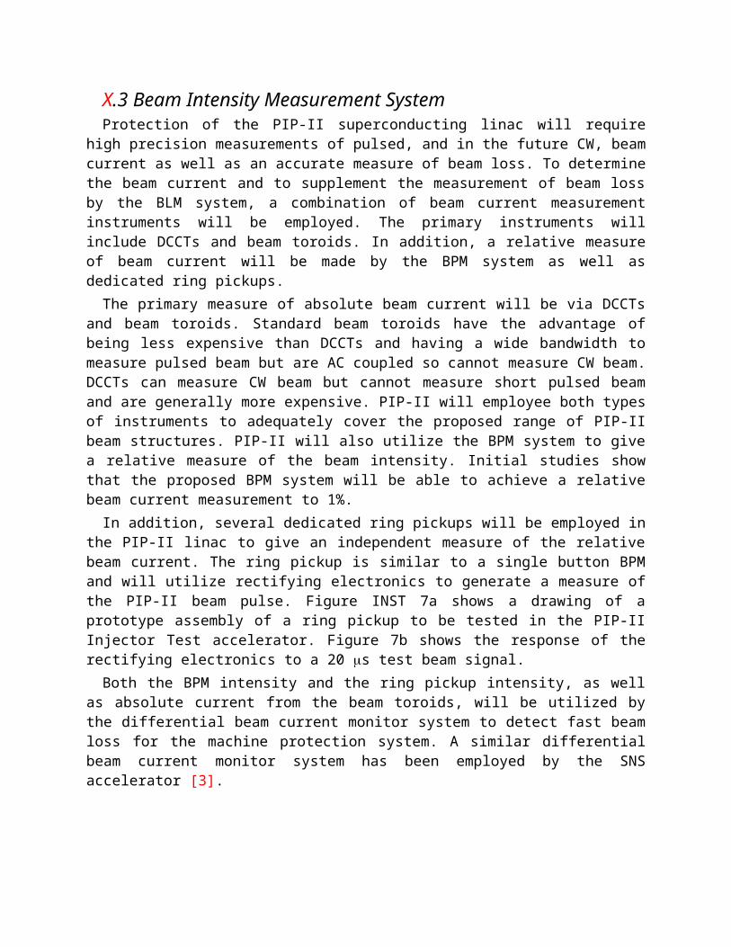
X.3 Beam Intensity Measurement SystemProtection of the PIP-II superconducting linac will require high precision measurements of
pulsed, and in the future CW, beam current as well as an accurate measure of beam loss. To determine the beam current and to supplement the measurement of beam loss by the BLM system, a combination of beam current measurement instruments will be employed. The primary instruments will include DCCTs and beam toroids. In addition, a relative measure of beam current will be made by the BPM system as well as dedicated ring pickups.
The primary measure of absolute beam current will be via DCCTs and beam toroids. Standard beam toroids have the advantage of being less expensive than DCCTs and having a wide bandwidth to measure pulsed beam but are AC coupled so cannot measure CW beam. DCCTs can measure CW beam but cannot measure short pulsed beam and are generally more expensive. PIP-II will employee both types of instruments to adequately cover the proposed range of PIP-II beam structures. PIP-II will also utilize the BPM system to give a relative measure of the beam intensity. Initial studies show that the proposed BPM system will be able to achieve a relative beam current measurement to 1%.
In addition, several dedicated ring pickups will be employed in the PIP-II linac to give an independent measure of the relative beam current. The ring pickup is similar to a single button BPM and will utilize rectifying electronics to generate a measure of the PIP-II beam pulse. Figure INST 7a shows a drawing of a prototype assembly of a ring pickup to be tested in the PIP-II Injector Test accelerator. Figure 7b shows the response of the rectifying electronics to a 20 s test beam signal.
Both the BPM intensity and the ring pickup intensity, as well as absolute current from the beam toroids, will be utilized by the differential beam current monitor system to detect fast beam loss for the machine protection system. A similar differential beam current monitor system has

been employed by the SNS accelerator [3].
Figure INST 7a. Drawing of a prototype ring pickup.
Figure INST 7b. Response of the ring pickup rectifying electronics to simulated 20 s 162.5 MHz test signal.
X.4 Beam Transverse Profile Measurement SystemWe are considering two types of transverse wire profiling methods for PIP-II. The first
method would use photo-disassociation of H- via laser and the second method would be a tradition wire scanner. Because of the minimal interaction with the beam, the laser-based profile monitor is our primary choice and will be used exclusively near superconducting sections of the linac. However, traditional wire scanners are a proven technology in accelerators and we will be considered as a backup choice for certain areas of the linac and 800 MeV transfer line. Table 3 shows the preliminary requirements for beam transverse profile measurements.
Parameter Units ValueSpatial resolution mm < 0.1Signal dynamic range > 103
Spatial range mm ± 15
Table 3. Preliminary requirements for beam transverse profile measurements.
X.4.1 Laser-based Transverse Profile MeasurementsPIP-II will utilize transverse laser profile monitors throughout the linac and 800 MeV
transport line. Laser-based transverse profile measurements of H- beam has been demonstrated by different groups [4-5]. SNS at Oak Ridge have implemented a laser-based profile measurements as part of their operations [6]. Traditionally, the technique of photo-disassociation (H- + Ho + e-) is accomplished with high peak power lasers and signal detection through the collection of electrons. However, SNS has demonstrated a longitudinal profile measurement in

their MEBT utilizing a low peak power laser with electron collection. A low peak power laser will produce far fewer photo-disassociations and, hence, a smaller signal. For PIP-II we will construct of a combined transverse and longitudinal H- beam profiling instrument utilizing a low peak power, high rep-rate fiber laser with optical fiber transport to the accelerator and synchronous signal detection. The system will detect this small signal through narrow-band synchronous detection of a modulated laser pulse train. Figure INST 8 shows a diagram of the proposed laser profile monitor. A prototype version will be test at the PIP-II Injector Test accelerator.
Figure INST 8. Proposed transverse and longitudinal beam profile system. This system utilizes a high rep-rate, picosecond, mode-locked laser (MLL) that is locked to the accelerator LLRF. The laser pulse train amplitude modulated by a variable RF signal that is asynchronous to the accelerator RF. The laser pulse train is then transported to the beam line via optical fiber and scanned across the beam. Reduced H- beam intensity detection is made with a downstream BPM, and the signal is measured with the synchronous lock-in detection. The system will include beam profile measurements with electron detection for profile verification. Longitudinal profile scans are measured by changing MLL phase relative to the LLRF. Drawing courtesy of R. Wilcox, LBNL [7].
X.4.2 Wire Scanner Transverse Profile MeasurementsWire scanner systems have been a tradition method used for transverse profile measurements
of beam. They have the advantage of being a fairly straight forward and understood technique. They have the disadvantage of invasive, causing beam loss, and also for being fairly slow. We
will utilize wire scanners as a secondary profile measurement method in the MEBT and the 800 MeV transport line. A prototype wire scanner will be tested in the PIP-II Injector Test accelerator.
X.5 Other Beam Measurement SystemParagraph starts here…
X.5.1 Beam Transverse Emittance MeasurementsTransverse emittance measurements are a highly useful and versatile tool for the tuning and
operation of an accelerator. There are various techniques that can be used to determine the transverses emittance. PIP-II will employee two types of emittance measurements that will provide transverse phase-space, (1) Allison-type emittance scanners and (2) laser-based emittance scanners.
In addition to these phase-space measurement techniques, PIP-II will also make rms emittance measurements utilizing quadrupole scans and transverse profile monitors. These rms measurements will occur at locations that can provide the necessary combination of focusing elements and profile monitors.
X.5.1.1 Allison-Type Emittance ScannersAn emittance scanner for intense low-energy ion beams, based on sweeping electric fields,
was proposed in 1983 [8]. This type of emittance scanner has been typically classified as an Allison-type transverse emittance scanner and they have been utilized for ion source and LEBT beam emittance measurements [9]. A functional representation of an Allison scanner illustrating the two slit design with electric field deflecting plates is shown in figure INST 9. PIP-II will utilize an Allison scanner for both the ion source/LEBT and also for the MEBT.
A water-cooled Allison scanner has been built and tested with the PIP-II Injector Test accelerator LEBT and ion source [10]. The scanner has been operated extensively for both pulsed and DC 30 keV H- beam up to 10 mA. Figure INST 10 shows a set of phase space measurements taken in the PIP-II Injector Test LEBT with this Allison scanner. This figure illustrates the capability of the Allison emittance scanner.
Figure INST 9. Pictorial representation of an Allison-type scanner with an illustration of the bending properties of the electric deflecting plates.

Figure INST 10. Example of the evolution of the transverse phase space taken in the LEBT of the PIP-Injector Test accelerator for a 2 ms pulsed, 5 mA H- beam with 0.125 ms time steps.
X.5.1.2 Laser-Based Emittance ScannersMeasurements of transverse phase space and emittance at the end of the PIP-II linac will be
made using a laser-based emittance scanner. A functional diagram of a laser-based emittance scanner is shown in figure INST 11. A laser-based scanner has the advantage of minimal beam interaction enabling it to make measurements for both pulsed and CW beam. A similar, but not identical, technique has been implemented at the SNS accelerator [11].
Figure INST 11. Functional diagram of a laser-based transverse emittance monitor.
X.5.2 Beam Longitudinal Profile MeasurementsThe PIP-II longitudinal rms bunch length changes from several hundred picoseconds in the
MEBT to as short as 4 picoseconds at the end of the linac. Measurement of the longitudinal profile for these non-relativistic short bunches can be difficult. As discussed earlier, PIP-II will utilize laser-based profiling for both transverse and longitudinal profile measurements. SNS has

demonstrated that laser-based longitudinal profile measurements are possible for MEBT beam [12].
However, laser-based longitudinal profiles become difficult when the beam bunch size is on the same order as the laser pulse length. Measurement of longitudinal profiles at the end of the linac will require laser pulse length of ~200 femtoseconds or less. While it is possible to generate these short laser pulses with sufficient power, it is difficult to transport the laser light without introducing dispersion effects. If laser-based measurements are not possible for very short bunch length measurements, PIP-II will explore other measurements options such as optical transition radiation techniques.
X.5.3 MEBT Chopper Extinction MeasurementsThe PIP-II MEBT chopper will be able to arbitrarily remove individual bunches from the
beam. The chopping efficiency of the removed bunches needs to be verified to a level of better than one part in 10-4. PIP-II will utilize a high-bandwidth resistive wall current monitor (RCWM) to measure the integrated filed produced by individual beam bunches. Integration of the RWCM signal is accomplished using a fast oscilloscope. This technique is similar to the Fermilab sampled bunch display systems used to measure longitudinal beam information of individual bunches in the Tevatron and Main Injector accelerators [13]. Figure INST 12 shows a block diagram of the proposed MEBT bunch extinction system.
Figure INST 12. Block diagram of the PIP-II MEBT extinction measurement system.
X.5.5 Beam Halo MeasurementsFor any superconducting accelerator, measurement and control of longitudinal and transverse
beam halo is important. Typical, beam halo measurements are defined at the level of 10-4 to 10-6
of the core beam [14]. This places a large dynamic range requirement for any halo measurement system.
For transverse beam halo measurements and control, PIP-II will primarily utilize electrically isolated scrapers in the MEBT. Prototype scrapers, with current readout, will be tested in the PIP-II Injector Test accelerator. Wire scanners will also be used to measure transverse beam halo but in order to protect the superconducting linac, wire scanners will be limited to operation in the MEBT and the 800 MeV transport line. Also, the LEBT and MEBT emittance scanners will be

utilized to make transverse tails and halo measurement.In addition, the laser-based profile monitors and will measure tails of bunch charge
distribution. However, the laser-based system is probably limited to sensitivity of ~10-3. Measurement of longitudinal bunch tails and halo is much more difficult. PIP-II will utilize laser-based profiling to measure bunch tails but is probably prevented from measuring longitudinal halo because of limited sensitivity.
References[1] A. Lunin, et al., “Development of a Low-Beta Button BPM for the PXIE Project,” TUPC14,
IBIC2013, Oxford, UK
[2] J. Crisp, et al.. ”Position and Phase Measurements of Microampere Beams at the Michigan State University REA3 Facility,” THPAC20, PAC2013, Pasadena, CA
[3] W. Blokland, C. Peters, “A New Differential and Errant Beam Current Monitor for the SNS Accelerator,” THAL2, IBIC2013, Oxford, UK
[4] R. Connolly, et al., “Beam-Energy and Laser Beam-Profile Monitor at the BNL Linac,” TUPSM011, BIW2010, Santa Fe, NM
[5] Y. Liu, et al., “Laser Based Diagnostics for Measuring H- Beam Parameters,” WEOCN1, PAC2011, New York, NY
[6] Y. Liu, et al., “Laser Applications: H- Beam Photo-Detachment and Push Button Diagnostics,” TUCP02, BIW2012, Newport News, VA
[7] R. B. Wilcox, et al., “A Low-Power Laser Wire with Fiber Optic Distribution,” TUPD53, DIPAC2011, Hamburg Germany
[8] P. W. Allison, et al., “An Emittance Scanner for Intense Low-Energy Ion Beams,” IEEE Transactions on Nuclear Science, Vol. NS-30 (1983)
[9] M. P. Stockli, et al., “Emittance Studies with an Allison Scanner,” Rev. Sci. Instrum. 77, 03B706 (2006)
[10] R. D’Arcy, et al., “Characterization of the PXIE Allison-type Emittance Scanner,” Nucl. Inst. A 815 (2016)
[11] Y. Liu, et al., “Laser Wire Based Transverse Emittance Measurements of H- Beam at Spallation Neutron Source,” MOPHA041, IPAC2015, Richmond, VA
[12] A. Zhukov, et al., “Longitudinal Laser Wire at SNS,” MOCYB3, IBIC2014, Monterey, CA
[13] R. Thurman-Keup, et al., “Longitudinal Bunch Monitoring at the Fermilab Tevatron and Min Injector Synchrotrons,” Jinst 6 T10004 (2011)

[14] A. Aleksandrox, “Beam Halo Characterization and Mitigation,” FRXBA01, IPAC2016, Busan, Korea