xi5 wireless edition - brunswick marine in...
TRANSCRIPT

© 2
014
Mer
cury
Mar
ine
Xi5
Wire
less
Edi
tion
90-8
M00
9054
6 51
4en
g

eng

ORIGINAL LANGUAGE INSTRUCTIONS
FCC and IC Compliance StatementXi5 WIRELESS FOOT PEDAL FCC ID ‑ MVU09291Xi5 WIRELESS REMOTE FCC ID ‑ MVU09305IC: 6094A‑09291, 6094A‑09305This device complies with part 15 of the FCC Rules. Operation is subject to thefollowing two conditions:1. This device may not cause harmful interference.2. This device must accept any interference received including interference
that may cause undesired operation.This device complies with FCC Rules.Changes or modifications not expressly approved by the party responsible forcompliance could void the user's authority to operate the equipment.This device complies with Industry Canada license‑exempt RSS standard(s).Operation is subject to the following two conditions: (1) this device may notcause interference, and (2) this device must accept any interference, includinginterference that may cause undesired operation of the device.Le présent appareil est conforme aux CNR d'Industrie Canada applicables auxappareils radio exempts de licence. L'exploitation est autorisée aux deuxconditions suivantes: (1) l'appareil ne doit pas produire de brouillage, et (2)l'utilisateur de l'appareil doit accepter tout brouillage radioélectrique subi, mêmesi le brouillage est susceptible d'en compromettre le fonctionnement.
N2523
EU Compliance StatementAttwood Corporation hereby declares that the MotorGuide Xi5 trolling motor isin compliance with the essential requirements and other relevant provisions ofthe 99/5/EC R&TTE directive.
CE DeclarationManufacturer: Attwood CorporationAddress: 1016 N. MonroeLowell, MI 49415 USATelephone: 616‑897‑9241Authorized Representative: Brunswick MarineParc Industriel de Petit‑RechainB‑4800Verviers, Belgium
eng i
Telephone: +32(0)87323222Product: MotorGuide Xi5 SeriesModel: includes all 12, 24, and 36 volt DC modelsCouncil Directive 1999/5/EC ‑ Radio and Telecommunications TerminalEquipment (R&TTE)• EN 300 440‑1 V1.6.1: EMC and Radio spectrum Matters; Short Range
Devices.• EN 301 489‑1 V1.9.2: EMC and Radio spectrum Matters; Radio
Equipment.Council Directive 2004/40/EC ‑ Health and Safety Requirements• EN 62311:2008 ‑ Assessment of electronic and electrical equipment
related to human exposure restrictions for electromagnetic fields.Council Directive 2004/108/EC ‑ Electromagnetic Compatibility• EN 55012:2008; A1:2010 ‑ Vehicles, boats and internal combustion
engines.Council Directive 98/96/EC ‑ Maritime Equipment Directive• EN 60945:2002+C1:2008 ‑ Maritime navigation and radiocom. equip.
(Motor systems)• CISPR16 ‑ Conducted and Radiated Emissions• EN61000‑4‑2:2008 ESD• EN61000‑4‑3:2006 Radiated Immunity• EN61000‑4‑4:2004 EFT• EN61000‑4‑5:2005 Surges• EN61000‑4‑6:2008 Conducted Susceptibility• EN61000‑4‑8:2001 Magnetic Field Immunity• EN6100‑4‑11:2004 Voltage Dips and Interrupts
Council Directive 2006/42/EC ‑ Machinery• EN ISO 12100 ‑ Safety of machinery ‑ General principles for design, risk
assessment and reductionAn official copy of the Declaration of Conformity can be found at http://www.motorguide.com/support/certifications.
ii eng
Environmental Compliance StatementAll MotorGuide products that are subject to the 2002/96/EC WEEE directive arecompliant with the WEEE marking requirement. Such products are marked withthe crossed‑out wheelie bin (WEEE symbol shown below) in accordance withEuropean Standard EN50419.
54539
The symbol on the product or its packaging indicates that this product must notbe disposed of with your other household waste. Instead, it is yourresponsibility to dispose of your waste equipment by handing it over to adesignated collection point for the recycling of waste electrical and electronicequipment. The separate collection and recycling of your waste equipment atthe time of disposal will help conserve natural resources and ensure that it isrecycled in a manner that protects human health and the environment. Formore information about where you can drop off your waste for recycling, pleasecontact your local authority, or where you purchased your product.
Important Operator Information
! ISO 7000‑0434B ‑ Caution symbolConsult this documentation in all cases where this symbol appears. Thissymbol is used to inform you of any potential HAZARD or actions thatrequire your attention.Use of this equipment in a manner other than that specified by AttwoodCorporation may compromise the design integrity and become unsafe.WARNING: This equipment is not intended for use in explosive environments.ADVERTENCIA: Este equipo no está diseñado para uso en atmósferasexplosivas.AVVERTIMENTO: Questa apparechiatura non è inteso per l'uso in ambientiesplosivi.WARNUNG: Das Ausrüstung darf in einer explosiven Umgebung NICHTverwendet werden.ADVERTISSEMENT: Cet équipement n'est pas prévu pour une utilisation dasdes environments explosifs.
Thank YouThank you for purchasing a MotorGuide Xi5 Wireless Trolling Motor.
eng iii

The Xi5 is designed and engineered to deliver the performance that anglersexpect: quiet operation, reliability, and precise control. We’re confident that theXi5 will enhance your fishing experience and we appreciate that you choseMotorGuide.Please take a moment to register your new Xi5 at motorguide.com—orcomplete and mail the enclosed Warranty Registration Card.
Warranty MessageThe product you have purchased comes with a Limited Warranty fromMotorGuide. The terms of the policy are set forth in the Warranty Informationsection of this manual. The policy statement contains a description of theduration of coverage, important disclaimers and limitations of damages,and other related information. Please review this important information.The description and specifications contained herein were in effect at the timethis manual was approved for printing. MotorGuide, whose policy is one ofcontinued improvement, reserves the right to discontinue models at any time, tochange specifications, designs, methods, or procedures without notice andwithout incurring obligation.MotorGuide, Lowell, Michigan U.S.A.Mercury MarineEagle and Lowrance are registered trademarks of Navico Inc. Garmin is aregistered trademark of Garmin Ltd. Humminbird is a registered trademark ofJohnson Outdoors Marine Electronics, Inc. Vexilar is a registered trademark ofVexilar, Inc.
Copyright and Trademark Information© MERCURY MARINE. All rights reserved. Reproduction in whole or inpart without permission is prohibited.Alpha, Axius, Bravo One, Bravo Two, Bravo Three, Circle M with Waves Logo,K‑planes, Mariner, MerCathode, MerCruiser, Mercury, Mercury with WavesLogo, Mercury Marine, Mercury Precision Parts, Mercury Propellers, MercuryRacing, MotorGuide, OptiMax, Quicksilver, SeaCore, Skyhook, SmartCraft,Sport‑Jet, Verado, VesselView, Zero Effort, Zeus, #1 On the Water and We'reDriven to win are registered trademarks of Brunswick Corporation. Pro XS is atrademark of Brunswick Corporation. Mercury Product Protection is a registeredservice mark of Brunswick Corporation.
iv eng

Warranty Information
MotorGuide Two Year Limited Warranty............................................................ 1
General Information and Component Identification
Component Identification.................................................................................... 4Recording the Serial Number............................................................................. 5Product Registration........................................................................................... 5Boater's Responsibilities..................................................................................... 6Protecting People in the Water........................................................................... 6Passenger Safety Message................................................................................ 6Safe Boating Suggestions.................................................................................. 6
Product Installation, Wiring, and Battery Information
Installing the Trolling Motor.................................................................................8Recommended Practice and Procedures......................................................... 12Battery Recommendations............................................................................... 12Battery Precautions.......................................................................................... 13Establishing a Common Ground....................................................................... 13Wire Color Code Abbreviations........................................................................ 14Battery Connection........................................................................................... 14Activating the Wireless Foot Pedal................................................................... 18Activating the Handheld Remote...................................................................... 18Connecting the Sonar Display to the Trolling Motor......................................... 19
Trolling Motor Operation
Status Indicator Light Identification................................................................... 21Stowing and Deploying the Trolling Motor........................................................ 21Adjusting the Motor Depth................................................................................ 25Foot Pedal Operation........................................................................................26Handheld Remote Operation............................................................................ 30
eng v

Maintenance and Storage
Trolling Motor Care........................................................................................... 32Inspection and Maintenance Schedule............................................................. 32Storage Preparation..........................................................................................34Battery Inspection............................................................................................. 35Propeller Replacement..................................................................................... 35
Owner Service Assistance
Troubleshooting................................................................................................ 38Troubleshooting the Foot Pedal and Handheld Remote...................................41Service Assistance........................................................................................... 44Mercury Marine Service Offices........................................................................45
vi eng

MotorGuide Two Year Limited WarrantyKEEP YOUR ORIGINAL PURCHASE RECEIPT OR BILL OF SALE.1. For recreational use customers, MotorGuide electric trolling motors are
warranted to the original retail purchaser to be free from defects inmaterial or workmanship for a period of two years from the date ofpurchase.
2. To obtain warranty service, the purchaser should deliver or return the unit(postage prepaid and insured) to any MotorGuide authorized servicedealer. DO NOT RETURN TO PLACE OF PURCHASE unless they arean authorized service center. Products returned by mail should becarefully packaged and include a note describing the nature of theproblem and/or service requested, customer address, and phone number.A copy of the receipt, bill of sale, registration verification or other proof ofpurchase is required with the return of the product for warrantyconsideration. Warranty claims will not be accepted without presentationof purchase receipt for the trolling motor, other verification of registration,or bill of sale for a boat package.
3. MotorGuide, at its discretion, will repair or replace items covered underthe terms of this warranty. Neither MotorGuide nor MotorGuide servicedealers are responsible for damages to MotorGuide products due torepairs performed by anyone other than an authorized MotorGuideservice dealer. Neither MotorGuide nor Attwood is responsible for failureor damage caused by improper installation, set‑up, preparation, orprevious service or repair errors.
4. For commercial use and government use customers, MotorGuide electrictrolling motors are warranted to the original retail purchaser to be freefrom defects in material or workmanship for one (1) year. Commercial useis defined as any work or employment‑related use of the product, or anyuse of the product which generates income, for any part of the warrantyperiod, even if the product is only occasionally used for such purposesuch as rental fleets, guides, fish camps or similar operations. Warranty isnot transferable to any subsequent purchaser. The Mercury ProductProtection plan is not available to commercial use or government usecustomers.
5. MotorGuide Composite Shaft Limited Lifetime Warranty. MotorGuidecomposite shafts are warranted to the original retail purchaser to be freeof defects in material or workmanship for the lifetime of the originalpurchaser. MotorGuide will provide a new composite shaft at no cost forany composite shaft which contains a defect in material or workmanship.The installation costs are the sole responsibility of the purchaser.
WARRANTY INFORMATION
eng 1
6. Warranty coverage is available to customers that purchase from anauthorized dealer or retailer that is authorized by MotorGuide Marine todistribute the product in the country in which the sale occurred. Warrantycoverage and duration varies by the country in which the owner resides.This Limited Warranty begins on the date the product is first sold to apurchaser or the date on which the product is first put into service,whichever occurs first. MotorGuide accessories are covered by thisLimited Warranty for a coverage period of one (1) year from the date ofretail sale. The repair or replacement of parts, or the performance ofservice under this warranty, does not extend the life of this warrantybeyond its original expiration date. Promotional warranties are notincluded in this statement and coverage may vary by promotion. Producteither sold or put into service more than six years from date ofmanufacture is excluded from warranty coverage.
7. This warranty does not apply to normal worn parts, for example, worncables, adjustments, or product damage due to: 1) neglect, lack ofmaintenance, accident, abnormal operation or improper installation orservice; 2) abuse, such as, bent metal columns, bent armature shafts,broken control cables, etc., accidents, modifications, misuse, excessivewear or damage caused by an owner’s failure to provide reasonable andnecessary installation or care; 3) use of an accessory or part notmanufactured by MotorGuide or Attwood; 4) alteration or removal of parts;5) opening the lower unit (motor) by anyone other than an authorizedMotorGuide service center will void this warranty.
8. We reserve the right to improve the design of any trolling motor withoutassuming any obligation to modify any trolling motor previouslymanufactured.
9. All serialized "Service‑Repair" trolling motors receive a (1) one yearwarranty. Non‑serialized "Service‑Repair" electric trolling motors are NOTwarranted. "Service‑Repair" motor denotes a trolling motor sold byMotorGuide that may be used, but has been inspected and may have hadminor repairs. Original retail purchaser of a "Service‑Repair" motor is thefirst purchaser of the motor after it is denoted as "Service‑Repair.""Service‑Repair" motors have a blue sticker on the battery cable and boxdenoting "Manufacturer Certified Service‑Repair Motor."
10. This warranty will not apply to: 1) haul‑out, launch, towing and storage,transportation charges and/or travel time, telephone or rental charges ofany type, inconvenience, or loss of time or income, or other consequentialdamages; or 2) removal or replacement of boat partitions or materialbecause of boat design for necessary access to the Product; or 3)disconnection and reconnection of hard‑wired trolling motors.
11. TERMINATION OF COVERAGE: Warranty coverage may be terminatedfor repossessed product, or product purchased at auction, from a salvageyard, from a liquidator, from an insurance company, from unauthorizedmarine dealers or boatbuilders, or other third party entities.
WARRANTY INFORMATION
2 eng

12. ALL INCIDENTAL OR CONSEQUENTIAL DAMAGES ARE EXCLUDEDFROM THIS WARRANTY, WARRANTIES OF MERCHANTABILITY ANDFITNESS ARE EXCLUDED FROM THIS WARRANTY, IMPLIEDWARRANTIES ARE LIMITED TO THE LIFE OF THIS WARRANTY.SOME STATES DO NOT ALLOW LIMITATIONS ON HOW LONG ANIMPLIED WARRANTY LASTS OR THE EXCLUSION OR LIMITATIONOF INCIDENTAL OR CONSEQUENTIAL DAMAGES, SO THE ABOVELIMITATIONS OR EXCLUSIONS MAY NOT APPLY TO YOU. THISWARRANTY GIVES YOU SPECIFIC LEGAL RIGHTS, AND YOU MAYALSO HAVE OTHER LEGAL RIGHTS WHICH MAY VARY FROMSTATE TO STATE.
For Your Records:Model Number _______________________________
Serial Number _______________________________
WARRANTY INFORMATION
eng 3

Component Identification
a - Headb - Curly cablec - Stow/deploy release leverd - Battery cables (hidden)e - Wireless foot pedalf - Handheld wireless remoteg - Deck mounth - Propelleri - Skegj - Lower unit (motor)k - Depth collarl - Depth collar knobm - Composite columnn - Steering transmission
53443
b
h
i
j
k
m
g e
d
a
nc
f
l
GENERAL INFORMATION AND COMPONENTIDENTIFICATION
4 eng

Recording the Serial NumberIt is important to record the serial number and model number for futurereference. The serial number tags are located on the trolling motor as shown.Record the serial number and the model number in the space provided in theWarranty Information section of this manual.
a - Model identification numberb - Serial number
Product RegistrationFor warranty purposes, please register your MotorGuide trolling motor bycompleting the enclosed warranty card or by visiting www.motorguide.com.
b
a
53462
GENERAL INFORMATION AND COMPONENTIDENTIFICATION
eng 5

Boater's ResponsibilitiesThe operator (driver) is responsible for the correct and safe operation of theboat and safety of its occupants and general public. It is strongly recommendedthat each operator (driver) read and understand this entire manual beforeoperating the trolling motor.Be sure at least one additional person on board is instructed in the basicoperation of the trolling motor in case the driver is unable to operate the boat.
Protecting People in the WaterWHILE YOU ARE TROLLINGIt is difficult for a person in the water to take quick action to avoid a boatheading in their direction, even at slow speeds.
21604
Always slow down and exercise extreme caution any time you are boating in anarea where there might be people in the water.
WHILE THE BOAT IS STATIONARY
! WARNINGA spinning propeller, a moving boat, or any solid device attached to the boatcan cause serious injury or death to swimmers. Stop the trolling motorimmediately whenever anyone in the water is near your boat.
Shut off the trolling motor before allowing people to swim or be in the waternear your boat.
Passenger Safety MessageWhenever the boat is in motion, observe the location of all passengers. Asudden reduction in boat speed, such as a sharp change of boat direction,could throw them off the boat.
Safe Boating SuggestionsIn order to safely enjoy the waterways, familiarize yourself with local and othergovernmental boating regulations and restrictions, and consider the followingsuggestions.Use flotation devices. It is the law to have an approved personal flotationdevice of suitable size for each person aboard and have it readily accessible.
GENERAL INFORMATION AND COMPONENTIDENTIFICATION
6 eng
Do not overload your boat. Most boats are rated and certified for maximumload (weight) capacities, refer to your boat capacity plate. If in doubt, contactyour dealer or the boat's manufacturer.Perform safety checks and required maintenance. Follow a regularschedule and ensure all repairs are made properly.Never be under the influence of alcohol or drugs while boating (it is thelaw). Alcohol or drug use impairs your judgment and greatly reduces yourability to react quickly.Passenger boarding. Stop the trolling motor whenever passengers areboarding or unloading.Maximum sound level. Trolling motor sound pressure levels do not exceed 70dB(A).Be alert. The operator of the boat is responsible by law to maintain a properlookout by sight and hearing. The operator must have an unobstructed viewparticularly to the front. No passengers, load, or fishing seats should block theoperator's view when operating the boat.Underwater hazards. Reduce speed and proceed with caution whenevernavigating in shallow water.Tripping hazards. To avoid a trip hazard, route all cables and wiring neatlyand out of the way.Report accidents. Boat operators are required by law to file a BoatingAccident Report with their state boating law enforcement agency when theirboat is involved in certain boating accidents. A boating accident must bereported if 1) there is loss of life or probable loss of life, 2) there is personalinjury requiring medical treatment beyond first aid, 3) there is damage to boatsor other property where the damage value exceeds $500.00 or 4) there iscomplete loss of the boat. Seek further assistance from local law enforcement.
GENERAL INFORMATION AND COMPONENTIDENTIFICATION
eng 7

Installing the Trolling Motor1. Remove the two side panel screws from each side of the deck mount.
Gently pull the side panels away from the deck mount, taking care not todamage the locating tabs, and remove the side panels from both sides ofthe trolling motor.
a - Side panel screwsb - Locating tab
2. If you are replacing an existing MotorGuide or competitive brand trollingmotor on your current boat, check if the existing mounting holes align withthe new deck mount before drilling new holes. Ensure that the mountinglocation meets the requirements listed in Step 4.
3. If new holes are not required to mount the trolling motor, skip ahead toStep 7.
4. Carefully select an appropriate area on the deck of the boat close to thecenterline to install the trolling motor. Ensure that the forward mountingbolts will not penetrate the hull. Have an assistant hold the trolling motorin position while the mounting location is being selected.
IMPORTANT: The mounting position must be tested in the stowed anddeployed positions before drilling the mounting holes.IMPORTANT: Choose an area on the deck with 10.2 cm (4.0 in.) of clearancebetween the bow of the boat and the deck mount to prevent interferencebetween the trolling motor and the bow roller when loading or unloading on asteep ramp.IMPORTANT: Ensure that the head does not protrude beyond the beam of theboat when in the stowed position.
a a53446
b
PRODUCT INSTALLATION, WIRING, AND BATTERYINFORMATION
8 eng
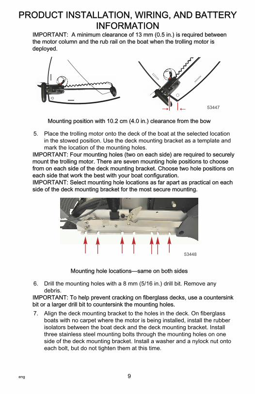
IMPORTANT: A minimum clearance of 13 mm (0.5 in.) is required betweenthe motor column and the rub rail on the boat when the trolling motor isdeployed.
53447
Mounting position with 10.2 cm (4.0 in.) clearance from the bow
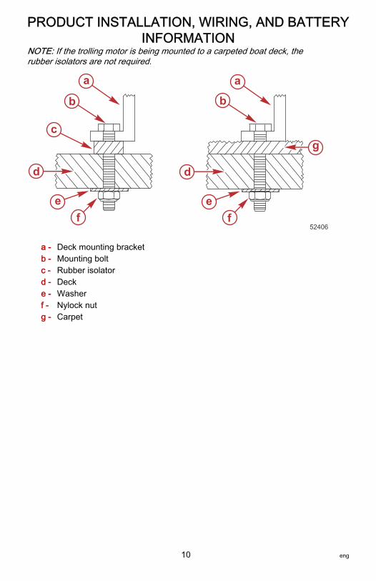
5. Place the trolling motor onto the deck of the boat at the selected locationin the stowed position. Use the deck mounting bracket as a template andmark the location of the mounting holes.
IMPORTANT: Four mounting holes (two on each side) are required to securelymount the trolling motor. There are seven mounting hole positions to choosefrom on each side of the deck mounting bracket. Choose two hole positions oneach side that work the best with your boat configuration.IMPORTANT: Select mounting hole locations as far apart as practical on eachside of the deck mounting bracket for the most secure mounting.
53448
Mounting hole locations—same on both sides
6. Drill the mounting holes with a 8 mm (5/16 in.) drill bit. Remove anydebris.
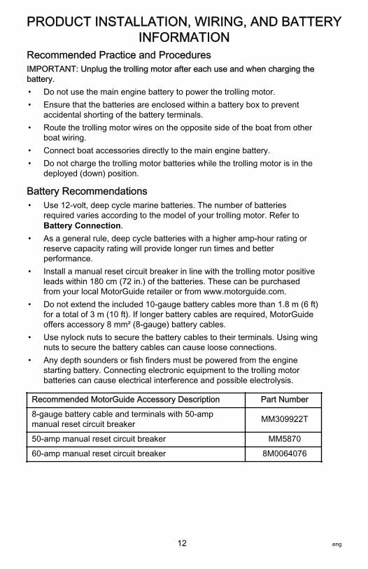
IMPORTANT: To help prevent cracking on fiberglass decks, use a countersinkbit or a larger drill bit to countersink the mounting holes.7. Align the deck mounting bracket to the holes in the deck. On fiberglass
boats with no carpet where the motor is being installed, install the rubberisolators between the boat deck and the deck mounting bracket. Installthree stainless steel mounting bolts through the mounting holes on oneside of the deck mounting bracket. Install a washer and a nylock nut ontoeach bolt, but do not tighten them at this time.
PRODUCT INSTALLATION, WIRING, AND BATTERYINFORMATION
eng 9
NOTE: If the trolling motor is being mounted to a carpeted boat deck, therubber isolators are not required.
a - Deck mounting bracketb - Mounting boltc - Rubber isolatord - Decke - Washerf - Nylock nutg - Carpet
a
b
c
d
ef
a
b
d
ef
g
52406
PRODUCT INSTALLATION, WIRING, AND BATTERYINFORMATION
10 eng

8. Grab onto the motor column and raise the unbolted side of the deckmounting bracket. Install the bolts through the deck mounting holes whileholding the deck mounting bracket at an angle. Holding the deckmounting bracket at an angle allows the bolts to be installed with lessinterference from the foot release mechanism. Install a washer and anylock nut onto each bolt.
53451
9. Align the trolling motor with the mounting holes in the deck. Hold themounting bolts securely with a 7/16 in. wrench while using a wrench orsocket to tighten the nylock nuts on both sides of the deck mountingbracket from under the deck.
10. Install the side panels onto the trolling motor, taking care not to damagethe locating tabs. Install the side panel screws.
a - Side panel screwsb - Locating tab
a a53446
b
PRODUCT INSTALLATION, WIRING, AND BATTERYINFORMATION
eng 11
Recommended Practice and ProceduresIMPORTANT: Unplug the trolling motor after each use and when charging thebattery.• Do not use the main engine battery to power the trolling motor.• Ensure that the batteries are enclosed within a battery box to prevent
accidental shorting of the battery terminals.• Route the trolling motor wires on the opposite side of the boat from other
boat wiring.• Connect boat accessories directly to the main engine battery.• Do not charge the trolling motor batteries while the trolling motor is in the
deployed (down) position.
Battery Recommendations• Use 12‑volt, deep cycle marine batteries. The number of batteries
required varies according to the model of your trolling motor. Refer toBattery Connection.
• As a general rule, deep cycle batteries with a higher amp‑hour rating orreserve capacity rating will provide longer run times and betterperformance.
• Install a manual reset circuit breaker in line with the trolling motor positiveleads within 180 cm (72 in.) of the batteries. These can be purchasedfrom your local MotorGuide retailer or from www.motorguide.com.
• Do not extend the included 10‑gauge battery cables more than 1.8 m (6 ft)for a total of 3 m (10 ft). If longer battery cables are required, MotorGuideoffers accessory 8 mm² (8‑gauge) battery cables.
• Use nylock nuts to secure the battery cables to their terminals. Using wingnuts to secure the battery cables can cause loose connections.
• Any depth sounders or fish finders must be powered from the enginestarting battery. Connecting electronic equipment to the trolling motorbatteries can cause electrical interference and possible electrolysis.
Recommended MotorGuide Accessory Description Part Number
8‑gauge battery cable and terminals with 50‑ampmanual reset circuit breaker MM309922T
50‑amp manual reset circuit breaker MM5870
60‑amp manual reset circuit breaker 8M0064076
PRODUCT INSTALLATION, WIRING, AND BATTERYINFORMATION
12 eng

Battery Precautions
! WARNINGAn operating or charging battery produces gas that can ignite and explode,spraying out sulfuric acid, which can cause severe burns. Ventilate the areaaround the battery and wear protective equipment when handling or servicingbatteries.
When charging batteries, an explosive gas mixture forms in each cell. Part ofthis gas escapes through holes in the vent plugs and may form an explosiveatmosphere around the battery if ventilation is poor. This explosive gas mayremain in or around the battery for several hours after it has been charged.Sparks or flames can ignite this gas and cause an internal explosion, whichmay shatter the battery.The following precautions should be observed to prevent an explosion:1. Do not smoke near batteries being charged or which have been charged
recently.2. Do not break live circuits at the battery terminals, because a spark usually
occurs at the point where a live circuit is broken. Always be careful whenconnecting or disconnecting cable clamps on chargers. Poor connectionsare a common cause of electrical arcs, which cause explosions.
3. Do not reverse the polarity of battery terminal to cable connections.
Establishing a Common GroundA common ground (–) connection increases sonar sensitivity, improves sonardisplay, avoids the ground circuit as a possible source of corrosion orelectrolysis, and reduces interference with other electronic equipment. For12‑volt trolling motor applications, connect the negative (–) terminal on thetrolling motor battery to the negative (–) terminal on the engine starting batterywith a common ground cable to establish a common ground.For 24‑volt and 36‑volt trolling motors, a common ground (–) connection cannotbe established with the 12‑volt electrical system in the boat due to the differentcircuit voltages. As a general rule to reduce interference with other electronicson your boat, route all battery wiring away from other boat wiring (opposite sideof the boat if possible), keep the battery cable length as short as possible, andalways use battery cables of the appropriate size (gauge).
ELECTROLYSISUsing the main engine battery as a power source for the trolling motor maycause electrolysis on metallic parts. If the motor and battery wiring are installedcorrectly and electrolysis issues continue, separate the trolling motor from anyother boat electronics. Using the main engine battery as a power source for thetrolling motor is not recommended. Refer to Battery Connection for correctinstallation.
PRODUCT INSTALLATION, WIRING, AND BATTERYINFORMATION
eng 13

Wire Color Code Abbreviations
Wire Color Abbreviations
BLK Black
BLU Blue
BRN Brown GRY Gray
GRN Green ORN or ORG Orange
PNK Pink PPL or PUR Purple
RED Red TAN Tan
WHT White YEL Yellow
LT or LIT Light DK or DRK Dark
Battery Connection
! WARNINGBefore working around electrical system components, disconnect the batterycables from the battery to prevent injury or damage to the electrical systemdue to an accidental short circuit.
! CAUTIONDisconnecting or connecting the battery cables in the incorrect order cancause injury from electrical shock or can damage the electrical system.Always disconnect the negative (‑) battery cable first and connect it last.
NOTICEFailure to operate the trolling motor within the recommended voltagespecifications can cause product damage. Do not exceed the maximumsupply voltage.
IMPORTANT: Refer to the decal on the head of the trolling motor to determinethe voltage requirements of your trolling motor.
12-VOLT BATTERY CONNECTION1. Starting with the negative (–) lead, disconnect the battery cables from the
engine starting battery.2. Install a 50‑amp (good) or 60‑amp (best) manual reset circuit breaker in
line with the trolling motor power cable positive (+) lead and the trollingmotor battery positive (+) terminal.
3. Connect the positive (+) trolling motor lead to the positive (+) trollingmotor battery terminal.
4. Connect the negative (–) trolling motor lead to the negative (–) trollingmotor battery terminal.
PRODUCT INSTALLATION, WIRING, AND BATTERYINFORMATION
14 eng
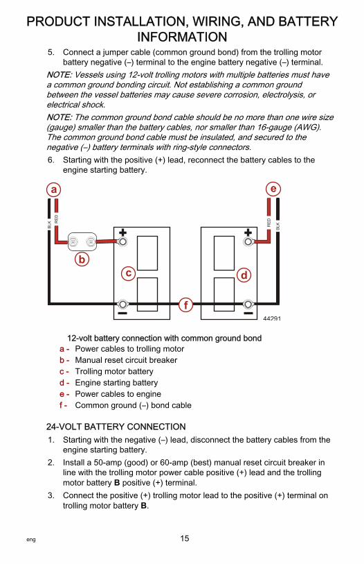
5. Connect a jumper cable (common ground bond) from the trolling motorbattery negative (–) terminal to the engine battery negative (–) terminal.
NOTE: Vessels using 12‑volt trolling motors with multiple batteries must havea common ground bonding circuit. Not establishing a common groundbetween the vessel batteries may cause severe corrosion, electrolysis, orelectrical shock.NOTE: The common ground bond cable should be no more than one wire size(gauge) smaller than the battery cables, nor smaller than 16‑gauge (AWG).The common ground bond cable must be insulated, and secured to thenegative (–) battery terminals with ring‑style connectors.6. Starting with the positive (+) lead, reconnect the battery cables to the
engine starting battery.
12-volt battery connection with common ground bonda - Power cables to trolling motorb - Manual reset circuit breakerc - Trolling motor batteryd - Engine starting batterye - Power cables to enginef - Common ground (–) bond cable
24-VOLT BATTERY CONNECTION1. Starting with the negative (–) lead, disconnect the battery cables from the
engine starting battery.2. Install a 50‑amp (good) or 60‑amp (best) manual reset circuit breaker in
line with the trolling motor power cable positive (+) lead and the trollingmotor battery B positive (+) terminal.
3. Connect the positive (+) trolling motor lead to the positive (+) terminal ontrolling motor battery B.
RE
D
BLK
BLKR
ED
RE
D
a
bc d
e
44291
f
PRODUCT INSTALLATION, WIRING, AND BATTERYINFORMATION
eng 15

4. Connect a jumper wire (reference gray) between the negative (–) terminalon battery B to the positive (+) terminal on battery A.
IMPORTANT: The jumper wire should be the same wire gauge as thenegative (–) and positive (+) power cables.5. Connect the trolling motor negative (–) lead to the negative (–) terminal on
battery A.6. Starting with the positive (+) lead, reconnect the battery cables to the
engine starting battery.
24-volt battery connectiona - Power cables to trolling motorb - Manual reset circuit breakerc - Jumper wire (not supplied)d - Negative (–) battery terminal
IMPORTANT: Do not connect a common ground bond cable between 24‑voltand 12‑volt electrical circuits.
36-VOLT BATTERY CONNECTION1. Starting with the negative (–) lead, disconnect the battery cables from the
engine starting battery.2. Install a 50‑amp (good) or 60‑amp (best) manual reset circuit breaker in
line with the trolling motor power cable positive (+) lead and the trollingmotor battery C positive (+) terminal.
3. Connect the positive (+) trolling motor lead to the positive (+) terminal ontrolling motor battery C.
RE
D
BLACK
a
bc
d
37824
GRAY
cBattery A
Battery B
PRODUCT INSTALLATION, WIRING, AND BATTERYINFORMATION
16 eng

4. Connect a jumper wire (reference gray) between the negative (–) terminalon battery C to the positive (+) terminal on battery B.
IMPORTANT: The jumper wire should be the same wire gauge as thenegative (–) and positive (+) power cables.5. Connect a jumper wire (reference gray) between the negative (–) terminal
on battery B to the positive (+) terminal on battery A.6. Connect the trolling motor negative (–) lead to the negative (–) terminal on
battery A.7. Starting with the positive (+) lead, reconnect the battery cables to the
engine starting battery.
36-volt battery connectiona - Power cables to trolling motorb - Manual reset circuit breakerc - Jumper wire (not supplied)d - Negative (–) battery terminal
IMPORTANT: Do not connect a common ground bond cable between 36‑voltand 12‑volt electrical circuits.
RE
D
BLK
37825
GRY
cBattery B
Battery C
Battery A
GRY
c
a
bc
d
PRODUCT INSTALLATION, WIRING, AND BATTERYINFORMATION
eng 17
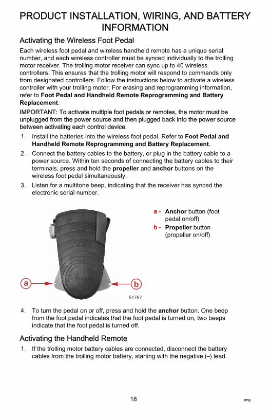
Activating the Wireless Foot PedalEach wireless foot pedal and wireless handheld remote has a unique serialnumber, and each wireless controller must be synced individually to the trollingmotor receiver. The trolling motor receiver can sync up to 40 wirelesscontrollers. This ensures that the trolling motor will respond to commands onlyfrom designated controllers. Follow the instructions below to activate a wirelesscontroller with your trolling motor. For erasing and reprogramming information,refer to Foot Pedal and Handheld Remote Reprogramming and BatteryReplacement.IMPORTANT: To activate multiple foot pedals or remotes, the motor must beunplugged from the power source and then plugged back into the power sourcebetween activating each control device.1. Install the batteries into the wireless foot pedal. Refer to Foot Pedal and
Handheld Remote Reprogramming and Battery Replacement.2. Connect the battery cables to the battery, or plug in the battery cable to a
power source. Within ten seconds of connecting the battery cables to theirterminals, press and hold the propeller and anchor buttons on thewireless foot pedal simultaneously.
3. Listen for a multitone beep, indicating that the receiver has synced theelectronic serial number.
a - Anchor button (footpedal on/off)
b - Propeller button(propeller on/off)
4. To turn the pedal on or off, press and hold the anchor button. One beepfrom the foot pedal indicates that the foot pedal is turned on, two beepsindicate that the foot pedal is turned off.
Activating the Handheld Remote1. If the trolling motor battery cables are connected, disconnect the battery
cables from the trolling motor battery, starting with the negative (–) lead.
a b51767
PRODUCT INSTALLATION, WIRING, AND BATTERYINFORMATION
18 eng

2. Connect the battery cables to the battery or plug in the battery cable to apower source. Within ten seconds of connecting the battery cables to theirterminals, press and hold the left arrow button and right arrow button onthe handheld remote simultaneously.
3. Listen for a multitone beep, which indicates that the receiver has storedthe electronic serial number.
a - + button—increasespeed
b - Propeller button—propeller on/off
c - Right arrow button—steer right
d - – button—decreasespeed
e - Left arrow button—steer left
Connecting the Sonar Display to the Trolling MotorNOTE: This procedure applies only to models equipped with integrated sonar.This sonar display connection procedure applies to trolling motor models withintegrated sonar that offer built‑in 200/83 kHz sonar transducers compatiblewith Eagle, Garmin, Humminbird, Lowrance, and Vexilar brand sonar displays.For compatibility with other sonar units, refer to www.motorguide.com.
51842
b
a
c
d
e
PRODUCT INSTALLATION, WIRING, AND BATTERYINFORMATION
eng 19
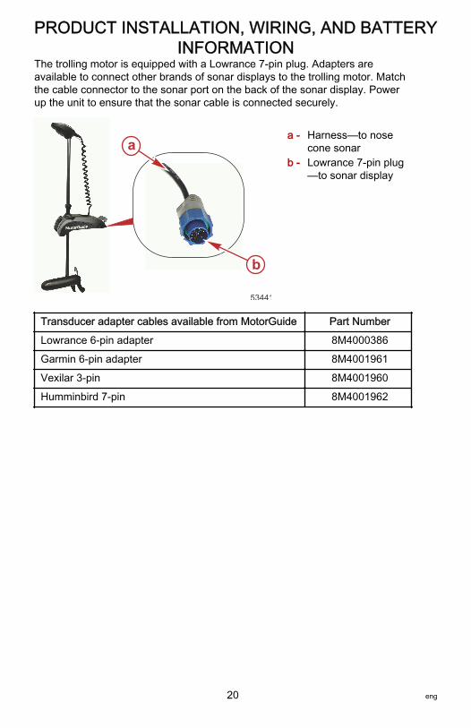
The trolling motor is equipped with a Lowrance 7‑pin plug. Adapters areavailable to connect other brands of sonar displays to the trolling motor. Matchthe cable connector to the sonar port on the back of the sonar display. Powerup the unit to ensure that the sonar cable is connected securely.
a - Harness—to nosecone sonar
b - Lowrance 7‑pin plug—to sonar display
Transducer adapter cables available from MotorGuide Part Number
Lowrance 6‑pin adapter 8M4000386
Garmin 6‑pin adapter 8M4001961
Vexilar 3‑pin 8M4001960
Humminbird 7‑pin 8M4001962
53441
a
b
PRODUCT INSTALLATION, WIRING, AND BATTERYINFORMATION
20 eng

Status Indicator Light IdentificationThis trolling motor is equipped with a multifunction status indicator light panel. Itcan display the status of the motor, propeller, battery charge, and GPS statusfor quick and easy reference during operation.
a - Power on/off indicator lightb - Propeller on/off indicator lightc - GPS navigation indicator
lightd - Battery status light
Stowing and Deploying the Trolling Motor
! WARNINGRotating propellers can cause serious injury or death. Never start or operatethe motor out of water.
! CAUTIONMoving parts, such as hinges and pivot points, can cause serious injury.Keep away from moving parts when stowing, deploying, or tilting the motor.
a
b c
d
51836
TROLLING MOTOR OPERATION
eng 21

STOWING THE TROLLING MOTOR1. Press down on the stow/deploy release lever with one hand or one foot.
Firmly grasp the column with one hand and tilt the trolling motor towardsthe mount.
53452
TROLLING MOTOR OPERATION
22 eng

2. Raise the motor out of the water and rotate the column so the lower unit isaligned with the mount cradle. Orient the lower unit so the cable does notwrap around the trolling motor column. Slide the lower unit into the mountcradle and release the stow/deploy release lever. The mount will lock thetrolling motor in the stowed position.
a - Lower unit (motor)b - Depth collarc - Columnd - Curly cablee - Stow/deploy release leverf - Mount cradle
3. Slide the depth collar tightly against the steering transmission. Rotate thedepth collar until it engages the steering transmission, then tighten thedepth collar knob.
a - Steering transmissionb - Depth collarc - Depth collar knob
NOTE: Optional mounts are available for supporting the trolling motor inextremely rough boating conditions.
a b
de
f 53458
c
a
c
51780
b
TROLLING MOTOR OPERATION
eng 23
Recommended MotorGuide Accessory Description Part Number
Standard Ram® mount stabilizer 8M4000977
Long Ram® mount stabilizer 8M4000978
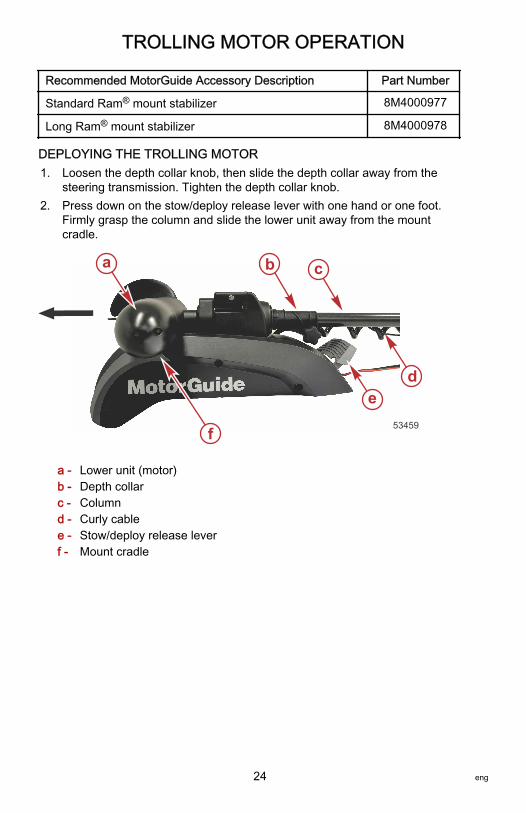
DEPLOYING THE TROLLING MOTOR1. Loosen the depth collar knob, then slide the depth collar away from the
steering transmission. Tighten the depth collar knob.2. Press down on the stow/deploy release lever with one hand or one foot.
Firmly grasp the column and slide the lower unit away from the mountcradle.
a - Lower unit (motor)b - Depth collarc - Columnd - Curly cablee - Stow/deploy release leverf - Mount cradle
a b
de
f 53459
c
TROLLING MOTOR OPERATION
24 eng
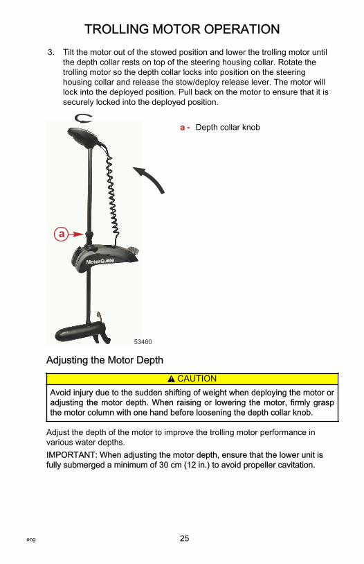
3. Tilt the motor out of the stowed position and lower the trolling motor untilthe depth collar rests on top of the steering housing collar. Rotate thetrolling motor so the depth collar locks into position on the steeringhousing collar and release the stow/deploy release lever. The motor willlock into the deployed position. Pull back on the motor to ensure that it issecurely locked into the deployed position.
a - Depth collar knob
Adjusting the Motor Depth
! CAUTIONAvoid injury due to the sudden shifting of weight when deploying the motor oradjusting the motor depth. When raising or lowering the motor, firmly graspthe motor column with one hand before loosening the depth collar knob.
Adjust the depth of the motor to improve the trolling motor performance invarious water depths.IMPORTANT: When adjusting the motor depth, ensure that the lower unit isfully submerged a minimum of 30 cm (12 in.) to avoid propeller cavitation.
53460
a
TROLLING MOTOR OPERATION
eng 25

1. Firmly grasp the column with one hand while loosening the depth collarknob so the column moves freely.
a - Depth collar knobb - Depth collar
2. Raise or lower the column to the desired depth. Tighten the depth collarknob to secure the column.
Foot Pedal Operation
! WARNINGRotating propellers can cause serious injury or death. Never start or operatethe motor out of water.
! WARNINGAvoid possible serious injury from unexpected acceleration and boatmovement when activating the trolling motor. When using the foot‑pedal, themotor will start up at the last selected speed and course settings. Beforepressing the foot‑pedal, hold on to a seat or handhold, and advisepassengers to do the same.
a
b
53461
TROLLING MOTOR OPERATION
26 eng

To operate the trolling motor using the foot pedal, sync the foot pedal to thetrolling motor receiver. Refer to Activating the Wireless Foot Pedal in theProduct Installation, Wiring, and Battery Information section of this manual.
a - Toe‑down position—right turn
b - Propeller momentaryon/off
c - Propeller constanton/off
d - Heel‑down position—left turn
e - Anchor button—models with GPSinstalled; also footpedal on/off
f - Speed control dial
TURNING THE FOOT PEDAL ON OR OFFPress and hold the anchor button. One short beep from the foot pedalindicates that the foot pedal is turned on; two short beeps indicate that the footpedal is turned off.
ce
f
a
b
51747
d
TROLLING MOTOR OPERATION
eng 27
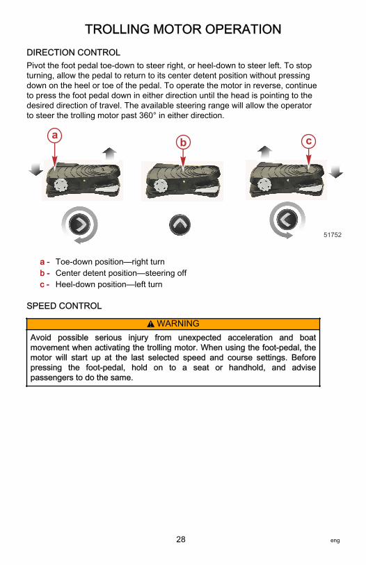
DIRECTION CONTROLPivot the foot pedal toe‑down to steer right, or heel‑down to steer left. To stopturning, allow the pedal to return to its center detent position without pressingdown on the heel or toe of the pedal. To operate the motor in reverse, continueto press the foot pedal down in either direction until the head is pointing to thedesired direction of travel. The available steering range will allow the operatorto steer the trolling motor past 360° in either direction.
a - Toe‑down position—right turnb - Center detent position—steering offc - Heel‑down position—left turn
SPEED CONTROL
! WARNINGAvoid possible serious injury from unexpected acceleration and boatmovement when activating the trolling motor. When using the foot‑pedal, themotor will start up at the last selected speed and course settings. Beforepressing the foot‑pedal, hold on to a seat or handhold, and advisepassengers to do the same.
51752
a cb
TROLLING MOTOR OPERATION
28 eng

Control the speed of the trolling motor by adjusting the speed control dial on thefoot pedal. Rotate the dial forward to increase motor speed, and rotate itbackward to reduce speed. Press and hold the momentary button to operatethe motor at the selected speed. Release the momentary button to stop themotor. Press the propeller constant on/off button once to run the motor at theselected speed. Press the button again to turn the motor off. The motor speedcan be adjusted while the motor is running.
a - Speed control dial—rotate forward toincrease speed
b - Momentary buttonc - Propeller constant
on/off button
ba
c
51753
TROLLING MOTOR OPERATION
eng 29

Handheld Remote Operation
! WARNINGRotating propellers can cause serious injury or death. Never start or operatethe motor out of water.
To operate the trolling motor using the handheld remote, sync the foot pedal tothe trolling motor receiver. Refer to Activating the Handheld Remote in theProduct Installation, Wiring, and Battery Information section of this manual.
a - Increase speedb - Propeller on/offc - Right turnd - Decrease speede - Left turn
TURNING THE HANDHELD REMOTE ON OR OFFThe handheld remote is always on, and is ready for use anytime that the trollingmotor is powered up and in the deployed position.
STEERING• To turn left, press the left turn button on the handheld remote.• To turn right, press the right turn button on the handheld remote.• The available steering range allows the trolling motor to turn beyond 360°
for operation in reverse.
SPEED CONTROL• Press the propeller on/off button once to start the propeller, and press
the propeller on/off button again to stop the propeller.
51842
b
a
c
d
e
TROLLING MOTOR OPERATION
30 eng

• The system is equipped with 20 speed levels. Press the increase speed(+) button to increase motor speed by one level, and press the decreasespeed (–) button to reduce motor speed by one level.
• Holding the increase speed (+) or decrease speed (–) will cause thespeed level to increase or decrease until the speed level limit is reached.Holding the increase speed (+) or decrease speed (–) button for 2.5seconds will ramp up the speed level from 0% to 100%, or decrease from100% to 0%, respectively. The trolling motor will emit two beeps when itreaches the 100% or 0% speed level.
TROLLING MOTOR OPERATION
eng 31

Trolling Motor CareTo keep your trolling motor in the best operating condition and retain itsdependability, your trolling motor must receive periodic inspections andmaintenance. Keep it maintained properly to ensure the safety of you and yourpassengers.
! WARNINGNeglecting to inspect, maintain, or repair your trolling motor can result inproduct damage or serious injury or death. Do not perform maintenance orservice on your trolling motor if you are not familiar with the correct serviceand safety procedures.
Record all maintenance performed and save maintenance work orders andreceipts.
SELECTING REPLACEMENT PARTSUse only original MotorGuide replacement parts.
Inspection and Maintenance ScheduleBEFORE EACH USE• Inspect for loose or corroded wiring connections.• Check the tightness of the battery cable connections. Nylock nuts are
recommended for securing the battery cables to their terminals.• Check the tightness of the propeller nut.• Check the propeller blades for damage.• Check the tightness of the mount to the deck of the boat.
AFTER EACH USE• Disconnect the battery cables from the power source or unplug the motor
from the boat.• Check each side of the propeller and propeller shaft for debris such as
weeds and fishing line. Remove all debris.• Check the tightness of the propeller nut.• Wash the trolling motor with clean water and a mild soap such as
Attwood® Premium Boat Wash to remove dirt and dust that may scratchthe surface.
IMPORTANT: Do not use harsh cleaners such as bleach or citrus cleaners toclean the trolling motor. These cleaners can damage the finish on the trollingmotor.IMPORTANT: Do not power wash the trolling motor.
EVERY 100 HOURS OF USE OR ANNUALLY (WHICHEVER OCCURSFIRST)1. Apply 2‑4‑C with PTFE to the depth collar knob screw threads.
MAINTENANCE AND STORAGE
32 eng
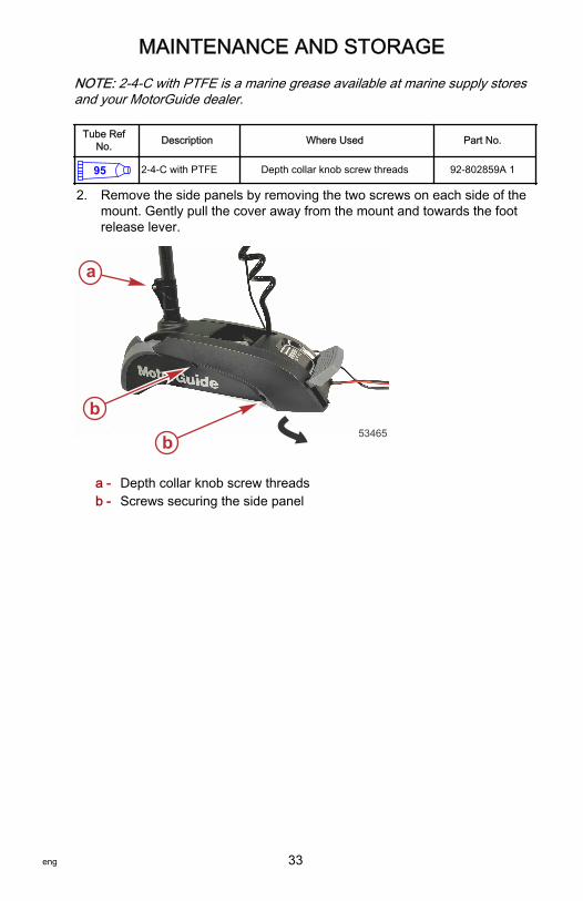
NOTE: 2‑4‑C with PTFE is a marine grease available at marine supply storesand your MotorGuide dealer.
Tube RefNo. Description Where Used Part No.
95 2-4-C with PTFE Depth collar knob screw threads 92-802859A 1
2. Remove the side panels by removing the two screws on each side of themount. Gently pull the cover away from the mount and towards the footrelease lever.
a - Depth collar knob screw threadsb - Screws securing the side panel
b
b 53465
a
MAINTENANCE AND STORAGE
eng 33

3. Apply 2‑4‑C with PTFE to the slot on the foot release lever linkage oneach side of the deck mount. Press the foot release lever and apply more2‑4‑C with PTFE to the slot, equally distributing the grease along thelength of the slot.
a - Slot
IMPORTANT: Never use an aerosol lubricant or solvent‑based lubricant togrease or oil any part of the trolling motor. Many aerosol lubricants containharmful propellants that can cause damage to various parts of the trollingmotor.
Tube RefNo. Description Where Used Part No.
95 2-4-C with PTFE Slot on the foot release lever linkage 92-802859A 1
4. Install the side panels onto the deck mount and tighten the screws.5. Check the tightness of the mounting screws, nuts, and other fasteners.6. Inspect the battery. Refer to Battery Inspection.
Storage PreparationThe major consideration in preparing your trolling motor for storage is to protectit from corrosion and damage caused by freezing of trapped water. It is alsorecommended that batteries are disconnected prior to storage and that thebatteries are stored indoors in a dry location during long‑term storage. Thebatteries should also be removed from the handheld remote and wireless footpedal for long‑term storage.
a53466
MAINTENANCE AND STORAGE
34 eng

Refer to the Inspection and Maintenance Schedule and complete theappropriate care instructions to prepare your trolling motor for storage. Storethe trolling motor in a dry location where it will not be affected by temperaturesbelow –29 °C (–20 °F).IMPORTANT: Trolling motors stored in temperatures below 0 °C (32 °F) shouldbe operated slowly for a minimum of 15 minutes before going above 30%throttle.
Battery InspectionThe battery should be inspected at periodic intervals to ensure proper trollingmotor operation.IMPORTANT: Read the safety and maintenance instructions that accompanyyour battery.1. Ensure that the battery is secured to the vessel.2. Ensure that the battery cable terminals are clean, tight, and correctly
installed. For installation instructions, refer to Battery Connection in theProduct Installation, Wiring, and Battery Information section of thismanual.
3. Ensure that the battery is equipped with a battery box to preventaccidental shorting of the battery terminals.
Propeller Replacement
! WARNINGPerforming service or maintenance without first disconnecting the battery cancause product damage, personal injury, or death due to fire, explosion,electrical shock, or unexpected motor starting. Always disconnect the batterycables from the battery before maintaining, servicing, installing, or removingmotor components.
REMOVING THE PROPELLER1. Disconnect the power cables from the battery.2. While holding the propeller blade with one gloved hand, use a 9/16 in.
wrench or a ratchet and a 9/16 in. socket to remove the propeller nut.Remove the propeller nut and washer (or anode, for saltwater models).
IMPORTANT: Remove the propeller nut with a wrench or a ratchet and socket.Using another tool may damage the propeller nut or shaft. If the propellercannot be removed easily, use a rubber mallet to lightly tap the back side ofthe opposite blade. If the propeller cannot be removed, have the propellerremoved by an authorized dealer.
MAINTENANCE AND STORAGE
eng 35
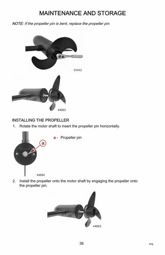
NOTE: If the propeller pin is bent, replace the propeller pin.
53442
44663
INSTALLING THE PROPELLER1. Rotate the motor shaft to insert the propeller pin horizontally.
a - Propeller pin
2. Install the propeller onto the motor shaft by engaging the propeller ontothe propeller pin.
44663
a
44664
MAINTENANCE AND STORAGE
36 eng

3. Install the washer (or anode, for saltwater models) onto the propeller shaftthen install the propeller nut. Tighten the propeller nut securely.
53442
4. Tighten the propeller nut another ¼ turn.
MAINTENANCE AND STORAGE
eng 37

TroubleshootingNOTE: For service information, contact any certified MotorGuide servicecenter. For a full listing of MotorGuide service centers, go towww.motorguide.com or contact any Mercury Marine service office.
Symptom Possible Cause Resolution
Trolling motor doesnot respond towireless commands
Weak trollingmotor batteries
Check the battery chargeindicator on the trolling motor.Recharge or replace batteries asrequired.
Weak handheldremote battery orweak foot pedalbattery
Replace the handheld remotebattery (one AAA‑size) or footpedal batteries (two AA‑size).
Wirelesscontrollers notsynced
Refer to Activating the WirelessFoot Pedal or Activating theHandheld Remote.
Loss of power
Weak trollingmotor batteries
Check the battery chargeindicator on the trolling motor.Recharge or replace the batteriesas required.
Loose or corrodedbatteryconnections
Inspect battery connections forcleanliness and tightness.
Propeller is loose,damaged, oroff‑balance
Refer to Propeller Replacement.
Wiring or electricalconnection faulty
Wire gauge from the battery tothe trolling motor is insufficient.6‑gauge wire is recommended.
Magnets crackedor chipped
The motor will whine or grind.Contact a Service Center.
Water intrusion inthe lower unit Contact a Service Center.
OWNER SERVICE ASSISTANCE
38 eng
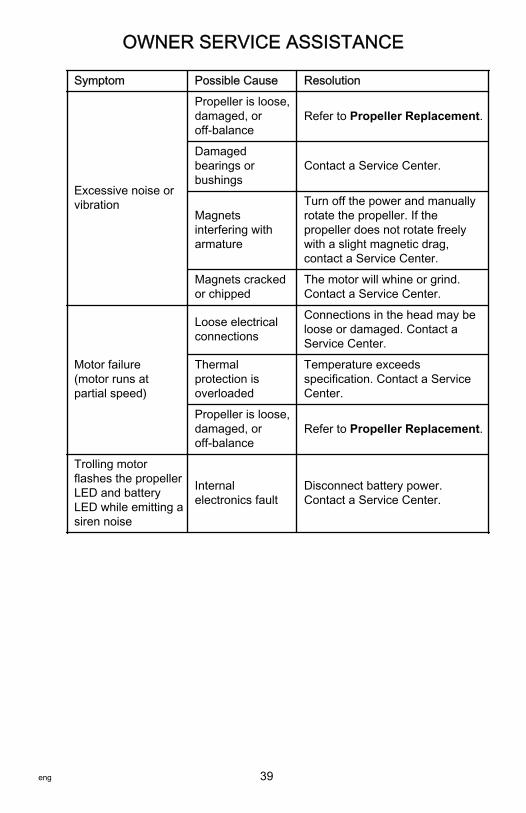
Symptom Possible Cause Resolution
Excessive noise orvibration
Propeller is loose,damaged, oroff‑balance
Refer to Propeller Replacement.
Damagedbearings orbushings
Contact a Service Center.
Magnetsinterfering witharmature
Turn off the power and manuallyrotate the propeller. If thepropeller does not rotate freelywith a slight magnetic drag,contact a Service Center.
Magnets crackedor chipped
The motor will whine or grind.Contact a Service Center.
Motor failure(motor runs atpartial speed)
Loose electricalconnections
Connections in the head may beloose or damaged. Contact aService Center.
Thermalprotection isoverloaded
Temperature exceedsspecification. Contact a ServiceCenter.
Propeller is loose,damaged, oroff‑balance
Refer to Propeller Replacement.
Trolling motorflashes the propellerLED and batteryLED while emitting asiren noise
Internalelectronics fault
Disconnect battery power.Contact a Service Center.
OWNER SERVICE ASSISTANCE
eng 39
Symptom Possible Cause Resolution
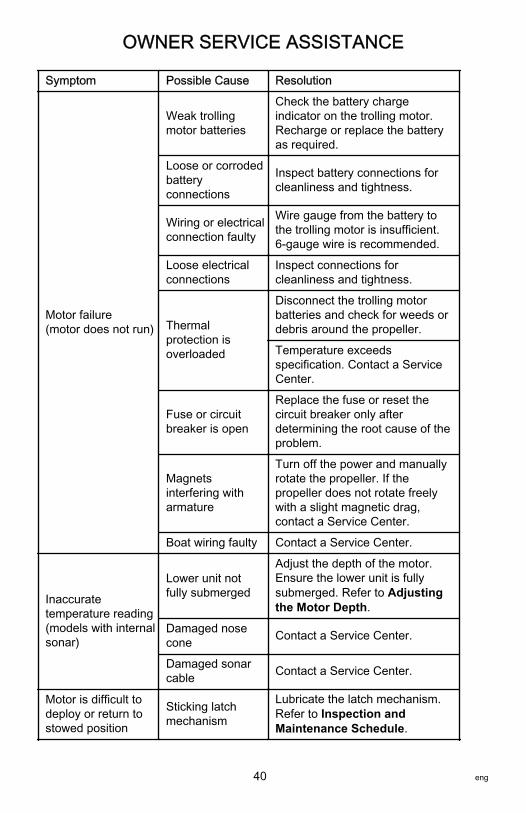
Motor failure(motor does not run)
Weak trollingmotor batteries
Check the battery chargeindicator on the trolling motor.Recharge or replace the batteryas required.
Loose or corrodedbatteryconnections
Inspect battery connections forcleanliness and tightness.
Wiring or electricalconnection faulty
Wire gauge from the battery tothe trolling motor is insufficient.6‑gauge wire is recommended.
Loose electricalconnections
Inspect connections forcleanliness and tightness.
Thermalprotection isoverloaded
Disconnect the trolling motorbatteries and check for weeds ordebris around the propeller.
Temperature exceedsspecification. Contact a ServiceCenter.
Fuse or circuitbreaker is open
Replace the fuse or reset thecircuit breaker only afterdetermining the root cause of theproblem.
Magnetsinterfering witharmature
Turn off the power and manuallyrotate the propeller. If thepropeller does not rotate freelywith a slight magnetic drag,contact a Service Center.
Boat wiring faulty Contact a Service Center.
Inaccuratetemperature reading(models with internalsonar)
Lower unit notfully submerged
Adjust the depth of the motor.Ensure the lower unit is fullysubmerged. Refer to Adjustingthe Motor Depth.
Damaged nosecone Contact a Service Center.
Damaged sonarcable Contact a Service Center.
Motor is difficult todeploy or return tostowed position
Sticking latchmechanism
Lubricate the latch mechanism.Refer to Inspection andMaintenance Schedule.
OWNER SERVICE ASSISTANCE
40 eng

Symptom Possible Cause Resolution
Difficulty removingpropeller
Bent propeller pin
Hold one blade and lightly tap theopposite blade with a rubbermallet.
Use a putty knife on both sides ofthe propeller to apply equalpressure.
Bent armatureshaft Contact a Service Center.
Troubleshooting the Foot Pedal and Handheld RemoteERASING THE RECEIVER'S MEMORYErasing the receiver's memory will erase all electronic ID numbers that arestored in the receiver's memory.1. Plug in the battery cable to a power source. In less than ten seconds,
press the left arrow, right arrow, +, and – buttons on the handheldremote simultaneously.
2. Listen for a long beep indicating the receiver has erased all storedelectronic ID numbers.
NOTE: If all four buttons on the remote are not pressed simultaneously withinten seconds, or a long beep is not heard, unplug the battery cables from thepower source and then refer to Activating the Wireless Foot Pedal andActivating the Handheld Remote in the Product Installation, Wiring, andBattery Information section of this manual.
REPROGRAMMING THE WIRELESS FOOT PEDAL OR REMOTENOTE: This activation procedure applies to the foot pedal and handheldremote.IMPORTANT: To activate multiple foot pedals or remotes, the motor must beunplugged from the power source and then plugged back into the power sourcebetween activating each control device.1. Unplug the battery cables from the power source. Wait 30 seconds and
then plug the motor into the power source.2. In less than ten seconds, press and hold the left arrow and right arrow
buttons on the handheld remote. For the foot pedal controller, hold thepropeller and anchor button simultaneously.
FOOT PEDAL BATTERY REPLACEMENTBattery required: Two AA alkaline batteries
OWNER SERVICE ASSISTANCE
eng 41

1. Remove the two screws securing the battery cover plate. Remove thebattery cover plate.
a - Battery cover plateb - Screws
2. Remove the batteries from the battery holder.3. Install the new batteries in the proper orientation for correct polarity.4. Ensure the rubber seal is positioned correctly around the battery cover
plate.
a - AA alkaline batteriesb - Rubber seal
ab
a
51760
51761
a
b
OWNER SERVICE ASSISTANCE
42 eng
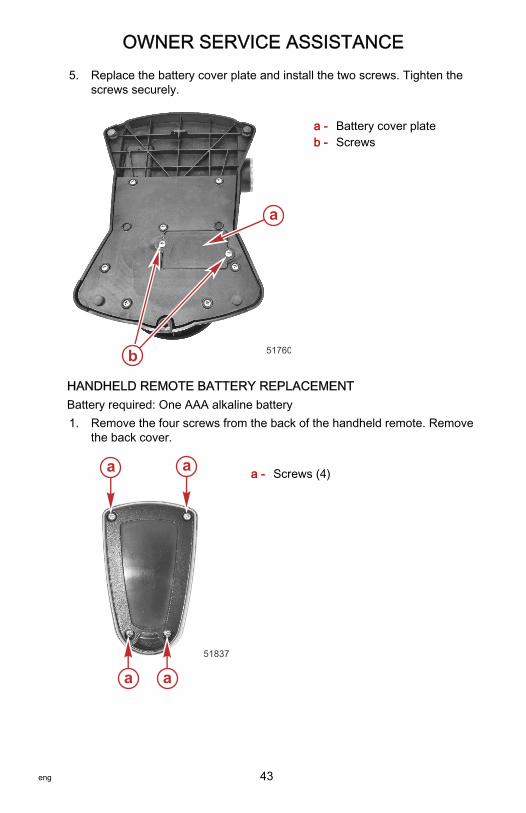
5. Replace the battery cover plate and install the two screws. Tighten thescrews securely.
a - Battery cover plateb - Screws
HANDHELD REMOTE BATTERY REPLACEMENTBattery required: One AAA alkaline battery1. Remove the four screws from the back of the handheld remote. Remove
the back cover.
a - Screws (4)
ab
a
51760
a a
a a51837
OWNER SERVICE ASSISTANCE
eng 43

2. Remove the old battery from the battery holder.
51838
3. Insert the new battery with the positive (+) side facing the positive (+) endof the battery holder.
4. Replace the handheld remote back plate and install the four screws.Ensure that the rubber seal is positioned correctly between the two halvesof the handheld remote. Tighten the screws securely.
a - Negative (–) end of battery holderb - Batteryc - Positive (+) end of battery holderd - Rubber seal
Service AssistanceYour satisfaction with your product is very important to us. If you have aproblem or question about your motor, contact your dealer or any certifiedMotorGuide Service Center. For more service assistance information, refer toWarranty Information.The following information will be needed by the service office:
a
b
c
d51839
OWNER SERVICE ASSISTANCE
44 eng

• Your name and address• Daytime telephone number• Model and serial number of your trolling motor• Proof of purchase or registration verification• Nature of problem
Mercury Marine Service OfficesFor assistance, call, fax, or write. Please include your daytime telephonenumber with mail and fax correspondence.
United States, Canada
Telephone English +1 920 929 5040Français + 905 636 4751
Mercury MarineW6250 Pioneer RoadP.O. Box 1939Fond du Lac, WI 54936-1939Fax English +1 920 929 5893
Français +1 905 636 1704
Website www.mercurymarine.com
Australia, Pacific
Telephone +61 3 9791 5822 Brunswick Asia Pacific Group41–71 Bessemer DriveDandenong South, Victoria 3175Australia
Fax +61 3 9706 7228
Europe, Middle East, Africa
Telephone +32 87 32 32 11 Brunswick Marine EuropeParc Industriel de Petit-RechainB-4800 Verviers,Belgium
Fax +32 87 31 19 65
Mexico, Central America, South America, Caribbean
Telephone +1 954 744 3500 Mercury Marine11650 Interchange Circle NorthMiramar, FL 33025U.S.A.
Fax +1 954 744 3535
Asia, Singapore, Japan
Telephone +65 65466160 Brunswick Asia Pacific GroupT/A Mercury Marine Singapore Pte Ltd29 Loyang DriveSingapore, 508944
Fax +65 65467789
OWNER SERVICE ASSISTANCE
eng 45