xlr8 user manual fpga development board - … value of the pinb and pind registers is therefore 0x3f...
TRANSCRIPT
Copyright 2018 Alorium Technology
FPGA
DEVELOPMENT BOARD Part Number: XLR8R22M08V5U0DI
XLR8 User Manual
February 14, 2018

Copyright 2018 Alorium Technology Page 2
Version DATE AUTHOR CHANGES1.0 April3,2016 mwebber InitialVersion
1.1 Dec14,2016 jpeterson AddedBestPracticessectionforSPI1.2 Feb1,2017 hjuedes Updated3.3ReconfigurabilityInstructions1.3 Feb8,2017 hjuedes UpdatedRegisterSummarydescription1.4 Apr11,2017 hjuedes Updatedboardschematics1.5 Feb14,2018 Hjuedes UpdatedRegisterSummaryandSchematics

Copyright 2018 Alorium Technology Page 3
Table of Contents
1 Overview................................................................................................................................................42 Usage.......................................................................................................................................................4
3 DifferencesbetweenXLR8andArduinoUno/SparkfunRedBoard.......................................43.1 USB..................................................................................................................................................................43.2 XceleratorBlocks(XBs)............................................................................................................................53.3 Reconfigurability........................................................................................................................................53.3.1 ConnectingtoGround..........................................................................................................................................................5
3.4 I/O...................................................................................................................................................................63.5 ADC.................................................................................................................................................................73.6 BootloaderandICSPheader....................................................................................................................73.7 I2C/TwoWireInterface(TWI)..............................................................................................................83.8 UART...............................................................................................................................................................83.9 SPI...................................................................................................................................................................83.9.1 SPIBestPractices...................................................................................................................................................................8
3.10 AnalogCompare..........................................................................................................................................93.11 EEPROM......................................................................................................................................................103.12 Power..........................................................................................................................................................103.13 Pin13LED...................................................................................................................................................103.14 JTAGInterface...........................................................................................................................................10
4 ATmega328pfeaturesnotimplemented....................................................................................104.1 Fuses............................................................................................................................................................114.2 PowerReduction......................................................................................................................................11
5 XceleratorBlocks(XBs)...................................................................................................................115.1 FloatingPoint............................................................................................................................................125.2 ServoControl............................................................................................................................................125.3 NeoPixelControl......................................................................................................................................12
6 RegisterSummary.............................................................................................................................136.1 XLR8andXBRegisterDescriptions....................................................................................................186.1.1 XLR8VERL,XLR8VERH,XLR8VERT–VersionNumberRegisters.................................................................186.1.2 FCFGCID–ChipIDRegister.............................................................................................................................................186.1.3 CLKSPD–ClockSpeedRegister.....................................................................................................................................186.1.4 XICR,XIFR,XMSK-XLR8IRQRegisters.....................................................................................................................196.1.5 OX8ICR,OX8IFR,OX8MSK-OpenXLR8PinChangeInterrupts......................................................................196.1.6 FCFGDAT,FCFGSTS,FCFGCTL–FPGAReconfigurationRegisters...............................................................206.1.7 SVPWH,SVPWL,SVCR–ServoXBRegisters...........................................................................................................206.1.8 NEOD2,NEOD1,NEOD0,NEOCR–NeoPixelXBRegisters................................................................................216.1.9 XFCTRL,XFSTAT,XFR0,XFR1,XFR2,XFR3–FloatingPointXBRegisters................................................226.1.10 XLR8ADCR–XLR8ADCControlRegister............................................................................................................226.1.11 XLR8PID – XLR8 PID......................................................................................................................................................226.1.12 XLR8Quad – XLR8 Quadrature..............................................................................................................................23
7 SchematicsandLayout.....................................................................................................................248 Credits...................................................................................................................................................26

Copyright 2018 Alorium Technology Page 4
1 Overview XLR8isanFPGA-basedapplicationacceleratoranddevelopmentboardthathasbeenspecificallydesignedtolook,feel,andactlikeastandardArduino.ItisprogrammedwiththepopularandeasytouseArduinoIDE.TheheartofXLR8isanFPGAchipthatisconfiguredwithanATMega328microcontrollercloneaswellasadditionalacceleratorfunctions.XLR8providesanoptionforArduinodeveloperstoachievesignificantlyimprovedperformanceinthesamephysicalfootprintandusingthesametoolchainasstandardArduinoUnoandothersimilarArduinocompatibleboards,evenwhenincorporatingcustomhardwarefunctionsviaacceleratorblocks.
2 Usage XLR8canbeprogrammedwithArduinosketchesfromtheArduinoIDEbyselecting“ArduinoUno”asthetargetboard,inthesamewayastheUno.ThepinheadersarecompliantwiththeArduinoUnoR3layout.Ithasthesameanalogpins,thesamedigitalpins,andthesamepinswithPWMfunctionalityastheUno.So,usingitasacloneoftheUnoisasimpleasusinganUno.TherealfunstartsafterinstallingourArduinoBoardpackageasdescribedintheinstructionsathttps://github.com/AloriumTechnology/Arduino_Boards,enablingadvancedfeaturessuchasdoublingthemicrocontroller’sclockspeedorutilizingXceleratorBlocks(XBs).Butyoudon’tneedtodothatuntilyouareready.
3 Differences between XLR8 and Arduino Uno/Sparkfun RedBoard
3.1 USB SimilartotheSparkfunRedBoard,XLR8usesaUSBmini-BconnectorandanFTDIchiptodotheUSB-to-Serialconversion,whichisslightlydifferentthantheUno.Ifyouhaven’talready,you’lllikelyneedtoinstallFTDIdrivers.NotethatthisisnotneededandshouldnotbedoneifyouareusingMacOSElCapitanorlater.TheOSwillhavethecorrectdrivers.Sparkfunhasagreattutorialshowingjusthowtodothathttps://learn.sparkfun.com/tutorials/how-to-install-ftdi-drivers).WehavenoticedfortheMacthatSparkfun’stutorialdoesn’tmentionrestartingyourcomputerafterinstallingthedriver,butwe’vegenerallyneededtodothatandeverythinghasworkedgreatafterwards.WehavealsonoticedthattheFTDIdriverinolderLinuxkernels(specifically,version2.6orolder)doesnotappeartosupportthenewerFTDIchipsthatareusedonXLR8,Sparkfun’sRedBoard,andmanyotherproducts.ThiscanbefixedbyupgradingyourLinuxkerneltoversion3.10ornewer.

Copyright 2018 Alorium Technology Page 5
3.2 Xcelerator Blocks (XBs) XceleratorBlocksgiveXLR8aperformanceadvantagethroughacombinationofcustomhardwareintheFPGAfabricalongwithasoftwarelibrarythatisabletocommunicatewiththathardwareandmakeiteasyforuserstotakeadvantageoftheperformance.Thesoftwarelibrariesareavailableonourgithubsite(https://github.com/AloriumTechnology),butitiseasytoinstallthemwithoutevengoingtogithub.IntheArduinoIDE,gotothemenuSketch->IncludeLibrary->ManageLibraries,whichwillopentheLibraryManagerinanewwindow.EnterXLR8inthesearchbarandyouwillfindtheentriesforthevariousXLR8librariesavailable.ClickonthedesiredlibraryandanInstallbuttonwillappearforit.
3.3 Reconfigurability OneofthemostawesomethingsaboutXLR8isitsre-configurability.XLR8isabletoholdtwodifferentFPGAimages.Image1canbereconfiguredfromtheArduinoIDEtotakeadvantageofincreasedfunctionalityasnewXBsareintroduced.ThereconfigurationfilesareobtainedbyinstallingourArduinoBoardpackageasdescribedintheinstructionsathttps://github.com/AloriumTechnology/Arduino_Boards.Image0isneverchangedandistypicallyunusedunlesstheprimaryimage1becomescorrupted.Ifnecessary,a“factoryreset”ofXLR8canbeperformedbygroundingtheFPGAsideofR51(cfg_sel)whileapplyingpowertotheboard.Itonlytakesamomentarygroundingtocausethistohappen.Thefactoryimageisthenloaded.Anylossofpowertotheboardwillstillcausethecorruptedimagetobereloaded,however.Typically,theuserwillwanttoreburnaknown-goodimageintoimage1beforeproceeding.
3.3.1 Connecting to Ground

Copyright 2018 Alorium Technology Page 6
3.4 I/O TheFPGAattheheartofXLR8isa3.3vdevice.However,unlikeother3.3vboards,we’vemadeaconcertedefforttomakeXLR8ascompatibleaspossiblewiththe5vArduinoUno.We’vedonethisbyaddinglevelshiftingandprotectioncircuitrytotheI/Osothatexistingshieldscanbeusedwithoutfearofdamagingtheboard.ThedigitalI/O’s(RX,TX,andD2-D13)canbothdriveandreceive5Vsignalsprovidinggreatcompatibilitywithallshields.TheanalogI/O’s(A0-A5)cantoleratebothanaloganddigitalinputsupto5.0V,andasdigitaloutputscandriveupto3.3Vandthatshouldworkfineforthemajorityofshieldsandothercircuits.XLR8provides5.0VontheIOREFpinfornewershieldsthatusethatfeature.WhileATmega328pinputscanenableordisabletheinternalweakpullupresistors,inXLR8,thepullupsdifferbypinasfollows:
• RX,TX,D2-D13:StrongpullupsonXLR8board(1Kohms)arealwaysenabled.TheinitialvalueofthePINBandPINDregistersistherefore0x3Fand0xFFrespectively.
• A0-A5:Nopullups• SDA,SCL:StrongpullupsonXLR8board(1Kohms)areincluded.WhenusingArduino
libraries,Wire.begin()enablesthepullupsfortheI2Ccase(assumingthePUDbitoftheMCUCR(0x35)registerisnotset)withoutanyadditionalworkrequiredfromtheuser.Ifdesired,disablingthepullupsinArduinoisassimpleasdoingboth

Copyright 2018 Alorium Technology Page 7
digitalWrite(SDA, LOW); anddigitalWrite(SCL, LOW);.OutsideoftheArduinoenvironmentthepullupsareenabledwhenPUDislow,TWENishigh,andbothPORTC4andPORTC5arehigh.
3.5 ADC TheADCusedinXLR8ishigherperforminginbothspeedandresolutionthantheADCfoundintheATMega328p.Bydefault,doingananalogReadwillgivethesamespeedand10bitresolutionasanArduinoUno.ByusingtheXLR8ADClibrary(https://github.com/AloriumTechnology/XLR8ADC)youcanget12bitresolution.Furtherenhancementswillbeavailableinthefuture.OneADCdifferencebetweenXLR8andArduinoUno/SparkfunRedBoardoccurswhenrunningfromUSBpower.TheUSBmaysupplyavoltagethatissomewhatlowerthan5VandbecausetheUnoandRedBoardusethisforthedefaultanalogreferenceitresultsinhigherADCreadingscomparedbothtowhatwouldbeexpectedandtowhatismeasuredwhenpoweredfromthebarrelconnector.TheXLR8boarddoesnotsufferfromthisissue;itwillgivethesameADCreadingwhetherpoweredfromthebarrelorfromUSB.Someshields,however,canbedeceiving.Ifananalogvoltagethattheshieldiscreatingdropsalongwiththe5VUSBpower,itwillappearontheUno/RedboardthattheADCreadingsstaysomewhatconstantwhileonXLR8theADCreadingswillbereduced.IfitisdesiredtohaveXLR8varythereferencevoltagewiththeUSBpowersimilartoanUno/Redboard,thiscanbeaccomplishedquiteeasilybywiringfromthe5VheaderpintotheAREFheaderpinandusingArduino’sanalogReference(EXTERNAL);.WhiletheATMega328pisabletoswitchitsADCreferencevoltagebetweeninternal5V,internal1.1V,andexternalreferences,XLR8usescircuitryontheboardtomakethisselection.Fromtheuser’spointofview,thereshouldn’tbeanoticeabledifference.ToensurethatXLR8cantolerateADCinputsupto5V,theanaloginputsrunthroughanop-ampandvoltagedividercircuitbeforeenteringtheFPGA.Again,fromtheuser’spointofview,thereshouldn’tbeanoticeable.WhiletheADCchannelselectionisthesameformeasuringtheprimarysixanaloginputs(ADMUX=0000through0101),therearedifferencesintheotherchannels.Channel6(ADMUX=0110)readsfromthevoltagedividercreatedbyR30andR59,andshouldbearoundthemaxADCvalue(1023whenin10bitmode)ifthe5Vsupplyisatorabove5.0V,butmaybeslightlylessifthe5Vsupplyislower.Channel7,andthetemperaturesensorarenotimplemented(ADMUX=0111and1000).UsingtheADCtoreadthebandgap(ADMUX=1110)doesnotactuallydoameasurementbutreturnsacalculatedvalueequivalentto1.1/Aref.UsingtheADCtoreadground(ADMUX=1111)doesnotactuallydoameasurementandinsteadreturnsafixedvalueof0.
3.6 Bootloader and ICSP header XLR8usestheOptibootbootloaderthatisusedbytheArduinoUno,withaslightmodificationthatallowsittoruncorrectlyatdifferentCPUspeeds.AsanextraindicationofXLR8’scurrentCPUspeed,youmaynoticewhenrunningat32MHzthatthebeginningofanuploadsequence
Copyright 2018 Alorium Technology Page 8
blinksthepin13LEDthreetimesratherquicklyjustlikeanArduinoUno,whileat16MHzyougettwoslightlyslowerblinks.Thisbootloaderishardcodedintothedesignandcannotbechangedbytheuser.Ifyouhaveaneedforsomethingdifferentinthebootloader,we’dbeinterestedtohearaboutit.ConsistentwithusingOptiboot,theBOOTRST“fuse”ishardcodedtozero(programmed)andtheIVSELandIVCEbitsoftheMCUCR(0x35)registerarehardcodedtozero.XLR8isprogrammedonlyviatheUSB-UARTpath.WhiletheXLR8boardincludestheICSPheaderitisusefulonlyasaconvenientconnectorfortheSPIinterface;itcan’tbeusedtoloadprograms/sketchesintothedesign.
3.7 I2C / Two Wire Interface (TWI) AlthoughtheArduinoUno’sRev3layouthasseparateSDAandSCLpinsforI2C/TWI,theyarestillconnectedontheUnoboardtotheoriginalA4/A5pins.ThismeansthatwhenusingtheI2Cinterface,twoofyouranaloginputsarenolongeravailable.OnXLR8,I2C/TWIisbydefaultonlyavailableontheSDA/SCLpinsandtheA4/A5pinscanstillbeusedasanalogordigitalinputs(butnotoutputs).IfyouhaveexistingprojectsthatneedtouseA4/A5astheI2Cpins,youcanreconnectthemtoSDA/SCLbypopulating0ohmresistorsatR60andR61.AnotherdifferencebetweentheI2C/TWIonXLR8andArduinothatyouwilllikelynevernoticeisrelatedtotheTWBRregister.WhileArduinoallowsrunningwithnon-standardSCLclockfrequencies,XLR8isoptimizedfor100KHzand400KHzoperationandsettingTWBRandtheprescalerbitsofTWSRforotherspeedswillnotbeoperational.
3.8 UART XLR8hasaUniversalAsynchronousserialReceiverandTransmitter(UART)blocksimilartotheATmega328pUSART.However,XLR8’sUARTdoesnotimplementtheSynchronousUART(USART)inSPIModesthatareavailableontheATmega328p.Therefore,theUMSEL01,UMSEL00,andUCPOL0bitsoftheUCSR0C(0x)register,whileimplemented,havenoeffectandtheUARTblockalwaysrunsin“AsynchronousUART”mode.WehavenotyetseenacasewhereanythingelseisneededinanArduinoenvironment;ifyouhaveone,pleaseletusknow.
3.9 SPI TheSPIinterfaceonXLR8shouldoperatethesameastheSPIinterfaceonanUnoorRedboard.Theonlyitemtonoteisthatwe’veseensomeSPIexampleswheretheXLR8/Uno/RedboardistheSPIslaveandinsteadofbeingdrivenfromtheSPImaster,theSSpinisleftfloating.Althoughasloppydesignpractice,anUnoorRedboardwilloftenstillworkinthisarrangement.OurXLR8board,duetoitsI/Opullups,needstohaveSSdrivenandnotfloating.
3.9.1 SPI Best Practices Inrarecases,wehaveobservedanissuewiththeSPIclockbeingproperlysampledbyashield.Wesuggestaddinga100-200ohmpulldownresistortotheSPIclockpinD13formorerobustoperation.

Copyright 2018 Alorium Technology Page 9
3.10 Analog Compare XLR8doesnothavetheAnalogComparefunctionthatisfoundintheATmega328p.TheACMEbitandanalogcomparetriggering(ADTS=001)oftheADCSRB(0x7B)register,theACSR(0x30)register,andtheDIDR1(0x7F)registerarenotimplemented.Ifananalogcomparefunctionisdesired,pins6and7onthe(unpopulated)JTAGconnectorarewiredtoMAX10pinsDIFFIO_TX_RX_B1P/NwhichisadifferentialI/O.UsingtheOpenXLR8platform,ausercouldimplementananalogcomparefunctionthatisverysimilartotheATMega328's,althoughthepinvoltagewouldneedtobelimitedto3.3V.

Copyright 2018 Alorium Technology Page 10
3.11 EEPROM XLR8doesnothavetheEEPROMmemorythatisfoundintheATmega328p.However,thereisanSOIC-8locationthatcouldbepopulatedwithanEEPROMandusingtheOpenXLR8platform,ausercouldimplementanEEPROMfunctionthatisverysimilartotheonefoundintheATMega328.TheSOIC-8pinoutis:
FPGApin TypicalUse
SOIC-8pin
SOIC-8pin
TypicalUse
FPGApin
C12 Addr0 1 1 + -
8 Vcc 3.3VB13 Addr1 2 7 WP D11C11 Addr2 3 6 SCL D12Gnd Vss 4 5 SDA E13
3.12 Power TheArduinoUnoandtheSparkfunRedBoardareonlyabletosupply50mAfromthe3.3Vpinheader.XLR8hasa1.5Aregulatorcreatingits3.3Vpower(anLT1963EST-3.3)andtheMax10FPGAisestimatedtodrawlessthan100mA,leavingasignificantamountof3.3Vpoweravailabletotheuserforshieldsorothercircuits.(KeepinmindthatUSBpowerislimitedtoabout500mA.)
3.13 Pin13 LED Digitalpin13isusedforboththeon-boardLEDaswellastheSPIclock,SCK.WhiletheArduinoUnoR3addscircuitrytopreventtheLEDanditspulldownresistorfromaffectingSCK,theSparkfunRedboarddoesnottakethoseprecautions.OnXLR8we’vedecidedtofollowArduino’sleadandkeepSCKseparatedfromtheLED.
3.14 JTAG Interface TheJTAGpinsontheboardareusedforMFGloadingoftheoriginalXLR8image,aswellasMFGtesting.AllavailableXLR8imagesandOpenXLR8imagesmustbeloadedthroughtheIDE.UsingtheJTAGpinstoloadtheMAX10FPGAwithanyotherimagewillwipeouttheXLR8imageandnotallowarecoverybacktothefactoryimage.IftheuserwouldliketoloadtheirownFPGAimages,theywillneed100-ohmpull-downresistorontheTCKpintodotheload.
4 ATmega328p features not implemented TheATmega328pmicrocontrollerincludesseveralfeaturesthatareseldomorneverusedinanArduinoenvironment.InXLR8,thesefeaturesarehardcodedtomatchtheArduinousage.Therefore,whencomparingtotheATmega328pspecificationthefollowingdifferencesmaybenoted,howevertheydonotimpactfunctionalityinanArduinoenvironment.OneexceptionisthatArduinoUnoallowsprogrammingviatheSPIinterfacewhile,asmentionedinsection3.6,XLR8hasnotimplementedthisfeature(SPIENfuse).

Copyright 2018 Alorium Technology Page 11
4.1 Fuses TheArduinoUnorunswiththefollowingfusesettings.
• LowFuse0xFF(allunprogrammed)o CKDIV8:Defaulttoclockdivisionfactorof1.o CKOUT:Don’toutputsystemclockonportBpin0o SUT1/0:Startuptimeo CKSEL3/2/1/0
§ Alwaysuseexternalclock(suppliedby16MHz)crystal.§ XLR8doesnothavetheinternal128kHzRCOscillatorortheCalibrated
InternalRCOscillatorthatexistsinATmega328p.TheOSCCAL(0x66)registerisnotimplemented.
§ BecauseATmega328sharestheTOSC1/2pinswiththeXTAL1/2pins,andXTAL1/2areusedtobringintheexternal16MHzclock,theasynchronousmodeoftimer/counter2isnotavailableandtheASSRregister(0xB6)isnotimplemented.
• HighFuse0xDEinArduino(SPIENandBOOTRSTprogrammed),0xFEinXLR8(BOOTRSTprogrammed)
o RSTDISBL:Externalresetisalwaysenabled.ThisishowthemicrocontrollerreturnstothebootloadertouploadanewsketchfromtheArduinoIDEtoprogrammemory
o DWEN:ThedebugwirefeatureisnotenabledinArduinoandisnotimplementedinXLR8.
o SPIEN:WhileArduinoprogramsthisbit,XLR8insteadfunctionsasifitwerenotprogrammed(seesection3.6)
o WDTON:Watchdogalwaysonnotenabledo EESAVE:EEPROMnotpreservedthroughchiperase.NotapplicableonXLR8.o BOOTSZ1/0:Bootloaderis256wordsstartingat0x3F00o BOOTRST:Resetstartsatthebootloaderaddress
• ExtendedFuse0x05inArduino(BODLEVEL1programmed),0x07inXLR8(allunprogrammed)
o BODLEVEL2/1/0:InXLR8thebrownoutdetectioncircuitryisdisabledandnotimplemented.TheBODSandBOSEbitsoftheMCUCR(0x35)registerarenotimplemented,aswellastheBORFbitoftheMCUSR(0x34)register.
4.2 Power Reduction Becausewedon’tseeitbeingusedveryoften(oratall)inArduinoprojects,XLR8hasnotimplementedtheATmega328p’sPowerReductionRegisterPRR(0x64),SleepModeControlRegisterSMCR(0x33),orClockPrescaleRegisterCLKPR(0x61).Theycouldbeaddedifcustomerfeedbackindicatesthatwouldbeagoodthingtodo.
5 Xcelerator Blocks (XBs) XceleratorBlocksarecustomhardwareblocksimplementedwithintheXLR8FPGAchipandaretightlyintegratedwiththeATmega328clonethatisalsoimplementedinsidetheFPGAchip.Thesecustomhardwareblockscanimplementalmostanyfunctionalityyoucandreamup,andcanthen

Copyright 2018 Alorium Technology Page 12
beloadedintotheXLR8aswiththeArduinotoolset.SinceanFPGAcanbereprogrammedmanytimes,asingleXLR8canbereconfiguredtoincorporatedifferentXBdependingontheprojectrequirements.XLR8shipswiththreesampleXBs:FloatingPoint,NeoPixel,andServoControl.Asmentionedinsection3.2,thesoftwarelibrariesaredeliveredas.zipfilesfromourgithubsite(https://github.com/AloriumTechnology).TheyareinstalledlikeotherArduino.ziplibrariesasdescribedhere(https://www.arduino.cc/en/Guide/Libraries-toc4).Note:ThereisonethingtobeawareofwithallArduinolibraries.Ifyoudownloadanupdatedversionandsimplyrenamethedirectoryoftheoldversion(perhapsyouthinkyoumightwanttogobacktoitormaybeyouarejustfeelingnostalgic),Arduinoverylikelywillstillendupusingtheoldversionasitsimplylooksforthefirstplaceitcanfindthe#includeheaderfilename,regardlessofwhatdirectoryitisin.Ifyouwanttosaveanoldversionofalibrary,moveittosomeplaceoutsideofyourArduino/librariesfolder.
5.1 Floating Point Asan8bitmicrocontroller,theATmega328pstruggleswithfloatingpointmath.TheFloatingPointXBprovidesfunctionsthatwillgiveyoufloatingpointresultsinabout¼thetimethatittakessoftwarefloatingpointtogetthesameanswer.Availablefunctionsincludeadd,subtract,multiply,anddivide.
5.2 Servo Control ItiscommonforthestandardServo.hlibrarytocausejitterintheservocontrolduetotiminguncertaintiescausedbyinterruptprocessing.TheServoControlXBcompletelyeliminatesthisjitterbyputtingadedicatedhardwaretimerbehindall20digitalandanalogpins.TheXLR8Servo.hlibraryisadrop-inreplacementforthestandardServo.hlibrary,sotakingadvantageofthisXBisassimpleaschangingonelineinyoursketchfrom#include <Servo.h>
to#include <XLR8Servo.h>
5.3 NeoPixel Control ThestandardArduinostrugglestomeetthetimingrequirementsofNeoPixels.WiththeXLR8NeoPixelhardwareandlibrary,interruptsremainenabled,datamemoryissaved,andpixelcolorinformationdoesnotneedtoberewrittenwhenbrightnessisloweredandthenbroughtbackup.TheXLR8NeoPixellibrarycanbeadrop-inreplacementforthestandardAdafruit_NeoPixellibrary.Itiscommonforotherlibraries,suchasAdafruit_NeoMatrix,tobuildontheAdafruit_NeoPixellibraryandwithjustthreelinesaddedtothetopofyoursketch,itispossibletogettheXLR8advantagesusedbythoselibrariesaswell.Forexample,
// 3 new lines added #include <XLR8NeoPixel.h> #define Adafruit_NeoPixel XLR8NeoPixel #define ADAFRUIT_NEOPIXEL_H // Existing lines kept #include <Adafruit_GFX.h>

Copyright 2018 Alorium Technology Page 13
#include <Adafruit_NeoMatrix.h> #include <Adafruit_NeoPixel.h>
Asexplanation,workingfromthebottomup:• IncludingAdafruit_NeoPixel.hremainsbecauseotherlibraryfilesthatweareusingbut
arenotmodifying(Adafruit_NeoMatrix.hinthiscase)have#include <Adafruit_NeoPixel.h>.ThewayArduinohandlescompilingandlinkinggenerallyrequiresthatlowerlevel#includesalsobeincludedinthesketch.
• IncludingAdafruit_NeoMatrixremainsbecausethatisthelibrarythatthisparticularsketchisusing
• IncludingAdafruit_GFXremainsforthesamereasonthatitwasthereinitially.ItisincludedbyAdafruit_NeoMatrix,andthewayArduinohandlescompilingandlinkinggenerallyrequiresthatlowerlevel#includesalsobeincludedinthesketch.
• EventhoughwearestillincludingtheAdafruit_NeoPixel.h,adding#define ADAFRUIT_NEOPIXEL_HcausesthatheaderfiletoappearemptyinsteadofhavingtheactualAdafruitlibrarycode.
• Byadding#define Adafruit_NeoPixel XLR8NeoPixel,anyplaceinyoursketch,orinthelibrariesthatyoursketchisusing,whereanAdafruit_NeoPixelstringisinstantiated,itwillinstantiateanXLR8NeoPixelstringinstead.
• Andofcourse,theXLR8NeoPixellibraryisincluded.
Easy.Powerful.Fun.Anddesignedtobecomeevenmorepowerfulinthefuture.Watchforupdates.
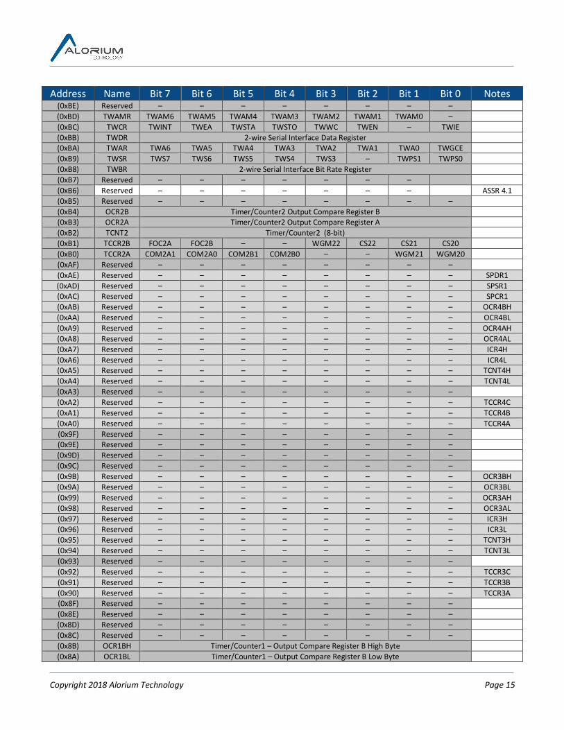
6 Register Summary TheregistersusedinXLR8arelistedbelow.ThosewithagreybackgroundhaveidenticalfunctiontotheequivalentATmega328pregister.ThosewithjustatouchofgreyarereservedinbothXLR8andATmega328pbutarenotedbecausetheyareusedintheATmega328pb.ThosewithgreenbackgroundfunctionliketheequivalentATmega328pregister,butwithsomedifferencesasnoted.ThosewithbluebackgroundarenewregistersaddedforXLR8functions.ThosewithwhitebackgroundareATmega328pregistersthatdonotexistinXLR8.Address Name Bit 7 Bit 6 Bit 5 Bit 4 Bit 3 Bit 2 Bit 1 Bit 0 Notes
(0xFF) Reserved – – – – – – – – (0xFE) Reserved – – – – – – – – (0xFD) SVPWH – – – – Servo Pulse Width High Register 6.1.7 (0xFC) SVPWL Servo Pulse Width Low Register 6.1.7 (0xFB) SVCR SVEN SVDIS SVUP SVCHAN 6.1.7 (0xFA) NEOD2 NeoPixel Data 2 register, function depends on NEOCMD 6.1.8 (0xF9) NEOD1 NeoPixel Data 1 register, function depends on NEOCMD, often high half of pixel address/length 6.1.8 (0xF8) NEOD0 NeoPixel Data 0 register, function depends on NEOCMD, often low half of pixel address/length 6.1.8 (0xF7) NEOCR NEOPIN NEOCMD 6.1.8 (0xF6) PID_OP_L Low Byte output 6.1.11 (0xF5) PID_OP_H High Byte output 6.1.11 (0xF4) PID_PV_L Process variable low byte 6.1.11

Copyright 2018 Alorium Technology Page 14
Address Name Bit 7 Bit 6 Bit 5 Bit 4 Bit 3 Bit 2 Bit 1 Bit 0 Notes (0xF3) PID_PV_H Process variable high byte 6.1.11 (0xF2) PID_SP_L Set point low byte 6.1.11 (0xF1) PID_SP_H Set point high byte 6.1.11 (0xF0) PID_KP_L KP coefficient low byte 6.1.11 (0xEF) PID_KP_H KP coefficient high byte 6.1.11 (0xEE) PID_KI_L KI coefficient low byte 6.1.11 (0xED) PID_KI_H KI coefficient high byte 6.1.11 (0xEC) PID_KD_L KD coefficient low byte 6.1.11 (0xEB) PID_KD_H KD coefficient high byte 6.1.11 (0xEA) PIDCR PEDEN PIDDIS PIDUPD PIDCHAN 6.1.11 (0xE9) QERAT3 Upper 8 bits of quadrature rate data 6.1.12 (0xE8) QERAT2 Upper-middle 8 bits of quadrature rate data 6.1.12 (0xE7) QERAT1 Lower-middle 8 bits of quadrature rate data 6.1.12 (0xE6) QERAT0 Lower 8 bits of quadrature rate data 6.1.12 (0xE5) QECNT3 Upper 8 bits of quadrature count data 6.1.12 (0xE4) QECNT2 Upper-middle 8 bits of quadrature count data 6.1.12 (0xE3) QECNT1 Lower-middle 8 bits of quadrature count data 6.1.12 (0xE2) QECNT0 Lower 8 bits of quadrature count data 6.1.12 (0xE1) Reserved – – – – – – – – (0xE0) QECR QEEN QEDIS QECLR QERATE QECHAN 6.1.12 (0xDF) Reserved – – – – – – – – (0xDE) Reserved – – – – – – – – (0xDD) Reserved – – – – – – – – TWAMR1 (0xDC) Reserved – – – – – – – – TWCR1 (0xDB) Reserved – – – – – – – – TWDR1 (0xDA) Reserved – – – – – – – – TWAR1 (0xD9) Reserved – – – – – – – – TWSR! (0xD8) Reserved – – – – – – – – TWBR1 (0xD7) Reserved – – – – – – – – (0xD6) XLR8VERT XLR8 Version Number Flags 6.1.1 (0xD5) XLR8VERH XLR8 Version Number Register High Byte 6.1.1 (0xD4) XLR8VERL XLR8 Version Number Register Low Byte 6.1.1 (0xD3) Reserved – – – – – – – – (0xD2) FCFGDAT FPGA Reconfiguration Data Register 6.1.6 (0xD1) FCFGSTS FCFGDN 0 FCFGFM FCFGRDY – – – – 6.1.6 (0xD0) FCFGCTL – FCFGSEC – FCFGCMD FCFGEN 6.1.6 (0xCF) FCFGCID Chip ID register 6.1.2 (0xCE) Reserved – – – – – – – – UDR1 (0xCD) Reserved – – – – – – – – UBBR1H (0xCC) Reserved – – – – – – – – UBBR1L (0xCB) Reserved – – – – – – – – UCSR1D (0xCA) Reserved – – – – – – – – UCSR1C (0xC9) Reserved – – – – – – – – UCSR1B (0xC8) Reserved – – – – – – – – UCSR1A (0xC7) Reserved – – – – – – – – (0xC6) UDR0 USART I/O Data Register (0xC5) UBRR0H – – – – USART Baud Rate Register High (0xC4) UBRR0L USART Baud Rate Register Low (0xC3) Reserved – – – – – – – – UCSR0D
(0xC2) UCSR0C UMSEL01 UMSEL00 UPM01 UPM00 USBS0 UCSZ01/ UDORD0
UCSZ00/ UCPHA0 UCPOL0 3.8
(0xC1) UCSR0B RXCIE0 TXCIE0 UDRIE0 RXEN0 TXEN0 UCSZ02 RXB80 TXB80 (0xC0) UCSR0A RXC0 TXC0 UDRE0 FE0 DOR0 UPE0 U2X0 MPCM0 (0xBF) Reserved – – – – – – – –
Copyright 2018 Alorium Technology Page 15
Address Name Bit 7 Bit 6 Bit 5 Bit 4 Bit 3 Bit 2 Bit 1 Bit 0 Notes (0xBE) Reserved – – – – – – – – (0xBD) TWAMR TWAM6 TWAM5 TWAM4 TWAM3 TWAM2 TWAM1 TWAM0 – (0xBC) TWCR TWINT TWEA TWSTA TWSTO TWWC TWEN – TWIE (0xBB) TWDR 2-wire Serial Interface Data Register (0xBA) TWAR TWA6 TWA5 TWA4 TWA3 TWA2 TWA1 TWA0 TWGCE (0xB9) TWSR TWS7 TWS6 TWS5 TWS4 TWS3 – TWPS1 TWPS0 (0xB8) TWBR 2-wire Serial Interface Bit Rate Register (0xB7) Reserved – – – – – – – (0xB6) Reserved – – – – – – – ASSR 4.1 (0xB5) Reserved – – – – – – – – (0xB4) OCR2B Timer/Counter2 Output Compare Register B (0xB3) OCR2A Timer/Counter2 Output Compare Register A (0xB2) TCNT2 Timer/Counter2 (8-bit) (0xB1) TCCR2B FOC2A FOC2B – – WGM22 CS22 CS21 CS20 (0xB0) TCCR2A COM2A1 COM2A0 COM2B1 COM2B0 – – WGM21 WGM20 (0xAF) Reserved – – – – – – – – (0xAE) Reserved – – – – – – – – SPDR1 (0xAD) Reserved – – – – – – – – SPSR1 (0xAC) Reserved – – – – – – – – SPCR1 (0xAB) Reserved – – – – – – – – OCR4BH (0xAA) Reserved – – – – – – – – OCR4BL (0xA9) Reserved – – – – – – – – OCR4AH (0xA8) Reserved – – – – – – – – OCR4AL (0xA7) Reserved – – – – – – – – ICR4H (0xA6) Reserved – – – – – – – – ICR4L (0xA5) Reserved – – – – – – – – TCNT4H (0xA4) Reserved – – – – – – – – TCNT4L (0xA3) Reserved – – – – – – – – (0xA2) Reserved – – – – – – – – TCCR4C (0xA1) Reserved – – – – – – – – TCCR4B (0xA0) Reserved – – – – – – – – TCCR4A (0x9F) Reserved – – – – – – – – (0x9E) Reserved – – – – – – – – (0x9D) Reserved – – – – – – – – (0x9C) Reserved – – – – – – – – (0x9B) Reserved – – – – – – – – OCR3BH (0x9A) Reserved – – – – – – – – OCR3BL (0x99) Reserved – – – – – – – – OCR3AH (0x98) Reserved – – – – – – – – OCR3AL (0x97) Reserved – – – – – – – – ICR3H (0x96) Reserved – – – – – – – – ICR3L (0x95) Reserved – – – – – – – – TCNT3H (0x94) Reserved – – – – – – – – TCNT3L (0x93) Reserved – – – – – – – – (0x92) Reserved – – – – – – – – TCCR3C (0x91) Reserved – – – – – – – – TCCR3B (0x90) Reserved – – – – – – – – TCCR3A (0x8F) Reserved – – – – – – – – (0x8E) Reserved – – – – – – – – (0x8D) Reserved – – – – – – – – (0x8C) Reserved – – – – – – – – (0x8B) OCR1BH Timer/Counter1 – Output Compare Register B High Byte (0x8A) OCR1BL Timer/Counter1 – Output Compare Register B Low Byte

Copyright 2018 Alorium Technology Page 16
Address Name Bit 7 Bit 6 Bit 5 Bit 4 Bit 3 Bit 2 Bit 1 Bit 0 Notes (0x89) OCR1AH Timer/Counter1 – Output Compare Register A High Byte (0x88) OCR1AL Timer/Counter1 – Output Compare Register A Low Byte (0x87) ICR1H Timer/Counter1 – Input Capture Register High Byte (0x86) ICR1L Timer/Counter1 – Input Capture Register Low Byte (0x85) TCNT1H Timer/Counter1 – Counter Register High Byte (0x84) TCNT1L Timer/Counter1 – Counter Register Low Byte (0x83) Reserved – – – – – – – – (0x82) TCCR1C FOC1A FOC1B – – – – – – (0x81) TCCR1B ICNC1 ICES1 – WGM13 WGM12 CS12 CS11 CS10 (0x80) TCCR1A COM1A1 COM1A0 COM1B1 COM1B0 – – WGM11 WGM10 (0x7F) Reserved – – – – – – – – DIDR1 3.9 (0x7E) DIDR0 – – ADC5D ADC4D ADC3D ADC2D ADC1D ADC0D (0x7D) XLR8ADCR AD12EN – – – – – – – 6.1.10 (0x7C) ADMUX REFS1 REFS0 ADLAR – MUX3 MUX2 MUX1 MUX0 3.5 (0x7B) ADCSRB – - – – – ADTS2 ADTS1 ADTS0 ACME 3.9 (0x7A) ADCSRA ADEN ADSC ADATE ADIF ADIE ADPS2 ADPS1 ADPS0 (0x79) ADCH ADC Data Register High byte (0x78) ADCL ADC Data Register Low byte (0x77) Reserved – – – – – – – – (0x76) Reserved – – – – – – – – (0x75) Reserved – – – – – – – – (0x74) Reserved – – – – – – – – (0x73) Reserved – – – – – – – – PCMSK3 (0x72) Reserved – – – – – – – – TIMSK4 (0x71) Reserved – – – – – – – – TIMSK3 (0x70) TIMSK2 – – – – – OCIE2B OCIE2A TOIE2 (0x6F) TIMSK1 – – ICIE1 – – OCIE1B OCIE1A TOIE1 (0x6E) TIMSK0 – – – – – OCIE0B OCIE0A TOIE0 (0x6D) PCMSK2 PCINT23 PCINT22 PCINT21 PCINT20 PCINT19 PCINT18 PCINT17 PCINT16 (0x6C) PCMSK1 – PCINT14 PCINT13 PCINT12 PCINT11 PCINT10 PCINT9 PCINT8 (0x6B) PCMSK0 PCINT7 PCINT6 PCINT5 PCINT4 PCINT3 PCINT2 PCINT1 PCINT0 (0x6A) OX8MSK OpenXLR8 Pin Control Interrupt Mask 6.1.4 (0x69) EICRA – – – – ISC11 ISC10 ISC01 ISC00 (0x68) PCICR – – – – – PCIE2 PCIE1 PCIE0 (0x67) OX8IFR OpenXLR8 Pin Control Interrupt Flag Register 6.1.4 (0x66) OX8ICR OpenXLR8 Pin Control Interrupt Register 6.1.4 (0x65) XACK XLR8 IRQ Acknowledge Register 6.1.4 (0x64) PRR – – – PRINTOSC – – – – 4.2, 6.1.3 (0x63) XMSK XLR8 IRQ Mask Register 6.1.4 (0x62) XIFR XLR8 IRQ Flag Register 6.1.4 (0x61) XICR XLR8 IRQ Control Register 6.1.4 (0x60) WDTCSR WDIF WDIE WDP3 WDCE WDE WDP2 WDP1 WDP0
0x3F(0x5F) SREG I T H S V N Z C 0x3E(0x5E) SPH – – – – SP11 SP10 SP9 SP8 0x3D(0x5D) SPL SP7 SP6 SP5 SP4 SP3 SP2 SP1 SP0 0x3C(0x5C) Reserved – – – – – – – – 0x3B(0x5B) XFR3 XLR8 Function (floating point) 32 bit Result High Byte 6.1.9 0x3A(0x5A) XFR2 XLR8 Function (floating point) 32 bit Result Byte 6.1.9 0x39(0x59) XFR1 XLR8 Function (floating point) 32 bit Result Byte 6.1.9 0x38(0x58) XFR0 XLR8 Function (floating point) 32 bit Result Low Byte 6.1.9 0x37(0x57) SPMCSR SPMIE RWWSB SIGRD RWWSRE BLBSET PGWRT PGERS SPMEN 0x36(0x56) Reserved – – – – – – – –

Copyright 2018 Alorium Technology Page 17
Address Name Bit 7 Bit 6 Bit 5 Bit 4 Bit 3 Bit 2 Bit 1 Bit 0 Notes
0x35(0x55) Reserved – – – – – – – – MCUCR
4.1,3.4,3.6 0x34(0x54) MCUSR – – – – WDRF – EXTRF PORF BORF 4.1 0x33(0x53) Reserved – – – – – – – – SMCR 4.2 0x32(0x52) Reserved – – – – – – – – 0x31(0x51) Reserved – – – – – – – – DWDR 0x30(0x50) Reserved – – – – – – – – ACSR 3.9 0x2F(0x4F) Reserved – – – – – – – – ACSRB 0x2E(0x4E) SPDR SPI Data Register 0x2D(0x4D) SPSR SPIF WCOL – – – – – SPI2X 0x2C(0x4C) SPCR SPIE SPE DORD MSTR CPOL CPHA SPR1 SPR0 0x2B(0x4B) GPIOR2 General Purpose I/O Register 2 0x2A(0x4A) GPIOR1 General Purpose I/O Register 1 0x29(0x49) CLKSPD Clock speed programming used by XLR8 bootloader 6.1.3 0x28(0x48) OCR0B Timer/Counter0 Output Compare Register B 0x27(0x47) OCR0A Timer/Counter0 Output Compare Register A 0x26(0x46) TCNT0 Timer/Counter0 (8-bit) 0x25(0x45) TCCR0B FOC0A FOC0B – – WGM02 CS02 CS01 CS00 0x24(0x44) TCCR0A COM0A1 COM0A0 COM0B1 COM0B0 – – WGM01 WGM00 0x23(0x43) GTCCR TSM – – – – – PSRASY PSRSYNC 0x22(0x42) EEARH EEPROM Address Register High Byte EEPROM
function could be
added - 3.11
0x21(0x41) EEARL EEPROM Address Register Low Byte 0x20(0x40) EEDR EEPROM Data Register 0x1F(0x3F) EECR – – EEPM1 EEPM0 EERIE EEMPE EEPE EERE 0x1E(0x3E) GPIOR0 General Purpose I/O Register 0 0x1D(0x3D) EIMSK – – – – – – INT1 INT0 0x1C(0x3C) EIFR – – – – – – INTF1 INTF0 0x1B(0x3B) PCIFR – – – – – PCIF2 PCIF1 PCIF0 0x1A(0x3A) Reserved – – – – – – – – 0x19(0x39) Reserved – – – – – – – – TIFR4 0x18(0x38) Reserved – – – – – – – – TIFR3 0x17(0x37) TIFR2 – – – – – OCF2B OCF2A TOV2 0x16(0x36) TIFR1 – – ICF1 – – OCF1B OCF1A TOV1 0x15(0x35) TIFR0 – – – – – OCF0B OCF0A TOV0 0x14(0x34) Reserved – – – – – – – – 0x13(0x33) Reserved – – – – – – – – 0x12(0x32) Reserved – – – – – – – – 0x11(0x31) XFSTAT XFDONE XFERR – – – – – – 6.1.9 0x10(0x30) XFCTRL – XFSTART – – – XFCMD 6.1.9 0x0F(0x2F) Reserved – – – – – – – – 0x0E(0x2E) Reserved – – – – – – – – 328PB PORTE 0x0D(0x2D) Reserved – – – – – – – – 328PB DDRE 0x0C(0x2C) Reserved – – – – – – – – 328PB PINE 0x0B(0x2B) PORTD PORTD7 PORTD6 PORTD5 PORTD4 PORTD3 PORTD2 PORTD1 PORTD0 pullup 3.4 0x0A(0x2A) DDRD DDD7 DDD6 DDD5 DDD4 DDD3 DDD2 DDD1 DDD0 0x09(0x29) PIND PIND7 PIND6 PIND5 PIND4 PIND3 PIND2 PIND1 PIND0 reset 3.4 0x08(0x28) PORTC – PORTC6 PORTC5 PORTC4 PORTC3 PORTC2 PORTC1 PORTC0 pullup 3.4 0x07(0x27) DDRC – DDC6 DDC5 DDC4 DDC3 DDC2 DDC1 DDC0 0x06(0x26) PINC – PINC6 PINC5 PINC4 PINC3 PINC2 PINC1 PINC0 0x05(0x25) PORTB PORTB7 PORTB6 PORTB5 PORTB4 PORTB3 PORTB2 PORTB1 PORTB0 pullup 3.4 0x04(0x24) DDRB DDB7 DDB6 DDB5 DDB4 DDB3 DDB2 DDB1 DDB0 0x03(0x23) PINB PINB7 PINB6 PINB5 PINB4 PINB3 PINB2 PINB1 PINB0 reset 3.4 0x02(0x22) Reserved – – – – – – – –

Copyright 2018 Alorium Technology Page 18
Address Name Bit 7 Bit 6 Bit 5 Bit 4 Bit 3 Bit 2 Bit 1 Bit 0 Notes 0x01(0x21) Reserved – – – – – – – – 0x0(0x20) Reserved – – – – – – – –
= unchanged from ATmega328p = ATmega328p registers not implemented in XLR8 = Some differences in XLR8 compared to ATmega328p = new registers for XLR8 Blocks = Reserved registers that are best not used for XLR8 blocks because ATmega328PB uses them
6.1 XLR8 and XB Register Descriptions
6.1.1 XLR8VERL, XLR8VERH, XLR8VERT – Version Number Registers Address Name Bit 7 Bit 6 Bit 5 Bit 4 Bit 3 Bit 2 Bit 1 Bit 0 Notes
(0xD6) XLR8VERT XLR8 Version Number Flags (0xD5) XLR8VERH XLR8 Version Number Register High Byte (0xD4) XLR8VERL XLR8 Version Number Register Low Byte
Read/Write R R R R R R R R Initial Value N/A N/A N/A N/A N/A N/A N/A N/A
TheversionnumberregisterprovidestheFPGAdesignrevision,whiletheversionflagsregisterindicatesifthebuildhadamixedormodifiedversion.Theregistershaveaconstantvalueforaparticulardesign,butthevaluechangesforeachversion.TheeasiestwaytousetheseregistersiswiththeXLR8Infolibrary(https://github.com/AloriumTechnology/XLR8Info).
6.1.2 FCFGCID – Chip ID Register Address Name Bit 7 Bit 6 Bit 5 Bit 4 Bit 3 Bit 2 Bit 1 Bit 0 Notes
(0xCF) FCFGCID Chip ID register Read/Write R R R R R R R R write-reset Initial Value N/A N/A N/A N/A N/A N/A N/A N/A
ThechipIDregisterisaread-onlyregisterthatprovideschipIDinformation.MultiplebytesofchipIDinformationareavailableandeachreadpresentsthenextbyte.Writingtheregister(withanyvalue)resetsthereadpointerbacktothebeginning(anddoesnotstorethewritedatainanyway).
6.1.3 CLKSPD – Clock Speed Register Address Name Bit 7 Bit 6 Bit 5 Bit 4 Bit 3 Bit 2 Bit 1 Bit 0 Notes 0x29(0x49) CLKSPD Clock speed programming used by XLR8 bootloader
Read/Write R R R R R R R R Initial Value N/A N/A N/A N/A N/A N/A N/A N/A
0x29(0x49) CLKSPD – – – – – – – OSCOUT Read/Write W W W W W W W W Initial Value N/A N/A N/A N/A N/A N/A N/A 0
(0x64) PRR - – – – PRINTOSC – – – Read/Write R R R R R/W R R R Initial Value 0 0 0 0 0 0 0 0
TheclockspeedregisterholdsaconstantvaluethatrepresentsthevaluetobeprogrammedintotheUBRR0LregistertoruntheUARTatabaudrateof115200.Itisusedbythemodified

Copyright 2018 Alorium Technology Page 19
bootloadermentionedinsection3.6toallowittoruncorrectlyregardlessofwhetherXLR8isrunning16MHZ,32MHz,orsomeotherspeed.XLR8includesinon-chiposcillatorthatcurrentlyisn’tbeingused,butadivide-by-1024versionofitcanbeoutputtodigitalpin8bywritingbit0oftheCLKSPDregisterhigh.Thisisawrite-onlyoperation,itdoesnotchangethevaluethatisreadfromtheCLKSPDregister.TheinternaloscillatorcanbeturnedoffentirelybysettingthePRINTOSCbitofthePRRregister.Asdescribedinsection3.12,theotherbitsofthisregisterarecurrentlyunused.
6.1.4 XICR, XIFR, XMSK - XLR8 IRQ Registers Address Name Bit 7 Bit 6 Bit 5 Bit 4 Bit 3 Bit 2 Bit 1 Bit 0 Notes
(0x61) XICR – – – – – – OX8 BI Read/Write N/A N/A N/A N/A N/A N/A R/W R/W Initial Value N/A N/A N/A N/A N/A N/A 0 0
(0x62) XIFR – – – – – – OX8 BI Read/Write N/A N/A N/A N/A N/A N/A R/W R/W Initial Value N/A N/A N/A N/A N/A N/A 0 0
(0x63) XMSK - – – – - – OX8 BI Read/Write N/A N/A N/A N/A N/A N/A R/W R/W Initial Value N/A N/A N/A N/A N/A N/A 0 0
(0x65) XACK - – – – -- – OX8 BI Read/Write N/A N/A N/A N/A N/A N/A R/W R/W Initial Value N/A N/A N/A N/A N/A N/A 0 0
ForadescriptionoftheXLR8IRQRegisters,seethePinChangeInterruptRegisterDefinitionintheAtmel8-bitAVRMicrocontrollerDatasheet.Therearesomedifferencesofnote.TheXACKregisterpreventstheXIFRbitfromgettingsetaftertheISRhasbeeninvoked.BeforeexitngtheISR,theXACKbitshouldbecleared.Bit0isforBuilt-Ininterruptsources,suchasextraGPIOinterfacepinchangeinterruptsontheSnoandHinjboards.Bit1isforinterruptsdefinedbytheuserintheOpenXLR8block.
6.1.5 OX8ICR, OX8IFR, OX8MSK - OpenXLR8 Pin Change Interrupts Address Name Bit 7 Bit 6 Bit 5 Bit 4 Bit 3 Bit 2 Bit 1 Bit 0 Notes
(0x66) OX8ICR -- -- -- -- -- -- -- -- Read/Write R/W R/W R/W R/W R/W R/W R/W R/W Initial Value 0 0 0 0 0 0 0 0
(0x67) OX8IFR -- -- -- -- -- -- -- -- Read/Write R/W R/W R/W R/W R/W R/W R/W R/W Initial Value 0 0 0 0 0 0 0 0
(0x6A) OX8MSK -- -- -- -- -- -- -- -- Read/Write R/W R/W R/W R/W R/W R/W R/W R/W Initial Value 0 0 0 0 0 0 0 0
ForadescriptionoftheOpenXLR8PinChangeInterruptregisters,seethePinChangeInterruptRegisterDefinitionintheAtmel8-bitAVRMicrocontrollerDatasheet.TheinterruptsourcesfortheOpenXLR8interruptsaredefinedbytheuserwhendesigningtheOpenXLR8block.

Copyright 2018 Alorium Technology Page 20
6.1.6 FCFGDAT, FCFGSTS, FCFGCTL – FPGA Reconfiguration Registers Address Name Bit 7 Bit 6 Bit 5 Bit 4 Bit 3 Bit 2 Bit 1 Bit 0 Notes
(0xD2) FCFGDAT FPGA Reconfiguration Data Register Read/Write W W W W W W W W Initial Value 0 0 0 0 0 0 0 0
(0xD1) FCFGSTS FCFGDN FCFGOK FCFGFAIL FCFGRDY – – – – Read/Write R/W1C R/W1C R/W1C R R R R R Initial Value 0 0 0 0 0 0 0 0
(0xD0) FCFGCTL – FCFGSEC – FCFGCMD FCFGEN Read/Write R/W R/W R/W R/W R/W R/W R/W R/W Initial Value 0 0 0 0 0 0 0 0
TheseregistersareusedduringreconfigurationoftheFPGAandarenotintendedforcustomeruse.FCFGENauto-clearsafterareconfigurationiscomplete.TheDataregisterisawrite-onlyregister.
6.1.7 SVPWH, SVPWL, SVCR – Servo XB Registers Address Name Bit 7 Bit 6 Bit 5 Bit 4 Bit 3 Bit 2 Bit 1 Bit 0 Notes
(0xFD) SVPWH – – – – Servo Pulse Width High Register Read/Write R R R R R/W R/W R/W R/W Initial Value 0 0 0 0 0 0 0 0
(0xFC) SVPWL Servo Pulse Width Low Register Read/Write R/W R/W R/W R/W R/W R/W R/W R/W Initial Value 0 0 0 0 0 0 0 0
(0xFA) SVCR SVEN SVDIS SVUP SVCHAN Read/Write R/W W W R/W R/W R/W R/W R/W Initial Value 0 0 0 0 0 0 0 0
TheservodataregistersSVPWHandSVPWLrepresentthedesiredservopulsewidthinmicroseconds.ThevalueisprogrammedtothechannelselectedbySVCHANwhentheSVCRregisteriswrittenwiththeupdate(SVUP)bitset.Thechannelcanbeenabledtobeginatthesametimebyalsosettingtheenable(SVEN)bit.AchannelisdisabledbywritingSVCRwiththedesiredchannelintheSVCHANfield,theSVENbitclearandtheSVDISset.Thepulsewidthofachannelcanbechangedwithoutchangingitsenabled/disabledstatusbyleavingtheSVENandSVDISbitsclearwhenwritingtheSVCRregister.SVDISandSVUParestrobesandwillalwaysreadzero.ReadingSVENwillgivethecurrentenabled/disabledstatusofthechannelreadintheSVCHANfield.ThevalueofSVCHANcorrespondstotheArduinopintouse(i.e.0=RX,1=TX,2=D2,…,14=A0,etc.).Multiplepinscanbedrivensimultaneously,eachwithadifferentpulsewidth…withasmalllimitation.The32possiblevaluesofSVCHANdirectlyaliastothe16availabletimers(e.g.channels1and17couldbothbeenabled,buttheywouldalwayshavethesamepulsewidthofwhicheveronewasprogrammedmostrecently).TheeasiestwaytousetheseregistersiswiththeXLR8Servolibrary(https://github.com/AloriumTechnology/XLR8Servo).

Copyright 2018 Alorium Technology Page 21
6.1.8 NEOD2, NEOD1, NEOD0, NEOCR – NeoPixel XB Registers Address Name Bit 7 Bit 6 Bit 5 Bit 4 Bit 3 Bit 2 Bit 1 Bit 0 Notes
(0xF7) NEOD2 NeoPixel Data 2 register, function depends on NEOCMD Read/Write R/W R/W R/W R/W R/W R/W R/W R/W Initial Value 0 0 0 0 0 0 0 0
(0xF6) NEOD1 NeoPixel Data 1 register, function depends on NEOCMD, often high half of pixel address/length Read/Write R/W R/W R/W R/W R/W R/W R/W R/W Initial Value 0 0 0 0 0 0 0 0
(0xF5) NEOD0 NeoPixel Data 0 register, function depends on NEOCMD, often low half of pixel address/length Read/Write R/W R/W R/W R/W R/W R/W R/W R/W Initial Value 0 0 0 0 0 0 0 0
(0xF4) NEOCR NEOPIN NEOCMD Read/Write R/W R/W R/W R/W R/W R/W R/W R/W Initial Value 0 0 0 0 0 0 0 0
TheNeoPixelregisterusagevariesdependingonthevalueoftheNEOCMDfieldintheNeoPixelcontrolregister(NEOCR).NEOPIN:Fortheshowcommand,thisspecifieswhichpintosendthedatato.Forno-opapinnumberorotherIDcanbeused.Forothercommandsthisfieldisignoredandnotstored.Forshowthevalueclearstozerowhenthecommandcompletesandtherebycanbeusedasabusyindication.Whilethehardwaredoesn'tprovideanylocks,thismayhelpsoftwaremanagehavingmultipleobjectssharethishardwarenicely.Theoutputsareindexedstartingat1becauseusingthecleartozerotoindicatebusy/notbusywouldn'tworkwithpin0.NEOCMD: 0000=no-op,butsetPinNum/BusyID(won'tautoclearuntilaftershow)
0001=getmemsize.D2=cmdbufsize(entries),D1/D0=pixelmemsize(bytes)0010=showWS2812.D2=startingcmdbufferD1/D0=length(bytes)0011=showWS2811.D2=startingcmdbufferD1/D0=length(bytes)0100-0111=Reserved.1000=setcolor.D2=colorvalue,D1/D0=memoryaddress(autoincrement)1001=setcmdbufentry-addr.D2=cmdbufaddr,D1/D0=sectionstartaddr1010=setcmdbufentry-length.D2=cmdbufaddr,D1/D0=sectionlength1011=setcmdbufentry-bright.D2=cmdbufaddr,D1=reserved,D0=brightness1100=getcolor.D2=colorvalue,D1/D0=memoryaddress(autoincrement)1101=getcmdbufentry-addr.D2=cmdbufaddr,D1/D0=sectionstartaddr1110=getcmdbufentry-length.D2=cmdbufaddr,D1/D0=sectionlength1111=getcmdbufentry-bright.D2=cmdbufaddr,D1=reserved,D0=brightness
NEOD2/D1/D0:8bdataregistersusedasdescribedaboveForset,andshowoperations,D2/D1/D0areloadedbeforedoingtheset/showcmdintheCNTLregister(exceptpossiblydoingano-optosetthebusyID).Forgetcolor,D1/D0aresetfirst,thenCNTL,thenthecolorvaluecanbereadfromD2.Forgetcmdbuf,D2issetfirst,thenCNTL,thenthecmdbufinfocanbereadfromD1/D0.Forgetmemsize,CNTLiswritten,andthenthememsizecanbereadfromD2/D1/D0.
TheeasiestwaytousetheseregistersiswiththeXLR8NeoPixellibrary(https://github.com/AloriumTechnology/XLR8NeoPixel).

Copyright 2018 Alorium Technology Page 22
6.1.9 XFCTRL, XFSTAT, XFR0, XFR1, XFR2, XFR3– Floating Point XB Registers Address Name Bit 7 Bit 6 Bit 5 Bit 4 Bit 3 Bit 2 Bit 1 Bit 0 Notes 0x3B(0x5B) XFR3 XLR8 Function (floating point) 32 bit Result High Byte 0x3A(0x5A) XFR2 XLR8 Function (floating point) 32 bit Result Byte 0x39(0x59) XFR1 XLR8 Function (floating point) 32 bit Result Byte 0x38(0x58) XFR0 XLR8 Function (floating point) 32 bit Result Low Byte
Read/Write R R R R R R R R Initial Value 0 0 0 0 0 0 0 0
0x11(0x31) XFSTAT XFDONE XFERR – – – – – – Read/Write R R R R R R R R Initial Value 0 0 0 0 0 0 0 0
0x10(0x30) XFCTRL – XFSTART – – – XFCMD Read/Write R/W R/W R/W R/W R/W R/W R/W R/W Initial Value 0 0 0 0 0 0 0 0
Afloating-pointcalculationisstartedbywritingtheXFSTARTbitintheXFCTRLregister,alongwiththedesiredoperationintheXFCMDfield(1=add,2=multiply,3=divide).OperandscomedirectlyfromtheAVR’sgeneral-purposeregisterfile(usingourlibraryensurestheywillbeintherightplace).Whentheoperationisdone,theresultappearsintheXFR0/1/2/3registersandtheXFDONEstatusbitisset.IfanunsupportedXFCMDisused,theXFERRbitisalsosets,allowingsoftwaretoreverttousingasoftware-basedcalculation.TheXFSTATregisterauto-clearswhenitisread,orwhenthenextoperationisstartedviawritingtheXFSTARTbit.TheeasiestwaytousetheseregistersiswiththeXLR8Floatlibrary(https://github.com/AloriumTechnology/XLR8Float).
6.1.10 XLR8ADCR – XLR8 ADC Control Register Address Name Bit 7 Bit 6 Bit 5 Bit 4 Bit 3 Bit 2 Bit 1 Bit 0 Notes
(0x7D) XLR8ADCR AD12EN – – – – – – – Read/Write R/W R R R R R R R Initial Value 0 0 0 0 0 0 0 0
TheAD12ENbitenablestheADCtorunin12bitmode.TheresultsreportedintheADCLandADCHregisterswhenrunningwithADLAR=0canrangefrom0-4095,andwhenrunningwithADLAR=1,bits5:4ofADCLwillincludetheleastsignificantbitsofthe12bitADCresult.Whenrunningin10bitmode(thedefaulttomatchArduino),theresultistruncated(notrounded)fromthe12bitresult.
6.1.11 XLR8PID – XLR8 PID Address Name Bit 7 Bit 6 Bit 5 Bit 4 Bit 3 Bit 2 Bit 1 Bit 0 Notes
(0xF6) PID_OP_L Low Byte output Read/Write R R R R R R R R Initial Value 0 0 0 0 0 0 0 0
(0xF5) PID_OP_H High Byte output Read/Write R R R R R R R R Initial Value 0 0 0 0 0 0 0 0
(0xF4) PID_PV_L Process variable low byte Read/Write R/W R/W R/W R/W R/W R/W R/W R/W Initial Value 0 0 0 0 0 0 0 0
(0xF3) PID_PV_H Process variable high byte Read/Write R/W R/W R/W R/W R/W R/W R/W R/W

Copyright 2018 Alorium Technology Page 23
Address Name Bit 7 Bit 6 Bit 5 Bit 4 Bit 3 Bit 2 Bit 1 Bit 0 Notes Initial Value 0 0 0 0 0 0 0 0
(0xF2) PID_SP_L Set point low byte Read/Write R/W R/W R/W R/W R/W R/W R/W R/W Initial Value 0 0 0 0 0 0 0 0
(0xF1) PID_SP_H Set point high byte Read/Write R/W R/W R/W R/W R/W R/W R/W R/W Initial Value 0 0 0 0 0 0 0 0
(0xF0) PID_KP_L KP coefficient low byte Read/Write R/W R/W R/W R/W R/W R/W R/W R/W Initial Value 0 0 0 0 0 0 0 0
(0xEF) PID_KP_H KP coefficient high byte Read/Write R/W R/W R/W R/W R/W R/W R/W R/W Initial Value 0 0 0 0 0 0 0 0
(0xEE) PID_KI_L KI coefficient low byte Read/Write R/W R/W R/W R/W R/W R/W R/W R/W Initial Value 0 0 0 0 0 0 0 0
(0xED) PID_KI_H KI coefficient high byte Read/Write R/W R/W R/W R/W R/W R/W R/W R/W Initial Value 0 0 0 0 0 0 0 0
(0xEC) PID_KD_L KD coefficient low byte Read/Write R/W R/W R/W R/W R/W R/W R/W R/W Initial Value 0 0 0 0 0 0 0 0
(0xEB) PID_KD_H KD coefficient high byte Read/Write R/W R/W R/W R/W R/W R/W R/W R/W Initial Value 0 0 0 0 0 0 0 0
(0xEA) PIDCR PEDEN PIDDIS PIDUPD PIDCHAN Read/Write R/W R/W R/W R/W R/W R/W R/W R/W Initial Value 0 0 0 0 0 0 0 0
Tostartachanneltypicallythechannelisresetfirst,thenthecontrolregisterwiththedesiredchannelindicatedandboththeenableandupdatebitsset.
6.1.12 XLR8Quad – XLR8 Quadrature Address Name Bit 7 Bit 6 Bit 5 Bit 4 Bit 3 Bit 2 Bit 1 Bit 0 Notes
(0xE9) QERAT3 Upper 8 bits of quadrature rate data Read/Write R R R R R R R R Initial Value 0 0 0 0 0 0 0 0
(0xE8) QERAT2 Upper-middle 8 bits of quadrature rate data Read/Write R R R R R R R R Initial Value 0 0 0 0 0 0 0 0
(0xE7) QERAT1 Lower-middle 8 bits of quadrature rate data Read/Write R R R R R R R R Initial Value 0 0 0 0 0 0 0 0
(0xE6) QERAT0 Lower 8 bits of quadrature rate data Read/Write R R R R R R R R Initial Value 0 0 0 0 0 0 0 0
(0xE5) QECNT3 Upper 8 bits of quadrature count data Read/Write R R R R R R R R Initial Value 0 0 0 0 0 0 0 0
(0xE4) QECNT2 Upper-middle 8 bits of quadrature count data Read/Write R R R R R R R R Initial Value 0 0 0 0 0 0 0 0
(0xE3) QECNT1 Lower-middle 8 bits of quadrature count data

Copyright 2018 Alorium Technology Page 24
Address Name Bit 7 Bit 6 Bit 5 Bit 4 Bit 3 Bit 2 Bit 1 Bit 0 Notes Read/Write R R R R R R R R Initial Value 0 0 0 0 0 0 0 0
(0xE2) QECNT0 Lower 8 bits of quadrature count data Read/Write R R R R R R R R Initial Value 0 0 0 0 0 0 0 0
(0xE0) QECR QEEN QEDIS QECLR QERATE QECHAN Read/Write R/W R/W R/W R/W R/W R/W R/W R/W Initial Value 0 0 0 0 0 0 0 0
Tostartachanneltypicallythechannelisresetfirst,thenthecontrolregisterwiththedesiredchannelindicatedandboththeenableandupdatebitsset.
7 Schematics and Layout Viewschematicshere:http://www.aloriumtech.com/documents/XLR8_Schematic.pdfNote:SchematicreleasedundertheCreativeCommonsAttributionShare-Alike3.0Licensehttps://creativecommons.org/licenses/by-sa/3.0

Copyright 2018 Alorium Technology Page 25
LayoutreleasedundertheCreativeCommonsAttribution
Share-Alike3.0Licensehttps://creativecommons.org/licenses/by-sa/3.0

Copyright 2018 Alorium Technology Page 26
8 Credits SomecodeisusedandmodifiedfromtheAVRcorewrittenbyRuslanLepetenok([email protected])thatisavailableathttp://opencores.com/project,avr_core.Ruslan’sAVRcoredoesnotcontaincopyrightorlicensenotices,butwecertainlywishtorecognizeitscontributiontothisproject.TheI2CmodulebuildsupontheI2CcorewrittenbyRichardHerveille([email protected])thatisavailableathttp://opencores.org/project,i2c.TheI2CcorewasreleasedunderBSDlicensewiththefollowingcopyrightstatement:
Copyright(C)2001RichardHerveillerichard@asics.wsThissourcefilemaybeusedanddistributedwithoutrestrictionprovidedthatthiscopyrightstatementisnotremovedfromthefileandthatanyderivativeworkcontainstheoriginalcopyrightnoticeandtheassociateddisclaimerTHISSOFTWAREISPROVIDED``ASIS''ANDWITHOUTANYEXPRESSORIMPLIEDWARRANTIES,INCLUDING,BUTNOTLIMITEDTO,THEIMPLIEDWARRANTIESOFMERCHANTABILITYANDFITNESSFORAPARTICULARPURPOSE.INNOEVENTSHALLTHEAUTHORORCONTRIBUTORSBELIABLEFORANYDIRECT,INDIRECT,INCIDENTAL,SPECIAL,EXEMPLARY,ORCONSEQUENTIALDAMAGES(INCLUDING,BUTNOTLIMITEDTO,PROCUREMENTOFSUBSTITUTEGOODSORSERVICES;LOSSOFUSE,DATA,ORPROFITS;ORBUSINESSINTERRUPTION)HOWEVERCAUSEDANDONANYTHEORYOFLIABILITY,WHETHERINCONTRACT,STRICTLIABILITY,ORTORT(INCLUDINGNEGLIGENCEOROTHERWISE)ARISINGINANYWAYOUTOFTHEUSEOFTHISSOFTWARE,EVENIFADVISEDOFTHEPOSSIBILITYOFSUCHDAMAGE.
AllotherportionsofXLR8weredesignedandverifiedforAloriumTechnologybytheteamatSuperionTechnology.