xmp2-32 with colour touch screen - xinje-support-centre ...€¦ · xmp2-32 with colour touch...
TRANSCRIPT

XMP2-32 With Colour Touchscreen Page 2 of 36 MANUL009R2V1
XMP2-32 with colour touch screen
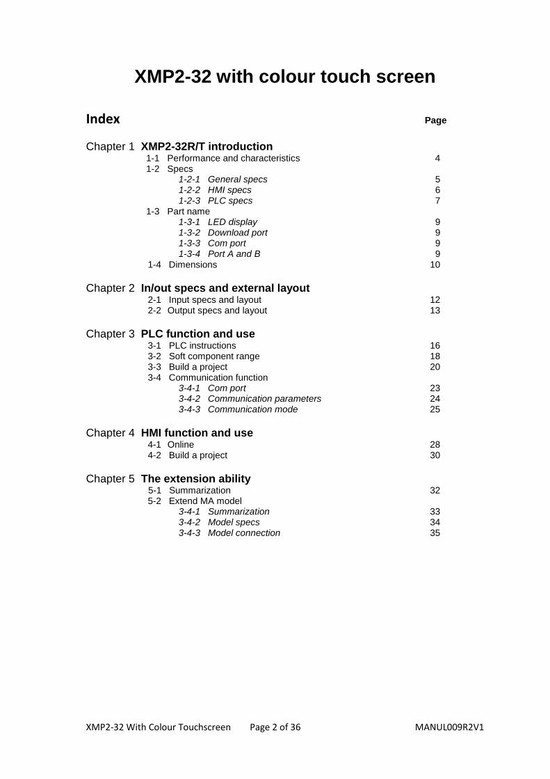
Index Page
Chapter 1 XMP2-32R/T introduction 1-1 Performance and characteristics 4 1-2 Specs 1-2-1 General specs 5 1-2-2 HMI specs 6 1-2-3 PLC specs 7 1-3 Part name 1-3-1 LED display 9 1-3-2 Download port 9 1-3-3 Com port 9 1-3-4 Port A and B 9
1-4 Dimensions 10
Chapter 2 In/out specs and external layout 2-1 Input specs and layout 12 2-2 Output specs and layout 13
Chapter 3 PLC function and use 3-1 PLC instructions 16 3-2 Soft component range 18 3-3 Build a project 20
3-4 Communication function 3-4-1 Com port 23 3-4-2 Communication parameters 24 3-4-3 Communication mode 25
Chapter 4 HMI function and use 4-1 Online 28
4-2 Build a project 30
Chapter 5 The extension ability 5-1 Summarization 32 5-2 Extend MA model 3-4-1 Summarization 33 3-4-2 Model specs 34 3-4-3 Model connection 35

XMP2-32 With Colour Touchscreen Page 3 of 36 MANUL009R2V1
1 XMP2-32 Introduction
XMP2-32R/T introduction
Model Function
XMP2-32R-E 16 DI, 16 DO Relay PLC, with a 7" colour TFT touch screen and 26 function keys, AC220V
XMP2-32R-C 16 DI, 16 DO Relay PLC, with a 7" colour TFT touch screen and 26 function keys, DC24V
XMP2-32T-E 16 DI, 16 DO Transistor PLC, with a 7" colour TFT touch screen and 26 function keys, AC220V
XMP2-32T-C 16 DI, 16 DO Transistor PLC, with a 7" colour TFT touch screen and 26 function keys, DC24V
1-1. Performance and characteristics
1-2.Specs
1-3. Parameters
1-4. Dimensions

XMP2-32 With Colour Touchscreen Page 4 of 36 MANUL009R2V1
XMP2-32 family is PLC+HMI integrators. This family has 4 models as listed above. The 4 models have the same aspect. Besides fulfilling the control requirements, XMP2-32 models can replace the common HMI and PLC in the control system. The compact shape saves space and also convenient for the maintenance engineer.
XMP2-32= MP760-T + XC2-32.
Integrate logic control, analogue input/output, HMI in one body Digital Input: 16 points. Digital Output: 16 points.
Brief and simple program interface.
HMI Part: 7" touch screen, true colour TFT, 256 colour, 480×234 pixel, LCD life can reach 50,000 hours.
26 Function Keys, sensitive and precise.
Supports high speed count, high speed pulse, external interruption.
Multi-function download port: Uses the same cable to download HMI and PLC program.
Waterproof level: IP20.
Compact size, saves space in the electric control cabinet.
1-1 Performance and characteristic’s

XMP2-32 With Colour Touchscreen Page 5 of 36 MANUL009R2V1
1-2-1 General specs
Input Voltage AC220V
Power Consumption Less than 10W (TYP2.0W)
Momentary Power-Off Allowance
Less than 20ms
Voltage Endurance AC1000V-10mA 1minute (between signal and ground)
Insulated Impedance DC500V about 10MΩ (between signal and ground)
Operating Temperature 0~50℃
Storage Temperature –10~60℃
Ambient Temperature 20~85% (No Dew)
Vibration 10~25Hz (X, Y, Z each direction 30 minutes 2G)
Anti-interference Voltage Noise: 1000Vp-p
Ambient Condition No corrosive gas
Protection Level IP20
1-2 Installation steps

XMP2-32 With Colour Touchscreen Page 6 of 36 MANUL009R2V1
1-2-2 HMI specs
Screen Property
Type TFT 256-colour LCD
Screen Dimension 7 inch
Use Life Over 50000 hours, 25℃, 24 hours running
Display Area 480*234
Contrast Not modifiable
Character setting English, Japanese,
Character size Free size and font
Touch mode Digital mode touch
Register Picture 8KB
Data 4KB

XMP2-32 With Colour Touchscreen Page 7 of 36 MANUL009R2V1
1-2-3 PLC specs
Item
Specs
XMP2-32R/T-E
Program executing format Loop scan format, time scan format
Program format Instruction, C language and ladder chart
Processing speed 0.5us
Power -off Retentive Use Flash ROM and Li battery
User program’s capacity 128KB
I/O points 16 digital input, 16 digital output
Internal coil (M) number 8512
Timer (T)
Points 640
Specs
100mS timer:Set time 0.1~3276.7 seconds
10mS timer:Set time 0.01~327.67 seconds
1mS timer:Set time 0.001~32.767 seconds
Counter (C)
Points 640
Specs
16 bits counter:set value K0~32767
32 bits counter:set value -2147483648~2147483647
Data Register (D) 2512 words
Flash ROM Register (FD) 512 words
High speed processing function High speed count、pulse output、external interrupt
Time Scan Interval Setting 0~99mS
Password protection 6 bits ASCII
Self-diagnose function Power on self-diagnose、Monitor timer、grammar check

XMP2-32 With Colour Touchscreen Page 8 of 36 MANUL009R2V1
1-3 Part names
Function keys
Display and touch area
Number keys
Power point
Product label
Input point Output point
Com Port
Download Port
USB CJ45 port
XMP2-32 With Colour Touchscreen Page 9 of 36 MANUL009R2V1
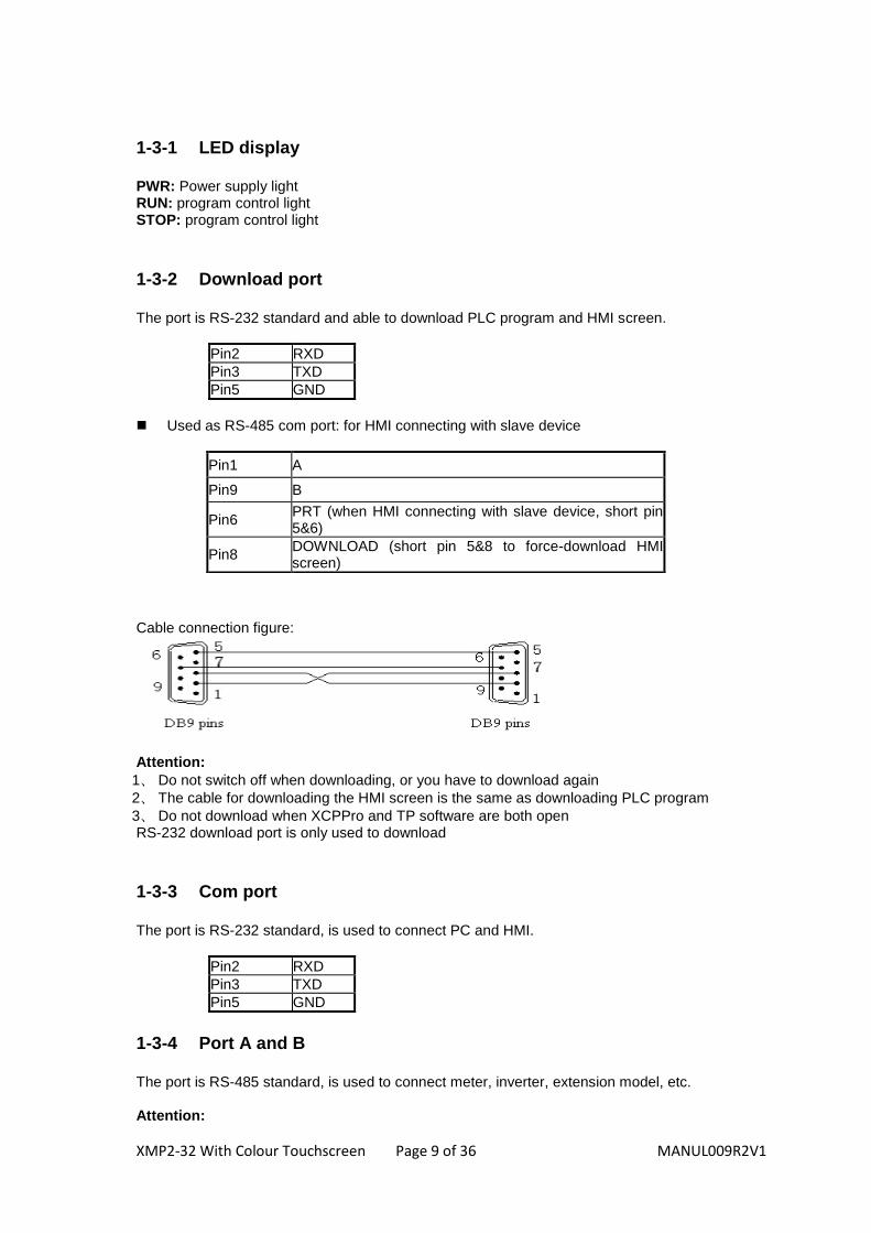
1-3-1 LED display PWR: Power supply light RUN: program control light STOP: program control light
1-3-2 Download port The port is RS-232 standard and able to download PLC program and HMI screen.
Pin2 RXD
Pin3 TXD
Pin5 GND
Used as RS-485 com port: for HMI connecting with slave device Cable connection figure:
Attention:
1、 Do not switch off when downloading, or you have to download again
2、 The cable for downloading the HMI screen is the same as downloading PLC program
3、 Do not download when XCPPro and TP software are both open RS-232 download port is only used to download 1-3-3 Com port The port is RS-232 standard, is used to connect PC and HMI.
Pin2 RXD
Pin3 TXD
Pin5 GND
1-3-4 Port A and B The port is RS-485 standard, is used to connect meter, inverter, extension model, etc. Attention:
Pin1 A
Pin9 B
Pin6 PRT (when HMI connecting with slave device, short pin 5&6)
Pin8 DOWNLOAD (short pin 5&8 to force-download HMI screen)

XMP2-32 With Colour Touchscreen Page 10 of 36 MANUL009R2V1
A, B port and RS-232 COM port is the same port, and cannot be used at the same time.
Outline dimension (mm):
Install dimension (mm):
1-4 Open and close XCP Pro

XMP2-32 With Colour Touchscreen Page 11 of 36 MANUL009R2V1
2 In/out specs and external layout
2-1. Input specs and layout
2-2.Output specs and layout
XMP2-32 With Colour Touchscreen Page 12 of 36 MANUL009R2V1
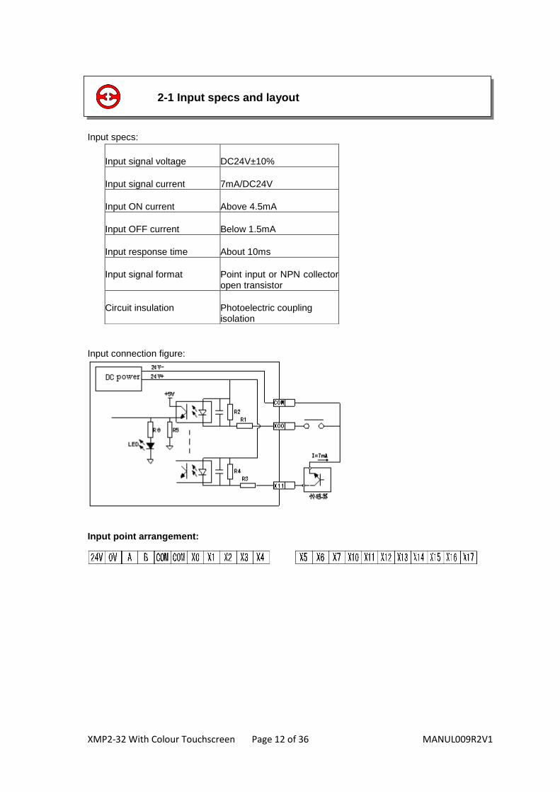
Input specs: Input connection figure:
Input point arrangement:
Input signal voltage DC24V±10%
Input signal current 7mA/DC24V
Input ON current Above 4.5mA
Input OFF current Below 1.5mA
Input response time About 10ms
Input signal format Point input or NPN collector open transistor
Circuit insulation Photoelectric coupling isolation
2-1 Input specs and layout

XMP2-32 With Colour Touchscreen Page 13 of 36 MANUL009R2V1
Relay output:
Internal power Below AC250V、DC30V
Circuit insulation Machine insulation
Action indication LED light
Max load
Resistor load 3A
Induction load 80VA
Light load 100W
Open circuit current No
Minimum load DC5V 2mA
Response time
OFF→ON 10ms
ON→OFF 10ms
Transistor output:
Internal power Below DC5~30V
Circuit insulation Optical coupling insulation
Action indication LED light
Max load
Resistor load 0.8A
Induction load 12w/DC24V
Light load 1.5W/DC24V
Open circuit current < 0.1 mA
Minimum load DC5V 2mA
Response time
OFF→ON 0.2ms
ON→OFF 0.2ms
2-2 Output specs and layout

XMP2-32 With Colour Touchscreen Page 14 of 36 MANUL009R2V1
Output connection figure:
Relay output:
Transistor output connection
Output point arrangement:

XMP2-32 With Colour Touchscreen Page 15 of 36 MANUL009R2V1
3 PLC functions and use
3-4. Communication function
3-1. PLC instructions
3-2.Soft component range
3-3. Build a project

XMP2-32 With Colour Touchscreen Page 16 of 36 MANUL009R2V1
XMP2-32R/T-E series product uses XC2 series PLC (the PLC instructions are the same as XC2-32). It contains SFC instructions, applied instructions and special function instructions. Please refer to XC Series PLC Operating Manual: I/O point definition and distribution. 1. High speed count (1) Increment mode: 5 channels
Channel Input Counter Highest frequency
CHL1 X0 C600 80KHZ
CHL2 X1 C602 80KHZ
CHL3 X3 C604 10KHZ
CHL4 X6 C606 10KHZ
CHL5 X11 C608 10KHZ
(2) Pulse + direction mode: 3 channels
Channel Input Pulse Direction
Counter Highest frequency
CHL1 X0 X1 C620 80KHZ
CHL2 X3 X4 C622 10KHZ
CHL3 X6 X7 C624 10KHZ
(3) AB phase mode: 3 channels
Channel
Input Phase B Phase A Counter Highest frequency
CHL1 X0 X1 C630 80KHZ
CHL2 X3 X4 C632 5KHZ
CHL3 X6 X7 C634 5KHZ
3-1 PLC instructions

XMP2-32 With Colour Touchscreen Page 17 of 36 MANUL009R2V1
2. High speed pulse output a) T type: Y0, Y1 available, the highest frequency is 400KHz b) RT type: Y0, Y1 available, the highest frequency is 400KHz c) R type: unavailable
3. Interrupt function
Channel Input Pointer tag Disable interruption instruction
Rising interruption Falling interruption
CHL1 X2 I0000 I0001 M8050
CHL2 X5 I0100 I0101 M8051
CHL3 X10 I0200 I0201 M8052
4. Frequency measurement The point is X1, X11, and X12.
5. Pulse width modulation The point is Y0, Y1.
1、T type: Y0, Y1 available
2、RT type: Y0, Y1 available
3、R type: unavailable
6. Precision timer 32-bit precise timer, the timer range is T600 to T618, matching with 10-interruption tag.

XMP2-32 With Colour Touchscreen Page 18 of 36 MANUL009R2V1
Soft component Name Range Point
X Input point X000~X017 (octal) 16
Y Output point Y000~Y017 (octal) 16
M Auxiliary relay
M0~ M2999
【M3000~M7999 】 8000
M8000~M8511 512
S Status S0~ S511
【S512~M1023 】 1024
T Timer
T0~T99:100ms not accumulation
40
T100~T199:100ms accumulation
T200~T299:10ms not accumulation
T300~T399:10ms accumulation
T400~T499:1ms not accumulation
T500~T599:1ms accumulation
T600~T618:1ms with interruption precise time
T620~T639:vacant
C Counter
C0~C299:16 bits forward counter
640
C300~C318:32 bits forward/back counter
【C320~C598】:32 bits forward/back counter
【C600~C618】:one phase high speed counter
【C620~C628】:Pulse + direction high speed
counter
【C630~C638】:AB phase high speed counter
D Data register
D0~D999
【D4000~D4999】 2000
For special using D8000~D8511 512
FD Flash ROM Register
FD0~FD255 256
For special use FD8000~FD8255
256
NOTE:
※The memory area in 【 】 is the defaulted power failure retentive area, the power failure
retentive area of soft components D, M, S, T, C can be set via FD register. For details, please see the following table.
※Flash ROM register needn’t be set for power failure retentive area,
※The serial number of input coil and output relay are octal data, other memory number are all
decimal data.
3-2 Soft component range

XMP2-32 With Colour Touchscreen Page 19 of 36 MANUL009R2V1
Address type
Area Function Default value Power failure memory area
D FD8202 First address of the power failure memory area of D
4000 D4000~D4999
M FD8203 First address of the power failure memory area of M
3000 M3000~M7999
T FD8204 First address of the power failure memory area of T
640 No set
C FD8205 First address of the power failure memory area of C
320 C320~C639
S FD8206 First address of the power failure memory area of S
512 S512~S1023
NOTE: Users can set the power failure memory area.

XMP2-32 With Colour Touchscreen Page 20 of 36 MANUL009R2V1
XMP2-32R/T-E series products are integrated with XC series PLC and HMI. When editing the PLC program, please use XCP Pro software, which is the same as XC series PLC.
1. Select the product type Open XCPPro, click “file---change PLC model”:
Select “XMP2-32”:
2. Editing the PLC program After selecting the type, user can edit the program in the software. The editing specs and operating details please refer to XC Series PLC Edit Software XCPPro Manual. The interface of software is as below:
3-3 Build a project
XMP2-32 With Colour Touchscreen Page 21 of 36 MANUL009R2V1
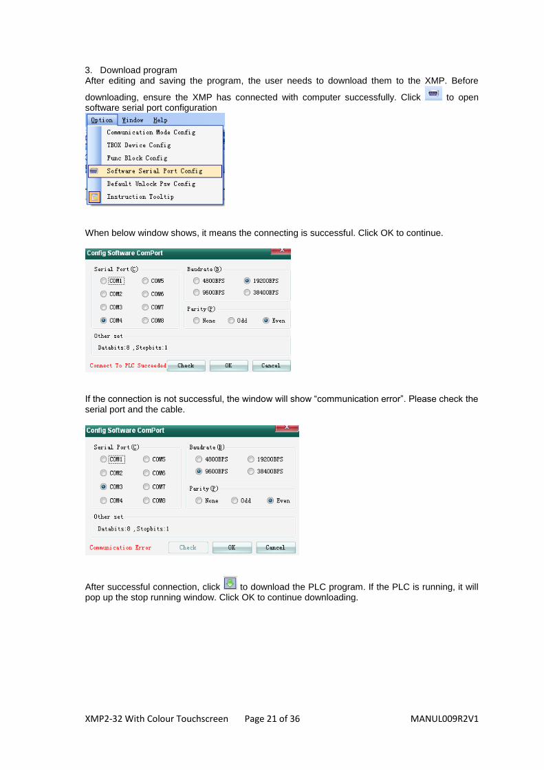
3. Download program After editing and saving the program, the user needs to download them to the XMP. Before
downloading, ensure the XMP has connected with computer successfully. Click to open software serial port configuration
When below window shows, it means the connecting is successful. Click OK to continue.
If the connection is not successful, the window will show “communication error”. Please check the serial port and the cable.
After successful connection, click to download the PLC program. If the PLC is running, it will pop up the stop running window. Click OK to continue downloading.

XMP2-32 With Colour Touchscreen Page 22 of 36 MANUL009R2V1
After downloading, click to run the PLC program.
4. Upload the program
If you want to check the PLC program in XP/XMP, click to upload the program to the PC.
Then click to save the program.

XMP2-32 With Colour Touchscreen Page 23 of 36 MANUL009R2V1
XMP2-32R/T series supports Modbus and free format communication. For instructions please refer to XC Series PLC User Manual.
3-4-1 Com port XMP2-32R/T series product has program port (DB9 pins port), RS-232 COM port (DB9 pins port) and RS-485 COM port (A and B point). Program port can only be used to download PLC program and HMI pictures. However, RS-232 and RS-485 COM port can be used to communicate with other devices. The communication parameters (baud rate, data bit, etc) can be set via software. RS-485 COM port point A means “+” signal, point B means “-” signal. Attention: RS-485 and RS-232 COM port are the same; do not use them at the same time.
3-4 Communication function

XMP2-32 With Colour Touchscreen Page 24 of 36 MANUL009R2V1
3-4-2 Communication parameters Communication parameters of RS-232 and RS-485 COM port can be set via FLASH register in the XMP. The defaulted parameters: Station 1, baud rate 19200bps, 8 data bits, 1 stop bit, even check
Station No. Modbus station No.: 1-254, 255(FF) is for free format communication
Baud rate 300bps~115.2Kbps
Data bit 8 or 7 bits
Stop bit 2 or 1 bits
Check Even, odd, no check
Communication parameters setting are as below table: Note: After changing the parameters in Flash register, a reboot is required .
COM Port
Number Function Description
FD8220
Communication mode
(Station number)
255 is free format,
1~254 is modbus station number
FD8221 Communication format Baud rate, data bit, stop bit, check
FD8222 ASC timeout judgment time Unit: ms, 0 means no timeout waiting
FD8223 Reply timeout judgment time Unit: ms, 0 means no timeout waiting
FD8224 Start symbol High 8 bits invalid
FD8225 End symbol High 8 bits invalid
FD8226 Free format setting 8/16 bits cushion, With/without start bit, With/without stop bit

XMP2-32 With Colour Touchscreen Page 25 of 36 MANUL009R2V1
0:300bps
1:600bps
2:1200 bps
3:2400 bps
4:4800 bps
5:9600 bps
6:19.2K bps
7:38.4K bps
8:57.6K bps
9:115.2K bps
0:8bits data
1:7bits data
0:2 stop bits
2:1stop bit
0:No check
1:Odd
check
2:Even
check
0:8 bits communication 1:16 bits communication
0: without start symbol 1: with start symbol
0: without end symbol 1: with end symbol
Reserved
0:300bps
1:600bps
2:1200 bps
3:2400 bps
4:4800 bps
5:9600 bps
6:19.2K bps
7:38.4K bps
8:57.6K bps
9:115.2K bps
Setting up communication
FD8221:
FD8226:
15 14 13 12 11 10 9 8 7 6 5 4 3 2 1 0
15 14 13 12 11 10 9 8 7 6 5 4 3 2 1 0
XMP2-32 With Colour Touchscreen Page 26 of 36 MANUL009R2V1
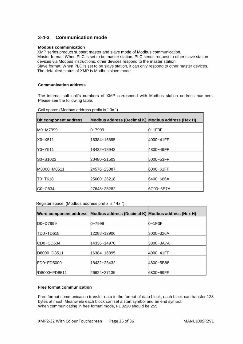
3-4-3 Communication mode Modbus communication
XMP series product support master and slave mode of Modbus communication. Master format: When PLC is set to be master station, PLC sends request to other slave station devices via Modbus instructions, other devices respond to the master station. Slave format: When PLC is set to be slave station, it can only respond to other master devices. The defaulted status of XMP is Modbus slave mode.
Communication address
The internal soft unit’s numbers of XMP correspond with Modbus station address numbers. Please see the following table: Coil space: (Modbus address prefix is “ 0x “)
Bit component address Modbus address (Decimal K) Modbus address (Hex H)
M0~M7999 0~7999 0~1F3F
X0~X511 16384~16895 4000~41FF
Y0~Y511 18432~18943 4800~49FF
S0~S1023 20480~21503 5000~53FF
M8000~M8511 24576~25087 6000~61FF
T0~T618 25600~26218 6400~666A
C0~C634 27648~28282 6C00~6E7A
Register space: (Modbus address prefix is “ 4x “)
Word component address Modbus address (Decimal K) Modbus address (Hex H)
D0~D7999 0~7999 0~1F3F
TD0~TD618 12288~12906 3000~326A
CD0~CD634 14336~14970 3800~3A7A
D8000~D8511 16384~16895 4000~41FF
FD0~FD5000 18432~23432 4800~5B88
FD8000~FD8511 26624~27135 6800~69FF
Free format communication Free format communication transfer data in the format of data block, each block can transfer 128 bytes at most. Meanwhile each block can set a start symbol and an end symbol. When communicating in free format mode, FD8220 should be 255.

XMP2-32 With Colour Touchscreen Page 27 of 36 MANUL009R2V1
4 HMI function and use
4-1.HMI function
4-2. Building a project

XMP2-32 With Colour Touchscreen Page 28 of 36 MANUL009R2V1
The HMI part of XMP2-32R/T-E series product is integrated with MP-760T touch screen. The faceplate key-presses are as below:
Key Function
Running the program, LED indication light
Stop running the program, LED indication light
Default main menu or most used screen.
Turn the screen to the last page
Turn the screen to the next page
Inquiry, jump to the user appointed screen
To write the modified value in the register and continue modifying next register.
Alarming list key. After setting the function of alarming list, press this key to jump to the alarm list screen.
Clear the selected area when modifying the register data.
Set the positive or negative of the data when modifying the register data.
Number key 0-9.
Function key F1-F6
NOTE: Besides the function listed in the previous table, all the keys can be defined as the function of “force ON”, “force OFF”, “reverse” or “momentary ON”.
4-1 HMI function

XMP2-32 With Colour Touchscreen Page 29 of 36 MANUL009R2V1
Please see below picture. Open TouchWin software, put a button or function button in the screen. Press, “enter” in the window, all the key-presses can be found in this menu. The user can set the key function as they need.

XMP2-32 With Colour Touchscreen Page 30 of 36 MANUL009R2V1
Use the Touchwin software.
1. Open the software, click File New or click to build a new project. 2. Choose “MP760-T (XMP-32)” in the panel window: 3. Click “next”; choose “XC Series” for PLC port device: 4. Click “next”; choose “XC Series” for download port device: Click “next” to complete the building.
The editing interface is as below: Note: For software user details please refer to TP Touch Screen User Manual.
After completing the project editing and saving, connect the download port of the XMP and
computer serial port with the downloading cable. Make sure the XMP power is on. Click or File Download to start downloading data, the download window is as below:
If it appears the item “connection overtime, check cable”, please download again.
4-2 Building a project

XMP2-32 With Colour Touchscreen Page 31 of 36 MANUL009R2V1
The downloading is completed when it shows the below window:
Attention: (1) Do not cut the power when downloading, or you have to download again. (2) The downloading cable for the TouchWin screen is the same as the downloading PLC program. (3) Do not download when XCPPro and TouchWin software are both open.

XMP2-32 With Colour Touchscreen Page 32 of 36 MANUL009R2V1
5 The extension ability
XMP2-32R/T series product cannot extend BD board. For extending other devices, use RS-232 or RS-485 (point A and B) COM port. RS-232 COM port can connect with the computer, HMI to monitor the program. RS-485 COM port can connect with meter, inverter, function model, etc. It can extend 32 external devices at most. Attention: The connection method is Bus mode, transmission line should start from station 1 to station 2, and then from station 2 to station 3…connect in this sequence until the last station. Star mode or ring mode connections are not permitted.
5-1 Summarization
5-1. Summarization
5-2.Extend MA model

XMP2-32 With Colour Touchscreen Page 33 of 36 MANUL009R2V1
XMP2-32R/T series product can extend MA model via RS-485 COM port (A and B point) in order to control and measure analog signals. The type and specs of MA model are as below: 5-2-1 MA model type
Type Function
MA-8DA 8 channels analog output, voltage 0-5V or 0-10V, current 0-20mA or 4-20mA
MA-7PT-P 7 channels PT100 temperature measurement control, PID adjustment inside
MA-8TC-P 8 channels K type thermocouple temperature measurement control, PID adjustment
5-2 Extend MA model

XMP2-32 With Colour Touchscreen Page 34 of 36 MANUL009R2V1
5-2-2 MA model specs MA-8DA:
Item Voltage Output Current Output
Analogue input range DC0~5V、0~10V
(External load resistor 2KΩ~1MΩ)
DC0~20mA、4~20mA
(External load resistor less than 500Ω)
Digital output range 10 bits binary data
Resolution 1/1024(10 bits)
Integrated Precision 0.8%
Scan speed 2ms per channel
COM port RS-485
Power supply for analogue usage
DC24V±10%, 100mA
Insulation Format DC/DC convert, optical coupling insulation
Installation format Can fix with M4 screw or install on DIN46277 (width: 35mm) track
Dimension 140W×73H×90D
MA-7PT-P:
Item Content
Analogue input signal Pt100 platinum resistor
Temperature measurement range
-100℃~350℃
Digital output range -1000~3500, 16 bits with symbol, binary
Control precision ±0.5℃
Accuracy 0.1℃
Integrated precision ±0.8% (relative max value)
Scan speed 100ms×7 channels
Power supply for analog DC24V±10%,50mA
Installation Format Fix with M4 screws or install on DIN46277 (width 35mm) track
Dimension 63mm×102mm×73.3mm
XMP2-32 With Colour Touchscreen Page 35 of 36 MANUL009R2V1
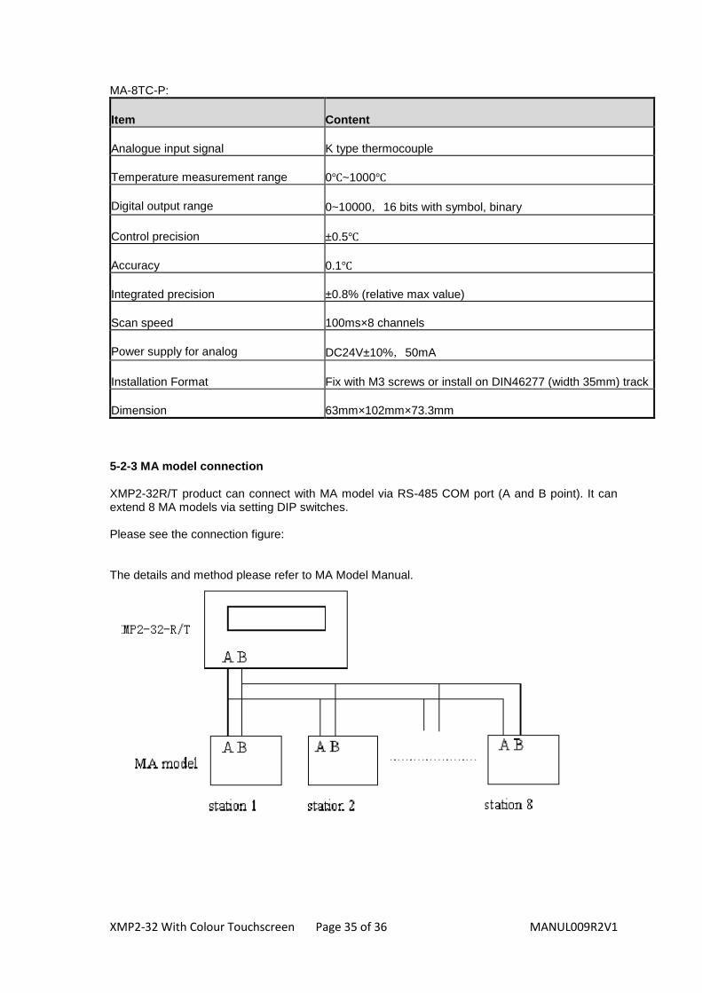
MA-8TC-P:
Item Content
Analogue input signal K type thermocouple
Temperature measurement range 0℃~1000℃
Digital output range 0~10000,16 bits with symbol, binary
Control precision ±0.5℃
Accuracy 0.1℃
Integrated precision ±0.8% (relative max value)
Scan speed 100ms×8 channels
Power supply for analog DC24V±10%,50mA
Installation Format Fix with M3 screws or install on DIN46277 (width 35mm) track
Dimension 63mm×102mm×73.3mm
5-2-3 MA model connection XMP2-32R/T product can connect with MA model via RS-485 COM port (A and B point). It can extend 8 MA models via setting DIP switches. Please see the connection figure: The details and method please refer to MA Model Manual.

XMP2-32 With Colour Touchscreen Page 36 of 36 MANUL009R2V1
Documentation Reference
Document Number Revision Date
MANU L009 R2 V1 05/07/2011
XINJE IS A REGISTERED TRADEMARK OF XINJE ELECTRICAL CO.LTD.
REPLICATION OF THE INFORMATION CONTAINED WITHIN THIS DOCUMENT WITHOUT PRIOR NOTIFICATION AND AGREEMENT IS PROHIBITED.
Engineered and supplied by:
International partners with:
Web: www.listo-ltd.com
www.xinje-support-centre-listo.com E-mail: [email protected] Please consider the environment before printing this document