xr-12c - extremausa.com · xr-12c extrema machinery company, inc. p.o. box 1450, albany, louisiana...
TRANSCRIPT

XR-12C
EXTREMA MACHINERY COMPANY, INC. P.O. BOX 1450, ALBANY, LOUISIANA 70711
(877) 398-7362 FAX (225) 567-2966

1
TABLE OF CONTENTS
Preface 3 SAFETY RULES
General Safety Rules 4 Electrical Safety Rules 6 Safety Rules for Maintenance 7 Warning Label 8
DIMENSIONS
Unpacking & Checking Contents 14 Shipping & Receiving Instructions 14 Accessories 15 Lifting the Machine 16 Installation Dimensions 17 Install the Machine 18 Cleaning the Machine & Rust Prevention 19 Connecting the Dust Collection 20 Connecting Power Source Wires 21
SPECIFICATIONS
Specifications 22 Legend of the Machine 23 Label Positions 24 Electrical Control Panel 27 Function Description for Electrical Control Panel 28 Electrical Specifications 30 Electric Units Current Consumption 30
OPERATION
Identification Before Operation 31 Operation Procedures 32 Starting Procedures 32 Lubricator 33 Adjust Height of Pressure Mechanism 36 Adjust Pressure for Pressure Roller 37 Adjust Feed Speed 38 Methods to Stop the Machine 39

2
TROUBLE SHOOTING
Trouble Shooting (Mechanical Section) 40 Trouble Shooting (Electrical Section) 42
SAW-BLADE
Select the Proper Saw Blade 43 Replacing the Saw Blade 44 Cutting Example 45 Adjusting the Position of Saw Blade 45 Notices for Work Piece Feeding 46
MAINTENANCE
Cleaning the Machine 47 Adjust V-belt Tension 47 Lubrication for Gear Reducer 48 Lubrication Instructions 49 Layout of Electric Control Box 51 Electric Supply Connection 52
PARTS LIST
Ordering the Replacement Parts 53 Parts List 54

3
PREFACE When it comes to tough straight ripping problems, we solve them in unique and practical ways. Our extensive experience in straight ripping technology is fully reflected in the high-performance EXTREMA Straight Line Rip Saw. The XR-12C produces straight, smooth and clean edges for perfect glue jointing jobs. All these features are compulsory for a modernized industrial production. Details of lubrication and maintenance are clearly described in this manual. Please read first before starting operation to avoid unnecessary damage.

4
GENERAL SAFETY RULES There is a certain amount of hazard involved with the use of woodworking machinery. Using the machine with the respect and caution demanded as far as safety precautions are concerned will considerably lessen the possibility of personal injury. However, if normal safety precautions are overlooked or ignored, severe personal injury to the operator can occur. 1. Read the operation manual before operating this machine. 2. If you are not thoroughly familiar with the machine operation, obtain advice from a
supervisor or other qualified person. 3. The machine should be disconnected from the power source before performing
maintenance or adjustments to the internal mechanisms, or when making repairs. 4. After maintenance job is finished, check to see if there are any tools or objects left on the
machine. Close all safety guards. 5. Before leaving the machine, make sure the work area is clean. 6. Check timber for loose knots, nails, or other items, which may cause a hazard or affect the
machine’s performance. 7. Learn the machine’s applications and limitations, as well as the specific potential hazards
peculiar to it. Keep the machine in top condition for best and safest performance. 8. Keep all guards in place and in working order. 9. Do not force the machine. It will do the job better and be safer working at the rate for which
it was designed. 10. All children and visitors should be kept a safe distance from the working area. 11. The operator should keep proper footing and balance at all times. 12. Do not operate the machine while under the influence of drugs, alcohol, or any other
medication. 13. Avoid awkward operations and hand positions where a sudden slip could cause your hand
to move into the cutterhead. 14. Never leave the machine until it comes to a complete stop, and never leave the machine
running unattended. 15. The employer is responsible for selecting competent and qualified employees. 16. The employer must make sure that employees study and utilize this safety information. 17. Supervisors must alert personnel of any unsafe practices they observe. 18. All employees should be aware of first aid facilities and be encouraged to use them,
regardless of the severity of the injury. 19. Fire prevention must be practiced and fire protection must be available to prevent loss of
life, personal injury, and property damage. 20. Safety shoes should be worn to provide protection against rolling objects, falling objects,
and sharp edges in the workplace. 21. Eye protection should be worn and such devices should be carefully selected, fitted and
used. Compulsory wearing of glasses with impact resistant lenses and side shields is a good safety policy. All eye protection should conform to ANSI 87 standards.
22. Wear hearing protection when operating the machine. 23. Do not wear rings, necklaces or jewelry around moving machinery. 24. Do not wear loose fitting clothes. Clothing should be comfortable, but long sleeves,
neckties, etc. should not be worn. 25. Do not wear gloves or other hand covering articles around moving machinery. 26. Cover long hair with a hair net or cap.

5
27. Protective guards and shields must be in place at all times unless they must be removed for specific service or maintenance. They should be immediately replaced when service or maintenance is completed.
28. Make sure that operator clearly knows how to stop the machine before starting work. 29. Never clean or remove chips while the machine is running. 30. Maintain the machine in good operating condition. Report unusual conditions or machine
malfunctions immediately. 31. Do not alter or remove guards and warning labels. 32. Keep the immediate area clean. Do not allow the floor to become slippery, or covered with
dust or obstacles. Dust that accumulates in the work area is a hazard that can cause you to fall or slip against the machine or its controls.
33. Employees should be required to report to their supervisors any hazardous condition of the machine or in the immediate area.

6
ELECTRICAL SAFETY RULES 1. Do not alter or bypass any protective interlock. 2. Before starting the machine, read and observe all warning labels and markings. 3. All electrical trouble shooting and repair should be undertaken by personnel properly
trained and have adequate knowledge and skill. 4. Use extra precautions in damp areas to prevent yourself from accidental grounding. 5. Make sure you and your tools are clear of possible electrical grounding. 6. The control panel doors should be opened only when it is necessary to check the electrical
equipment or electrical wiring. 7. Before supplying power to any equipment, establish without a doubt that all persons are
clear. 8. Be alert and stay focused on your work with no outside distractions. 9. Avoid wearing metal frame glasses or a metallic necklace or chain, and never work on
electrical equipment while wearing rings, watches, or bracelets. 10. When replacing conductors, make sure they conform to the manufacturer’s specifications,
including proper color-coding. 11. Do not alter the electrical circuits. The user is responsible for any machine damage caused
by an unauthorized alteration. 12. Always assume the electrical power is ON and treat circuit as live. This caution develops a
habit that may prevent an accident. 13. Give capacitors time to discharge. Otherwise, it should be done annually with care. 14. Use proper test equipment to make certain you have an open circuit. Test equipment must
be checked and calibrated at regular intervals. 15. Open the control panel doors only when necessary to check the electrical equipment or
wiring. After closing the door, make sure the disconnecting means are operating with the disconnecting handle mechanism in its proper position.
16. All covers on junction boxes must be closed before leaving any job.
7
SAFETY RULES FOR MAINTENANCE This machine has been factory inspected and tested before shipment so to ensure the dependable performance for years of operation. However, it is very important to perform periodical maintenance and cleaning. If any part becomes damaged or worn out, immediately repair or replace the part to prevent damage on the other mechanisms of the machine and prevent danger to the operator.
! WARNING 1. Unplug the electrical power before performing maintenance. 2. Pay special attention when replacing the saw blade.

8
WARNING LABEL LOCATIONS

9
WARNING LABEL
Warning Label (1)
Hazardous Voltage Unplug Power Before Servicing
The “Hazardous Voltage” label, shown in figure, is affixed to the electrical control box. The label warns service personnel to unplug the power supply before attempting any service on this machine.

10
WARNING LABEL
Warning Label (2)
DANGER
Sharp Saw Blade
The “Danger-Sharp Saw Blade” label, shown in figure, is affixed to the saw head. The label warns the operator and service personnel of the very sharp saw blade and to keep out of this area except for installing the saw blade.

11
WARNING LABEL
Warning Label (3)
! WARNING
Feed Work Piece From This End
The “Warning-Feed Work-Piece from This End” label, shown in figure, is affixed to the frame at the in-feed end. It alerts the operator that this is the in-feed end of the machine.

12
WARNING LABEL
Warning Label (4)
! Warning
Do Not Stand Against
The Feed Line
The “Warning-Do Not Stand Against the Feed Line” label, shown in figure, is affixed to the upper front of the machine base. It alerts the operator to stand out of the feed line while feeding work-pieces into the machine.

13
WARNING LABEL
Safety Instructions Label (5)
SAFETY INSTRUCTIONS
1. Do not operate the machine until all guards are in place.
2. Make sure the machine is properly grounded. 3. Do not wear necktie or loose clothes; wrap long hair. 4. Remove the accessories such as rings, watches or
bracelets, etc. 5. Wear safety glasses and other personal safety
equipment. 6. Unplug electric power before servicing. 7. Do not leave machine running unattended. 8. Refer to instruction manual for complete setup,
operating, and servicing.
The “Safety Instructions” label, shown in figure, is attached to the front of the machine frame. The label provides convenient safeguard instructions for the operator and service personnel.

14
UNPACKING & CHECKING CONTENTS The machine has been well packed at the manufacturer’s factory and shipped in good condition. The machine is shipped in one wooden pallet. Upon receiving the machine, carefully unpack it and check all items as according to the packing list. If you find any part is missing or damaged, contact your local distributor immediately or the manufacturer of the machine. Do not attempt to operate the machine until the missing parts are obtained and are installed correctly. SHIPPING & RECEIVING INSTRUCTIONS This machine has been carefully inspected and tested before packing. It was delivered in good condition and was shipped in one wooden pallet. When receiving this machine, inspect the wooden case and check to see if there is any damage on the wooden pallet. Then check the machine and all items as according to the packing list. If there is any damage on the machine or any missing parts, report it to your local distributor or the machine manufacturer immediately.

15
ACCESSORIES The machine comes with the following accessories: 1. Tool box 1-pc. 2. Oil pot 1-pc. 3. Open-ended wrench 11*13 1-pc. 4. Open-ended wrench 12*14 1-pc. 5. Hex. wrench set 1-set 6. Hex. wrench 10mm 1-pc. 7. Supplied gandle 1-pc. 8. Screw M12*50 4-pc. 9. Nut M12 4-pc. 10. Steel pad 4-pc. 11. Fence 1-set

16
LIFTING THE MACHINE The machine should be lifted or moved by a forklift. Make sure the loading capacity of the forklift is sufficient to raise the machine. Pay special attention to balance while lifting the machine to prevent dropping the machine. The forks of the forklift must protrude from the machine bottom for uniform distribution of the entire machine weight. If there is an electric hoist in the factory, lift the machine by the two lifting rings.

17
INTSTALLATION DIMENSIONS It is suggested to leave at least 1000mm more than the length of the machine to facilitate work-piece handling.

18
INSTALL THE MACHINE The machine does not need to be bolted into the concrete floor, but needs a solid, level concrete floor. Leave proper space around the machine for conveniently handling the materials to be cut. See the instruction on Installation Dimensions. Four steel pads are furnished with the machine, which are to be placed under the leveling screws at the corners under the machine base. Make leveling adjustments after the machine has been located to the work site. ! WARNING: 1. Do not install the machine in a dangerous environment. 2. Do not use the machine in a damp or wet location, or expose to rain. 3. Keep the work well lit.

19
CLEANING THE MACHINE & RUST PREVENTION Once the machine has been unpacked, check to see if the machine and all parts have been shipped correctly as according to the packing list. Make sure there is no damage or parts missing. Clean off the rust prevention oil coated on the machine. CONNECTING THE DUST COLLECTION DEVICE The top of the machine is equipped with a dust outlet, which is to be connected to the dust collector by using a flexible hose. The dust outlet is 5” in diameter. Do not operate this machine until the dust collector is running, which may prevent a dust jam affecting the operation performance of the machine. NOTE: The length of flexible hose should not exceed 6 feet. Flexible hose that is too long may affect the cutting performance of the machine and the quality of the cut.

20
CONNECTING POWER SOURCE WIRES The machine needs a three-phase, AC power source. Be certain that the correct power wires are connected to the correct connection points. This can be identified by checking the saw blade running direction which should be the same as the arrowhead instruction. If it runs to the opposite direction, change any two of the three power wires for obtaining the correct running direction. Proceed with the electrical wiring as according to the Electrical Wiring Diagram. All electrical trouble-shooting and repair should be undertaken by personnel properly trained and have adequate knowledge and skill. Always close the electrical control panel door to prevent dust from entering into it, as this may cause damage to the electric circuit. The output wires should be correct in size as rated. Avoid wetting. CONNECT THE POWER WIRES 1. Power Supply 3 phase, 230V/60HZ. 40 Amps
Voltage is specified by customers The setup environment is effective for EMI, but should be separate from other machines or facility. Keep the voltage variation in 10%.
2. Current Saw Blade Drive Motor: 15HP The rated current is 37 A.
3.Circuit Breaker According to the current to select its suitable breaker, applying to the standards of IEC or VDE.

21
SPECIFICATIONS Max. Working Thickness 3.35” Min. Working Length 8” Distance Between Saw & Column 14 ¾” Saw Arbor Diameter 1” Saw Blade Diameter 12” (10-85mm) Feed Speed (Variable) 50-90 ft/min Saw Arbor Speed 4500 RPM (60HZ) Arbor Motor 15 HP Feed Motor 1 HP Table Area (L x W) 53.35” x 30.34” Table Height 32 ½” Dust Outlet Diameter 4” x 1 Machine Dimension 61 2/5” x 36 6/10” x 54 1/3” Gross Weight 2600 lbs

22
LEGEND OF THE MACHINE

23
LABEL POSITIONS

24
LABEL

25
LABEL

26
ELECTRICAL CONTROL PANEL Link chain conveyor Saw blade start Power source start switch switch switch Power indication lamp Power Lamp Feeder Spindle Power Off Off Stop A Link chain conveyor Saw blade stop Emergency stop Amp Meter
stop switch switch switch for saw drive motor

27
FUNCTION DESCRIPTION FOR ELECTRICAL CONTROL PANEL
Switch Figure Switch Name Function 1. POWER LAMP
Power Indication Lamp When this lamp lights the machine is under power.
2.
POWER
Power Source Switch When this switch is pressed, the machine is under power and ready for operation.
3. STOP
Emergency Stop Switch During operation, if any abnormal motion occurs, press this switch to stop all motions of the machine immediately.
4.
A
Amp. Meter for Saw Motor
The Amp. Meter indicates the cutting load of the motor.
5.
SPINDLE
Saw Arbor Start Switch Press this switch to start the saw arbor
6. OFF
Saw Arbor Stop Switch Press this switch to stop saw arbor.

28
Switch Figure Switch Name Function 7.
FEEDER
Link Chain Conveyor Start Switch
Press this switch to start link chain conveyor. If the saw arbor does not start, this switch will not work.
8.
OFF
Link Chain Conveyor Stop Switch
Press this switch to stop link chain conveyor.

29
ELECTRICAL SPECIFICATIONS Item
Name Specification Terminal Model
MS1 Magnetic Contactor AC3 35A 440V TE LC1D2510 MS2 Magnetic Contactor AC3 25A 440V TE LC1D1801 MS3 Magnetic Contactor AC3 35A 440V TE LC1D2501 MS4 Magnetic Contactor AC3 18A 440V TE LC1D1210 OL1 Overload 12A~18A TE LR1D1321 OL2 Overload 4A~8A TE LR2D1514 T1 Air Time 0.1~30S LA2DT1 R1 Relay 5A250AC OMRON MY-2
TB1 Terminal 50A 600V MAX MACK IN30BK TB2 Terminal 30A 600V MAX MACK IN20BK TB3 Terminal 15A 600V MAX MACK IN13S BK PB1 Power LP 220V YK 10 PB2 Power Start 5A 220VAC TE XB2-BW3361 PB3 Power Stop 5A 220VAC TE XB2-BA21 PB4 Saw Start 5A 220VAC TE XB2-BW3361 PB5 Saw Stop 5A 220VAC TE XB2-BA21 PB6 Conveyor Start 5A 220VAC TE XB2-BW3361 PB7 Conveyor Stop 5A 220VAC TE XB2-BA21 PB8 E-Stop 5A 220VAC TE XB2-BS542 PT Transformer 230V/460V/110V/220 SL-96
PA1 Current Meter YIO LVEN YL-60P FI Fuse TEND TFB-101
ELECTRIC UNITS CURRENT CONSUMPTION Description Qty Specification Saw Blade Drive Motor 1 15HP 4P 3PH
230V 60HZ 37A 11KW
Feed Drive Motor 1 1HP 4P 3PH 230V 60HZ 3A 0.75KW
Lubricator 1 80W
30
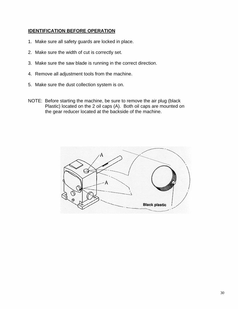
IDENTIFICATION BEFORE OPERATION 1. Make sure all safety guards are locked in place. 2. Make sure the width of cut is correctly set. 3. Make sure the saw blade is running in the correct direction. 4. Remove all adjustment tools from the machine. 5. Make sure the dust collection system is on. NOTE: Before starting the machine, be sure to remove the air plug (black Plastic) located on the 2 oil caps (A). Both oil caps are mounted on the gear reducer located at the backside of the machine.

31
OPERATION PROCEDURES 1. Install the saw blade onto the saw head as according to the instructions for saw blade
installation. 2. Close the guard on the dust outlet. Retract the pressure roller and return saw blade to its
original position by using the corresponding switch. Then close the door on the machine frame.
NOTE: If the door is not closed, the machine cannot be started. 3. Start the link chain conveyor and the saw blade running and keep them running for a while.
At this time check if the machine is running normally. Also, check to see if the automatic lubrication systems for the link chain conveyor and the saw blade are functioning normally.
4. Make a trial cut at a low speed. Inspect the thickness of the product. If necessary, make
further adjustments for thickness of cut. STARTING PROCEDURES 1. Press the power source switch. The machine is then ready for operation. 2. Press the saw arbor start switch to start the saw arbor. 3. Press the link start switch. If the saw arbor is not started, this feed start switch is not
effected.

32
LUBRICATOR Check the lubricator everyday to ensure it is functioning normally at all times. Otherwise, a lubrication failure may cause serious damage to the machine. If the lubricator is damaged, stop the machine operation immediately to prevent damage on the link chain conveyor due to lack of lubrication. For the adjustment of the flow volume, set the “ON” and “OFF” at the respective position for the selected discharge amount, and the operation is simple. If continued or more lubricating is required please activate the coercive pumping switch. OIL FEEDING INSTRUCTIONS: 1. Press the “F” key in order to fill up the pipe with oil. 2. If continued lubricating is required, press the “F” key. At that time, the “ACT” indicator is lit
and pumping oil. 3. Pressing the “F” key does not influence the time intervals. 4. The maximum time interval for pumping oil is 4 minutes. SETTING TIME INTERVALS: 1. Set the “ON” and “OFF” at the respective positions for the selected discharge amount. 2. Set the position of time not exceeding 0-60 or 0-180. 3. The “OFF” time should be more than triple the “ON” time. 4. Time value in +3%. 5. The “ACT” indicator will light during the activating phase. 6. The “INT” indicator will light during the intermittent phase. • When the oil is lower than the minimum level, the “ACT” and “INT” lamps will flicker; the
motor will stop. “ALM” will ring. At this time, refill with clean oil. The time of detection when oil is needed is 30 seconds.
The oil flows from the lubricator to the oil distributor, then to all lubricating points of the machine. The connectors (1), (2), and (3) on the oil distributor are used for controlling lubrication to brushes (1), (2), and (3). Connectors (4) and (5) are used for controlling lubrication to chain rails (1) and (2).

33
LUBRICATOR Recommended Lubrication:
VISCOUSITY AMBIENT TEMP. SHELL ISO 32 O-5 degrees Tonna 32 BG 32 68 5-40 degrees Tonna 68 BG 68
1. Fill with new oil only. Do not use any reclaimed oil. 2. Keep interior of oil box clean. 3. The lubricator is a critical part of the machine. A proper lubrication for the link chain
conveyor is an important factor for ensuring the accuracy of the machine. Make sure the lubricator works normally and lubrication at the bottom of the link chain conveyor is proper.

34
LUBRICATOR

35
ADJUST HEIGHT OF PRESSURE MECHANISM 1. Loosen the lock handle (1). 2. Turn the hand wheel (2) for adjusting the height position of pressure mechanism. 3. Tighten the lock handle (1). 4. The thickness of work piece is indicated by the indicator (3). The position of the pressure
roller is 3/32” lower than the indicator. See Fig. 1. 5. The height adjustment of pressure mechanism is decided by the thickness of cut. When
cutting a thicker work piece, the indicator can be adjusted to 2-4mm lower than the work piece for increasing the loading pressure of spring.
ADJUSTMENT EXAMPLE:

36
ADJUST PRESSURE FOR PRESSURE ROLLER Adjust the pressure for the pressure roller as follows: 1. Turn the adjustment screw clockwise to increase the pressure for pressure roller. Loosen
the lock on the adjustment screw before adjusting the pressure. Tighten it securely after the pressure is adjusted.
2. Turn the adjustment screw counter-clockwise to decrease the pressure for pressure roller.
Loosen the lock on the adjustment screw before adjusting the pressure. Tighten it securely after the pressure is adjusted.

37
ADJUST FEED SPEED 1. Start the caterpillar chain. 2. Loosen the lever (1). 3. Properly adjust the feed speed by shifting the lever (2) rightward and leftward. 4. Tighten the lever (1) securely. 5. The feed speed adjustment is dependent upon the wood material and thickness of cut. For
setting up a cut on new wood or thickness of wood, it is suggested to feed it at a low speed, then try to increase the feed speed until a proper feed speed is decided. The feed speed can be identified by the cutting noise, vibration and current consumption on the saw arbor drive motor.

38
METHODS TO STOP THE MACHINE If any accidents occur, use the following switches to stop the machine. It is very important to understand the functions of the switches as shown below: 1. Saw Blade Stop Switch:
1. Reverse the machine starting procedures for stopping saw blade.
2. Press this switch to stop the saw blade. 2. Link Chain Conveyor Stop Switch.
Press this switch. The link chain conveyor and the work piece feeding stops. 3. Emergency Stop Switch:
Press this switch; all motions stop immediately. NOTE:
1. The emergency stop switch is pressed only in emergency situations. Wait until the machine comes to a complete stop. Open the pressure mechanism and remove the jammed piece of wood. Reset the pressure mechanism and restart the machine.
2. Do not press the emergency switch while in normal operation.

39
TROUBLE SHOOTING (MECHANICAL SECTION)
TROUBLE CAUSES CORRECTION
Saw arbor can’t start.
Saw arbor guard or rear guard not closed.
Check and close guards.
Conveyor can’t run.
Variable speed belt too loose or dropped.
Adjust variable speed belt tension or replace it.
When saw arbor switch pressed, saw arbor can’t run and noise comes from motor.
Fix pin not removed, after saw blade is changed.
Remove it.
Work piece slips.
Pressure roller is too high.
Lower pressure roller.
Convex cut causes jointing failure.
1. Saw blade is too dull. 2. Fence is out of
alignment.
1. Replace saw blade. 2. Adjust fence. Refer to
fence adjustment instructions.
Concave cut causes jointing failure.
1. Saw blade is too dull. 2. Fence is out of
alignment.
1. Replace saw blade. 2. Adjust fence. Refer to
fence adjustment instructions.
Uneven product thickness at front and rear end.
1. Saw blade is too dull. 2. Fence is out of
alignment.
1. Replace saw blade. 2. Adjust fence. Refer to
fence adjustment instructions.

40
TROUBLE CAUSE CORRECTION
Abnormal speed of link chain conveyor.
1. There is no oil in
lubricator. 2. Oil distributor is
jammed. 3. Variable speed belt
loosened. 4. There is no oil in gear
reducer.
1. Fill oil. 2. Blow off dust with air
gun. Refer to lubricator adjustment instructions.
3. Adjust tension of variable speed belt.
4. Fill oil.
Wood is not cut, or waste material.
Saw blade position is too high to cut a notch into chain block.
Lower saw blade. Refer to saw blade adjustment instructions.
Insufficient power causes saw blade to stop.
1. Use improper saw
blade. 2. Saw arbor belt
loosened.
1. Use correct saw
blade. Refer to saw blade selection instructions.
2. Adjust saw arbor belt tension.
Poor square accuracy of product after cut.
Damage caused by poor lubrication on chain rail and chain block.
Replace chain rail and chain block.
Power lamp light on, but machine can’t start. Motion can’t start.
1. Check if emergency
stop switch is normal or not.
2. Safety door cover not closed.
3. Overload relay tripped.
4. Poor starting switch of motor.
1. Change connection
point, and check push button.
2. Close safety door cover.
3. Replace R1. 4. Replace MS1, MS2.
Power lamp light on, but machine can’t start. Motor starts but does not remain on.
Poor stop push button
1. Check PB2, PB3.
Replace push button. 2. Replace magnetic
switch.

41
ADJUSTING FENCE

42
TROUBLE SHOOTING (ELECTRICAL SECTION)
TROUBLE CAUSE CORECTION Power can’t turn on. No power.
1. Check three phase
power source. 2. Motor overload relay
tripped. 3. Blown fuse.
1. Check power source. 2. Reset overload relay. 3. Replace fuse.
Power can’t turn on. Lack of phase.
1. Check power source. 2. YL-60P wire broken. 3. Poor connection on
magnetic switch. 4. Poor connection on
terminals. 5. Screw loosened.
1. Check three phase
power source. 2. Replace YL-60. 3. Replace magnetic
switch. 4. Replace TB1, TB2. 5. Tighten screw.
Motor can’t run. Running abnormally.
1. Motor damaged. 2. Magnetic switch
damaged. 3. Motor jammed.
1. Replace motor. 2. Clean motor.
Motor can’t run. Motor failed.
1. Magnetic switch
damaged. 2. Motor burnt out.
1. Replace magnetic
switch. 2. Replace motor.

43
SELECT THE PROPER SAW BLADE The specification of saw blade may affect the cutting efficiency and operation safety. Select the proper saw blade according to the hardness of wood material and thickness of cut. 1. NORMAL TEETH: Suggested for cutting dry, hard material, the thickness of cut is medium
or thin. 2. BIG PITCH OF TEETH: Suggested for cutting soft or oil contained thick material. 3. The pitch of teeth may avoid teeth damage resulting from a dust deposit. 4. SAW BLADE SPECIFICATIONS:
Bore: 1” Outside Diameter: 10” – 12” (250-305mm)
5. TRIMMING SAW BLADE:
12” (OD) x 4mm (thick) x 48T-36T 6. SPLIT SAW BLADE:
12” (OD) x 3mm (thick) x 36T-24T

44
REPLACING THE SAW BLADE 1. Turn off and lock out the power, and make sure the saw blade has come to a complete
stop. 2. Loosen the saw arbor lock lever (2). Open the cover on pressure mechanism. Raise the
saw arbor by turning the saw arbor raising hand wheel (3) until the teeth are 5-10mm higher than the conveyor to avoid teeth damaged by the conveyor. Loosen the wing nut (6) on the small pressure roller (5), then move away the small pressure roller (5).
3. Open the rear door. Fit the supplied gandle (1) into the cross slot on the pulley for fixing the saw arbor.
4. Loosen the screw (4), then take out the front clamping plate (7). 5. Take out the saw blade. 6. The saw blade teeth should be 1/32”-1/8” lower than the conveyor, but should not be over
1/8”. 7. Always keep the saw blade sharp to reduce the cutting load, and ensure the service life of
the machine.
CUTTING EXAMPLE Cutting capacity of the machine:
Thickness range of wood: ¼”-3 5/16” Maximum width of cut: 14 3/8” Minimum length of cut: 8”
Do not feed the wood with dimensions out of above ranges to avoid damage on the machine or serious injury on the operator.

45
ADJUSTING THE POSITION OF SAW BLADE Close the safety door. Start the saw blade running. Slowly lower the saw arbor until it cuts into the rubber 1mm.
The saw blade should be 1/32”-1/8” lower than the chain conveyor. If saw blade is higher than the chain conveyor, the wood can’t be cut.

46
NOTICES FOR WORK PIECE FEEDING 1. Place the skin of wood at topside as shown in Fig. 1-A. If it is placed at the bottom, shown
in Fig. 1-B, then the soft part of the wood will be clamped by the rollers which may affect the feeding smoothness and cutting accuracy.
2. When cutting a warped work piece, place it as shown in Fig. 2-A. Don’t place it as shown
in Fig. 2-B because it may affect feeding smoothness and cutting accuracy.
Place the wood skin at topside. (CORRECT)
Fig. 1-A
The convex side of wood is placed upward. (CORRECT)
Fig. 2-A
Place the wood skin at bottom. (WRONG)
Fig. 1-B
The convex side of wood is placed downward. (WRONG)
Fig. 2-B

47
CLEANING THE MACHINE The machine needs to be cleaned everyday after operations are finished. Use a compressed air for cleaning the link chain conveyor, and inside mechanisms such as saw heads, etc. The link chain conveyor needs to be coated with a thin film of oil. ADJUST V-BELT TENSION 1. After a long period of operation, the machine’s v-belt may have gradually become
loosened. At this time it is necessary to adjust the v-belt tension. 2. Disconnect and lock out the machine from the power source before adjusting the v-belt
tension. 3. Open the side door of the machine. 4. Turn the v-belt tension adjustment screw (1), (2) on the motor base for adjusting the v-belt
tension. 5. Reverse the above procedures after the v-belt tension has been properly adjusted.

48
LUBRICATION FOR GEAR REDUCER To ensure the gear reducer develops its normal performance, it is important to select proper viscosity of lubrication oil to fill into the gear reducer. This will provide smooth friction between gears, high impact resistant performance, and allow high load cutting.
LOAD
AMBIENT TEMP.
SHELL OIL
MOBIL OIL
ISO VG
Mild Load
0-5 degrees C
Omala Oil 150
Mobil Gear 629
ISOVGEP 150
Mild Load
5-40 degrees C
Omala Oil 320
Mobil Gear 632
ISOVGEP 320
Mild Load
40-65 degrees C
Omala Oil 460
Mobil Gear 634
ISOVGEP 460
NOTICES: 1. Change the oil after the initial 100 hours of operation. Also, at this time, clean the interior of
the gear reducer. Afterward, change the oil every 2500 hours of operation. 2. When the gear reducer is used for high speed cutting, in high temperature working
environment, or heavy load cutting, or when forced lubrication system is required, contact us for further lubrication instructions.
3. Note that insufficient oil may cause noise and fast wear of gears. 4. Excessive oil filled into the gear reducer may cause oil leakage. 5. Fill oil into the gear reducer until the oil level reaches over half of its full capacity.

49
LUBRICATION INSTRUCTIONS
LUBRICATION POINTS
METHODS
LUBRICANTS
FREQUENCY
1. Oil cups at arbor and
both ends of slot pieces
Fill oil
Shell slide oil T68 (Sliway Tonna 68) EXTREMA Oil
Once daily
2. Elevation screw under
bevel gear box
Greasing with brush
Grease
Once monthly
3. Flange bearing under
hand wheel
Grease gun
Shell grease R2 (Grease Alvania R2) EXTREMA Oil
Once per two weeks
4. Two grease nipples
on the arbor
Grease gun
Grease
Once monthly
5. Oil box of lubricator
Fill oil
Shell slide oil T68 (Sliway Tonna 68)
Fill oil when alarm sounds
6. Flange bearing of
chain wheel
Grease gun
Shell grease R2 (Grease Alvania R2)
Once per two weeks
7. Screw near the arbor
Greasing with brush
Grease
Once daily
8.Oil box of gear reducer
Fill oil
Shell Omala 320
Once monthly
9. Two grease nipples
on the left small pressure roller arm
Grease gun
Grease
Once weekly

50
LUBRICATION LOCATIONS

51
LAYOUT OF ELECTRIC CONTROL BOX MS4 MS2 MS3 MS1 OL2 R1 OL1 F1 F2 1 9 8 0 W3 V3 U3 V2 U2 W2 W1 V1 U1 R S T
PT-95

52
ELECTRIC SUPPLY CONNECTION

53
ORDERING THE REPLACEMENT PARTS All parts listed may be ordered directly from your local distributor or the manufacturer of the machine. When ordering the replacement parts, always give the following information:
1. Date of manufacturing
2. Machine model number
3. Parts number
4. Required quantities

54
A: BASE ASSEMBLY

55
A: Base Assembly
No Part Description Qty Part No 1 Base 1 365001 2 Spring 1 365104 3 Rear Chain Wheel Guard 1 365103 4 Flanged Bearing UCP205 4 BUCP205 5 Rear Chain Wheel 1 365016 6 Gear Reducer 1 365013 7 Pulley (Gear Reducer) 1 365014 8 Center Screw 2 365011 9 Saw Arbor Motor Base 1 365003 10 Saw Arbor Motor 1 MC10H4P 11 Motor Base Collar 1 365135 12 Motor Pulley 1 365004 13 Feed Motor Guard 1 365105 14 Variable Pulley 1 365013-2 15 Feed Drive Motor 1 MC1H4P 16 Stop Collar 1 365007-2 17 Feed Motor Base 1 365006A 18 Dust Removing Brush 3 365010A 19 Dust Hood 1 365114 20 Front Door 1 365100 21 Adjustable Rocker Arm 1 365008 22 Handle 1 HTR1230 23 Front Chain Wheel Guard 1 365102 24 Electrical Control Box 1 365PF001 25 Plastic Handle (With Screw) 1 HEN8010 26 Front Chain Wheel 1 365017 27 Front Chain Wheel Shaft 1 365018 28 Chain Block Front Guard 1 365024 29 Lubrication 1 OSDE-2L 30 Oil Distributor 1 O365 31 Motor Guard 1 365105 32 General Purpose Units 1 GAC1/4 33 Brake 1 650D052-1 34 Electro-Magnetic Valve 1 GAV1/4 35 Arbor Flange 1 365175 36 Arbor Flange 1 365176 37 Fixed Stock 1 365178 38 Control Box 1 365126 39 Fixed Shaft 1 365181 40 Brake Fixture 1 365180

56
B: UPPER ASSEMBLY

57
B: Upper Assembly
No Part Description Qty Part No 1 Upper Mechanism 1 365029 2 B1: Saw Arbor Assembly 1 B1 3 Fix Shaft 1 365030 4 Fix Collar 1 365031 5 Supplied Handle 1 365115 6 Lock Screw 1 365054 7 Elevation Nut 1 365068 8 Lifting Ring 2 SBN12 9 Rear Cover 1 365107 10 Handle 1 HTRM12 11 Saw Arbor Raising Assembly 1 365056A 12 Handle Wheel 1 365049 13 Saw Arbor Raising Nut 1 365047 14 Flanged Bearing BLFL-207 1 BLF207J 15 Saw Arbor Raising Screw 1 365048 16 Lock Nut 1 320063 17 Washer 2 650D200 18 Hexagonal Socket Head Screw M8x20 2 SC820 19 Retaining Ring External S-35 1 SCS35 20 Handle Wheel 1 HCB200

58
B1: SAW ARBOR ASSEMBLY
B1: Saw Arbor Assembly
No Part Description Qty Part No 1 Quill 1 365032 2 Spacer 1 365043 3 Saw Arbor Rear Cap 1 365044 4 Saw Arbor Pulley 1 365045 5 Washer 1 365046 6 Bearing Lock Nut 1 SAN08 7 Bearing Spacer 1 365039 8 Saw Arbor Front Cap 1 365036 9 Saw Arbor 1 365033 10 Bearing 7208CDB/GL P5 2 B7208CDP5 11 Bearing 6306-NK (NSL) 1 B6306N 12 Bearing Spacer 1 365038 13 Teeth Washer 1 SAW08 14 Saw Blade Front Clamping Plate 1 365035 15 Socket Head Cap Screw M12x45 1 SC1245 16 Motor Base 1 365136 17 Saw Blade 1 365PH

59
C: LINK CHAIN CONVEYOR ASSEMBLY
C: Link Chain Conveyor Assembly
No Part Description Qty Part No 1 Rail 1 365019 2 Conveyor Chain 1 365021 3 Chain Block 36 365022 4 Rubber 36 365022-A

60
D: PRESSURE ASSEMBLY
D: Pressure Assembly
No Part Description Qty Part No 1 Pressure Mechanism 1 365066 2 Door (Pressure Mechanism) 1 365070 3 Plastic Knob 1 HENF6312 4 Door Latch 2 365069 5 D1: Big Pressure Roller Assembly 2 D1 6 D2: Small Pressure Roller Assembly 1 D2 7 D3-1: Small Pressure Roller Assembly 1 D3-1 8 D3-2: Small Pressure Roller Assembly 1 D3-2 9 Pressure Roller Shaft 4 365077
10 Fix Shaft 1 365084 11 Anti-Kickback Finger Shaft 1 365099 12 Anti-Kickback Finger Shaft 1 365094 13 Anti-Kickback Finger Shaft 1 SW2028 14 Slide Piece 1 365067 15 Scale Holder 1 365133 16 Handle 1 HTR1230 17 Cover 1 365166

61
D1: BIG PRESSURE ROLLER ASSEMBLY
D1: Big Pressure Roller Assembly
No Part Description Qty Part No 1 Big Pressure Roller Rocker Arm 1 365071 2 Big pressure Roller Shaft 1 365072 3 Big Pressure Roller 1 365074 4 Bearing 6204-2NK (2NSL) 2 B6204NN 5 Spring 1 365080-1 6 Nut M8 3 SN8 7 Socket Headless Set Screw M8x60 1 SS860 8 Spring Hold Piece 1 365083 9 Washer 8MM 1 SW8
10 Retaining Ring External E-15 2 SCE15 11 Dry Bearing LFB-2015 2 BLFB2015

62
D2: SMALL PRESSURE ROLLER ASSEMBLY

63
D2: Small Pressure Roller Assembly
No Part Description Qty Part No 1 Roller Guard 2 365089 2 Retaining Ring External S-15 2 SCS15 3 Bearing 6202 4 B6202NN 4 Small Pressure Roller 2 365086 5 Small Pressure Roller Arm 1 365076 6 Front Small Pressure Roller Shaft 1 365085-1 7 Small Pressure Roller Guard 1 365073 8 Wing Screw 8mm 1 SD820 9 Spring 8mm 3 SSW8 10 Hexagonal Head Screw M8x16 1 SA816 11 Hexagonal Socket Head Screw M8x16 2 SC816 12 Brass Ring 4 365078 13 Rear Small Pressure Roller Shaft 1 365085 14 Hexagonal Socket Head Screw M8x20 2 SC820 15 Spring 2 365080 16 Nut M8 6 SN8 17 Socket Headless Set Screw M8x60 2 SS860 18 Spring Hold Piece 2 365083 19 Spring Washer 8MM 2 SSW8

64
D3-1: SMALL PRESSURE ROLLER ASSEMBLY
D3-1: Small Pressure Roller Assembly
No Part Description Qty Part No 1 Roller Guard 1 365090 2 Small Pressure Roller Arm 1 365075L 3 Small Pressure Roller 1 365087 4 Small Pressure Roller Shaft 1 365085-1 5 Bearing 6202-2NK (2NSL) 2 B6202NN 6 Brass Ring 2 365078 7 Hexagonal Head Screw M8x16 1 SC816 8 Spring 1 365080 9 Nut M8 3 SN8 10 Socket Headless Set Screw M8x60 1 SS860 11 Spring Hold Piece 1 365083 12 Washer 8mm 2 SW8 13 Wing Screw 8MM 1 SD820 14 Hexagonal Head Screw M8x16 1 SA816

65
D3-2: SMALL PRESSURE ROLLER ASSEMBLY
D3-2: Small Pressure Roller Assembly
No Part Description Qty Part No 3 Small Pressure Roller 1 365086 4 Front Small Pressure Roller Shaft 1 365085 5 Bearing 6202-2NK (2NSL) 2 B6202NN 6 Brass Ring 2 265078 7 Hexagonal Head Screw M8x20 1 SC820 8 Spring 1 365080 10 Socket Headless Set Screw M8x60 1 SS860 11 Spring Hold Piece 1 365083 12 Washer 8MM 1 SW8

66
E: FRONT ANTI-KICKBACK FINGER ASSEMBLY
E: Front Anti-Kickback Finger Assembly
No Part Description Qty Part No 1 Base 1 365127 2 Fix Shaft 1 365091 3 Anti-Kickback Finger (Long) 38 365093-1 4 Outer Guard 1 365098 5 Rocker Handle 1 365012-1 6 Rocker Handle Base 1 365012 7 Anti-Kickback Finger Shaft 1 365095 8 Rocker Handle 1 365130 9 Anti-Kickback Finger Washer 37 SW2028 10 Rocker 1 365139 11 Hexagonal Head Screw M6x20 1 SC620 12 Nut M6 1 SN6

67
F: FENCE ASSEMBLY
F: Fence Assembly
No Part Description Qty Part No 1 Fence Rail Bracket 2 365026 2 Fence Rail 1 365023 3 Fence Bracket 1 365025 4 Copper Rod 1 365025-1 5 Handle 1 HTR1225L 6 Fence Front Guard 1 365116 7 Fence 1 365027 8 Fence Shaft 1 365137A 9 Nut M16 1 SN16