xr200 command processor panel installation guide installation manual.pdf · xr200 command processor...
TRANSCRIPT

LT-0197 (2/97)
XR200 Command Processor PanelInstallation Guide
242 Zone Burglary/Fire/Access Control Panel with Built-in Communicator
2841 E. Industrial Drive Springfield, MO 65802-6310

MODEL XR200COMMAND PROCESSOR
INSTALLATION GUIDE
FCC NOTICE
This equipment generates and uses radio frequency energy and, if not installed and used properly in strict accordance withthe manufacturer's instructions, may cause interference with radio and television reception. It has been type tested andfound to comply with the limits for a Class B computing device in accordance with the specification in Subpart J of Part 15of FCC Rules, which are designed to provide reasonable protection against such interference in a residential installation.If this equipment does cause interference to radio or television reception, which can be determined by turning the equipmentoff and on, the installer is encouraged to try to correct the interference by one or more of the following measures:
Reorient the receiving antennaRelocate the computer with respect to the receiverMove the computer away from the receiverPlug the compute into a different outlet so that computer and receiver are on different branch circuits
If necessary, the installer should consult the dealer or an experienced radio/television technician for additional suggestions.The installer may find the following booklet, prepared by the Federal Communications Commission, helpful:
"How to identify and Resolve Radio-TV Interference Problems."
This booklet is available from the U.S. Government Printing Office, Washington D.C. 20402
Stock No. 004-000-00345-4
Copyright © 1995 - 1997 Digital Monitoring Products, Inc.
Information furnished by DMP is believed to be accurate and reliable.This information is subject to change without notice.

TABLE OF CONTENTS
Page
Product Specifications1.1 Power supply ................................................................................... 11.2 Communication ............................................................................... 11.3 Panel zones..................................................................................... 11.4 Keypad Data Bus ............................................................................ 11.5 LX-Bus™ ......................................................................................... 11.6 Outputs ............................................................................................ 11.7 Enclosure specifications .................................................................. 1
Panel Features2.1 Description ...................................................................................... 22.2 Expansion zones ............................................................................. 22.3 Output (relay) expansion ................................................................. 22.4 Partitions and areas ........................................................................ 32.5 Central station communication ........................................................ 32.6 Before you begin ............................................................................. 32.7 About this guide............................................................................... 32.8 How to use this guide ...................................................................... 3
System Components3.1 Description ...................................................................................... 43.2 Wiring diagram ................................................................................ 43.3 Lightning protection ......................................................................... 43.4 Accessory Devices .......................................................................... 5
Installation4.1 Mounting the enclosure ................................................................... 64.2 Mounting keypads and zone expanders .......................................... 74.3 Connecting serial devices ............................................................... 7
Primary Power Supply5.1 AC terminals 1 and 2 ....................................................................... 75.2 Transformer types ........................................................................... 7
Secondary Power Supply6.1 Battery terminals 3 and 4 ................................................................ 86.2 Earth ground.................................................................................... 86.3 Battery only restart .......................................................................... 86.4 Replacement period ........................................................................ 86.5 Discharge/recharge ......................................................................... 86.7 Battery supervision .......................................................................... 86.8 Battery cutoff ................................................................................... 86.6 XR200 power requirements ............................................................. 9
Bell Output7.1 Terminals 5 and 6.......................................................................... 10
Section

TABLE OF CONTENTS
Keypad and Zone Expander Bus8.1 Description .................................................................................... 108.2 Terminal 7 - RED........................................................................... 108.3 Terminal 8 - YELLOW ................................................................... 108.4 Terminal 9 - GREEN ..................................................................... 108.5 Terminal 10 - BLACK .................................................................... 10
Smoke and Glassbreak Detector Output9.1 Terminals 11 and 12...................................................................... 109.2 Current rating ................................................................................ 10
Powered Zones for 2-Wire Smoke Detectors10.1 Terminals 25-26 and 27- 28 .......................................................... 10
Protection Zones11.1 Description .................................................................................... 1111.2 Operational parameters ................................................................. 1111.3 Zone response time....................................................................... 1111.4 Keyswitch arming zone ................................................................. 11
Dry Contact Relay Outputs12.1 Description .................................................................................... 1212.2 Contact rating ................................................................................ 1212.3 Output Harness wiring ................................................................... 12
12 VDC Voltage Outputs 3 to 1013.1 Description .................................................................................... 1213.2 Output Harness wiring ................................................................... 12
Telephone RJ Connector14.1 Description .................................................................................... 1314.2 FCC registration ............................................................................ 1314.3 Notification ..................................................................................... 1314.4 Ground start .................................................................................. 1314.5 Answering machine bypass........................................................... 13
Reset Jumper J1615.1 Description .................................................................................... 1415.2 J4 tamper connector ...................................................................... 14
UNIVERSAL UL BURGLARY SPECIFICATIONS16.1 Introduction.................................................................................... 1516.2 Wiring ............................................................................................ 1516.3 Control outside of protected area .................................................. 1516.4 Police station phone numbers ....................................................... 1516.5 Bypass reports .............................................................................. 1516.6 System maintenance ..................................................................... 1516.7 Partitions ....................................................................................... 1516.8 UL Listed Receivers ...................................................................... 15
PageSection

TABLE OF CONTENTS
UL 1023 SPECIFICATIONS17.1 Bell cutoff ....................................................................................... 1517.2 Entry delay .................................................................................... 1517.3 Exit delay ....................................................................................... 1517.4 Weekly test .................................................................................... 15
UL 1610 AND 1076 SPECIFICATIONS18.1 Multiplex network capacity ............................................................ 1618.2 Opening/Closing reports ................................................................ 1618.3 Closing wait ................................................................................... 1618.4 Proprietary dialer ........................................................................... 1618.5 AA Network Communication ......................................................... 16
UL 1635 SPECIFICATIONS19.1 System trouble display .................................................................. 1619.2 Digital Dialer telephone number .................................................... 1619.3 Entry delay .................................................................................... 1619.4 Exit delay ....................................................................................... 1619.5 Test time........................................................................................ 1619.6 Closing wait ................................................................................... 1619.7 Grade B Central Station ................................................................ 16
UL 365 AND 609 SPECIFICATIONS20.1 System trouble display .................................................................. 1720.2 Entry delay .................................................................................... 1720.3 Grade A bell .................................................................................. 1720.4 Bell cutoff ....................................................................................... 1720.5 Automatic bell test ......................................................................... 1720.6 Grade A Mercantile ....................................................................... 1720.7 Mercantile Safe and Vault ............................................................. 1720.8 Line security for Police Connect .................................................... 1720.9 Bank Safe and Vault ...................................................................... 1720.10 High Line Security ......................................................................... 17
UNIVERSAL UL and NFPA FIRE ALARM SPECIFICATIONS21.1 Introduction.................................................................................... 1821.2 Wiring ............................................................................................ 1821.3 Transformer ................................................................................... 1821.4 End of Line resistor ....................................................................... 1821.5 System trouble display .................................................................. 1821.6 Fire display .................................................................................... 1821.7 Police station phone number ......................................................... 1821.8 System maintenance ..................................................................... 1821.9 Audible alarm ................................................................................ 1821.10 Fire zone programming ................................................................. 1821.11 Style D zones ................................................................................ 1821.12 Video Option.................................................................................. 1821.13 UL Listed Receivers ...................................................................... 18
PageSection

TABLE OF CONTENTS
UL 985 NFPA 72 (Chapter 2) SPECIFICATIONS22.1 Bell output definition ...................................................................... 19
UL 864 NFPA 72 (Chapter 9) SPECIFICATIONS23.1 Zone restoral reports ..................................................................... 1923.2 Power fail delay ............................................................................. 1923.3 Sprinkler supervisory ..................................................................... 1923.4 DACT systems .............................................................................. 1923.5 Type 2 and Type 3 Central Station Service................................... 1923.6 Type 1 Central Station Service...................................................... 1923.7 Local Protective Signaling Systems .............................................. 2023.8 Proprietary Protective Signaling Systems ..................................... 2023.9 Remote Station Protective Signaling Systems .............................. 20
CALIFORNIA STATE FIRE MARSHAL SPECIFICATIONS24.1 Bell output definition ...................................................................... 20
Wiring Diagrams25.1 Indicating circuit module installation .............................................. 2125.2 Multiple indicating circuit modules ................................................. 2225.3 Multiple indicating circuit modules for zoned annunciation ........... 2325.4 Dual Style D Zone Module installation .......................................... 2425.5 Remote Station reversing relay connection................................... 2525.6 Supervised remote relay ............................................................... 2625.7 Cellular backup installation for Derived Channel burglary............. 2725.8 Rothenbuhler 5110 High Security Bell wiring ................................ 2825.9 LX-Bus™ Module Connection ....................................................... 29
PageSection

Page 1
Introduction
2841 E. Industrial Drive Springfield, MO 65802-6310 800-641-4282
XR200 Installation Guide
Product Specifications
1.1 Power supplyTransformer Input: 16.5 VAC 40VA (Models 320 or 321)Standby Battery: 12 VDC 6.5A (40VA charges two batteries, 100VA charges up to four batteries)Auxiliary: 12 VDC output at 1 AmpBell Output: 12 VDC at 1.5 AmpAll circuits are inherent Power Limited except the red battery wire.
1.2 CommunicationBuilt-in dialer communication to DMP Model SCS-1 ReceiversBuilt-in multiplex communication to DMP Model SCS-1 ReceiversBuilt-in Contact ID communication to non-DMP receiversBuilt-in Modem IIe communication to non-DMP receiversOptional 893 or 893A Dual Phone Line Modules with phone line supervisionCan operate as a local panel
1.3 Panel zonesEight 1k Ω EOL burglary zones (zones 1 to 8)Two 3.3k Ω EOL Class B (Style A) powered zone with reset (zones 9 and 10)
1.4 Keypad Data BusYou can connect up to eight of the following supervised keypads or expanders to the XR200 keypad data bus:
• Alphanumeric keypads• Four and single point zone expanders• Single point detectors
1.5 LX-Bus™You can connect the following devices to the LX-Bus provided by the DMP 462N, 462P, 472, and 481 InterfaceCards up to the maximum number of LX-Bus addresses. See Accessory Devices in section 4.1.
• Four and single point zone expanders• Relay output expanders• Graphic annunciator modules• Single point detectors
1.6 OutputsTwo SPDT relay outputs (requires two Model 305 relays, each rated 1 Amp at 30 VDC resistive) power limitedsources onlyEight auxiliary 12 VDC, 50mA resistive outputsTo use the outputs, you need one Model 430 Output Harness.
1.7 Enclosure specificationsThe XR200 is shipped in an enclosure with end of line resistors, battery leads, user's guide, and programmingsheets.
Size: Model 349 Enclosure (XR200M) 12.5" W x 11.25" H x 3.0" D - 8 lbs with panelModel 349A Enclosure 12.5" W x 11.25" H x 3.0" D (enclosure only)Model 350 Enclosure (XR200L) 17.0" W x 14.5" H x 3.0" D - 10 lbs with panel
Color: Black (61), Gray (63), or Red (81)Construction: 20 gauge cold rolled steel

Page 2
Introduction
2841 E. Industrial Drive Springfield, MO 65802-6310 800-641-4282
XR200 Installation Guide
Panel Features
2.1 DescriptionThe DMP XR200 Command Processor is a versatile 12 VDC, combined burglary and fire communicator panelwith battery backup. The XR200 provides eight on-board burglary zones and two on-board 12 VDC Class Bpowered zones. The powered zones have a reset capability to provide for 2-wire smoke detectors, relays, orother latching devices. The XR200 can communicate to one or two DMP SCS-1 Receivers using multiplex ordigital dialer, or to non-DMP receivers using the Contact ID and Modem IIe formats.
2.2 Expansion zonesUp to 232 additional zones are available on the XR200 using the remote zone capability of DMP SecurityCommand keypads and zone expander modules. The panel's keypad data bus supports up to eight superviseddevice addresses with each address supporting up to four programmable expansion zones.
Up to 200 zones are available using the Model 460 Interface Adaptor, 462N, 462P, 472, or 481 Interface Cards,and any combination of four and single point zone expander modules and single point LX-Bus™ detectors.
2.3 Output (relay) expansionIn addition to the two SPDT relays and eight voltage outputs on board the XR200, you can also connect up to 25Model 716 Output Expanders to each card's LX-Bus™. These modules can provide an additional 200programmable SPDT relays. The XR200 provides 50 Output Schedules you can use for programming the 716 toperform a variety of annunciation and control functions. You can also assign the 716 outputs to any of thepanel's Output Options such as Fire Alarm, Communication Fail, or Phone Trouble Outputs.
The LX-Bus also supports the Model 717 Graphic Annunciator Module. Each 717 module supplies 20 switchedground outputs that follow the state of their assigned zones.
Figure 1: Typical XR200 System Configuration
AC BELLAC1 2 3 4 5 6 7 8 9 10 11 12 13 14 15 16 17 18 19GND YEL GRN BLKB + B - SMK L5+ L5- L1 L2 L3 L4GNDGND
XR200 Command Processor System
Partition 1
Up to eight areas
Partition 2
Up to four areas
ARM
DISARM
ARM
DISARM
Partition 4
Up to four areas
ARM
DISARM
ARM
DISARM
Partition 3
Up to four areas
ARM
DISARM
ARM
DISARM
ARM
DISARM
ARM
DISARM
MODEL 717ANNUNCIATOR
MODULE
MODEL 714 ZONEEXPANDER
MODEL 715 ZONEEXPANDER
MODEL 711 ZONEEXPANDER
460InterfaceAdaptor
Up to 200 zones and outputs whenusing two LX-Bus™ cards
462N, 462P, 472, or 481Expansion Interface Card
MODEL 716OUTPUT
EXPANDER

Page 3
Introduction
2841 E. Industrial Drive Springfield, MO 65802-6310 800-641-4282
XR200 Installation Guide
2.4 Partitions and areasThe 20 reporting areas of the XR200 are divided into four separate partitions. Partition 1 provides up to eightindividual reporting areas while partitions 2, 3, and 4 each provide up to four individual reporting areas. Keypadsinstalled on the XR200 system are assigned to partitions allowing users to operate the functions of those areas.
2.5 Central station communicationYou can program the XR200 panel for local annunciation only, or for reporting to one or two DMP SCS-1Receivers using multiplex or digital dialer. The panel can also communicate to non-DMP receivers using theContact ID or Modem IIe communication formats. The XR200 connects at the premises to a standard RJ31X orRJ38X telephone jack. Use the DMP 893 or 893A Dual Phone Line Module when connecting the XR200 panel totwo separate phone lines in fire or burglary applications.
2.6 Before you beginBefore installing the XR200, we recommend you read through the entire contents of this guide. Familiarizeyourself with the features of the panel and the key points to remember during the installation. Be sure to readand understand all of the caution statements printed in bold italics.
2.7 About this guideThe information in this guide is organized into three sections: Table of Contents, Introduction, and Installation.
• The Table of Contents at the front lists the headings and subheadings used throughout each section ofthe guide. To the right of each heading is the section number where the information can be found.
• The Introduction section gives you an overview of the various components that go into a XR200 systemand provides diagrams of typical system configurations. This section gives descriptions of the panel,keypads, zone expanders, and accessory modules and provides details on how each of them operatetogether in the system.
• The Installation section begins with mounting instructions for the enclosure and continues on to detail theoperational characteristics of the XR200 panel.
Caution notesThroughout this guide you'll see caution notes containing information you need to know when installing theXR200 panel. These cautions are written with a bold, italicized introductory clause followed by a detaileddescription of the caution. See the example shown below:
Always ground the panel before applying power to any devices: The XR200 must be properly groundedbefore connecting any devices or applying power to the panel. Proper grounding protects against ElectrostaticDischarge (ESD) that can damage system components.
Whenever you see a caution note, make sure you completely read and understand its information. Failing tofollow the caution note can cause damage to the equipment or improper operation of one or more components inthe system.
2.8 How to use this guideTo locate information about the installation of the XR200, first go to the Table of Contents at the front of thisguide. Find the subject heading that best describes the information you need and turn to the section numbershown to the right of the heading.
The text that follows the heading has been written to provide as much information about the subject as possible.If you can't find the information you need under that heading, try scanning through a few of the headings beforeand after and reading the text under those that sound similar.

Page 4
Introduction
2841 E. Industrial Drive Springfield, MO 65802-6310 800-641-4282
XR200 Installation Guide
System Components
3.1 DescriptionThe DMP XR200 system is made up of an alarm panel with built in communicator, an enclosure, battery, one16.5 VAC transformer, and a keypad. You can add up to eight supervised Security Command keypads, wireless,network communications, and expansion interface cards, zone and output expander modules, and initiating andindicating circuit modules. You can also connect auxiliary devices to the panel's output relays to expand thebasic system's control capability. Combined current requirements of additional modules may require an auxiliarypower supply. Refer to section 6.6 in this guide when calculating power requirements.
3.2 Wiring diagramThe XR200 system below shows some of the accessory modules you can connect for use in variousapplications. A brief description of each module follows in section 3.4.
3.3 Lightning protectionMetal Oxide Varistors and Transient Voltage Suppressors help protect against voltage surges on input andoutput circuits of the XR200. Additional surge protection is available by installing the DMP 370 or 370RJLightning Suppressors.
Figure 2: XR200 wiring diagram
KeypadsModel 670, 770, and 771125mA at 8 to 16 VDC.
Model 69090mA at 8 to 16 VDC.
Model 790 and 791100mA at 8 to 16 VDC.
Model 693 and 793130mA at 8 to 16 VDC.
1k Ω 3.3k Ω ResistorDMP Model 309
1k Ω 1k Ω
J4
Battery Only Restart CR7J16
CommandProcessor
Reset
1k Ω
1k Ω1k Ω1k Ω
ZONE EXPANDERModel 714
15mA at 12 VDC
Zones 9 and 10, Class B(Style A), compatibilityidentifier: AMaximum operating range:8.8 VDC to 14.2 VDC.R
ED
BLA
CK
22 G
A. M
IN
GR
EE
N
22 G
A. M
INB
LAC
K
22 G
A. M
IN Y
ELL
OW
22 G
A. M
INR
EDMaximum AC wire distance
With 16 gauge wire: 70 feetWith 18 guage wire: 40 feet
DMP transformers:Model 32016.5 VAC 40VA wire-inInstall in Model 350Enclosure
Model 32116.5 VAC 40VA plug-in
Model 32216.5 VAC 100VA wire-in.
Cold Water PipeEarth Ground
YellowRed
Green
Black
16 to 18 gauge wire
Bell12 VDC nominalTotal current 1.5 Amps max.
Plug into 120 VAC60Hz outlet notcontrolled by switch.Max. 350mA current
Keyswitch ArmingCan be connected to any loop.
See section 13.4.
+–
1k ΩDMP Model 310
SmokeDetector Power
Supervision Relay
Secondary Power Supply1.2 Amps max. charging current.Use only 12 VDC rechargablebatteries. DMP Model 367.Replace every 3 to 5 years.
Output Header J2
K4
J11J12
Ground Start Relay Use Model 305
DD, MPXSelection
Rear Tamper
Front TamperTamper Header
1k Ω
Tamper protectionwhen required forModel 349A Attack
Resistant Enclosure.
ZON
E 5
ZON
E 1
ZON
E 2
ZON
E 3
ZON
E 4
AC1 2 3 4 5 6 7 8 10 11 12 13 14 15 16 17 18 19
AC +B -B BELL GND SMK GND9
RED YEL GRN BLK20 21 22 23 24 25 26 27 28
Z1 Z2GND GND GND GNDZ3 Z4 Z5 Z6 Z7 Z8 Z9- Z9+ Z10- Z10+
1k Ω 1k Ω1k Ω 1k Ω
ZON
E 6
ZON
E 7
ZON
E 8
3.3k Ω ResistorDMP Model 309
Answering MachineBypass RelayUse Model 305 K2
Phone Jack Connector
J3
K7K6
Relay Output 1Use Model 305
Relay Output 2Use Model 305
J6 In
terf
ace
Con
nect
or
J6
J2
ZON
E 9
ZON
E 1
0
Red
Form C RelaysOutput 1 N/C VioletOutput 1 Com GrayOutput 1 N/O OrangeOutput 2 N/C VioletOutput 2 Com GrayOutput 2 N/O Orange
Voltage OutputsOutput 3 White/OrangeOutput 4 White/YellowOutput 5 White/GreenOutput 6 White/BlueOutput 7 White/VioletOutput 8 White/GrayOutput 9 WhiteOutput 10 White/BlackGround Black
J2 Output color code forModel 430 Output Harness
1k Ω1k Ω
ARM
DISARM
1k Ω
Auxiliary PowerTotal current 1.0 Ampscombined from Terminals7, 11, 26, & 28.
3.3k Ω 3.3k Ω 3.3k Ω 3.3k Ω
ZONE EXPANDERModel 715
25mA at 12 VDC
1k Ω
ZONEEXPANDER
Model 711/711E12mA at 12 VDC
Wiring on terminals5 through 22 mustexit to the right andmaintain a 1/4"separation fromthe AC and batterypositive wiring.
S
= Supervised CircuitS
SSS
SSSSSS S SSSSSSSSS
S
S
S
S
SS
SSSSSS
S S
S
S
S S S S S S
S S
S S S S S S S S
SS S S S
S
S

Page 5
Introduction
2841 E. Industrial Drive Springfield, MO 65802-6310 800-641-4282
XR200 Installation Guide
3.4 Accessory Devices
ledoM noitpircseD
sdraCni-gulPdnarotpadAecafretnI
rotpadAecafretnI064gnitcennocnehwderiuqersi064ehT.lenap002RXehtforotcennoCecafretnI6JehtotnisgulptahtdraobrehtomnoisnapxenAkrowten,noisnapxeenozedivorpotsdracgniwollofehtfonoitanibmocynaesunacuoY.sdracecafretninoisnapxeeromroowtt
.erusolcne053roA-943ledoMseriuqeR.noitcennocecivedsseleriwdna,gnitnirplacol,gnicafretni
krowteNN264draCecafretnI
tuolaiddradnatsfoecalpniytilibapacnoitacinummocstiesudnakrowtenatadelbitapmocynaot002RXehttcennocotuoyswollAsuB-XLnasedivorposlaN264ehT.senilenohpelet siN264ehT.lenapehtotseludomnoisnapxetuptuodnaenozgnitcennocrof
.noitacinummocyralgruBAAedarGrofdetsil
retnirPP264draCecafretnI
oslaP264ehT.resuehtotgnidrocertneveemitlaeredivorpdnaretnirplaireselbitapmocynaot002RXehttcennocotuoyswollAsuB-XLnasedivorp .lenapehtotseludomnoisnapxetuptuodnaenozgnitcennocrof
ssel-eriw-draH274draCecafretnI
sseleriwehtfoynaesunacuoY.lenap002RXehtdnarevieceRsseleriW004AFscinovonIehtneewtebecafretninasedivorPsiytilanoitcnufsseleriW.metsyseriwdrah/sseleriwdenibmocrosseleriwyltcirtsatcurtnocot004AFehthtiwelbitapmoctnempiuqe
.seludomnoisnapxetuptuodnaenozgnitcennocrofsuB-XLnasedivorposla274ehT.yralgruBdnaeriFdlohesuoHrofdetsil
noisnapxE184draCecafretnI
.seludomnoisnapxetuptuodnaenozrofnoitcennocsuB-XLenosedivorP
seludomnoisnapxetuptuodnaenoZ
tnioPelgniSE117/117srednapxEenoZ
.secivederifderewop-nondnayralgrubgnitcennocrofenozyralgrubBssalCenosedivorP
rednapxEenoZ417 .secivederifderewop-nondnayralgrubgnitcennocrofsenozyralgrubBssalCruofsedivorP
rednapxEenoZ517 .secivederiw-4ro2rehtoro,srotcetedkaerbssalg,srotcetedekomsgnitcennocrofsenozderewopBssalCCDV21ruofsedivorP
rednapxEtuptuO617dnanoitaicnunnaetomerfoyteiravaniesurof)rotcellocnepo(sdnuorgdehctiwsruofdna)TDPS(syalerCmroFruofsedivorP
.snoitacilppalortnoc
rotaicnunnAcihparG717eludoM
.snoitacilppalortnocdnanoitaicnunnaetomerfoyteiravarof)rotcellocnepo(sdnuorgdehctiwsgniwollofenoz02sedivorP
seludomgnitaitinidnagnitacidnI
ZroYelytSdesivrepuS568eludoMtiucriCnoitacifitoN
42ro21taspmA5otpudnalenap002RXehtfotuptuollebehtgnisunehwtnerrucmraladesivrepusfospmA5.1otpusedivorPstiucricXroZelytSeriw-4rostiucricWroYelytSeriw-2esivrepusnac568ehT.ylppusrewopyrailixuadetsilagnisunehwCDV
.noitaicnunnaDELlaudividnihtiwstrohsdna,snepo,stluafdnuorgrof
tiucriCnoitacifitoN668eludoM
CDV42ro21taspmA5otpudnalenap002RXehtfotuptuollebehtgnisutnerrucmraladesivrepusfospmA5.1otpusedivorP.strohsdnasneporofstiucricWelytSeriw-2esivrepusnac668ehT.ylppusrewopyrailixuadetsilagnisunehw
suB-XLWelytS768eludoMtiucriCnoitacifitoN
CDV42ro21taspmA5otpudnalenap002RXehtfotuptuollebehtgnisutnerrucmraladesivrepusfospmA5.1otpusedivorPWelytSeriw-2enosedivorpdnalenap002RXehtfosuB-XLehtotstcennoc768ehT.ylppusrewopyrailixuadetsilagnisunehw
.selytsgniRlleBdnasesserddayaleRlleBlaudividnI.snoitidnoctrohsdna,nepo,tluafdnuorgroftiucricnoitacifiton
gnitaitinIDelytSlauD968eludoM
.secivedyralgrubdnaerifderewop-nonrehtodnasehctiwswolfretawgnitcennocrofsenozgnitaitinieriw-4,DelytSowtsedivorP
sdapyeKdnaseludoMyrosseccA
enohPlauDA398/398seludoMeniL
enohpowtrotinomseludomA398dna398ehT.lenap002RXnaotdetcennocsenilenohpdradnatsowtesivrepusotuoyswollA.CDV3wolebspordlevelehtnehwelbuortetacidnidnasenil
dnammoCytiruceStnecseroulFmuucaV
sdapyek
thgieotputcennocotuoyswollA desivrepus nosubataddapyekehtotsdapyekdnammoCytiruceS177ro,077,076ledoMgnolylevissecxegnillatsnirosdapyekevifnahteromgnitcennocnehwylppusrewopyrailixuanaesU.21dna,11,01,9slanimret
.snureriw
dnammoCytiruceSsdapyekDCL
thgieotputcennocotuoyswollA desivrepus ataddapyekehtotsdapyekdnammoCytiruceS397ro,197,097,396,096ledoMylevissecxegnillatsnirosdapyekevifnahteromgnitcennocnehwylppusrewopyrailixuanaesU.21dna,11,01,9slanimretnosub
.snureriwgnol

Page 6
Installation
2841 E. Industrial Drive Springfield, MO 65802-6310 800-641-4282
XR200 Installation Guide
Installation
4.1 Mounting the enclosureThe metal enclosure for the XR200 must be mounted in a secure, dry place to protect the panel from damagedue to tampering or the elements. It is not necessary to remove the XR200 PC board when installing theenclosure. Below are the mounting hole locations for two of the panel's enclosures.
Figure 3A: XR200L in Model 350 Enclosure
Figure 3: XR200M in Model 349 Enclosure
Enclosure Mounting Holes
Dual 1/2" and 3/4" Conduit Knockouts
Accessory Module Mounting Holes
Battery shelf holds up to three 7Ah batteries
AC1 2 3 4 5 6 7 8 10 11 12 13 14 15 16 17 18 19
AC +B -B BELL GND SMK GND9
RED YEL GRN BLK20 21 22 23 24 25 26 27 28
L1 L2GND GND GND GNDL3 L4 L5 L6 L7 L8 L9- L9+ L10- L10+
Dual 1/2" and 3/4" Conduit Knockouts
Mounting Bracket forwire-in transformer
Mounting holes for Model325 Terminal Strip
XR200 Command Processor
Enclosure Mounting Holes
Enclosure Mounting Holes
Dual 1/2" and 3/4" Conduit Knockouts
Battery Shelf holds up to 2 7.0 Ah batteries
Wire Access Openings
AC1 2 3 4 5 6 7 8 10 11 12 13 14 15 16 17 18 19
AC +B -B BELL GND SMK GND9
RED YEL GRN BLK20 21 22 23 24 25 26 27 28
L1 L2GND GND GND GNDL3 L4 L5 L6 L7 L8 L9- L9+ L10- L10+
Front and reartamper switches
when usingModel 349A
Attack ResistanttEnclosure.
Battery shelf holds up to two 7.0Ah batteries.
Front and rear tamperswitches when usingModel 349A AttackResistant Enclosure.

Page 7
Installation
2841 E. Industrial Drive Springfield, MO 65802-6310 800-641-4282
XR200 Installation Guide
4.2 Mounting keypads and zone expandersSecurity Command keypads have removable covers that allow you to easily mount the keypad to a wall or otherflat surface using the screw holes provided on each corner of the base. Before mounting the base, connect thekeypad wire harness leads to the keypad cable from the panel and to any device wiring run to that location. Thenattach the harness to the pin connector on the PC board, mount the base, and install the keypad cover makingsure all of the keys extend through their respective holes.
For mounting keypads on solid walls, or for applications where conduit is required, use a DMP 775 or 776keypad conduit backbox for 770 series keypads. To provide additional protection for the keypad againstunauthorized access, you can install the 777 Plastic Keypad Cover that provides a clear 1/8" thick polycarbonatehousing with locking mechanism.
For the 790 series keypads, you can use the Model 695 1-1/2" deep or the Model 696 1/2" deep backboxes.
The DMP 711, 711E, 714, 715, 716, and 717 modules are each contained in molded plastic housings withremovable covers. The housing cover contains the module while the base provides you with two mounting holesfor installing the unit to a wall, switch plate, or other surface.
4.3 Connecting serial devicesKeypad Data BusThe keypad data bus requires only a 4-wire cable between devices and the panel. You can connect devices inparallel on the same cable or provide separate runs back to the panel. The maximum cable length for onekeypad can be up to 500 feet using 22 gauge wire or up to 1000 feet using 18 gauge wire. Additional keypadsinstalled on the same cable decrease the maximum distance at which they'll operate properly.
Refer to the wiring diagram (section 3.2) in this guide for additional wiring information.
Expansion Interface Cards (Models 462N, 462P, 472, 481, and 482)The LX-Bus provided on these cards also requires only a 4-wire cable between the card and any devicesconnected to the bus. You can connect devices (zone or output expanders) together on the same cable orprovide separate runs back to the cards. You can determine the maximum length of each wire run by totaling thenumber of devices against the size wire used. Up to 100 zones or relays are available on each LX-Bus.
Refer to the 710 Bus Splitter/Repeater Installation Sheets, LT-0310 (Document No. 0310 on DMP Fax) forinformation concerning LX-Bus wiring distances and capacities.
Primary Power Supply
5.1 AC terminals 1 and 2Connect the transformer wires to terminals 1 and 2 on the panel. Use no more than 70 ft. of 16 gauge or 40 ft. of18 gauge wire between the transformer and the XR200.
Always ground the panel before applying power to any devices: The XR200 must be properly groundedbefore connecting any devices or applying power to the panel. Proper grounding protects against ElectrostaticDischarge (ESD) that can damage system components. See Earth ground section 6.2.
5.2 Transformer typesThe standard transformer for the XR200 is the Model 321 (16.5 VAC 40VA). Refer to the XR200 Wiring Diagram(LT-0204) on the panel enclosure door for a list of optional transformers that can be used with the panel.
The Model 320 wire-in transformer is available when required by the AHJ.
The transformer must be connected to an unswitched 120 VAC 60 Hz electrical outlet with at least 350mA ofavailable current. Never share the transformer output with any other equipment.

Page 8
Installation
2841 E. Industrial Drive Springfield, MO 65802-6310 800-641-4282
XR200 Installation Guide
Secondary Power Supply
6.1 Battery terminals 3 and 4Connect the black battery lead to the negative terminal of the battery. The negative terminal connects to theenclosure ground internally through the XR200 circuit board. Connect the red battery lead to the positive terminalof the battery. Observe polarity when connecting the battery.
You can add a second battery in parallel using the DMP Model 318 Dual Battery Harness.
Use sealed lead-acid batteries only: Use the DMP Model 367, 12 VDC 6.5Ah sealed lead-acid rechargeablebattery. Batteries supplied by DMP or manufactured by Eagle Picher or Yuasa have been tested to ensureproper charging with DMP products.
GEL CELL BATTERIES CANNOT BE USED WITH THE XR200 PANEL.
6.2 Earth groundTerminal 4 of the XR200 panel must be connected to earth ground using 14 gauge or larger wire to provideproper transient suppression. DMP recommends connecting to a cold water pipe or ground rod only. Do notconnect to an electrical ground or conduit, sprinkler or gas pipes, or to a telephone company ground.
6.3 Battery only restartWhen powering up the XR200 panel without AC power, it's necessary to short across the CR7 leads to pull inthe battery cutoff relay. The leads need a momentary short only. Once the relay has pulled in, the battery voltageholds it in that condition. If the XR200 panel is powered up with an AC transformer, the battery cutoff relay ispulled in automatically.
6.4 Replacement periodDMP recommends the battery be replaced every 3 to 5 years under normal use.
6.5 Discharge/rechargeThe XR200 battery charging circuit float charges at 13.9 VDC at a maximum current of 1.2 Amps using a 40VAtransformer. The total current available is reduced by the combined auxiliary current draw from terminals 5, 6,and 24. The various battery voltage level conditions are listed below:
Battery Trouble : Below 11.9 VDCBattery Cutoff : Below 10.2 VDCBattery Restored : Above 12.6 VDC
6.7 Battery supervisionThe XR200 tests the battery once every hour when AC power is present. The test is done at 15 minutes past thehour and lasts for five seconds. During the test, the panel places a load on the battery and if its voltage fallsbelow 11.9 VDC a low battery is detected. If AC power is not present, a low battery is detected any time thebattery voltage falls below 11.9 VDC.
If a low battery is detected with AC power present, the test is repeated every two minutes until the batterycharges above 12.6 VDC; the battery restored voltage. If a weak battery is replaced with a fully charged battery,the restored battery will not be detected until the next two minute test is done.
6.8 Battery cutoffThe panel disconnects the battery any time the voltage of the battery drops below 10.2 VDC. This prevents deepdischarge damage to the battery.

Page 9
Installation
2841 E. Industrial Drive Springfield, MO 65802-6310 800-641-4282
XR200 Installation Guide
* Based on 10% of active zones in alarm condition
6.6 XR200 power requirementsDuring AC power failure, the XR200 panel and all auxiliary devices connected to the XR200 draw their powerfrom the battery. All devices must be taken into consideration when calculating the battery standby capacity.Below is a list of the power requirements of the XR200 panel. Add the additional current draw of SecurityCommand keypads, zone expanders, smoke detector output, and any other auxiliary devices used in the systemfor the total current required. The total is then multiplied by the number of standby hours required to arrive at thetotal ampere/hours required.
XR200 STANDBY BATTERY POWER CALCULATIONS
Standby Current Alarm Current
XR200 Control Panel 80mA ______ mA 80mA ______Relay Outputs 1-2 (ON) Qty _____ x 30mA ______ Qty _____ x 30mA ______Voltage Outputs 3-10 (ON) Qty _____ x 5mA ______ Qty _____ x 5mA ______Active Zones 1-8 Qty _____ x 1.6mA ______ Qty _____ x *2mA ______Active Zones 9-10 Qty _____ x 4mA ______ Qty _____ x 30mA ______2-Wire Smokes Qty _____ x .1mA ______ Qty _____ x .1mA ______
893 Phone Dual Line Module 12mA ______ 50mA ______462 Network Interface Card Qty _____ x 50mA ______ Qty _____ x 50mA ______472 HARD-WIRE-LESS Interface Card Qty _____ x 85mA ______ Qty _____ x 85mA ______481 Expansion Interface Card Qty _____ x 15mA ______ Qty _____ x 15mA ______Panel Bell Output 1500mA max. ______865 Style Y or Z Notification Module Qty _____ x 26 mA ______ Qty _____ x 85mA ______866 Style W Notification Module Qty _____ x 45mA ______ Qty _____ x 75mA ______867 LX-Bus Style W Notification Module Qty _____ x 30mA ______ Qty _____ x 85mA ______
690, 693, 790, 791, 793 Qty _____ x 100mA ______ Qty _____ x 100mA ______Active Zones (EOL installed) Qty _____ x 1.6mA ______ Qty _____ x *2mA ______
670, 770, 771 Keypads Qty _____ x 125mA ______ Qty _____ x 125mA ______Annunciator (ON) Qty _____ x 20mA ______Active Zones (EOL installed) Qty _____ x 1.6mA ______ Qty _____ x *2mA ______
710 Bus Splitter/Repeater Qty _____ x 30mA ______ Qty _____ x 30mA ______
711 or 714 Zone Expander Qty _____ x 7mA ______ Qty _____ x 7mA ______Active Zones (EOL installed) Qty _____ x 1.6mA ______ Qty _____ x *2mA ______
715 Zone Expander Qty _____ x 7mA ______ Qty _____ x 7mA ______Active Zones (EOL installed) Qty _____ x 4mA ______ Qty _____ x 30mA ______2-Wire Smokes Qty _____ x .1mA ______ Qty _____ x .1mA ______
716 Output Expander Qty _____ x 7mA ______ Qty _____ x 7mA ______Active Form C Relays Qty _____ x 28mA ______
717 Graphic Annunciator Qty _____ x 10mA ______ Qty _____ x 10mA ______Annunciator Outputs Qty _____ x 1mA ______
Aux. Powered Devices on Terminals 7 and 9 ______ mA ______ mA(Other than keypads and LX-Bus modules)
Total Standby ________ mA Total Alarm ________ mA
Total Standby _________ mA x Number of standby hours needed ______ = _________ mA/hours
Total Alarm + _________ mA/hours
Total _________ mA/hours
x _.001_____
=___________ Amp/hrs Required
Cannot exceed 7.0 with one 367 BatteryCannot exceed 14.0 with two 367 BatteriesCannot exceed 21.0 with three 367 BatteriesCannot exceed 28.0 with four 367 Batteries

Page 10
Installation
2841 E. Industrial Drive Springfield, MO 65802-6310 800-641-4282
XR200 Installation Guide
Bell Output
7.1 Terminals 5 and 6Terminal 5 supplies positive 12 VDC to power alarm bells or horns. The output is rated for a maximum output of1.5 Amps. This output can be steady or pulsed depending upon the Bell Action specified in Output Options.Terminal 6 is the ground reference for the bell circuit.
Keypad and Zone Expander Bus
8.1 DescriptionTerminals 7, 8, 9, and 10 of the XR200 panel are for the keypad data bus. In addition to Security Commandkeypads, you can also connect any combination of up to eight zone expanders, 5845LX Glassbreak detectors,6155LX PIRs, and DS775LX PIRs to the data bus.
8.2 Terminal 7 - REDThis terminal supplies positive 12 VDC to power Security Command keypads and zone expanders. This is alsowhere power for any auxiliary device is supplied. The ground reference for terminal 7 is terminal 10 with themaximum output rated at 1 Amp.
The output current is shared with the smoke detector output on terminal 11 and Zones 9 and 10. All devicestotalled together must not exceed the panel's maximum current rating of 1 Amp.
8.3 Terminal 8 - YELLOWData receive from keypads and zone expanders. It cannot be used for any other purpose.
8.4 Terminal 9 - GREENData transmit to keypads and zone expanders. It cannot be used for any other purpose.
8.5 Terminal 10 - BLACKTerminal 10 is the ground reference for Security Command keypads, zone expanders, and any auxiliary devicesbeing powered by terminal 7.
Smoke and Glassbreak Detector Output
9.1 Terminals 11 and 12Terminal 11 supplies positive 12 VDC to power 4-wire smoke detectors and other powered devices. This outputcan be turned off by the user for 5 seconds using the Sensor Reset User Menu option to allow latched devices toreset. Terminal 12 is the ground reference for terminal 11.
9.2 Current ratingThe Output current from terminal 11 is shared with terminals 7, 26, and 28. The total current draw of all devicespowered from the panel must be included with terminal 11 calculations and must not exceed the maximumoutput rating of 1 Amp.
Powered Zones for 2-Wire Smoke Detectors
10.1 Terminals 25-26 and 27- 28Two resettable Class B (Style A) 2-wire powered zonesare provided on terminals 25 through 28 on the panel. Forprogramming purposes the zone numbers are 9 and 10.
The zones use a Model 309, 3.3k Ω EOL resistorprovided with the panel and have an operating range of8.8 to 14.2 VDC.
The DMP UL compatibility identifier for the zones is: A.
Do not mix detectors from different manufacturers on thesame zone.
Figure 4: Compatible 2-wire smoke detectors
ekaM ledoM rotceteDDI
esaB esaBDI
fo#srotceteD
smetsySnoitceteD 282SD B enoN A/N 01
smetsySnoitceteD HT282SD B enoN A/N 01
smetsySnoitceteD 052SD B LW2BM,W2BM A 01
smetsySnoitceteD HT052SD B LW2BM,W2BM A 01
smetsySnoitceteD DH052SD B LW2BM,W2BM A 01
LSE/lortneS TA924 A90S enoN A/N 21
ikihcoH 538-KLS 5-DH N002-BSH,002-BSH 55-BH 7
ikihcoH H538-KLS 5-DH N002-BSH,002-BSH 55-BH 7
ikihcoH 21-KLS 4-DH N1-21-BSH,1-21-BSH 08BH 02

Page 11
Installation
2841 E. Industrial Drive Springfield, MO 65802-6310 800-641-4282
XR200 Installation Guide
Protection Zones
11.1 DescriptionZones 1 to 8 on the XR200 panel (terminals 13 to 24) are all grounded burglary zones. For programmingpurposes, the zone numbers are 1 through 8. Terminals 13 to 24 provide connection as listed below.
Terminal Function Terminal Function
13 Zone 1 voltage sensing 19 Zone 5 voltage sensing14 Ground for Zones 1 & 2 20 Ground for Zones 5 & 615 Zone 2 voltage sensing 21 Zone 6 voltage sensing16 Zone 3 voltage sensing 22 Zone 7 voltage sensing17 Ground for Zones 3 & 4 23 Ground for Zones 7 & 818 Zone 4 voltage sensing 24 Zone 8 voltage sensing
The voltage sensing terminal measures the voltage through a 1k Ω End Of Line resistor to ground. Dry contactsensing devices can be used in series (normally-closed) or in parallel (normally-open) with any of the burglaryprotection zones.
11.2 Operational parametersEach protection zone detects three conditions: open, normal, and short. The voltage and resistance parametersfor each condition are listed below:
Condition Resistance on zone Voltage on positive terminalOpen over 1300 ohms over 2.0 VDCNormal 600 to 1300 ohms 1.2 to 2.0 VDCShort under 600 ohms under 1.2 VDC
11.3 Zone response timeA condition must be present on a zone for 500 milliseconds before it's detected by the XR200 panel. Ensuredetection devices used on the protection zones are rated for use with this delay. The zones can also beprogrammed for a fast response delay of 160 milliseconds.
11.4 Keyswitch arming zoneMomentary keyswitches
Using a momentary keyswitch on an Arming type zone allows you to arm and disarm selected areas withouthaving to enter a user code.
How it works
When the Arming zone is placed into a shorted condition from a normal condition, the area(s) it controls arm ifthey were disarmed and disarm if they were armed.
If the Arming zone is placed into an open condition and any area it controls is armed , a burglary alarm isindicated. If the Arming zone is placed into an open condition and all areas it controls are disarmed , a burglarytrouble is indicated.
1KNORMALLY CLOSED CONTACTS NORMALLY OPEN CONTACTS COMBINATION: NORMALLY OPEN AND
NORMALLY CLOSED CONTACTS
1K1K
Figure 5: Protection zone contact wiring

Page 12
Installation
2841 E. Industrial Drive Springfield, MO 65802-6310 800-641-4282
XR200 Installation Guide
Dry Contact Relay Outputs
12.1 DescriptionThe XR200 panel provides two auxiliary SPDT relays when equipped with two DMP Model 305 relays in socketsK6 (Output 1) and K7 (Output 2) and a Model 430 Output Harness. Each relay provides one single pole, doublethrow (SPDT) set of contacts that can be operated by any of the functions listed below:
1) Activation by zone conditionSteadyPulsingMomentaryFollow
2) Activation by 24 hour 7 day scheduleOne on and one off time a day for each relay
3) Manually from the Security Command keypad menu4) Communication failure5) Armed area annunciation6) Fire Alarm or Fire Trouble7) Other system conditions. See the XR200 Programming Guide.
12.2 Contact ratingThe Model 305 relay contacts are rated for 1 Amp at 30 VDC resistive. You can connect auxiliary power to thecommon terminal of Relay Output 1 by installing the gray harness wire to terminal 7.
12.3 Output Harness wiringThe relay contacts are accessible by installing the DMP 430 Output Harness on the 15-pin header labeled J2.The contact locations on the wire harness are shown below:
Contact ColorOutput 1 normally closed VioletOutput 1 common GrayOutput 1 normally open OrangeOutput 2 normally closed VioletOutput 2 common GrayOutput 2 normally open Orange
The relay contacts must be connected to devices located within the same room as the XR200 panel.
12 VDC Voltage Outputs 3 to 10
13.1 DescriptionThe XR200 also provides eight 12 VDC, 50mA resistive voltage outputs on J2 to power external relays or otherdevices. The voltage outputs are operated from the same functions as Outputs 1 and 2. See section 13.1.
When connecting any devices to outputs 3 to 10, subtract the current draw of the device from the panel'savailable auxiliary power.
13.2 Output Harness wiringThe voltage outputs are accessible by installing the DMP 430 Harness on the 15-pin header labeled J2. Theoutput locations are shown below:
Output Color Output Color Output Color3 White/Orange 6 White/Blue 9 White4 White/Yellow 7 White/Violet 10 White/Black5 White/Green 8 White/Gray Ground Black
Devices connected to the outputs must be located within the same room as the XR200 panel.

Page 13
Installation
2841 E. Industrial Drive Springfield, MO 65802-6310 800-641-4282
XR200 Installation Guide
Telephone RJ Connector
14.1 DescriptionConnect the panel to the public telephone network by installing a DMP 356 RJ Cable between the panel's J3connector and the RJ31X or RJ38X phone jack. Set the 3-pin headers labeled J11 and J12 on the XR200 to DDfor digital dialer, Contact ID, or Modem IIe operation or MPX for multiplex operation.
14.2 FCC registrationThe Model XR200 complies with FCC part 68 and is registered with the FCC.
Registration number: CCKUSA-18660-AL-R / Ringer Equivalence: 1.1B
14.3 NotificationRegistered terminal equipment must not be repaired by the user. In case of trouble, the device must beimmediately unplugged from the telephone jack. The factory warranty provides for repairs. Registered terminalequipment may not be used on party lines or in connection with coin telephones. Notification must be given tothe telephone company of:
a. The particular line(s) the service is connected tob. The FCC registration numberc. The ringer equivalenced. The make, model, and serial number of the device
14.4 Ground startFor ground start operation, install a DMP Model 305 Relay into socket K4. Ground start phones cannot be usedon commercial or residential fire applications.
14.5 Answering machine bypassFor answering machine bypass capability, install a DMP Model 305 Relay into socket K2 according to the WiringDiagram in this guide. See section 3.2. The bypass function operates by detecting the frequency of the tone sentto the premises by the Remote Access computer. Tones emitted by fax machines or other devices are ignoredby the panel. When the correct frequency tone is detected, the panel picks up the phone line and establishescommunication with the calling computer.
1
2
3
4 5
6
7
8
Tip 1
TipRing
Ring 1
To TELCO Line
To Premises Phone
Place a jumper across terminals 2 and 7 to provide phone jack supervision. Loss of the jumper shows as a phone trouble on the Security Command keypad display.
RJ31X or RJ38X phone jack
Figure 7: Phone jack wiring
Page 14
Installation
2841 E. Industrial Drive Springfield, MO 65802-6310 800-641-4282
XR200 Installation Guide
Reset Jumper J16
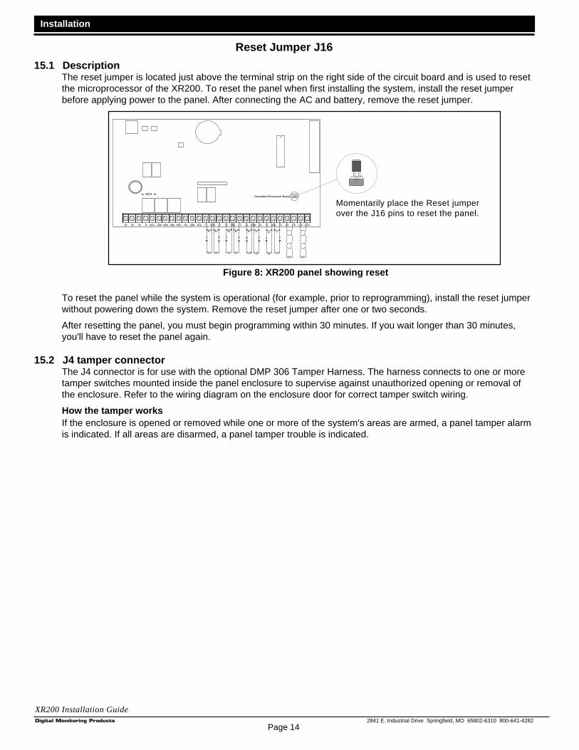
15.1 DescriptionThe reset jumper is located just above the terminal strip on the right side of the circuit board and is used to resetthe microprocessor of the XR200. To reset the panel when first installing the system, install the reset jumperbefore applying power to the panel. After connecting the AC and battery, remove the reset jumper.
To reset the panel while the system is operational (for example, prior to reprogramming), install the reset jumperwithout powering down the system. Remove the reset jumper after one or two seconds.
After resetting the panel, you must begin programming within 30 minutes. If you wait longer than 30 minutes,you'll have to reset the panel again.
15.2 J4 tamper connectorThe J4 connector is for use with the optional DMP 306 Tamper Harness. The harness connects to one or moretamper switches mounted inside the panel enclosure to supervise against unauthorized opening or removal ofthe enclosure. Refer to the wiring diagram on the enclosure door for correct tamper switch wiring.
How the tamper worksIf the enclosure is opened or removed while one or more of the system's areas are armed, a panel tamper alarmis indicated. If all areas are disarmed, a panel tamper trouble is indicated.
Momentarily place the Reset jumperover the J16 pins to reset the panel.
Figure 8: XR200 panel showing reset
J16Command Processor Reset
AC1 2 3 4 5 6 7 8 10 11 12 13 14 15 16 17 18 19
AC +B -B BELL GND SMK GND9
RED YEL GRN BLK20 21 22 23 24 25 26 27 28
L1 L2GND GND GND GNDL3 L4 L5 L6 L7 L8 L9- L9+ L10- L10+
Page 15
Installation
2841 E. Industrial Drive Springfield, MO 65802-6310 800-641-4282
XR200 Installation Guide
UNIVERSAL UL BURGLARY SPECIFICATIONS
16.1 IntroductionThe programming and installation specifications contained in this section must be completed when installing theXR200 panel in accordance with any of the UL burglary standards. Additional specifications may be required bya particular standard.
16.2 WiringAll wiring must be in accordance with NEC, ANSI/NFPA 70, UL 681, and UL 611 for all burglary installations.
16.3 Control outside of protected areaA Potter EVD or Sentrol 5402 should be used in place of a lined cabinet when the panel is installed outside ofthe protected area.
16.4 Police station phone numbersThe digital dialer telephone number programmed for communication must not be a police station phone number,unless that phone number is specifically provided for that purpose.
16.5 Bypass reportsThe Bypass Reports option must be programmed as YES for all UL burglary applications. See section 6.4 of theXR200 Programming Guide (LT-0196).
16.6 System maintenanceProper installation and regular maintenance by the installing alarm company and frequent testing by the enduser is essential to ensure continuous satisfactory operation of any alarm system. Offering a maintenanceprogram and acquainting the user with the correct procedure for use and testing of the system is also theresponsibility of the installing alarm company.
16.7 PartitionsThe partition option may only be used for UL burglary applications when all partitions are used for onesubscriber. See section 4.2 and 11.2 of the XR200 Programming Guide (LT-0196). The panel must be tamperprotected and Sentrol Model 5402 or Potter EVD listed vibration detectors should be used.
16.8 UL Listed ReceiversUL has verified operation with the DMP SCS-1, Sur-Gard SG-HLR2-DG, FBII CP220PB, Osborne-HoffmanQuick-Alert, and Radionics D6500 receivers.
UL 1023 SPECIFICATIONSHousehold Burglar-Alarm System Units
17.1 Bell cutoffThe Bell Cutoff time cannot be less than five minutes. See section 8.2 of the XR200 Programming Guide(LT-0196).
17.2 Entry delayThe maximum entry delay used must not be more than 45 seconds. See section 7.3 of the XR200 ProgrammingGuide (LT-0196).
17.3 Exit delayThe maximum exit delay used must not be more than 60 seconds. See section 12.4 of the XR200 ProgrammingGuide (LT-0196).
17.4 Weekly testThe product should be tested weekly.
Page 16
Installation
2841 E. Industrial Drive Springfield, MO 65802-6310 800-641-4282
XR200 Installation Guide
UL 1610 AND 1076 SPECIFICATIONSCentral-Station and Proprietary Burglar-Alarm Units
18.1 Multiplex network capacityThe total number of panels assigned to a standard MPX or DNET receiving line of the SCS-1 Receiver Systemmust not exceed 90. This may be increased to 180 by setting the SNRM option to NO in the SCS-1 Receiversystem. This is to allow any signal from a XR200 Command Processor to be transmitted to the receiver within 90seconds. This allows Grade AA Multiplex service.
18.2 Opening/Closing reportsThe Opening/Closing Reports option must be programmed as YES. See section 12.6 of the XR200Programming Guide (LT-0196).
18.3 Closing waitThe Closing Wait option must be programmed YES. See section 7.2 of the XR200 Programming Guide (LT-0196).
18.4 Proprietary dialerThe Model XR200 provides Grade A proprietary service when configured as a digital dialer.
18.5 AA Network CommunicationWhen HST communication is used, a dialer line must also be used along with the Model 893 Dual Phone LineModule to supervise the dialer line. The HST Check-in time must be set from 01 to 06 minutes or AA. This providesAA Central Station Service. See sections 3.2, 3.2.1, and 3.3 of the XR200 Programming Guide (LT-0196).
UL 1635 SPECIFICATIONSDigital Burglar Alarm Communicator System Units
19.1 System trouble displayThe Status List Display must include at least one keypad that displays system monitor troubles. See section 10.1of the XR200 Programming Guide (LT-0196).
19.2 Digital Dialer telephone numberBoth programmed telephone numbers must begin with a D or P. See sections 3.17 and 3.18 of the XR200Programming Guide (LT-0196).
19.3 Entry delayThe maximum entry delay used must not be more than 60 seconds. See section 7.3 of the XR200 ProgrammingGuide (LT-0196).
19.4 Exit delayThe maximum exit delay used must not be more than 60 seconds. See section 12.4 of the XR200 ProgrammingGuide (LT-0196).
19.5 Test timeThe Test Time option must be programmed so that the XR200 sends a report once every 24 hours. See sections3.8 to 3.10 of the XR200 Programming Guide (LT-0196).
19.6 Closing waitThe Closing Wait option must be programmed YES. See section 7.2 of the XR200 Programming Guide (LT-0196).
19.7 Grade B Central StationGrade B Central Station service can be provided under UL 1635 by adding a Grade A local audible signalappliance and placing the Model XR200 panel into the Model 349A Grade A Attack Resistant Housing.

Page 17
Installation
2841 E. Industrial Drive Springfield, MO 65802-6310 800-641-4282
XR200 Installation Guide
UL 365 AND 609 SPECIFICATIONSPolice Station Connected and Local Burglar Alarm Units and Systems
20.1 System trouble displayThe Status List Display must include at least one keypad that displays system monitor troubles. See section 10.3of the XR200 Programming Guide (LT-0196).
20.2 Entry delayThe maximum entry delay used must not be more than 60 seconds when using the Model 349A Grade Ahousing. See section 7.3 of the XR200 Programing Guide (LT-0196).
20.3 Grade A bellA Grade A local audible signal appliance must be used.
20.4 Bell cutoffThe Bell Cutoff time cannot be less than 15 minutes. See section 8.2 of the XR200 Programming Guide (LT-0196).
20.5 Automatic bell testThe Automatic Bell Test option must be programmed as YES. See section 8.3 of the XR200 Programming Guide(LT-0196).
20.6 Grade A MercantileFor Grade A Mercantile and Police Station Connect operation the Model XR200 must be mounted in a Grade AAttack Resistant Housing, (DMP Model 349A).
20.7 Mercantile Safe and VaultWhen the DMP Model 349A housing is used, the XR200 provides operation as a mercantile safe and vaultalarm. Bell Supervision and wiring must be in accordance with UL 681. If the Model XR200 is mounted outsidethe safe or vault, tamper protection and the Sentrol Model 5402 or Potter EVD listed vibration detectors shouldbe used.
20.8 Line security for Police ConnectBasic line security is provided when the Model XR200 is configured as a dialer system.
20.9 Bank Safe and VaultIn addition to the requirements for Mercantile Safe and Vault in section 20.7, the following must be done for BankSafe and Vault systems. The Bank Safe and Vault option must be programmed as YES. See section 12.19 of theXR200 Programming Guide (LT-0196). The 72 hour battery standby must be provided. A Rothenbuhler Model 5110High Security Bell must be used. See section 25.8 of the XR200 Installation Guide (LT-0197).
20.10 High Line SecurityHigh Line Security is provided when configured as a MPX, DNET, or HST system. When HST communication isused, a dialer line must also be used along with the Model 893 Dual Phone Line Module to supervise the dialerline. The HST Check-in time must be set from 01 to 06 minutes or AA. See sections 3.2, 3.2.1, and 3.3 of theXR200 Programming Guide (LT-0196).

Page 18
Installation
2841 E. Industrial Drive Springfield, MO 65802-6310 800-641-4282
XR200 Installation Guide
UNIVERSAL UL and NFPA FIRE ALARM SPECIFICATIONS
21.1 IntroductionThe programming and installation specifications contained in this section must be completed when installing theModel XR200 in accordance with any of the UL or NFPA fire standards. Additional specifications may be requiredby a particular standard.
21.2 WiringAll wiring must be in accordance with NEC, ANSI/NFPA 70.
21.3 TransformerA wire-in transformer should be used. Use the 16.5 VAC 40VA DMP Model 320. The transformer must bemounted within 20 feet of the panel connected by conduit.
21.4 End of Line resistorThe DMP Model 310 1K Ω EOL resistor should be used on all 1K Ω EOL fire zones.
21.5 System trouble displayThe Status List Display must include at least one keypad that displays system monitor troubles. See section 10.3of the XR200 Programming Guide (LT-0196).
21.6 Fire displayThe Status List Display must include at least one keypad that displays troubles and alarms on fire type zones.See section 10.4 of the XR200 Programming Guide (LT-0196).
21.7 Police station phone numberThe digital dialer telephone number programmed for communication must not be a police station phone number,unless that phone number is specifically provided for that purpose.
21.8 System maintenanceProper installation and regular maintenance by the installing alarm company and frequent testing by the end useris essential to ensure continuous satisfactory operation of any alarm system. Offering a maintenance programand acquainting the user with the correct procedure for use and testing of the system is also the responsibility ofthe installing alarm company.
21.9 Audible alarmFire Type zones should be programmed to activate an audible alarm. The Bell Action for Fire Type zones shouldnot be programmed as “N”. See section 8.4A in the XR200 Programming Guide (LT-0196).
21.10 Fire zone programmingIf a retard delay is used on a waterflow zone, it cannot exceed 90 seconds and any retard delay in the waterflowinitiating devices must be subtracted from the 90 seconds allowed. See sections 13.4 and 13.17 in the XR200Programming Guide (LT-0196). The retard delay should not be used on a zone with smoke detectors.
21.11 Style D zonesIf required, the Radionics D129 Dual Style D Initiating Module provides for connection of two Style D zones to theModel XR200. See section 26.4 and the D129 Installation Instructions for wiring information.
21.12 Video OptionThe Video option must be selected as NO when any fire protection is connected to the XR200. See section 7.9 inthe XR200 Programming Guide (LT-0196).
21.13 UL Listed ReceiversUL has verified operation with the DMP SCS-1 (SDLC), Sur-Gard SG-HLR2-DG (CID, M2E), FBII CP220PB(CID), Osborne-Hoffman Quick-Alert (CID, M2E), and Radionics D6500 (M2E) receivers.

Page 19
Installation
2841 E. Industrial Drive Springfield, MO 65802-6310 800-641-4282
XR200 Installation Guide
UL 985 NFPA 72 (Chapter 2) SPECIFICATIONSHousehold Fire Warning System Units
22.1 Bell output definitionThe Bell Output of the Model XR200 must be programmed to operate steady on burglary alarms and pulsed ortemporal on fire alarms. See sections 8.4A and 8.4B of the XR200 Programming Guide (LT-0196).
UL 864 NFPA 72 (Chapter 9) SPECIFICATIONSControl Units for Fire-Protective Signaling Systems
23.1 Zone restoral reportsThe Restoral Reports option must be selected as YES or DISARM. See section 6.3 in the XR200 ProgrammingGuide (LT-0196).
23.2 Power fail delayThe Power Fail Delay option must be selected as 6 hours. See section 7.6 of the XR200 Programming Guide(LT-0196).
23.3 Sprinkler supervisoryAny zone used for sprinkler supervisory must be programmed with "SPRINKLR XXX" as the zone name. Thelast three characters in the zone name may be assigned a number to identify the zone. The Model 893 DualPhone Line Module must be used on all sprinkler supervisory systems.
23.4 DACT systemsTwo phone lines must be used. The two phone lines cannot be ground start or party lines. The 893 Dual PhoneLine Module is used to provide connection of two phone lines to the system. The 2ND Phone Linecommunication option must be selected as YES. See section 3.3 of the XR200 Programming Guide (LT-0196).
Two different phone numbers must be programmed for digital communication. See sections 3.17 and 3.18 of theXR200 Programming Guide (LT-0196). The Test Time option must be programmed so that the XR200 sends areport every 24 hours. See sections 3.8 to 3.10 of the XR200 Programming Guide (LT-0196).
Additionally, you can use the 462N Network Interface Card and the HST (Host) Communication type for ancillarycommunication over digital data networks.
23.5 Type 2 and Type 3 Central Station ServiceType 2 and Type 3 Central Station Service can be provided by using MPX communication to the DMP SCS-1Receiver system. See section 3.2 of the XR200 Programming Guide (LT-0196).
23.6 Type 1 Central Station ServiceType 1 Central Station Service can be provided by using MPX as the main communication and digital dialer asbackup. The 893 Dual Phone Line Module is used to provide connection of the MPX and dialer lines. Seesection 3.2 of the XR200 Programming Guide (LT-0196). If Type 1 Central Station service is provided, the TestTime option must be programmed to send a report every 24 hours. See sections 3.8 to 3.10 of the XR200Programming Guide (LT-0196).
With both Type 1 and Type 2 Central Station service, the total number of panels assigned to a standard MPXreceiving line of the SCS-1 Receiver System must not exceed 90. This may be increased to 180 by setting theSNRM option to NO in the SCS-1 Receiver system. This is to allow any signal from a XR200 to be transmitted tothe receiver within 90 seconds.
Page 20
Installation
2841 E. Industrial Drive Springfield, MO 65802-6310 800-641-4282
XR200 Installation Guide
23.7 Local Protective Signaling SystemsThe DMP Model 865, 866, or 867 Notification Circuit Module must be used on the bell circuit for detection ofshorts and grounds. See sections 25.1 to 25.3 for wiring diagrams. Any burglary or other off premisescommunication must be done with the Model 893 Dual Phone Line Module.
23.8 Proprietary Protective Signaling SystemsThe total number of panels assigned to one MPX or DNET receiving line of the DMP SCS-1 Receiver systemmust not exceed 90. This may be increased to 180 by setting the SNRM option to NO in the SCS-1 Receiversystem. This is to allow any report from a XR200 to be sent to the receiver within 90 seconds.
23.9 Remote Station Protective Signaling SystemsYou must provide 60 hours of standby battery. Up to four 12 VDC, 6.5Ah batteries may be used. See section 6.6for standby battery calculations. Two Radionics Model D127 Reversing Relay Modules provide two reversingpolarity telephone connections. See section 25.5 and the D127 Installation Instruction sheet for wiring details. ADMP Model 893 is used to provide two line dialer communication or Type 1 Multiplex communication.
CALIFORNIA STATE FIRE MARSHAL SPECIFICATIONS
24.1 Bell output definitionThe Bell Output of the XR200 panel must be programmed to operate steady on burglary alarms and pulsed,temporal, or California School Code on fire alarms. See sections 8.4A and 8.4B of the XR200 ProgrammingGuide (LT-0196).

Page 21
Installation
2841 E. Industrial Drive Springfield, MO 65802-6310 800-641-4282
XR200 Installation Guide
25.1 Indicating circuit module installation
AU
XIL
IAR
Y P
OW
ER
SU
PP
LY
24 V
DC
5 A
mp
M
axim
um P
ower
Sup
ply
Trou
ble
Con
tact
s
N/C
NO
TE
: If a
n au
xilia
ry s
uppl
y is
not
use
d,te
rmin
als
3 an
d 4
on th
e 86
6 In
dica
ting
Circ
uit M
odul
e ca
n be
jum
pere
d to
geth
erto
sup
ply
bell
pow
er fr
om th
e X
R20
0 pa
nel.
A m
axim
um o
f 1.5
Am
ps a
t 12
VD
C is
avai
labl
e fr
om te
rmin
al 5
of t
he X
R20
0.
Aux
iliar
y po
wer
sup
ply
mus
t be
regu
late
dU
L lis
ted
for
Fire
Pro
tect
ion
Sig
nalin
g S
ervi
ce.
Pow
er s
uppl
ies
mus
t hav
e ba
ttery
bac
kup.
Eac
h 86
6 In
dica
ting
Circ
uit M
odul
ein
ala
rm d
raw
s up
to 3
5mA
from
its
term
inal
3 a
larm
inpu
t.
J4
J16
Com
man
d P
roce
ssor
Res
et
K4
J11
J12
DD
, MP
XS
elec
tion
AC1
23
45
67
810
1112
1314
1516
1718
19
AC
+B-B
BE
LLG
ND
SM
KG
ND
9
RE
DY
EL
GR
NB
LK20
2122
2324
2526
2728
L1L2
GN
DG
ND
GN
DG
ND
L3L4
L5L6
L7L8
L9-
L9+
L10-
L10+
Ans
wer
ing
Mac
hine
Byp
ass
Rel
ayU
se M
odel
305
K2
Pho
ne J
ack
Con
nect
or
J3
Lith
ium
Bat
tery
K7
K6
Rel
ay O
utpu
t 1U
se M
odel
305
Rel
ay O
utpu
t 2U
se M
odel
305
J6
J2
The
Aux
iliar
y P
ower
Sup
ply
and
Indi
catin
g C
ircui
t Mod
ule
trou
ble
cont
act z
one
mus
t be
prog
ram
med
as
a S
uper
viso
ryTy
pe z
one
and
mus
t be
sele
cted
for
disp
lay
in th
e ke
ypad
stat
us li
st.
See
sec
tion
10.6
in th
e X
R20
0 P
rogr
amm
ing
Gui
de (
LT-0
196)
.
= S
uper
vise
d C
ircui
tS
SS
SS
1 2 3 4 5 6 7 8
Aux
iliar
y P
ower
Gro
und
Ala
rm In
put
Bel
l Pow
er +
Inpu
t
Bel
l Pow
er –
Inpu
t
Bel
l A +
Out
put -
Bel
l A –
Out
put
Bel
l B +
Out
put
Bel
l Tro
uble
Bel
l Tro
uble
Bel
l B –
Out
put
9 10 11
UL
List
ed, P
olar
ized
Indi
catin
g D
evic
es.
Sty
le Z
Not
ifica
tion
Circ
uit M
odul
e
D
MP
Mod
el 8
65
85m
A a
t 12
VD
C
AU
XIL
IAR
Y P
OW
ER
SU
PP
LY
Pow
er S
uppl
yTr
oubl
e C
onta
cts
N
/C
24 V
DC
5 A
mp
M
axim
um
S S
1 2 3 4 5 6 7 8
Aux
iliar
y P
ower
Gro
und
Ala
rm In
put
Bel
l Pow
er In
put
Bel
l Out
put +
Bel
l Out
put -
Bel
l Tro
uble
Bel
l Tro
uble
UL
List
ed, P
olar
ized
notif
icat
ion
Dev
ices
.
10k
Ω E
OL
Res
isto
r D
MP
Mod
el 3
08
Not
ifica
tion
Circ
uit M
odul
e
D
MP
Mod
el 8
66
37m
A a
t 12
VD
C
1k Ω
Opt
iona
l Mod
ule
inst
alla
tion
Eac
h 86
5 N
otifi
catio
n C
ircui
t Mod
ule
in a
larm
dra
ws
up to
85m
A fr
om it
ste
rmin
al 3
ala
rm in
put.
S S S S
S S SS S S
S
Sty
le W

Page 22
Installation
2841 E. Industrial Drive Springfield, MO 65802-6310 800-641-4282
XR200 Installation Guide
25.2 Multiple indicating circuit modules
AU
XIL
IAR
Y P
OW
ER
SU
PP
LY
24 V
DC
5 A
mp
M
axim
um P
ower
Sup
ply
Trou
ble
Con
tact
s
N/C
NO
TE
: If a
n au
xilia
ry s
uppl
y is
not
use
d,te
rmin
als
3 an
d 4
on th
e 86
6 In
dica
ting
Circ
uit M
odul
e ca
n be
jum
pere
d to
geth
erto
sup
ply
bell
pow
er fr
om th
e X
R20
0 pa
nel.
A m
axim
um o
f 1.5
Am
ps a
t 12
VD
C is
avai
labl
e fr
om te
rmin
al 5
of t
he X
R20
0.
Aux
iliar
y po
wer
sup
ply
mus
t be
regu
late
dU
L lis
ted
for
Fire
Pro
tect
ion
Sig
nalin
g S
ervi
ce.
Pow
er s
uppl
ies
mus
t hav
e ba
ttery
bac
kup.
Eac
h 86
6 In
dica
ting
Circ
uit M
odul
ein
ala
rm d
raw
s up
to 3
5mA
from
its
term
inal
3 a
larm
inpu
t.
J4
J16
Com
man
d P
roce
ssor
Res
et
K4
J11
J12
DD
, MP
XS
elec
tion
AC1
23
45
67
810
1112
1314
1516
1718
19
AC
+B-B
BE
LLG
ND
SM
KG
ND
9
RE
DY
EL
GR
NB
LK20
2122
2324
2526
2728
L1L2
GN
DG
ND
GN
DG
ND
L3L4
L5L6
L7L8
L9-
L9+
L10-
L10+
Ans
wer
ing
Mac
hine
Byp
ass
Rel
ayU
se M
odel
305
K2
Pho
ne J
ack
Con
nect
or
J3
Lith
ium
Bat
tery
K7
K6
Rel
ay O
utpu
t 1U
se M
odel
305
Rel
ay O
utpu
t 2U
se M
odel
305
J6
J2
The
Aux
iliar
y P
ower
Sup
ply
and
Indi
catin
g C
ircui
t Mod
ule
trou
ble
cont
act z
one
mus
t be
prog
ram
med
as
a S
uper
viso
ryTy
pe z
one
and
mus
t be
sele
cted
for
disp
lay
in th
e ke
ypad
stat
us li
st.
See
sec
tion
10.6
in th
e X
R20
0 P
rogr
amm
ing
Gui
de (
LT-0
196)
.
= S
uper
vise
d C
ircui
tS
SS
SS
1 2 3 4 5 6 7 8
Aux
iliar
y P
ower
Gro
und
Ala
rm In
put
Bel
l Pow
er +
Inpu
t
Bel
l Pow
er –
Inpu
t
Bel
l A +
Out
put -
Bel
l A –
Out
put
Bel
l B +
Out
put
Bel
l Tro
uble
Bel
l Tro
uble
Bel
l B –
Out
put
9 10 11
UL
List
ed, P
olar
ized
Indi
catin
g D
evic
es.
Sty
le Z
Not
ifica
tion
Circ
uit M
odul
e
D
MP
Mod
el 8
65
85m
A a
t 12
VD
C
AU
XIL
IAR
Y P
OW
ER
SU
PP
LY
Pow
er S
uppl
yTr
oubl
e C
onta
cts
N
/C
24 V
DC
5 A
mp
M
axim
um
S S
1 2 3 4 5 6 7 8
Aux
iliar
y P
ower
Gro
und
Ala
rm In
put
Bel
l Pow
er In
put
Bel
l Out
put +
Bel
l Out
put -
Bel
l Tro
uble
Bel
l Tro
uble
UL
List
ed, P
olar
ized
notif
icat
ion
Dev
ices
.
10k
Ω E
OL
Res
isto
r D
MP
Mod
el 3
08
Not
ifica
tion
Circ
uit M
odul
e
D
MP
Mod
el 8
66
37m
A a
t 12
VD
C
1k Ω
Eac
h 86
5 N
otifi
catio
n C
ircui
t Mod
ule
in a
larm
dra
ws
up to
85m
A fr
om it
ste
rmin
al 3
ala
rm in
put.
S S S S
S S SS S S
S
To a
dditi
onal
tw
enty
-thre
e 86
6 In
dica
ting
Cir
cuit
Mod
ules
. U
p to
a m
axim
um o
f t
wen
ty-f
ive
866
mod
ules
on
the
XR
200
pane
l. A
ll m
odul
es m
ust
be in
stal
led
in a
34
0FC
, 349
, or
350
encl
osur
eco
nnec
ted
by n
o m
ore
than
20
feet
of
cond
uit.
Sty
le W

Page 23
Installation
2841 E. Industrial Drive Springfield, MO 65802-6310 800-641-4282
XR200 Installation Guide
25.3 Multiple indicating circuit modules for zoned annunciation
1
2
3
4
5
6
7
8
Auxiliary Power
Ground
Alarm Input
Bell Power + Input
Bell Power – Input
Bell A + Output -
Bell A – Output
Bell B + Output
Bell Trouble
Bell Trouble
Bell B – Output 9
10
11
24 VDC 5 Amp Maximum
Power SupplyTrouble Contacts N/C
Zone 2 Indicating CircuitModule. DMP Model 865 85mA at 12 VDC
The Auxiliary Power Supply and IndicatingCircuit Module trouble contact zone mustbe programmed as a Supervisory Type zoneand must be selected for display in thekeypad status list.See section 10.6 in the XR200Programming Manual (LT-0196).
NOTE: If an auxiliary supply isnot used, terminals 3 and 4 on the866 Indicating Circuit Module can bejumpered together to supply bell powerfrom the XR200 panel.
A maximum of 1.5 Amps at 12 VDCis available from terminal 5 of the XR200.
Auxiliary power supplies must beregulated UL listed for Fire ProtectionSignaling Service. Power suppliesmust have battery backup.
1
2
3
4
5
6
7
8
Auxiliary Power
Ground
Alarm Input
Bell Power Input
Bell Output +
Bell Output -
Bell Trouble
Bell Trouble
UL Listed, PolarizedIndicating Devices.
Style Y
AUXILIARY POWER SUPPLY
AUXILIARY POWER SUPPLY
10k Ω EOL Resistor DMP Model 308
1
2
3
4
5
6
7
8
Auxiliary Power
Ground
Alarm Input
Bell Power Input
Bell Output +
Bell Output -
Bell Trouble
Bell Trouble
UL Listed, PolarizedIndicating Devices.
10k Ω EOL Resistor DMP Model 308
AUXILIARY POWER SUPPLY
24 VDC 5 Amp Maximum
24 VDC 5 Amp Maximum
You can have up to twenty-five 866Indicating Circuit Modules by usingthe relay outputs available on theXR200 panel.All modules must be installed withina 340FC, 349, or 350 enclosureconnected by no more than 20 feet ofconduit.
Zone 1 Indicating CircuitModule. DMP Model 866 37mA at 12 VDC
CommonIndicating Circuit Module DMP Model 866 37mA at 12 VDC
To additional Zone 1Indicating Circuit Modules.
To additional Zone 2indicating circuit modules.
Zone 1Output
Zone 2Output
Each 866 Indicating Circuit Module inalarm draws up to 35mA from itsterminal 3 alarm input.
Outputs 3 to 10 canswitch up to 50mAeach at 12 VDC. Thisis sufficient for one866 module perindicating zone 3 to 10.
Relay 1 N/OOrange
Relays 1 and 2Common
Gray
Relay 2 N/OOrange
Model 430Output Harness
1k Ω
J4
Battery Only Restart CR7J16Command Processor Reset
Output Header J2All outputs must be connectedto devices located within thesame room as the control panel.
K4
J11J12
Ground Start Relay Use Model 305
DD, MPXSelection
Tamper Header
AC1 2 3 4 5 6 7 8 10 11 12 13 14 15 16 17 18 19
AC +B -B BELL GND SMK GND9
RED YEL GRN BLK20 21 22 23 24 25 26 27 28
Z1 Z2GND GND GND GNDZ3 Z4 Z5 Z6 Z7 Z8 Z9- Z9+ Z10- Z10+
Answering MachineBypass RelayUse Model 305 K2
Phone Jack Connector
J3
Lithium Battery
K7K6
Relay Output 1Use Model 305
Relay Output 2Use Model 305
EP
RO
M S
ocke
t
J6 In
terf
ace
Con
nect
or
J6
J2
Style W
Style W
S
S
S
S
S
S
S
S
S
S
S S S SS
S S
= Supervised CircuitS

Page 24
Installation
2841 E. Industrial Drive Springfield, MO 65802-6310 800-641-4282
XR200 Installation Guide
25.4 Dual Style D Zone Module installation
EARTH GROUND
AUX POWER
ZONE B
ZONE A
B 1
B 2
B 2
B 1
A 2
A 1
A 2
A 1Zone A
Zone B
Dual Style D Initiating ModuleModel 869
12 VDC Supply25mA Standby Current
75mA Alarm Current
Heat detectors, manual pullstations, or any other UL listed
shorting device.Unlimited number of units.
J4
J16Command Processor Reset
K4
J11J12
DD, MPXSelection
Tamper Header
AC1 2 3 4 5 6 7 8 10 11 12 13 14 15 16 17 18 19
AC +B -B BELL GND SMK GND9
RED YEL GRN BLK20 21 22 23 24 25 26 27 28
Z1 Z2GND GND GND GNDZ3 Z4 Z5 Z6 Z7 Z8 Z9- Z9+ Z10- Z10+
K2
Phone Jack Connector
J3
Lithium Battery
K7K6
Relay Output 1Use Model 305
Relay Output 2Use Model 305
J6
J2
= Supervised CircuitS
S S S S
S
S
S
S
S
S
S
S

Page 25
Installation
2841 E. Industrial Drive Springfield, MO 65802-6310 800-641-4282
XR200 Installation Guide
25.5 Remote Station reversing relay connection
EARTH GROUND
+ Signal Voltage In
Alternate Alarm
Combo Alarm
GROUND
GROUND
- Signal Voltage In
- To Remote Receiver
+ To Remote Receiver
Auxiliary Power Input
EARTH GROUND
+ Signal Voltage In
Alternate Alarm
Combo Alarm
GROUND
GROUND
- Signal Voltage In
- To Remote Receiver
+ To Remote Receiver
Auxiliary Power Input
To Telephone Line
To Telephone Line
Reversing Relay ModuleRadionics Model D127
12 VDC Supply5mA Standby55mA Alarm
Reversing Relay ModuleRadionics Model D127
12 VDC Supply5mA Standby55mA Alarm
Up to 60 hours of battery standby timecan be supplied using three or four7.0Ah sealed lead acid batteries.
Four 7.0Ah batteries may be requiredbased on total current draw of all devicesconnected to the panel. See section 6.6.
To connect four batteries to the XR200Command Processor panel, use three
Model 318 Battery Harnesses.
Outputs 3 to 6supply up to50mA at 12 VDC.
Note: Output 3 must beprogrammed as a FireAlarm Output and Output4 must be programmedas a Fire Trouble Output.See Sections 8.5D and8.5E of the XR200Programming Manual(LT-0196).
Fire Trouble Output 4 - White/Yellow
Model 430Output Harness
Intended for connection to a polarity reversalcircuit of a Remote Station receiving unithaving compatible ratings.
All modules must be installed ina listed enclosure connected byno more than 20 feet of conduit.
J4
J16Command Processor Reset
K4
J11J12
DD, MPXSelection
Tamper Header
AC1 2 3 4 5 6 7 8 10 11 12 13 14 15 16 17 18 19
AC +B -B BELL GND SMK GND9
RED YEL GRN BLK20 21 22 23 24 25 26 27 28
Z1 Z2GND GND GND GNDZ3 Z4 Z5 Z6 Z7 Z8 Z9- Z9+ Z10- Z10+
Answering MachineBypass RelayUse Model 305 K2
Phone Jack Connector
J3
Lithium Battery
K7K6
Relay Output 1Use Model 305
Relay Output 2Use Model 305
J6
J2
Fire Alarm Output 3 - White/Orange
= Supervised CircuitS
S S S S
Output Header J2All outputs must be connectedto devices located within thesame room as the control panel.

Page 26
Installation
2841 E. Industrial D
rive Springfield, M
O 65802-6310 800-641-4282
XR
20
0 In
stalla
tion
Gu
ide
25.6S
upervised remote relay
1
2
3
4
5
6
7
8
Auxiliary Power
Ground
Alarm Input
Bell Power Input
Bell Output +
Bell Output -
Bell Trouble
Bell Trouble
DMP part #DI-0001 Rectifier(1N4001 diode) in series withinput from Model 866 terminal 6.
10k Ω EOL Resistor DMP Model 308
Indicating Circuit ModuleDMP Model 86637mA at 12 VDC
1k Ω
Normally Opencontacts will close
on alarm.
Normally Closedcontacts will open
on alarm.
DPDT RelayUse Model ASRB-1 from Advanced Signaling.
30mA coil operating current at 12 VDC.
Model 430Output Harness
Relay #1 N/O (Orange)
Remote DPDTRelay
SupervisedSilence switch
Wiring between the 866 module and theDPDT relay is supervised against opens,shorts, and grounds. Either of thesetrouble conditions cause the 866 module'sBell Trouble contacts to open.
The zone connected to the Bell Trouble contacts on the 866 IndicatingCircuit Module must be programmed as a Supervisory Type zone and
selected for display in the keypad status list.
The 866 module must be installed in thepanel enclosure or in a 340FC, 349, or 350
enclosure connected by conduit.
J4
J16Command Processor Reset
Output Header J2All outputs must be connectedto devices located within thesame room as the control panel.
K4
J11J12
DD, MPXSelection
Tamper Header
AC1 2 3 4 5 6 7 8 10 11 12 13 14 15 16 17 18 19
AC +B -B BELL GND SMK GND9
RED YEL GRN BLK20 21 22 23 24 25 26 27 28
Z1 Z2GND GND GND GNDZ3 Z4 Z5 Z6 Z7 Z8 Z9- Z9+ Z10- Z10+
Answering MachineBypass RelayUse Model 305 K2
Phone Jack Connector
J3
Lithium Battery
K7K6
Relay Output 1Use Model 305
Relay Output 2Use Model 305
J6
J2
Relay #1 Common (Gray)
= Supervised CircuitS
S S SS
S S

Page 27
Installation
2841 E. Industrial Drive Springfield, MO 65802-6310 800-641-4282
XR200 Installation Guide
25.7 Cellular backup installation for Derived Channel burglary
12
34
56
Pan
el A
uxili
ary
Pow
er -
Ter
min
al 7
Pan
el C
omm
on -
Ter
min
al 1
0
Sup
ervi
sory
Zon
e In
put -
Zon
e +
Gra
y -
Rel
ay #
1 C
omm
on
Ora
nge
- R
elay
#1
Nor
mal
ly O
pen
Gra
y -
Rel
ay #
2 C
omm
on
Ora
nge
- R
elay
#2
Nor
mal
ly O
pen
Not
e 1
Not
e 1
RJ3
1X T
elco
Jac
kD
CX
Sys
tem
s S
TU
-2Z
Not
e 1:
Use
EO
L Te
rmin
atio
n A
ssem
bly
P/N
210
24-0
001
(2.2
k 1/
2 W
Res
isto
r).
Mod
el 4
30O
utpu
t Har
ness
.
Use
EO
L Te
rmin
atio
nA
ssem
bly
P/N
210
24-0
003
(590
Ω 1
/2 W
Res
isto
r).
J4
Bat
tery
Onl
y R
esta
rt C
R7
J16
Com
man
d P
roce
ssor
Res
et
Out
put H
eade
r J2
All
outp
uts
mus
t be
conn
ecte
dto
dev
ices
loca
ted
with
in th
esa
me
room
as
the
cont
rol p
anel
.
K4
J11
J12
Gro
und
Sta
rt R
elay
Use
Mod
el 3
05
DD
, MP
XS
elec
tion
Tam
per
Hea
der
AC1
23
45
67
810
1112
1314
1516
1718
19
AC
+B-B
BE
LLG
ND
SM
KG
ND
9
RE
DY
EL
GR
NB
LK20
2122
2324
2526
2728
Z1
Z2
GN
DG
ND
GN
DG
ND
Z3
Z4
Z5
Z6
Z7
Z8
Z9-
Z9+
Z10
-Z
10+
Ans
wer
ing
Mac
hine
Byp
ass
Rel
ayU
se M
odel
305
K2
Pho
ne J
ack
Con
nect
or
J3
Lith
ium
Bat
tery
K7
K6
Rel
ay O
utpu
t 1U
se M
odel
305
Rel
ay O
utpu
t 2U
se M
odel
305
EPROM Socket
J6 Interface Connector
J6
J2
CE
LLU
LAR
TRAN
SCE
IVE
R
CE
LLU
LAR
DAT
AIN
TE
RFA
CE
AU
XIL
IAR
YP
OW
ER
SU
PP
LYCE
LLU
LAR
ANT
EN
NA
The
Sec
ure-
Com
™ C
ellu
lar
Sys
tem
mus
t be
conn
ecte
d to
a s
epar
ate
pow
ersu
pply
. Onl
y fo
r su
pple
men
tary
use
.
= S
uper
vise
d C
ircui
tS
SS
S
S S S S
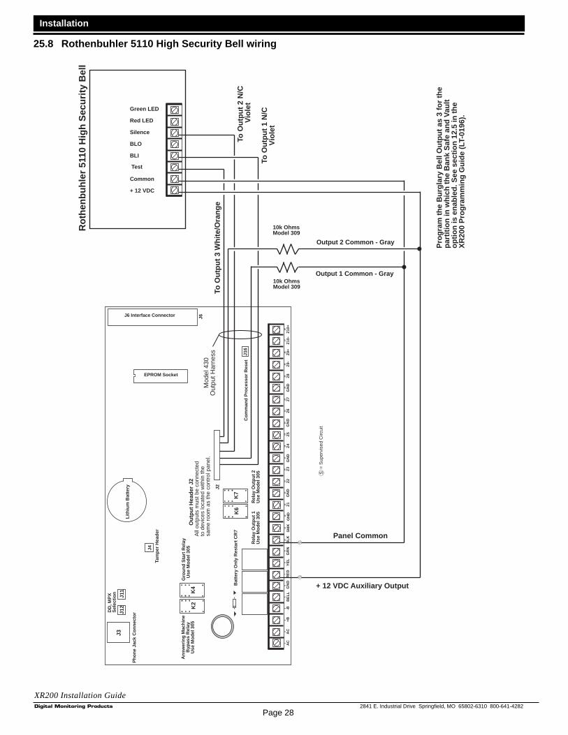
Page 28
Installation
2841 E. Industrial Drive Springfield, MO 65802-6310 800-641-4282
XR200 Installation Guide
J4
Bat
tery
Onl
y R
esta
rt C
R7
J16
Com
man
d P
roce
ssor
Res
et
Out
put H
eade
r J2
All
outp
uts
mus
t be
conn
ecte
dto
dev
ices
loca
ted
with
in th
esa
me
room
as
the
cont
rol p
anel
.
K4
J11
J12
Gro
und
Sta
rt R
elay
Use
Mod
el 3
05
DD
, MP
XS
elec
tion
Tam
per
Hea
der
AC1
23
45
67
810
1112
1314
1516
1718
19
AC
+B-B
BE
LLG
ND
SM
KG
ND
9
RE
DY
EL
GR
NB
LK20
2122
2324
2526
2728
Z1
Z2
GN
DG
ND
GN
DG
ND
Z3
Z4
Z5
Z6
Z7
Z8
Z9-
Z9+
Z10
-Z
10+
Ans
wer
ing
Mac
hine
Byp
ass
Rel
ayU
se M
odel
305
K2
Pho
ne J
ack
Con
nect
or
J3
Lith
ium
Bat
tery
K7
K6
Rel
ay O
utpu
t 1U
se M
odel
305
Rel
ay O
utpu
t 2U
se M
odel
305
EPROM Socket
J6 Interface Connector J6
J2
Output 2 Common - Gray
Output 1 Common - Gray
+ 12 VDC Auxiliary Output
Panel Common
10k OhmsModel 309
10k OhmsModel 309
To O
utpu
t 1 N
/CV
iole
t
To O
utpu
t 3 W
hite
/Ora
nge
To O
utpu
t 2 N
/CV
iole
t
Rot
henb
uhle
r 51
10 H
igh
Sec
urity
Bel
l
Pro
gram
the
Bur
glar
y B
ell O
utpu
t as
3 fo
r th
epa
rtiti
on in
whi
ch th
e B
ank
Saf
e an
d V
ault
optio
n is
ena
bled
. See
sec
tion
12.5
in th
eX
R20
0 P
rogr
amm
ing
Gui
de (
LT-0
196)
.
Green LED
Red LED
Silence
BLO
Common
+ 12 VDC
BLI
Test
Mod
el 4
30O
utpu
t Har
ness
= S
uper
vise
d C
ircui
tS
SS
25.8 Rothenbuhler 5110 High Security Bell wiring

Page 29
Installation
2841 E. Industrial Drive Springfield, MO 65802-6310 800-641-4282
XR200 Installation Guide
Each LX-Bus™ module mustbe selected with its ownindependent address from 00to 99. A Supervisory zonemust be programmed into theXR200 to properly superviseeach module.
= Supervised CircuitS
BlackGreenYellow
Red
Normal/Silence Switch
Bell Trouble LED
Data LED
Power SupplyMonitor LED
LX-Bus™ wiring
TENS ONES
TENS ONES
BELL RELAYADDRESS
SUPERVISORYADDRESS
1 Bell In +
2 Bell In -
3 Bell Out +
4 Bell Out -
5 Bell Trouble
6 Bell Trouble
7 PWR Mon.
8 Mon. RTN
+ -
Connect to panelSupervisory zone
10K EOL ResistorDMP Model # 308
12 or 24 VDC
12 or 24 VDC
UL Listed,PolarizedIndicatingDevices
Ground Fault LED
BELLPOWERSUPPLY
To additional LX-Bus modulesFrom panel
Bell Ring Style
Normally ClosedCommonNormally Open
Form C ContactsTypicalR
elay
1
Rel
ay 2
Rel
ay 3
Relay 4
Open CollectorAnnunciator Outputs
Optional LED wiring50mA at 50 VDC resistive
Graphic A nnunciator ModuleDMP Model 71710mA at 12 VDC
Output Expander ModuleDMP Model 7167mA at 12 VDC
LX-Bus Expansion CardDMP Models 462N, 462P, 472, or 481.
S
S
S
S
S
S
S
S
S
S
S
S
Optional LED wiring50mA at 50 VDC resistive
Notification Circuit ModuleDMP Model 867
25.9 LX-Bus™ Module Connection

Page 302841 E. Industrial Drive Springfield, MO 65802-6310 800-641-4282
XR200 Installation Guide
2841 E. Industrial Drive Springfield, MO 65802-6310 800-641-4282Digital Monitoring Products