xr200 command processor panel programming guide program manual.pdf · this programming guide...
TRANSCRIPT

Do Not Throw Away!This programming guide contains information you need to program andservice the XR200 panel and should be kept along with your other DMPtechnical documentation.
LT-0196 (9/97)
XR200 Command Processor PanelProgramming Guide
242 Zone Burglary/Fire/Access Control Panel with Built-in Communicator
2841 E. Industrial Drive Springfield, MO 65802-6310

ii
MODEL XR200 PROGRAMMING GUIDE
Also contains programminginstructions for use with the Model 485 Access Control Expansion card.
Copyright © 1995 - 1997 Digital Monitoring Products, Inc.
Information furnished by DMP is believed to be accurate and reliable.This information is subject to change without notice.
When using the Series XR200 panel for any UL, NFPA, CSFM, or other listingorganization's approved methods, refer to this manual and the XR200 Installation Guide(LT-0197). These documents outline the installation and programming requirements ofall applications for which the XR200 is approved.

iii
ContentsPage
Before you begin .................................................................................... 1
Getting Started ....................................................................................... 1
Programmer Operation .......................................................................... 1
Programmer Lockout Codes ................................................................. 2
Reset Timeout ........................................................................................ 2
Special Keys ........................................................................................... 2
Entering Alpha Characters .................................................................... 3
Entering Non-alpha Characters ............................................................ 3
Keypad Prompts Display Current Programming ................................ 3
InitializationCLEAR ALL CODES ................................................................................................................. 4
CLEAR ALL SCHEDULES ........................................................................................................ 4
CLEAR DISPLAY EVENTS MEMORY ...................................................................................... 4
CLEAR ZONE INFORMATION ................................................................................................. 4
CLEAR AREA INFORMATION .................................................................................................. 4
CLEAR OUTPUT INFORMATION ............................................................................................ 4
CLEAR COMMUNICATION AND REMOTE OPTIONS ............................................................ 4
SET TO FACTORY DEFAULTS ................................................................................................ 4
CommunicationCOMMUNICATION TYPE ......................................................................................................... 5
CHECK-IN TIME ....................................................................................................................... 6
2ND PHONE LINE .................................................................................................................... 6
TEST FREQUENCY ................................................................................................................. 7
ACCOUNT NUMBER ................................................................................................................ 7
TRANSMIT DELAY ................................................................................................................... 7
DTMF ........................................................................................................................................ 7
EVENTS MANAGER................................................................................................................. 7
DEFER TEST TIME .................................................................................................................. 8
TEST FREQUENCY ................................................................................................................. 8
TEST TIME ............................................................................................................................... 8
RECEIVER ONE PROGRAMMING .......................................................................................... 8
ALARM REPORTS ................................................................................................................... 8
SUPERVISORY/TROUBLE REPORTS .................................................................................... 8
OPENING/CLOSING AND USER REPORTS........................................................................... 8
TEST REPORT ......................................................................................................................... 8
BACKUP REPORTING ............................................................................................................. 8
FIRST TELEPHONE NUMBER ............................................................................................... 8
SECOND TELEPHONE NUMBER ........................................................................................... 9
RECEIVER TWO PROGRAMMING ......................................................................................... 9
PAGER TYPE ........................................................................................................................... 9
ALARM REPORTS ................................................................................................................... 9
SUPERVISORY/TROUBLE REPORTS .................................................................................... 9OPENING/CLOSING AND USER REPORTS........................................................................... 9
DOOR ACCESS ........................................................................................................................ 9
TEST REPORT ......................................................................................................................... 9
Section
iv
TABLE OF CONTENTS
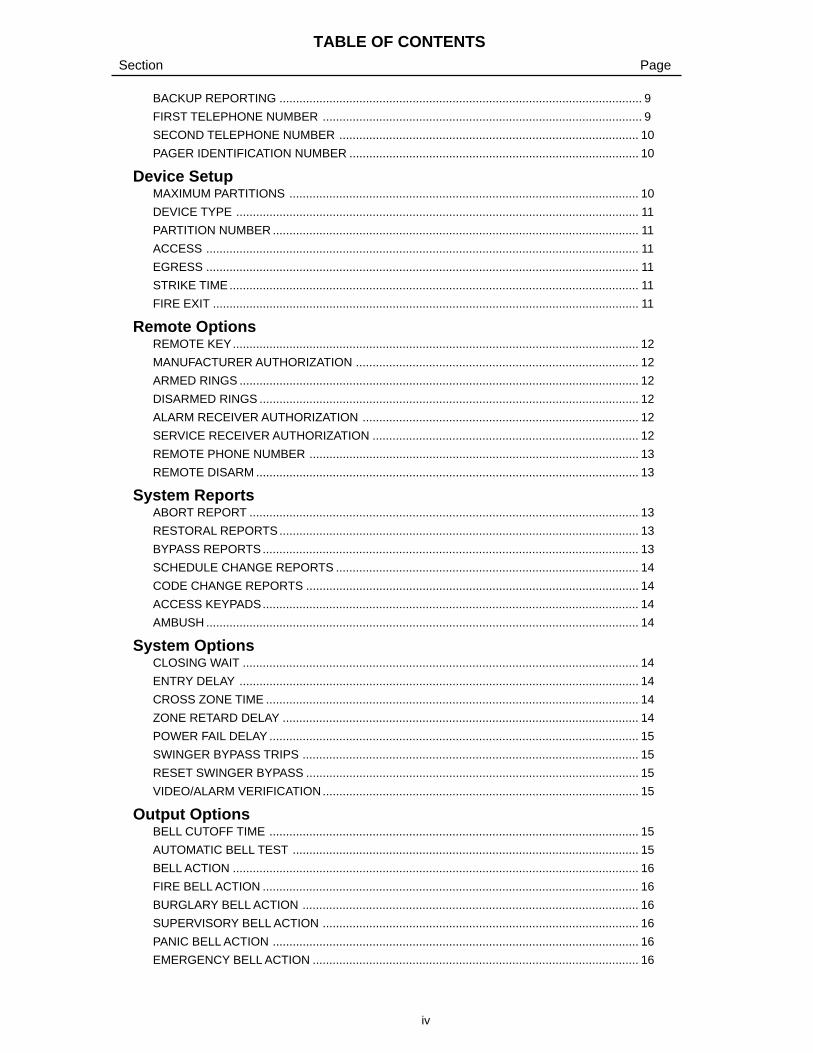
BACKUP REPORTING ............................................................................................................. 9
FIRST TELEPHONE NUMBER ................................................................................................ 9
SECOND TELEPHONE NUMBER .......................................................................................... 10
PAGER IDENTIFICATION NUMBER ....................................................................................... 10
Device SetupMAXIMUM PARTITIONS ......................................................................................................... 10
DEVICE TYPE ......................................................................................................................... 11
PARTITION NUMBER .............................................................................................................. 11
ACCESS .................................................................................................................................. 11
EGRESS .................................................................................................................................. 11
STRIKE TIME........................................................................................................................... 11
FIRE EXIT ................................................................................................................................ 11
Remote OptionsREMOTE KEY.......................................................................................................................... 12
MANUFACTURER AUTHORIZATION ..................................................................................... 12
ARMED RINGS ........................................................................................................................ 12
DISARMED RINGS .................................................................................................................. 12
ALARM RECEIVER AUTHORIZATION ................................................................................... 12
SERVICE RECEIVER AUTHORIZATION ................................................................................ 12
REMOTE PHONE NUMBER ................................................................................................... 13
REMOTE DISARM ................................................................................................................... 13
System ReportsABORT REPORT ..................................................................................................................... 13
RESTORAL REPORTS............................................................................................................ 13
BYPASS REPORTS................................................................................................................. 13
SCHEDULE CHANGE REPORTS ........................................................................................... 14
CODE CHANGE REPORTS .................................................................................................... 14
ACCESS KEYPADS................................................................................................................. 14
AMBUSH .................................................................................................................................. 14
System OptionsCLOSING WAIT ....................................................................................................................... 14
ENTRY DELAY ........................................................................................................................ 14
CROSS ZONE TIME ................................................................................................................ 14
ZONE RETARD DELAY ........................................................................................................... 14
POWER FAIL DELAY ............................................................................................................... 15
SWINGER BYPASS TRIPS ..................................................................................................... 15
RESET SWINGER BYPASS .................................................................................................... 15
VIDEO/ALARM VERIFICATION............................................................................................... 15
Output OptionsBELL CUTOFF TIME ............................................................................................................... 15
AUTOMATIC BELL TEST ........................................................................................................ 15
BELL ACTION .......................................................................................................................... 16
FIRE BELL ACTION ................................................................................................................. 16
BURGLARY BELL ACTION ..................................................................................................... 16
SUPERVISORY BELL ACTION ............................................................................................... 16
PANIC BELL ACTION .............................................................................................................. 16
EMERGENCY BELL ACTION .................................................................................................. 16
PageSection

v
TABLE OF CONTENTS
AUXILIARY 1 BELL ACTION ................................................................................................... 16
AUXILIARY 2 BELL ACTION ................................................................................................... 16
OUTPUT ACTION .................................................................................................................... 16
CUTOFF OUTPUT ................................................................................................................... 16
OUTPUT CUTOFF TIME ......................................................................................................... 16
COMMUNICATION FAILURE OUTPUT..................................................................................... 15
FIRE ALARM OUTPUT .............................................................................................................. 17
FIRE TROUBLE OUTPUT ......................................................................................................... 17
AMBUSH OUTPUT .................................................................................................................... 17
ENTRY OUTPUT ....................................................................................................................... 17
EXIT OUTPUT............................................................................................................................ 17
READY OUTPUT ....................................................................................................................... 17
PHONE TROUBLE OUTPUT ..................................................................................................... 17
LATE TO CLOSE OUTPUT ........................................................................................................ 17
DEVICE FAIL OUTPUT .............................................................................................................. 17
Menu DisplayARMED STATUS ........................................................................................................................ 18
TIME ........................................................................................................................................... 18
ARM/DISARM ............................................................................................................................ 18
Status ListDISPLAY KEYPADS ................................................................................................................... 18
SYSTEM MONITOR TROUBLES .............................................................................................. 18
FIRE ZONES .............................................................................................................................. 19
BURGLARY ZONES .................................................................................................................. 19
SUPERVISORY ZONES ............................................................................................................ 19
PANIC ZONES ........................................................................................................................... 19
EMERGENCY ZONES ............................................................................................................... 19
AUXILIARY 1 ZONES ................................................................................................................ 19
AUXILIARY 2 ZONES ................................................................................................................ 19
Printer ReportsARM AND DISARM REPORTS.................................................................................................. 20
ZONE REPORTS ....................................................................................................................... 20
USER COMMAND REPORTS ................................................................................................... 20
DOOR ACCESS REPORTS....................................................................................................... 20
SUPERVISORY REPORTS ....................................................................................................... 20
Area InformationPARTITION NUMBER ................................................................................................................ 20
ARMING MODE ......................................................................................................................... 20
EXIT DELAY .............................................................................................................................. 21
BURGLARY BELL OUTPUT ...................................................................................................... 21
OPENING/CLOSING REPORTS ............................................................................................... 21
CLOSING CHECK...................................................................................................................... 21
CLOSING CODE ........................................................................................................................ 21
ANY BYPASS ............................................................................................................................. 22
AREA SCHEDULES ................................................................................................................... 22
PRIMARY/SECONDARY SCHEDULES .................................................................................... 22
AREA NUMBER ......................................................................................................................... 22
PageSection

vi
TABLE OF CONTENTS
PageSection
AREA NAME .............................................................................................................................. 22
ACCOUNT NUMBER ................................................................................................................. 22
AUTOMATIC ARMING ............................................................................................................... 23
BAD ZONES............................................................................................................................... 23
AUTOMATIC DISARMING ......................................................................................................... 23
ARMED OUTPUT NUMBER ...................................................................................................... 23
BANK SAFE AND VAULT ........................................................................................................... 23
COMMON AREA ........................................................................................................................ 23
Zone InformationZONE NUMBER ......................................................................................................................... 24
ZONE NAME .............................................................................................................................. 24
ZONE TYPE ............................................................................................................................... 24
FIRE BELL OUTPUT.................................................................................................................. 25
PARTITION NUMBER ................................................................................................................ 25
AREA NUMBER ......................................................................................................................... 25
AREA ASSIGNMENT ................................................................................................................. 25
ARMING ZONE AREA ASSIGNMENT ....................................................................................... 25
NEXT ZONE ............................................................................................................................... 25
WIRELESS ................................................................................................................................. 26
CHECK IN TIME......................................................................................................................... 26
INTERNAL CONTACT................................................................................................................ 26
END OF LINE ............................................................................................................................. 26
NORMALLY OPEN ..................................................................................................................... 26
DISARMED OPEN ..................................................................................................................... 26
REPORT TO TRANSMIT ........................................................................................................... 26
OUTPUT NUMBER ................................................................................................................... 27
OUTPUT ACTION ...................................................................................................................... 27
SWINGER BYPASS ................................................................................................................... 27
FAST RESPONSE ..................................................................................................................... 28
CROSS ZONE............................................................................................................................ 28
PRIORITY .................................................................................................................................. 28
PROGRAM TRANSMITTER ...................................................................................................... 28
CONNECT TRANSMITTER ....................................................................................................... 28
CONNECT COMMAND TRANSMITTER ................................................................................... 28
PREWARN ADDRESSES .......................................................................................................... 29
ENTRY DELAY ........................................................................................................................... 29
ZONE RETARD .......................................................................................................................... 29
PRESIGNAL ADDRESSES ........................................................................................................ 29
STOP.......................................................................................................................................... 30
SET LOCKOUT CODE ............................................................................................................... 30
AppendixEvents Manager ................................................................................................................. ....... 31
Zone Type Description .......................................................................................................... ... 32
Diagnostics Function ........................................................................................................... .... 33
Using the 984 Command Function ......................................................................................... 33
690 Series Keypads Speaker Operation ................................................................................ 33
Cross Zoning ................................................................................................................... ......... 33
Zone Type Specifications ....................................................................................................... . 34

12841 E. Industrial Drive Springfield, MO 65802-6310 800-641-4282
XR200 Programming Guide
1.1 Before you begin
About this guideThis guide provides programming information for the DMP XR200 Command Processor™ Panel. After thisIntroduction, the remaining sections describe the functions of each programming menu item along with the availableoptions. Before starting to program, we recommend you read through the contents of this guide. The informationcontained here allows you to quickly learn the programming options and operational capabilities of the XR200 panel.
In addition to this guide, you should also read and be familiar with the following XR200 documents:
• XR200 Installation Guide (LT-0197)
• XR200 Product Specification (LT-0198)
• XR200 Security Command® User's Guide (LT-0287)
Internal ProgrammerThe XR200 contains all of its programming information in an on-board processor and does not require an externalprogrammer. You can perform all programming tasks through a DMP alphanumeric keypad set to address one.
Programming Information SheetIncluded with each XR200 panel are the Programming Information Sheets. These list the various programmingprompts and available options for programming the panel. Before starting to program, we recommend you completelyfill out each sheet with the programming options you intend to enter into the panel.
Having completed programming sheets available while entering data helps prevent errors and can shorten the timeyou spend programming. Completed sheets also provide you with an accurate record of the panel's program you cankeep on file for future system service or expansion. The remainder of this Introduction provides instructions forstarting and ending a XR200 programming session using the alphanumeric keypad.
1.2 Getting StartedBefore starting to program the XR200 panel, make sure the panel is properly grounded and AC and battery power isapplied to the appropriate panel terminals. All wiring connections and grounding instructions are detailed in theXR200 Installation Guide (LT-0197).
Accessing the Programmer
1. Install the reset jumper across the two J16 reset pinsfor two seconds. See Figure 1.
2. Remove the reset jumper and place it over just onepin for future use.
3. Enter the code 6653 (PROG) into an alphanumerickeypad set to address one. Press COMMAND.
4. The keypad displays: PROGRAMMER.
You are now ready to start programming the XR200 panel.Pressing the COMMAND key scrolls you through theprogramming functions listed in section 1.3. Each of these functions are described in detail in sections 2 to 15.
Initializing the PanelAfter installing the XR200, use the Initialization function to set to defaults the panel's programming. Note: Thedefault user code is 99. This should be changed by the owner as soon as the system is operational.
1.3 Programmer OperationThere are 14 programming sections to choose from:
Menu Item Section Menu Item SectionInitialization 2 Menu Display 9Communication 3 Status List 10Device Setup 4 Printer Reports 11Remote Options 5 Area Information 12System Reports 6 Zone Information 13System Options 7 Stop 14
Output Options 8 Set Lockout Code 15
1 - INTRODUCTION
Figure 1: Installing the reset jumper on J16
J16J16Command Processor Reset
AC1 2 3 4 5 6 7 8 10 11 12 13 14 15 16 17 18 19
AC +B -B BELL GND SMK GND9
RED YEL GRN BLK20 21 22 23 24 25 26 27 28
L1 L2GND GND GND GNDL3 L4 L5 L6 L7 L8 L9- L9+ L10- L10+

2
XR200 Programming Guide2841 E. Industrial Drive Springfield, MO 65802-6310 800-641-4282
1 - INTRODUCTION
1.3 Programmer Operation continuedTo select a section for programming, press any one of the top row SELECT keys when the name of that section isdisplayed on the keypad. The detailed instructions for each programming step are found in sections 2 to 15.
1.4 Programmer Lockout CodesThe XR200 panel allows you to enter the programming function without entering a code using the steps 1 to 4 listedin section 1.2. We recommend, however, that you install a Lockout Code that restricts programming to only thosepersons your company authorizes. You can do this by using the SET LOCKOUT CODE feature in the Programmer.
Use this new Lockout Code to restrict any unauthorized programming of the panel.
Installing a Lockout CodeAfter resetting the panel and entering the code 6653, the keypad displays PROGRAMMER. Press COMMAND toadvance through the programming sections until SET LOCKOUT CODE is displayed (after STOP). Press any top rowSELECT key. The keypad displays ENTER CODE: – . Enter a 3 to 5 digit Programmer Lockout Code and pressCOMMAND. The keypad displays ENTER AGAIN followed by ENTER CODE: –. Enter the same 3 to 5 digit code asecond time and press COMMAND. The keypad displays CODE CHANGED.
Note: The XR200 panel will not accept a 5-digit Lockout Code higher than 65535.
The new code number must now be entered before the programmer function can be accessed.
The Lockout Code should be written down and kept in a secure place with access limited to only those personsauthorized by your company to program the panel.
Lost Lockout Code requires factory reset: If you lose or forget the Lockout Code, the panel must be sent back tothe factory to be reset. There is no field option for gaining access to the panel without a valid access code.
1.5 Reset TimeoutThe XR200 has a feature that requires you to enter the Programmer within 30 minutes of resetting the panel. After 30minutes, if you attempt to program by entering the 6653 (PROG) code, the keypad displays: RESET PANEL . Youmust reset the panel and enter the program code within the next 30 minutes.
If you are already in the Programmer and do not press any keys on the programming keypad for 30 minutes, thepanel terminates programming. All data entered up to that time is saved in the panel's memory.
1.6 Special Keys
COMMAND KeyThe COMMAND key allows you to go forward through theprogramming menu and through each step of a programmingsection. As you go through the programming, the keypaddisplay shows any current programming already stored in thepanel's memory. If the information is not to be changed,press the COMMAND key to advance to the next step.
The COMMAND key is also used to enter information into thepanel's memory such as phone numbers or zone names. Pressthe COMMAND key after you've entered the information and it'sbeing displayed correctly on the keypad.
ARROW KeyUse the ARROW key to back up one step while programming.The ARROW key is also used when an error is made while entering information. Press the ARROW key once toerase the last character entered.
SELECT KeysThe top row of keys are called the SELECT keys. Each time a SELECT key is to be used, the keypad displays thefunction or options above the key. Displaying choices above the individual SELECT keys allows them to be used formany different applications. For example, you can enter AM or PM when programming the automatic test time oranswer YES or NO for a system option.
1 2 3 4
5 6 7 8
9 0 COMMAND
A B C DEF GHI JKL
VWXSTUPQRMNO
YZ
POWER
ARROW Key
SELECT Keys
Figure 2: Keypad Function keys
COMMAND Key

32841 E. Industrial Drive Springfield, MO 65802-6310 800-641-4282
XR200 Programming Guide
1 - INTRODUCTION
During programming, the SELECT keys also allow you to change information currently in the panel's memory bypressing the appropriate SELECT key under the display then entering the new information through the keypad.
When there are more than four response options available, pressing the COMMAND key brings up the next 1 to 4options on the keypad display. Pressing the ARROW key allows you to review the previous four choices.
The SELECT keys are also used for selecting a section from the programming menu by pressing any one of theSELECT keys when the name of the programming section you want is displayed.
1.7 Entering Alpha CharactersSome options during programming require you to enter alpha characters. To enter an alpha character, press the keythat has that letter written below it. The keypad displays the number digit of the key. Next, press the SELECT key thatcorresponds to the location of the letter under the key. Pressing a different SELECT key changes the letter. Whenanother digit key is pressed, the last letter displayed is retained and the process is started over.
1.8 Entering non-Alpha CharactersTo enter a space in an alpha entry, press the 9 digit key followed by the third SELECT key. The three characters onthe 9 digit key are Y, Z, and space. You can also enter the following characters: – (dash), . (period), * (asterisk), and #(pound sign) using the zero key and the four SELECT keys from left to right. For example, to enter a – (dash), pressthe zero key and then the left SELECT key. A dash now appears in the keypad display.
1.9 Keypad Prompts Display Current ProgrammingEach programming prompt displayed at the keypad shows the currently selected option in the panel's memory. Theseoptions are either shown as a number, a blank, or a NO or YES. To change a number or blank to a new number,press any top row SELECT key. The current option is replaced with a dash. Press the number(s) on the keypad youwant to enter as the new number for that prompt.
It is not necessary to enter numbers with leading zeros. The XR200 automatically right justifies the number when youpress the COMMAND key.
To change a programming prompt that requires a NO or YES response, press the top row SELECT key under theresponse not selected.
For example, if the current prompt is selected as YES and you want to change it to NO, press the third top rowSELECT key. The display changes to NO. Press the COMMAND key to go to the next prompt. See Figure 4.
BELL TST YES
Press the top row select key.
BELL TST NO
The keypad display changes to the newlyselected option. Press COMMAND.
NEXT
Figure 4: Changing the current option selected.
Figure 3: Keypad display and top row keys
Center CharacterLeft Character Right Character
S Y S T E M O N

4
XR200 Programming Guide2841 E. Industrial Drive Springfield, MO 65802-6310 800-641-4282
2 - INITIALIZATION
2.1 INITIALIZATIONThis function allows you to clear selected parts of the panel's program back to the factorydefaults in preparation for system programming.
A description of each selection follows:
2.2 CLEAR ALL CODESNO - Leaves existing codes intact.
YES - Clears the user code memory and assigns the user code number 99 to the highestuser position in each partition.
2.3 CLEAR ALL SCHEDULESNO - Leaves existing schedules intact.
YES - Clears all primary, secondary, permanent, temporary, and output schedules.
2.4 CLEAR DISPLAY EVENTS MEMORYNO - Leaves existing event memory intact.
YES - Clears the Security Command keypad display events memory.
2.5 CLEAR ZONE INFORMATIONNO - Leaves existing zone information intact.
YES - Clears the zone information for all zones. All zones are marked * UNUSED * and mustbe renamed before being able to display on any system keypad.
2.6 CLEAR AREA INFORMATIONNO - Leaves existing area information intact.
YES - Clears the area information for all areas. All areas are marked * UNUSED * and mustbe renamed before being able to display on any system keypad.
2.7 CLEAR OUTPUT INFORMATIONNO - Leaves existing output information intact.
YES - Clears all programmed Output names and any output cutoff assignment.
2.8 CLEAR COMMUNICATION AND REMOTE OPTIONSNO - Leaves existing communication and remote options intact.
YES - Clears the communication and remote options programming to factory defaults.
2.9 SET TO FACTORY DEFAULTSNO - Leaves existing panel programming intact.
YES - Sets the remainder of the panel's programming back to the factory default selections.
INITIALIZATION
CODES? NO YES
SURE? YES NO
SCHDS? NO YES
SURE? YES NO
EVENTS? NO YES
SURE? YES NO
ZONES? NO YES
SURE? YES NO
AREAS? NO YES
SURE? YES NO
COM/RMT? NO YES
SURE? YES NO
DEFAULTS NO YES
SURE? YES NO
OUTPUTS? NO YES
SURE? YES NO
CODES? NO YES
SURE? YES NO
SCHEDS? NO YES
For each initialization section, theProgrammer provides a NO or YES option.
Selecting NO advances you to the nextsection prompt and does not initializethat section of the program..
Selecting YES advances you to aconfirmation prompt.
If you select YES, the panel initializes that section of theprogram and advances you to the next section prompt.
If you select NO, the panel advances you to the next sectionprompt but does not initialize that section of the program.

52841 E. Industrial Drive Springfield, MO 65802-6310 800-641-4282
XR200 Programming Guide
3.1 COMMUNICATIONThis section of programming allows you to configure the communication options for theXR200 panel. The information you'll program varies with the Communication Type you select.
3.2 COMMUNICATION TYPESpecifies the communication method the panel uses to report system events to DMP SCS-1Receivers or non-DMP receivers. Press any SELECT key.
NONE - For local systems. Selecting this ends communication programming.
DD - Digital Dialer communication to a DMP SCS-1 Receiver.
MPX - Multiplex communication to a DMP SCS-1 Receiver.
M2E - Modem IIe communication to non-DMP receivers. This format sends the report codesof the Radionics Modem IIe communication format to the receiver(s) programmed in Receiver1 and 2 programming. Once the receiver has been contacted, the XR200 waits approximately45 seconds for the Modem IIe handshake beofore hanging up and making another attempt.
DNET - Data network connection to a DMP SCS-1 Receiver following multiplex rules. Thisoption requires the use of the 462N Network Interface Card. You can also use the backupdialer capability of the XR200 by selecting the option 2ND LINE as YES. See section 3.3.
CID - This option allows the panel to communicate to non-DMP receivers using the AdemcoContact ID format. When selected, the panel sends all of its alarm, trouble, and supervisoryreports to the receiver(s) programmed in Receiver 1 and 2 Programming.
When CID is selected, the panel sends reports to the receiver using either CID or standardDMP SDLC based on each receiver's ability to process the CID format. The panel determineswhether the receiver can process the CID format by the acknowledgment tones the receivertransmits when first contacted.
If the receiver can process the CID format, only those event reports for which there are CIDdefinitions will be sent by the panel. This restriction prevents the panel from dialing thereceiver for a report it cannot send.
HST (Host) - Asynchronous communication using the 462N Network Interface Card. TheDMP Host/Output reporting format is transmitted over an asynchronous computer or radionetwork to the SCS-1 Receiver. All zone alarms and restorals transmitted on the HostChannel are also duplicated on the 2ND LINE (section 3.3) if it is selected.
Note: When HST is selected as the Communication Type, 2ND LINE programming (section3.3) allows you to select D2 for two line supervision when using a Model 893 or 893A DualPhone Line Module.
After selecting HST, the keypad displays MODEM SETUP:. Press COMMAND. Enter up to15 characters for the dial string that is sent to the device connected to the 462N NetworkInterface Card. When a report is to be sent, the panel first sends "+++ATHc
r (carriage return)",
waits one second then sends the dial string characters entered in MODEM SETUP. This isfollowed with a space and a " c
r." The modem must respond to the panel with "CONNECTc
r".
If no response is received from the modem after 60 seconds, the cycle is repeated. Any stringother than "CONNECTc
r" that is returned by the modem and ends with a " c
r" is considered a
NAK. A NAK response causes the entire output to repeat after a 4-second delay.
If "CONNECTcr" is properly received from the modem the standard HST report/response
sequences occur. After a report is sent and acknowledged, or sent five times and notacknowledged five times, the panel sends "+++ATHc
r" to the modem.
If the Host channel fails to receive a proper acknowledgment after five attempts, the panelsends a WARNING: NETWORK TROUBLE (S72) report on the 2ND LINE. The next time areport is sent by the panel over the Host channel, the panel sends a NETWORK RESTORED(S73) report over the 2ND LINE.
Note: You can use HST along with a 462N Network Interface Card to provide upload/download capability using the DMP Remote Access™ software program.
COMM TYPE: NONE
3 - COMMUNICATION
COMMUNICATION
NONE DD MPX M2E
DNET C I D HST
MODEM SETUP:
–

6
XR200 Programming Guide2841 E. Industrial Drive Springfield, MO 65802-6310 800-641-4282
3.2.1 CHECK-IN TIMEEnter two digits (00 to 60) to specify the time delay in minutes the panel uses to send thenext Check-in report. This prompt is only displayed if HST is selected in section 3.2. SinceHST is not a polled communication method, the Check-in time allows the SCS-1 Receiver toget a Check-in report (s070) periodically to verify continuous communication with the panel.SCS-1/805 firmware is required in the SCS-1 Receiver. Zero causes the Check-in report tonot be sent. Press any SELECT key for AA reporting. Press COMMAND to continue.
Selecting AA instead of entering a Check-in time causes the panel to send the Check-inreport at random times. When all areas are disarmed, the report is sent randomly but alwayswithin 60 minutes. If any area is armed, the report is sent every six minutes. The SCS-1Receiver verifies that the next Check-in report is received at the appropriate time. SCS-1/805firmware is required in the SCS-1 Receiver. If the Check-in fails, the panel sends aWARNING: NETWORK TROUBLE (S72) report on the 2ND LINE. The next time the reportis sent, the panel sends a NETWORK RESTORED (S73) report over the 2ND LINE.
3.3 2ND PHONE LINEAllows you to use a second communication line to send reports to the SCS-1 Receivershould the first phone line fail. If 2ND LINE is DD or CELL (and you're not using a 462NNetwork Interface Card), you'll need to install a DMP 893 or 893A Dual Phone Line Module toconnect both the main and secondary phone lines to the panel.
Both DD and MPX type systems can be backed up with a dialer or cellular line. Multiplexlines cannot be used as a secondary line.
NONE - A second line is not used.
DD - Dialer communication to a DMP SCS-1 Receiver. When using M2E as the mainCommunication Type, you cannot use DD on the 2ND LINE.
CELL - Cellular communication with Cell-Miser™ restrictions. When Cell-Miser is selected,the following call restrictions apply to the panel.
1. Only zone alarms, Ambush, Line 1 Trouble, Abort, Recall Test, and Delayed Eventsare sent over the cellular system. Delayed Events are only sent if the cellular call wasmade for one of the other allowed reports.
2. Line 1 Trouble is sent only once during each armed period.
3. The dialing sequence uses the first phone number on line 1 only and the second phonenumber on line 2 only. This allows the panel to use the cellular phone number forcellular calls only without needing prefixes or area codes for land line dialing.
If 2ND LINE = DD If 2ND LINE = CELL
Panel dials the 1st ph # twice on Line 1 Panel dials the 1st ph # twice on Line 1
Panel dials the 1st ph # twice on Line 2 Panel dials the 2nd ph # twice on Line 2
Panel dials the 2nd ph # twice on Line 1 Panel dials the 1st ph # twice on Line 1
Panel dials the 2nd ph # twice on Line 2 Panel dials the 2nd ph # twice on Line 2
Panel dials the 1st ph # twice on Line 1 Panel dials the 1st ph # twice on Line 1
D2 - Select D2 to allow supervision of a second telephone line connected to a Model 893 or893A Dual Phone Line Module. D2 is only displayed if HST is the main Communication type.
HST (HOST) - DMP Asynchronous communication to a DMP SCS-1 Receiver or Hostautomation system. If HST is selected as the Communication Type in section 3.2, HST willnot be displayed as an option in 2ND LINE. If HST is selected for 2ND LINE, all zone alarmsand restorals are duplicated on the asynchronous channel in addition to the maincommunication method. HST is not displayed if DNET is the main Communication type.
When HST is used as the main or 2ND LINE communication method, the account numbermust not begin with a number that matches a line number being used for multiplex service onthe same SCS-1 Receiver. This allows the Redisplay Non-Restored status list to workproperly in receivers with SCS1/805 or higher firmware.
3 - COMMUNICATION
NONE DD CELL HST
2ND LINE: NONE
CHECKIN:
CHECKIN: – AA
NONE DD CELL D2
NONE DD CELL

72841 E. Industrial Drive Springfield, MO 65802-6310 800-641-4282
XR200 Programming Guide
3.3.1 TEST FREQUENCY
Specifies the communication test interval for the second phone line. This is displayed if 2NDLINE is programmed as DD, CELL or HST.
NONE - No communication test is made on the second line.
REG - A 2ND LINE communication test is made each time the regular communication test iscompleted.
7 - A communication test is made every 7 days at the test time programmed for the regularcommunication test. Test time deferrals are disregarded.
30 - A communication test is made every 30 days at the test time programmed for the regularcommunication test. Test time deferrals are disregarded.
If the 2ND LINE test fails to communicate after 10 attempts, the regular communication channel sends a WARNING:PANEL BACKUP COMMUNICATION FAIL (S12) report. The next time the panel sends a report over the 2ND LINE,the regular communication channel sends a BACKUP COMMUNICATION LINE RESTORED (S04) report.
3.4 ACCOUNT NUMBEREnter the account number sent to the SCS-1 Receiver.
DD and HST - The range of valid account numbers for a panel using these CommunicationTypes is 1 to 65,535. For accounts of four digits or less, do not enter leading zeros. Thepanel automatically right justifies the account number.
CID and M2E - Choose an account number between 1 to 9999.
MPX and DNET - A 5-digit account number is required for panelsusing these formats. The first digit is the receiver line number. Thesecond digit is always zero. The last three digits are the panel'saccount number. This number must be between the range of 000and 127. Individual area account numbers must be between therange of 128 to 999 on the same line. Example: 10128 to 10999.
3.5 TRANSMIT DELAYEnter the length of time the panel waits before sending burglary reports to the receiver. Theavailable range is 1 to 60 seconds. Alarm bells and relay outputs are not delayed during thisperiod. Burglary Outputs in section 8 must be programmed for pulsed or steady. Set AbortReports in section 6 to YES if Opening and Closing reports are not being sent.
Enter zero to disable Transmit Delay.
3.6 DTMFYES enables tone dialing by the panel. NO enables rotary dialing.
3.7 EVENTS MANAGERSpecifies when non-alarm reports are sent to the receiver. This selection does not affectzone alarm, zone trouble, zone restoral, supervisory, or serviceman messages. Closingreports are not delayed if the Closing Wait option is YES. See Section 7.2.
SND - If send is selected, all reports are sent to the receiver as they occur.
DLY - All non-alarm reports are held until the panel's memory buffer contains 133 events oruntil the panel's next communication with the receiver. The Model 485 Access Control cardwill hold Door Access granted reports until the panel's memory buffer contains 665 events oruntil the panel's next communication with the receiver. Contact ID and Modem IIe do notdelay reports but send them as they occur.
KEEP - All non-alarm reports are held in the panel's memory buffer until they're over writtenby new activity. You can view the contents of the memory buffer using the DMP RemoteAccess™ software or the display events feature in the User Menu. Refer to the Appendix fora table listing the delayed report types.
3 - COMMUNICATION
EVENT MGR: SEND
DTMF YES
SND DLY KEEP
ACCT NO: 1 2 3 4 5
XMIT DELAY: 0
NONE REG 7 30
TEST FREQ: NONE
10 0 01
R'cvr #
Always zero
Acct. #

8
XR200 Programming Guide2841 E. Industrial Drive Springfield, MO 65802-6310 800-641-4282
3.8 DEFER TEST TIMESelect YES to allow the programmed test report to be deferred if the panel communicateswith a receiver within the time set in Test Frequency. See section 3.9. Select NO to send thetest report as programmed regardless of previous panel communication.
3.9 TEST FREQUENCYAllows you to set how often the panel's test report is sent to the SCS-1 receiver. Enter from 1to 60 days. This prompt is not displayed if Defer Test Time is set to NO.
3.10 TEST TIMEPress COMMAND to show the enter test time display. Enter the time of day the panel sendsthe test report to the SCS-1 Receiver. Use entries between 12:00 to 11:59 and then chooseAM or PM. When Defer Test Time is set to NO, this option allows you to program the day ofthe week the test report is sent. Choose one day of the week or all days.
3.11 RECEIVER ONE PROGRAMMINGAllows you to set the options for the first receiver the XR200 panel attempts to contact whensending reports. The panel supports communication to two receivers.
3.12 ALARM REPORTSYES sends Abort, Alarm, Alarm Restoral, Ambush, Exit Error, and System Recently Armedreports to this receiver.
3.13 SUPERVISORY/TROUBLE REPORTSYES sends Supervisory, Trouble, Trouble Restoral, Force Armed, Zone Fault reports, andServiceman Messages to this receiver. If the Model 485 is used Access Denied Reports willalso be sent.
3.14 OPENING/CLOSING AND USER REPORTSYES sends Opening, Closing, Door Access, Late to Close, Unauthorized Entry, Scheduleand Code changes, Zone Reset, and Zone Bypass reports by user to this receiver.
3.15 TEST REPORTEnter YES to enable the system test report to be sent to this receiver. Reports are sentaccording to the programming in sections 3.9 to 3.10.
3.16 DOOR ACCESS REPORTSYES sends Door Access Granted reports to this receiver whenever a door access is grantedto a user. The Door Access Granted report is only sent if the keypad number has also beenselected in Access Keypads under the SYSTEM REPORTS programming. This prompt onlyappears when a Model 485 Access Control card is installed.
3.17 BACKUP REPORTINGEnter YES to enable this receiver to be a backup to the other receiver in the event the otherreceiver cannot be contacted.
3.18 FIRST TELEPHONE NUMBERThis is the first number the panel dials when sending reports to this receiver. Phone numberscan be up to 15 characters in length. You can program a three second pause in the dialingsequence by entering the letter P. You can program a dial tone detect by entering the letterD. These characters are counted as part of the 15 allowable characters.
Area code selection for cellular communication: You can also enter a letter "C" in the first or second phonenumber. When entered, the characters before the "C" are only used when a 2nd LINE Cellular call is being made. Allother calls made on the main phone line will only use the characters entered after the letter "C". The letter "C" isnever dialed and is recognized by the panel as a marker only.
3 - COMMUNICATION
SPV/TRBL YES
O/C USER YES
BACKUP NO
FIRST PHONE NO.
TEST RPT YES
ALARM YES
RECEIVER 1 PROG
TEST FREQ: 0
TEST TIME
0 : 0 0 A M PM
TEST DAY: ALL
DFR TEST NO
–
DOOR ACS NO

92841 E. Industrial Drive Springfield, MO 65802-6310 800-641-4282
XR200 Programming Guide
3.19 SECOND TELEPHONE NUMBERThe panel dials the second number when two successive tries using the first number havefailed. If the panel cannot reach the receiver after two attempts using the second number, itreturns to the first number and makes two additional attempts. A total of ten dialing attemptsare made using the first and second phone numbers.
Each number can be up to 15 characters in length including any P or D characters enteredfor pause and dial tone detect.
Should all ten attempts fail, the panel clears the communication buffer and makes onecommunication attempt each hour to send a TRANSMIT FAILED (S87) report to the receiver.The report information that was not sent to the receiver is available from the Display Eventsfeature of the User Menu and can be downloaded with DMP Remote Access™ software.
3.20 RECEIVER TWO PROGRAMMINGAllows you to set the options for the second receiver the XR200 panel attempts to contactwhen sending reports. If you select YES for any of the second receiver options, you musthave at least one phone number programmed in Receiver 2 programming.
3.21 PAGER TYPEThis option allows the panel to send Alarm, Trouble, Opening, Closing, and Late to Closereports to a customer's numeric or alphanumeric pager. The panel uses DTMF tones fornumeric pagers and Glenayre protocol for alphanumeric pagers to generate the account andreport information sent over the pager terminal equipment. Selecting NONE allows you to usethe Receiver 2 Programming to send panel reports to a second receiver.
NONE - The pager reporting option is not being used.
NUMERIC - Reports are sent to the customer's numeric only pager.
ALPHANUMERIC - Reports are sent to the customer's alphanumeric pager.
3.22 ALARM REPORTSSee section 3.12.
3.23 SUPERVISORY/TROUBLE REPORTSSee section 3.13
3.24 OPENING/CLOSING AND USER REPORTSSee section 3.14.
3.25 TEST REPORTSee section 3.15.
3.26 DOOR ACCESS REPORTSSee Section 3.16
3.27 BACKUP REPORTINGSee section 3.17.
3.28 FIRST TELEPHONE NUMBEREnter the phone number the panel will dial to send reports to the receiver or pager. Phonenumbers can be 15 characters in length. You can program a three second pause in thedialing sequence by entering the letter P. You can program a dial tone detect by entering theletter D. These characters are counted as part of the 15 allowable characters.
3 - COMMUNICATION
O/C USER YES
SPV/TRBL YES
ALARM YES
PAGER? NONE
NONE NUM ALPHA
BACKUP NO
TEST RPT YES
RECEIVER 2 PROG
–
SECOND PHONE NO.
–
FIRST PHONE NO.
DOOR ACS NO

10
XR200 Programming Guide2841 E. Industrial Drive Springfield, MO 65802-6310 800-641-4282
3.29 SECOND TELEPHONE NUMBERWhen PAGER? is NONE. The panel dials the second number when two successive triesusing the first number have failed. If the panel cannot reach the receiver after two attemptsusing the second number, it returns to the first number and makes two additional attempts. Atotal of ten dialing attempts are made using the first and second phone numbers.
Each number can be up to 15 characters in length including any P or D characters enteredfor pause and dial tone detect.
3.30 PAGER IDENTIFICATION NUMBEREnter a pager identification number if your pager uses one. If it does, the panel waits for nineseconds after having dialed the First Phone Number before sending the Pager ID. After thePager ID has been transmitted, the panel waits another three seconds before sending theactual pager message containing the panel reports. You can program additional three secondpauses by entering a letter P for each pause you want to add.
4.1 DEVICE SETUPThis section allows you to define the physical configuration of the XR200 panel. Enter thenumber of partitions in the system and the types of devices installed at each address alongwith their assigned partition. You can install and address up to eight supervised devices onthe keypad data bus, sixteen if the Model 485 Access Control Expansion card is used. Onlythe first eight may be keypads or zone expanders. Any address may be a Model 733Weigand Interface Module. No zones are available from addresses 9 - 16.
A description of each option follows:
4.2 MAXIMUM PARTITIONSMaximum number of partitions you want in this system. You can choose from 1 to 4. Tochange the number displayed, press any SELECT key, enter the number of partitions youwant to enable, and press COMMAND.
Changing the number of partitions resets user codes: Whenever you change the number of partitions on theXR200, all programmed user codes are cleared. The only user code available after a partition change is the factorydefault of 99.
Figure 5: Areas and user codes available with partitioning
MAX PARTITION: 1
DEVICE SETUP
3 - COMMUNICATION
PAGER ID NUMBER
–
SECOND PHONE NO
–
PartitionsEnabled
Areas Available User CodesAvailable
XR200
User CodesAvailable
XR200-485
1 1 to 8 1 to 200 1 to 999
2 Partition 1 - 1 to 8
Partition 2 - 1 to 4
Partition 1 - up to 100
Partition 2 - up to 100
Partition 1 - up to 500
Partition 2 - up to 500
3 Partition 1 - 1 to 8
Partition 2 - 1 to 4
Partition 3 - 1 to 4
Partition 1 - up to 50
Partition 2 - up to 50
Partition 3 - up to 50
Partition 1 - up to 400
Partition 2 - up to 300
Partition 3 - up to 300
4 Partition 1 - 1 to 8
Partition 2 - 1 to 4
Partition 3 - 1 to 4
Partition 4 - 1 to 4
Partition 1 - up to 50
Partition 2 - up to 50
Partition 3 - up to 50
Partition 4 - up to 50
Partition 1 - up to 400
Partition 2 - up to 200
Partition 3 - up to 200
Partition 4 - up to 200
4 - DEVICE SETUP
112841 E. Industrial Drive Springfield, MO 65802-6310 800-641-4282
XR200 Programming Guide
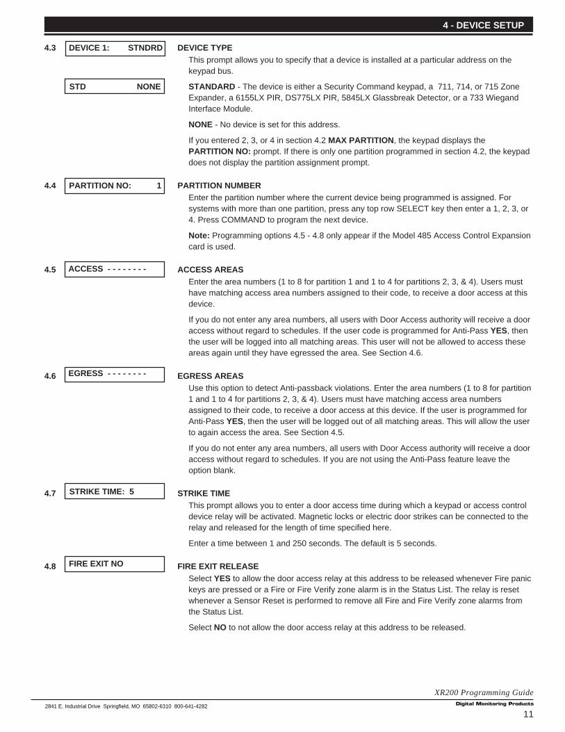
4.3 DEVICE TYPEThis prompt allows you to specify that a device is installed at a particular address on thekeypad bus.
STANDARD - The device is either a Security Command keypad, a 711, 714, or 715 ZoneExpander, a 6155LX PIR, DS775LX PIR, 5845LX Glassbreak Detector, or a 733 WiegandInterface Module.
NONE - No device is set for this address.
If you entered 2, 3, or 4 in section 4.2 MAX PARTITION , the keypad displays thePARTITION NO: prompt. If there is only one partition programmed in section 4.2, the keypaddoes not display the partition assignment prompt.
4.4 PARTITION NUMBEREnter the partition number where the current device being programmed is assigned. Forsystems with more than one partition, press any top row SELECT key then enter a 1, 2, 3, or4. Press COMMAND to program the next device.
Note: Programming options 4.5 - 4.8 only appear if the Model 485 Access Control Expansioncard is used.
4.5 ACCESS AREASEnter the area numbers (1 to 8 for partition 1 and 1 to 4 for partitions 2, 3, & 4). Users musthave matching access area numbers assigned to their code, to receive a door access at thisdevice.
If you do not enter any area numbers, all users with Door Access authority will receive a dooraccess without regard to schedules. If the user code is programmed for Anti-Pass YES, thenthe user will be logged into all matching areas. This user will not be allowed to access theseareas again until they have egressed the area. See Section 4.6.
4.6 EGRESS AREASUse this option to detect Anti-passback violations. Enter the area numbers (1 to 8 for partition1 and 1 to 4 for partitions 2, 3, & 4). Users must have matching access area numbersassigned to their code, to receive a door access at this device. If the user is programmed forAnti-Pass YES, then the user will be logged out of all matching areas. This will allow the userto again access the area. See Section 4.5.
If you do not enter any area numbers, all users with Door Access authority will receive a dooraccess without regard to schedules. If you are not using the Anti-Pass feature leave theoption blank.
4.7 STRIKE TIMEThis prompt allows you to enter a door access time during which a keypad or access controldevice relay will be activated. Magnetic locks or electric door strikes can be connected to therelay and released for the length of time specified here.
Enter a time between 1 and 250 seconds. The default is 5 seconds.
4.8 FIRE EXIT RELEASESelect YES to allow the door access relay at this address to be released whenever Fire panickeys are pressed or a Fire or Fire Verify zone alarm is in the Status List. The relay is resetwhenever a Sensor Reset is performed to remove all Fire and Fire Verify zone alarms fromthe Status List.
Select NO to not allow the door access relay at this address to be released.
4 - DEVICE SETUP
DEVICE 1: STNDRD
STD NONE
PARTITION NO: 1
ACCESS - - - - - - - -
EGRESS - - - - - - - -
STRIKE TIME: 5
FIRE EXIT NO

12
XR200 Programming Guide2841 E. Industrial Drive Springfield, MO 65802-6310 800-641-4282
5.1 REMOTE OPTIONSThis section allows you to enter the information needed for Remote Command/RemoteProgramming operation. A description of the Remote Options follow:
5.2 REMOTE KEYThis option allows you to enter a code of up to eight digits for use in verifying the authority ofan alarm or service receiver to perform a remote command/programming session. TheRemote Access™ program must give the correct key to the panel before being allowed anyremote functions. All panels are shipped from the factory with the key preset as blank.
To enter a remote key or change the current one, press a top row SELECT key and enter anycombination of up to eight digits. Press COMMAND. The current key is never displayed.
5.3 MANUFACTURER AUTHORIZATIONSelect YES to allow DMP Technical Support technicians to access the panel during systemservice or troubleshooting. This authorization automatically expires within one hour.
DMP remote service is provided on a read only basis: DMP technicians can look at the system programming andmake suggestions only. Alterations can only be accomplished by the installing company's service personnel.
5.4 ARMED RINGSEnter the number of rings the panel counts before answering the phone line when all areas ofthe system are armed. Any number from 1 to 15 can be entered. If zero is entered, the paneldoes not answer the phone when all areas of the system are armed.
5.5 DISARMED RINGSEnter the number of rings the panel counts before answering the phone line while any areasof the system are disarmed. Any number from 1 to 15 can be entered. If zero is entered, thepanel does not answer the phone when any area of the system is disarmed.
5.6 ALARM RECEIVER AUTHORIZATIONSelect YES to enable remote commands and programming to be accepted from the alarmSCS-1 Receiver. The Remote Key option can also be required.
With YES selected, the panel requests the receiver key during its first communication withthe first SCS-1 receiver. The panel retains this alarm receiver key in memory and allowsremote commands to be accepted from the alarm receiver. If an alarm occurs during aremote connect, the alarm report is immediately sent to this receiver only.
When NO is selected, remote commands and programming are not accepted from the alarmSCS-1 Receiver.
5.7 SERVICE RECEIVER AUTHORIZATIONYES enables remote commands and programming to be accepted from a secondary servicereceiver other than the alarm SCS-1 Receiver. The Remote Key option can also be required.
With YES selected, the panel requests the service receiver key the first time it's contactedby the service receiver. The panel retains this service receiver key in memory and acceptsremote commands from the service receiver.
If an alarm occurs during a remote connect, the panel disconnects from the service receiverand calls the alarm receiver. Alarm reports are only sent to the alarm receiver. It is importantthat the alarm receiver key and the service receiver key programmed at the central stationare NOT the same so the panel can determine the difference between receivers.
When NO is selected remote commands and programming are not accepted from asecondary service receiver.
This option must be YES to allow programming from a directly connected computer or anEther-Com.
5 - REMOTE OPTIONS
REMOTE OPTIONS
RMT KEY:
MFG AUTH NO
ARM RINGS: 0
DISARM RINGS: 0
ALR RCVR NO
SVC RCVR YES

132841 E. Industrial Drive Springfield, MO 65802-6310 800-641-4282
XR200 Programming Guide
5.8 REMOTE PHONE NUMBERPress COMMAND to enter the phone number the panel dials whenever remote programmingis requested. After entering a phone number, the panel allows remote commands andprogramming only after it has first been called by the authorized receiver, disconnected itself,and has redialed the remote phone number.
Note: When the function 984 + COMMAND is entered at the keypad, a remote options menuappears. This menu contains the following options:
NUMBER - The panel allows you to enter into the keypad a phone number you want thepanel to dial. Enter any required prefixes and area codes.
REMOTE - The panel dials the phone number programmed in Remote Phone Number. Seesection 5.8.
PICKUP - The panel picks up the phone line as Remote Access™ calls in. The phone mustbe ringing before selecting PICKUP. If a Remote Phone Number is NOT entered, and AlarmReceiver and Service Receiver is YES the panel allows remote commands and programmingwithout disconnecting and redialing. The phone number can be up to 15 digits in length. Entera D for dial tone detect and a P for a 3 second pause.
5.9 REMOTE DISARMYES allows the panel to be disarmed remotely. NO disables remote disarming.
6.1 SYSTEM REPORTSThis section allows you to select specific system reports the XR200 sends to the receiver.
6.2 ABORT REPORTYES allows the panel to send an alarm abort report to the receiver any time an area isdisarmed after an alarm report has been sent and the Bell Cutoff Time has not expired. Noalarmed zones can still be armed. A Warning: Alarm Bell Silenced report is also sent if thealarm bell is silenced by a user.
Abort reports are also sent when the system is disarmed during Transmit Delay and the BellOutput Timer is active. See section 3.5.
6.3 RESTORAL REPORTSThis option allows you to control when and if a zone restoral report is sent to the centralstation receiver. Press a top row SELECT key to display the following options:
NO - Disables the zone restoral report option. Zones continue to operate normally but do notsend restoral reports to the receiver.
YES - Enables the zone restoral report option. Zone restorals are sent whenever a zonerestores from a trouble or alarm condition.
DISARM - This option causes the panel to send non-24 hour zone restoral reports whenevera zone that has restored from a trouble or alarm condition is disarmed. All 24 hour zonessend restoral reports as they restore.
6.4 BYPASS REPORTSYES allows the panel to send all zone bypasses, resets, and force arm reports to thereceiver. The bypass report includes the zone number, zone name, and the user name andnumber of the individual operating the system.
5 - REMOTE OPTIONS
6 - SYSTEM REPORTS
REMOTE PHONE NO
NBR RMT PICKUP
DISARM NO
SYSTEM REPORTS
ABORT NO
RESTORAL: YES
NO YES DISARM
BYPASS YES

14
XR200 Programming Guide2841 E. Industrial Drive Springfield, MO 65802-6310 800-641-4282
6.5 SCHEDULE CHANGE REPORTSYES allows the panel to send all permanent and temporary, primary and secondary schedulechanges to the receiver. The report includes the day, opening time, closing time, and the username and number of the individual making the change. Schedule changes made throughRemote Access™ are not sent to the printer or Display Events.
6.6 CODE CHANGE REPORTSYES allows the panel to send all code additions, changes, and deletions to the receiver. Thecode change report includes the user name and number added or deleted and the user nameand number of the individual making the change. Code changes made through RemoteAccess™ are not sent to the printer or Display Events.
6.7 ACCESS KEYPADSEnter the keypad addresses that send door access reports to the receiver. A report is sentwith each door access made from the selected keypads. Keypads at addresses not selectedstill operate the door strike relay but do not send door access reports. The report includes theuser name and number and the keypad address used.
6.8 AMBUSHYES allows an ambush report to be sent anytime user code number one is entered at akeypad. NO disables the ambush report and allows user number one to operate the same asall other codes. If YES, you can program one Ambush code for each partition in the system.
7.1 SYSTEM OPTIONSThis section allows you to select system wide parameters used in the operation of the XR200system. A description of each System Option follows:
7.2 CLOSING WAITWhen YES, the keypad displays ONE MOMENT... while the system waits for anacknowledge from the receiver before arming the selected area(s) and performing a Bell Test(if selected). See section 8.3. The acknowledge must be received within 90 seconds. Exitdelays begin after this period. Opening/Closing reports must be YES to enable Closing Wait.See section 3.14.
7.3 ENTRY DELAY 1 Enter the Entry Delay time for all Exit type zones programmed to use Entry Delay 1. Whenan armed Exit type zone is faulted, the keypad prewarn tone begins sounding and ENTERCODE:- displays on all keypads programmed to prewarn for that zone. The area must bedisarmed before the delay expires or an alarm report is sent to the receiver. All zones in thatarea are delayed along with the Exit zone. Entry Delay times can be from 1 to 250 seconds.
Repeat the above for each entry delay being used in the system.
7.4 CROSS ZONE TIMEEnter the time allowed between zone faults. When zones are cross zoned, a second crosszoned zone in the same partition must fault within this time in order for an alarm report fromthe first zone to be sent to the receiver. If the cross zone time expires without the secondzone faulting, only a zone fault from the first zone is reported. Cross zone time can be from 4to 250 seconds. Entering zero disables this function. See section 16.6 in the Appendix.
7.5 ZONE RETARD DELAYEnter the retard time assigned to Fire, Supervisory, Auxiliary 1, and Auxiliary 2 type zones.The retard delay only functions when the zone is shorted. The zone must remain shorted forthe entire length of the Retard Delay before being recognized by the panel. The Zone RetardDelay can be from 1 to 250 seconds. Entering a zero disables this function.
6 - SYSTEM REPORTS
SCHD CHG YES
AMBUSH NO
7 - SYSTEM OPTIONS
CODE CHG YES
ACS KEY: - - - - - - - -
SYSTEM OPTIONS
RETARD DLY: 10
ENTRY DLY 1: 30
CRS ZONE TM: 5
CLS WAIT NO
ENTRY DLY 2: 60
ENTRY DLY 4: 120
ENTRY DLY 3: 90

152841 E. Industrial Drive Springfield, MO 65802-6310 800-641-4282
XR200 Programming Guide
7.6 POWER FAIL DELAYThis option tracks the duration of an AC power failure. When the AC power is off for thelength of the programmed delay time, an AC power failure report is sent to the receiver. Thedelay time can be from 1 to 9 hours. Entering a zero sends the AC power failure report after a15 second delay.
7.7 SWINGER BYPASS TRIPSEnter the number of times a zone can go into an alarm or trouble condition within one hourbefore being automatically bypassed. You can select from 1 to 7 trips. Bypassed zones areautomatically reset when the area they're assigned to is disarmed. All 24 hour zones arereset when any area of the system is disarmed. Entering a zero disables this function.
How it worksThe panel's hour timer starts at 59 minutes past the hour. If the hour timer expires before thetrip counter is exceeded, the trip counter returns to zero. If the trip counter is exceededbefore the hour expires, the zone is automatically bypassed by the panel. A report of theautomatic bypass is sent to the receiver if Bypass Reports has been selected as YES. Seesection 6.4.
7.8 RESET SWINGER BYPASS
When YES is selected, an automatically bypassed zone is reset if it remains in a normalcondition for one complete hour after being bypassed. A report of the automatic reset is sentto the receiver if Bypass Reports has been selected as YES. See section 6.4.
7.9 VIDEO/ALARM VERIFICATIONSelecting YES forces the panel to wait for 60 seconds after a successful communication witha central station receiver before making any additional communication attempts. This 60second period can be used to allow video transmission or alarm verification (such as 2-wayvoice) equipment to use the phone line. After the 60 second timer, the panel can once againseize the phone line and send any reports being buffered.
The Video option must be set to NO if any fire protection is connected to the XR200.
8.1 OUTPUT OPTIONSThis function allows you to program the panel's Bell Output functions and certain RelayOutput options. Dry contact relays and voltage outputs are available using the output harnesson the XR200 board. Refer to the XR200 Installation Guide (LT-0169) for completeinformation. A description of each output option follows:
8.2 BELL CUTOFF TIMEEnter the maximum time the Bell Output remains on. If the Bell Output is manually silencedor the area is disarmed, the cutoff time is reset. The Bell Cutoff Time can be from 1 to 99minutes. Enter zero to provide continuous bell output.
8.3 AUTOMATIC BELL TESTWhen YES is selected, the Bell Output is turned on for two seconds each time a partition iscompletely armed from a keypad. This test is delayed until the Closing Wait acknowledge isreceived (if selected). See section 7.2. The Bell Test only occurs when the areas are armedfrom a keypad. Arming performed from an Arming zone or remotely from Remote Access™does not activate the Bell Test.
7 - SYSTEM OPTIONS
RST SBYP YES
BELL CUTOFF: 15
PWR FAIL HRS: 1
OUTPUT OPTIONS
BELL TST NO
VIDEO NO
8 - OUTPUT OPTIONS
SWGRBYPS TRIPS: 3

16
XR200 Programming Guide2841 E. Industrial Drive Springfield, MO 65802-6310 800-641-4282
8.4 BELL ACTIONThis section allows you to define the type of Bell Output for zone alarms . (Trouble conditionsdo not activate the Bell Output.) Press COMMAND to display the default Bell Output for eachzone type. To change the output, press any SELECT key and enter S to provide a Steady BellOutput, P for a Pulsed output. T for a Temporal Code 3 output, and N for no Bell Output.
8.4A FIRE BELL ACTIONDefines Bell Action for Fire Type zones. The default is set at P.
8.4B BURGLARY BELL ACTIONDefines Bell Action for Burglary Type zones and Exit Error output. The default is set at S.
8.4C SUPERVISORY BELL ACTIONDefines Bell Action for Supervisory Type zones. The default is set at N.
8.4D PANIC BELL ACTIONDefines Bell Action for Panic Type zones. The default is set at N.
8.4E EMERGENCY BELL ACTIONDefines Bell Action for Emergency Type zones. The default is set at N.
8.4F AUXILIARY 1 BELL ACTIONDefines Bell Action for Auxiliary 1 Type zones. The default is set at N.
8.4G AUXILIARY 2 BELL ACTIONDefines Bell Action for Auxiliary 2 Type zones. The default is set at N.
8.5 OUTPUT ACTIONThis option allows you to define the operation of the XR200 relay outputs. The panel providestwo Form C relays (1 and 2) and eight 12 VDC voltage outputs (3 to 10) rated at 50mA each.You can expand the system to 200 additional relay outputs (numbered 100 to 299) usingmultiple 716 Output Expander Modules and at least two expansion interface cards. If theModel 485 is used keypad door strike relays can be programmed by entering D1 - D16 foraddresses 1 -16.
8.5A CUTOFF OUTPUTOutputs 1 to 8 can be entered here to turn off after a time specified in CUTOFF TIME. Seesection 8.5B. To disable this option, press any SELECT key to clear the display then pressCOMMAND. The Cutoff Output displays NONE when no outputs are selected.
8.5B OUTPUT CUTOFF TIMEIf a Cutoff Output is assigned in section 8.5A, you can enter a Cutoff Time of 1 to 99 minutes(in one minute increments) for the output to remain on. Enter zero for continuous output.
8.5C COMMUNICATION FAILURE OUTPUTEnter output number to turn on when any of the following conditions occur:
• a DD system fails to communicate on three successive dial attempts
• a MPX system does not communicate with the receiver for 150 seconds or if the backupcommunication line transmits a report
Enter zero to disable this output.
8 - OUTPUT OPTIONS
BELL ACTION . . . . .
FIRE TYPE: P
EMERGNCY TYPE: N
AUXLRY I TYPE: N
AUXLRY 2 TYPE: N
COM FAIL OUT: 0
CO OUTS: - - - - - -
CUTOFF TIME: 0
OUTPUT ACTION . . .
SUPRVSRY TYPE: N
BURGLARY TYPE: S
PANIC TYPE: N
172841 E. Industrial Drive Springfield, MO 65802-6310 800-641-4282
XR200 Programming Guide
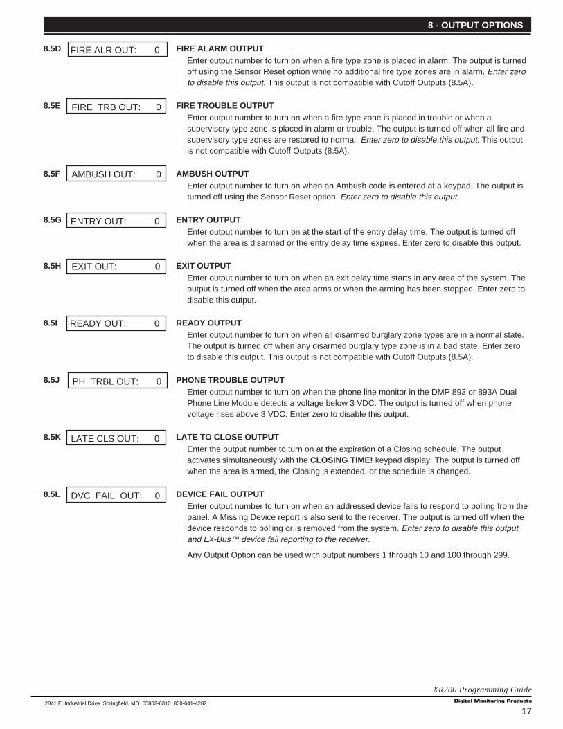
8.5D FIRE ALARM OUTPUTEnter output number to turn on when a fire type zone is placed in alarm. The output is turnedoff using the Sensor Reset option while no additional fire type zones are in alarm. Enter zeroto disable this output. This output is not compatible with Cutoff Outputs (8.5A).
8.5E FIRE TROUBLE OUTPUTEnter output number to turn on when a fire type zone is placed in trouble or when asupervisory type zone is placed in alarm or trouble. The output is turned off when all fire andsupervisory type zones are restored to normal. Enter zero to disable this output. This outputis not compatible with Cutoff Outputs (8.5A).
8.5F AMBUSH OUTPUTEnter output number to turn on when an Ambush code is entered at a keypad. The output isturned off using the Sensor Reset option. Enter zero to disable this output.
8.5G ENTRY OUTPUTEnter output number to turn on at the start of the entry delay time. The output is turned offwhen the area is disarmed or the entry delay time expires. Enter zero to disable this output.
8.5H EXIT OUTPUTEnter output number to turn on when an exit delay time starts in any area of the system. Theoutput is turned off when the area arms or when the arming has been stopped. Enter zero todisable this output.
8.5I READY OUTPUTEnter output number to turn on when all disarmed burglary zone types are in a normal state.The output is turned off when any disarmed burglary type zone is in a bad state. Enter zeroto disable this output. This output is not compatible with Cutoff Outputs (8.5A).
8.5J PHONE TROUBLE OUTPUTEnter output number to turn on when the phone line monitor in the DMP 893 or 893A DualPhone Line Module detects a voltage below 3 VDC. The output is turned off when phonevoltage rises above 3 VDC. Enter zero to disable this output.
8.5K LATE TO CLOSE OUTPUTEnter the output number to turn on at the expiration of a Closing schedule. The outputactivates simultaneously with the CLOSING TIME! keypad display. The output is turned offwhen the area is armed, the Closing is extended, or the schedule is changed.
8.5L DEVICE FAIL OUTPUTEnter output number to turn on when an addressed device fails to respond to polling from thepanel. A Missing Device report is also sent to the receiver. The output is turned off when thedevice responds to polling or is removed from the system. Enter zero to disable this outputand LX-Bus™ device fail reporting to the receiver.
Any Output Option can be used with output numbers 1 through 10 and 100 through 299.
8 - OUTPUT OPTIONS
READY OUT: 0
LATE CLS OUT: 0
PH TRBL OUT: 0
DVC FAIL OUT: 0
ENTRY OUT: 0
EXIT OUT: 0
FIRE ALR OUT: 0
FIRE TRB OUT: 0
AMBUSH OUT: 0

18
XR200 Programming Guide2841 E. Industrial Drive Springfield, MO 65802-6310 800-641-4282
9.1 MENU DISPLAYMenu Display allows you to select at which keypad addresses the user can access thefollowing functions.
A description of each menu option follows:
9.2 ARMED STATUSEnter the keypad addresses that show the armed areas for their partitions. For example: ifaddress 1 is enabled here, it can display the armed areas within its partition. Each armedarea is displayed with its area number. The User Menu Armed Areas function also displaysthe custom area name you enter in the Area Information section of the Programmer.
9.3 TIMEEnter the keypad addresses that can display the time and day of the week.
9.4 ARM/DISARMEnter the keypad addresses from which users can arm and disarm areas in a partition.
10.1 STATUS LISTThis function allows you to select the zone alarms and troubles, and system monitor troublesdisplayed at the keypads. The Status List function operates automatically when the keypad isnot performing any other function.
The keypad stays in the Status List until the user chooses to go to system arming/disarmingor a menu option. Status List alternates with the Armed Status on keypad addresses selectedin section 9.2. You can choose to have System Monitor troubles placed in the list, thedifferent zone types placed in the list, and at which keypad addresses they'll display.
A description of how each is displayed in the Status List follows:
10.2 DISPLAY KEYPADSThis option defines which keypad addresses display the various status information. Anycombination of addresses can be entered to display the status items that follow. If you don'twant a particular status item to display, do not enter any addresses.
10.3 SYSTEM MONITOR TROUBLESSpecifies the addresses where any trouble on a System Monitor is displayed. The SystemMonitors are:
AC Power
Battery Power
Panel Box Tamper
Phone Line 1
Phone Line 2 (requires the 893 or 893A Dual Phone Line Module)
The name of the System Monitor is placed in the Status List and the keypad steady troublebuzzer sounds. The buzzer remains on until any top row SELECT key is pressed on thekeypad. The name remains in the list until the condition is restored.
9 - MENU DISPLAY
10 - STATUS LIST
MENU DISPLAY
STATUS LIST
SYS TRB 12345678
DISPLAY KEYPADS:
ARM STAT 12345678
TIME DSP 12345678
ARM/DIS 12345678

192841 E. Industrial Drive Springfield, MO 65802-6310 800-641-4282
XR200 Programming Guide
10.4 FIRE ZONESSpecifies the addresses where all fire zone alarms and troubles are displayed. The zonename is displayed and, if it's a trouble condition, the keypad steady trouble buzzer sounds.The buzzer remains on until any top row SELECT key is pressed. The name remains in thelist until the user clears it with the Sensor Reset function.
When using the 690, 693, 790, 791, or 793 Security Command LCD Keypads, the XR200provides distinct speaker tones from the keypad for Fire. See below:
Fire On - Fire zone alarm and Bell Output or Fire Bell Output is ON.
Off - Alarm Silence.
10.5 BURGLARY ZONESSpecifies the addresses where all burglary zone alarms and troubles are displayed. Burglaryzones include Night, Day, and Exit type zones. Burglary zone troubles remain in the list untilthe zone restores.
For zone alarms, only the last burglary zone tripped remains in the list. The alarm remains inthe list until another burglary zone goes into alarm, any area of the system is disarmed, or 10minutes elapses without an alarm. This ensures that if a burglary is in progress the last zonetripped remains in the list even if the zone has been restored.
The keypad buzzer sounds for one second on burglary alarms.
When using the 690, 693, 790, 791, or 793 Security Command LCD Keypads, the XR200provides distinct speaker tones from the keypad for Burglary. See below:
Burglary On - Burglary zone alarm and Bell Output or Burglary Bell Output is ON.
Off - Alarm Silence.
10.6 SUPERVISORY ZONESSpecifies the addresses where all supervisory zone alarms and troubles are displayed.Supervisory zones are entered in the status list and sound the keypad buzzer until a validuser code is entered at any keypad address.
10.7 PANIC ZONESSpecifies the addresses where all panic zone alarms and troubles are displayed. The nameof the zone remains in the list until the zone restores. The keypad buzzer does not sound forpanic alarms or troubles.
10.8 EMERGENCY ZONESSpecifies the addresses where all emergency zone alarms and troubles are displayed. Thename of the zone remains in the list until the zone restores. The keypad buzzer does notsound for emergency alarms or troubles.
10.9 AUXILIARY 1 ZONESSpecifies the addresses where all Auxiliary 1 zone alarms and troubles are displayed. Thename of the zone remains in the list until the zone restores. The keypad buzzer does notsound for Auxiliary 1 alarms or troubles.
10.10 AUXILIARY 2 ZONESSpecifies the addresses where all Auxiliary 2 zone alarms and troubles are displayed. Thename of the zone remains in the list until the zone restores. The keypad buzzer does notsound for Auxiliary 2 alarms or troubles.
10 - STATUS LIST
FIRE 12345678
SPRVSRY 12345678
AUX 1 - - - - - - - -
EMERGCY- - - - - - - -
AUX 2 - - - - - - - -
BURGLRY 12345678
PANIC - - - - - - - -

20
XR200 Programming Guide2841 E. Industrial Drive Springfield, MO 65802-6310 800-641-4282
11.1 PRINTER REPORTSThis section allows you to define the operation of a local printer connected to the panelthrough the use of a DMP 462P Printer Interface Card. The 462P allows you to connect theDMP SCS-PTR or other compatible 40 or 80 character serial printer to the XR200 panel.
Printing the panel's event buffer
The Display Events option in the User Menu contains a PRINT command that allows the userto send the contents of the panel's event buffer to a local printer. The PRINT option is visiblewhether or not a 462P Printer Interface Card is attached to the panel.
11.2 ARM AND DISARM REPORTSPrints arming, disarming, and Late to Close reports. Includes the area number, name, andaction (armed, disarmed, or late), the user number, user name, and time and date.
11.3 ZONE REPORTSPrints changes in the status of active zones. Includes the zone number, name, and type aswell as the action (alarm, trouble, bypass, etc.) user number (if applicable) and area name.
11.4 USER COMMAND REPORTSPrints user code changes, outputs turned on or off (if operated by a schedule, SCH is shownin Display Events in place of the user number), schedule changes, and User Menu functions.
11.5 DOOR ACCESS REPORTSPrints door access activity. Includes the door number, user number and name, and the timeand date of the door access.
11.6 SUPERVISORY REPORTSPrints System Monitor Troubles and system events. See section 10.3.
12.1 AREA INFORMATIONAllows you to assign functions to the different areas within a partition. All non-24 hour zonesmust be assigned to an active area. See Zone Information in section 13.1.
You activate an area by assigning it a name. See section 12.13. A name is given to eachactive area in place of a number to assist the user during arming and disarming.
12.2 PARTITION NUMBEREnter the partition number to program. Partition 1 using area arming can have up to eightareas on the XR200 panel. Partitions 2, 3, and 4 using area arming can each have up to fourindependent areas.
This prompt is not displayed if you only entered one partition in Device Setup.
12.3 ARMING MODEThis option allows you to program how the areas in this partition operate. If the Model 485 isused this option does not display and is automatically set to AREA. The options you canchoose are:
AREA ARMING - in which all areas of the partition can be programmed and operatedindependently. Partition 1 provides up to eight areas and partitions 2 to 4 each provide up tofour areas.
ALL/PERIMETER - in which only areas one and two are activated and operate as aperimeter and interior system only.
11 - PRINTER REPORTS
PRINTER REPORTS
ARM/DIS NO
DOOR ACS NO
SUPV MSG NO
ZONE NO
USR CMDS NO
12 - AREA INFORMATION
MODE: AREA SYS
AREA A / P H / A
AREA INFORMATION
PARTITION NO: 1

212841 E. Industrial Drive Springfield, MO 65802-6310 800-641-4282
XR200 Programming Guide
HOME/AWAY - in which three areas can be used: Perimeter, Interior, and Bedrooms. If youassign zones to the Bedrooms area, the keypad display shows HOME SLEEP AWAY whenthe user goes to arm the system. If you do not assign zones to the Bedrooms area, thekeypad only displays HOME AWAY to the end user.
With the HOME SLEEP AWAY option, the user can:
1. Select HOME to arm just the perimeter.
2. Select SLEEP to arm the perimeter and interior (non bedroom areas).
3. Select AWAY to arm all three areas.
12.4 EXIT DELAYEnter the exit delay time for all Exit type zones in this partition. When the exit delay timestarts, all activity on that zone and other non-24 hour zone types in the area are ignored untilthe exit delay expires. This delay countdown is displayed on the keypad.
If an Exit zone is in a bad condition at the end of the exit delay:
• the alarm bell sounds for 15 seconds• an Exit Error report is sent to the central station receiver
• the bad Exit zone is force armed
If any other zone type is placed in a bad condition at the end of the exit delay an alarm isindicated. The exit delay can be from 1 to 250 seconds.
Enter zero to disable the Exit Delay feature.
12.5 BURGLARY BELL OUTPUTEnter the output number (0 to 10, 100 to 299 or D1 to D16 if Model 485 is used) that is turnedon any time a Burglary type zone in this partition is placed in alarm. The output is turned offwhen you disarm the area in which the alarm occurred and no other Burglary type zones arein alarm. The output can also be turned off using the Alarm Silence option in the User Menuor by entering a user code with the authority to silence alarms. The duration of this bell outputfollows the time entered in the System Options/Bell Cutoff Time prompt. See section 8.2. IfBell Test is YES (see section 8.3), the Burglary Bell Output entered here is turned on for twoseconds each time the system is armed.
12.6 OPENING/CLOSING REPORTSThis option allows an Opening report to be sent to the receiver whenever an area within thispartition is disarmed. A Closing report is also sent to the receiver when any area within thispartition is armed.
12.7 CLOSING CHECKSelect YES to enable the panel to verify that all areas in this partition have been armed aftertemporary or permanent schedules have expired. If the Closing Check finds any areasdisarmed past the scheduled time, the keypad selected to display System Trouble Statusemits a steady beep and displays CLOSING TIME! .
If you select Area Schedules in section 12.10, the appropriate area name is displayedfollowed by - LATE . The keypad's steady beep is silenced by pressing any top row SELECTkey. If the system is not armed or a temporary schedule not entered to extend the closingwithin ten minutes, a no closing report is sent to the SCS-1 Receiver if AUTO ARM is NO.See section 12.15. If the area has been disarmed outside of any permanent or temporaryschedule, the closing check sequence occurs one hour after the area is disarmed andcontinues each hour until the area is armed or the schedule is extended.
12.8 CLOSING CODEWhen YES is selected, a code number is required for system arming. If NO is selected, acode number is not required for system arming.
12 - AREA INFORMATION
OPN/CLOS YES
CLS CHK NO
CLS CODE NO
EXIT DELAY: 45
BURG BEL OUT: 0

22
XR200 Programming Guide2841 E. Industrial Drive Springfield, MO 65802-6310 800-641-4282
12.9 ANY BYPASSWhen YES is selected, zones can be bypassed without a code number during the armingsequence. A code number is always required to use the Bypass Zones option from the menu.
12.10 AREA SCHEDULESSelect YES to allow each area in this partition to set its own permanent and temporary, orprimary and secondary user disarming schedules. Enter NO to provide one set of userdisarming schedules for each partition.
12.11 PRIMARY/SECONDARY SCHEDULESSelect YES to provide primary and secondary schedules for this partition or each area withinthis partition depending on the Area Schedules option selected in section 12.10. Enter NO touse permanent and temporary schedules.
Choosing Schedules
Primary and Secondary schedules are ideal for auto arming and disarming of individual areasand for creating Opening/Closing windows during which users with a level 1 or 2 authoritycan disarm the system. Having two separate schedules allows you to create two Opening/Closing windows for each day. One could be for normal business activity and the other couldbe for cleaning crews or a second shift. Once programmed, these schedules operatecontinually until changed.
Permanent schedules are identical to Primary and Secondary schedules and can be used forthe same purposes. Temporary schedules however, once programmed, expire at the end oftheir closing time and must be programmed again. This feature allows you to create atemporary schedule that lets a delivery or repairman disarm and occupy an area for aspecified time without the schedule occurring again.
12.12 AREA NUMBEREnter the number of the area in this partition you are programming. In an area system,partition 1 can have up to 8 areas. Partitions 2 to 4 can each have up to 4 areas. Afterentering the area number, press COMMAND to enter the area name.
12.13 AREA NAMEThe area name can be up to 16 alphanumeric characters. All others are marked unused. Forinstructions on entering alphanumeric characters, refer to section 1.7. To add an area nameto the system, press any SELECT key and then enter up to 16 characters for the new areaname. Press COMMAND to continue.
To mark an active area unused, delete the old name by pressing a top row SELECT key,then press the COMMAND key. The programmer automatically programs the name as*UNUSED*. If you have already cleared Area Information during Initialization, all areas will bemarked * UNUSED *. See section 2.6.
12.14 ACCOUNT NUMBEREnter the account number to be sent to the receiver for this area. Choose an account numbercompatible with the Communication Type selected in section 3.2. The default accountnumber is the one previously entered in section 3.4. If the Communication Type selected insection 3.2 is multiplex, you must choose an account number between 128 and 999.
Below illustrates proper assignment of multiplex account numbers to DMP SCS-1 Receivers:
Receiver Line Main Account # Area Account #1 10000 to 10127 10128 to 109992 20000 to 20127 20128 to 209993 30000 to 30127 30128 to 309994 40000 to 40127 40128 to 409995 50000 to 50127 50128 to 50999
12 - AREA INFORMATION
* UNUSED *
ANY BYPS NO
AREA SCH NO
PRI/SEC NO
AREA NO: –
ACCOUNT NO: 12345
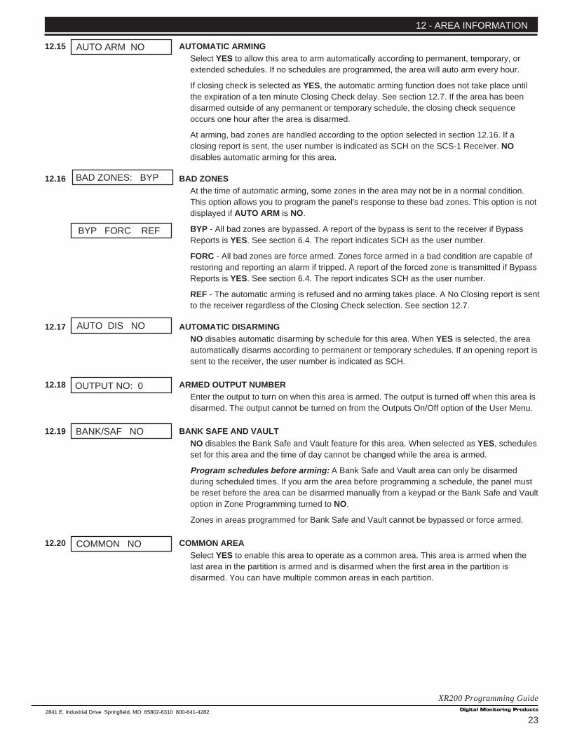
232841 E. Industrial Drive Springfield, MO 65802-6310 800-641-4282
XR200 Programming Guide
12.15 AUTOMATIC ARMINGSelect YES to allow this area to arm automatically according to permanent, temporary, orextended schedules. If no schedules are programmed, the area will auto arm every hour.
If closing check is selected as YES, the automatic arming function does not take place untilthe expiration of a ten minute Closing Check delay. See section 12.7. If the area has beendisarmed outside of any permanent or temporary schedule, the closing check sequenceoccurs one hour after the area is disarmed.
At arming, bad zones are handled according to the option selected in section 12.16. If aclosing report is sent, the user number is indicated as SCH on the SCS-1 Receiver. NOdisables automatic arming for this area.
12.16 BAD ZONESAt the time of automatic arming, some zones in the area may not be in a normal condition.This option allows you to program the panel's response to these bad zones. This option is notdisplayed if AUTO ARM is NO.
BYP - All bad zones are bypassed. A report of the bypass is sent to the receiver if BypassReports is YES. See section 6.4. The report indicates SCH as the user number.
FORC - All bad zones are force armed. Zones force armed in a bad condition are capable ofrestoring and reporting an alarm if tripped. A report of the forced zone is transmitted if BypassReports is YES. See section 6.4. The report indicates SCH as the user number.
REF - The automatic arming is refused and no arming takes place. A No Closing report is sentto the receiver regardless of the Closing Check selection. See section 12.7.
12.17 AUTOMATIC DISARMINGNO disables automatic disarming by schedule for this area. When YES is selected, the areaautomatically disarms according to permanent or temporary schedules. If an opening report issent to the receiver, the user number is indicated as SCH.
12.18 ARMED OUTPUT NUMBEREnter the output to turn on when this area is armed. The output is turned off when this area isdisarmed. The output cannot be turned on from the Outputs On/Off option of the User Menu.
12.19 BANK SAFE AND VAULTNO disables the Bank Safe and Vault feature for this area. When selected as YES, schedulesset for this area and the time of day cannot be changed while the area is armed.
Program schedules before arming: A Bank Safe and Vault area can only be disarmedduring scheduled times. If you arm the area before programming a schedule, the panel mustbe reset before the area can be disarmed manually from a keypad or the Bank Safe and Vaultoption in Zone Programming turned to NO.
Zones in areas programmed for Bank Safe and Vault cannot be bypassed or force armed.
12.20 COMMON AREASelect YES to enable this area to operate as a common area. This area is armed when thelast area in the partition is armed and is disarmed when the first area in the partition isdisarmed. You can have multiple common areas in each partition.
12 - AREA INFORMATION
BANK/SAF NO
BYP FORC REF
BAD ZONES: BYP
AUTO ARM NO
AUTO DIS NO
COMMON NO
OUTPUT NO: 0

24
XR200 Programming Guide2841 E. Industrial Drive Springfield, MO 65802-6310 800-641-4282
13.1 ZONE INFORMATIONZone Information allows you to define the operation of each protection zone used in thesystem. All protection zones, whether located on a command processor panel, SecurityCommand keypad, or zone expander are programmed the same way.
A description of each specification follows:
13.2 ZONE NUMBEREnter the number of the zone you intend to program. Press COMMAND to enter a zonename. For instructions on entering alphanumeric characters, see section 1.7.
13.3 ZONE NAMEZone names can have up to 16 alphanumeric characters. A name must be given to eachzone in the system. The name can display at the keypads during arming and disarming sothe user does not have to memorize zone numbers. Users can associate a zone name with aparticular protection point. A zone that is not part of the system must be marked unused.
To add a zone name to the system, press any SELECT key and then enter up to 16characters for the new zone name. Press COMMAND to continue.
To mark a zone unused, delete the old name by pressing a top row SELECT key, then pressthe COMMAND key. The programmer automatically programs the name as * UNUSED *. Ifyou have already cleared Zone Information during Initialization, the zones will be marked *UNUSED *. See section 2.5.
13.4 ZONE TYPEThe Zone Type defines the panel's response to the zone being opened or shorted. This iscalled the Alarm Action. There are up to 13 possible alarm action responses depending onthe zone type and any restrictions it may have. See the chart in section 13.6.
When you assign a Zone Type to a zone, responses are made automatically for the zone.There are 12 Zone Types to choose from. Application descriptions for each zone type can befound in the Appendix section of this manual.
To enter a new Zone Type, press any SELECT key. The display lists all of the availableZone Types four at a time.
Blank, Night, Day, or Exit. Press COMMAND for additional zone types.
Fire, Panic, Emergency, or Supervisory. Press COMMAND for additional zone types.
Auxiliary 1, Auxiliary 2, Fire Verify, or Arming (keyswitch). Press the ARROW key to displaythe previous zone types. When the Zone Type you want is displayed, press the SELECT keybeneath it.
If you select Blank, Night, Day, Exit, Auxiliary 1, Auxiliary 2, or Arming as the Zone Type, thezone must be assigned to an active area. If you select Fire, Fire Verify, Panic, Emergency, orSupervisory as the Zone Type, it's a 24 hour zone that is always armed and no areaassignment is needed.
Zone Type Specifications
The XR200 contains 12 default zone types for use in configuring the system. These zonetypes provide the most commonly selected functions for their applications. All zone typesexcept the Arming zone type can be customized by changing the options listed below.
Refer to section 16.6 in the Appendix for complete zone type descriptions.
13 - ZONE INFORMATION
ZONE NO: -
ZONE INFORMATION
ZONE TYPE: BLANK
* UNUSED *
– – NT DY EX
A1 A2 FV AR
F I PN EM SV

252841 E. Industrial Drive Springfield, MO 65802-6310 800-641-4282
XR200 Programming Guide
13.5 FIRE BELL OUTPUTThis output (1 to 10, 100 to 299 or D1 to D16 if the Model 485 is used) is turned on any timea Fire, Fire Verify, or Supervisory zone is placed in alarm. The output is turned off by any thefollowing actions:
• When the User Menu Alarm Silence function is performed.
• When a valid user code is entered to silence the bell.
• Using the Outputs On/Off function in the User Menu.
• The expiration of the Bell Cutoff time. See section 8.2.
13.6 PARTITION NUMBEREnter the partition number where this zone is being assigned.
13.6A AREA NUMBERFor an Area system, enter the area number where this zone is being assigned.
13.6B AREA ASSIGNMENTFor an All/Perimeter system, choose INT. (interior) or PERIM (perimeter). For a Home/Awaysystem, choose INT (interior), BDRM (bedroom), or PERIM (perimeter). Press the SELECTkey under your selection.
13.6C ARMING ZONE AREA ASSIGNMENTIf the zone has been programmed as an Arming Type (AR), the only information to enter isthe areas the zone controls. If the Arming zone is in a partition programmed as an Areasystem, enter the area numbers to be armed and disarmed.
If the partition is in an All/Perimeter system, select either PERIM (perimeter) or ALL .
If the partition is in a Home/Away system, select HOME (for the perimeter area), SLEEP (forperimeter and interior areas), or AWAY (for perimeter, interior, and bedrooms areas).
How the Arming zone works (momentary keyswitches)
When the Arming zone is shorted from a normal condition, arming and disarming is done ona toggle basis. If any or all areas are armed, they'll be disarmed. If all areas are disarmed,they'll be armed. If the Arming zone is opened while any areas it controls are armed, aburglary alarm occurs. If the zone is restored to normal, the areas cannot be disarmed usingthe Arming zone until at least one other area within the same partition is disarmed remotely,from a keypad, or from another Arming zone.
If the Arming zone is opened while all areas assigned to it are disarmed, a burglary troubleoccurs. If the zone restores to normal, a burglary restoral occurs.
To visually indicate the armed state of the area(s), you can assign an Armed Output toindividual areas and use remote LEDs at the keyswitch. The LED turns on or off to indicate tothe user the armed state of the area(s).
If any bad zones are present when the Arming zone is shorted, the LED delays lighting forfive seconds. If during the five second delay the Arming zone is shorted again, no armingtakes place. To force arm bad zones, the Any Bypass option must be set to YES. See section12.9. A priority zone cannot be force armed.
13.7 NEXT ZONEWhen YES is selected, the programming for the zone terminates and the display returns tosection 13.2 allowing you to enter a new zone number. To make any alterations to the AlarmAction for a zone, answer the Next Zone prompt with NO. The Alarm Action is then defined insections 13.9 through 13.17.
Zones 100 through 299 have wireless capability: If you are programming zones 100 to 299, selecting NO to NEXTZONE - NO YES displays the prompt WIRELESS NO. This display is not visible unless you are programming zonesin this range. If the zone you are programming is intended for wireless devices, select YES and refer to theprogramming instructions below. Select NO to continue programming non-wireless zones in the 100 to 299 range.
13-ZONE INFORMATION
AREA NO: -
FIRE BEL OUT: 0
AREAS : 1 2 3 4
AREA : PERIMETER
PARTITION NO: 1
PER IM ALL
HOME SLEEP AWAY
NEXT ZN? NO YES

26
XR200 Programming Guide2841 E. Industrial Drive Springfield, MO 65802-6310 800-641-4282
13.7A WIRELESSSelect YES if you are programming a wireless zone. Press the COMMAND key to continuewith wireless programming.
13.7B CHECK IN TIMEYou can set transmitters to check in automatically every 10, 30, or 60 seconds or not at all.To change the default of 60 seconds, press any SELECT key to display the default display ofNONE 10 30 60. Press the SELECT key under the check in time you want for this zone.
13.7C INTERNAL CONTACTSelect YES to use an internal contact on the wireless transmitter. Select NO to use anexternal contact. When NO, the following two prompts are displayed.
13.7D END OF LINESelect YES to supervise an external contact connected to the transmitter. At the contact,install a 2.2k Ω End Of Line resistor in parallel for Normally Open contacts and in series forNormally Closed contacts.
13.7E NORMALLY OPENSelect NO if the contact connected to the transmitter is a Normally Closed type.
13.8 ALARM ACTIONThis option allows you to change the standard definitions of any Zone Type. The AlarmAction for a zone is stored in memory when the Zone Type is specified in section 13.4.
If the Zone Type is Blank, Night, Day, Exit, Auxiliary 1, or Auxiliary 2 it's a non-24 hour zoneand the Alarm Action programing begins with Disarmed Open.
If the Zone Type is Fire, Panic, Emergency, or Supervisory it's a 24 hour zone that is alwaysarmed and the Alarm Action programming begins with Armed Open.
The Fire Verify Zone Type functions the same as Fire Type, with the following exceptions:When a Fire Verify zone initiates an alarm, the panel performs a Sensor Reset. If any FireVerify zone initiates an alarm within 120 seconds after the reset, an alarm is indicated. If analarm is initiated after 120 seconds, the cycle is repeated and a zone fault report is sent tothe receiver.
Do NOT program Fire Verify Zone Types for Zone Retard. See section 13.16.
13.9 DISARMED OPENDefines the action taken by the panel when the zone is opened while the area is disarmed.There are three actions to define:
Report to transmit Relay Output to activate Relay Output action
You must also make these selections for the Disarmed Short, Armed Open, and Armed Shortzone conditions. Press COMMAND to continue. A description of each selection follows:
13.9A REPORT TO TRANSMITYou can send two report types to the SCS-1 Receiver: Alarm and Trouble. These areprogrammed by the characters A and T. Press any top row SELECT key to display thefollowing report options.
ALARM - Selecting A, allows an alarm report to be sent to the receiver and the bell output toactivate according to zone type. See section 8.4, Bell Action. The zone name appears in thepanel's alarmed zones and status lists.
TROUBLE - Selecting T allows a trouble report to be sent to the receiver and the zone nameto appear in the panel's alarmed zones and status lists.
13 - ZONE INFORMATION
WIRELESS NO
CHECK IN TM: 60
INT CONT NO
E O L NO
NRM OPEN YES
DISARMED OPEN
ALARM ACTION . . . .
MSG: TROUBLE
A T L
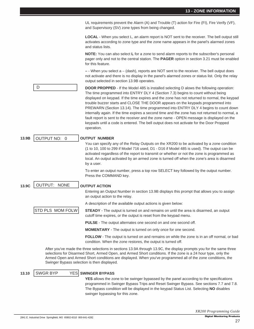
272841 E. Industrial Drive Springfield, MO 65802-6310 800-641-4282
XR200 Programming Guide
UL requirements prevent the Alarm (A) and Trouble (T) action for Fire (FI), Fire Verify (VF),and Supervisory (SV) zone types from being changed.
LOCAL - When you select L, an alarm report is NOT sent to the receiver. The bell output stillactivates according to zone type and the zone name appears in the panel's alarmed zonesand status lists.
NOTE: You can also select L for a zone to send alarm reports to the subscriber's personalpager only and not to the central station. The PAGER option in section 3.21 must be enabledfor this feature.
– - When you select a – (dash), reports are NOT sent to the receiver. The bell output doesnot activate and there is no display in the panel's alarmed zones or status list. Only the relayoutput selected in section 13.9B operates.
DOOR PROPPED - If the Model 485 is installed selecting D alows the following operation:The time programmed into ENTRY DLY 4 (Section 7.3) begins to count without beingdisplayed on keypad. If the time expires and the zone has not returned to normal, the keypadtrouble buzzer starts and CLOSE THE DOOR appears on the keypads programmed intoPREWARN (Section 13.14). The time programmed into ENTRY DLY 4 begins to count downinternally again. If the time expires a second time and the zone has not returned to normal, afault report is sent to the receiver and the zone name - OPEN message is displayed on thekeypads until a code is entered. The bell output does not activate for the Door Proppedoperation.
13.9B OUTPUT NUMBERYou can specify any of the Relay Outputs on the XR200 to be activated by a zone condition(1 to 10, 100 to 299 if Model 716 used, D1 - D16 if Model 485 is used). The output can beactivated regardless of the report to transmit or whether or not the zone is programmed aslocal. An output activated by an armed zone is turned off when the zone's area is disarmedby a user.
To enter an output number, press a top row SELECT key followed by the output number.Press the COMMAND key.
13.9C OUTPUT ACTIONEntering an Output Number in section 13.9B displays this prompt that allows you to assignan output action to the relay.
A description of the available output actions is given below:
STEADY - The output is turned on and remains on until the area is disarmed, an outputcutoff time expires, or the output is reset from the keypad menu.
PULSE - The output alternates one second on and one second off.
MOMENTARY - The output is turned on only once for one second.
FOLLOW - The output is turned on and remains on while the zone is in an off normal, or badcondition. When the zone restores, the output is turned off.
After you've made the three selections in sections 13.9A through 13.9C, the display prompts you for the same threeselections for Disarmed Short, Armed Open, and Armed Short conditions. If the zone is a 24 hour type, only theArmed Open and Armed Short conditions are displayed. When you've programmed all of the zone conditions, theSwinger Bypass selection is then displayed.
13.10 SWINGER BYPASSYES allows the zone to be swinger bypassed by the panel according to the specificationsprogrammed in Swinger Bypass Trips and Reset Swinger Bypass. See sections 7.7 and 7.8.The Bypass condition will be displayed in the keypad Status List. Selecting NO disablesswinger bypassing for this zone.
13 - ZONE INFORMATION
SWGR BYP YES
OUTPUT: NONE
STD PLS MOM FOLW
OUTPUT NO: 0
D

28
XR200 Programming Guide2841 E. Industrial Drive Springfield, MO 65802-6310 800-641-4282
How it worksIf a zone trips the total number of times specified in section 7.7 within one hour, the panelbypasses it until either the area in which the zone is assigned is disarmed, the zone ismanually reset through the Bypass Zones? keypad User Menu function, or the zone remainsnormal for one hour and the Reset Swinger Bypass is YES. See section 7.8.
If the zone trips fewer than the specified times within one hour, the bypass trip counterreturns to zero and the process must be repeated.
A report of the swinger bypass is sent to the receiver if Bypass Reports is YES. See section6.4.
13.11 FAST RESPONSESelect YES to provide a zone response time of 167ms. Select NO to provide a normal zoneresponse time of 500ms. Zones 100 to 299 have a fixed response time of 200ms and do notdisplay this prompt.
13.12 CROSS ZONESelect YES to enable cross zoning for this zone. Cross zoning requires one or more armedzones to fault within a programmed time before an alarm report is sent to the receiver.
When a cross zoned zone trips, the bell action assigned to the zone activates. The crosszone time specified in section 7.4, System Options, begins to count down. If another crosszoned zone in the same area faults, or if the first zone restores and faults again before aSensor Reset is done , the panel sends an alarm report.
If no other cross zoned zone in the same area trips before the cross zone time expires, thepanel sends only a zone fault report to the receiver.
Cross zoning is not compatible with all zone types: You cannot enable cross zoning for Fire verify zones or forany Fire zone type that has Retard Delay set to YES.
13.13 PRIORITYSelect YES to provide additional protection for the premises by requiring this zone to be in anormal condition before its assigned area can be armed.
ZONE NUMBER - Enter the zone number to program next. Return to section 13.2 and followthe descriptions of each programming prompt. If all zones are programmed, press theARROW key at the ZONE NO: – display to continue.
Note: If you programmed any wireless zones, press the ARROW key for the following wireless programming.
13.13A PROGRAM TRANSMITTERSelect YES to program wireless transmitters. Select NO to return to ZONE INFORMATION.
13.13B CONNECT TRANSMITTERConnect the transmitter, whose zone number is displayed, to the Programming Connector on
the 472 HARD-WIRE-LESS Card using the 620 Programming Cable. RESET THETRANSMITTER. The keypad display prompts you for transmitters starting from the lowestzone number to the highest.
At the CONNECT XMTR: prompt, you can also press a SELECT key and enter in anywireless zone number (100 to 299 or 000 for the C100 and FA100 transmitters). Afterprogramming all transmitters, press the COMMAND key.
13.13C CONNECT COMMAND TRANSMITTERConnect the C100 or FA100 you want assigned to the partition shown (P1 = Partition 1) tothe 472 Card. Press the Alert button on the transmitter to initiate programming. Repeat theprogramming for each partition. To use the Alert button on the transmitter as a panic,program AMBUSH as YES in System Reports.
13 - ZONE INFORMATION
FAST RSP NO
CRS ZONE NO
PRIORITY NO
ZONE NO: –
CONNECT C100 P 1
PRG XMTR? NO YES
CONNECT XMTR: ***

292841 E. Industrial Drive Springfield, MO 65802-6310 800-641-4282
XR200 Programming Guide
Additional Zone ProgrammingThe remaining Zone Information you need to specify varies with the different Zone Types.Below is a list of the remaining information needed and the section numbers:
If Zone Type Remaining Information Section Numbers
Exit Prewarn addresses/Entry Delay Sections 13.15 to 13.16
Fire, Supervisory, Retard and Presignal addresses Sections 13.17 to 13.18
Auxiliary 1 and 2
13.14 PREWARN ADDRESSESAt the start of the entry delay, all keypad addresses selected here display ENTER CODE:-. Ifyou want the prewarn to sound at all eight addresses, leave the default as shown.
To delete an address, press the matching number on the keypad. To disable prewarning atall keypads, press a top row key to clear the addresses shown. Press the COMMAND keywhen the address selection is complete.
13.15 ENTRY DELAYSelect the entry timer for this zone. Entry timers 1 to 4 are programmed in section 7.3.
13.16 ZONE RETARDWhen you select YES, the zone operates with the retard delay specified in section 7.5. Theretard functions only in zone short conditions.
The zone must remain shorted for the full length of the retard delay before the panelrecognizes its condition. If you select NO, the zone operates without a retard delay.
13.17 PRESIGNAL ADDRESSESYou can enable any combination of keypad addresses to sound a presignal tone during thetime a zone is in retard delay. The presignal tone silences when the zone restores or theretard delay expires.
To enable a presignal address, press any top row SELECT key followed by the number of thekeypad address. You can enable the presignal for all eight keypad addresses. To disable apresignal address press the matching number digit again. Press the COMMAND key whenthe address selection is complete. The Presignal prompt is only displayed when Retard isselected as YES.
PREWARN: 12345678
RETARD NO
ENTRY DELAY: 1
PRESGNL: NONE
13 - ZONE INFORMATION

30
XR200 Programming Guide2841 E. Industrial Drive Springfield, MO 65802-6310 800-641-4282
14.1 STOPAt the STOP prompt, pressing any SELECT key allows you to exit the Programmer functionof the XR200 panel. When selected, the panel performs an internal reset and exits theprogrammer.
The STOP routine causes the following conditions to occur:
• All areas in all partitions are DISARMED
• All zones in all partitions are DISARMED
• The panel's Status List is CLEARED
During the reset, all keypad displays are momentarily blank for two seconds. After the reset,the programming function is terminated and the keypads return to the status list display.
Missing LX-Bus™ Modules Displayed
The XR200 Programmer includes a feature following the STOP routine that displays the name of any programmedLX-Bus module not currently connected to the panel. For example, if you had enabled any of the wireless options andnot yet installed a 472 HARD-WIRE-LESS Card, after the STOP routine the panel would display NO WIRELESS CARD .This is a helpful reminder to install the card. This feature can also be a troubleshooting tool that could indicate aproblem if you had installed the card and still saw this message displayed. The following list shows the differentmessages and their associated LX-Bus cards.
Keypad Display Missing Card
NO LXBUS CARD 481 LX-Bus™ Expansion Card
NO WIRELESS CARD 472 HARD-WIRE-LESS™ Card
NO PRINTER CARD 462P Printer Interface Card
NO DNET CARD 462N Network Interface Card
NO HOST CARD 462N Network Interface Card (with HOST communication selected)
The above messages clear automatically from the keypad after a few moments.
15.1 SET LOCKOUT CODEPressing COMMAND at the STOP prompt displays SET LOCKOUT CODE. This allows youto program a code that will then be required to gain access to the panel's internalProgrammer through the keypad. You can change this code at any time to any combinationof numbers from 3 to 5 digits long.
Once you have changed the code, it is important to write it down somewhere and store it in asafe place. Lost Lockout Codes require the panel to be sent back to DMP for repair.
Lockout Code restriction
Do not set a Lockout Code higher than 65535.
SET LOCKOUT CODE
STOP
14 - STOP
15 - SET LOCKOUT CODE

312841 E. Industrial Drive Springfield, MO 65802-6310 800-641-4282
XR200 Programming Guide
16.1 Events ManagerThe XR200 Events Manager function allows you to delay sending certain reports to the central station receiver.Reports can be kept in the panel's memory until overwritten by new activity or held until the memory buffer reaches133 events, 665 door access granted events if the Model 485 Access Control Expansion card is used. When thebuffer is filled, the panel automatically sends the stored reports to the central station receiver. Below is a list of XR200reports that can be delayed using the Events Manager option:
16.2 Zone type descriptionsThis section describes applications for the default zone types in Zone Information programming.
NT (Night Zone) - Controlled instant zone used for perimeter doors and windows and interior devices such as PIRsand Glassbreak detectors.
DY (Day zone) - Used for emergency doors or fire doors to sound the keypad buzzer and display the zone namewhen the zone is faulted. Day zones also will send alarm reports to the receiver during the system's armed periods.
EX (Exit zone) - Initiates the entry delay timer when its assigned area is fully armed. Also, can initiate an exit delaytimer to allow a user to exit an area after the arming process has started.
PN (Panic zone) - Used for connecting to mechanical devices that allow a user to signal an emergency alarm. Paniczones can provide either a silent or audible alarm with or without reporting to a central station receiver.
EM (Emergency zone) - These are used for reporting medical or other non-panic emergencies to the central stationreceiver.
SV (Supervisory zone) - Used to provide 24-hour zone supervision to devices associated with fire systems. Typicalapplications are tamper switches on Post Indicator Valves (PIVs), gate valves, and low and high temperature gauges.
FI (Fire zone) - Used for any type of powered or mechanical fire detection device. Typical applications are for smokedetectors, sprinkler flowswitches, manual pull stations, and beam detectors. Retard, cross zoning, and pre-signaloptions are available for the Fire zone type.
FV (Fire Verify zone) - Used primarily for smoke detector circuits to verify the existence of an actual fire condition.When a Fire Verify zone initiates an alarm, the panel performs a Fire Reset. If any Fire Verify zone initiates an alarmwithin 120 seconds after the reset, an alarm is indicated. If an alarm is initiated after 120 seconds, the cycle isrepeated.
A1 and A2 (Auxiliary 1 and Auxiliary 2) - These zones are similar to a Night zone and are typically used to protectrestricted areas within a protected premises.
AR (Arming zone) - This zone allows you to connect a keyswitch on a zone and use it to arm and disarm one or moreareas within a partition.
16 - APPENDIX
Immediately Delayed Report TypeY AlarmY TroubleY Restore
Y OpeningY Closing
Y BypassY ResetY Supervisory
Y Add CodesY Delete CodesY Change CodesY Permanent Schedule ChangeY Temporary Schedule ChangeY Door Access
Y Door Access DeniedY Late To CloseY Force Armed Loop

32
XR200 Programming Guide2841 E. Industrial Drive Springfield, MO 65802-6310 800-641-4282
16.3 Diagnostics functionThe XR200 panel contains a Diagnostics function that allows test the communication integrity of the LX-Bus™,identify individual zones, and also display the present electrical state of any zone. To use Diagnostics, reset thepanel, enter the Diagnostics code 2313 (DIAG), and press COMMAND.
TEST LX-BUSThe first Diagnostic function you'll see displayed is: TEST LX-BUS . This function allows you to test the ability of the462N, 462P, 472, and 481 Interface Cards to communicate with zone and output expander modules connected totheir LX-Bus™ circuits.
To continue, press any top row SELECT key. The keypad displays LX-BUS 1 2 . Press the SELECT key under 1 totest LX-Bus circuit number 1. Press the SELECT key under 2 to test LX-Bus circuit number 2. The keypad nowdisplays ADDRESS: - . Enter a 2-digit LX-Bus address to which you have assigned a device and press COMMAND.
Important Note: A device address is not the same as a zone number. If you are testing 714 or 715 Zone ExpanderModules, which each contain four zones, the device address is the first zone number. When the panel polls a 714 or715 on the LX-Bus, it recognizes them as four zone devices and skips polling the remaining three zones (these arepolled internally by the module, which then transmits any status changes to the panel). This polling of addressesgreatly reduces the amount of time it takes the panel to poll all devices on the LX-Bus.
When testing LX-Bus devices, enter only the addresses to which the modules have been set.
The keypad next displays TESTING . . . STOP during the testing of the device. At any time, you can press theSELECT key under STOP to end the polling. The panel now records the number of no responses from the device. Ifall polls are received back by the panel correctly, the keypad displays 00000/65535 FAIL. The 0 (zero) represents thenumber of failed polling responses.
If one or more polling attempts fail, the keypad displays * * * * */65535 FAIL . (The * * * * * represents the number ofpolling attempts that failed.) A display of 65535/65535 FAIL indicates a problem with the interface card or its LX-Buswiring such as a bad or broken wire, harness not properly connected, or excessive noise or distance. It can alsomean that a zone number was entered that did not match a device address. Press the ARROW key to enter a newdevice address or press COMMAND to exit the TEST LX-BUS option.
ZONE FINDERThe second Diagnostic function is the Zone Finder. Press the COMMAND to display ZONE FINDER. This functionallows you to identify individual zones on devices connected to the LX-Bus of an interface card, the panel, or anyzones on the keypad data bus. To use ZONE FINDER, press any top row SELECT key. The display changes toFAULT ZONE . The next zone on the system that changes from a normal to an open or shorted state is displayed asZONE NO: * * *. To continue, press the ARROW key.
ZONE STATEPress the COMMAND to display the third Diagnostic function: ZONE STATE. This function allows you to enter anyzone number and check its current electrical state (Normal, Open, or Shorted). Press any SELECT key. The displaychanges to ZONE NUMBER: _ . Enter in the number of the zone you want to check and press COMMAND. Thepanel then displays the current state of the zone as either NRML (normal), OPEN, or SHORT.
LX-BUS STATUSThe fourth Diagnostic function is the LX-BUS STATUS . This function allows the panel to poll all devices connected tothe LX-Bus of an interface card and check for any Overlapped, Missing, or Extra addresses. Below is a description ofeach status item:
Overlap - An overlap occurs when two or more devices are set to the same address.
Missing - A missing occurs when a zone between 100 and 299 has been programmed in ZONE INFORMATION andno device with that zone's address has been installed on the LX-Bus. For example, if zone 110 has beenprogrammed but the device has not been installed or has been set to another address, the zone cannot be found bythe panel and a MISSING is displayed here in LX-BUS STATUS . To correct the problem, check your zoneprogramming and addressing of zone expansion modules.
Extra - A device is installed on the LX-Bus but none of its zones are programmed into the system.
Exiting the Diagnostics programTo exit the Diagnostics function, press the ARROW key until you see the display STOP then press any top rowSELECT key. The keypad returns to the Status List display.
16 - APPENDIX
332841 E. Industrial Drive Springfield, MO 65802-6310 800-641-4282
XR200 Programming Guide
16.4 Using the 984 Command FunctionThe 984 Command function allows you to connect the panel with a service receiver at a remote location for thepurpose of remote programming, retrieving the Event Buffer, or checking one or more elements of the currentprogram. To use the function, enter the numbers 9, 8, and 4 (984) and press COMMAND. The keypad displaychanges to NBR RMT PICKUP .
NBR (number) - Select NBR if you want to enter a number for the panel to dial to reach the service receiver. Phonenumbers can be up to 15 characters in length. You can program a three second pause in the dialing sequence byinserting the letter P before the number. You can program a dial tone detect by inserting the letter D. Thesecharacters are counted as part of the allowable 15 characters.
RMT (remote phone number) - Select RMT if you want the panel to immediately seize the phone line and dial thephone number programmed into the Remote Options section of the program. See section 5.8. The Remote Optionsphone number is to the modem being used by the DMP Remote Access™ software program.
PICKUP - Select this option if the person attempting the remote programming is currently ringing the phone line ontowhich the panel is connected. Once the panel picks up the line, a verification process occurs and, if successful, thepanel grants remote access to its programming and Event Buffer.
Keypad Displays
When either the RMT or PICKUP options are used, the keypad displays LINE SEIZED. This indicates that the panelhas seized the line and is executing its program. If the line cannot be accessed, or if the RMT or PICKUP options areused before all connects attempts are made, the keypad displays SYSTEM BUSY.
16.5 690 Series Keypads Speaker OperationWhen using the 690, 693, 790, 791, or 793 Security Command LCD Keypads, the XR200 provides distinct speakertones from the keypad for Fire, Burglary, Zone Monitor, and Prewarn events. The list below details the conditionsunder which the speaker is turned on and off for each event.
Fire On - Fire zone alarm and Bell Output or Fire Bell Output is ON.Off - Alarm Silence.
Burglary On - Burglary zone alarm and Bell Output or Burglary Bell Output is ON.Off - Alarm Silence.
Zone Monitor On - One time only when a monitored zone is tripped.Off - After one tone.
Prewarn On - During Entry Delay.Off - When Entry Delay expires.
16.6 Cross ZoningCaution must be taken when cross zoning devices to ensure that the Cross Zone Time (section 7.4) is long enough toallow an intruder to trip both devices before it expires. A Cross Zone Time that is too short may allow an intruder totrip the devices and have just a zone fault report sent to the central station.
16 - APPENDIX

34
XR200 Programming Guide2841 E. Industrial Drive Springfield, MO 65802-6310 800-641-4282
– = This function is not enabled for this zone type.
+ = Retard must be YES before Presignal can be selected.
= These zone functions are not available for this zone type.
Description of the programmable zone optionsBelow is a description of the various zone options shown on the table above. For additional information, read throughthe Zone Information section of this manual.
Zone Type Defaults - These are complete spellings of the abbreviations used for the zone types.
Type - These are the abbreviations used for the zone types.
RF - This zone is connected to a wireless transmitter.
Message - A = alarm report, T = trouble report, L = local with no report, - (dash) = no report.
Output - These are the ten on-board and 200 off-board relay outputs.
Action - This selects the action of the output: S = steady, P = pulse, M = momentary, and F = follow
Swinger - The zone can be automatically shunted after a programmed number of trips.
Prewarn - This selects the keypad address that sounds the entry prewarn for this zone.
Entry Delay - This is the entry delay timer selected as the default for this zone.
Retard Delay - Provides a programmed retard time before an alarm is initiated from a shorted zone.
Presignal - Provides a keypad tone for zones in retard delay.
Fast Response - Provides a 167ms zone response instead of the normal 500ms response.
Cross Zone - Provides cross zoning with any of the 242 available zones.
Priority - Requires this zone to be in a normal condition before the area can be armed.
Digital Monitoring Products2841 E. Industrial Drive Springfield, MO 65802-6310 800-641-4282
16 - APPENDIX
16.7 Zone Type Specifications
ZONE INFORMATION Type Area Fire RF Disarmed Disarmed Armed Armed– – NT Open Short Open Short
Assign area and disarm condition Bellfor NT, DY, EX, A1, A2, and ARonly
DY EX
OtputAssign Prewarn and Entry Delay FI PNfor EX only
EM SV 1 Y A 1 S A 1 S A 1 S A 1 S N 1 1 N 1 N N NAssign Retard and Pesignal for FI, SV, A1, A2, and FV only A1 A2
1to or T to P T to P T to P T to P or to to or to or or or
FV AR to 1 - 8 10 N L 10 M L 10 M L 10 M L 10 M Y 8 4 Y 8 Y Y Y
Zone type defaults Abbr.
4 100 to
299D1to
D16
–D
100 to
299D1to
D16
F–D
100 to
299D1to
D16
F–D
100 to
299D1to
D16
F–D
100 to
299D1to
D16
F
NIGHT NT – 0 – – 0 – A 0 – A 0 – Y N N NDAY DY T 0 – T 0 – A 0 – A 0 – Y N N NEXIT EX – 0 – – 0 – A 0 – A 0 – Y 1-8 1 N N NFIRE FI T 0 – A 0 – N N + N N NPANIC PN T 0 – A 0 – N N N NEMERGENCY EM T 0 – A 0 – N N N NSUPERVISORY SV T 0 – A 0 – N N + N N NAUXILIARY 1 A1 T 0 – A 0 – T 0 – A 0 – N N + N N NAUXILIARY 2 A2 T 0 – A 0 – T 0 – A 0 – N N + N N NFIRE VERIFY FV T 0 – A 0 – N N NARMING AR
Mes
sage
Out
put
Act
ion
Mes
sage
Out
put
Act
ion
Mes
sage
Out
put
Act
ion
Mes
sage
Out
put
Act
ion
Sw
inge
r
Pre
war
n
Ent
ry D
elay
Ret
ard
Del
ay
Pre
sign
al
Fas
t Res
pons
e
Cro
ss Z
one
Prio
rity
Par
titio
n N
umbe
r