y · interpretation of results ... reactor coolant system depressurization ... management guides...
TRANSCRIPT

IAEA-TECDOC-1002
Use of PSA Level 2 analysisfor improving
containment performanceReport of a Technical Committee meeting
held in Vienna, 9-13 December 1996
INTERNATIONAL ATOMIC ENERGY AGENCY puu—\
March 1998

The IAEA does not normally maintain stocks of reports in this series.However, microfiche copies of these reports can be obtained from
IN IS ClearinghouseInternational Atomic Energy AgencyWagramerstrasse 5P.O. Box 100A-1400 Vienna, Austria
Orders should be accompanied by prepayment of Austrian Schillings 100,-in the form of a cheque or in the form of IAEA microfiche service couponswhich may be ordered separately from the INIS Clearinghouse.

The originating Section of this publication in the IAEA was:Safety Assessment Section
International Atomic Energy AgencyWagramerstrasse 5
P.O. Box 100A-1400 Vienna, Austria
USE OF PSA LEVEL 2 ANALYSIS FORIMPROVING CONTAINMENT PERFORMANCE
IAEA, VIENNA, 1998IAEA-TECDOC-1002
ISSN 1011-4289
©IAEA, 1998
Printed by the IAEA in AustriaMarch 1998

FOREWORD
Containment performance could have an important role in determining the consequencesof severe accidents in nuclear facilities and so containment capabilities are increasingly beinganalysed in probabilistic safety assessments (PSAs). These studies provide a basis for studyingthe effects of upgrading measures or of additional, new equipment intended to improvecontainment response and to reduce accident consequences. They are also used to investigatesevere accident management.
In 1992 a Safety Series report on Probabilistic Safety Assessment was produced by theInternational Nuclear Safety Advisory Group (INSAG) as 75-INSAG-6. This report states thatthe methods and tools available to analyse containment response to severe accidents still containsignificant uncertainties which make application of such studies difficult.
In order to discuss and exchange experience on different aspects of methods associated withLevel 2 PSA and its applications for improving containment performance, the IAEA held aTechnical Committee meeting in Vienna in December 1996. The meeting, which was attendedby 26 participants from 20 Member States, provided a broad forum for discussion. The meetingaddressed the issues related to the actual performance of Level 2 PSA studies as well as theinsights gained from applications to improve containment performance. Particular attention wasgiven to studies and applications for WWER type reactors, for which Level 2 work is still in itsearly stages, and for channel type reactors where modelling of accident progression is complexand significantly different from vessel type light water reactors.
This TECDOC contains the papers presented at the meeting and the results of extensivediscussions which were held in specific working groups.

EDITORIAL NOTE
In preparing this publication for press, staff of the IAEA have made up the pages from theoriginal manuscripts as submitted by the authors. The views expressed do not necessarily reflectthose of the IAEA, the governments of the nominating Member States or the nominatingorganizations.
Throughout the text names of Member States are retained as they were when the text wascompiled.
The use of particular designations of countries or territories does not imply any judgement bythe publisher, the IAEA, as to the legal status of such countries or territories, of their authoritiesand institutions or of the delimitation of their boundaries.
The mention of names of specific companies or products (whether or not indicated asregistered) does not imply any intention to infringe proprietary rights, nor should it be construedas an endorsement or recommendation on the part of the IAEA.
The authors are responsible for having obtained the necessary permission for the IAEA toreproduce, translate or use material from sources already protected by copyrights.

CONTENTS
1. INTRODUCTION . . . . . . . . . . . . . . . . . . . . . . . . . . . . . . . . . . . . . . . . . . . . . . . . . . . . . . . . . . . 1
2. OBJECTIVES OF THE MEETING . . . . . . . . . . . . . . . . . . . . . . . . . . . . . . . . . . . . . . . . . . . . . 1
3. REVIEW OF EXPERIENCE . . . . . . . . . . . . . . . . . . . . . . . . . . . . . . . . . . . . . . . . . . . . . . . . . . 2
3.1. Session 1, vessel type LWRs (except WWERs) . . . . . . . . . . . . . . . . . . . . . . . . . . . . . . . . 23.2. Session 2, WWER type reactors . . . . . . . . . . . . . . . . . . . . . . . . . . . . . . . . . . . . . . . . . . . . 53.3. Session 3, channel type reactors . . . . . . . . . . . . . . . . . . . . . . . . . . . . . . . . . . . . . . . . . . . . 7
4. USE OF PSA LEVEL 2 ANALYSIS FOR IMPROVINGCONTAINMENT PERFORMANCE . . . . . . . . . . . . . . . . . . . . . . . . . . . . . . . . . . . . . . . . . . . . 8
4.1. Accident management measures for LWRs . . . . . . . . . . . . . . . . . . . . . . . . . . . . . . . . . . 104.2. Use of Level 2 PSA analysis for improving containment performance -
specific aspects of WWER type reactors . . . . . . . . . . . . . . . . . . . . . . . . . . . . . . . . . . . . 11
5. IMPORTANT ISSUES . . . . . . . . . . . . . . . . . . . . . . . . . . . . . . . . . . . . . . . . . . . . . . . . . . . . . . 14
5.1. General issues . . . . . . . . . . . . . . . . . . . . . . . . . . . . . . . . . . . . . . . . . . . . . . . . . . . . . . . . . 145.1.1. Scope and objectives of a Level 2 PSA . . . . . . . . . . . . . . . . . . . . . . . . . . . . . . . 145.1.2. Organization and project management . . . . . . . . . . . . . . . . . . . . . . . . . . . . . . . 145.1.3. Quality of the Level 2 PSA . . . . . . . . . . . . . . . . . . . . . . . . . . . . . . . . . . . . . . . . 145.1.4. Compilation of plant features, familiarization with the plant . . . . . . . . . . . . . . 155.1.5. Analysis of containment performance . . . . . . . . . . . . . . . . . . . . . . . . . . . . . . . . 155.1.6. Accident progression analysis . . . . . . . . . . . . . . . . . . . . . . . . . . . . . . . . . . . . . . 165.1.7. Development and quantification of the Level 2 PSA model . . . . . . . . . . . . . . . 165.1.8. Uncertainty and sensitivity analysis . . . . . . . . . . . . . . . . . . . . . . . . . . . . . . . . . 175.1.9. Interpretation of results . . . . . . . . . . . . . . . . . . . . . . . . . . . . . . . . . . . . . . . . . . . . 175.1.10. Issues related to the application of information and results . . . . . . . . . . . . . . . . 17
5.2. WWER specific issues . . . . . . . . . . . . . . . . . . . . . . . . . . . . . . . . . . . . . . . . . . . . . . . . . . . 175.2.1. WWER-1000 . . . . . . . . . . . . . . . . . . . . . . . . . . . . . . . . . . . . . . . . . . . . . . . . . . . 175.2.2. WWER-440 (both versions, 230 and 213) . . . . . . . . . . . . . . . . . . . . . . . . . . . . . 19
5.3. Specific issues for channel type reactors . . . . . . . . . . . . . . . . . . . . . . . . . . . . . . . . . . . . 19
6. FINAL REMARKS . . . . . . . . . . . . . . . . . . . . . . . . . . . . . . . . . . . . . . . . . . . . . . . . . . . . . . . . . 20
LIST OF ABBREVIATIONS . . . . . . . . . . . . . . . . . . . . . . . . . . . . . . . . . . . . . . . . . . . . . . . . . . . . . . 22
ANNEX: PAPERS PRESENTED AT THE TECHNICAL COMMITTEE MEETING
A proposal for accident management optimization based on thestudy of accident sequence analysis for a BWR . . . . . . . . . . . . . . . . . . . . . . . . . . . . . . . . . . . 27M. Sobajima
Parametric model to estimate containment loads following ex-vessel steam spike . . . . . . . . . . . . . 37R. Lopez, J. Hernandez, A. Huerta
State of Level 2 analyses and severe accident management in Spanishnuclear power plants . . . . . . . . . . . . . . . . . . . . . . . . . . . . . . . . . . . . . . . . . . . . . . . . . . . . . . . . 45R. Otero
Analysis of feedwater accidents with the MELCOR code for the WWER-440/213 NPP . . . . . . . . 53G.L. Horvath

Overview and current state of the Level 2 PSA for the Balakovo WWER-1000:Analysis of containment performance . . . . . . . . . . . . . . . . . . . . . . . . . . . . . . . . . . . . . . . . . 61/ Kalinkin
Strategies for operation of containment related ESFs in managing activity release to theenvironment during accident conditions ... . . . . . . . . . . . . . . . . . . . . . . . . . . . . . . 69RN Bhawal,S.S Bajaj
Analytical studies related to Indian PHWR containment system performance . . . . . . . . . . . . . . . 81S.K Haware, S.G. Markandeya, A.K. Ghosh, H.S. Kushwaha, V. VenkatRaj
Approach to development and use of PSA Level 2 analysis for theCemavoda nuclear power plant . . . . . . . . . . . . . . . . . . . . . . . . . . . . . . . . . . . . . . . . . . . . . . . 97I Turcu, R Deaconu, G. Radu
PSA Level 2 activities for RBMK reactors . . . . . . . . . . . . . . . . . . . . . . . . . . . . . . . . . . . . . . . . . . . 107R Gubler
LIST OF PARTICIPANTS . . . . . . . . . . . . . . . . . . . . . . . . . . . . . . . . . . . . . . . . . . . . . . . . . . . . . . .119
1. INTRODUCTION
Level 1 probabilistic safety assessments (PS As) have been or are currently being performedfor most nuclear power plants (NPPs) worldwide. Level 1 PSA determines whether accidentsequences may result in fuel or core damage. In Level 2 PSA the course of core damagesequences is further considered in terms of accident progression, physical phenomena within thecontainment, containment response and releases, as well as transport of radioactive materialswithin the containment and to the environment. The main task of the Level 2 PSA is to assesscontainment failure modes and source terms of radioactive materials to the environment of theplant. Source terms are given by the amount of different types of radioactive materials releasedand the characteristics of the release, e.g. release height, energy and timing. Based on the sourceterms, off-site consequences are then estimated in the Level 3 PSA.
In addition to the Level 1 PSAs Level 2 analyses have been already carried out, are inprocess or planned for all major reactor types. The information and results of these studies areused to identify weak points or vulnerabilities of the containment and containment systems undersevere accident conditions. Level 2 PSA is used to study the effects of upgrading measures or ofadditional, new equipment intended to improve containment and containment systems responseand to reduce accident consequences. It is also used to investigate severe accident management.Severe accident management tries to limit or mitigate severe accidents and their consequencesby refining emergency operation procedures using either existing, newly added, or improvisedequipment and systems.
The investigation and implementation of upgrading measures intended to improvecontainment and containment systems behaviour under severe accident conditions and to reducethe consequences of severe accidents cannot be done based on Level 2 PSA alone due to thelimited level of detail and the uncertainties in methods, models and data. Dedicated detailedanalyses of specific phenomena with specialized computer codes, engineering type studies andsometimes even experiments are necessary for this purpose. However, PSA provides thenecessary overall framework to consider, for example, negative and positive impacts of plannedupgrading measures and also allows to carry out cost-benefit analyses.
2. OBJECTIVES OF THE MEETING
The purpose of the Technical Committee Meeting was to bring about a broad exchange ofinformation in the area of using Level 2 PSA for improving containment performance.Furthermore, it provided the opportunity to identify present capabilities and limitations of Level2 methodology, in particular regarding the different types of NPPs and the correspondingconfinements or containments. The specific objectives of the meeting were to review the currentapproaches, experiences and practices in Member States in the use of Level 2 PSA for improvingcontainment performance, to discuss pertinent issues and to make recommendations on areas andaspects which need further development.
To achieve the above objectives, the Technical Committee meeting consisted ofpresentations and discussions. Special attention was given to aspects of Level 2 analyses forWWER and channel type reactors. Participants from 13 Member States took the floor on nineoccasions and presented an additional nine papers. The papers are reproduced in an annex to thisreport.

3. REVIEW OF EXPERIENCE
This section contains summaries of individual presentations. Table I lists the PSArequirements in the Member States represented at the meeting. The presentations were organizedin three sessions according to the types of reactors considered:
(1) Vessel type LWRs (with the exception of WWERs which were considered in Session 2,see below);
(2) WWER type reactors;(3) Channel type reactors.
3.1. SESSION 1, VESSEL TYPE LWRs (EXCEPT WWERs)
In the first presentation, A. D'Eer, Belgium, described recent Level 2 PSA work for NPPsin Belgium. The plants considered were Tihange Unit 1, a 3-loop PWR, and Doel Units 1 and 2which are 2-loop PWRs. The following specific accident management features and measures wereconsidered for the Doel 1 and 2 units:
hydrogen catalytic recombinersreactor coolant system depressurizationreactor cavity flooding
- external vessel coolingindependent containment heat removal.
It is planned to carry out detailed modelling and evaluation of plant specific severe accidentmanagement guides which are currently being drawn up. The performance of source termcalculations, to be used as a basis for planning emergency exercises, is also contemplated.
The presentation of M. Kajimoto, Japan, summarized Level 2 studies performed forreference BWR and PWR NPPs. The calculated results show low containment failure frequenciesand illustrate the high safety level which has been achieved for both reactor types. Accidentmanagement is addressed in terms of the concept of defence in depth. For early containmentfailure, the dominant accident sequences are anticipated transients without scram (ATWS) for thereference BWR, and steam generator tube rupture (SGTR) for the reference PWR. Thephenomena of steam explosion, pressure spike at reactor vessel failure and direct containmentheating (DCH) are not contributing significantly regarding dominant sequences that lead tocontainment failure. This includes consideration of uncertainty bands. Late containment failureswith loss of heat removal are dominant accident sequences which have a relatively high frequencyand source terms.
The paper of M. Sobajima, Japan, describes a proposal for accident managementoptimization based on the study of accident sequence and source term analyses for a BWR.Specific aspects of the presentation were the following:
Accident management measures are to be implemented in all LWRs by 2000 in accordancewith the regulator's recommendation and the utility's PSA Level 1.5;
- Source terms were evaluated by JAERI in all BWR sequences with the THALES code inwhich loss of decay heat removal resulted in the largest release;

TABLE I. REQUIREMENTS FOR PSA IN MEMBER STATES
NPP CountryType
LWRs Belgium
Brazil
Germany
India
Islamic Republicof Iran
Japan
Republic of Korea
Mexico
Netherlands
Pakistan
Spain
UK
WWERs Czech Republic
Hungary
Russian Federation
Slovakia
PHWRs Canada
India
Pakistan
Romania
Republic of Korea
RBMKs Russian Federation
PSA Level 1
Required"
Required
Required
Suggested1
Required
Strongly suggested
Required
Required
Required
Suggested
Required
Required
Voluntary
Required
Required
Required
Suggested
Suggested
Voluntary
Required
Required
Required
" 'Required': Officially required in the regulations.' Suggested' : Not officially required in the regulations,
PSA Level 2
Partly required b
Voluntary
Studies ongoing_ c
Required
Strongly suggested
Suggested
Required
Required
Voluntary
Required
Required
Voluntary
planned
Desirable
Voluntary
Voluntary
Voluntary
Voluntary
Required
Suggested
Desirable
PSA Level 3
_ c
_ c
_ c
_ c
_ c
_ c
_ c
Desirable
Required
Voluntary_ c
Required
Voluntary_ c
_ c
_ c
Voluntary
Voluntary
Voluntary
Required_ c
_ c
but the regulatory organization may verylikely request the licensee to perform a PSA
b Limited to containment performance analysis.c No requirement or no information available.
Identification of the priority and importance of accident management measures was madefor the sequences with larger risk contributions;
Consideration for optimizing emergency operation guides is essential for risk reduction.

The contribution of See Darl Kim, Republic of Korea, described a systematic sensitivitystudy performed to assess the effects of advanced safety features of the Korean standard NPP.The specific advanced safety features considered designed to mitigate severe accidents were thereactor cavity flooding system, hydrogen igniters, and the containment filtered venting system.It was shown that the reactor cavity flooding system and the igniters do not enhance containmentperformance in a significant way. In contrast, the containment filtered venting system appearedto be effective. This result is thought to be a consequence of the specific containment design, inparticular because of the relatively high failure pressure.
The paper of/?. Lopez Morones, Mexico, considers the use of a relatively simple parametricmodel to estimate containment loads following an ex-vessel steam spike. Specific aspects of hispresentation were the following:
- The study was initiated because several PSAs identified containment loads accompanyingreactor vessel failure as a major contributor to early containment failure.
The description of the simple but physically sound parametric model which was adoptedto estimate containment loads following a steam spike into the reactor cavity.
The contribution ofP.J.T. Bakker, Netherlands, described the PSA work carried out for theBorssele and Dodewaard NPPs. A full scope PSA Level 3 analysis for all NPPs was required inthe Netherlands. Both NPPs fulfilled this requirement for their 'as-built' status. The methodsapplied were based on NUREG-1150 and used the MELCOR, MAAP, WAVCO, EVNTRE andNUCAP+ codes. Modifications to the containment will be made based in part on the Level 2 PSAresults. The most important modifications concern filtered vent systems, dry well bottomprotection and hydrogen recombination systems. The update of the PSA to the new layout showsa clear improvement of the containment performance. The Borssele PSA is also used to study AM(accident management) measures. The detailed study showed that the important core damagefrequencies out of the Level 1 PSA are not the most significant in terms of the environmentalimpact according to the Level 3 PSA. The containment bypass sequences, with a low frequencybut high consequence, can be reduced with appropriate AM measures. These AM measures basedon the PSA lead to a further improvement of the 'containment' performance.
The paper ofR. Otero, Spain, presents the increasing scope of PSATPE (individual plantexamination) analyses required to the Spanish NPP by the Spanish Regulatory Commission(CSN), and the state of Level 2 analyses in each plant. The strategy envisaged for theimplementation of severe accident management hi Spanish LWRs was also shown in hispresentation. The main phenomena and key equipment for containment performance wereidentified for two specific Spanish plants, a PWR and a BWR, whose Level 2 studies are eitherunder preparation or development.
The presentation ofC.H. Shepherd, United Kingdom, considered the full scope Level 3 PSAcarried out for the Sizewell B PWR. This included a level 2 PSA to determine the effectivenessof the containment in preventing an uncontrolled release of radioactivity to the environmentfollowing core melt. The small containment event tree approach with 20 nodes in 4 time frameswas used to model the phenomena which could challenge the integrity of the containment. Thephenomena addressed included fuel coolant interaction, hydrogen bum, detonation, high pressuremelt ejection, direct containment heating, etc. The phenomena were modelled using MAAPsupported by other codes and taking account of recent research on these topics. The failure of thecontainment due to overpressure was modelled using a finite element analysis. This predicted that

gross failure would occur at 2.6 times the design pressure due to failure of the cylindrical wallsand that enhanced leakage would occur at 2.4 times the design pressure due to the liner tearingat the equipment hatch and personnel airlock. This was confirmed by a tenth scale model test. Theanalyses addressed a number of accident management measures and concluded that there was asignificant benefit from recovery of the emergency core cooling system (ECCS) and the reactorbuilding spray system and the use of the reactor building spray system to put water into thecontainment. However, the analyses determined that there would be no significant benefit fromthe incorporation of a filtered containment venting system.
3.2. SESSION 2, WWER TYPE REACTORS
The presentation of L. Kucera, Czech Republic, examined the results and experiences madein the Level 2 PSA for the Temelin NPP. The Temelin NPP is still under construction, thereforethe PSA study has been based on a number of conservative assumptions. For this reason, the PSALevel 1 and Level 2 gave somewhat pessimistic results, such as large early releases due to a highcontribution of containment bypass and early containment failure sequences. When realistic dataon the plant is available (such as detailed design data, success criteria based on deterministiccalculations, emergency operating procedures (EOP), etc.) and consequently the Level 2 PSAgives more realistic results, it is expected that these results will be widely used in the preparationof severe accident management guidance as well as in the discussion on measures to improveplant and containment performance.
Recently a project was started during which a database of the most probable and/or severeaccidents was created based on results of the Level 2 PSA. In the event of an accident, thisdatabase should assist the technical support centre in understanding the progress of the accidentand determining the measures to be taken.
The presentation of B. Kujal, Czech Republic, analysed the work related to WWER-1000containment behaviour and loads during severe accidents. The systematic examination of thephenomena and mechanisms which can result in the loss of containment function in the courseof severe accidents was performed in the Nuclear Research Institute Pic. Rez (Czech Republic).
The following phenomena were identified to be the most relevant:
- long term overpressurization- hydrogen bums- steam explosions
direct containment heatingcorium penetration through the hermetic boundary.
The MELCOR, CONTAIN and WECHSL codes were used for analyses. Input model andinput data files were prepared under quality assurance. Extensive analysis (including sensitivitystudies) of all the phenomena mentioned above resulted in the following conclusions:
Direct containment heating and steam explosions do not seem to be a real danger for theWWER-1000 containment.
Long term overpressurization, hydrogen detonations and in particular corium penetrationthrough the bottom floor plate of the containment are the real threats for the containmentfunction.

The results of the analysis were used for severe accident management proposals and willbe utilized in the revised version of the Level 2 PS A study for the Temelin NPP.
Level 2 PSA related studies in Hungary are described in the paper of G.L. Horvath,Hungary. A Level 1 PSA has been performed for the PAKS Unit 3 in the framework of theAGNES project, which is an overall safety reassessment project for this plant. The current PSAtopics being considered are shutdown PSA and human reliability. Limited Level 2 PSA studieswere also performed for the AGNES project. The analytical tools available for the Level 2 workare STCP, CONTAIN, MELCOR, RELAP-SCDAP, and MAAP. Most of these codes are runningat VEIKI. Good experience is available for STCP, CONTAIN and MELCOR, and experience isbeing gained using MAAP and RELAP-SCDAP. Still more experience with all the codes isneeded.
The applicability of available analytical tools for containment ultimate failure pressureanalysis for the WWER-440/213 containment is limited. Current active analytical issues are:accident management, quick accident prediction tools (SESAME), hydrogen control and bubblercondenser (large scale) qualification. Level 2 PSA may be initiated in a few years. Theimportance of Level 2 PSA is seen for accident management and in the fact that Level 2 PSA mayresult in dominant sequences different from those of Level 1. Level 2 PSA may be most importantfor authorities and the plant to emphasize also the last barriers. Once most of the Level 1 PSAissues are implemented, Level 2 PSA may be started.
The paper of/. Kalinkin, Russian Federation, describes severe accident related work forthe Balakovo Unit 4. The Level 1 PSA for the Balakovo WWER-1000 Unit 4 has been carriedout and the Level 1-Level 2 PSA interface is developed and represented by a set of interfacingevent trees (using the Risk Spectrum PSA code). The resulting plant damage state (PDS)frequencies were used as input to the containment event tree (GET) developed within the Level2 PSA. Consequences of the GET are grouped into radiological release categories (RCs).Allocation of RCs in the GET is based on the similarity of the sequence characteristics. Each RCmay be quantified in terms of the potential fractions of core inventory that may be released to theenvironment and also by the characteristic of releases such as time to release, release duration andavailability of warning time. Containment capability analysis (with the ABAQUS code) wascarried out and shows a high level of containment ultimate pressure. The containment fragilitycurve was developed taking into account major randomness and uncertainties sources incontainment characteristics. Analysis of containment leakage and of the performance ofpenetrations was also performed. As a result, the containment failure mode under internalpressure rise was defined as a global failure of the containment in the membrane area of thecylinder. As the data on severe accident analysis was only available for a large loss of coolantaccident (LOGA), the quantification of containment event tree (GET) sequences was limited toone sequence. The nodal probabilities were introduced based on data from the analysis of thelarge LOCA, containment fragility curve and expert judgement. The most probable sequence isassociated with low pressure failure of the reactor pressure vessel (RPV) and basematmeltthrough through instrumentation channels with further melting of the foundation slab andrelease to the environment (probability <10~7).
The presentation of E. Shubeiko, Russian Federation, addressed accident progressionanalyses for the NovoVoronezh NPP Units 3 and 4. These units are of the WWER-440, V-179type. The code used for these calculations was MELCOR. The confinement of this plant has alimited capacity and is equipped with pressure relief flaps to limit the pressure rise duringaccidents. Pressure reduction capability in the confinement is provided by means of a

confinement spray with heat exchangers to remove heat. Therefore, it appears that ECCSfunctions and confinement performance are closely connected. In order to account for thisdependency, the integral accident progression code MELCOR was already used in the Level 1accident sequence analysis. The code allows to model confinement performance, confinementsystems, the behaviour of the reactor and reactor coolant system (RCS) in an integral way. Twospecific LOCA sequences were discussed, with leak sizes of 32 mm and 60 mm. It was pointedout that further analyses with a thermohydraulic code like RELAP are needed to determine, forexample, the safety system requirements more precisely.
3.3. SESSION 3, CHANNEL TYPE REACTORS
The paper ofR.N. Bhawal, India, deals with the use of containment safety features to reducesource terms for an Indian PHWR. Level 2 PSA analysis is used for evaluating source terms tothe atmosphere by judging and analysing containment performance. By improving thecontainment safety features, the release can be reduced, resulting in risk minimization. Indianpressurized heavy water reactors (IPHWRs) adopt double containment philosophy extended toall penetrations and other openings such as airlocks. In addition to the special engineered safetyfeatures (ESFs), such as reactor building emergency coolers, a secondary containmentrecirculation and purge system (SCRP), a primary containment filtration and pump back system(PCFPB) and a primary containment controlled discharge system (PCCD) have been incorporatedto enhance the containment performance. In this paper the effectiveness of these different systemsand their interactions in improving containment function have been analysed and discussed. It isseen that the double containment and the SCRP system alone can drastically reduce the releaseof radioactivity. It is also seen that some of the ESFs are effective when operating automatically,while others can be operated manually for better containment performance, depending on theaccident situation. The operator can effectively use PCFPB and PCCD in conjunction with otherinputs like status of other equipment, activity level in the reactor building atmosphere, weathercondition etc. Operators can be provided with appropriate software (plant specific) for on-lineestimation of containment status (Level 2 analysis tool) and take appropriate managementstrategies for effective risk reduction/emergency preparedness.
The analytical tools developed and adapted for PSA Level 2 studies on containment systemperformance for the Indian pressurized heavy water reactor are reviewed in the paper of S.K.Haware, India. Pressure buildup in a multicompartment containment after a postulated accident,the growth, transportation and removal of aerosols in the containment and issues related to thehydrogen behaviour in containment are complex processes of vital importance in deciding thesource term. The necessity of well tested analytical tools to enable proper estimation of the sourceterm and assessment of containment system performance is pointed out.
While the CONTRAN code for containment system thermal hydraulic transient analysishas extensively been validated and NAUA MODS, which performs aerosol behaviour analysis,has been adapted, the HYRECAT code for analysis of hydrogen behaviour and the SPARC codefor suppression pool aerosol scrubbing have undergone a limited degree of validation. With theuse of data from in-house planned tests and other tests, further validation of these codes is athand. Development of an integrated code for containment system performance analysis is inprogress.
D. Serbanescu, Romania, focused in his contribution on the role of PSA in the Romanianregulatory framework. Deterministic and probabilistic approaches are both used for theCemavoda NPP, which is of the CANDU 6 type. Historically, the probabilistic part consisted of

reliability analyses and SDMs (Safety Design Matrices). Furthermore, PS A has been requestedfor this plant, which was restricted to Level 1 for Unit 1, but was extended to Levels 2 and 3 forUnit 2. Accident management measures and features have to be considered as well. Theassessment of containment performance needs to include seismic capacities due to the relativelyhigh seismic hazard at the site. The importance of containment tests and inspections to ascertaincontainment status throughout the operational life was pointed out, as well as careful evaluationof related events at the plant.
The paper of /. Turcu, Romania, first summarizes the status of PSA activities for theCemavoda NPP. The extension of the PSA work to include Level 2 PSA is mentioned. Importantcharacteristics of this reactor type for Level 2 PSA were outlined. Due to the specific layout ofthe CANDU reactor, the evolution of severe accidents is considerably different from vessel typeLWRs. Accidents can be roughly categorized into three categories, 'severe accidents' which leadto the loss of core structural integrity, delayed loss of core structural integrity as a consequenceof the loss of heat sinks, and fuel channel failures. This paper describes the current work formodelling accident progression in the core region and outlines the elements for the Level 2 PSAincluding definition of PDSs, probabilistic containment logic and source term calculation. It ispointed out that uncertainties have to be considered which are contained in the models to bridgeknowledge gaps. For this purpose, sensitivity studies will be carried out for key modellingassumptions.
The paper of R. Gubler, IAEA, describes Level 2 activities for RBMK type reactors.Probabilistic safety analyses (PSAs) of the boiling water graphite moderated pressure tubereactors (RBMKs) have been developed only recently and are limited to Level 1. Activities at theIAEA were first motivated because of the difficulties to characterize core damage for RBMKreactors. Core damage probability is used in documents of the IAEA as a convenient singlevalued measure, for example for probabilistic safety criteria. The limited number of PSAscompleted for the RBMK reactors have shown that several special features of these channel typereactors call for a reexamination of the characterization of core damage for these reactors.Furthermore, it has become increasingly evident that detailed deterministic analysis of designbasis accidents (DBAs) and beyond design basis accidents reveal considerable insights intoRBMK response to various accident conditions. These analyses can also help in bettercharacterizing the outstanding phenomenological uncertainties, improved EOPs and AMstrategies, including potential risk-beneficial accident mitigative backfits. The deterministicefforts should first be directed towards elucidating accident progression processes andphenomena, and second towards finding, qualifying and implementing procedures to minimizethe risk of severe accident states. The IAEA PSA procedures were mainly developed bearing inmind vessel type LWRs, and would therefore require extensions to make them directly applicableto channel type reactors.
4. USE OF PSA LEVEL 2 ANALYSIS FOR IMPROVINGCONTAINMENT PERFORMANCE
The following particular specific uses were identified in the meeting regarding Level 2analysis and containment performance assessment:
Plant, operator environment
- Identification of major containment failure modes and corresponding releases ofradioactivity;

- Identification of human actions important for safety, related to Level 2 PS A;
- Identification of particular important phenomena and processes;
- Identification of specific features, systems, components and equipment of the containmentimportant for safety;
- To gain insights into the progression of severe accidents;
Identification of most effective areas for improvement;
- Investigation of qualification, capacity, operability, and accessibility of containment relatedequipment and structures;
- Basis for upgrading or backfitting of I&C for diagnosis of accident conditions;
- Assessment and planning the use of existing or improvised systems, investigation ofbenefits of existing or new equipment (including 'hardening' or upgrading of existingequipment and systems);
- Identification of operator actions to use existing containment related engineered safetyfeatures in an efficient way;
- Development of severe accident management features, systems and procedures;
- Development of emergency operating procedures;
- Evaluation of technical specifications regarding features important in the Level 2 PS A;
- Prioritization of inspection, testing, surveillance and maintenance related to Level 2 PS A;
- Support for decision making for design modifications, upgrades and backfitting, includingcost-benefit considerations;
- Operator training;
- Planning of emergency exercises;
- Communication means between utility and regulator.
In general, Level 2 information and results are used as a complement for deterministicanalysis and design base considerations.
Regulatory environment
- Evaluation of licensing practices;
- Use of Level 2 PSA in the licensing framework ('risk informed' regulatory policy);
- Support for regulatory decision making (e.g. comparison with probabilistic safety criteria);
9

- Development of severe accident policies;
Regulatory inspection prioritization;
Development of regulatory requirements regarding Level 2 PS A and applications.
Level 2 PSA research and methodology
Basis for prioritization of research activities;
- Gaining insights on particular phenomena and processes which are important forcontainment and containment performance;
- Identification of limitations and uncertainties in current PSA Level 2 methods, knowledgebase and models.
Level 2 PSA also provides the necessary information in terms of releases of radioactivematerial to assess off-site consequences in the Level 3 PSA.
4.1. ACCIDENT MANAGEMENT MEASURES FOR LWRs
A list of current accident management features and measures was compiled by the meetingparticipants. The list below gives an overview of the measures which are under study or areapplied to LWRs for improving containment performance and to reduce source terms. Themeasures are partly based on practical applications in Level 2 studies. The list is restricted to theinformation obtained from the participating countries and does not pretend to be complete.
Cooling of a partly failed core
Use of alternative water sources- Use of alternative power sources
RCS depressurizationWater injection into steam generators
Prevention of induced SGTR
- RCS depressurization- Injection into steam generators- Isolation of the failed steam generator
Prevention of vessel failure
Reactor cavity flooding- RCS depressurization
Control of hydrogen
- Hydrogen recombination- Hydrogen igniters- Post-accident inciting
10
Containment overpressure prevention
- Alternative containment heat removalFiltered venting system
- Natural circulation cooling with air conditioner system- Manually activated spray- Hardened vent from the suppression pool
Basemat meltthrough
- Cavity/pedestal flooding (before and after vessel failure)- Core catchers (advanced LWRs)
Plugging vertical channels which penetrate the reactor cavity floor (WWER-1000)- Provide a pathway for the molten material to flow out of the reactor cavity (WWER-1000)
Source term reduction
- Filtered venting system- Water coverage of the leak in the failed steam generator
4.2. USE OF LEVEL 2 PSA ANALYSIS FOR IMPROVING CONTAINMENTPERFORMANCE — SPECIFIC ASPECTS OF WWER TYPE REACTORS
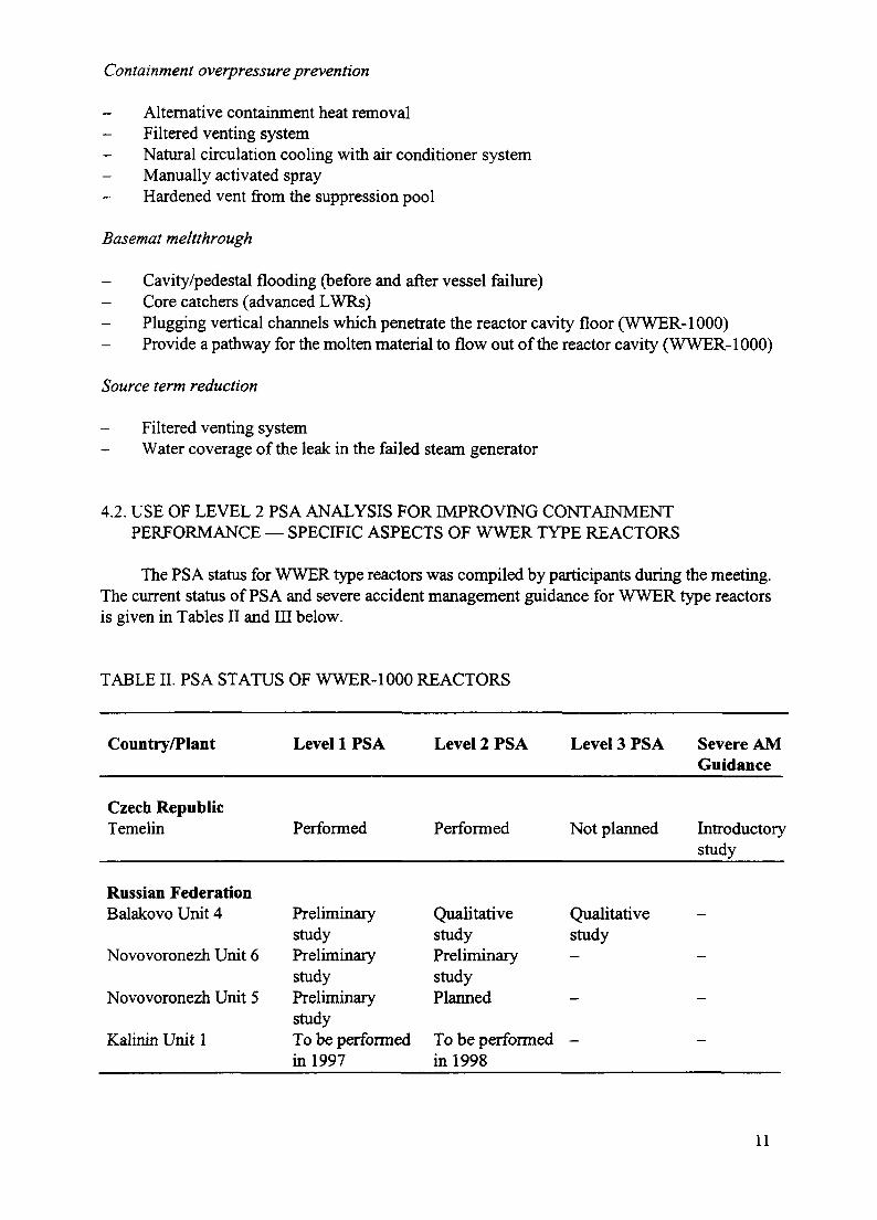
The PSA status for WWER type reactors was compiled by participants during the meeting.The current status of PSA and severe accident management guidance for WWER type reactorsis given in Tables n and in below.
TABLE II. PSA STATUS OF WWER-1000 REACTORS
Country/Plant
Czech RepublicTemelin
Russian FederationBalakovo Unit 4
Novovoronezh Unit 6
Novovoronezh Unit 5
Kalinin Unit 1
Level 1 PSA
Performed
PreliminarystudyPreliminarystudyPreliminarystudyTo be performedin 1997
Level 2 PSA Level 3 PSA
Performed Not planned
Qualitative Qualitativestudy studyPreliminary -studyPlanned -
To be performed -in 1998
Severe AMGuidance
Introductorystudy
-
-
-
-
11

TABLE III. PSA STATUS OF WWER-440 REACTORS
Country/Plant Level 1 PSA Level 2 PSA Level 3 PSA Severe AMGuidance
Russian FederationNovovoronezh Unit3&4Kola Unit 1Kola Unit 3&4
Preliminary -studyPerformed -To be performed -in 1998
SlovakiaJ.Bohunice V-l (230)
J.BohuniceV-2(213)
Mochovce (213)
Performedongoing revisionclose to finishPerformed
Started in 1996 -
Planned
Will start in 1997 -
Czech RepublicDukovany(213) Performed To be performed
in 1997Introductorystudy
Czech Republic
Probabilistic safety assessment and severe accident evaluation are not yet included in theCzech regulation. New rules, currently under preparation and soon to be implemented, willinclude PSA and severe accidents. Level 1 PSA has been carried out for both NPPs, Dukovany,WWER type 440/213, and Temelin, WWER type 1000. The Level 2 PSA for the Temelin NPPwas completed in 1996 and the one for Dukovany will be in 1997. Severe accident studies wereperformed during the last five years. Initially the STCP code was utilized, now MELCOR andCONTAIN are used. The preparation of accident management procedures has been initialized.
The approach of the regulatory organization is based on the United States NuclearRegulatory Commission (USNRC) generic letter for IPEs. For selected severe accidents there isthe requirement to prepare accident procedures or measures. The selection is done based on PSAresults, engineering studies and judgement and operational experience. After the elaboration ofthe severe accident measures and procedures, the specific sequences are re-evaluated.
The full scope Level 2 PSA study performed for the Temelin NPP resulted in theidentification of the severe accident sequences which are dominant regarding consequences forthe environment and population. The list of relevant severe accident scenarios based on the Level2 PSA study was presented for discussion and review. On the basis of this list, the proposal forfurther activities in this field was put forward:
12

- To carry out detailed analyses of the dominant scenarios with the MELCOR code;
- To utilize the results of these detailed MELCOR calculations for evaluation of the proposedsevere accident management measures;
To perform off-site emergency planning;
- To further substantiate the assumptions and data for the Level 2 PSA study.
The Level 2 PSA study for the Dukovany NPP is under development, currently theconstruction of GET and their quantification has been completed. The sequences with the highestrelevance were analysed with the MELCOR code. The results of these analyses show possibleways for improvements to the containment and containment systems.
Slovakia
A Level 2 PSA study has been started for the WWER-440/230 this year. The study will becarried out in co-operation with Nuclear Electric (UK), AEA Technology (UK) and two Slovakorganizations (VUJE and RELKO). The progress of this study is delayed at present because it wasnecessary to revise the Level 1 PSA study. Investigation of the boundary conditions for theconfinement are in progress at VUJE and the PDSs have been defined. The Level 2 PSA isconsidered to be very important for this type of plant because one of the most often commentedweaknesses of the WWER-440/230 is that the units do not have a full size containment.
The Level 2 PSA for the WWER-440/213 plant is planned in the near future for theBuhunice V-2 NPP. The Mochovce NPP is currently under construction. Start of operation isplanned for the end of 1998. The Level 1 PSA study should begin in 1997. Once Level 1 iscompleted, work on Level 2 PSA will commence.
Russian Federation
A qualitative Level 2 PSA study has been performed on the Balakovo Unit 4 NPP with thetechnical assistance of NNC (UK) and Belgatom (Belgium). Quantification of the consequencesof containment event sequences is planned using deterministic analyses performed with theFrench ESCADRE code.
The following stages have been completed:
- Level 1, 2 interface;
- Development of the containment event tree and allocation of release categories to end statesof GET;
- Containment probabilistic structural analysis using AB AQUS code and taking into accountmajor uncertainties;
- Containment penetration and leakage analysis using an EPRI procedure;
- Determination of provisional source terms for each release category and their comparisonwith those given in NUREG-1150.
13

The following steps should be performed to finalize the study:
- To complete the severe accident analysis;
To perform source term analysis;
To quantify all GET sequences for all PDSs based on results of severe accident andcontainment fragility analyses.
The analyses are intended to show the need for improving containment performance.
5. IMPORTANT ISSUES
Important problem areas and issues regarding Level 2 PSA were discussed at the meeting.The description of these issues follows the order given in the IAEA's Level 2 procedures [1].Issues which are specific to WWER type reactors and to channel type reactors are addressed inseparate paragraphs.
5.1. GENERAL ISSUES
5.1.1. Scope and objectives of a Level 2 PSA
It was pointed out that the scope of the Level 2 PSA should be as complete as possible,including for example a complete set of initiating events, both internal and external, and allrelevant plant operating states. A more comprehensive and complete assessment of humaninteractions should be considered in the Level 2 PSA.
Primary importance should be attached to prevention of severe accidents. Reducing theprobability of containment bypass scenarios and improvements to the ability of the containmentto withstand accident loads should receive particular attention. In addition, accident managementactivities should focus on the reduction of source terms, because they determine consequencesand plant risk.
5.1.2. Organization and project management
It was pointed out that the support from the plant operator for the Level 2 PSA tasks iscrucial. The requirements upon project organization and management for a Level 2 PSA differsignificantly from those of a Level 1 PSA. Therefore it is important that the benefits of the Level2 PSA be perceived by the plant operator. Furthermore, confidence in Level 2 PSA results mustbe established.
Technical and management interfaces for Level 2 PSA activities need to be defined in aparticularly careful way. This includes the interfaces with the Level 1 PSA group and tasks, aswell as with those of Level 3 if a Level 3 PSA is carried out.
5.1.3. Quality of the Level 2 PSA
A good Level 2 PSA quality is crucial for establishing confidence in the Level 2 PSAresults. This requires first that a formal quality assurance programme be established and made
14

effective for the Level 2 tasks. Such formal quality assurance programme includes items such asthe definition of Level 2 PSA organization and management and procedures for the technicaltasks to be carried out. Maturity and adequacy of approaches, codes, methods and data should bedemonstrated. Additionally, different levels of review are important to obtain a quality Level 2PSA.
5.1.4. Compilation of plant features, familiarization with the plant
Plant information used for Level 2 analyses should be as specific as possible. Therefore,the particularities of a specific containment should be known and taken into account whenperforming Level 2 analyses. Past analyses have shown that sometimes minor design andoperational features may significantly impact on results. Plant walkdowns are particularlyimportant for the Level 2 work. If the analysis is made for a plant in the design stage, assumptionsmay be necessary to perform the analysis, and should later be verified and revised, if necessary,by a detailed walkdown in the plant.
Analysts should have detailed knowledge of the plant. This is not a trivial requirementbecause analysts are often not directly affiliated with the plant. For example, the unknownexistence of a single drain at the bottom of the reactor cavity can invalidate the results ofextended analyses dealing with core concrete interactions.
5.1.5. Analysis of containment performance
Containment performance analysis determines the capacity of the containment and of itselements to withstand the various loads and conditions during accident sequences. This analysisshould be comprehensive and realistic by including all important elements and factors, such as:
- Specific design and features of the containment to be analysed;
Specific material properties;
Influences of surveillance, tests, inspections, maintenance, repairs and effects of ageing;Initial and boundary conditions;
- Status of containment elements depending on plant's operating conditions and initiating andconsequential events in accident sequences;
- Failure modes and the extent of failures;
Dependencies;
- Loads and phenomena impacting on the containment during accident sequences;
- Performance of containment systems and equipment during accident sequences;
- Categorization and characterization of leaks and ruptures and other assumptions;
- Failure criteria;
15

- Conservatisms used when information is limited or missing;
- Availability and transferability of information from experiments.
Particular care should be given to containment bypass scenarios and to the analysis ofcontainment isolation performance and reliability.
5.1.6. Accident progression analysis
It was pointed out during the meeting that the use of accident progression computer codesrequires extended experience in order to avoid non-physical results and 'user effects'. The userneeds to be aware of the code limitations in models and default values and specifications. Thecomputer codes should be quality assured and validated as far as possible, in particular for theirapplication to specific plant configurations and features.
Auxiliary and other plant buildings should be included in a realistic manner in the analysisif they have a potential to reduce the source terms. This corresponds to a comprehensive view ofthe concept of containment.
There was a general consensus of participants that accident progression codes and severeaccident phenomena models need further development and research. Special attention should begiven to code improvements for the long term phase of severe accidents and to their ability tomodel accident management measures. Specific severe accident phenomena which need furtherconsideration are the following:
- Steam explosion, in- and ex-vessel, small scale steam explosions;
Debris dispersion by small scale steam explosions, at vessel failure and debris-waterinteraction;
- Hydrogen deflagration and detonation;
- High pressure melt ejection;
Core-concrete interaction;
Direct containment heating.
There should be more activities for code validation and benchmarking of accidentprogression codes. More effort should be devoted to validate these codes as far as possible inorder to increase the confidence in Level 2 results.
5.1.7. Development and quantification of the Level 2 PSA model
There was a broad consensus among the meeting participants that human behaviour andconditions for human interactions which have to be assessed in a Level 2 PSA need moreattention and research. Human actions for accident management need to be supported byappropriate emergency procedures (including training, if implemented practically). Otherwisethere can be very little confidence in the success of such actions. Assessment of humaninteractions should involve a careful investigation of conditions and influence factors.
16

Environmental qualifications for I&C, other important equipment and equipment used foraccident management should be carefully evaluated. If expert judgment is used for bridgingmissing or limited knowledge or information it should be well structured, balanced anddocumented to establish confidence and traceability. Quantification of the models should beaccompanied by the assessment of uncertainties and sensitivities for key assumptions andparameters.
The limitations of the current way of modelling the logic of event sequences for Level 2PSA were discussed during the meeting. Today such modelling is usually done with logic eventtrees of various degrees of complexity. A majority of the participants declared that the presentmethodology is adequate for the purpose. However, for modelling long term sequences andsequences with complicated timing requirements, some participants pointed out that Markovianmodels might be more appropriate. Therefore, research in this area is recommended.
5.1.8. Uncertainty and sensitivity analysis
The performance of uncertainty and sensitivity studies is recommended for all Level 2 PSAstudies. The outcome of the Level 2 PSA analysis depends in many aspects on modellingassumptions. This kind of variability should be investigated with sensitivity analyses whichwould help to establish confidence in the results. There is a need for guidance in systematicuncertainty and sensitivity analyses. Also, the methodology for assessing variability in modelsneeds further development.
5.1.9. Interpretation of results
It was pointed out during the meeting that the interpretation of results has to include theresults of uncertainty and sensitivity analyses. Uncertainty and sensitivity analyses are crucial forestablishing confidence in the conclusions derived from the Level 2 PSA.
5.1.10. Issues related to the application of information and results
The uncertainty which exists for some aspects of Level 2 PSA is still a concern with respectto using the results in decision making. For the consideration of plant improvements and accidentmanagement actions and features, cost-benefit analysis can be performed and adverse effects ofaccident management actions and features should be considered. For the analysis of specificaccident management actions and features, the PSA model sometimes needs adaptation orextension and special dedicated supportive analysis. Guidance for the performance of this kindof assessment is needed. During the meeting the question was raised whether and what kind ofaccident management actions or features need to be considered if the risk of a plant is alreadylow. No comprehensive view on this aspect could be developed during the meeting.
5.2. WWER SPECIFIC ISSUES
5.2.1. WWER-1000
For WWER-1000 plants only two Level 2 PSA studies have been carried out to date on thefollowing two NPPs:
Balakovo NPP, Unit 4 (Russian Federation),Temelin NPP (Czech Republic).
17

Only a limited number of accident progression analyses have been performed for WWER-1000 plants. The Level 2 PS A work for Unit 4 of the Balakovo NPP considers several scenariosresulting from only one initiating event - a large LOCA. A full Level 2 PS A has been performedon the Temelin NPP. Similarly to the Balakovskaya NPP, only a limited number of accidentscenarios were analyzed by the Rez Nuclear Research Institute and utilized in the study. Otherrequired phenomenological information was obtained mainly from the literature (NUREG reports,other PSAs, IDCOR reports, etc.). Therefore, it is believed that the Level 2 PSA studies for theWWER-1000 plants haVe a significant level of uncertainty that can only be removed after moreresults from WWER-1000 specific analyses become available. Additionally, the results of theLevel 2 PSA for the Temelin NPP are influenced by significant conservatisms resulting from anumber of pessimistic assumptions used in the Level 1 part.
As a consequence, the two available Level 2 PSA studies should only be considered aspreliminary. Nevertheless, the studies helped to increase the understanding of the major strengthsand weaknesses of the containment, and allowed to pinpoint areas for more detailedinvestigations. Specific features of interest are the following:
- The containment bottom plate is located three levels above ground, the three levels inbetween are part of the non-hermetical auxiliary building.
The reactor cavity is surrounded by 50 ionization chamber tubes that are located in thecavity walls very close (ca. 15 cm) to the inner surface of the cavity. These tubes penetratethe whole thickness of the containment basemat to the non-hermetical room beneath thecontainment. The tubes represent a potential weakness regarding penetration of the basematby melted core material. In order to make reliable predictions, this item will need detailedinvestigation and analysis.
Analyses of the WWER pressure capacity performed for the Level 2 study show that thecontainment is robust and resistant to overpressure. With the exception of the specific basematfeature discussed above, it is comparable to other PWR containments. The following points werenoted regarding a refined estimation of the containment capacity:
Derivation of containment failure pressure should take into account all possible beyonddesign failure modes, i.e. catastrophic failure, failure of pressure boundary components(liner buckling or tearing, penetrations, insert plates, sumps, gaskets of airlocks etc.) withrespect to effects of creep, corrosion and ageing.
Uncertainty and randomness sources of corresponding containment fragility curves shouldbe clearly identified and may be based on generic information or take into account plantspecific information.
A deterministic check should be performed for components of the pressure boundary toconfirm their ability to withstand the ultimate pressure of global failure.
For cases when the yield or buckling limit is being approached, the development of aprobabilistic fragility curve is required.
The possibility of dependencies between events should be looked into, such as betweenpressure rise and spray header malfunction or polar crane derailment.
18

5.2.2. WWER-440 (both versions, 230 and 213)
The confinement of the WWER-440/230 is limited to hermetic rooms surrounding theprimary circuit and the steam generators. The free volume of the confinement is relatively small.An assessment of the confinement response would need investigation of particular features suchas overpressure capacity and an assessment of the locations and sizes of potential leaks. Theconfinement of the WWER-440/213 is equipped with a pressure suppression facility, the bubblercondenser. The free volume of the confinement is comparable with other PWRs. As for the440/230, an assessment of the confinement response would need investigation of the overpressurecapacity and the assessment of locations and sizes of potential leaks.
The main issues regarding analysis of confinement response for this reactor type are thefollowing:
Modelling of the confinement response with existing computer codes needs to take intoaccount the particular features of these plants. The appropriateness and the limitations ofthe models in these codes need to be carefully ascertained.
International knowledge and experience in this field are very limited.
5.3. SPECIFIC ISSUES FOR CHANNEL TYPE REACTORS
Two categories of issues for channel type reactors were identified during the meeting. Thereare many issues which are common to the general issues and shared with other types of plants.The following issues are specific for channel type reactors:
Level 1 sequence end states, and as a consequence also plant damage states are different,unique and considerably more complicated for channel type reactors as compared to vesseltype LWRs due to the different core design. Therefore, a different type of analysis isrequired to derive the PDSs for Level 2 PSA. An increased number of PDSs arises and theirdescription is more complex.
The study of accident progression is a key issue for the use of Level 2 PSA to evaluate andimprove containment performance for this type of reactor.
Accident progression in the core region and in the whole plant has significant particularitiesfor these reactor types. For PHWRs the time evolution of most of the severe accident scenariosis very slow due to the characteristic design features of the reactor. The most important designfeatures of PHWRs in that respect are the following:
large cooling capability of the moderator located around the fuel channels;
additional enclosure provided by the calandria and calandria vault with large amounts ofwater;
suppression pool and double containment in some designs.
While these specific design features may have a positive role in delaying and decreasingthe severity of severe accidents progression, they lead also to increased difficulties andcomplexity in modelling of phenomena and processes.
19

There is a number of severe accident phenomena, processes and items which need to bestudied in more detail for this type of plants, such as:
- moderator boiling;- cooling effect of calandria vault water;- core concrete interaction;- suppression pool below calandria (in some designs).
6. FINAL REMARKS
It was suggested that a comprehensive report and a database containing descriptions ofmeasures and features, envisaged to cope with severe accidents for different reactor types, bedeveloped. For groups entering the Level 2 PSA and the field of severe accidents it appears to bedifficult to obtain a systematic overview in this area.
It would be very useful to develop technical guidance on how to assess in practice accidentmanagement measures and features with PSA and other supporting studies. It would be also ofinterest to have procedures on how to develop design prescriptions for equipment and systemsenvisaged to cope with severe accidents.
Systematic and meaningful uncertainty and sensitivity analyses along with theirinterpretation is considered to be a difficult area which would require guidance. Uncertainty andsensitivity studies are recognized to be essential in Level 2 PSA to demonstrate the robustnessof the Level 2 models and to establish confidence in the results. Guidance would be urgentlyrequired, in particular regarding sensitivity studies to deal with uncertainties from models andmodelling assumptions. A further area which would need more attention is human reliabilityassessment for human interactions in Level 2 PSA.
Information exchange and feedback from other PSA teams working in the Level 2 PSA areaare essential.
Due to the complexity of accident progression codes, organization of benchmark exercisesand code workshops would be highly desirable.
Meeting discussions showed that the topic 'how safe is safe enough' remains veryimportant and that guidance in this area is required, in particular regarding plant improvementsthrough accident management.
WWER type reactors
Level 2 work for WWER type reactors is still in its beginning stages. It would be highlydesirable that specialized meetings and comparison workshops be organized on this topic.Confinement performance analysis for the WWER type 440 (both 230 and 213) appears to beparticularly difficult. The work done in this area is very limited, especially in the areas ofstructural analysis and analysis of leak locations and sizes. This information is a necessaryprerequisite for a reasonably detailed Level 2 study.
20

Channel type reactors
It has become increasingly evident that detailed deterministic analysis of DBAs and beyonddesign basis accidents reveal considerable insights into channel reactor response to variousaccident conditions. These analyses can also help in better characterizing outstandingphenomenological uncertainties, improved EOPs and accident management strategies, includingpotential risk beneficial accident mitigative backfits. The analyses will also contribute to anincreased understanding of the performance of the containment or accident localization system.
The PHWR group represented at the meeting formulated the following three specificrecommendations:
(1) Modelling of severe accident phenomena for PHWRs should be a key point for furtheractivities and the exchange of information for this type of plant.
(2) The proper functioning of equipment should be considered in Level 2 PS A, in particularwith regard to its capability to work during severe accidents. The qualification ofequipment may be upgraded, if necessary, from the design basis accident range to theconditions given during beyond design basis accidents.
(3) Level 2 PS A benchmark exercises would be especially helpful for the development of themethodologies for this type of NPP.
REFERENCE
[1] INTERNATIONAL ATOMIC ENERGY AGENCY, Procedures for ConductingProbabilistic Safety Assessments of Nuclear Power Plants (Level 2), Safety Series No. SO-P-8, IAEA, Vienna (1995).
21

LIST OF ABBREVIATIONS
AC alternating currentAECL Atomic Energy of Canada LimitedALS accident localization systemAM accident managementASDV atmospheric steam discharge valveATWS anticipated transient without scramBDBA beyond design basis accidentBWR boiling water reactorCANDU Canada deuterium-uranium (reactor)CCFP conditional containment failure probabilityCDF core damage frequencyCET containment event treeCSDVS condenser steam discharge valvesDCH direct containment heatingDET decomposition event treeECCS emergency core cooling systemESF engineered safety featuresFP fission productHEPA high efficiency particulate air (filter)HPCS high pressure core sprayHPME high pressure melt ejectionI&C instrumentation and controlIPE individual plant examinationLBLOCA loss of coolant accident following a large pipe breakLOCA loss of coolant accidentLWR light water reactorMDL maximum design limitsMSLB main steam line breakMSLBA main steam line break accidentMUW make-up waterNPP nuclear power plantPC primary containmentPCCDS primary containment controlled discharge systemPCFPB primary containment filtration and pumpback systemPDS plant damage statePHTS primary heat transport systemPHWR pressurized heavy water reactorPSA probabilistic safety assessmentPSC probabilistic safety criteriaPWR pressurized water reactorRBMK light water cooled, graphite moderated channel type reactorRC release categoryRCIC reactor core isolation coolingRCP reactor coolant pumpRCS reactor coolant systemRHR residual heat removalRPT reactor pump tripRPV reactor pressure vessel
22

RSG recirculating steam generatorSC secondary containmentSCRPS secondary containment recirculation and purge systemSDM safety design matrixSDCS shutdown cooling systemSGTR steam generator tube ruptureSLB steam line breakSOL safe operation limitsSTCP source term code packageTSG technical support guidelinesWWER water moderated, water cooled energy reactor
NEXT PAGE(S) I „left BLANK I 23

Annex
PAPERS PRESENTED AT THETECHNICAL COMMITTEE MEETING

XAQ846Q17A PROPOSAL FOR ACCIDENT MANAGEMENT AMSOHOSOPTIMIZATION BASED ON THE STUDY OFACCIDENT SEQUENCE ANALYSIS FOR A BWR
M. SOBAJIMAJapan Atomic Energy Research Institute,Tokai-mura, Ibaraki-ken,Japan
Abstract
The paper describes a proposal for accident management optimization based on the study of accidentsequence and source term analyses for a BWR. In Japan, accident management measures are to beimplemented in all LWRs by the year 2000 in accordance with the recommendation of the regulatoryorganization and based on the PSAs carried out by the utilities. Source terms were evaluated by the JapanAtomic Energy Research Institute (JAERJ) with the THALES code for all BWR sequences in which loss ofdecay heat removal resulted in the largest release. Identification of the priority and importance of accidentmanagement measures was carried out for the sequences with larger risk contributions. Considerations foroptimizing emergency operation guides are believed to be essential for risk reduction.
I. Introduction
Accident management (AM) measures are to be implemented in all light water power reactors in Japanby the year 2000 [1]. Since the examination of accident management was requested to the utilities by theregulatory authorities, the Nuclear Safety Commission (NSC) and the Ministry of International Trade andIndustry (M1T1), each utility planned their strategy of implementing accident management in their powerreactors [2], [3]. These measures were proposed on the basis of their probabilistic safety assessments (PSAs).They were approved after reviews by the regulatory bodies to be appropriate as a whole finally in November1995.
JAERI is performing PSA studies for general purposes which include the examination of accidentmanagement. Analytical codes for evaluating core damage sequences are being developed and applied topower reactors for studying the consequences of severe accident sequences. Source term analysis with theTHALES/ART [4] and THALES-2 [5] codes developed for this purpose is available, as source term modelsfor release, transportation, deposition and revaporization of radioactive materials are incorporated in them.Since these codes run relatively fast, overall calculation of many sequences is feasible. Based on comparisonof various sequences, numerous insights and knowledge concerning categorization of similar sequences couldbe gamed.
With this knowledge and based on the study on the AM measures proposed by the utilities, the authorproposes some important aspects which are desired to be incorporated in the emergency plant operationprocedure guide for optimizing the effect of each AM measure.
II. Preceding Work
Kajimoto et al. [6] performed severe accident sequence analysis of a BWR and grouped the varioussequences according to the scenario of pressure vessel failure and containment failure due to overpressure.They clarified the effects of core melt relocation, coupling of thermal-hydraulics and fission product (FP)vaporization, and containment failure location on the release fraction of Csl to the environment for a varietyof sequences shown in Table 1 as sensitivity studies by using the THALES/ART (THALES-2) code.
The major findings of the work can be summarized as follows:
(1) The analyzed sequences initiated by transients and LOCA are basically categorized in 5 groupsaccording to the similarity of the scenario from core damage to containment failure.
27

(2) The released mass of Csl also exhibits similar behavior in each group. It is affected by the meltrelocation modes in which the core melt is once trapped at the core support plate at the bottom of thecore or not. If the melt experiences high temperature there due to lack of coolant, the major part ofFPs is released into the reactor coolant system (RCS) and deposits in the RCS, more or less,depending on the time duration in the sequence.
(3) Melt having not previously experienced high temperature may later release major amounts of FPsduring the process to containment failure. This could result in larger source term release into theenvironment. An example of FP release in transient sequences is as given in Fig. 1 which showslarger release for such sequence groups having shorter FP deposition time like the TW groups namedhere Groups A and B, and the TC Group E.
(4) The effect of containment failure location on source term release is also significant as shown in Fig.2 in which drywell space and wetwell liquid space failures with no water scrubbing effect showrelatively large source terms.
(5) When thermal-hydraulics and FP revaporization are coupled in the code model, the revaporization ofFPs in the reactor coolant system (RCS) during the containment depressurization process increasesthe source term to the environment by a factor of 10 at maximum compared with the source termwithout revaporization.
Watanabe et al. [7] performed further sequence analysis for the study of containment failure modes.They regrouped all significant accident sequences into 8 groups including interfacing system LOCA andreactor pressure vessel (RPV) rupture, and separated the loss of containment heat removal group intolong-term and short-term as summarized in Table 2.
They obtained the conditional containment failure probabilities (CCFP) for various failure modes, forfour separate accident progression stages in each sequence group and clarified the dominant containmentfailure modes and stages for each sequence group as summarized in Table 2. The dominant failure modeswere mostly over-pressurization and over-temperature in this study. However, the dominating stage wasdifferent group by group. For example, containment failure due to overpressurization dominantly occurs inthe 'pre-stage for core-melt' in Group 3 with loss of long-term containment heat removal, whereascontainment failure occurs in the 'long-term progression stage' in Group 7 with loss of short-term containmentheat removal. Though they also proposed mitigative measures by the use of conventional systems as shownin the table, these measures now should be replaced by the AM measures planned lately.
III. Discussions
The author reviewed the AM measures proposed by the utilities in the light of the correspondence withthe 8 groups proposed in the previous work by Watanabe et al. and gave some consideration for optimizingthose measures in timing and conditions of activation based on the above analytical results and otherknowledge obtained through various experiments and analyses of severe accidents.
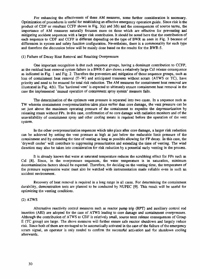
For a representative BWR-5 with Mark-II containment [ 1], [2] Table 3 summarizes the relation amongeach fundamental safety function, accident sequences contributing to core damage frequency (CDF) andcontainment failure probability and AM measures which are currently adopted and to be implemented togetherwith the AM measures already implemented. The corresponding sequence groups Gl through G8 in theprevious study are also indicated in the column of 'accident sequence' of this table. It can be confirmed thatall significant sequence groups correspond to either of the individual AM measures in the table except for theinterfacing system LOCA group, Gl which has a negligibly small contribution to CDF. Over-pressurizationand over-heating scenarios of the containment which were dominant in most of the sequence groups in Table2, are prevented or mitigated by the adopted AM measures such as 'alternative reactivity control', 'alternativewater injection to reactor and containment', 'drywell cooler' or 'hardened vent'. Thus, all sequence groupscan be covered by any of the AM measures already implemented and those adopted this time. The level ofdefence in depth for the core, pressure vessel and containment will be significantly increased by implementingall the AM measures.
28

Tl
£1 m o *""* o T^ ro -» 33 JL o o U) o' S o ex <D W o CO o c -1 o n> CD 3 \J ""*• o
_L CO
001
'i
— • C
O _L
l.c °
O n
3 s
9,H
_x
^
fD O
°3
"-2
, _,
< O
oCD
t/)
K>
Z3.
—
^
O-^
_i
Oo
Acc
iden
t S
eque
nces
3jO
O"1
0T
T'5
OO
^O
O"^
^D
OO
'OT
®®
O^
O^
JQ
OT
Q
S S| I *p|S|
C-S
><
<§
<
l< —
— 3
——
3 k
- 5 —
4s S
——
S —
— 4
1 c
'c '
c
' c
' c
';T3
"O
T
3
XI
XJ
>
mo
o
o
;
o •
^ ~*
ta
'•
'. C
D O
J o
*»J
S o
»
o o
o3 3
D
— —
o
• •
'it?
o*
ra
*
*
J
t/»
O
r
——
——
——
^
00
00
00
0o
o;
00
0*
*
^
/
!.
. .
0
00
00
00
°o
5" } r* o *o o i fi } 1 rtH i X W. c" (P o ex •8 •1 § 5- a
I cr 1 r o o ^ 5* VI
VI O i Si i. r+ S y o i.S. c cr 1»^ 8 i? V
I O o* •0 8 CA V) C
%
l§ 8' o a
v> VI O -+> I * ! < .T £ v> O O*
•a v> c 8 1-1 VI
•O 1-1 &5
PS
.
c" S g o" VI 3 §i
< EL G> < i" VI O 6 o* •a i rt ^2 i 3
hrj ^
w b
Cl
v>
8 £ II 3 G G
to
i—
S S
VI
VI
s, s,
n<5-
^^ n> c 3 8 W
)*O
I "i R G £ vl O 6 er •o 8 c o* CO ^ 3
to
^^
^^
^^
^^
^H
Hd
H H
H H
H H
oo
w w
w ro
G G
2
™<
X G
HH
HH
HH
HH
H0
0
W W
OO
OO
j£
GG
G
G G
G
3
^
0 G
W G
G
O5
GO
GO
00
GO
(/5
G
O
0 G
G W
G G
< X
_
< ^
'oo
ow
'wo
oo
o':
?G
GC
G
GG
^
Transient(other than IORV)
iw
r**
i ft^
i<s w 2 «• g
-
11
H 1 r 8
CP o. a on I i.
For enhancing the effectiveness of these AM measures, some further consideration is necessary.Optimization of procedures is useful for establishing an effective emergency operation guide. Since risk is theproduct of CDF or resultant CCFP shown in Fig. 3(a) and 3(b) and the consequences of source terms, theimportance of AM measures naturally focusses more on those which are effective for preventing andmitigating accident sequences with a larger risk contribution. It should be noted here that the contribution ofeach sequence to CDF and CCFP is different depending on the type of BWR as seen in Fig. 3 because ofdifferences in system and safety function configuration. Nevertheless, there is a commonality for each typeand therefore the discussion below will be mainly done based on the results for the BWR-5.
(1) Failure of Decay Heat Removal and Resulting Overpressure
One important recognition is that such sequence groups, having a dominant contribution to CCFP,as the residual heat removal system failure in a BWR-5 also shows a relatively large Csl release consequenceas indicated in Fig. 1 and Fig. 2. Therefore the prevention and mitigation of those sequence groups, such asloss of containment heat removal (T—W) and anticipated transients without scram (ATWS or TC), havepriority and need to be ensured for total risk reduction. The AM measures for containment heat removal areillustrated in Fig. 4(b). The 'hardened vent' is expected to ultimately ensure containment heat removal in thecase the implemented 'manual operation of containment spray system' measure fails.
The determination of the optimum vent pressure is separated into two cases. In a sequence such asTW wherein containment overpressurization takes place earlier than core damage, the vent pressure can beset just above the maximum operating pressure of the containment to expedite the depressurization byreleasing steam without FPs. In this case, confirmation of no core damage with radiation monitors and of theunavailability of containment spray and other cooling means is required before the operation of the ventsystem.
In the other overpressurization sequences which take place after core damage, a larger risk reductioncan be achieved by setting the vent pressure as high as just below the endurable limit pressure of thecontainment and by extending the time of venting as long as possible allowing for FP decay. In this case, the'drywell cooler' will contribute to suppressing pressurization and extending the time of venting. The winddirection may also be taken into consideration for risk reduction by a potential early venting in the process.
It is already known that water at saturated temperature reduces the scrubbing effect for FPs such asCsl [8]. Since, in the overpressure sequences, the water temperature is in saturation, minimumdecontamination factors should be expected. Therefore, for deciding on the venting time, the temperature ofthe pressure suppression water must also be watched with instrumentation made reliable even in such anaccident environment.
Recovery of heat removal is required in a long range in all cases. For determining the containmentdurability, demonstration tests are planned to be conducted by NUPEC [9]. This result will be useful foroptimizing the venting conditions.
(2) ATWS
Alternative reactivity control measures such as reactor pump trip (RPT) and auxiliary control rodinsertion (ARI) are adopted for the case of ATWS leading to core damage and containment overpressure.Although the contribution of ATWS to CDF is relatively small, source term release consequences of GroupE (TC group) are large. The above measures will further ensure safe reactor shutdown and largely reducerisk. Since both of them are envisaged to be automatically activated in the case of the failure of the emergencyscram signal, an operator is only needed to confirm the successful activation and for shutdown coolingafterwards.
30

C/)0)OCCD
C0)•D-
TlQUVTPQUVTQUVTiQUXTPOUXTQUXTDPUTlOUTBUTBPTiBTBTlOUVlWTlQUWTPQUViWTPQUWTQUViWTQUWTCTlQUiWTiQWTiWTPQUiWTPQWTPWTQUiWTOWrw
t_L."""! —— ' ' ""H ' ' "1Tnl —— ' ' ' '""I ' ' """I —— r-rrmiT,4 0 «
4 O •4 0 •
4 O •Group C * o •
>"" ~
4 O 44 O •4 0 •4 O •r~ * o •
Group D * 4 ° * 0 .— f- 4 O •t * 0 •
„' * o •Group B 4 04I 4 0 *Y 4 04
Group E * • ° _ .>r— • • o
PCV Failure Location ** °——————————————————————— • o• yi: Drywell Gas Space * o
Group A 4 -ft: Weiwell Gas Space ~ "o
L o -p: Weiwell Liquid Space *• oMbIOCUIiOri MO(JU ll 4 « O
. , , . . , , ! , , , ,,,.J , . .,,,,.1 , , . ..,,,1 . 7 . ,.,"l , .......
10 -G 10'; 10-" 10 -3 10 -2 10 -1
Source Term of Csl (-)(Fraction of Core Inventory)
Fig. 2 Effect of Containment Failure Location on Source Term of Csl
(3) Loss-of-Electric Power Supply and Resulting Direct Containment Heating
In addition to the supply of high voltage electric power from the adjacent plant with a cross-tie alreadyimplemented, the 'supply of low voltage power' from the adjacent plant with another cross-tie and 'supplyof power from D/G for MFCS' are adopted, as the BWR-5 is provided with a special D/G for HPCS. Theoperator who connects the cross-tie needs to confirm the activation of the D/G of the adjacent plant or of theD/G for HPCS for supplying power. The 'supply of low voltage power' from the adjacent plant will be usedto activate D/Gs in case of battery system failure in the accident plant. All these measures for terminatingSBO sequences, by establishing the emergency guide and training of the operators, will contribute to eliminatethe DCH sequence in Fig. 3(b) and the large source term release of Group D (TB sequences).
(4) Failure of Water Injection or Depressurization and Resulting Over-heating
The contribution of those sequence groups initiated by failure of water injection and depressurizationof RPV to CDF is relatively small. The consequential source term release mass is also the smallest of all thegroups. However, the probability and consequence of a steam explosion still have a large uncertainty. If itoccurs violently in the pressure vessel or in the containment, the source term mass release out of thecontainment drywell may significantly increase as can be seen in Fig. 2 for Group C.
It is already known that dropping of the melt in water at relatively high pressure (> IMPa) or witha temperature near saturation does not cause significant steam explosion [10]. Therefore, water massdistribution and the pressure and temperature of the water are crucial for the prediction of steam explosionoccurrence. Melt relocation and water conditions must be carefully monitored with required instruments toavoid a steam explosion. When water injection is required for melt cooling both in the pressure vessel andcontainment, spraying water on the melt is more desirable than filling plenty of water in a place beneath themelt where it finally slumps (see Fig.4(a)). Effective melt cooling conditions also need to be establishedthrough research and reflected in the emergency guide to prevent the melt spreading on pedestal floor anddirectly attacking the containment shell as well as the concrete floor.
31

K)
ATA/SBO Others
BWR3
ATWS
ATWS
DWR4
j-OCA.olhers
T
DWR5 ABWR
Figure 3(a) leveM PSA results [2]
DCSE Others Others
BWR3
QT othersBWR4
OB
BWR5 ABWR
Figure 3(b) level-1.5 PSA results [2]
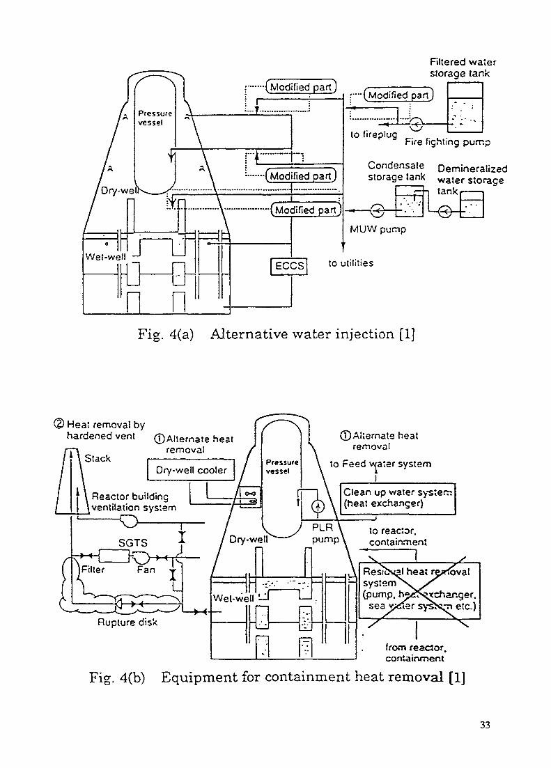
•——(Modified partj
-I—••-(Modified part)
Filtered waterstorage tank
(Modified part)
.'•••• (Modified part]
to fireplug „ u.Fire fighting pump
Condensate Demineralizedstorage tank water s«orage
tank
MUVV pump
to utilities
Fig. 4(a) Alternative water injection [1]
) Heat removal byhardened vent 0 Alternate heat
removalStack
©Alternate heatremoval
to Feed water system
Clean up water system(heat exchanger)
Reactor buildingventilation system
to reactor,containment
from reacior.containment
Fig. 4(b) Equipment for containment heat removal [1]
33
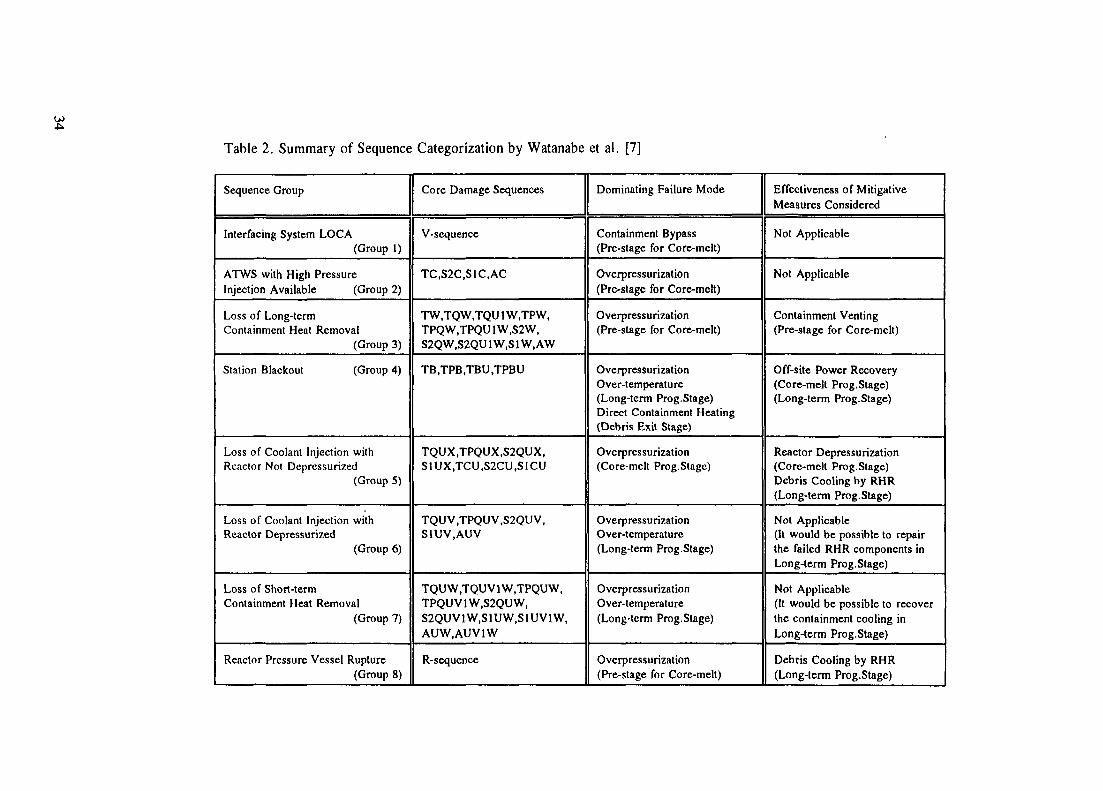
Table 2. Summary of Sequence Categorization by Watanabe et al. [7]
Sequence Group
Interfacing System LOCA(Group 1)
ATWS with High PressureInjection Available (Group 2)
Loss of Long-termContainment Heat Removal
(Group 3)
Station Blackout (Group 4)
Loss of Coolant Injection withReactor Not Depressurized
(Group 5)
Loss of Coolant Injection withReactor Depressurized
(Group 6)
Loss of Short-termContainment Heat Removal
(Group 7)
Reactor Pressure Vessel Rupture(Group 8)
Core Damage Sequences
V-sequence
TC,S2C,S1C,AC
TW.TQW.TQU 1 W.TPW,TPQW,TPQU1W,S2W,S2QW.S2QU 1 W,S 1 W, AW
TB,TPB,TBU,TPBU
TQUX.TPQUX.S2QUX,S1UX,TCU,S2CU,S1CU
TQU V ,TPQU V ,S2QU V ,S1UV.AUV
TQUW.TQU V 1 W.TPQUW,TPQUV1W.S2QUW,S2QUV1W.S1UW.S1UV1W,AUW.AUV1W
R-sequence
Dominating Failure Mode
Containment Bypass(Pre-stage for Core-melt)
Overpressurization(Pro-stage for Core-melt)
Overpressurization(Pre-stage for Core-melt)
OverpressurizationOver-temperature(Long-term Prog. Stage)Direct Containment Heating(Debris Exit Stage)
Overpressurization(Core-melt Prog. Stage)
OverpressurizationOver-temperature(Long-term Prog. Stage)
OverpressurizationOver-temperature(Long-term Prog. Stage)
Ovcrpressurization(Pre-stage for Core-melt)
Effectiveness of MitigativeMeasures Considered
Not Applicable
Not Applicable
Containment Venting(Pre-stage for Core-melt)
Off-site Power Recovery(Core-melt Prog.Stage)(Long-term Prog.Stage)
Reactor Depressurization(Core-melt Prog.Stage)Debris Cooling by RHR(Long-term Prog.Stage)
Not Applicable(It would be possible to repairthe failed RHR components inLong-term Prog.Stage)
Not Applicable(It would be possible to recoverthe containment cooling inLong-term Prog.Stage)
Debris Cooling by RHR(Long-term Prog.Stage)
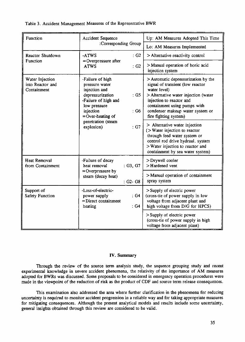
Table 3. Accident Management Measures of the Representative BWR
Function Accident SequencerCorresponding Group
Up: AM Measures Adopted This Time
Lo: AM Measures Implemented
Reactor ShutdownFunction
-ATWS : G2= Overpressure afterATWS : G2
> Alternative reactivity control
> Manual operation of boric acidinjection system
Water Injectioninto Reactor andContainment
-Failure of highpressure waterinjection anddepressurization : G5
-Failure of high andlow pressureinjection : G6=Over-heating ofpenetration (steamexplosion) : G7
> Automatic depressurization by thesignal of transient (low reactorwater level)> Alternative water injection (waterinjection to reactor andcontainment using pumps withcondenser makeup water system orfire fighting system)
> Alternative water injection(> Water injection to reactorthrough feed water system orcontrol rod drive hydraul. system> Water injection to reactor andcontainment by sea water system)
Heat Removalfrom Containment
-Failure of decayheat removal=Overpressure bysteam (decay heat)
G3, G7
G2-G8
> Drywell cooler> Hardened vent
> Manual operation of containmentspray system
Support ofSafety Function
-Loss-of-electric-power supply : G4=Direct containmentheating : G4
> Supply of electric power(cross-tie of power supply in lowvoltage from adjacent plant andhigh voltage from D/G for HPCS)
> Supply of electric power(cross-tie of power supply in highvoltage from adjacent plant)
IV. Summary
Through the review of the source term analysis study, the sequence grouping study and recentexperimental knowledge in severe accident phenomena, the relativity of the importance of AM measuresadopted for BWRs was discussed. Some proposals to be considered in emergency operation procedures weremade in the viewpoint of the reduction of risk as the product of CDF and source term release consequences.
This examination also addressed the area where further clarification in the phenomena for reducinguncertainty is required to monitor accident progression in a reliable way and for taking appropriate measuresfor mitigating consequences. Although the present analytical models and results include some uncertainty,general insights obtained through this review are considered to be valid.
35

References
[1] Sobajima, M., et al., "Current Status of the Implementation Plan of Accident Management to PowerPlants", J. Atom. Ener. Soc. Japan Vol. 37(5) (1995) (in Japanese)
[2] Miyata, K., et al., "Accident Management for BWR in Japan", 3rd Int. Conf. Nucl. Eng.(ICONE-3) Kyoto, Japan, April (1995)
[3] Ohtani, M,, et al, "Severe Accident Management Strategies for PWR Plants in Japan", ditto, (1995)[4] Muramatsu, K., et al., "Sensitivity Study on BWR Source Terms Using the THALES/ART and
REMOVAL Codes", Int. Conf. Thermal Reac. Saf. (NUCSAFE 88), Avignon, France (1988)[5] Kajimoto, M., et al., "Development of THALES-2, A Computer Code for Coupled Thermal-
Hydraulics and Fission Product Transport Analyses for Severe Accident at LWRs and Its Applicationto Analysis of Fission Product Revaporization Phenomena", Int. Mtg Safety of Thermal Reac.Portland, USA (1991)
[6] Kajimoto, M., et al., "Analysis of Source Term Uncertainty Issues for LWRs", Int. Conf.Probabilistic Safety Assessment and Management (PSAM-II), San Diego, USA (1994)
[7] Watanabe, N,, et al,," Categorization of Core-Damage Sequences by Containment Event Tree Analysisfor Boiling Water Reactor with Mark-II Containment", 3rd Int. Conf. on Containment Des. and Op.Oct. (1994)
[8] Oehlberg, R.N., et al., "Experimental Results from the Electric Power Research Institute (EPRI)Program on the Source Term", Proc. American Power Conf., vol. 46'. April (1984)
[9] Matsumoto, T., et al., "Plan on Test to Failure of a Steel, a Pre-stressed Concrete and a ReinforcedConcrete Containment Vessel Model", 13th Int. Conf. Structural Mech. in Reac. Technol. (SMIRT13), Porto Alegre, Brazil Aug. (1995)
[10] Yamano, N., et al., "Phenomenological Studies on Melt-Coolant Interactions in the ALPHAProgram', Nucl. Eng. Des. 155 pp369-389 (1995)
36
XA9846918PARAMETRIC MODEL TO ESTIMATE CONTAINMENTLOADS FOLLOWING AN EX-VESSEL STEAM SPIKE
R. LOPEZ, J. HERNANDEZ, A. HUERTAComision Nacional de Seguridad
Nuclear y Salvaguardias,Mexico City,Mexico
Abstract
This paper describes the use of a relatively simple parametric model to estimatecontainment loads following an ex-vessel steam spike. The study was motivated becauseseveral PS As have identified containment loads accompanying reactor vessel failure as amajor contributor to early containment failure. The paper includes a detailed description ofthe simple but physically sound parametric model which was adopted to estimatecontainment loads following a steam spike into the reactor cavity.
1. INTRODUCTION
Several Probabilistic Risk Assessments (PRA) have identified containment loadsaccompanying reactor vessel failure as a mayor contributor of early containment failureduring severe accidents. Relatively simple, parametric models have been developedto which allow the PRA analyst to evaluate the range of conditions under which thecontainment loads may be an important contributor to the containment failure. In thispaper a set of calculations utilizing those parametric models to estimate containmentloads for Laguna Verde Nuclear Power Plant are presented, as well as a discussion ofits utilization in the PRA.
2. DESCRIPTION
The Laguna Verde Nuclear Power Plant (LVNPP) Unit 1 is a 1931 Mwt BWR-5 boilingwater reactor, designed and supplied by the General Electric Company with a Mark IIcontainment.
The containment design employs a steel lined reinforce concrete structure utilizing theover-and-under pressure suppression concept. The pressure suppression conceptconsist of a dp/well over a pressure suppression chamber or wetwell. The drywell andwetwell are separate for a concrete floor (diaphragm floor) which is perforated by 68downcomer pipes to drive the steam released during a Loss Of Coolant Accident into thesuppression pool. To suppress the pressure in the containment during an accident, twotrains of sprays are located in the containment. In the event of failure of sprays tosuppress the pressure, the containment can be vented. To reduce the potential of asevere hydrogen combustion event the containment is inertized with nitrogen.
37

3. PSA Requirements
Several Probabilistic Risk Assessments (PRA's) have identified containment loadsaccompanying reactor vessel failure as a major contributor of containment failure duringpostulated severe accidents[1]. One potential contributor to those loads is aphenomenon referred to as "steam spike ". A Steam spike is a rapid (but non-explosive) generation of steam that results from the interaction of molten core debris witha pool of water.
In the reactor cavity of the Laguna Verde Nuclear Power Plant (LVNPP) are located thecontrol rod drive mechanism along wiht two pools to storage the floor and equipmentdrains ( 3.96 m3 of storage capacity each). The liquid -collected in those pools are smallleakages of the system components during normal operation. In the case of acontainment sprays actuation, there would be a significant amount of water in the abovementioned pools. Therefore ,if the bottom of the reactor vessel fails, the molten coredebris will fall down into the reactor cavity and a steam spike phenomena would beexpected.
The PRA team have to analyse, the likelihood that the steam spike phenomena occursfor each sequence related with reactor vessel breach. Analytical methods for estimatingcontainment loads have focused on the development of mechanistic models forintegration in large computer codes such as CONTAIN[2]. However, the application ofquite sophisticated mechanistic models requires an impractical investment on time andfinancial resources to analyse hundreds of accident sequences of the containment eventtree. The methodology utilized in the NUREG-1150[1J lets the PRA analyst to handleparameters and probabilities for the containment event tree heads and this flexibilitythen allows the analysis of several accident progression pathways for a fixed set of initialcondition included in the definition of the plant damage state (i,e. Is highly uncertain theamount of zircaloy oxided before vessel rupture, so that a set of possible answers isrequired). In order to provide a practical tool, we propose to use a relatively simple butphysically sound model to represent the mass and energy addition to the containmentfollowing core meltdown and breach of reactor vessel.
4. MODEL DESCRIPTION
Models for steam spike and direct containment heating developed by Mark T. Leonard[3]are particularly convenient for the present analysis .The models are simple, physicallysound and were developed for Boiling Water Reactors.
The model considers three steps:
1. Molten core material emerges from the reactor vessel and falsl into a pool of waterthat covers the drywell floor, for LVNPP we have to consider the equipment drainscollector sumps. The rate, composition and temperature at which melt would leavethe reactor vessel, are highly uncertain and several possibilities were examinedparametrically. A wide range in values for the following initial conditions wereconsidered:
• total mass of molten material interacting with water.• initial temperature of the melt.• fraction of zirconium mass that was oxidized in-vessel.
38

2. When the melt reaches the water pool, rapid steam generation facilitates mixing offragmented melt particles with water. The extent of melt-coolant mixing is limited bythe rate at which steam can escape the water pool. Unmixed melt mass is assumedto fall to the bottom of the water pool and not be quenched.
3. Molten debris transfers latent and sensible heat to the water pool. Oxidation ofmolten zirconium/steel metal by sorrounding water consumes steam but produceshydrogen in equal molar proportion. The reactions are also highly exothermic, addingto the melt sensible heat that can be transferred to the water.
The maximum extent of heat transfer to the water and chemical energy addition to themelt from oxidation reactions over the time frame of interest are rate limited. In thecase of heat transfer to water, heat losses from fragmented debris (melt) particles arelimited by film boiling at the particle surface. The Production of chemical energy islimited by oxidation kinetics for metalic debris constituents.
As the debris mass falls down into the pool, it breaks apart into smaller particles whichmay subdivide further as steam produced at their surfaces flowing upward toward thesurface -of the pool. Melt fragmentation continues until the rate of steam productionprecludes further debris-water contact (i.e., the remaing water is fluidized andtransported away from unfragmented debris) or the falling debris mass reaches thebottom of the pool.
Following reference [3] the limit to melt-coolant mixing is defiened as a coolantfluidization (countercurrent flow) limit. The maximum mass of molten debris that can bemixed with the coolant is estimated as
where
md.™. maximum (mixed) debris mass in coolant poolpf, pr liquid and vapor (water) density, respectivelyDmit characteristic diameter of mixed debris particlesq"^ heat flux at the particle surfaceA^ latent heat of vaporization for waterA^ drywell floor area (pool cross-sectional area)vx superficial critical vapor velocity (i.e., steam velocity that will fluidize entering
liquid coolant)
The total extent of (metal) particle oxidation during the melt/coolant interaction is treatedparametrically (i.e. specified ahead of time). The total mass of molten debris poured intothe coolant pool is also specified as a parametric variable.
The energy of reaction corresponding to the specified extent of melt oxidation is addedto the enthalpy of the debris before calculating the maximum mass of melt that can bemixed with the coolant. However, the mass of oxidized melt is assumed to be limitedby the mass of melt that can be mixed with the coolant.The maximum mass of melt thatcan be mixed with coolant is a function of debris temperature. Therefore, an interativesolution is required.
39

1. an estimatation of the fraction of the poured melt mass that mixes with the coolantof the pool (the remainder is assumed to sink to the bottom of the pool uncoiled).
2. the film boiling heat flux at the surface of a melt particle of characteristic dimension
mix'
The total amount of energy transferred to the coolant pool is then simply the product ofthe heat flux at the particle surface (q"^} and the total surface area represented by themixed mass of melt
where Ar is the time interval in which the steam generation produces an increase indrywell pressure (1 s).
The total number of debris particles of characteristic size uma is given by
(3)
where
m mass of melt poured into coolant poolpourmaximum mass of debris that can mix with the coolant pool
Assuming the pool is initially at the saturation temperature, the mass of water vaporizedcan be estimated. However, as discussed earlier, some of the steam is consumed in theoxidation of a (predefined) fraction of the metallic melt. Two moles of hydrogen areproduced for every mole of steam consumed in oxidizing Zircaloy, and (using iron torepresent the reactions of stainless steel) one mole of hydrogen is produced per moleof steam consumed in oxidizing steel. If the fraction of metal constituents in the moltenpour oxidized ex-vessel is defined as /or and the fraction of poured mass that is Zircaloyis defined as f.r, then the total number of moles of vapor generated is
/ j _ y f N (4)
" 'where
's tne molecular weight of water.
The initial number of moles in the drywell atmosphere (NRCl) can be estimate from theideal gas law:
P> V KC
40

where
pt pressure of the drywell at vessel breachVRC. total free volume of the drywell
RV universal gas constantT, temperature of the drywell atmosphere at vessel breach
Assuming an adiabatic (isothermal) pressure transient, the incremental pressure due tosteam spike and ratio of peak to initial pressure are
VKC
and
respectively,
5. RESULTS
In order to show the estimates obtained with the above parametric model, we presenttwo sets of calculations. In the first set, we assume
- A particle diameter of 10 mm- 70% of the zirconium was oxidized in-vessel- 1700 K of initial melt temperature.
The second set assumes a particle diameter of 100 mm with the same overallassumption as in the first set.
Figure 1 shows that the smaller particle size precludes faster the premixing phasebecause as the particle size becomes smaller the surface area for heat transfer becomehigher, therefore the steam generation increase impeding the interaction between moltencore debris and coolant.
Figure 2 and 3 show the tendency to reach an increase pressure limit independentof the molten core debris poured. The limit is bounded by the maximum mixed massand the transient time. The steam generated beyond the transient time (1s) is assumedto be fully condensed. Figure 2 shows, in the 10% and 30% cases that the pressureincreases, this is due to an increase in melt temperature, and therefore the pressurereaches its maximum, as the melt temperature fits the temperature at which the 10%and 30% of the mass is mixed, as showned in the figure 1. Figure 3 shows the samebehaviour as the figure 2 but the profile remains unchanged due to that the fact that themaximum mixed mass is not reached .
41

20 CC - —
18 OC ————V__ 1600 —
x^ K 00 —ni i 2 00 —O "u ^ 10 OC-
8 00
6 OC •
t- 00-
2 CO-
0 CD-•7oc : 18CC " S C O 20CO 2 1 0 CINTlAL ML.T TEM-ERATURE (K)
FIGURE 1. Maximum mixed mass for a 10 and 100mm.
* 100mmo 10mm
90 '/• 01 2-
Cmx = 100 mm
• COSc.c_
- 006
1 C03-
CC170C -75C 1800 1850 1900 1950 2000 2050 7
TEMPERATURE (K)
FIGURE 2. Ratio of peak to initial pressure for the 10, 30 and 90% of the total metalic mass
42

1 015-————————————————————————————Dmix = 10 mm
012-
1 009 —9C ; 30 % V 10 7
§ :——————-Q- ' '
1 006—————————————————
1 001700 1750 1800 1850 1900 19SO 2000 2Cbu / : ,MLLT TEMPERATURi (K)
FIGURE 3. Ratio of peak to initial pressure for the 10, 30 and 90% of the total metalic mass.
6. CONCLUSIONS
The relatively simple but physically sound model adopted here allows the PSA analystto perform speedy parametric (sensivity) studies of the contribution of steam spikecontainment loads.
The model described in this paper is not intentded to replace mechanistic models forsteam spike, rather, as a tool to provide rough estimates.
REFERENCES
[1] "Severe Accident Risks: An Assessment for Five U.S. Nuclear Power Plants - FinalSummary Report", NUREG-1150, Vol. 2, U.S. Nuclear Regulatory Commission(Dec. 1990).
[2] K.D. Bergeron, "User's Manual for CONTAIN 1.0, A computer Code for SevereNuclear Reactor Accident Containment Analysis", NUREG/CR-4085.SAND84-1204,Sandia National Laboratories (May 1985).
[3] Mark T. Leonard, "Rough Estimates of Severe Accident Containment LoadsAccompanying Vessel Breach in Boiling Water Reactor", Nuclear Technology, Vol108 (Dec 1994).
NEXT PAGE(S) I ^left BLANK I 43
XA9846919STATE OF LEVEL 2 ANALYSES AND SEVERE ACCIDENTMANAGEMENT IN SPANISH NUCLEAR POWER PLANTS
R. OTEROIBERDROLA,Madrid, Spain
Abstract
The state of the PSA/IPE studies in the Spanish NPPs is presented in this report, as•well as the plans to implement the severe accident management strategy both in the SpanishBWRs and PWRS. First, the Spanish LWRs are introduced, and the scope of the IPEanalyses required by the Spanish Regulatory Commission (CSN) is given. The generaloverview is completed with the current degree of development for the IPE studies in eachplant.
In the second pan the methods and tools are shown which are used by the Spanishplants to develop their Level 2 analysis. The different strategies for severe accidentmanagement adopted by the BWRs and PWRs in Spain are also outlined. The sources andimplementation of the Severe Accident Guidelines (SAG) are described.
More detail is given in the following chapters to the containment analysis of Trillo(PWR, KWU design) and Cofrentes (BWR/6, GE design) NPPs, whose development is beingcarried out by IBERDROLA. The analysis which has been performed up to date for Trillois limited to the Plant Damage State (PDS) definition. However, the main phenomenachallenging its containment performance have been identified, and they are summarized here.The Level 2 analysis for Cofrentes is comparatively more developed. The main phenomenaand the key equipment affecting its containment behaviour are presented. Finally theconclusions of this report are elaborated.
I.- STATE OF PSA/IPE DEVELOPMENT IN SPAIN
There are several types of LWR in Spain: from BWRs, General Electric design withMark-I and Mark-Ill containments, to PWRs of Westinghouse (6 units, one of them with1 loop) and KWU design (see Fig.2.1). The Spanish Regulatory Commission (CSN)started to require the Utilities an increasingly extended scope for their PSAs, beginningin 1984 by demanding a Level-1 scope to the first one (Sla Ma de Garona), and requiringa full IPE (Level-1, Level-2, IPEEE. and off-power states) to C.N. Trillo-1, the lastLWR put into operation in Spain (see Fig.2.1). CSN's plans are to request a full scopeof the IPEs in each plant, extending their previous analyses.
The current state of the Level-2 analyses in the different commercial LWRs in Spain isthe following:
BWRs• CN Cofrentes (GE, Mark-Ill) Level 2 under development• CN Garona (GE, Mark-I) Level 2 being started, to be finished in 1997
45

UPDATINGON SCOPE?
OTHE ;RN/>L
OTHER SOURCES OFRADIOACTIVITY
OFF-POWER STATES (SHUTDOWNAND LOW POWER)
SEISMIC EVENTS
ICVU / (SOURCEtil M; AI POWCfi/
- J J' t'.'.' I,' i CVALUA 110"
11 in tin it.
INlLlvNALKOCiDiNC
CONTAINMENTSlSTEMb
INTERNALTIRf
i rvn iA I f'UWIK
STA. MaGAROfJAUWK-OL
Mork 1460 MWe
84
MAR 84
SET 85
FEB 87
P lix>i$siyVyVx%x£vx>
ALMARAZ1 te IIPWR-W3 loops
JUL 86
APR 87
MAR 87
NOV 89
APR 90
W//M
.
ASCO1 A II
I'WR-W3 loops
930 MWe
JUN 87
JAN 89
DIG 88
SET 92
%%%%
mm
COFRENTES
1 BWR-CEMark III
1 9tO MWe
FEB 88 '
FEB 89
FEB 89
JUL 90
MAR 95 (prsv.)
JOSE CABRERA
PWR-W1 loop
160 MWe
JUL 89
JUN 90
NOV 90
JUL 93
;$mm
VANDEULOS II
PWR-W3 loops
992 MWe
OCT 90
JUL 91
SET 91
OCT 94
TRILLO I
IPWP-KWU3 loc-ps
1041 MW'
JUL 91
JUL 92
SET 93
STA. MoGARORA
BWR-CE I•160 MWe 1
ENE 95
l$£&&&&&^NON REQUESTEDDEVELOPED
V//////ANON REQUESTED
W INISHED
1 1REQUESTED
CSNREQUIREMENT
"PROJECT PLAN"APPROVAL
PSA STARTING
PSArev. 0ENDING
PSA rev 1(including CSN's
comments)
FIG. 2.1 PSAs IN SPAIN NPPsSCOPES

PWRs• CN Almaraz (2 units; Westinghouse-3 loops) Level 2 prepared, although not
requested yet• CN Vandellos-2 (1 unit; Westinghouse-3 loops) Level 2 under CSN revision• AN Asco (2 units; Westinghouse-3 loops) Level 2 not started• CN Jose Cabrera (1 unit; Westinghouse-1 loop) Level 2 under CSN revision• CN Trillo (1 unit; KWU-3 loops) Level 2 under preparation
2.- GENERAL TRENDS IN SPANISH NPP
2.1.- METHODS AND TOOLS
The methodology requested by the CSN to be used in the Individual Plant Examinationof the Spanish LWRs is the well known collected in the US-NRC Generic Letter 88-20.All the Spanish Utilities performing Level 2 analyses have followed the methodconsisting in a PSA plus a Containment Performance Analysis, as advised in Appendix1 of that Generic Letter.
MAAP3 is the tool being used by all the plants to simulate the severe accidentprogression and to perform the sensitivity analyses on uncertain phenomena. However,some of the plants have developed models and expertise with the MAAP4 andCONTAIN codes, although these codes are planned to be used only in particular cases ifneed exists. MAAP4 models are being prepared by some plants as a support tool to theimplementation of the Severe Accident Management guides.
A general policy of the plants is to use the results of their Containment Analysis tojustify the non installation of new Containment equipment. Nevertheless, some of themhad got some equipment installed before starting their analysis, mainly because ofanticipation on previous American BWR experience (see §4 below).
2.2.- BWRs SEVERE ACCIDENT MANAGEMENT
The Owners Group of Spanish BWRs has decided to implement into their organizationsand procedures a common strategy for the management of severe accidents. Thatstrategy is based on the one of its American counterpart. It is collected into the AccidentManagement Guidance (AMG). The AMG includes the Emergency ProcedureGuidelines (EPG) and the Severe Accident Guidelines (SAG). The SAGs are conceivedas a continuation of the EPGs, and changes are introduced to smooth the transition fromone guide into another. The Technical Support Guidelines (TSG) are also merged intothe AMG to provide engineering assistance to the emergency organization. Finally, theAMG includes the criteria to assign the responsibility of given actions out of the ControlRoom.
The Containment Analysis of the Spanish BWRs has been oriented from the beginningto training. The results of all the simulations performed for the IPE are included into alibrary. Suitable tools will be available to retrieve from this library a selected scenario,with the explanations of the situation and the evolution of its plant conditions. TheSpanish BWROG is considering also the convenience of simulation tools for severeaccident training.
47
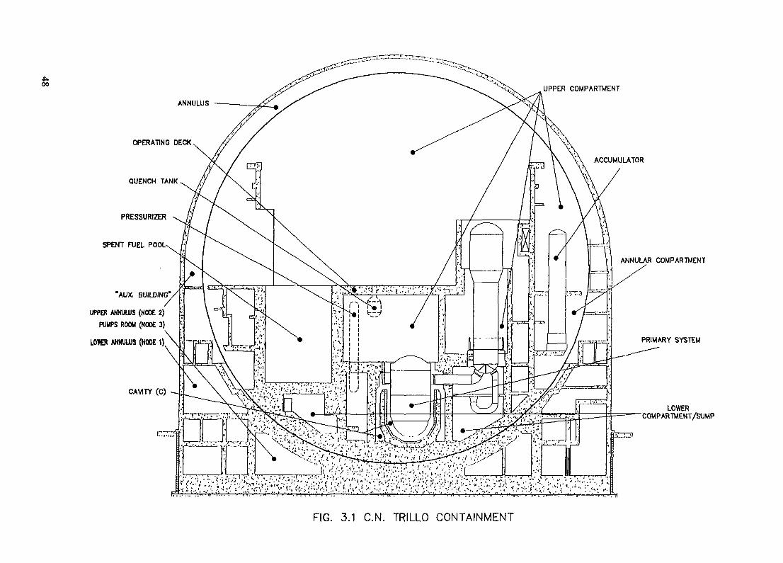
ANNULUS
OPERATING DECK
QUENCH TANK
PRESSURIZER
SPENT FUEL POOL-
"AUX. BUILDING"
UPPER ANNULUS (NODE 2)PUMPS ROOM (NODE 3)
LOWER ANNUUJS (NODE 1)
CAVITY (C)
UPPER COMPARTMENT
ACCUMULATOR
. . . . . ^ _^ • ' — — > r .^$£^
ANNULAR COMPARTMENT
PRIMARY SYSTEM
LOWER"COMPARTMENT/SUMP
FIG. 3.1 C.N. TRILLO CONTAINMENT

2.3.- PWRs SEVERE ACCIDENT MANAGEMENT
The Spanish PWR of Westinghouse design have taken as their basis for severe accidentmanagement the generic SAGs developed by the Westinghouse Owners Group (WOG).Contrarily to the BWROG's approach, in the WOG's the SAGs are clearly separatedfrom the EPGs, and they are only managed by the Technical Support Center (TSC)
To date, the results of the Level 2 analyses available in some of these PWRs show thatcontainment venting is not needed.
3.- TRILLO NPP CONTAINMENT ANALYSIS
C.Trillo-1 is a PWR of KWU design. Its thermal power is 3015 Mwt. The RCS has 3loops with 3+1 safeguards trains for the safety injection and the emergency feedwatersystems. The design of the safety systems with 4 redundancies stems from theapplication of the single failure criterion and the consideration of 1 train being repaired.
The containment analysis for Trillo has not been started yet. Currently its Level 1 isbeing updated with plant modifications implemented recently. However, the Level-l/Level-2 Interface has been analyzed and preliminary Plant Damage States (PDSs)have been defined.
The containment for Trillo, as a KWU design, presents some particularities whencompared to more extended PWR designs (see Fig.3.1). It consists on a steel spherestanding on a concrete bowl. This external bowl supports both the sphere and an innerbowl which bears all the containment structures (walls and equipment). The spacebetween the sphere and the concrete containment (the so called "Annular Building")hosts the safety injection system (including its borated water tanks) and the nuclearcomponent cooling system. The steel sphere is designed to stand a LBLOCA incoincidence with a MSLB, so that its design pressure is rather high. The spent fuel poolis located inside containment close to the refuel pool.
The Reactor cavity is dry and tight. For such a tight cavity, the German Risk Study(DRS) assumes that in sequences with high-pressure Vessel failure, containment wouldfail as a result of the Vessel "rocket" displacement (Ref.l).
Preliminary studies for sequences with medium-pressure Vessel failure show that thefraction of core debris dispersal out of the cavity may be important because of itsfluidification and entrainment in such a tight cavity.
Another characteristic is that the containment is partly compartmentalized, although thecompartments are rather open. Moreover, there is no spray nor fan-coolers within it forDBA, so that steam inertization is thought to play an important role in Hydrogenphenomena in severe accidents.
If core debris is not frozen, the generation of non-condensible gas due to CCI is veryreduced because of the basaltic composition of the basemat concrete. The steadypressurization of the containment in such a situation is rather due to the steaming of
49

water in the sump, because of the decay power of the fission products aerosols depositedin it. However, this pressurization process is very slow. The basemat depth is close to 7m, so that its melt-through is also a long-term process.
4.- COFRENTES NPP CONTAINMENT ANALYSIS
CN Cofrentes is a BWR/6, with a Mark-Ill containment, designed by General Electric.Its nominal power is 2951 MWt. It has three electric divisions, with a safeguard dieselper division. Its commercial operation began on May 1985.
Currently, the Level 2 studies are being performed in Cofrentes. In the Level 1/Level 2Interface the resulting PDSs have been merged into 16 KPDSs. None of the identifiedKPDS shows characteristics that could result into large releases in the short term. Themost significant KPDS involve transients which ended up in intact containment withboth low and high pressure; low pressure critical ATWS with containment failed, andlow pressure SBO sequences with intact containment. The Containment Event Trees(CET) and Decomposition Event Trees (DET) are being developed for these KPDSs.Typically, two different CETs are to be used, one for V sequences and the second for theother PDSs.
The containment capability is being determined by a detailed structural analysis onultimate failure pressure and associated fragility curves. Its dynamic response will beconsidered only in a simplified way. Key points in the assessment of the containmentintegrity are:• capability of the pedestal to withstand large dynamic pressures, high temperatures
and corium penetrations up to 8 feet;• drywell behaviour on underpressures caused by HI explosions in the wetwell• containment quasisteady pressurization.The containment failure mode is dependent on corium coolability: if corium is notcoolable, the pedestal would be challenged by high temperatures and concretepenetration and containment would be pressurized by the non-condensible gasesstemming from CCI; if corium is coolable the vapor generation would pressurize thecontainment, if heat removal is not available, and challenge its integrity.
From the studies developed up to date for Level 2. the main components forcontainment performance in severe accidents have been identified. These maincomponents, which have an outstanding role in the containment performance ofCofrentes, are the following:• H2 igniters. They are located in the containment out of the drywell. There are 2 trains
of igniters, one of them ac/dc supplied. They were not installed by design, but ratheras an anticipation based on previous American BWR experience;
• containment venting without filtering. It was originally installed as a way to controlpressure in emergency conditions (operator action in the EOPs);
• drywell vacuum-breakers. They were installed to avoid loss of coolant in thesuppression pool. Their stuck opening would result in a bypass of the suppressionpool as a fission product (FP) scrubber;
• containment spray. Even if its heat exchanger were not available, it would have animportant effect on FP scrubbing;
• late injection to the RPV or the Pedestal by the Fire Protection pumps.
50

5.- CONCLUSIONS
The overview of the PSA/IPE studies in Spain has been shown. The plants are followingand developing sound and well-known methodology and tools. The studies are welloriented towards, on one hand, the understanding of the key phenomena and plantresponse in severe accident sequences and, on the other hand, the development ofaccident management guides.
REFERENCES
1.- NRC 2241, German Risk Study on Nuclear Power Plants, Phase B. Feb. 1990
NEXT PAQE(S)left BLANK I 51

XA9846920ANALYSIS OF FEED WATER ACCIDENTS WITH THEMELCOR CODE FOR THE WWER-440/213 NPP
G.L. HORVATHInstitute for Electrical Power Research,Budapest, Hungary
Abstract
This paper contains a description of the Level 2 PS A related studies in Hungary for the PaksNPP. A Level 1 PSA has been performed for the Paks Unit 3 in the framework of the AGNESproject which is an overall safety reassessment project for this plant. The current PSA topics in workare shutdown PSA and human reliability. Also limited Level 2 PSA studies were performed for theAGNES project. The analytical tools available for the Level 2 work are STCP, CONTAIN,MELCOR, RELAP-SCDAP, and MAAP. Most of these codes are running at VEIK1. Goodexperience is available for STCP, CONTAIN and MELCOR, and currently experience is beinggained for MAAP and RELAP-SCDAP. Still more experience is needed for all the codes.
1. INTRODUCTION
Severe accident studies in Hungary started in VEIKI in 1988 when the Source TermCode Package (STCP) was adapted to VVER-440 reactors with the help of the IAEA(permitted by US NRC). After several initial studies the STCP was used extensively for theAGNES Project [1]. Since the time the AGNES project was completed, a new, much moredeveloped and versatile code, the MELCOR code was adapted for the analysis to eliminate thelimitations built in into the STCP. This presentation summarizes the latest results andexperience with the MELCOR code.
2. INPUT DEVELOPMENT
The VVER-440 input deck has been installed on the IBM_RISC_6000 workstation ofVEIKI. A comprehensive set of plots has been set-up to evaluate the computed results. Theinput developed by the help of the IAEA (RER/91004) was used as a starting point. The wholeinput deck has been re-structured and re-assembled and adapted to the MELCOR 1.8.3version. Steady-state conditions have been obtained by imposing time independent volumeconditions in the steam generator (SG) and pressurizer. Steady-state plant parameter valueshave been re-introduced to the input to obtain steady-state in a shorter time. The steady-stateobtained is close to normal operating conditions. The code keeps this obtained steady-state well.The nodalization scheme of the primary and containment side is given in Figs. 1 and 2.
The following problems have been resolved:
Primary circuit flow-path junction opening heights were adjusted to obtain "smooth" leveldecrease in the reactor vessel (that is avoid level decrease in the core before most of the upperplenum (UP) gets empty). Momentum exchange length parameters have been introduced.Primary loop cold- and hotleg flowpath junction elevations have been changed to model loopseal clearings correctly.
Pressurizer (PRZ) heaters switch-off setpoints on low level in PRZ have been corrected. Alsothe PRZ pressure operated relief valves (PORV) setpoints have been corrected according tothe VEIKI report 21.11.104-2.
53
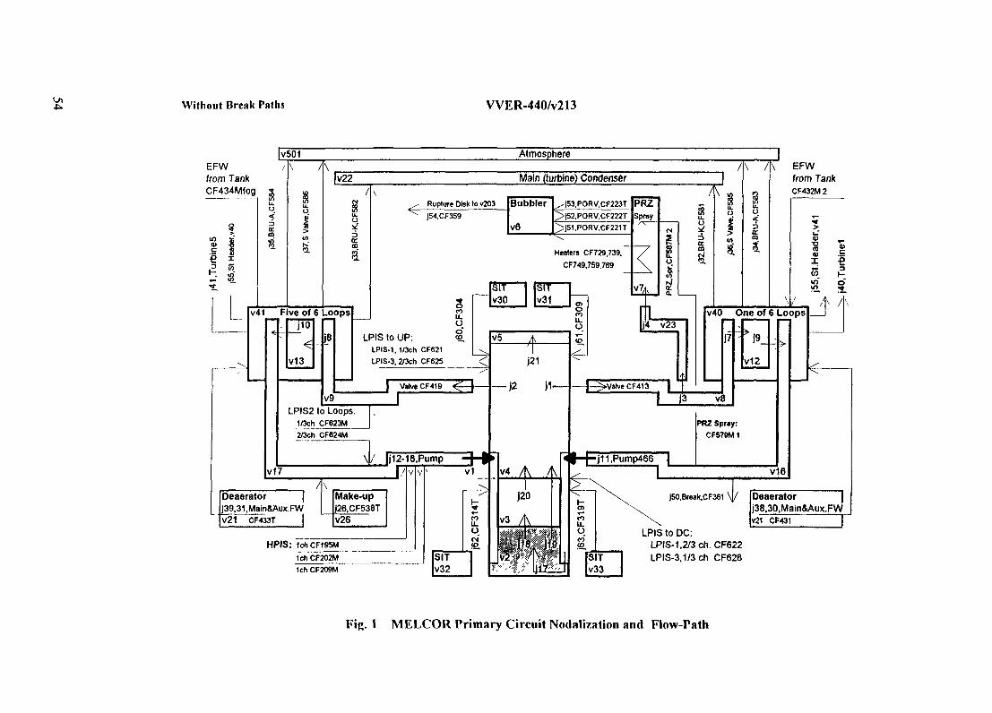
Without Break Paths VVER-440/v213
EFWfrom TankCF434Mfog 5———— - - —I Siu.o
[yS01
ina>s
I<na
K.ffi
/\
Atmosphere
[v22
a
v41 Five of 6 Loops
I10
<v13
J8
Main (turbine) Condenser
^ Rupture Disk (o v203 Bub"^ J54.CF359
V6
blef ^|53,PORV,CF223T>|52,PORV,CF222T>|51,PORV,CF221T
Healers CF729.739,CF749,759,769
snu.HSIT
V30SITv31
§<O
PR2Spray
r<c ——
IV?A
n
A
LPIS to UP:LPIS-1, 1/3ch CF621LPIS-3, 2/3ch CF625
O<0
oijfcc.m
V9J Valve CF419
|V5 ,f
J21
—— ]2 ]1-
LPIS2 to Loops.1/3ch CF623M
J
2/3ch CF624M
|4 V23
——|—^Valve CF418 |
oI
/\ A
%u.O
EFWfrom TankCF432M2
_tt> _I.5
v40 One of 6 Loops
R " * )9_
v12
» <3 v8
Deaeratorj39,31,Main&Aux,FWV21 CF433T
PRZ Spray:CFS78M 1
v16
|50.Break.CF361T
HPIS: 1chCF195M1ch CF202MIch CF209M
LPIS to DC:LPIS-1,2/3 ch. CF622LPIS-3,1/3ch CF626
|
o"
/ \
Deaerator |j38.30.Main&Aux.FWV21 CF431 T
Fig. 1 MELCOR Primary Circuit Nodalization and Flow-Path

Incl. Primary Circ. Cont. Breaks VVER-440/v213
Reactor Flail (operational Rooms)
Cv301 A FI241
E-6
Fig. 2 MELCOR Containment Nodalization and Flow-Paths

Hydro-accumulator's wall to containment has been provided with convective heat transferboundary conditions (and increased heat transfer coefficient) to avoid temperature conditionin their atmosphere being out-of-the-range of validity of MELCOR equations.
Main Coolant Pump (MCP) models have been corrected by introducing a MCP trip signal unit(PUMPTRIP.3IN file) handling the technological signals leading to MCP trip. (Pump trips aredriven now only by pressure, loss-of-electric-power and manual trip signals. Certain kind ofpump trips lead to SCRAM.)
Primary Circuit Breaks are introduced as valves activated after an initial steady-state run in therestart input of the MELCOR (MELIN) input file.
The SCRAM SIGNALS model has been corrected. (Now any SG level decrease below -0.4mresults in SCRAM).
The CORE package input has been adapted to MELCOR 1.8.3(dT/dz model). Debris surfacearea of Lower Head (LH) penetrations (CORPEN card Variable: ASPN) has been taken to bea small number to avoid penetrations, not existing in the VVER-440s Lhead.
On Secondary Circuit side new models for Main Feed Water, Auxiliary Feedwater, EmergencyFeed water and Turbine models have been introduced. Heat transfer to secondary side has beensolved with 5 separate heat structures along the height of the SGs. This model provides acorrelation of the heat transfer with the level in SG on both primary and secondary side.
The Containment Bubbler Tower Trays model has been simplified to avoid excessive calculationburden but retain accuracy. (Trays downcomer CV216 has been removed, and a directhorizontal flow-path to trays has been introduced with junction elevations reflecting the waterlock opening and the back-flow of water from trays.) The new model has been checkedincluding the check-valves from trays to air-locks and from trays to back to tower.
The Passive Spray model from trays of the bubbler condenser has been corrected. (Watersupply to Passive Spray source (CV212=space below trays) has been provided as a flow-path.)
The Cavity package has been re-activated to calculate core-concrete interaction with simplifiedgeometry.
The BURning and Radionuclide (RN) package has been activated.
In PRZ spray, Passive Sprays, SG Emergency Feed Water models instead of previous erroneousversion mass and enthalpy sources have been specified.
The High Pressure (BPIS) Low Pressure (LPIS) injection parts of Emergency Core Cooling(ECC) and the Containment Sprays systems have been reviewed, corrected and modifiedincluding several new features. The new features are the heat removal calculation in the Sprayand ECC heat exchangers and a containment sump model.
3. CALCULATING ACCIDENT SEQUENCES
The sequences calculated started from normal operating conditions (steady-state).
3.1. Loss-of-Coolant Accident (d=100mm)
A severe nuclear accident initiated by a single ended pipe break of d = 100 mm assumedto be in the lowest point of the cold-leg and accompanied with total loss of electric power(including diesel generators) has been analyzed.
56

Calculation was proceeded up to 7200 minutes (432000 s) without RN package and upto 625 minutes (37500 s) with RN package. Bottom head failure happened at 8340 s.
3.2. Total Loss-of-Feedwater Accident
3.2.1. Sequence definition
Results of the PSA Level-1 studies performed in the frame of the AGNES project [1]showed that in case of the VVER-440/213 nuclear power plant at the PAKS site, one of thebiggest contributors to the core damage frequency is the severe nuclear accident initiated by theloss of (main, auxiliary and emergency) feedwater due to instantaneous full cross section breakof the main feedwater header which also breaks the emergency feedwater header situated closeto the previous one. After the initiating event the reactor scram stops the chain reaction but theloss of secondary heat sink leads to core damage.
The electric power will be available during the whole process but the make-up water(charging water) and the active ECC can not discharge due to the high pressure in the primarysystem. The accumulators can start only after the vessel failure. The containment spray systemis available during the whole process.
It was assumed that the check valves between the SG and main feedwater header areclosing very quickly so that no significant secondary coolant loss to containment happens.
3.2.2. Sequence timing
The main events and timings are the following:
the main, auxiliary and emergency FW stops at time 0.0s;loss of FW results in rapid decrease of FW in SGs which causes a SCRAM signal (at55s) when the level is 0.4 m below the nominal;dry-out of the SGs causes deterioration of the heat-exchange in the SGs which in turnstarts the primary circuit pressure to rise and initiates the discharge of the primarycoolant to the bubbler tank of the pressurizer;the membrane of the bubbler tank breaks to the containment at a pressure of 1.52MPain the bubbler vessel and the discharge of the primary coolant to the containment startsfrom 12797 s;the Main Coolant pumps stop due to the signal "Containment Pressure > 0.11 MPa" at13891 s;the core heat-up and melting starts when the water level in the reactor vessel decreasesbelow the top of the core at 20000 s;the release of fission products from the gas volume of the fuel cladding (gap release) toprimary circuit happens during 21124-23378 s;failure of the core support plate in the 4 radial rings used happens in the time intervalof 28301 -53184 s;hydroaccumulators start to charge water to reactor only after the reactor failure at 91198s;the whole process has been calculated up to 6000 min.
3.2.3. Sequence major findings
The major conclusions are as follows:
during the high pressure vessel failure a nearly 4 MPa pressure spike develops in thereactor cavity, that may challenge the containment integrity;
57

retention of volatile fission products in the primary circuit after the reactor vessel failureis relatively small due to high temperatures in the primary circuit. At the same timeheat-up of the hot-leg and its subsequent failure may change the course of events. Highpressure vessel failure may be avoided and a loss-of-coolant (LOCA) like sequence maydevelop. For final conclusions more detailed (structural response type) analysis would beneeded;for most of the fission product (FP) classes (except Te and Ce classes) release from thefuel during in-vessel melting phase is the most dominating;release from primary circuit to containment is relatively low during the in-vessel meltingphase for most of the FP classes. A high intensity source appears at the reactor vessellower head failure, when the FP vapors and aerosols (floating in the vessel) get released.For FP classes (e.g. Te) where the ex-vessel release is more important (or if the releaseof volatile FP was not finished during in-vessel phase) another rise in containment FPconcentration was observed;at the end of calculations (after 6000 min) most of the volatile Xe, Csl, Cs, Te classes gotreleased to the containment. The release to the containment of the other FP classes wassmall. In particular release of the Ba, Mo, Cd, Sn classes from the fuel was relativelyhigh but most of this release was retained by the core volume or by the primary circuit.Nuclides in FP classes of Ru, Ce, La, U almost entirely remained in the fuel. Only asmall fraction of the Ru class nuclides appeared in the primary circuit;most of the FP radionuclides at the end of calculations are in the SG-box containing therelease place and in the bubbler tower containing the corridor connecting the SG-box tothe bubbler tower;release of the FPs (except Xe) from containment is smaller than the previouslycalculated maximum due to the operation of the containment spray system. The releasefrom containment for Cs and Csl is 0.032 and 0.055 % of initial core inventoryrespectively. A similar release from containment was experienced in case of Te (0.0865%). The total Cs release (including Cs and Csl classes) is 0.0371%;FP distribution after 6000 minutes is given in Table 1. according to MELCORcalculations. FP distribution for the same conditions calculated by STCP are given inTable 2. The largest difference found was the higher release of volatiles from the primarycircuit calculated by MELCOR which is attributed to higher temperatures on the primarycircuit calculated by MELCOR.
Table 1. FP radionuclide distribution in a WER-440 plant after 6000 min according toMELCOR calculations in percent of initial core inventory for LOFW sequence. (Nocredit to retention in secondary confinement is given.)
NuclideClass
1235678910111216
In-Fuel
Xe 3.42E-08Cs 3.79E-07Ba 70.60Te 27.07Ru 98.83Mo 83.22Ce 99.77La 99.92U 99.94Cd 41.74Sn 40.96Csl 0.35
In PrimaryCircuit
0.1710.6826.763.181.1616.600.02860.0630.055756.7256.7811.10
In-Containment
72.5989.292.6469.660.01090.180.200.01372920.00811.542.2688.50
Released fromcontainment
27.240.0320.00210.08652.55E-065.32E-050.00011.55E-051.17E-050.00210.00360.055
58

Table 2. FP radionuclide distribution in a WER-440 plant after 6000 min according to STCPcalculations in percent of initial core inventory for a sequence similar to LOFW. (Nocredit to retention in secondary confinement is given.)
NuclideClass
1235678910111216
In-Fuel
Xe 0Cs 0Ba 75.21Te 26.79Ru 100.00MoCe 99.86La 98,02UCdSnCsl 0
In PrimaryCircuit
0.0590.115.8361.930.0007
00.00014
8687
In-Containment
82.359.8818.8711.170.000096
0.141.98
12.12
Released fromcontainment%17.60.00670.070.061.8E-06
0.000549.0E-04
0.0074
Abbreviations
ECCLPISLOFWHPISSGFPPRZHAUPLHAGNES
Emergency Core Cooling SystemLow Pressure Injection SystemLoss of Feedwater (accident)High Pressure Injection SystemSteam GeneratorFission ProductPressurizerHydroaccumulatorUpper PlenumLower HeadAdvanced General and New Evaluation of Safety (of the Paks NPP)
REFERENCES
[1] AGNES PROJECT: Safety Assessment of the PAKS Nuclear Power Plant, ExecutiveSummary, Oct. 1994, KFKI, Budapest, Hungary
NEXT PAGE(S)left BLANK 59

XA9846921OVERVIEW AND CURRENT STATE OF THE LEVEL 2 PSA FOR THEBALAKOVO WWER-1000: ANALYSIS OF CONTAINMENT PERFORMANCE
I.KALINKINAtomenergoproekt,Moscow,Russian Federation
Abstract
This paper summarizes the current state of the Level 2 PSA work for the Balakovo Unit 4 NPP. First,the Level 1, 2 PSA interface was developed and represented by a set of interfacing event trees. The resultingplant damage states (PDSs) were used as input to the containment event tree (CET) developed for the Level2 PSA. Consequences of the CET are grouped into radiological release categories (RCs). Allocation ofRCsin the CET is based on the similarity of the sequence characteristics. Each RCmay be quantified in terms ofthe potential fractions of core inventory of radioactive material that may be released to the environment andalso by the characteristic of releases such as time to release, release duration and availability of warningtime. Containment capability analysis has been performed with the ABAQUS code which shows a high levelof the containment ultimate pressure. The containment fragility curve was developed taking into account majorrandomness and uncertainties sources in containment characteristics. Analysis of containment leakage and ofthe performance of penetrations was also performed. As a result, the containment failure mode under internalpressure rise was defined as a global failure of the containment in the membrane area of the cylinder. As thedata on severe accident analysis was only available for large LOCA, the quantification of CET sequences waslimited to one sequence. The nodal probabilities were introduced based on data from the analysis of the largeLOCA, containment fragility curve and expert judgement. The most probable sequence is associated with lowpressure failure of the RPV and basemat meltthrough through instrumentation channels with further meltingof the foundation slab and release to the environment.
1. INTRODUCTION
Under the TACIS 91 Project 3.1 PSA Level 1 and 2 including analysis of containment performanceand seismic PSA are carried out for the Balakovo NPP, Unit 4. Balakovo Unit 4 is a WWER 1000/320 plant.The purpose of the project is the transfer of up-to-date methodologies, and provision of software and hardwareto perform the PSA. The following organizations participate in the project:
AtomenergoproektHydropressKurchatov InstituteBalakovo NPPNNC Ltd., UKEmpresarios Agrupados, SpainBelgatom, BelgiumAEA Technology, UK
2. LEVEL 2 PSA INPUT DATA
The Level 1 PSA results are used for the definition of plant damage states (PDSs) for the BalakovoNPP. The PDSs represent the input for the containment event tree (CET). The PSA Level 1 - Level 2interface is represented by a set of interfacing event trees used for quantification of the PDSs.
Further information is available from the severe accident analysis which was carried out under theTACIS 91 project 3.8. However, results are only available for the Large LOCA which was the basicconstraint of this analysis.
61

The Balakovo WWER-1000 containment capability evaluation, which is described in more detailsbelow, considered the ultimate containment behavior under internal pressure. This analysis revealed thecontainment failure modes and the containment fragility curves for each mode were determined.
3. CONTAINMENT EVENT TREE DEVELOPMENT AND QUANTIFICATION
Fig. 1 shows the containment event tree developed for the Balakovo NPP. The following phenomenaare not explicitly modelled in the CETs:
Early containment failures caused by steam explosions (a - mode failures)high pressure melt ejection (HPME)direct containment heating (DCH).
These phenomena are excluded from explicit modeling in the GET on the basis of recent studies forPWR reactors and because of specific design features of the WWER-1000 reactors.
The following results from severe accident and containment capability analysis for the WWERcontainment are important from the point of view of the CETs:
The amount of hydrogen generated within the containment is unlikely to cause significant hydrogenburning affecting containment integrity.
Basemat failure and consequent release of radioactive material through instrumentation channels tonon hermetic rooms seems to be very likely, see Fig. 2 showing the layout of the reactor cavity.
There is no information available to assess whether the foundation slab integrity can be maintained.However, such event is estimated as "probable" and expressed by a probability value of 0.5.
The endpoints of the GET are categorized into radiological release categories (RC), see Fig. 3. Theallocation of release categories is based on similarity of sequence characteristics.
The most probable path from the GET for large LOCA accident sequences is low pressuremeltthrough of reactor vessel, no early (and late) containment overpressure, meltthrough of the basematthrough instrumentation channels followed by melting of the foundation slab.
4. CONTAINMENT CAPABILITY ANALYSIS
Table 1 shows the main characteristics of the Balakovo WWER-1000 containment. The basicassumption for the analysis is a smooth pressure rise up to the ultimate value. A preliminary analysis wascarried out with simple hand calculations using membrane theory to get an estimation for the qualitativeassessment of containment behavior. Furthermore a deterministic check of boron sump walls ability towithstand high pressure has been done.
The detailed analysis included the following steps:
An axisymmetric finite element model of the containment was elaborated using nonlinear materialbehavior, see Fig. 4 illustrating the finite element model of the containment. The model includes thecontainment vessel with tendons and reinforcement, and basemat and liner. Large openings areomitted. The purpose was to verify and refine results of the preliminary analysis for prestressedconcrete and liner with respect to beyond elastic limits behavior.
The ABAQUS finite element program is available for modelling of concrete. The result of the analysisis the ultimate pressure of global containment failure.
62

Fig. 1. Containment Event Tree Developed for the Balakovo WWER-1000 NPP.
63

r / -A / ///
Fig. 2. WWER-1000 Reactor Geometry.
64

Fig. 3. Allocation of Release Categories.
withoutsprays Containment
bypass
no
Containment Containment Sourcefailure at failure at termearly time late time phenomena
no no
Containmentfailure mode
no CCI
CCIover
pressure
melting
poolscrubbing
dry
RC1
RC6
RC7A
RC4
RC3
RC9
RC10

Leakage analysis. Analysis is performed for basic strain concentration locations - large penetrations,airlocks, springline, wall-basemat juncture anchorage - using the methodology described in EPRIreport "Criteria and guidelines for predicting of concrete containment leakage". The methodology isbased on generic data on strain concentrations and takes into account comprehensive test datavalidated by finite element analyses using ABAQUS.
3-D model of equipment hatch in the basemat. The purpose is to obtain strain distribution around thisdiscontinuity in order to assess the potential for leakage.
Penetration capability analysis. Analysis is aimed to check that penetration components such as insertplates, gaskets and welds are able to sustain the ultimate containment pressure.
Table 1. Main Characteristics of the Balakovo WER-1000 Containment
Type
Cylinder inner radiusCylinder wall thicknessDome (spherical) inner radiusDome wall thickness
Containment volumeContainment design pressure
Basemat
Liner
Containment spray
Containment pressure boundary
Prestressing system
Prestressed concrete vessel
22.5m1.2m35.0m1.0m
60630m3
0.46 MPa
Reinforced concrete 2.4 m
8 mm steel, anchored (angle & bended rods)to the inner surface of the containment shell
yes
Liner of dome and cylinder, insert plates atpenetrations, equipment hatch and airlocks,liner at the basemat and double liner of theboron solution sump.
Helicoidally arranged 96 tendons inpolyethylene ducts. The tension in thetendons is provided by jacks located inbuttress (support ring between cylinder anddome)
5. CONTAINMENT FAILURE PROBABILITY ANALYSIS UNDER INTERNAL PRESSURE RISE
Deterministic containment capability analysis has been performed using median values for the materialstrength parameters. The resulting ultimate pressure Pm is assumed to be the median value. The random valueof the ultimate containment pressure is assumed to be lognormal:
66

6V.OOO
Fig. 4. Finite Element Model of the Containment.
e - lognormal random value with unit median which takes into account the following influences:
Discrepancy between the numerical model and the actual structureApproximations and small errors in the project and drawings
67

Approximations and small errors on siteApproximations about the behavior of the structure during its time life (settlements) and otheruncertaintiesUncertainties with regard to material (yield and ultimate strength of tendons, rebars, linerplates, concrete strength)For leakage analysis - uncertainties with respect to the application of the EPRI methodologyto the WWER containment.
The studies show that leakage in the area of the main steam penetration is strongly correlated withglobal containment failure, which is the result of the rupture of prestressing tendons at the mid-height of thecontainment cylinder Fig 5 shows the containment fragility curves for global failure and for leakage nearthe main steam penetration
fe»
i
Balakovo VVER-1000 containment fragility curve for global failure
Balakovo VVER-1000 containment fragility curve for leakage near main
steam penetration
*> Containment Fra^i/m Curw\ for Global f-aihtu and for Leakage near the Main Steam Penetration
68
XA9846922STRATEGIES FOR OPERATION OF CONTAINMENTRELATED ESFs IN MANAGING ACTIVITY RELEASE TOTHE ENVIRONMENT DURING ACCIDENT CONDITIONS
R.N. BHAWAL, S.S. BAJAJNuclear Power Corporation,Mumbai, India
Abstract
In Indian PHWR design, a double containment concept with passive vapoursuppression pool (to limit peak pressure) system has been adopted. In addition to it, variousEngineered Safety Features (ESFs) have been incorporated to limit the release ofradioactivity to the environment. They are:
i) Reactor building emergency coolers for cooling which results in fast reduction ofoverpressure;
ii) Primary Containment Filtration and Pump Back System (PCFPBS) for reduction iniodine concentration inside RB atmosphere during post LOCA period and
in) Primary Containment Controlled Discharge System (PCCDS) for the rapid reductionof over-pressure tail.
Due to operation of secondary containment purge system, which maintain negativepressure in the cumulus, the. ground level release is negligibly small. However, if non-availability of negative pressure in secondary containment space is assumed, then operationof PCFPBS and PCCDS system reduces the ground level release significantly. In thissituation, depending upon time of operation of the PCFPBS, it can effectively reduce theiodine release, both in stack level and ground level by trapping it in charcoal filters. It is seenthat delay time of PCFPBS operation in conjunction with prevailing weather condition canbe manipulated to reduce the effect of stack level release of iodine.
In this paper the containment related ESFs used in Indian PHWR is discussed inbrief and the effectiveness of operator actions and management strategies in actuation of theESFs in reducing the activity release to environment (during postulated accident conditions)will be brought out.
1. INTRODUCTION
In Indian PHWR, the design of containment system has undergone a evolutionarychange from single containment dousing system in RAPS to present double containment,suppression pool system with additional associated ESFs. These progressiveimprovements are aimed to reduce the release of radioactivity following an accident, sothat estimated risk can be minimized. While some of the ESFs are designed to operateautomatically, others are deliberately kept manual so that proper operator managementcan be adopted to use these systems more effectively. In the following sections, a briefdescription of the containment system along with associated ESFs is given and the resultsof analyses showing the effectiveness of different ESFs have been brought out. Finally,ESFs management strategies in effective operator actions have been discussed.
69

2. SYSTEM DESCRIPTION
Containment system is briefly described in the following subsections to the extentit is required for subsequent discussion.
2.1. Containment Structure
Present standardized design of containment structure adapts a double containmentphilosophy, a primary containment completely surrounded by a secondary containmentwith common raft. Primary containment (PC) is made of prestressed cement concrete(PCC) cylindrical structure capped with a dome of same material. The secondarycontainment (SC) is made of reinforced cement concrete (RCC) with similar cylindricalstructure with dome at top.
To limit the peak pressure arising out of postulated break in primary or secondaryhigh enthalpy high pressure heat transport system, a vapour suppression pool system hasbeen incorporated. For this purpose primary containment volume has been divided intotwo accident based volume VI (drywell) and volume V2 (wetwell). Volume VI containsthe high enthalpy, high pressure fluid systems and separated out from the remainingvolume called V2. Volume VI is connected with Volume V2, via ventshaft/distributionheader through suppression pool water in the basement. In case of postulated accidentwhen volume VI gets pressurized, steam and air mixture passes through the suppressionpool, where steam gets condensed and cooled air enters volume V2. The design ofcontainment isolation penetrations including airlock, ventilation ducts and other airhandling system are such that the philosophy of double containment extends over them.Automatic isolation of containment would be initiated in the event of (i) Pressure riseor (ii) Activity build up in the containment.
A typical pressure transient following loss of coolant accident (LOCA - a doubleended reactor inlet header break in PHT circuit) is shown in Fig. 1.The containment isdesigned to withstand the pressure resulting from LOCA or steam line break (SLB).
TwEtSCC!
FIG. 1. Cont. Pressure transient.
70

2.2. Reactor Building (RB) Coolers
The high capacity RB coolers have been engineered to cooldown and therebydepressurise the containment following an accident in a short time, so that the integratedleakage from PC is minimized. They are qualified for functioning under LOCA/SLBenvironment. These coolers are supplied from assured water and electric supplies. Partof these coolers are normally operating during reactor operation and the remaining onescome on sensing increase in RB pressure or temperature.
2.3. Secondary Containment Recirculation and Purge System (SCRPS)
SCRP system provides multi-pass recirculation via redundant HEPA and iodinefilters, within secondary containment space. By purging to stack after filtration, negativepressure is maintained in the secondary containment. While the recirculation provideslong term clean up of the secondary containment space following DBA, the provision ofpurge and resulting negative pressure in the space brings the net ground level release ofactivity to a significantly low level. This system starts automatically following an accidenton high RB pressure/activity signal. The system is also qualified for operation inLOCA/SLB environment.
2.4. Primary Containment Filtration and Pump Back System (PCFPBS)
This system is designed to perform containment atmosphere clean up operationafter accident by way of trapping iodine in filter, so that long term release can becontrolled to a lower value. This system consists of two identical loops. Contaminatedair and steam mixture is taken from volume V1 (by fan induced flow) and passes througha demister (for moisture separation) and a combined HEPA and activated charcoal filter(for particle and iodine removal) and discharged into volume V2. The system isLOCA/SLB environment qualified and fans are provided with assured power supply.Operation of this system is manual by way of operator action.
2.5. Primary Containment Controlled Discharge System (PCCDS)
In order to achieve depressurization at low pressure (say below 0.04 Kg/sq.cm),which may be difficult to achieve by cooling alone, provision is made for restoring to theoption of control gas discharge to stack via filters. Also in case, if it is found that theground level release is taking place as a result of degradation of containment system (i.e.excessive leakage from PC, non-functional SCRPS etc.) or, due to in leakage ofcompressed air in the RB, the PCCDS operation may be demanded for fasterdepressurization of PC. This system releases air from V2 space to atmosphere throughstack. The flow is controlled by regulating the damper position.
To reduce the compressed air leakage into RB, provision is made to isolate allservices air & mask air lines during LOCA. Also supply of instrument air is restricted toonly instrument & selected valves, operation of which are essential during the postulatedLOCA. Accordingly instrument air supply are made separate, so that non essential supplycan be cut off. Such isolation provision has reduced the possibility of air in leakage toa minimum.
Fig.2 shows a schematic of RB containment along with the associated ESFs.
71

SECONDARY COHlAINMEl'lFILTERED RECIRCIK.ATIOHAND PURGE
SUCK
-M!TYPICALOPEN
PENETRATION
00 i \ \*=L '
V6LUME VICDHYWELU
^-BLOWOUT PANEL |
\
VALUME U2 1(WCTWELU "4-,
ir YE NT SHAFT (KY ——
("HEADER t DOWHC<X£RS
~ SUPPHESSIO« POOl.
-—^
— co»— c
^ — PRFO.PU
-1>— £PC(0
. COMIAIMVIWTCOOLERS
PRIMARY CO'flAINMEKTFILTRATON AND
STACK
PRIMARY CONTAINMENTCONTROLLEDDISCHARGE
FIG. 2. Schematic of containment and associatedsafety features in a standardized design.
3. ANALYSIS
Different case studies involving operation delay time of the PCFPB, PCCD &SCRP systems have been carried out to see the effect on activity releases (Iodine &Noble Gases) at ground level and stack level. Also, analyses have been carried out to seethe effectiveness of RB coolers in faster depressurization of RB pressure and thus itseffect on activity release.
For carrying out the comparative study of ESFs effectiveness, the postulatedinitiating event considered is a large break LOCA, with conservative assumption withregard to release of fission products (FPs) into the containment atmosphere. Activityrelease calculations have been carried out for a period of three days following anaccident and releases are shown in terms of % release of the initial inventory for all thecases. To have a comparative study, effectiveness of each system is analyzed changing theoperation time delay or system capacity with respect to a reference case which considersavailability of 50% of reactor buildings coolers, 0.5 hr. delay in SCRPS, 5.0hr. delay inPCFPBS and 48 hr. delay for PCCDS operation. The result of this case study (groundlevel and stack level release of Iodine and Noble gases) are shown in Fig.3(a&b). Resultsof the analyses for different cases are discussed in the following subsections.
3.1. SCRPS Operation
To see the impact of time delay in operation of secondary containment purge andrecirculation system, a parametric study has been done considering different time delaysfrom 0.0 hr. to 3 hrs. While the ground level release of Iodine & Noble Gas increases
72

0.4% RELEASE IODINEOE-04) % RELEASE NOBLE GAS(1E-04)
0.2 0.3 0.4 0.5 0.6 0.7TIME (HOUR)
0.8
IODINE NOBLE GAS
72.
FIG. 3(a). Ground level release vs. Time.
% RELEASE IODINE (1E-04) % RELEASE NOBLE GAS (1E-O4)
20 40 60TIME (HOUR)
=10000
= 1000
= 100
IODINE NOBLE GAS
FIG. 3(b). Stack release vs. Time.
with time delay of operation, the stack level release get reduced, since with more delay,releases during the initial period do not exist. While calculating the releases, the purgeflow was adjusted to maintain a negative pressure of 12 mm WG in the secondaryannular interspace. Fig.4 shows ground level releases of Iodine & Noble Gases withoperation time delay. Fig.5 shows the stack releases for the same.
73

IE-5 ( % RELEASE IODINE) 1E-4 ( % RELEASE NOBLE GAS)
1 15 2 2.5TIME (HOURS)
% RELEASE IODINE —*— * RELEASE NOBLE GAS
FIG. 4. Ground level release vs. SCRP operation delay time.
3.5
IE-5. % RELEASE IODINE. % RELEASE NOBLE GAS
0.385
0.3810.5 1 15 2 2JS
TIME (HOURS)3.5
NOBEL GAS IODINE
FIG. 5. Stack release vs. SCRP operation delay time.
It is seen from Fig.4 that effect of delay is more during the initial period, becauseof higher primary containment pressure prevailing at that time, it results in more leakageto secondary containment and thus from secondary containment to atmosphere. Theground level release increase to about 90 times from zero delay to 3 hr. delay period. Itis to be noted that stack level release reduces as the delay is more, however, thedifference is small. It is thus clear that earliest start of this system gives most effectiveresults.
3.2. PCFPBS Operation
PCFPB system is effective in removing Iodine, but has no effect on noble gasrelease. Activity release calculation for a spectrum of operating time delays (0.0 hr. to
74

9.0hrs.) reveals that main impact of PCFPBS operation is on stack release. This is so,because PCCDS operation results in direct release from primary containment toatmosphere through stack. In case of requirement of early PCCDS operation, the stacklevel iodine release gets reduced significantly if PCFPB system is valved in early. Iodineground level release depends on its concentration in secondary containment, which inturn depends on leakage from primary to secondary and the time till the negativepressure is developed in secondary. Since most of the leakage from primary to secondarytakes place within an hour, and PCFPBS removes iodine on gradual basis (with effectivehalf life — 2.7hrs.), there will be no significant impact on ground level release of Iodine(Fig.6). However, problem may arise with early operation of PCFPB as a result ofchoking in HEPA filter & more iodine loading in charcoal filter. Since, at the initialperiod aerosol and iodine concentration will be high. It is seen from analyses that iodineloading is about 35% more in case of half an hour delay, than that of 9hr. However thisfactor depends on the filtration flow of the system. Present calculation is based on adesigned flow of 13600 mVhr.
Fig.6 shows the operating time delay of PCFPBS and consequent release ofIodine. The release through stack is due to secondary containment purge system andsubsequent release due to control discharge from primary. In case of compressed airleakage into the containment, periodic release through control discharge system may berequired.
3.3. PCCDS Operation
Because of current design of double containment, it is possible to allow the PCto remain at a small overpressure, for an extended period of time following DBA,without adding significantly to ground level release. Thus the controlled gas dischargecan be delayed by which time the PCFPB system can remove iodine from thecontainment atmosphere. With secondary purge system operating, PCCDS operation iscalled for only when there is pressure build-up in PC during post LOG A period, due tocompressed air leakage. In such cases, timing of PCCDS operation affects the stack level
RELEASEdE-5) RELEASE(1E-6)
4 GTIME(HOUR)
8
GROUND LEVEL STACK LEVEL
45
FIG. 6. Iodine release vs. PCFPB operating delay time.
75
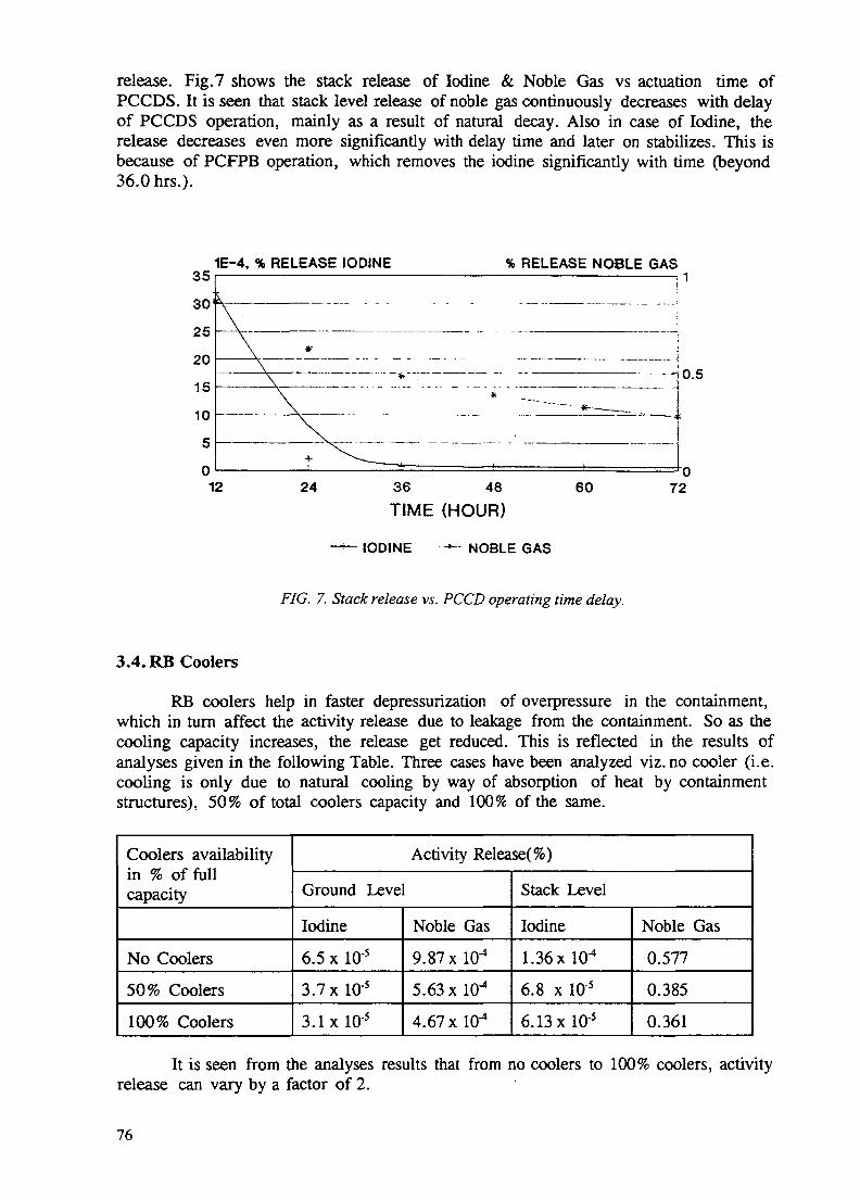
release. Fig.7 shows the stack release of Iodine & Noble Gas vs actuation time ofPCCDS. It is seen that stack level release of noble gas continuously decreases with delayof PCCDS operation, mainly as a result of natural decay. Also in case of Iodine, therelease decreases even more significantly with delay time and later on stabilizes. This isbecause of PCFPB operation, which removes the iodine significantly with time (beyond36.0 hrs.).
1E-4, % RELEASE IODINE % RELEASE NOBLE GASoa
O \J
^«J
20
15
10
5
01
s.
Y ~"" ' " "~ ""'••"•\ -
\\\ *
\+ ^Vfc-^^.
2 24 36 48 60 7
i
0.5
02
TIME (HOUR)
IODINE NOBLE GAS
FIG. 7. Stack release vs. PCCD operating time delay.
3.4. RB Coolers
RB coolers help in faster depressurization of overpressure in the containment,which in turn affect the activity release due to leakage from the containment. So as thecooling capacity increases, the release get reduced. This is reflected in the results ofanalyses given in the following Table. Three cases have been analyzed viz. no cooler (i.e.cooling is only due to natural cooling by way of absorption of heat by containmentstructures), 50% of total coolers capacity and 100% of the same.
Coolers availabilityin % of fullcapacity
No Coolers50% Coolers
100% Coolers
Activity Release(%)
Ground Level
Iodine
6.5 x 10'5
3.7x 10'5
S. lxlO' 5
Noble Gas9.87 x 10-4
5.63 x 1<T*
4.67x10"
Stack Level
Iodine
1.36X10⁻⁴
6.8 x lO'5
6.13x 10⁻⁵
Noble Gas
0.577
0.385
0.361
It is seen from the analyses results that from no coolers to 100% coolers, activityrelease can vary by a factor of 2.
76

5.5% RELEASE (1E-4) RELEASE
0.05
20 40 60TIME DELAY (HOUR)
-0.04
-0.03
-0.02
-0.01
80
IODINE NOBLE GAS
FIG. 8(a). Ground level release vs. PCCD operating time delay.
0.1 _0.01 i
1.000E-03|1.000E-04|1.000E-05 i1.000E-06 f1.000E-07E1.000E-08 k1.000E-09JJ1.000E-10 —
% RELEASE RELEASE
x\
20 40 60TIME DELAY (HOUR)
- 1.1
-0.9
-0.7
-0.5
^0.3
—'0.180
IODINE NOBLE GAS
FIG. 8(b). Stack level release vs. PCCD operating time delay.
4. OPERATOR ACTION & MANAGEMENT STRATEGIES
In the above sections the role and effectiveness of different ESFs have beendiscussed along with results of analyses. Out of four ESFs discussed, operation of RBcoolers and secondary purge system is automatic, but PCCDS & PCFPBS operation ismanual. In case of accident condition, proper operator action can reduce the release ofactivity significantly. The required observation and action on the part of operators, inoperating the ESFs have been described in the following steps.
77

4.1. Observations by Operators
Required observation/action for effective use of ESFs are as follows:
i) Assess the level of activity in the RB atmosphere from signals of activity monitors.
ii) Check the condition of compressed air leakage (i.e. rate of leakage) into thecontainment.
iii) See the status of RB coolers operation i.e. whether there is any partial failure.
iv) Note, whether SC purge system is operating. If in operation, what is the pressurein secondary containment and whether negative pressure is developed in thesecondary containment. Negative pressure should be developed quickly (withinpre-estimated time), if SCRPS operates as per design intent.
v) Monitor, the prevailing weather condition at the site.
4.2. Management Strategies
From the above observation if it is found that activity level is not high, RB coolersand secondary purge system are operating normally, then no immediate manual actionis called for.
However, to reduce the iodine activity concentration PCFPB system can be startedafter some deliberate initial delay. This is to settle down the atmospheric condition inRB and to avoid more iodine loading in filters. Also it may help in large aerosols tosettle down, thus prefilter will not be loaded unnecessarily. A delay of about 5.0 hrs isconsidered in present emergency operating procedure.
Next if continuous compressed air in leakage exists (even after isolating nonessential air lines, as mentioned in 2.5) then, depending upon containment pressurizationrate operator has to decide whether PCCDS operation is called for. If possible thisshould be avoided. But in case it is seen that the secondary purge system is noteffectively functioning and negative pressure is not developed, in that case to avoidexcess ground level release, PCCDS can be operated. Fig.8 (a&b) shows the variationof ground level and stack level releases with respect to delay time of PCCDS operationwhen there is no secondary purge available.
It is seen that early operation of PCCDS is more effective in reducing groundlevel release when SCRPS is not operational. However, stack release decreases withincreasing delay time. This two opposite trend results in a optimum delay time, whereeffective dose will be minimum from combined effect of ground and stack level releases.
Also another important factor which operator has to consider is the prevailingweather condition. It is to be noted that normal practice in safety analyses for dosecalculation is to consider Pasquill's weather condition -F for ground level release andPasquill's weather condition -B for stack level release which are most conservativeassumptions. But in actual situation if ground level releases stop due to negative pressurein secondary annulus, then operator can delay the operation of the PCCDS, depending
78

on favorable weather condition and the direction of wind flow to minimize theconsequence of stack release. By the time operation of PCCDS is called for (typically 24hours or more), a senior level team of experts will be available to guide the emergencyoperation, who can take into account the various factors discussed above, includingoperating status and effectiveness of various ESFs. The operators will be equipped withthe software for carrying out the release calculations (based on the prevailing status ofESFs and weather conditions) in computer. Thus the quantitative estimates will help intaking appropriate management strategies.
NEXT PAGE(S) Ileft BLANK |7Q

ANALYTICAL STUDIES RELATED TO INDIAN XA9846923PHWR CONTAINMENT SYSTEM PERFORMANCE
S.K. HA WARE, S.G. MARKANDEYA, A.K. GHOSH,H.S. KUSHWAHA, V. VENKAT RAJReactor Design and Development Group,Bhabha Atomic Research Centre,Trombay, Mumbai,India
Abstract
Build-up of pressure in a multi-compartment containment after a postulated accident, thegrowth, transportation and removal of aerosols in the containment are complex processes ofvital importance in deciding the source term. The release of hydrogen and its combustionincreases the overpressure.
In order to analyse these complex processes and to enable proper estimation of thesource term, well tested analytical tools are necessary. This paper gives a detailed account ofthe analytical tools developed/adapted forPSA level 2 studies.
1.0 INTRODUCTIONThe Indian Pressurised Heavy Water Reactor (PHWR) is provided with a suppression
pool type of containment designed to withstand the consequences of the loss of coolant accident(LOCA) and the main steam line break accident (MSLBA). In the event of a postulatedaccident, the steam flashes into the containment, leading to pressure build-up. In case of asevere accident, radioactive aerosols may be released into the containment There is also apossibility that due to metal-water reaction, hydrogen may be generated and released into thecontainment.
In order to analyse the performance of the containment system under accidentconditions, a programme of analytical and experimental studies is being pursued at theBhabha Atomic Research Centre. As a part of this programme, the Containment TransientAnalysis code CONTRAN has been developed to analyse the pressure and temperaturetransients in containment, following LOCA and MSLBA. For the analysis of hydrogen mitigationphenomena in the containment using catalytic recombiners, the code HYRECAT has beendeveloped. To analyse the complex processes of transport, growth, deposition and removalof aerosols within the containment the code NAUA/MOD5 has been adapted. For analysing theaerosol scrubbing behaviour of the suppression pool, the code SPARC has been adaptedafter incorporating suitable modifications.
A detailed account of the development, validation and adaption of the analyticaltools for the analysis of the containment response following an accident is presented in thefollowing sections.
2.0 THE CONTAINMENT OF INDIAN PHWRsThe PHWRs of standardised design in India use a double containment (Fig. 1), the
inner (primary) containment being made of prestressed concrete and the outer (secondary)containment being made of reinforced concrete. The annular gap between the two containmentsis maintained under partial vacuum to prevent leakage from within to the atmosphere. Theprimary containment can be further subdivided into two accident based volumes called V1(drywell) and V2 (wetwell). These two volumes are interconnected by the vent system viathe vapour suppression pool. The vapour suppression pool, which passively absorbs energyreleased during LOCA, also helps in the scrubbing of a part of fission products released, if any,in the event of accidents leading to core damage.
81

SUPPRESSION POOLSUPPRESSION POOL CHAMBER
GROUNDLEVEL^
-ACCESS SHAFT
-STRESSING GALLERY
I——I vi
Fig.l: Typical Cross-Section of 220 MWeIndian PHWR Containment Building
3.0 CONTAINMENT SYSTEM PERFORMANCE STUDIESThe source term for the environment depends among other factors, upon the
integrated over-pressure in the containment, the air-borne concentration and characteristics ofthe aerosols released into the containment and the leak tightness performance of thecontainment. The containment overpressure could be due to a LOCA or MSLBA. Release ofhydrogen and its combustion could also result in further pressurisation. Various naturalprocesses such as heat absorption by the containment structure help in reducing thecontainment overpressure and aerosol decay and deposition processes help in reducing theair-borne aerosol concentration in the containment, thereby reducing the source term for theenvironment. In addition, different engineered safety features employed in the plant help inmitigating the consequences of the accident. To analyse these complex processes and to
82

enable proper estimation of the source term, well tested analytical tools are necessary. Thesetools are either specifically developed or suitably adapted for the specific reactor systemand satisfactorily validated. Sensitivity analysis is required to be carried out to quantify theinfluence of various factors on the containment design parameters. Such validated and welltested computer codes could then be used to analyse and improve the performance of thecontainment system.
4.0 ANALYTICAL STUDIES ON CONTAINMENTBEHAVIOUR
4.1 CONTAINMENT THERMAL-HYDRAULIC TRANSIENT ANALYSIS
The CONtainment TRansient ANalysis code CONTRAN has been developed toanalyse the pressure and temperature transients in the containment, following LOCA andMSLBA. The code has been extensively validated against data from in-house and otherexperiments. A large number of analyses have been carried out using the code CONTRAN forIndian PHWRs.
4.1.1 Computer code CONTRAN
The multi-compartment containment geometry is modelled in the code by a network ofvolumes interconnected by junctions. The detailed formulation of the code is described inRef. [1]. Salient features of the code CONTRAN are as follows:
1. Consideration of various heat sinks and heat transfer processes.
2. Vent clearing transient model for vapour suppression pool based on 1-D momentumequation [2].
3. Differential pressure driven hydrogen transportation model.
4. Hydrogen combustion model based on Adiabatic Isochoric Complete Combustion (AICC)of hydrogen.
4.1.1. Validation of the code CONTRAN
The code has been extensively validated using the test data from various sources asdescribed below.
a. One-Tenth Scale Vapour Suppression Pool Containment Experimental (VSPE)Facility, Kalpakkam, India
The experimental facility (Fig. 2) at Kalpakkam, (India) is a one-tenth scale model of thevapour suppression pool type multi-compartment Indian PHWR containment. A large numberof tests with blowdown from a PHT system model were carried out in this test facility to studythe influence of various governing parameters on containment behaviour [3,4,5]. One suchtypical result showing comparison between code predictions and the experimental data inrespect of pressure transients in V1 (drywell) and V2 (wetwell) for the test M4LO [1] isshown in Fig.3. The designated test was performed to simulate a large break LOCA in MAPS(Madras Atomic Power Station) reactor.
It can be seen from Fig. 3 that the first pressure peak of 121 kPa, corresponding topressure buildup in the fueling machine vault till the rupture of blowout panel has beenpredicted correctly. The subsequent pressure transients and the value of the second pressurepeak of 116 kPa (due to pressurisation of V1 until vent clearing) seem to be on the conservativeside with respect to the test data. The comparison of CONTRAN predictions with data fromother tests are also of similar nature and are generally found to be satisfactory.
b. Battelle Frankfurt Containment (BFC) Test Facility, Germany
The Battelle Frankfurt Containment (BFC) test facility in Germany (Fig. 4), is a one-fourth scale model concrete containment with a total free volume of about 580 cu. m. [6J. The
83

C P 3
/ ,CT3
PRESSURE RELIEF CHAMBER
BRACKET TOR BLOW OUT PANEL
REACTION PLATEFUELLING MACHINE VAULT
RUPTURE WSCASSEMBLY
Q DRYWELL
PUT SYS1FM MODEL
* PRESSURE TRANSDUCER
WETWELL O THERMOCOUPLE
Fig. 2: One-Tenth Scale Vapour Suppression PoolContainment Experimental (VSPE) Facility
eri
0)pJ3w7Ja;^-t
OH
KO -
120-
115-
no:
105-
-
100- 10
A - CONTRAN PREDICITONS-F.M. VAULTDnD B - EXPERIMENTAL DATA -F.M. VAt'LTBOP c _ CONTRAN PREDICTIONS-VOLUME V2roptur«iD - EXPERIMENTAL DATA -VOLUME V2
..'"" "•--4.
/ Iv/c
.- ' ' D.^^^* - vents cleared
i i i i i i " i i | i i i r t i i i ( | T i ( i i i i i i * i ' i r i t i f
5 10 15 2(Time, Seconds
Fig. 3: Pressure Transients in V1 and V2 for Test M4LOin One-Tenth Scale Vapour Suppression poolContainment Experimental Facility
84

Flj. 4 ONE-FOURTH SCALE 8ATTEILE FRANKFURTCONTAMMENT HOOEL (BFC)
containment model has several compartments with a provision to select different multi-compartment configurations. Validation of the code CONTRAN has been successfully carried out[7,1] using the data from the two blowdown tests designated as BFC Test-01 and BFC Test-015 [8]. The code validation results for the Test-015 are presented in Fig.5.
The Test-D15 involved blowdown of saturated steam for 2.92 seconds from 69.8 bar inroom R6 (Break Compartment). The results comparing the CONTRAN predicted pressuretransients in the break compartment R6 with the test data up to 2.5 seconds are shown in Fig.5a.The corresponding predictions of COBRA-NC for this test, reported earlier [8], are also shown inFig.5a for comparison. The pressure transients predicted by the code CONTRAN for the othercompartments viz. R8, R7, R4 and R9 are compared in Figs.5b-e, with the experimentaldata and the COBRA-NC code predictions. The CONTRAN predicted pressure transientsare observed to be conservative with respect to the test data.
c. CSNI Numerical benchmark Test
The code CONTRAN has also been successfully validated [9] using the data from thenumerical benchmark test [10] devised by the Committee on the Safety of Nuclear Installations(CSNI) of OECD. The benchmark exercise was devised to test the containment analysiscomputer codes for numerical accuracy and convergence errors in the computation of mass andenergy conservation for the fluid and in the computation of heat conduction in structural walls.
The benchmark test model, shown schematically in Fig.6, consists of a single fluidvolume into which steam and water are injected and from which heat is transferred to a singleconcrete wall. Based on the semi-infinite solid heat slab with a specified constant heat transfercoefficient on the inner wall surface, analytical solutions were provided to arrive at thetransient wall surface temperature, total pressure and steam partial pressure in thecontainment. The code CONTRAN successfully predicted all the three transients with goodagreement. Fig.7 shows the comparison of predicted transients for total containmentpressure (Fig.7a), steam pressure in the containment (Fig.7b) and structural wall surfacetemperature (Fig.7c) with the test data.
4.1.2 Analysis of Indian PHWR Containment using code CONTRAN
Using the code CONTRAN, a large number of analytical case studies have beencarried out to estimate the effect of variation of the following parameters on thecontainment pressure-temperature transients [11].
i. suppression pool bypass areaii. surface area of the containment structureiii. heat transfer to the structural membersiv. multi-compartment configurationv. initial relative humidity in the containmentvi. initial temperature in the containmentvii. loss coefficient of the vent systemviii. integrated mass/energy discharge into the containment
85

zoo-
180-
leo-
100-o.o
A - CMRA-NC6 - CONTRAN PREOtCTKWS
-t -tXPfRWENTAl DATA
o.a i.o 1.5Tint. Sttwrfi
2.0 8.5
Fig. 5a; Pressure Transients in Room R6(.Break Campartment) for BFC Test D-15
ZOO-
180-
180 -
UO-
1ZO-
1000.0
A - COBRA - HC PRC0CT10NS8 - COMTRAH PREOCTICWSC - EXPERIMENTAL DATA
8.0 e.s0.8 1.0 1.9Urn. Sttmh
Fig. 5b: Pressure Transients in Room R8for BFC Test D-15.
zoo
180-
160-
140-
1CO-
100
A- C08RA-NC PREOKTKmS6 - tOHTRAH WEOCTIOKSt - EXWHMEKTAl DATA
O.S 1.0ItH.
Fig. 5c: Pressure Transients in Room R7for BFC Test D-15.
zoo
(80-
180-
1ZO-
1000.0
» - tOBRA-K1 - COKTRAH PREOKTIONSC - EXPEMHENTAL DATA
0.5 t.O 1.5TkM. Stnndi
2.0 2.5
Fig. 5d: Pressure Transients in Room R4for BFC Test D-15.
zoo
180-
180-
*cI uo-
1ZO-
1000.0
A - COBRA-MC PREnCTIONS• - tOHTKAN PICOKTWSC - EXPERtCNTAl. DATA
0.5 1.0 t S 20 8.5Tim.
Fig. 5e: Pressure Transients in Room R9for BFC Test D-15.
86

ConcreteWall(constantthermalproperties)
Single roominitially filledwith air
Specifiedsteam/waterfrow- as -functionof time
Fig. 6: CSNI Numerical Benchmark Test Model
1000
S-f3«•
409-
1009-
9- I I i I , I I , , I i I . , I I ) , I i , i , , , . , ,0 1 2 - 3 4 - 3 8
Time. Second*
Fig. 7a: Total Pressure in Containmentof CSNI Benchmark Test Model
2« 3 4Time. S«cond«
Pig. 7b: Steam Pressure in Containmentof CSNI Benchmark Test Model
423
278
Fig. 7c: Wall Surface Temperature ofContainment of CSNI Benchmark Test Model
87

Results of some of the analyses, e.g. the effect of variation of the suppressionpool bypass area (Fig.8a), surface area of the containment structure (Fig.Sb), heat transfer to thestructure (Fig.Sc) and multi-compartment configuration (Fig.Sd) on the containment peakpressure are presented.
It has been observed that, the containment peak pressure increases withincrease in suppression pool bypass area and decreases with increase in the heat transfercoefficient and surface area of structural heat slabs.
I1.1M
M.IM
1.006
0.066
vttMW V1
(b*M tttmttt to Mraetm*fcy Tifdnl motel)
8uf>p>«Mlon fool
1.100
1.050
1.000
0.090
0.000
i 0.850
Art*,II 0.800
vz<h««t tr«nst«r U ftnctvr*ly Tafuol motol)
Snppr«ni«B Pool >n>»»« Arc*. >q.n.
Fig. 8a: Variation of Containment Peak Pressure with SuppressionPool Bypass Area following MSLBA in 220 MWe Indian PHWR
O.M«
o.«eo
«.aoo
•.760
IO.PM
Co.ooe
io.we
|O.BM
O.TtMi \
,0.706 ^
O.MC ^
V2
Utxurftt to «tn«tity T«*«ml uofet)
of Snrfoo* Arc*
II
Fig. 8b: Variation of Containment Peak Pressure with Surfacearea of Structure following MSLBA in 220 MWe Indian PHWR
* i.iorinrr i1.00
0.06
0.00
9M
0.80
Fig. 8c: Effect of Suppression Pooland Structural Heat Transferon Containment Peak Pressurefollowing MSLBA
• Nombw of Comf>«rlm «n t»
Fig. 8d: Effect of Multi-compartmentgeometry of Containment onPeak Pressure following MSBLA
88

The code CONTRAN, is extensively used for studying the performance of thecontainment of IPHWRs for various LOCA/MSLBA scenarios [11].
4.1.3 Experience gained during validation of the code CONTRAN
Heat and mass transfer processes play an important role in the estimation of thedesign pressure and temperature of the containment of a Nuclear Power Plant. While using aparticular model for the condensation heat transfer processes, the conservativeness of themodel should be ensured. The conduction heat transfer in the structure is better modeled byusing logarithmic grids, with the grid size increasing from inner to outer surface. The use ofuniform grids may result in under-estimation of the containment design pressure. Lowerinitial relative humidity and lower initial temperature in the containment result in higherdesign pressure. Sensitivity analysis helps in assessing the influence of various parameters inarriving at a conservative estimate of the containment design pressure.
4.2 HYDROGEN BEHAVIOUR IN CONTAINMENTSince the accident at Three Mile Island (TMI) Nuclear Power Plant, there has been a
great deal of interest regarding the behaviour of hydrogen in the containment. In the event ofhighly unlikely occurrence of a severe accident in nuclear reactors, a large quantity of hydrogencould be generated. The hydrogen so generated will be confined within the containment. Dueto the very large volume of containment of IPHWRs, the global hydrogen concentration isestimated to be lower than the deflagration limit of hydrogen-air mixture. Depending upon thedistribution characteristics of hydrogen in a multi-compartment containment system, there couldpossibly be a formation of local pockets of high concentration. If the deflagration limit isexceeded, it can cause combustion. This exothermic reaction may cause furtheroverpressurisation of the containment. To mitigate the consequences of such a situation,there are currently four approaches being investigated worldwide, viz.
* inertisation of the hydrogen-air mixture,* deliberate ignition of combustible mixtures,* catalytic recombination of hydrogen with oxygen [12].* combination of deliberate ignition and catalytic recombination [13] or simultaneous
inertisation and catalytic recombination [14]
Among these, the catalytic recombination method offers promising potenua. -... .^its hydrogen removal efficiency even at low hydrogen concentrations and in presence of steam,as has been demonstrated by the reported experimental studies [12].
4.2.1 Computer code HYRECATFor the analysis of hydrogen mitigation phenomena in the containment using catalytic
recombiners, the code HYRECAT has been developed [15,16]. The model is based on thesolution of equations for mass and energy conservation within a homogeneously mixedhydrogen-air-steam mixture undergoing oxidation of hydrogen on the catalyst surface. The salientfeatures of the code HYRECAT are as follows.
4.2.2 Salient Features of code HYRECAT1. The kinetics of catalytic oxidation of hydrogen is described by Arrhenius type empirical rate
equation, (on the basis of unit mass of catalyst or unit area of the catalyst coatedsurface) [17,18].
2. Appropriate heat transfer mechanisms are modelled for the dissipation of the heat ofreaction from the catalyst to the surroundings.
3. The code can analyse the deliberate ignition mode of hydrogen recombination and also thedual mitigation system involving catalytic recombiners and igniters together. The transientcontainment pressure and temperature consequent to the combustion is evaluated byusing(a)AICC and (b) laminar burning velocity models [19] alongwith various thermalhydraulic processes.
4.2.3 Validation of code HYRECATBhabha Atomic Research Centre (BARC) has successfully developed a special type
of activated platinum catalyst and the laboratory tests have demonstrated its satisfactory
89

performance. Further tests on this catalyst system are planned on an engineering scaletest facility (see Fig.9). The validation of the code HYRECAT has been carried out [15] usingdata from two of the several laboratory tests performed at BARC. The test was performed in a22 litre stainless steel vessel with a catalyst coated substrate of known dimensions and knowncatalyst loading (i.e. mass of catalyst per unit area), with initial hydrogen concentration of 5.1% (v/v). The variation of the total pressure in the vessel was recorded continuously.
Excellent agreement has been observed between the predictions of HYRECAT and themeasured total pressure in the vessel as seen from Fig.10. More detailed results of validationare presented elsewhere [15].
4.2.4 Analysis of planned experiments using code HYRECATLarge scale experiments are planned on a 22 cu.m. vessel to examine the behaviour of
the catalytic recombination system on engineering scale (see Fig.9) and to test the performanceof the device [20]. The test facility consists of hydrogen injection and monitoring system,catalytic recombiner device, steam and air injection provisions, various instrumentations andthe safety devices installed on the model containment vessel. The code HYRECAT was usedto analyse these tests to be conducted at BARC and predict (pre-test) the performance ofthe catalytic recombiner system. The predicted behaviour for a typical test, in terms of thecontainment pressure, temperature, hydrogen concentration, relative humidity and reactionrate etc. are presented in Figs. 11 a-f. These tests would generate a data bank useful for furthervalidation of the code.
4.3 AEROSOL SOURCE TERM ANALYSISTo enable a realistic assessment of the source term, the complex processes of
transport, growth, deposition and removal of aerosols within the containment are required to beanalysed. The codes NAUA/MOD5 [21] and SPARC [22] have been adapted for this purpose.
HYRECAT PREDICTIONS FOR EXPT. ON CATALYTICRECOMBINATION OF HYDROGEN (22 litre vested
114.00-
* * * EXPERIMENTALCALCULATED
2000 2SOO
Fig. 10: Comparison of HYRECATPredictions with experimentaldata on Laboratory Scale Test.
Fig. 9: Experimental Setup for HydrogenMitigation Studies using catalyticRecombination
90

M* f«U t*W Hit Mb*Tim*.
a. pressure transients
ZZ.SJL•••O ClftVC
m MS*'&*""&» twoTim«. 8*cond«
b. temperature transients
jj0""ij5i"'Ytij tooe ' *j »Time. Second*
c. variation of hydrogenconcentration.
Tim*. Second*tiw §*»"""i»W" iflio "*&• tip*
•time. S*cofid*
d. variation of R. H. e. variation of HiO mass f. variation of reaction rate
Fig. 11: Analytical results for the proposed experiment for hydrogen mitigationstudies using catalytic recombination on model containment.
4.3.1 Computer code NAUA MOD 5NAUA is an advanced multi-compartment aerosol behaviour analysis code for use in
reactor containments following core-melt accidents. It models the physical aerosol phenomenaoccurring naturally in the containment. It models gravitational deposition, diffusional plate-outand diffusio-phoresis as removal mechanisms. Among the interaction processes, the codeconsiders Brownian coagulation, gravitational agglomeration and aerosol growth by steamcondensation. The code is not integrated with the containment thermal hydraulics. NAUA cantake into account the build-up of upto 50 nuclide species on a size-dependent basis.
4.3.2 Assessment of code NAUA MOD 5 with the Falcon Aerosol TestThe Committee on the Safety of Nuclear Installations (CSNI) of OECD organised
during 1992-94, the International Standard Problem Exercise no. 34 (ISP-34) on aerosolbehaviour in the primary circuit and the containment of a nuclear reactor. The exerciseinvolved carrying out specific experiments in the Falcon Test Facility at Winfrith TechnologyCentre, U.K. and analysis of these experiments using different computer codes [23].
The tests were performed in the small scale Falcon test facility shown schematically inFig.12. The facility comprised of core region, primary circuit piping and the containment. Simulantfuel samples clad in zircaloy-4 were placed in a silica vessel simulating the core region Heatingof the fuel was achieved in a 40 kW induction furnace. Helium gas as a carrier medium wasadmitted at the bottom of the silica vessel and aqueous boric acid solution could beintroduced on the heated sample. The thermal gradient tube and the stainless steel pipesimulated the primary circuit. The containment was a 0.3 cu.m stainless steel chamberconnected to the primary circuit.
Containment analysis of these tests was carried out at BARC using the computer codeNAUA MODS. The code calculations for one of the experiments, viz. FAL-ISP-1 are presentedand compared with the experimental data in Figs. 13a-d [24,25]. Many of the code predictionswere found to be in reasonably good agreement with the experimental results. The containmentfloor deposits are predicted closely, whereas the wall deposits are underpredicted. However, the
91

OmMi »nf^ilflllM M / fctKttr ^ pjS,
Mnlca Sml Ttemtf / Ik /U—i*T Pramt G—tc Afcul.*ObnBot OndkiM TW»/A>mr/ M"" /(04-W«rr) niw
Fig 12 • Falcon test facility for Aerosol Studies
1MB
It-M •
r
v^
J it-e*
——— CAOMTUW fCMraMBdl
« CADMIUM (brrriimo
I ' • • • I I • ' ' i I
too ige too"Pins, fnhi
Fig. 13a: Boron and Cadmium airbornemass concentrations in containment
•CALCULATED
EXPSBIM6WTAL
I • • • • I
too 180 too no 900Time, mln
Fig 135- Cesium airborne massconcentration in containment
II
It-01
1J-OT
mi - •
I • • • • I t • < • • I i100 1BO tOO t00 900 390
Fig. 13c: Cumulative deposition of Ctsium
i.e-ei -
1M.
1E-OS -
IE-04 -
IE-OS -
1E-OI -
1E-OI -
I
j
1
1
1
S^ ,,__---
/f
1t
' — — CUM LEAKAGE
———— AmOOONCUAM
CUM.SGD1MEWTATION
- - CUM CXH-U3KJN
f
i 1 • 1 • i 1 1 1 ..* > 1 1 1 i 1 1 .1 .-i_l-l 1 . . , , |-i.,A_L...
100 190 SOO 190 100 990Thne mtn
Fig 13d; Removal of aerosols byvarious mechanisms.
92

predictions are observed to be well within the reported uncertainties in the experimentalmeasurements. Augmentation of the code for integral thermal hydraulics and assessment ofthe containment behaviour of Indian PHWRs is in progress.
4.3.3 The computer code SPARCEngineered Safety Features (ESFs) such as suppression pool are a part of the IPHWR
containment system. Besides its intended function of reducing the containment pressure, thesuppression pool also helps in the removal of aerosols.
In order to analyse the aerosol scrubbing behaviour of the suppression pool, the codeSPARC has been adapted after incorporating suitable modifications. The code modelsthe particle capture by condensation of steam, impaction, sedimentation, centrifugaldeposition and diffusional deposition. Growth of soluble particles by water vapour absorption isalso modelled. The removal of aerosols is quantified by decontamination factors (DF)defined as the ratio of concentration of aerosols in the gas entering the pool to that leavingthe pool [22].
4.3.4 Validation of the code SPARCLaboratory scale experiments were carried using a prototype bubbler unit (Fig. 14). The
nebuliser generates wet aerosols from aerosol solution. Compressed air is used for dryingthese aerosols and carry them to the pool of water. Suction produced by the pump forces theaerosol-laden air to bubble through the pool of water. Aerosols were collected on filters afterpassing them through the pool and compared with the case without passing through thepool to obtain the decontamination factors. Experiments with two different sized particles viz.Fluorescein (MMAD = 0.8 microns) and Silica (MMAD = 0.2 microns) were carried out. Figs.15a-bshow the analytically computed DFs as a function of size classes for Fluorescein and Silicaaerosols respectively. The code predictions and experimental results presented in these figuresare found to be in close agreement [26].
— WETWEU.VESSEL (GLASS)
•—COMPRESSEDMR
PUMP WITH FLOWMEASUREMENT SUPPRESSION
POOL
Fig. 14: Suppression pool Aerosol ScrubbingTest FacKrty (schematic)
93
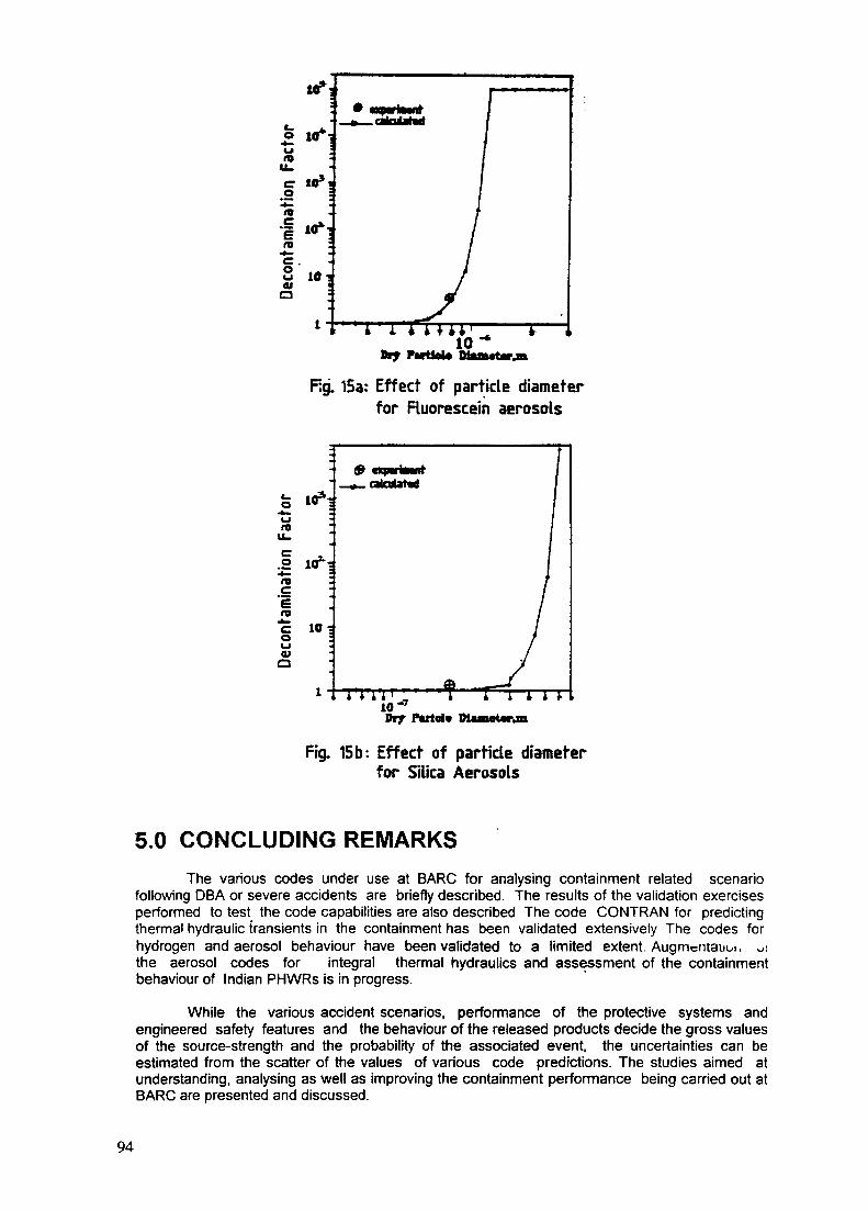
10s
fm
a
i 1 ** '10Biy Partial*
Rg. 15a: Effect of particle diameterfor Ruorescein aerosols
ouro
core
re
<ua.
if;
19'-
.ofeuUM
J * _10 -7Dry Ptrtol*
Fig. 15 b: Effect of particle diameterfor Silica Aerosols
5.0 CONCLUDING REMARKSThe various codes under use at BARC for analysing containment related scenario
following DBA or severe accidents are briefly described. The results of the validation exercisesperformed to test the code capabilities are also described The code CONTRAN for predictingthermal hydraulic transients in the containment has been validated extensively The codes forhydrogen and aerosol behaviour have been validated to a limited extent. Augmcntauui, uithe aerosol codes for integral thermal hydraulics and assessment of the containmentbehaviour of Indian PHWRs is in progress.
While the various accident scenarios, performance of the protective systems andengineered safety features and the behaviour of the released products decide the gross valuesof the source-strength and the probability of the associated event, the uncertainties can beestimated from the scatter of the values of various code predictions. The studies aimed atunderstanding, analysing as well as improving the containment performance being carried out atBARC are presented and discussed.
94
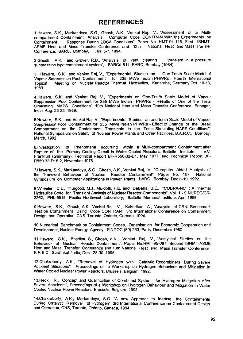
REFERENCES1.Haware, S.K., Markandeya, S.G., Ghosh, A.K., Venkat Raj, V., "Assessment of a Multi-compartment Containment Analysis Computer Code CONTRAN With the Experiments onContainment Response During LOCA Conditions", Paper No. HMT-94-118, First ISHMT-ASME Heat and Mass Transfer Conference and 12th National Heat and Mass TransferConference, BARC, Bombay, Jan. 5-7, 1994.
2.Ghosh, A.K. and Grover, R.B., "Analysis of vent clearing transient in a pressuresuppression type containment system", BARC/l-814, BARC, Bombay (1984).
3. Haware, S.K. and Venkat Raj, V., "Experimental Studies on One-Tenth Scale Model ofVapour Suppression Pool Containment for 235 MWe Indian PHWRs", Fourth InternationalTopical Meeting on Nuclear Reactor Thermal Hydraulics, Karlsruhe, Germany.Oct. 10-13,1989.
4.Haware, S.K. and Venkat Raj, V., "Experiments on One-Tenth Scale Model of VapourSuppression Pool Containment for 235 MWe Indian PHWRs - Results of One of the TestsSimulating MAPS Conditions", 10th National Heat and Mass Transfer Conference, Srinagar,India, Aug. 23-25, 1989.
5.Haware, S.K. and Venkat Raj, V., "Experimental Studies on one-tenth Scale Model of VapourSuppression Pool Containment for 235 MWe Indian PHWRs - Effect of Change of the BreakCompartment on the Containment Transients in the Tests Simulating NAPS Conditions",National Symposium on Safety of Nuclear Power Plants and Other Facilities, B.A.R.C., Bombay,March, 1992.
e.lnvestigation of Phenomena occurring within a Multi-compartment Containment afterRupture of the Primary Cooling Circuit in Water-Cooled Reactors, Battelle Institute e.V.Frankfurt (Germany), Technical Report BF-R550-32-D1, May 1977, and Technical Report BF-R550-32-D15-2, November 1978.
7.Haware, S.K., Markandeya, S.G., Ghosh, A.K., Venkat Raj, V., "Computer Aided Analysis ofthe Transient Behaviour of Nuclear Reactor Containment", Paper No. 107, NationalSymposium on Computer Applications in Power Plants, BARC, Bombay, Dec.8-10, 1992.
S.Wheeler, C.L., Thurgood, M.J., Guidotti, T.E. and DeBellis, D.E., "COBRA-NC : A ThermalHydraulics Code for Transient Analysis of Nuclear Reactor Components", Vol. 1 - 9 NUREG/CR-3262, PNL-5515, Pacific Northwest Laboratory, Battelle Memorial Institute, April 1986.
9.Haware, S.K., Ghosh, A.K., Venkat Raj, V., Kakodkar, A., "Analysis of CSNI BenchmarkTest on Containment Using Code CONTRAN", 3rd International Conference on ContainmentDesign and Operation, CNS, Toronto, Ontario, Canada, 1994.
10.Numerical Benchmark on Containment Codes, Organisation for Economic Cooperation andDevelopment, Nuclear Energy Agency, SINDOC (80)263, Paris, December 1980.
11.Haware, S.K., Bhartiya, S., Ghosh, A.K., Venkat Raj, V., "Analytical Studies on theBehaviour of Nuclear Reactor Containment", Paper No.HMT-95-097, Second ISHMT-ASMEHeat and Mass Transfer Conference and 13th National Heat and Mass Transfer ConferenceK.R.E.C., Surathkal, India, Dec. 28-30, 1995.
12.Chakraborty, A.K., "Removal of Hydrogen with Catalytic Recombiners During SevereAccident Situations", Proceedings of a Workshop on Hydrogen Behaviour and Mitigation inWater Cooled Nuclear Power Reactors, Brussels, Belgium, 1992.
13.Heck, R., "Concept and Qualification of Combined System for Hydrogen Mitigation AfterSevere Accidents", Proceedings of a Workshop on Hydrogen Behaviour and Mitigation in WaterCooled Nuclear Power Reactors, Brussels, Belgium, 1992.
14.Chakraborty, A.K., Markandeya, S.G., "A new Approach to Inertise the ContainmentsDuring Catalytic Removal of Hydrogen", 3rd International Conference on Containment Designand Operation, CNS, Toronto, Ontario, Canada, 1994.
95

15Haware, S.K, Bhartiya, S., Ghosh, AK., Venkat Raj, V/'Studies on CatalyticRecombination of Hydrogen in Indian PHWR Containment", Paper No HMT-95-097, SecondISHMT-ASME Heat and Mass Transfer Conference and 13th National Heat and Mass TransferConference, K R.E C., Surathkal, India, Dec 28-30,1995,
16Haware, S K.. Bhartiya, S., Ghosh, A K , Venkat Raj, V, "Analytical Studies on the CatalyticOxidation of Hydrogen Using the Code HYRECAT", CHEMCON-95, Kalpakkam, India
17 Mayo, JA and Smith, J M., "Catalytic Oxidation of Hydrogen-lntrapellet Heat and MassTransfer", A I Ch E. Journal, Vol.12, No 5, Sept 1966, pp 845-854
18 Markandeya, SG., Chakraborty, AK, "Modeling of catalytic Recombmers for Removal ofHydrogen Dunng Severe Accidents", SMiRT-12/K, Aug 1993, pp 73-78
19Liu, D D.S., McFarlane, R., Laminar Burning Velocities of Hydrogen-Air and Hydrogen-Air-Steam Flames, Combustion and Flame, Vol 49, 1983, pp 59-71
20 Jain, V.K et.al., "Project Proposal For Development and experiments on HydrogenMitigation System", Internal Report, RED, BARC, 1991
21 Bunz, H etal, "NAUA-MOD5 and NAUA-MOD5M - Two Computer Programs forCalculating the Behaviour of Aerosols in a LWR Containment Following a Core-Melt Accident",KfK-4278
22 Owczarski P.C., Schreck R I, Postma A K ;Technical Bases and Users Manual for theprototype of a Suppression Pool Aerosol Removal Code (SPARC) NUREG/CR-3317
23Williams, DA, OECD International Standard Problem Number 34, FALCON CodeComparison Report, AEA RS 3394, Dec 1994
24 Haware, S.K , Ghosh, A K , Sharma, V K , Venkat Raj, V, "Analysis of FALCON Test FAL-ISP-1 Using Code NAUA", Fifth IASTA Conference on Aerosol Science and Technology,BARC, Bombay, Jan 10-12,1994
25 Haware, S K., Ghosh, A.K., Sharma, VK., Venkat Raj, V , Assessment of the ComputerCode NAUA MOD 5 against a small-scale Containment Aerosol Test, J Aerosol Sci, vol 28 (tobe published)
26 Venu Vinod, A , Haware, S.K., Ghosh, A K., Venkat Raj, V , Sapra, B K., Mayya, Y S ,Raghunath, B.R , Sawant, V D., Nair, P V N and Nambi, K S V , Experimental Studies on PoolScrubbing of Aerosols, Sixth IASTA Conference on Aerosol Science and Technology,Ahmedabad, November, 28-30, 1995
96
XA9846924APPROACH TO DEVELOPMENT AND USE OF PSA LEVEL 2ANALYSIS FOR THE CERNAVODA NUCLEAR POWER PLANT
I. TURCU, R. DEACONU, G. RADUInstitute for Nuclear Research,Pitesti, Romania
Abstract
This paper first describes the status of PSA activities for the Cemavoda NPP and the extensionof the PSA work to include Level 2 PSA. Important characteristics of this reactor type for Level 2PSA are outlined. Due to the specific layout of the CANDU reactor the evolution of severe accidentsis considerably different to vessel type LWRs. Accidents can be roughly categorized into threecategories, "severe accidents" which lead to the loss of core structural integrity, delayed loss of corestructural integrity as a consequence of the loss of heat sinks, and fuel channel failures. The currentwork for modelling accident progression in the core region is described. The elements for the Level2 PSA including definition of PDSs, probabilistic containment logic and source term calculation areoutlined. It is pointed out that uncertainties have to be considered which are contained in the modelsto bridge knowledge gaps. For this purpose sensitivity studies will be carried out for key modellingassumptions.
1. INTRODUCTION
The commissioning phase of Cernavoda Unit 1 has been completed and the connectionto the grid for commercial operation has been performed at the beginning of December 1996.During this year it was also decided to restart the unit 2 construction with a tentative schedulefor completion in 2000.
PSA activity for Cernavoda Nuclear Power Plant was initiated in 1988 based on therecommendation and significant assistance of IAEA. Now, a full scope level 1 is completed andreviewed by an IAEA IPERS mission. The implementation of review mission recommendationsas well as the updating of the study to the as-built documentation for Unit 1 are scheduled forJune 1997. During the past 2 years some activities related to PSA level 2 analysis have beeninitiated.
Since 1990, the safety authority (CNCAN) adopted a specific approach on using PSAmethods for the Cernavoda NPP Unit 1 as a licensing documentation. The approach had the goalto enhance the role of the probabilistic methods in the safety documentation in a more detailedmanner in order to be more effectively used during the Cernavoda NPP Unit 1 licensing process.
A PSA level 1 study is at present a prerequisite for Cemavoda NPP Unit 1 license renewalafter the initial 18 months of operation. In the same time, this study is used as a supportdocumentation in the review and assessment activities for Reliability Analysis (RA) and SafetyDesign Matrices (SDM) to be issued for licensing the Cernavoda NPP Unit 1.
Detailed licensing requirements for the Cemavoda unit 2 are now under consideration andthese include the PSA level 1 and 2 analysis.
97

2. STATUS OF PSA ACTIVITIES
In 1988 a limited scope Level 1 PSA (Cernavoda Probabilistic Safety Evaluation, CPSE- Phase A) was started and carried out by the Institute for Nuclear Research (INR) in Pitesti withthe participation of the designer group represented by CITON. The study, contains 9 event treesand fault trees for 17 systems.
Phase A was completed in 1990 and reviewed by an IAEA International Peer ReviewService (IPERS) mission, undertaken within the ROM/91003 project as part of the IAEARegular Program of Technical Cooperation. The IPERS review has identified a number of issuesto be considered in the next phase of the CPSE Study and provided valuable conclusions anddetailed recommendations to be followed and implemented.
The CPSE Study restarted in 1993 as a full scope Level 1 PSA, known as CPSE - PhaseB. Coordinated by RENEL, Safety and Licensing Compliance and performed by an enlargedPSA team, including CITON Bucharest -Magurele and INR - Pitesti, this new phase of the studybenefitted by IAEA assistance under ROM/9/008 Technical Cooperation Project.
Completed in 1995 this phase of the CPSE has been reviewed by an IAEA IPERS missionand the implementation of the review missions recommendations as well as the updating of thestudy to the as-built documentation for Unit 1 are scheduled for June 1997.
Activities related to PSA level 2 analysis have been initiated in 1994 at the Institute ofNuclear Research in Pitesti and CITON Bucharest (Renel Center for Nuclear Engineering andTechnology).
The first step was the familiarization with the Source Term Code Package (STCP),provided by the IAEA, the implementation of the code on PC computers and running somereference test cases.
Furthermore, development of preliminary models, specific for CANDU, and theirimplementation in MARCH3 has been performed. These models includes the residual heattransfer and cooling degradation of fuel channels, fuel channel debris thermal behavior,moderator thermal hydraulics, and the effect of melted debris on calandria vessel wall.
Based on these models we performed some calculations of different accident scenarios.In reference /3/ the results of a loss of service water initiated accident are presented. Theinitiated event has as consequences loss of the shutdown cooling system (SDCS), loss of coolingto the moderator, loss of cooling to the calandria vault water, and loss of ECCS heat exchangers.Simultaneously loss of service water, loss of class IV power and loss of steam generator heat sinkare assumed.
During 1996, the fault trees for containment systems (containment isolation system,dousing system, reactor building air coolers and ventilation system ) have been developed.
Beginning with the next year, a systematic research activity related to hydrogen behaviorin containment is initiated. For 1997 a state of the art investigation is planned (hydrogengeneration, transport and combustion) as well as a preliminary model development for hydrogengeneration.
PSA level 2 activity is benefiting by a significant IAEA support. The fellowships carriedout at Korea Atomic Energy Research Institute provided a good level of competence necessaryfor the initiation of this project. These were particularly useful for providing the technicalbackground necessary for performing the main tasks of the project and the familiarization with
98

the computer code MAAP4 used for CANDU, as well as a specific training related to plantmodels and methods for physical processes, definition of plant damage states, containment eventtrees development and source term analysis familiarization.
For the next 3 years it is planned to perform a complete level 2 analysis for the CernavodaNPP in order to be used in licensing process of the plant and to provide a technical basis for theevaluation and improvements of containment performance.
3. CANDU 600 SPECIFIC FEATURES
The Candu reactors are heavy water-moderated, natural uranium-fueled, and pressurizedheavy water-cooled.
Reactor and Primary Heat System
The Calandria is a horizontal cylinder. It is spanned by the fuel channels and contains themoderator. Each fuel channel consists of a pressure tube surrounded by a calandria tube withCO2 gap in between. Heavy water is used as the coolant and flows at high pressure through thepressure tubes. The moderator is isolated from the hot pressure tube by means of the calandriatube and as a result can be kept relatively cool and can act as a heat sink under certain accidentconditions. The fuel element contains natural UO2 pellets in a Zircaloy-4 sheath.
In case of simultaneous pressure tube/calandria tube rupture, the calandria has beenprovided with rupture discs to adequate discharge the heavy water flow into the containment.
At each end of the calandria there is an end shield, which contains carbon steel balls anddemineralized water in order to provide biological shield and cooling. The calandria assemblyis supported by the calandria vault which is filled with light water. This water can act as apassive heat sink. In case of an accident that leads to the corium collection in the calandriabottom, the vault water provides the ex-calandria cooling. The end shields and calandria vaultcooling is provided by means of a system. If moderator cooling fails then this cooling system candelay melt relocation into the calandria vault.
The primary heat transport system (PHTS) consists of two closed loops and as aconsequence in the event of a loss of coolant accident the rate of the reactor coolant blowdownis reduced. After LOCA the loops are isolated and the intact loop inventory can be maintained.
Special Safety Systems
Emergency Core Cooling System (ECCS)
The basic function of the ECCS is to provide an alternate means of core cooling in case of anaccident which depletes the normal coolant inventory in the primary heat transport system to anextent that fuel cooling is not assured. After LOCA, on PHTS low pressure signal (so-calledinitiating signal) the loops are isolated and if one of the three conditioning signals occurs: highcontainment pressure or high moderator level or sustained PHTS low pressure, ECCS isautomatically initiated by the LOCA signal. The same LOCA signal opens with a delay the mainsteam safety valves to provide the steam generators crash cooldown.
ECCS consists of three stages according to the operating pressure: High, Medium and LowPressure Injection.
99
Shutdown System (SDS)
CANDU reactors are provided with two independent shutdown systems. SDS#1 providesshutdown of the reactor by releasing 28 gravity shutoff rods into the core. SDS#2 can do thesame thing by the rapid injection of a gadolinium solution into the bulk moderator. Both systemsare designed to have no effect in tripping the reactor in case of failure of any support system.
If failure of both SDS#1 and SDS#2 is postulated when they are needed during a transient, thesequence would be very severe due to the CANDU characteristic of positive coolant andmoderator temperature coefficient. However, the failure probability of SDS is very low due tothe CANDU design features.
Containment Dousing System
The dousing system function is to limit the magnitude and duration of containment over-pressure caused by a LOCA or a MSLB (main steam large break) inside the containment. Thesystem consists of the dousing tank (DT) located below the dome of the reactor building and sixindependent spray units connected to the DT.
Reactor Building Air Coolers
One of the main functions of the reactor building cooling system is to provide a long term heatsink (dousing system is the short term heat sink) following a LOCA or a MSLB reducingcontainment pressure and temperature.
Containment Envelope
The containment envelope is designed to restrict the release of radioactivity to the environmentwithin the maximum permissible dose limits in the event of a radioactivity release. Thecontainment envelope consists of: the reactor building; the airlocks; the containment isolationsystem.
Feed-water and Steam Systems
Each primary loop is provided with two steam generators. Each steam line is equipped with anatmospheric steam discharge valve (ASDV) in order to release steam when the turbine condenseris unavailable. Sixteen main safety valves (MSSVs) are provided to protect steam generators fromover-pressure. The condenser steam discharge valves (CSDVS) discharge the main steam directlyto the condenser avoiding the actuation of the MSSVs under severe transients.
Feedwater system supplies water from the deaerator to the boiler level control system viathe main feedwater pump lines or the auxiliary pump line in order to maintain the four boilerat required level during various modes of operation.
4. PLANT MODELS AND METHODS FOR PHYSICAL PROCESSES
The first step in Level 2 PSA is to perform plant familiarization and to determine thoseplant features most likely to impact the progression of the severe accidents. It is necessary toreview plant design information, existing CANDU PSA data and severe accident data.
The following most significant areas of the plant will be reviewed:
engineered safety features which include shutdown cooling system, emergency core coolingsystem, dousing system, reactor building air coolers;
100
interior design of the containment: interconnecting pathways between differentcontainment compartments and the location of equipment will be reviewed to determinemajor heat sinks, to assess circulation flows within containment and to aid the assessmentof hydrogen burning;
containment pressure boundaries will be reviewed to assess containment failure locationsand modes.
calandria and calandria vault design including pressure relief path from calandria and/orcalandria vault and moderator/shield cooling system design.
service building design will be reviewed to assess the potential for radionuclideattenuation following an interfacing LOCA or a containment leak/break into the servicebuilding if the attenuation is possible.
emergency operating procedures.
All those features which are identified to be able to circumvent potential severe accidentuncertainty should be clearly described.
CANDU operation data, severe accident experimental data for CANDU and results fromspecific computer codes analyses will be reviewed to get insight.
As Candu has its own specific structure the terminology used in the Level 2 PSA study isdifferent from that for PWR:
Severe Accident: loss of core structural integrity, and severe core melt occurrence.Example: LOCA followed by the ECCS and moderator unavailability.
Loss of Core Structural Integrity: loss of heat sinks leading to core melt involving fuelchannels failures.
Fuel Channel Failure: simultaneous failure of the pressure tube and calandria tube.
Containment Envelope: comprises the reactor building, sealed penetrations, closed andopen penetrations.
To analyze the accident progression means to track the progression of the accident fromthe onset of core melt until it is assured that no additional release of radionuclides from thecontainment will occur. In order to achieve this task a plant model is necessary to be developedto simulate the response of the CANDU plant from accident initiation to the source term models.The code MAAP-WS developed for the Wolsong NPP includes models for thermal hydraulics,fission products behavior in the PHTS, calandria, calandria vault and containment during severeaccidents.
Another important task is to prepare the plant data which is necessary to run the code.The data can be categorized into generic data which is invariant among the sequences andsequence dependent data which are in concordance with the scenario. Generic data includesplant geometrical data, initial conditions, operational setpoints, engineering safeguardcharacteristics, fission products initial inventories, etc. Sequence dependent data includessequence specific information such as: break size and location, what and when operator actionare taken, etc. To prepare these data, the accident sequence should be identified in plantdamage- event trees and containment event trees in advance.
101

If the above tasks are done, analysis of the physical progression of an accident usingdeterministic models is performed to support the following activities:
Level 1 success criteria evaluationevent timing determinationsensitivity studies to support GET development and quantificationinput preparation to source term analysis.
5. PLANT DAMAGE STATES
The interface between the Level 1 system analysis and the Level 2 containment analysisis the classification of each accident sequence into plant damage states (PDS). The purpose ofthis classification is to reduce the number of the accident analyses required while retaining theessential spectrum of probable accident progression. To group the large number of core-meltsequences into a set of states or bins it is necessary to define a set of functional characteristicsof system operation that are important to the accident progression, containment failure andsource term analyses.
Level 1 event trees will be extended to include the status of the containment safeguards.The quantified results of extended Level 1 event trees will be propagated through frequenciesof the PDSs.
Plant Damage State Grouping Parameters
PDSs are the entry points of the CETs. The following parameters are important for thePDS characteristics: accident progression in the containment; time, mode and location of thecontainment failure and the radionuclides source terms. The following parameters are proposedto be selected:
Containment Bypass which divides the Level 1 sequences into by-pass and non-bypassgroups.Containment Isolation Status which segregates the Level 1 sequences into distinct groupsbased on the status of the containment building isolation at the time of core melt.Transient or LOCA which makes distinction between transient and LOG A sequences.Dousing Spray which determines whether the dousing spray operates.Shield Cooling which determines whether this system operates.Local Air Coolers which determines whether this system operates.
Plant Damage State Definition
Plant damage states are defined by combinations of the possible values for each of thePDS parameters. These combinations are reviewed to delete combinations which are considerednot to be physically possible or are counter to other definitions used in the analysis.
The PDS logic diagram is a useful tool for combining the various grouping parameters intounique PDSS. This diagram is constructed with PDS grouping parameters as decision branchesto aid in the assembly of specific plant damage state characteristics from the matrix of allpossible combinations allowed by the PDS grouping parameters.
6. CONTAINMENT EVENT TREES
Containment event trees (GET) are used to model the containment response by depictingthe various phenomenological processes, containment conditions and containment failure modesthat could occur during severe accidents.
102

The integrity of the containment is one of the most important issues in evaluatingradioactive releases. Knowledge of performance of the containment structure to internal pressureand temperature transients associated with the accident is essential in determining probabilitiesof failure and estimating consequences of such failure. The PS A approach determines the medianinternal pressure capacity at which failure of the containment will occur and the associatedvariability from which the conditional probability of failure for a given level of internal pressurecan be estimated. Failure of the containment is defined as incipient leakage and release ofradioactivity material into the atmosphere.
CANDU Coatainment Design Features
The reactor building is designed in accordance with AECL Design Guides. The containmentstructure is a prestressed concrete building consisting of three structural components: abase slab,a cylindrical wall and a spherical segmental dome.
To assist in leakage control and cleaning, the containment structure has an internal liningcomprising of a plastic coating applied to the inner surfaces of the concrete outer dome andwalls.
Beneath the outer dome there is a second dome having an opening in the crown, whichtogether with the perimeter wall forms a container to provide storage of water for dousing andemergency core cooling.
Systems closed within containment, which pass through the containment boundary, andwhich are open to the atmosphere outside containment, are part of the containment envelope.Similarly a system closed outside containment, and open to the atmosphere inside containment,is part of the containment envelope.
The containment structure is designed to withstand an internal pressure of 0.125MPa.
Method of containment ultimate capacity evaluation
The Probabilistic safety assessment approach for the containment overpressure evaluation isbased on a simplified fragility model. The tasks of a containment internal pressure fragilityevaluation consist of:
- Identification of potential failure modes
- Development of containment fragilities
- Estimation of leak areas.
Containment event tree
CETs provide a quantitative logic model for examining the spectrum of severe accidentprogressions and they provide the framework for evaluating the deterministic outcomes of specificaccident progression.
The event tree technique is used in modelling containment response. The GET should beconstructed in sufficient detail to address the occurrence of various phenomenological events,processes, and human interaction that have been determined to be important to containmentfailure and source term evaluation. In order to be more scrutable, a GET with a reduced numberof events should prove adequate. Complex phenomena can be treated in detail in theDecomposition Event Tree (DET) (or in the phenomenological fault trees).
103

Each PDS end point represents a unique accident progression starting point with respectto the GET.
It follows that a GET must be developed and quantified for each PDS. In practice, therewill be many commonalties for most accident sequences, except for the containment bypasssequence and containment isolation failure.
The events in the GET should contain only those phenomena expected to have thegreatest impact on the containment accident progression. Events that contribute to these eventsand/or which aid in the assessment of the event branch probabilities should be relegated toDETs (or fault trees). Each top event has its own DET (or fault tree). DET consist of theimportant subevents that contribute to the top event and is used to quantify the branchprobability of the top event.
7. SOURCE TERM ANALYSIS
A source term is the amount of radioactivity material which is released to theenvironment, along with information on the timing, energy, duration, and location of releasepoint.
The CETs produce a large number of end states, some of which are either identical orsimilar, in terms of key release attributes. The analyses of all accident sequences of interest areprohibitively expensive and time-consuming. As a result the sequences are categorized by theirradiological characteristics and potential off-site consequences in what we usually call 'releasecategories/bins'.
A set of release categories is then defined such that all accidents assigned to the samecategory are assumed to have the same release fractions of fission products. These release groupsare defined on the bases of appropriate attributes that impact fission product releases. Attentionshould be paid to the requirements of dose calculation as the interface between analysis and dosecalculation. To set up the release categories, binning parameters are selected. These parameterswill be used as the headings of the source term category diagram. In order to finalize the list ofthe parameters, previous CANDU and PWR PSA reports will be reviewed and additionalplant-specific studies must be performed.
The radiological source terms divide the radioactive material into several source termgroups whose elements have similar chemical, physical and physiological properties. In the PWRstudy the 60 isotopes are placed in nine radionuclides classes which are treated individually inthe source term analysis: Inert Gases, Iodine, Cesium, Tellurium, Strontium, Ruthenium,Lanthanum, Cerium, Barium. In case of CANDU reactors, tritium must be considered differentlyfrom PWR, as it is produced outside the fuel and is present in the primary heat transport coolantand in the moderator coolant during normal operation.
The objective of the source term analysis is to provide a radiological source term for eachrelease category. In order to estimate the source term, the following steps are usually performed:
1. the GET end-points grouping, which would lead to similar potential radionuclide releasesinto release categories;
2. determination of the in-core fission products inventory at the initiating time of theaccident;
3. determination of the physical progression of the representative accident sequences foreach release category;
104

4 determination of the rate of radionuclides released from the j^^attenuation behavior in plant systems and ultimate rate of release from the plant.
and
in Level 2 PSA studies, considerable uncertainties in source terms exist and care should
assumptions and parameters should be made.
REFERENCES
III Cemavoda Probabilistic Safety Evaluation CPSE Phase B, A PSA Level 1 Study, Main
ni JnStio^Vtomic Energy Agency. Report of the International Peer Review Service.fo^the Cemavl Nuclear Power Plant Probabilistic Safety Evaluate
(CPSE-Phase B) in Romania, 3 to 14 July 1995. ailiaHnn"/3/ Gheorghe Negut, Adrian Marin, "Cernavoda CANDU Severe Accident Evaluation
auhe "Annual Meeting on Nuclear Technology'95, Nurenberg, Germany, 16-18
141 Picture's for Conducting Probabilistic Safety Assessments of Nuclear Power(Level 2), International Atomic Energy Agency Safety Series No. 50-P-8, Vienna, 1995.
NEXT PAGE(S) Ileft BLANK I
1 105

PSA LEVEL 2 ACTIVITIES FOR RBMK REACTORS XA9846925
R. GUBLERInternational Atomic Energy Agency,Vienna
Abstract
Probabilistic safety analyses (PSAs) of the boiling water graphite moderated pressuretube reactors (RBMKs) have been developed only recently and they are limited to Level 1.Activities at the IAEA were first motivated because of the difficulties to characterize coredamage for RBMK reactors. Core damage probability is used in documents of the IAEA asa convenient single valued measure, for example for probabilistic safety criteria. The limitednumber of PSAs that have been completed for the RBMK reactors have shown that severalspecial features of these channel type reactors necessitate revisiting of the characterizationof core damage for these reactors. Furthermore, it has become increasingly evident thatdetailed deterministic analysis of DBAs and beyond design basis accidents reveal considerableinsights into RBMK response to various accident conditions. These analyses can also help inbetter characterizing the outstanding phenomenological uncertainties, improved EOPs and AMstrategies, including potential risk-beneficial accident mitigative backfits. The deterministicefforts should be focused first on elucidating accident progression processes and phenomena,and second on finding, qualifying and implementing procedures to minimize the risk of severeaccident states. The IAEA PSA procedures were mainly developed in view of vessel typeLWRs, and would therefore require extensions to make them directly applicable to channeltype reactors.
1. BACKGROUND AND SUMMARY
Probabilistic safety analyses (PSAs) of the boiling water graphite moderated pressuretube reactors (RBMKs) have been developed only recently and they are limited to Level 1.The limited number of PSAs that have been completed for the RBMK reactors have shownthat several special features of these channel type reactors necessitate revisiting of thecharacterization of core damage for these reactors. The existing characterization of coredamage as described in the available guidelines is largely formulated in view of vessel typelight water reactors.
In RBMKs, due to their design, and depending on accident conditions, fuel damagecould remain either localized, or propagate to become reactor-wide. In addition, it appears,that limited localized damage can be accommodated by design, and would not constitute alarge scale release of radioactivity to the reactor coolant system and the confinement building.There would be only small environmental consequences in such cases.
The knowledge base for deterministic assessment of severe accidents in RBMKs isfairly limited and large phenomenological uncertainties remain. It is important to elucidateand to improve the basis for the PSA in areas such as:
Initiation, progression and propagation of fuel channel failure;
Grace time and possible emergency operating procedures (EOPs), for example forrecovery of a loss of onsite electrical power, including the use of various accidentmanagement (AM) strategies to prevent or limit severe accident consequences (e.g.
107

use of alternative, non-safety grade water sources, reactor coolant systemdepressurization, etc.);
Determination of the capability of the ALS (Accident Localization System) system toaccommodate severe accident thermohydraulic and radiological loads, taking intoaccount bypass paths through leakage from confinement compartments to theatmosphere. Significant backfitting o* existing confinements are planned. Thisbackfitting should include consideration of PSA level 1 results and analysis of severeaccidents.
The deterministic efforts should be focused first on elucidating accident progressionprocesses and phenomena, and second on rinding, qualifying and implementing proceduresto minimize the risk of severe accident states. The IAEA PSA procedures were mainlydeveloped in view of vessel type LWRs, and would therefore require extensions to make themdirectly applicable to channel type reactors.
2. IAEA CONSULTANTS MEETING ON CORE DAMAGE STATES FOR NPPsWITH RBMK REACTORS
2.1. Motivation and purpose
Probabilistic Safety Criteria (PSC) are often defined in terms of core damage.Examples can be found in the INSAG (International Nuclear Safety Advisory Group)document INSAG-3 [1] and in the IAEA's document on "NPPs built to earlier standards"which is currently under preparation. Using core damage probability as risk measure for anuclear facility has the following advantages:
For vessel type LWRs core damage probability is widely used as risk measure and forcomparison with other plants;
For vessel type LWRs core damage probability is a single valued measure which iseasy to use and well suited for display of results;
The scope of many PSAs is limited to Level 1 (analysis of accident sequences up tocore damage).
Core damage probability as a risk measure does however not account for release,transport and retention mechanisms of the radioactive materials in the plant. This representsa limitation because for many of the NPPs a large part of the severe accidents are notexpected to cause major offsite releases of radioactivity due to the mitigation capacities ofplant systems and of the containment For channel type reactors core damage is more difficultto define as a one valued measure. An issue discussed was therefore whether it is possible andnecessary to develop a single valued Level 1 PSA measure for channel reactors or whetherit is sufficient or more appropriate to formulate PSCs and make comparisons on a higher PSAlevel, such as Level 2 (source terms) or Level 3 (consequences).
The primary purpose of the meeting was to discuss the meaning of the term "coredamage" for the channel type reactor of RBMK NPPs and to examine existing proposals forthe categorization of core damage states. The current definition of core damage in documentsof the Agency largely relies on the severe accident phenomenology of vessel type light waterreactors with compact cores and no major variants and levels of core damage. In contrast,
108

for the RBMK cores with their large number of relatively detached individual technologicalchannels, there is a possibility of fuel damage in only one or a very small number of channelswhile the other channels could remain unaffected.
A further purpose of the meeting was to discuss the extension of PSA to Level 2 andrelated problem areas for RBMK type reactors such as analysis of accident progression in thecore region.
2.2. Activities
The document on "Core damage states for NPPs with RBMK reactors" contains thefollowing presentations which provided the basis for discussions and conclusions during themeeting:
Framework for PSA Levels 1, 2, and 3, interfaces, and an overview of the presentpractices in core damage definitions. Accident progression processes and phenomenafor vessel type LWRs and channel type reactors including an outline of the US NReactor accident sequence end states.
Overview of the Barselina Project PSA. It was pointed out that the main purpose ofa PSA is to provide the basis for investigating and implementing plant improvementsfor design and operational features.
Fuel and core damage state definitions used in the Barselina Project [5] and anupdated version of the approach which includes a first effort to quantify the relatedreleases. The approaches largely follow the one developed for the Darlington PSA inCanada, Ref. [3].
Processes which might lead to damage to the fuel and the core as well as the marginswhich exist between the damage assumed based on design limits, and the damagederived from realistic considerations. Technical features and phenomena which areimportant for the categorization of accidents, criteria for the description of coredamage for channel type reactors.
Present practices and standards used by the regulatory organization for licensing theRBMK NPPs. Requirements regarding consideration of beyond-design eventsincluding the development of accident management strategies and procedures.
2.3. Issues and conclusions
2.3.1. Boundary between design basis accidents (DBAs) and beyond-design basis events
The criteria applied for the RBMK reactors to limit situations and events within thedesign basis are in principle similar to the ones used in other countries for other reactor types.For the topics considered in the discussions, the following criteria are of interest:
Safe operation limits (SOL):
Limit for the level of radioactivity in the coolant, correlated to a maximum fractionof 1 % defective fuel pins which have a gas type leak and a maximum fraction of0.1 % defective fuel pins which have a direct contact of the coolant and fuel.
109

Maximum design limits (MDL):
MDL1: Peak cladding temperature should not exceed 1200° C.
MDL2: Peak cladding oxidation should not exceed 18% of the initial cladding wallthickness.
MDL3: The fraction of Zirconium reacted should not exceed 1% (weight) of thecladding of fuel pins.
The energy generated in the fuel for fast power excursions is limited (specific valuesare given for the energy generated per mass of fuel).
Radiologically, the failure of one fuel channel must be accommodated by the accidentlocalization system (ALS). As a general criterion, all situations and events within the designbasis range must fulfill the given offsite dose-limits.
The criteria summarized above can be used to define the boundary for beyond-designevents, either by using conservatively the detailed design basis criteria or by carrying outmore realistic analyses. Regarding success end states in PSA it should be pointed out here thatthe success end states in terms of PSA mean that the plant is in a safe and stable end state.
A specific feature of the RBMKs is that the core tank header plate lifts of if more thana few (3 to 9 currently, depends on plant design) fuel channels fail under pressure, see Figure1 for a schematic picture of the core. There is a relief pipe from the core region to thepressure suppression system, see Figures 2 and 3 showing the two different designs for theALS with pressure suppression. After core tank header plate lift off, core geometry is lost.However, for many accident sequences this could be prevented by depressurizing the coolingsystem.
2.3.2. Definition of damage and accident severity
For the purpose of a Level 1 PSA, fuel and core damage for RBMKs can be definedas accident conditions which exceed the design basis limits. This definition of fuel and coredamage is essentially the same as the one used for vessel type LWRs; however, it isrecognized that for channel type reactors (e.g. RBMKs), "core damage" does not necessarilyconstitute a gross meltdown of the whole reactor core. The severity or the extent of the coredamage is expected to be defined better within PSA Level 2 studies. In the Level 2 studiesaccident progression, release and transport of radioactive materials within the core, thecoolant system, confinement, plant systems and buildings are investigated in detail.
For core damage for the RBMK NPPs the following categories are suggested:
Category P: Beyond design accidents which do not lead to the category G, below;
Category G: Gross core damage which includes unrecoverable loss of core structuralintegrity. The scenarios which lead to this end states are power excursions,steam separator drum ruptures and lifting of th2 core upper cover plate.
For beyond design basis accident conditions of Category P it seems appropriate to use"differentiated damage states" to indicate different levels of damage severity and thereby
110

different radiological releases. The definitions of damage states may be plant-specific anddeveloped further as improvements are realized in the deterministic basis.
Since the knowledge base for deterministic assessment of severe accidents in RBMKsand other channel type reactors is fairly limited, deterministic prediction of severe accidentprogression for RBMK reactors is beyond the current state-of-the-art. Unjustified anticipationof the results of accident progression analysis in the process of defining and developing thedamage states should therefore be avoided. The concern in this area is related tounderestimation of the extent of damages, for instance by underestimating or omittingprocesses and phenomena which could cause or expand damage.
An example for the development of differentiated damage states can be found in theN Reactor Level 1 PS A [2]. Intermediate accident sequence end states have been added tothe traditional success and complete core damage states of vessel type LWRs. It is pointedout mat these states (or bins) represent the fuel initially affected as a result of various systemfailures and do not necessarily indicate what the final result of the accident will be. Accordingto the report this must be determined by the traditional deterministic thermal-hydraulics andfuel-behavior computer analyses.
The following 5 end states were defined and used in the study:
Bin OK: No fuel damage
Bin W: Failure to deliver ECCS flow to any one of the 16 core inlet risers. All otherECCs functions are successful and the graphite cooling system continues tooperate normally, limiting fuel damage within the affected riser.
Bin X: Similar to Bin W, but the graphite cooling system fails. Potential heatremoval from adjacent columns of pressure tubes in non-affected risersis conservatively neglected.
Bin Y: Cases where all direct cooling to the fuel (from the primary system andECCS) is unavailable. Fuel damage is limited due to the heat removalcapability of the graphite cooling system.
Bin Z: Cases where 100% of the fuel may be affected due to a complete lossof heat removal capability or a failure to scram. The bin is subdividedinto two states Z and Zl to account for the time course of sequences(Zl is included to account for delayed fuel damage).
Single tube blockage events were initially examined but not retained as an explicit endstate because fuel damage is only expected if less than 1 % of the normal flow cross sectionarea is available and offsite radiological consequences seem to be insignificant.
Thus, the main essence of the additional accident end states for the N Reactor isdirectly derived from the layout of the cooling system, in particular the inlet risers, whichhave its analogy in the discharge headers (DH) and group distribution headers (GDH) ofRBMKs for example. The procedure for defining differentiated sequence end states wouldtherefore consist in a systematic review of plant systems and their features to identify regionalcore partitions which are directly affected. The definition would consider initiating events,immediate damage mechanisms and safety related functions, and potential interregionalinfluences.
I l l

2.3.3. Available studies and approaches
A few PSA projects have been carried out for NPPs with RBMK reactors. The mostcomprehensive one is the "Barselina" project in which a Level 1 PSA for the Ignalina NPPis performed in a cooperation project between Lithuania, Russia and Sweden, see Ref. [5].
A limited scope study (called Level 0+) for the Leningrad NPP Unit 1 was carriedout by RDIPE, the design institute for RBMK reactors, together with the Kurchatov Institute,see Ref. [4]. An additional limited scope study (Pilot Risk Study, PRS) for the LeningradNPP Unit 1 was performed in the CEC sponsored project "RBMK Safety Review". Thisactivity has now been extended within the framework of the bilateral cooperation, whichRDIPE has with the UK, USA and Sweden.
All these studies have used a similar categorization of accident sequence end stateswhich has been developed following the approach used in the PSA for the Darlington NPP[3]-
For the Barselina Project the following core hazard state categories, ordered byincreasing consequences, were defined [5]:
Category S, Safe Conditions:
This category applies if:
the Safe Operation Limits (SOLs) are not exceeded,the SOLs are exceeded in no more than 3 channels; the Maximum DesignLimits (MDL) are not exceeded in any channel (cladding temperature less than800° C).
Category V, Violation:
Events fall in this category if:
SOLs are exceeded in more than three channels due to cladding defects ordamages, orthe MDLs are exceeded in no more than three channels.
Basically no pressure tube ruptures are assumed to occur for Category V. Thefollowing subcategories are defined to include few channel tube rupture events:
Subcategory VI, single pressure tube rupture. This category denotes one pressure tuberupture due to channel blockage or another reason. Exceeding of MDLs in onechannel is assumed.
Subcategory V2, ruptures of 2 to 3 pressure tubes. This category denotes rupture of2 to 3 pressure tubes due to channel blockage or other reasons. Exceeding of MDLsin these channels is assumed.
A violation type accident can lead to significant economical consequences in the plant.The consequences for the environment depend on the effectiveness of the accidentlocalization system.
112

Category D, Reactor Core Damage:
This category is characterized by severe accident conditions caused by significantdeviations from design scenarios. It is assumed that MDLs are exceeded in no lessman 3 and no more man 90 channels. These conditions may cause rupture of pressuretubes but of no more than three tubes at high pressure (nine pressure tubes afterimprovement of the reactor cavity steam relief capacity). It is assumed that thetemperature of fuel cladding in the damaged channels is higher than 800° C longenough to meet MDL2 or MDLS, or it is higher than 1200° C (MDL1).
Category A, Severe Accident:
This category is characterized by severe accident conditions caused by significantdeviations from design scenarios and is accompanied by:
multiple pressure tube ruptures at high pressure of more than 3 channels (moreman 9 channels after improvement of the reactor cavity steam relief capacity),
exceeding MDLs and fuel damage in more than 90 channels.
One or several events are assumed to happen for this category:
pressure increase in the reactor cavity due to multiple tube ruptures resultingin lifting the reactor upper plate,damage (melting) of fuel of a part of the core or of the whole core,fuel dispersion,moderator graphite burning.
2.3.4. Further recommendations
The following further recommendations were compiled and discussed during themeeting:
It has become increasingly evident that detailed deterministic analysis of DBAs andbeyond design basis accidents reveal considerable insights into RBMK response tovarious accident conditions. These analyses can also help in better characterizing theoutstanding phenomenological uncertainties, improved EOPs and AM strategies,including potential risk-beneficial accident mitigative backfits.
It is suggested that the IAEA considers the experience gained from the BarselinaProject PSA in anticipation of modifications or extensions of the IAEA PSAprocedures.
An international peer review of the Barselina Project PSA could be beneficial incrossfertilization of experience between various RBMK PSA efforts.
3. SUMMARY
Accident progression and Level 2 analyses are presently not available for RBMKreactors. Accident progression modelling for the core region will require adaptation/extension
113

1 Top cover removable floor2 Steam water pipes3 Sand4 Cover plate5 Lower plate6 Coolant inlet7 Support structure
FIG. 1. Reactor Core
8 Helium-Nitrogen9 Nitrogen10 Pressure tube11 Graphite12 Water shield13 Concrete shield
of existing computer codes. Experimental background regarding modelling of accidentprogression in the core region might be limited. Such kind of analysis might be simpler manfor other channel reactors, as
Fuel channels are vertical and quite decoupled from each other,Moderator material and structure looks very stable, channel tube - moderatorconfiguration is relatively simple,Fuel channel failure propagation modelling does not appear too difficult.
114

1 Central hall2 Top cover3 Fuel channel4 Steam separation drum5 Safety/relief valve6 Discharge pipe from SRV
FIG. 2. Accident Localization System
1 Suction header8MCP9 Pressure header10 Discharge pipe11 Steam water pipes12 Lower water pipes
13 Spray system14 Condensation pools15 Spray header16 Discharge pipe section17 Steam discharge pipe
Determination of the capability of the ALS (Accident Localization System) system toaccommodate severe accident thermohydraulic and radiological loads, taking into accountbypass paths through leakage from confinement compartments to the atmosphere isrecommended. Significant backfitting of existing confinements are planned. This backfittingshould include consideration of PSA level 1 results and analysis of severe accidents. For thiskind of analysis computer codes are available and applicable.
115
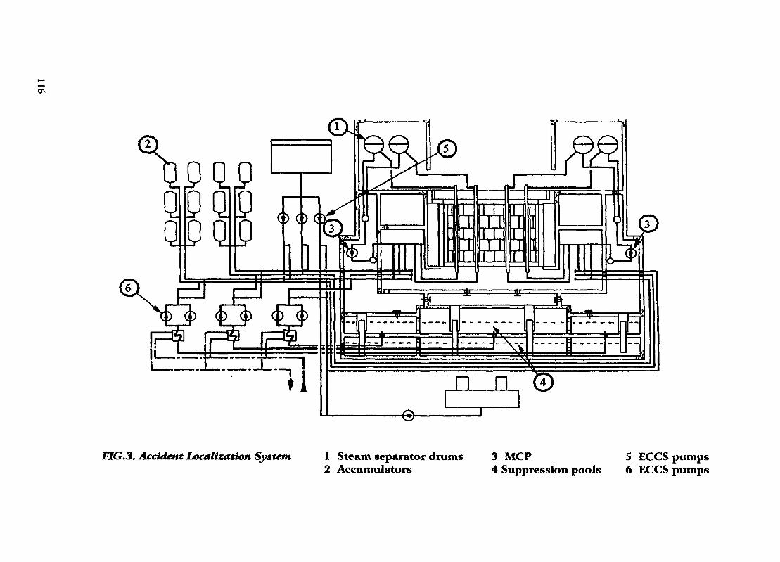
n n (4
FIG.3. Accident Localization System 1 Steam separator drums 3 MCP 5 ECCS pumps2 Accumulators 4 Suppression pools 6 ECCS pumps

ABBREVIATIONS
ACS accident confinement systemALS accident localization systemAM accident managementDBA design basis accidentDH discharge headerECCS emergency core cooling systemEOF emergency operating procedureGDH group distribution headerINSAG International Nuclear Safety Advisory GroupLWR light water reactorMCP main coolant pumpMDL maximum design limitPSA probabilistic safety assessmentPSC probabilistic safety criteriaRBMK light water cooled, graphite moderated, channel type reactor (Soviet design)SOL safe operation limitsSRV safety/relief valve
REFERENCES
[1] INTERNATIONAL ATOMIC ENERGY AGENCY, Basic safety principles fornuclear power plants, a report by the International Nuclear Safety Advisory Group,Safety Series, 75-INSAG-3, Vienna, 1988.
[2] M.D. Zentner, e.a., N Reactor Level 1 Probabilistic Risk Assessment, Prepared forthe US Department of Energy, Westinghouse Hanford Company, Richland,Washington 99352, May 1990.
[3] Ontario Hydro, Darlington NGS Probabilistic Safety Evaluation, Summary Report,December 1987.
[4] INTERNATIONAL ATOMIC ENERGY AGENCY, Report of the IAEA consultantsmeeting on probabilistic safety assessment for Leningrad NPP, 11-15 July 1994,Sosnovy Bor, Russia, IAEA-RBMK-SC-017, Vienna, 1994.
[5] Soederman, E., Johanson, G., Shiversky, E., Zheltobriuch, G., Bagdonas, A., TheBarselina Project, Phase 3, Summary Report, June 1994.
NEXT PAQB(S)left BLANK i 117

J. Andreev
P.J.T. Bakker
R.N. Bhawal
V. Cammarata
A. D'Eer
S. Gibelli
R. Gubler
S.K. Haware
G. Horvath
M. Kajimoto
I. Kalinkin
See Darl Kirn
L. Kucera
B. Kujal
H. Loeffler
R. Lopez-Moronez
Z. Meisami Azad
R. Otero
D. Serbanescu
S. Shahid
C.H. Shepherd
E. Shubeiko
M. Sobajima
V. Sopira
V. Soucek
I. Turcu
Yi Zeng
LIST OF PARTICIPANTS
Forum fur Atomfragen, Vienna, Austria
KEMA, Arnhem, Netherlands
Nuclear Power Corporation, Mumbai, India
Italian National Agency for Environmental Protection, Rome, Italy
TRACTEBEL, Brussels, Belgium
Comissao Nacional de Energia Nuclear, Rio De Janeiro, Brazil
International Atomic Energy Agency, Vienna(Scientific Secretary)
Bhabha Atomic Research Centre, Trombay, India
Institute for Electrical Power Research VEIKI, Budapest, Hungary
Nuclear Power Engineering Corporation, Tokyo, Japan
Atomenergoproekt, Moscow, Russian Federation
Korea Atomic Energy Research Institute, Taejon, Republic of Korea
Temelin NPP, Temelin, Czech Republic
Nuclear Research Institute Rez, Rez, Czech Republic
Gesellschaft fur Anlagen- und Reaktorsicherheit, Cologne, Germany
Comision Nacional de Seguridad Nuclear y Salvaguardias, Mexic City,Mexico
Atomic Energy Organization of Iran, Tehran, Islamic Republic of Iran
JJBERDROLA, Madrid, Spain
National Commission for Nuclear Activities Control, Bucharest, Romania(Chairman)
Pakistan Atomic Energy Commission, Chashma Nuclear Power Project,Islamabad, Pakistan
Health and Safety Executive, Nuclear Installation Inspectorate, Bootle,United Kingdom
RF Gosatomnadzor, Moscow, Russian Federation
Japan Atomic Energy Research Institute, Tokai-mura, Ibaraki-ken, Japan
RELKO Ltd., Bratislava, Slovakia
State Office for Nuclear Safety, Prague, Czech Republic
Institute for Nuclear Research, Pitesti, Romania
Atomic Energy Control Board, Ottawa, Canada
119