ya circuiit packai ~leak d~oyle, jr. · tegrated circuiit packai inir~it us~g ~leak detection...
TRANSCRIPT

AM_
yA s oir C ! TEGRATED CIRCUIIT PACKAi INir~iT
US~G ~LEAK DETECTION TECFNIQU!:-
Edgor A. D~oyle, Jr.
T C'I L REPORT NO. RADTP',Q-0?-a2May 1967
'hs dtocumeal. has beer, approved f,11c release an~d Rae; its distribu--is unblmted.
r;DE-65.-1O0
Rom Air Oevafoptnt CenterAir Force Systems COnMMnd
Griffiss Air Force Base, New York

ANALYSIS OF INTEGRATED CIRCUIT PACKAGE INTEGRITYUSING HELIUM LEAK DETECTION TECHNIQUES
Edgar A. Doyle, jr.
This document has been approved forpublic release and -sale; its distribu-.tiont is unlimited.
AFDE-65-1 0

FOREWORD
This report covers work performed under RADC Discretionary Fund ProjectDE-65-10, entitled: "Reliability Evaluation Techniques for Integrated Circuits."
The author wishes to thank Mr. Gerald G. Sweet who prepared the integrated cir-
cuit package metallurgical cross sections and photographs, and Messrs. John F.Carroll, Jack S. Smith, and Vincent C. Kapfer for technical discussions related to thetheoretical gas flow analysis presented in the report.
This report has been reviewed and is approved.IApproved: EDGAR A. DOYLE, JR.
Reliability Physics SectionReliability Branch
Approved: f i BETHief, EAIieering Division
FOR THE COMMANDE&W Aa -IRVN GJI . GABELMANChief, Advanced Studies Group
F
15p
Ii

ABSTRACT
Cur-"et integrated circuit packaging techniques, a compilation of applicablepackage hermeticity testing techniques, and the required theoretical fluid flow back-ground necessary to evaluate integrated circuit package integrity, are presented. Thebasic types of integrated circuit packages are described with the emphasis placed ondefects in package construction and hermetic sealing t chniques which can influencepackage integrity. A general description of standard hermeticity tests is given, andLtheir inherent limitations, when used in determining integrated circuit package leakrates, are discussed. The helium leak detection system and test procedures forpackage leak rate measurements (dV/dt-std. cc/He/sec. ) are described. A completereview and analysis of the classical steady state helium gas flow rate equations aregiven. The time dependenco corrections to the classical flow laws, required when anenclosed volume (e. g. and IC flat pack) is imposed on the system are derived andapplied to the helium leak detection technique. The analysis includes a detailed deter-mination of equivalc .t hole dianeters based on the measured package leak rate. Theimnportance of obtaining a hermetically sealed package with reference to integratedcirnuit reliability is then discussed.
In the classical steady state gas flow analysis, the derivation of the free-molecularflow rate ! 1w is noteworthy. The specific approach taken in deriving this gas flow ratelaw allows a determination of the variation in the molecular flow ra.e magnitude atpoints within a cross-sectional plane of a cylindrical tube. This variation in molecularflow rate has been implied in the literature; however, the functional dependence ofdN/dt on the radial distance from the tube axis has not previously been explicitly de-termined.
iii/iv
TABLE OF CONTENTS
iiSection Title Page
I INTRODUCTION .. .. ........... ............... 1
II INTEGRATED CIRCUIT PACKAGES ................. 31. Package Requirements ................... .... 32. Package Types . ............... . ........ .. 3
3. Reliability Considerations ....... 0.... ........... 6
:11 PACKAGE INTEGRITY TECHNIQUES FOR INTEGRATEDCIRCLITTS (HERM~ETICIT-il ....................... 81. Gross Leak Test . .. ........................ 8
a. Alconox-Water Solution Test .............. o...... 8b. Polyethylene-Glycol Test .. *" **......... ..... 9c. Technique for Increasing the Leak Detection Sensitivity
of Gross Leak Tests (a) and (b) ................ 9d. Air Pressure BomubTest..................... 9e. "Joy Bomb" Tast ................ ............ 10
2. Fine Leak Tests ......... o................. 10a. Radiflo Leak Test .................... ... 10b. Helium Leak Test................. ............... 10
IV DESCRIPTION OF HELIUM LEAK DETECTION TECHNIQUE.........121. Hlelium Pressure Bomb.............. ................ 132. Nitrogen Gas WVash.................................... 133. Leak Rate Measurcnent Using the Veecr) Helium Leak
Detection Sstem............... .............. . .. 13
V GENERAL EQUATIONS DESCRIBING GAS FLOW THROUGH1 LONG CYLINDRICAL TUBES, APPLICABLE IN THEDETERMINATION OF INTEGRATED C IRC UIT PACKAGELEAK RATES . .. .... ............... o o .. ........ . 17
VI GAS FLOW RATE TIE DEPENDENCE CORRECTIONS o......19
VII HELIUM,% LEAK TEST ANALYSIS AND DETERIMINATrION OFEQUIVALENT HOLE DIAIMETER BASED ON THE IMEASUREDPACKAGE LEAK RATE WITH hIELIUM.\ BOMB PRESSUREAND TIIE SPECIFIED............. . ....... ... 30
i. hyscalProertesof the Fla Pack Integrated CrcuitPackage Required for the Theoretical Hielium Leak TestAnalysis ............................... o 30
$v
TABLE OF CONTENTS (Continued)
Section Title Page
2. Analysis of the Steady State Viscous, Diffusional, andFree-Molecular Gas Flow Rates ....................... 30
3. Analysis of the Time Dependent Viscous, l)iffusional, andFree-Molecular Gas Flow Rates ...................... :;7
4. Determination of Equivalent Leak Hole Diameter ........... 42
VIII CONCLUSIONS AND RECOMMENDATIONS .................. 45
APPENDIX. Derivation of the Classical Equations DescribingFluid Flow through Long Cylindrical Tubes, Appl'cable in theDetermination of Integrated Circuit Package Leak Rates ......... 47 j1. Poiscuille's Laws of Viscous Fluid'Flow for Liquids and
Gases . . . . . ...... ....... ................... 47 I2. Diffusional Flow Laws of a Gas ...................... 543. Freq.-Molecular Flow Laws of a Gas ............ 574. Summary of Equations Characterizing Fluid Flow
Through a Cylindrical Tube Including Definition ofTerms .................................. .. . 64
5. Analysis of the Classical Steady State Gas FlowEquations ...................................... 6 5
REFERENCES ..................................... 68
vi

LIST OF ILLUSTRATIONS
Figure Title Page
1 Integrated Circuit Packages: a. TO-type and Flat Package,b. Package Cross-Sectional Diagrams, c. MetallurgicalSctions ..................... .................... 5
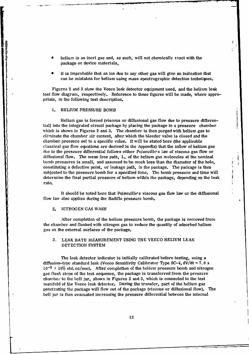
2 Package Leak ,,ate Measurement Flow Diagram Illustrating.a. Helium Pressure Bomb, b. Nitrogen Flush, c. VeecoHelium Leak Detector Showing Mass Spectrometer,d. Readout Electronics ............................... 14Veeco Mass Spectrometer Leak Detector and Helium Pre.,ireBomb Units used for Integrated Circuit Hermeticity Testing ....... 15
4 Molecular Mean Free Path L of Helium and Air as a Ftuactionof Pressure ........... .. .............. . 32
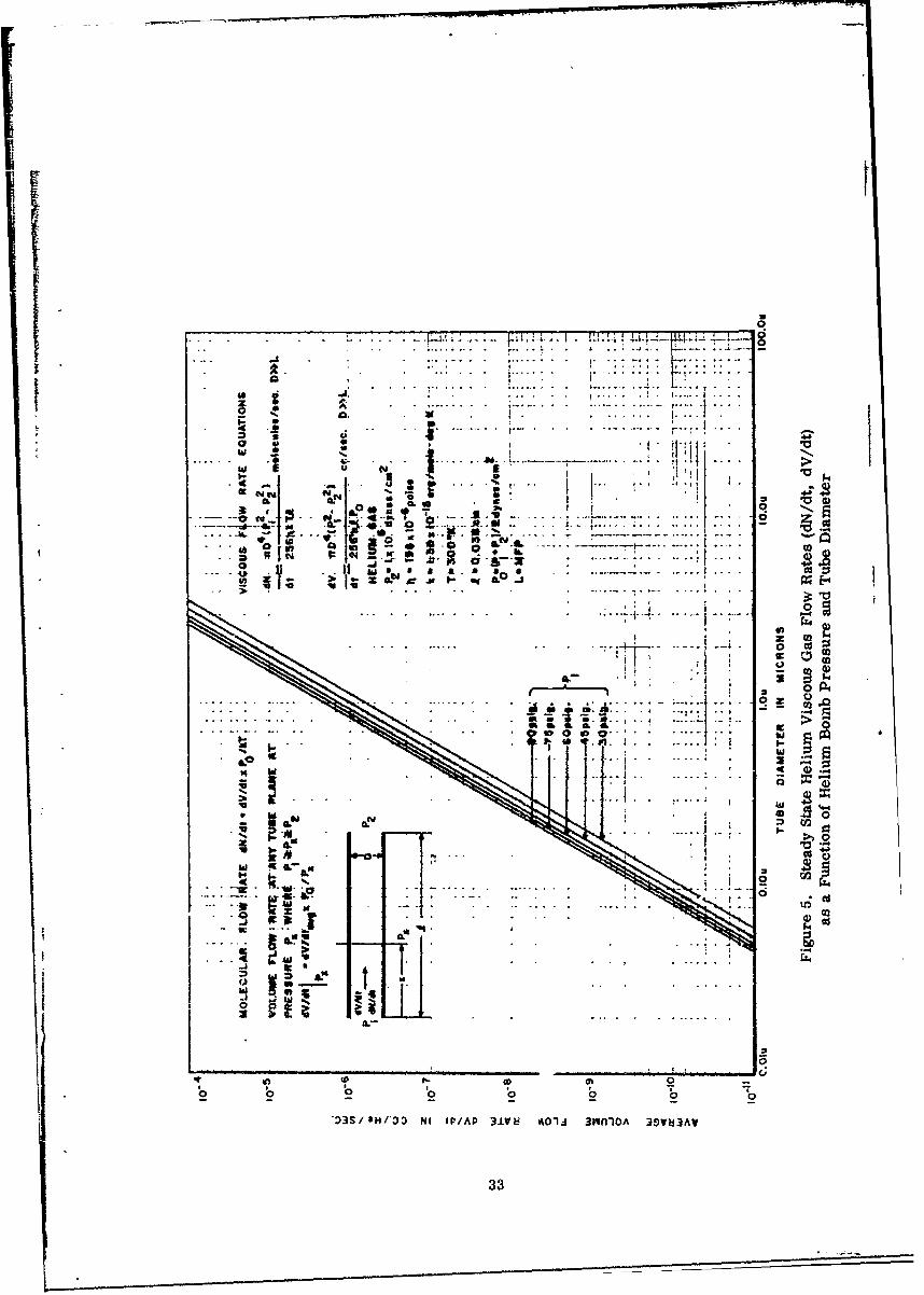
5 Steady State Helium Viscous Gas Flow Rates (dN/dt, dV/dt)as a Function of Helium Bomb Pressure and Tube Diameter ....... 33
6 Steady State Helium Diffusional Gas Flow Rates (dN/dt, dV/dt)as a Function of Helium Bomb Pressure and Tube Diameter ...... 34
7 Steady State Helium Free-Molecular Gas Flow Rates (dN/dt,dV/dt) as a Function of Internal IC Package Pressure andTube Diameter ..................................... 35
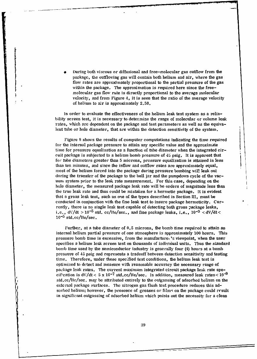
8 IC2 Package Internal Helium Partial Pressure Due to Viscous-Flow as a Function of Helium Pressure Bomb Time forSeveral Hole Diameters ............................
40A-1 Force Diagram for Fluid Flow Through a Cylindrical Tube
Due to a Pressure Differential ............................. 48A-2 Diagram Illustrating the Frictional Force Resisting the
Relative Motion of Two Adjacent Layers of a Viscous Fluid ....... 49A-3 Diagram Used in Deriving the Diffusional Gas Flow Law
Through a Cylindrical Tube Due to a Concentration Gradient ...... 55A-4 Diagram Used in Deriving the Free-Molecular Gas Flow Law
Through a Cylindrical Tube Due to a Pressure Gradient ......... 58A-5 Graph of Flow Integral Versus x .......................... 62
vii/viii
i

SECTION I
INTRODUCTION
Extensivl research in the field of semiconductor surfaces by both the semicon-ductor industry and Government-sponsored programs (1, 2, 3, 4, 5, 6, 7. 8, 9) aas re-suited in the realization that surface effects determine, to a large extent, theelectrical characteristics of p-n junctions. Current silicon junction devices and inte-grated circuits are fabricated almost exclusively using planar technology, I. e., oxidepasslvated diffused junction structures, resulting in a significant improvement indevice reliability. In addition, these transistor structures, fabricated using theepitaxial-planar process, exhibit extremely low-junction leakage currents, have im-proved noise figure, d-c characteristics, voltage and power dissipation ratings, low-current and high-frequency gain characteristics, and switching speed when comparedwith earlier transistor structures.
Although a significant improvement in device performance has been achievedutilizing the planar technology, it has been shown that degradation of p-n junctionreverse current-voltage characteristics and transistor grounded-emitter current gain(f0) characteristics can result from inversion layer formation, where the typical failuremodes observed are an Increase (IR > IR max specification) in reverse leakage cur-rent, and a reduction in 0 (0 < 0 min specification), respectively. Various mechanismshave been identified (10) which cause semiconductor surface inversion layers including:(1) a fixed positive surface state charge at the oxide-silicon interface of an uncon-taminated thermal oxide; (2) alkali ion contamination within the silicon dioxide whichcan migrate and redistribute at elevated temperatures; (3) a positive space-chargewithin the oxide due to exposure to ionizing radiation; (4) ionic charge on the surfaceof the oxide i. e. ionic contamination in a package where there exists a given level inparts per million (ppm) of moisture content which increases the mobility of the con-taminant in the presence of an electric field; and (5) a strong electric field producedby a voltage applied to a metal field plate on the oxide surface over the silicon.
Field-induced junctions, (FIJ), and surface charge migration on the oxide surfaceusing gated diode structures have been investigated by Fairchild Semiconductor, inwork sponsored by the Rome Air Development Center under contract AF 30(602)-3776. (9)They have demonstrated the conditions required to induce surface depletion and inversion(field-induced junction) and the relationship between the rate of depletion or Inversionlayer growth due to ion migration and the sheet resistivity of the oxide surface. Further,Grove and Fitzgerald, (10) using a gated diode structure, have demonstrated the con-ditions required to generate large channel currents.

The discrete elements (that is, resistors, capacitors, diodes, and transistors)comprising a monolithic integrated circuit are interconnected using a metallization
pattern consisting of conducting lands or strips of aluminum or molybdenum-golddeposited on the oxide surface. The connections to discrete elements are made bymetallic deposition through etched oxide windows and subsequent alloying. The metalliclands of the interconnect pattern on the oxide surface cross directly over junctions anddiscontinuities in the oxide thickness. Thus, the possible formation of field-inducedjunctions (surface inversion or depletion) in integrated circuits is readily apparent withan applied potential to the metallic lands. In addition, since the oxide sheet resistivity,which governs the rate of inversion layer growth away from the land, is a function ofthe moisture content and contamination within the package, the importance of minimizingmoisture content is evident. The presence of several parts per million water contentwill reduce the oxide sheet resistivity, thereby increasing the rate of inversion layergrowth.
Results of the Minuteman II Reliability Program, where all integrated circuit
devices were subjected to hermeticity tests with a specified maximum allowable leakrate of 5X10 - 7 std. cc. /sec., have shown that surface-inversion type failures con-tributed significantly to the over-all device failure rate, and that a 100 per cent powerburn-in screen was both necessary and effective in reducing integrated circuit surfaceinversion failures. Results of the Component Quality Assurance Program (CQAP) underthe Minuteman H Program, where reliability tests were designed to accelerate specificfailure mechanisms and generate device failures, have shown that surface inversion is
one of the dominant failure mechanisms observed in integrated circuit devices.
Semiconductor surface-inversion is observed in integrated circuits during relia-bility stress testing even after passing hermeticity tests. These tests indicate thepresence of ionic contamination and moisture content within the package after final sealor bulk oxide contamination. Since the rate of inversion layer formation due to surfaceion migration is a function of the oxide sheet resistivity which, in turn, is a function ofthe contamination and relative humidity within the package, it points out the require-ment for a hermetically-sealed integrated circuit package. It also indicates that theultimate device reliability is related to the degree of package hermeticity. 1lhis fact,in itself, justifies extensive IC package hermeticity screen tests for insuring high-reliability devices.
The following sections describe the standard integrated circuit packages andhermeticity test techniques used for package leak detection and determination of leakrate magnitude. The classical fluid flow equations and derivations are included ii theAppendix. The time-dependent flow equations developed in Section VI are used todetermine the sensitivity of the helium system over a range of package leak rates. Amethod for equivalent leak hole diameter determination based on a measured packageleak rate is reviewed.
The integrated approach taken here results in a compreh insive examination ofhermeticity testing techniques used for evaluating IC package integrity.
2

f S ESECTION D
INTEGRATED CIRCUIT PACKAGES
1. PACKAGE REQUIREMENTS
in general, integrated circuit packages are designed to meet a number of specificrequirements, based on anticipated environmental ccnclitions, with the most commonrequirements listed below:
a. The package must provide a mechanically stable device enclosure so reliabilityscreen tests such as vibration, drop shock, centrifuge, and thermal shock,which are intended to simulate operating conditions, do not affect the operationalcharacteristics of the device.
b. The package must provide electrical feedthroughs from the internal deviceitself to the package externals which are electrically insulated from the packagefor supplying power to the circuit.
c. The package must provide for heat transfer away from the device, within thepackage, since device parameters change significantly with temperature.
d. The package must be corrosion-resistant to external environments.
e. The package must be hermetic to prevent exposure of the internal device tohigh relative humidity ambients, etc., since the electrical parameters of thediscrete elements comprising the integrated circuit can change value ordegrade when exposed to this type of environment.
'. The package must provide a light shield since semiconductor junction deviceparameters are light-sensitive.
g. The package must isolate the internal device from external radiation and, also,in specific instances, act as a shield to prevent the internal circuit fromradiating to and adversely affecting the operation of other external circuitry.
2. PACKAGE T1 PES
The hermetic packages most commonly used for integrated circuits, whicn are de-signed to meet the requirements previously discussed, are the TO-type p'ckages, andflat packages.
3

The TO-type package is made entirely of metal (I. e., gold-plated Kovar), wherethe leads are insulated from the metal package with glass, forming glass-to-metalseals. The Kovar header eyelet can be either a-solid or recessed base type. Thesilicon die attach is accomplished using the gold-silicon eutectic formed by alloying,at an elevated temperature, the silicon die with the gold in the header. Interconnectionof the integrated circuit die and the package leads is performed using various bondingtechniques. The most common techniques are thermocompression bonding, ultrasonicbonding, and parallel-gap welding. Final sealing is accomplished by welding the canto the header.
The flat package construction varies from manufacturer to manufacturer. Generally,the leads and all metal parts of the package are gold-plated by the manufacturer. Thepackage base and lid material may be metal (e. g., Kovar), ceramic (e. g., alumina(A1 2 0 3 ) and beryllia (BeO)), or glass (glass composition varies between manufacturers).The package wall material may also be metal, ceramic, or glass where the base andwall can either be a single unit or separate units. The leads are insulated from thepackage with glass employing glass-to-metal sealing techniques. The silicon die attachto the package base is made, using either a eutectic or glass seal, aepending on thebase material, i. e., a eutectic preform is used for metal base packages and a glasspreform for ceramic and glass base packages. The interconnection of the silicon dieto the package leads is accomplished, using the bonding techniques previously mentioned,I Final sealing is accomplished using either a eutectic (e. g., gold-silicon, gold-ger-manium, or gold-tin) or low temperature glass preform (e. g., polyceram), which ispositioned between the lid and wall. It is subsequently heated until the eutectic, or glass,flows and wets the surfaces to be joined, forming the hermetic seal.
Figure 1 shows the comploted TO-type and flat package assembly. Package crosssecilons with component parts, materials used, and hermetic seals are indicated.Metallurgical sections of typical hermetically-sealed packages with package components,materials, and seals are also shown. The flat package construction of the integratedcircuit test vehicle, used under project DE-65-10, is similar to the flat package con-struction shown in Figure 1. The major differences are: (1) a metal base is used and(2) the gold-plated Kovar leads inside the package are a formed cantilever such that thelead welding pad at the end of the cantilever is elevated above the lead frame and thesilicon die surface.
A more complete description of package construction, including the various metal,eutectic, ceramic, and glass materials used, and hermetic sealing techni qes, is givenin RAD'7-TR-65-61, July 1965, "Microelectronic Packaging Concepts." (1)
4

TO-2 fpc Packa&1e !'!at Packa cs
(a)
Kovar LeAWcan oaLi
(b)
Glas-ta-Fbva Byeet LSilicon DieMetl SalsGlass Seal
Glass-to-f-etal. and Glan s-to-Ceramic Sealr
Novar Leadi
/Silicon DieBilicon Die Koa i and 1WI1
Kovar IeAd
Figure 1. Integrated Circuit Packages: a. TO-type and Flat Packageb. Package Cross-Sectional Diagrams c. Metallurgical Sections
5

I
The package manufacturer visually inspects the package parts for mechanical de-
fects, performs electrical insulation tests, and checks the hermetic seals, using eitherthe helium or the Radiflo leak test. Thus, the hermeticity tests performed on thepackage after final seal is made will generally indicate the quality of the lid-to-package-wal7 seal. However, the possible damage to the manufacturers' package hermeticseals, due to improper handling, silicon die attach, lead bonding, and final seal opera-tions cantiot be overlooked.
3. RELIABILITY CONSIDERATIONS
In general, as previously pointed out, integrated circuit reliability, from thepackaging standpoint, is dependent upon the degree of package hermeticity. The criticalmanufacturing process common to the described packages, which determines theultimate degree of hermeticity, is the formation of hermetic glass-to-metal or glass-to-ceramic seals. The quality of the final seal of the package also determines thedegree of package hermeticity. Generally this process is well-controlled, and does
not involve the more critical process of hermetically-sealing a large number of leadswhile maintaining electrical lead insulation between the various parts of the package.
The factors affecting both the quality of the initial seals and the degradation of theseals, when exposed to various environmental conditions such as high temperatures,vibration, thermal shock, etc., are listed below and include:
a. Differences in the thermal coefficient of expansion between the metal andglass or ceramic and glass. A slight mismatch in the thermal coefficient ofexpansion between the metal and glass is sufficient to cause a separation ofmetal and glass at some temperature. To prevent separation of metal andglass, an oxide is grown on the metal surfaces. The fusing then results in acontinuous transition from metal, to metal oxides, to metal oxides in glass,to glass. The commonly used ceramics are metal oxides, and the transitionis from ceramic, to ceramic in glass, to glass.
b. The uniformity of grown metal oxide buffers required to prevent the separationof metal and glass due to slight differences in the thermal coefficient of ex-
pansion. In the case of glass-to-metal seals, if thin spots in the grown oxideare present, upon fusing, it is possible for the oxide layer to be completely
dissolved in the glass, thus eliminating the oxide buffer resulting in a leakyseal.
c. Material cleanliness (removal of oxides, oil, or particle contamination) during
processing, in particular, of the metal surfaces prior to oxide growth. The
cleanliness of the metal surface prior to oxidation and the control of theoxidation process will determine the oxide thickness uniformity required fora high quality hermetic seal. In general, any contanination on the surfaces
of the material, during sealing processes will produce a nonuniform seal be-
tween the two surfaces.
6

d. The quantity or volume of glass surrounding the leads and metal or ceramicsurfaces. Further, a greater volume of glass surrounding the leads and in
[ contact with other metal or ceramic surfaces will insure a mere reliable seal.
Another major problem area in the hermetic sealing process is void formationwhich can be caused by the outgassing of gas pockets within the materials atelevated temperatures (fusing temperature). The outgassing of packagematerials during reliability stress testing at elevated temperatures is a possiblesource of contamination which could be detrimental or degrading to deviceoperational characteristics.
Flexing the gold-plated Kovar leads could fracture the glass-to-metal seal,resulting in a leaky seal at that point. It is conceivable that reliabilityaccelerated testing at elevated temperatures could degrade package hermeticityby destroying the hermetic seals at weak points in the package.
The preceding discussion delineated the requirements necessary for fabricatinga hermetic integrated circuit package and some conditions under which thepackage hermetic seals could be destroyed. The following section will describethe various techniques used in determining the degree of hermeticity of apackaged circuit, i. e. after the silicon die attach and final sealing processeshave been performed.
7!
'1 4

. . ..- .......-.. . o- = - - - . . - "
SECTION II3
PACKAGE INTEGRITY TECHNIQUES FOR INTEGRATED CIRCUITS (HERMETICITY)
Hermeticity testing of integrated circuits can be broken down into the three maincategories as listed below:
" Class A Leaks - Leak Rate < 10- 9 cc/sec.
o Class B Leaks - Leak Rates from 10- 5 cc/sec. to 10 - 9 cc/sec.
* Class C Leaks - Leak Rate >10- 5 cc/sec.
In general, an integrated circuit package is considered hermetic if it has a leakrate less than , X 10 - std. cc/sec. The hermeticity tests used for determining ICpackage leak rates fall in two major classes as listed below:
* Gross Leak Tests - Leak Rates > 10- 5 cc/sec.
0 Fine Leak Tests - Leak Rates < 10- 5 cc/sec.
There are various measurement techniques used in the semiconductor industry formeasuring leak rates in different types of IC packages in the above two classes. Theseare described in the following subsections.
1. GROSS LEAK TESTS
a. Alconox-Water Solution Test
This test is conducted by immersing the package in a 90 0 C alconox (wettingagent) water solution for 15 seconds, observing it with a low power n'icroscope for con-tinued bubble formation from any point on the external package. The principle of thistest is that the expansion of the gas, rcsulting in a pressure increase within the packagedue to the elevated temperature, will force part of the gas out of the package through adefective seal. A continuous stream of bubbles indicates a gross leak in the package.This test is inexpensive and requires a minimum of equipment and time. However, thesolution can enter the package through a seal defect and damage the device.
8

b. Polyethylene-Glycol Test
This test is performed by placing the unit in hot polyethylene-glycol at1500C and, again, observing with a low-power microscope for continued bubble forma-tion. The test principle is identical with the alconox-water test, and a steady streamof bubbles from any point on the package is interpreted as a gross leak. Again, thistest is inexpensive and requires little equipment and time. However, damage to theunit can result from the inflow of the liquid into the package.
c. Technique for Increasing the Gross Leak Detection Sensitivity of GrossLeak Tests (a) and (b)
The method used for increasing the leak detection sensitivity of the alconox-water solution test at 90 0 C and the polyethylene-glycol test at 1500C consists of sub-merging the package into either of the test solutions for several minutes. During thisprocedure the existing pressure differential forces part of the package internal gas outof the package. The partial outflow of gas thus creates a partial vacuum within thepackage if the package and internal gas are instantaneously returned to ambient temp-erature and atmospheric pressure exists outside the package. This condition can besimulated by removing the package from the test solution and immediately submergingit into methyl alcohol at 250C and atmospheric pressure for several minutes. If agross leak exists, alcohol will be forced into the package due to the pressure differential,i.e., A P = atmospheric pressure-internal package pressure, until pressure equilibriumis reached at the ambient temperature of 250C. The package will then contain air atatmospheric pressure and liquid alcohol. The package is then removed from the alcoholbath and resubmerged into the alconox-water solution or polyethylene-glycol. Thetemperature of either test solution exceeds the boiling point of the methyl alcohol(64. 50C) within the package causing vaporization. The vaporization of the liquid alcoholin the package at the elevated temperature res-Ats in a higher pressure differential thanthat existing when the package initially contains gas at one atmosphere pressure. Inaddition, the liquid alcohol will continue to vaporize at -, definite rate such that thepressure differential will exist for a longer time duration. The increased pressuredifferential existing over a longer time interval thus increases the detection sensitivityof Gross Leak Tests (a) and (b). Using this technique, again a continuous stream ofbubbles emanating from the package is interpreted as a gross leak.
d. Air Pressure Bomb Test
This method oi gross leak detection uses alcohol at room temperature.The unit under test is placed in a high-pressure (45 pounds per square inch) air atmos-phere for four hours. It is then returned to ambient pressure, immersed in alcohol,and observed with a low-power microscope. The basic test principle is the inflow andoutflow of air due to a pressure differential. Again, a steady stream of small bubblesis interpreled as a gross leak. Alcohol is chosen as the immersion medium because itis a solvent for any organic material which may clog seal leaks. Also, the alcohol
9

I
will not cause device damage. This technique has overc-me the major disadvantagesassociated with the polyethylene-glycol and alconox-water solution test, but requiresmore time and equipment.
e. "Joy BombY Test
This test detects the presence of an ionized low viscosity solution whichis forced into a leaky package under pressure. The typical test consists of a one-hoursubjection of devices to 100 psig using a solution of water and "Joy", or various otherdetergents. Following this test, units are tested on an oscilloscope or transistor curvetracer for mobile hysteresis or reverse leakage current. A significant increase in thereverse leakage after Joy Bomb indicates a gross leak. This test requires time andequipment and, since the solution enters the package, damage to the device usuallyoccurs.
2. FINE LEAK TESTS
a. Radiflo Leak Test
The Radiflo unit is an instrument used for measuring leak rates of en-closed volumes between 1 x 10⁻⁵ std.cc/sec. and 1 x 10-11 std. cc/sec. The systemuses a radioactive gas (Krypton 85) as a tracer. The test consists of subjecting asealed IC package to a mixture of a carrier and radioactive Krypton gas under pressure(nominally 100-200 psig) for a specified time. The maximum pressure the package canwithstand must be determined so that as high a bomb pressure as possible can be usedto minimize the bombing time. The IC packages are placed in the bombing chamberwhich is then evacuated and subsequently backfilled with the carrier gas and radio-active Krypton gas mixture to a specified pressure for a specified time. The radio-active and carrier gas mixture is then removed from the chamber by a series of"clean" gas purges, or washes, which also remove any adsorbed gas on the surfaces
of the package. Each packaged device is then placed into the well of a scintillationcounter, and a calibrated reading in terms of std. cc/sec. is obtained from the amountof radioactive gas within the package. The major advantage of the Radiflo leak testis that large quantities of devices can be bombed simultaneously, and individual de-vice leak rate measurements can be performed in a minimum of time as compared withthe helium leak test system. The disadvantage of Radiflo is its inability in detectingleak rates greater than 10-5 std. cc/sec. If the hole in the seal is large, allowing grossleakage (t> 1 x 10⁻⁵ std. cc/sec. ), the radioactive gas can leave the package throughthe same-defective seal and escape detection.
b. Helium Leak Test
Hermeticity testing of integrated circuit packages, conducted at RADC underproject DE-65-10, uses the Veeco helium leak test system with helium gas as thetracer fluid. Thle system is capable of measuring package leak rates in the I x 10-5
10

to 1 x 10- 10 std. cc/sec. range. The test corsists of placing a sealed integrated cir-ci~it package in a pressure chamber, which is subsequently purged with pure helium gasto eliminate the chamber air content, and then pressurized to a specific helium bombpressure. The package is bombed at this pressure for a given length of time (nominallytwo to five hours at 45-60 psig), removed from the chamber where the external packagesurface is flushed with dry nitrogen gas to remove adsorbed helium gas, and then placedin a bell jar which is then evacuated. This allows the detection of part of the helium gasflowing out of the package by a mass spectrometer tuned for helium. The test variables,(1) helium bomb pressure and time duration, (2) infornation such as Veeco helium leakdetector calibration, (3) time of measurement for leak rate determination, (4) charac-teristic curves of detected leak rate versus time during leak test under vacuum condi-tions, and (5) the limits of system detectability (minimum and maximum detectable leakL rates), must be determined to evaluate integrated circuit package integrity using thehelium leak detection system. This method of leak detection and the determination of
test variables are presented in detail in the following sections.
I4
b 11

SECTION IV
DESCRIPTION OF HEIUM LEAK DETECTION TECHNIQUE
In general, the basic principle underlying all methods of leak detection of anenclosed volume, as evidenced from the hermeticity tests described in the previoussection, involves the passage or transfer of a tracer fluid (a liquid or gas) externalto the volume, through a leakage path. This leakage path or paths can assume variousgeometrical configurations, and its existence is verified by detection of the tracerfluid which penetrated the enclosed volume. The basic difference between the Radifloand the helium leak test lies in the method used for detection of the tracer fluid whichis forced into the enclosed volume or package. In the Radiflo techniPe, a radiationcount of the package, after pressure bombing, is made by employing a scintillationcounter. The counts per minute readout obtained Is a direct measure of the quantityof radioactive gas (Krypton 85) within the package, which is a function of the packageleak rate. The measured radiation count is converted to an equivalent volume leakrate and recorded in std. cc/sec. Thus, the Radiflo leak test technique requires onlythat the radioactive gas enter the enclosed volume for detection and leak rate measure-ment. In the helium technique, again, the tracer gas (helium) is forced into the pack-age by a pressure bomb cycle. However, the mass spectrometer detection techniquerequires the outflow of the helium gas within the package into the mass spectrometerfor detection and leak rate measurement. Thus, the helium technique requires boththe inflow and subsequent outflow of the tracer gas for package leak rate determination.
The following description of the helium leak test technique will emphasize the orderof the test sequence, the equipment used during each test step, and, where applicable, thetype of fluid flow the gas undergoes during specific test procedures. This can then becompared with the gas flow characteristics during the Radiflo test sequence.
Some of the basic considerations in the selection of helium for use as the tracergas in the mass spectrometer type leak detection technique should be mentioned here:
A the rate of diffusion of helium gas through a leak, due to its small mass,is greater than that of any other gas, with the exception of hydrogen.
* the molecular diameter of helium is small,
helium occurs in the atmosphere to the extent of only one part in 200, 000parts of air,
-2
I -
0 helium is an inert gas and, as such, will not chemically react with thepackage or device materials,
0 it is improbable that an ion due to any other gas will give an indication thatcan be mistaken for helium using mass spectrographic detection techniques.
Figures 2 and 3 show the Veeco leak detector equipment used, and the helium leaktest flow diagram, respectively. Reference to these figures will be made, where appro-priate, in the following test description.
1. HELIUM PRESSURE BOMB
Helium gas is forced (viscous or diffusional gas flow due to pressure differen-tial) into the integrated circuit package by placing the package in a pressure chamberwhich is shown in Figures 2 and 3. The chamber is then purged with helium gas toeliminate the chamber air content, after which the bleeder valve is closed and thechamber pressure set to a specific value. It will be stated here (the applicableclassical gas flow equations are derived in the Appendix) that the inflow of helium gasdue to the pressure differential follows either Poiscuille, s law of viscous gas flow ordiffusional flow. The mean free path, L, of the helium gas molecules at the nominalbomb pressures is small, and assumed to be much less than the diameter of the hole, fconstituting a defective point, or leakage path, in the package. The package is thensubjected to the pressure bomb for a specified time. The bomb pressure and time willdetermine the final partial pressure of helium within the package, depending on the leakrate.
It should be noted here that Poiseuille's viscous gas flow law or the diffusionalflow law also applies during the Radiflo pressure bomb.
2. NITROGEN GAS WASH
After completion of the helium pressure bomb, the package is removed fromthe chamber and flushed with nitrogen gas to reduce the quantity of adsorbed heliumgas on the external surfaces of the package.
3. LEAK RATE MEASUREMENT USING THE VEECO HELIUM LEAKDETECTION SYSTEM
The leak detector indicator is initially calibrated before testing, using adiffusion-type standard leak (Veeco Sensitivity Calibrator Type SC-4, dV/dt = 7.0 x10- 8 1 10% std. cc/sec). After completion of the helium pressure bomb and nitrogengas flush steps of the test sequence, the package is transferred from the pressurechamber to the bell jar, shown in Figures 2 and 3, which is connected to the testmanifold of the Veeco leak detector. During the transfer, part of the helium gaspenetrating the package will flow out of the package (viscous or diffusional flow). Thebell jar is then evacuated increasing the pressure differential between the internal
13
r L2
0 3d
o v ci d-
to =
~co
A.A
14

494
V2)
4.J
00
4-1-
'o.
34 -3
C2
al-
OOGGG0
15

/I
and external of the package, the magnitude of which is determined by the gas pressureinside, and tb,, vacuum pressure outside the package. The flow of helium gas throughthe leak path in this case can follow the laws of viscous, diffusional, or free-molecularflov depending on the pressure (refer to Section VII-1). The mean free path, L, of the
helium gas molecules increases with decreasing pressure, and at relatively low pres-sures (P <104 dynes/cm2) and high vacuum pressures (10-5 to 10-6 Torr range), themagnitude of L of the gas molecules will exceed the leak or hole dipineter such thatcollisions with the surfaceo or walls of the leak path or hole, rather than intermolecularcollisions, will predominate and determine the molecular flow rate (free-molecularflow).
The helium gas molecules flowing out of the package into the bell jar pass down thetest manifold, through the test valve, and into the cold trap region (Figure 3). Approxi-mately 99 per cent of the helium gas content in the cold trap is exhausted by the diffusionpump and fore-pump system, the remainder of the gas passing through the Vee-tube portdirectly into the Vee-tube for detection. The Vee-tbe is essentially a mass spectrom-eter peaked for helium detection (Figure 3). The remaining vacuum and elect.,onicequipment in the system are required for maintaining the proper atmospheric conditionsfor optimum mass spectrometer operation and electrical readout, respectively.
The helium and other gas molecules entering the Vee-tube become positivelycharged ions by bombardment with electrons emitted from a tungsten filament. A positivepotential repeller grid repels the ions through the slit forming an ion beam. The beamis accelerated by an electric field and passes through the ion focus plates. The ion
I beam then enters a transverse magnetic field (permanent magnet) which deflects thepath of the ions, where the degree of deflection is determined by the mass of the ion,
the entry velocity, and the magnetic field strength. The path of the lighter ions pre-sent, such as hydrogen, undergoes a large deflection while that of the heavier ions,such as nitrogen and oxygen, undergo only a slight deflection. A baffle plate with aslit opening is positioned in the tube and adjuste1I such that the path of the helium ionsdown the tube after deflection coincides with the center of the slit opening. All otherions pre-:,tit hit the baffle plates and thus do not reach the collector. The helium ions,however, reach the collector and are detected. The signai produced by the ion currentis then amplified and fed to the leak indicator meter for electrical readout and leakrate determination. The output of the leak indicator meter is then fed into a stripchart recorder which provides a permanent record of the package leak rate as a func-tion of time and improves the readout accuracy of the system.
The gas flow laws and equations referred to in the preceding helium leak testdescription are derived in the Appendix and summarized in the following section.
16

SECTION V
GENERAL EQUATIONS DESCRIBING GAS FLOW THROUGH LONGCYLINDRICAL TUBES, APPLICABLE IN THE DETERMINATION OF INTEGRATED
CIRCUIT PACKAGE LEAK RATES
The viscous, diffusional, and free-molecular steady state gas flow rate laws, thoughderived previously by others and referenced where appropriate in the Appendix, areincluded in this report for the sake of unity and completeness, and to °irnish the readera complete theoretical background of the laws describing gas flow through cylindricaltubes. This approach results in a sound, physical understanding of the analysis of thehelium package leak test system presented in Sections VI and VII. For the completederivations of the fluid flow laws through long cylindrical tubes, the reader is referredto the Appendix.
The gas flow equations describing the steady state volume and molecular flow ratesin terms of test parameters and package properties applicable to the helium leak detec-tor system are summarized in this section.
Viscous Gas Flow Rate Equations:
.42 p22
dV 4-(P2 -P 2 D >> LdV 1 2
dt 2567YP0!0
4 2 2dN r (P1 - 2D >>L (2)
dt 256)kTy
Diffusional Gas Flow Rate Equations:
dV LV (P 1 - P 2) D>L (3)
dt 12,fP
dN _ D2va(nI - n2 ) D>L (4)dt 12J
17

Free-Molecular Gas Flow Rate Equations:
dV r lDv a (P I- P2 ) D<L (5)
dt 12,QP0
dN x D3 a (n1 -n 2 ) D<L (6)dt 12r -
18

SECTION VI
GAS FLOW RATE TIME DEPENDENCE CORRECTIONS
In this section the most applicable steady state gas flow equations will be expandedto include the time dependence corrections required when an enclosed volume (e. g., ICflat package) is imposed on the system. This will then, constitute the basic equationsused for evaluating the sensitivity of the helium leak test system to various package
• leak rates.
The previously summarized equations are valid for steady state gas flow through acircular tube where the initial conditions at the inlet and outlet of the tube are inde-pendent of time. When the gas molecules flowing through the tube are confined to afixed volume or container at one end of the tube, the gas inflow or outflow rate, in thecase of viscous or diffusional flow (pressure differential), will decrease with time dueto the decrease in the pressure differential with time. Further, considering the free-molecular outflow case (concentration or pressure differential), the molecular flow ratewill again decrease with time since the number of molecules within the enclosed volumedecrease; with time, thus reducing the pressure differential.
It is apparent that during the pressure bomb test procedure where the viscous ordiffusional gas inflow laws apply, the inlet conditions are constant (helium bomb pres-
sure) and the outlet conditions, namely the pressure within the enclosed volume, varyresulting in a change in the gas flow rate with time. Using the same argument, it isevident that during the package transfer from the pressure chamber to the bell jar,the gas outflow rate decreases with time. Similarly, during the leak rate measure-ment test procedure where the outlet is under a constant high vacuum condition andthe free-molecular outflow laws apply, the inlet conditions, namely the gas moleculardensity and corresponding pressures within the enclosed volume, vary, which again re-sults in a change in the gas flow rate with time. The ga3 flow equations applicable tothe helium package leak rate measurement system must be further developed using theappropriate boundary conditions to include all time dependent terms such that the gasflow rate can be determined as a function of time.
In the steady state gas flow rate equations summarized in Section V, the pressureand concentration gradient, dP/dl and dn/dl, .s negative by convention and, therefore,the subscripts 1 and 2 of both the P and n terms refer to the higher and lower pressureor molecular density respectively.
19

Throughout Section VI, P2 and n2 designate the pressure and molecular densitywithin the IC package. In deriving the viscous and diffusional time dependent inflowequations (Helium Pressure Bomb) the subscript notation is consistent with that of Sec-tion V and the Appendix. Note that the viscous and free-molecular time corrected out-flow equations are derived using equations (2) and (6) of Section V respectively. Thebasic equations marked by an asterisk, while of the same form as equations (2) and (6)in Section V, do not indicate a sign change but rather, a reversal in the P and n sub-script notation. This reversal allows consistent internal package parameter designa-tion while maintaining the correct pressure and concentration gradient sign convention.
Consider the helium bomb test procedure where the time dependence of the molecu-dN dVlar E and volume - leak rate and the internal package pressure, P2 , must be deter-dt 7Ft
mined. The molecular flow rate (eq. 2, Section V) and the internal package pressurecan be expressed by:
4 2 2dN 1TD (Pl 2 - 2' nN0kT NkT
dt 25617kTy 2 V c V Cwhere:
I wheD = tube diameter
P1 = Helium Bomb pressure
P = Internal IC package pressure2
= viscosity of tracer gas (helium)
k = Boltzmann's constant
T = Absolute temperature
= tube length
V = IC package volume! c
Now:
4P 42 2dP2 dN/dt kT D4(P 1 - P 2 ) 2 2dt V 256 nVc A(P 1 2
where
lTD4
A = ,
256 77Vc
20

II
The resulting differential equation is of the first order with variables separable. Sepa-rating variables and integrating gives:
b d 2 c/2 ~Af dtf (P12 P22 f
a o
I
where P2= initial internal package pressure
Integration and evaluation of the definite integrals where a = P2 at t = 0 and b==>P 2f
as c:>tf gives:
F (PI + P2) P2f
In (PI - 2) 0 = iA~ f
Thus:
(P1 -+ P2 (P 1 P 2 )L2APt-(1 P2 ) (P1 + )- if
0
Setting P2 = KP 1 ' some fraction of the bomb pressure where 1 > K> 0, and simplify-
ing the final expression for the internal package pressure as a function of bomb timeand pressure becomes:
(1 K)2APtf
P2f (1-K) 2APt(7
- e +j1L(1K) i
21

I
Substituting the previous equation for P2 into the gras flow rate equation, the molecu-lar flow rate as a function of bomb pressure and tir,.o re:
D 4P2(+ K) e 1f -
--N = 1 1 ~(1 K) ia)
dt 256 kTJ + K) e i -f
(1 - K)
Referring to equation (1), if the volume flow rate is measured at the package pressureP2 , then setting Po = P2 gives the volume gas flow rate at the entrance to the internalpackage volume.
1 _ _ 2APtf 2
i ~ 2AP tdV iD 4 PI2 (1 + K) e f + J
___ _(i- K) 2A- (7b)-dt =256 77 ,(1 + K)e 2AP 1t f-I7)
(1 -_ P t-I K] t
Similarly, the decrease in internal package pressure (loss of tracer gas) during
the transfer from the pressure bomb chamber to the vacuum bell jar as a functionof time can be derived again using eq. 2 of Section V as follows:
dN ir D 4(P2 - P12)
dt - 256 77kTf
and
- -'- = dN/dt-
Substitution of the expression for dN/dt into the equation for dP 2/dt, separation of
variables and integration yields:
b dP c
(P 2 2 ) =P )t
a o
22
where:
A- 25677TVc
0P2 = initial internal package pressure after helium bomb
P1 constant one atmosphere ambient pressure
St= a= KP 1 , in this case K > 1,and integrating where a = P at t = o and
b P P2 as c =:>tf gives the following expression for P2 as a function of time:
-K 1) -2AP tf
= ( -2AP t (7c)1) e If
The molecular and volume flow rate (outflow) as a function of time can be obtainedby direct substitution of the previous expression for P2 into the basic flow rate equ.tion.
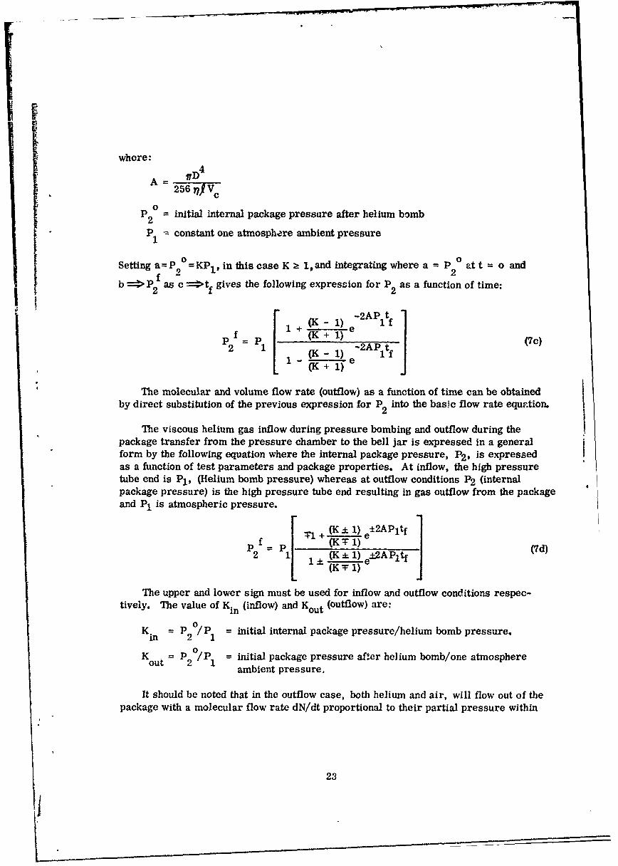
The viscous helium gas inflow during pressure bombing and outflow during thepackage transfer from the pressure chamber to the bell jar is expressed in a generalform by the following equation where the internal package pressure, P2 , is expressedas a function of test parameters and package properties. At inflow, the high pressuretube end is P1 , (Helium bomb pressure) whereas at outflow conditions P2 (internalpackage pressure) is the high pressure tube end resulting in gas outflow from the packageand P1 is atmospheric pressure.
S + (K± 1) ±2APIt
2= ) KT 2A Pltf (7d)
The upper and lower sign must be used for inflow and outflow conditions respec-tively. The value of Kin (inflow) and Kout (outflow) are:
Kn = P 0 /P = initial internal package pressure/helium bomb pressure.
Kout = P2 /P1 = initial package pressure after helium bomb/one atmosphereambient pressure.
It should be noted that in the outflow case, both helium and air, will flow out of thepackage with a molecular flow rate dN/dt proportional to their partial pressure within
23
. . . . . . . . .

, .. - - -- ----- ---
!
the package since the viscosities o" helium and air are approximately equal. In addition,the outflow equation can be considered valid when the package is placed in the bell jarand partially evacuated and the internal package pressure is high enough such thatD >> L is satisfied along the majority of the tube length, (a necessary condition forviscous flow). However, the equations will fail when the internal package pressuredecreases to such a magnitude that D < L, the condition where free-molecular flow exists.
When diffusional gas inflow to the package during the helium bomb test procedureis greater in magnitude than that predicted under viscous inflow conditions, the diffu-sional gas flow rate equation can be corrected to include the dependence of n2 on timeas follows:
dN __ va Ad~~t- = 2 a(nl - n 2 ) D > Ldt 12)Y
dP2 dN/dt kTdt V c
or
dn2 kT dN/dt kT
dt V
n = constant
n2 = interral package concentration
L = average MFP
v = average molecular velocity* a
After substitution and simplification, the resulting differential equation is of thefirst order with variables separable, thus
2dn D L2 dN/dt gva o (n n 2 )dt c - 12_ c ( - 2
24

Separating variables and integrating:
e c
f dn ivDL tdn2 _ __VD2L
(nI - n2) -12V c dd 0
where n is the initial internal package concentration at t = 0
The solution of this integral equation for n2 or P2 as a function of time under heliumpressure bomb when d =n at t = 0 and e> f as c:>tf becomes:
22
n =n 1 12(1 (8)2 1
-IrvDL t
f 12,RVp 1 1 - -K)e (8a)
where K =n /n I = -/P and n2 is the initial concentration inside the package att = 0.
The diffusional flow rate equation time dependence is obtained by substitution ofthe above expressions for n2 and P2, into the equations for dN/dt and dV/dt, thus:
2 --vaD2 Lot1fdN j a DaLonl f12Vc
dt 12 fdNt 12DL 1 - K)e Cj(Sb)
L2-ITvDLtf
dV = vD 2 L l2tV
a o (1- K)e cdt 12g 2rv (8c)
a of122v1- (- K)e C
where dV/dt is measured at pressure P = Po 2
25

The equations for dN/dt and dV/dt are approximate due to the fact that the meanfree path was treated as a constant equal to the average mean free path over the pressurerange involved. A more exact treatment requires expressing the MFP in terms of thepressure in the differential equation for dN 2/dt.
After the helium pressure bomb test procedure is completed, the package must betransferred to the bell jar for leak rate measurement. During the transfer, the pressuredifferential between the internal package pressure and atmospheric pressure will resultin viscous or diffusional flow of both the helium gas and the air through the hole, resultingin a loss of helium. Since the viscosities of helium and air at 250C are 196/A poiseand 18211 poise respectively (12), the outflow of helium gas to air will be proportional totheir partial pressures inside the can or the ratio: P helium/P air. For this case thetime dependent viscous or diffusional flow rate equations apply and the quantity of heliumgas lost in the transfer from the bomb chamber to the bell jar can be estimated. Theactual transfer time, as will be seen later, becomes extremely important when theequivalent hole diameter exceeds one micron (1 I). In addition, if a large number ofunits (100 - 200 devices) are pressure bombed simultaneously and the devices are leakchecked in groups of 10 or 20, the transfer time and the time required for actual leakrate measurements becomes important. The specification of a maximum time limit on thetime interval between pressure bombing and leak rate measurements using the Helium LeakDetector is necessary to insure thit all the bombed devices maintain a partial prebsure ofhelium inside the can, during leak rate measurement, which is approximately equa tothe helium partial pressure at the end of the helium pressure bomb test procedure.
Now consider the free-molecular outflow of gas molecules from the internal packagevolume into the bell jar under vacuum conditions during the leak rate measurement testprocedure. The molecular flow rate equation (eq. 6 Section V) valid for this type ofgas flow is:
3dN a (*)T- 7 297 (n 2 n- D< L
where2ffnv
8P
n1 = constant concentration (vacuum pressure)
n2 = internal package concentration
v = average molecular velocity
a
-2I
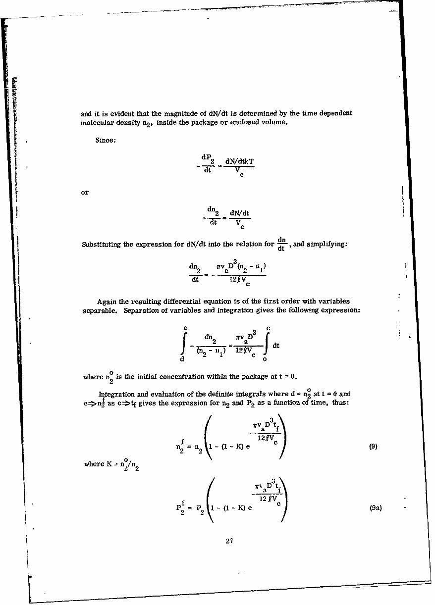
and it is evident that the magnitude of dN/dt is determined by the time dependent
molecular density n2 , inside the package or enclosed volume.
Since:
2 dN/dtkT
ord
dn2 dN/dtdt V
c
d2_
Substituting the expression for dN/dt into the relation for and simplifying.
dw. ITv D(n- n2 a 2 1
dt 12SV
Again the resulting differential equation is of the first order with variablesseparable. Separation of variables and integration gives the following expression:
e cJ dn 2 Irv DV atf 'n2 - Ht 1 2V
d o2 1 0
where n2 is the initial concentration within the package at t 0.
Integration and evaluation of the definite integrals where d = n0 at t = 0 and
e nas e tf gives the expression for n2 and P2 as a function of time, thus:
TV a D 3tf
f 12fV c
where K -- n 0((~~ nn/ 2
a f
2 12V )V
P9- P2 -(1-K)e (9a)
27

IThe free molecular flow rate equation time dependence is obtained by direct sub-
stitution of the above expressions for n2 and P2 into the equations for dN/dt and dV/dt,thus
F t~v aD tf.v 3 I a2 Vc
&! Lov n2 (1 - K)e (9b)
i v lRVD3tf
1V Vva- (1 - K)e12g
ar L c tITVii'v 12V
.I l(1- K)e C
here dV/dt is measured at pressure P = P2
The time dependent gas flow equations, based on the restricting enclosed volumeat the appropriate tube end, that is, the integrated circuit flat package, allows thedetermination of the initial magnitudes of dN/dt and dV/dt and their time rate of change,and the internal package pressure as a function of time under specified test and packageparamelers. In particular, the helium bomb pressure and time duration required todetect and accurately measure a defined leak rate range with corresponding equivalenthole diameters can be estimated. In addition, the decrease in the helium partial pres-sure within the packaee due to viscous outflow during the transfer of the packagefrom the pressure chamber to the bell jar can be ,stimated. This information is re-quired since the helium pressure loss within the package during the transfer sets anupper time limit on the time interval between the termination of the pressure bomb cycleand the actual lcak rate measurement. It should be noted again that the gas floweq'iations must include the time dependence corrections due to the boundary conditionsimposed on the gas flow during the actual package leak rate measurement technique.
It is clear that, (1) setting t = 0 in both the inflow equations for gas flow rate(d',/dt, dV/dt) and internal package pressure P2 gives the initial magnitude of dN/dt,dV/dt, and P2 during the helium pressure bomb test procedure, and (2) setting t = 0in both the outflow equations for gas flow rate (dN/dt, dV/dt) and internal packagepressure P2 gives the initiai magnitude of dN/dt, dV/dt, and P2 during the leak ratemeasurement test procedure.
The tine-corre-ted inflow rate equations must be used when the package leak rateis large, as the leak rate magnitude is directly dependent on the effective leak hole
28

diamieter and length. In this case the differential pressure is significantly reduced, dueto the increase in the internal package pressure, when subjecting the package to heliumpressure bomb fo- at specified time interval. Similarly, for high package leak ratesagain implying relatively large equivalent hole diameters, the time corrected outflowgas flow equations must be used when the molecular density or internal package pres-sure significantly decreases during the time duration required for transfer and package
I1~ leak rate measurement using the helium leak detector system.
n| 29

I
SECTION V11
HELIUM LEAK TEST ANALYSIS AND DETERMINATION OF EQUIVALENTHOLE DIAMETER BASED ON THE MEASURED INTEGRATED CIRCUIT
PACKAGE LEAK RATE WITH HELIUM BOMB PRESSURE ANDTIME SPECIFIED
1. PHYSICAL PROPERTIES OF THE FLAT PACK INTEGRATED CIRCUIT PACKAGEREQUIRED FOR THE THEORETICAL HELIUM LEAK TEST ANALYSIS
The three essential properties required for hermeticity test analysis of the flatpackage used for packaging the integrated circuit (SN347-Dual Low-Level Nand Gate)test vehicle used under project DE-65-10 are (1) the internal volume of the package,(2) the average length of the glass-to-metal seals and, (3) the internal package pres-sure and ambient. The above stated required package properties are:
(1) Internal volume( 1 3) - 10-2 cc.
(2) Average glass-to-metal seal length ---- -0.015" or 0.038 cm.
(3) Internal ambient and pressure(13)------ Air at-1.0 atm.
In general, the internal volume of the package will vary depending on the physicaldimensions of the die and the amount of material used for die attach. Excess glasson the inside of the package at the glass to metal seals will also decrease the internalvolume. In addition, there are internal volume differences depending on the TO num-ber of the package used. The glass to metal seal length will vary slightly due to ex-cess glass surrounding the leads. The internal package pressure is nominally oneatmosphere( 13 ) (generally < 1.0 atm. since the package is sealed using elevatedtemperatures which, when returned to ambient room temperature, creates a smallpartial vacuum within the package). The internal ambient or gas composition willdepend on the circuit manufacturer. (13)
2. ANALYSIS OF THE STEADY STATE VISCOUS, DIFFUSIONAL, AND FREE-MOLECULAR GAS FLOW RATES
In general, the type of gas flow existing in a circular tube will be determined bythe tube dimensions such as the length !Z, which will determine whether end correctionsfor turbulent flow must be considered, and the tube diameter D. If the tube length islong compared to the diameter D, entrance and exit conditions can be neglected and the
30

type of gas flow existing within the tube over the majority of the tube length will thenbe determined by the ratio D/L. Thus, for any tube diameter D, it is evident that themagnitude of the molecular mean free path L, which is a function of the absolute pres-sure at any point along the tube length, will determie the nature of the gas flow. Thetransition from pure viscous flow (high pressure) to a combination of both viscous anddiffusional flow (intermediate pressure) and, finally, to pure free-molecular flow (lowpressures) at a fixed tube diameter has generally been described in the literature bythe viscous flow laws for the high pressure range, viscous flow corrected for slip atthe tube walls for the intermediate pressure range, and the free-molecular flow lawsfor the low pressure range. Figure 4 shows the average velocity of helium and air at250C and( 12 ) the molecular mean free .. h L as a function of the absolute pressure.
As previously stated, the package manufacturer conducts hermeticity tests on thefabricated integrated circuit package prior to lid and die attachment to determine thequality of the glass to metal seals. One technique using the helium leak detector sys-tem consists of sealing one side of the package (vacuum seal) to the helium leak de-tector and subjecting the other package side to helium gas under one atmospherepressure. Since the appropriate package sides are under a constant vacuum pressureand a constant one atmosphere helium gas pressure, and there is no limiting packagevolume, steady state helium gas flow (in this test it is assumed that the free-moleculargas flow law applies) will exist through any defective seal point in the package. Themolecular gas flow rate is then independent of time. The package leak rate is thenmeasured using the helium leak detector which is calibrated using a standard leak suchas the SC-4. For this type of package leak test, the helium gas flow rates as a functionof test parameters and package average glass-to-metal seal length and hole diameterare of importance.
In addition, when subjecting the sealed integrated circuit package to the heliumpressure bomb test procedure, if the package volume is relatively large and/or theequivalent leak hole diameter is small, approximate steady state helium gas flow (inthis case the viscous or diffusional gas flow laws apply) will also exist through anydefective seal point in the package for a time interval determined by the packagevolume, helium bomb pressure, hole diameter, etc.
The graphs in Figures 5 and 6 show the steady state molecular dN/dt and volumedV/dt gas flow rates for viscous and diffusional flow respectively as a function of testand package parameters. In Figure 5 the viscous flow rates are shown as a function ofseveral nominal helium bomb pressures with assumed tube diameters. The constantpressure of one atmosphere on the opposite tube end and the tube length were selectedto simulate the normal internal package pressure and the average glass to metal seallength. In Figure 6 the diffusional flow rates are shown as a function of several heliumbomb pressures and an internal package pressure of one atmosphere with assumed tubediameters. Here, again, the pressures and tube lengths were selected to simulateinternal package pressures, nominal helium bomb pressures, and the average glass-to-metal seal length used in Figure 5. Figure 7 gives the magnitudes of dN/dt and dV/dt
31

A--r . -r r - --
IF
0 Lis p. . 7..........................................................
00 o
L *- .* r. . c
I.. (U -II . .j~I tox I U
.10p~ ~ ~ i 0 I.I U~
E ad
-4
10 b
SH33WILN3 011 H~d 381 NV.b Vn31V
32 .. a
i. c
wOr OD.~ *
0 in
a B. .>
Zte . ?
.~I~zo.w,~JnI- *
100~ 0z w
~oa~o.........I4-4
7:o
S CISOr.~
2a 2 1
' S OP)3 N PA 1VA Alj 3n0 9UA
.w 33

I
II
141 ~* .4100 + 'o fr'*I L%4 CIS
lis U,2
I; a .2 - i
.7I72 r 4-4
___ m -4.
- ~ w- - N - ~ .j3U.-* 0 ~I
-All~U h +0~
Id O)IL~ O4)F U2,ci
0' : I.* IL-..
2~ 2 22
'3S/: /3 N6I/P3Y OA vnO 9U
34U

4 60
0.0
2 -y
LPH- ILP toV coi
35 ,- o

ii
for helium free-molecular flow in terms of the pressure and concentration differential.The length of the package glass-to-metal seal used in calculating the flow rates isconsistent with that value used for determining the viscous and diffusional gas flowrates. Note that for free-molecular flow at these pressures the tube diameter mustbe considerably smaller than that for viscous or diffusional flow. At one atmospherethe tabe diameter required for free-molecular flow must be less than 10-5 cm. It isdifficult to conceive a tube of constant diameter through a seal with these dimensions.Further, it has been shown by Davis, Levenson, and Milleron( 1 6) that at low pres-sures, the tube conductance and gas flow rate under free-molecular flow conditions isdependent on the wall surfate roughness and, in fact, decreases as the degree of sur-face roughness increases. As previously stated, in an actual non-herm.tic IC package,smooth and continuous leak paths are improbable (e.g., separation of the glass toKovar lead seal will result in a leakage path bounded on one side by the rough metal).
Inspection of the free-molecular flow rate dN/dt restrictions when n2 = 0, as isthe case when the outlet end of the tube is at high vacuum, and n1 - 1019 molecules/cc, the approximate molecular density of the internal package gas at one atmosphere,indicates tht at the calculated density gradient dn/dxi1019 mol,.cules/cc/0. 038 cm
2.6 x 10⁷ molecules/cm 4 ,the restricting condition of small density gradients isviolated. In addition, if P 2 = 0 in the volume flow rate equation, the magnitude of
I dV/dt is totally independent of the pressure P1 within "ho rnekage. Based on thepreceding statements, the validity of using this equation in des. ribing the helium gasflow out of the package under vacuum conditions with a high internal package pressureis questionable. It appears that a number of conditions could possibly exist dependingon the equivalent leak hole diameter and geometry including, (1) a gradual transitionfrom viscous to diffusional gas flow or a combination of both types could exist untilthe pressure in the package reaches such a value that all restricting conditions forfree-molecular flow are satisfied; (2) a transition from viscous or diffusional flow tofree-molecular flow at some point within the tube length could occur depending on thehole diameter and the pumping speed of the vacuum system; or (3) the entire tubelength could be under high-vacuum conditions.
The preceding discussion points out the difficulty in describing the type of gas flowwithin a package leak hole or tube during the helium pressure bomb and leak ratemeasurement test procedures.
The curves of dN/dt and dV/dt shown in Figure 7 assume that the free-molecularflow laws for outflow of helium gas from the package are valid for the helium leak testmeasurement when the magnitude of the absolute pressure is sufficiently reduced suchthat the tube orequivalent hole diameter is small compared to the molecular mean freepath and the conditions that D < L and small density gradients exist are satisfied.
The pressure at which cue volume flow rates were calculated is the average pres-sure within the tube, (P1 + P 2)/2, thus average volume flow rates are plotted. The
36

~volume flow rate at any plane within the tube at pressure Px, where Pl >! Px >:P,
cnm be determined by multiplying the average volume flow rate by the ratio Pavg/Px.The volume flow rates can also be referenced to standard temperature and pressureby setting Px = Pstp.
It should be noted here that the steady state magnitude of dN/dt and dV/dt as shownin F'gures 5, 6, and 7, where the specified test and package parameters were selectedto represent actual leak test parameters and package properties, gives the initial(t = 0) magnitudes of dN/dt and dV/dt under identical conditions. Here the values ofthe package pressure and internal volume, hole diameter, etc., require the use of thetime corrected gas flow rate equations. Therefore, the gas flow rate equations fromwhich the curves of Figures 5, 6, and 7 were plotted give the magnitudes of dN/dt anddV/dt that are valid for steady state gas flow. These equations and correspondingcurves hold where there is no restricting enclosed volume on the system and give onlythe initial magnitudes of dN/dt and dV/dt when the gas flows through a hole or tubeinto or out of an enclosed volume, such as the integrated circuit flat package.
Recently, Lund and Berman(15) have developed an equation describing the flow ofgases in capillaries of various length-to-radius ratios over the pressure range ex-tending from the free-molecular to viscous gas flow. The flow of gas through a tubeunder a pressure gradient is expressed as the sum of two terms, namely: (1) a dif-fusive component which decreases with increasing pressure, and (2) a drift componentwhich increases with increasing pressure. The developed gas flow r.te equation givesthe same results as those obtained using the classical flow rate equations summarizedin Section V of this report, within the limited pressure range over which each flow lawis valid in describing the helium gas flow. The magnitudes of dN/dt and dV/dt calcu-lated and plotted in Figures 5, 6, and 7 remarkably agree with the values calculatedusing the general equation of Lund and Berman.
3. ANALYSIS OF THE TIME-DEPENDENT VISCOUS, DIFFUSIONAL, AND FREE-MOLECULAR GAS FLOW RATES
The time-dependent gas flow rate equations as derived in Section VI where anenclosed volume (IC package) imposed a defined boundary condition on the system willbe discussed separately following the testing sequence.
Inspection of the viscous and diffusional gas flow equations describing inflowduring the helium bomb pressure test procedure shows that-
the internal package pressure increases from its initial value of one atmosphereair pressure at t=O to the helium bomb pressure as t-,+ where the magnitudeof Ve, 1), f, and P1 determine the bomb time required to reach pressureequalization.
37

* the molecular dN/dt and volume dV/dt flow rates decrease from their intitialmagnitudes at t=O to zero as t-*- where again the time at which pressureequalization or the flow rate approaches zero is determined by the test andpackage parameters stated above.
Considering next viscous or diffusional outflow from the package when the packageis maintained at one atmosphere external pressure, i.e., during the transfer of thepackage from the bomb chamber to the bell jar:
s the internal package pressure decreases from its initial value after the heliumpressure bomb test procedure at t=O to a pressure determined by the transfertime. The final pressure if the package is maintained at one atmosphere ex-ternal pressure obviously would be one atmosphere or pressure equilibrium.
j. the molecular and volume flow rates, dN/dt and dV/dt, decrease from theirinitial magnitude at t=O to a flow rate again determined by the transfer time.The flow rates go to zero if pressure equalization is attained.
. The time interval required to reach approximate pressure equilibrium, aspecific internal package pressure, or gas flow rate is determined by thetest and package parameters previously discussed. In addition, the gascomposition and flow rates at outflow conditions will be proportional to theinternal package partial pressures of helium gas and air.
Finally, considering free-molecular gas outflow from the package where the ex-ternal package is subjected to high vacuum conditions as is the case during the leakrate test procedure:
* Viscous or diffusional gas flow may exist for a given time interval until theabsolute pressure within the package and leak hole is reduced to such a mag-nitude that for a given hole diameter D, D< L holds, and free-molecular gasflow exists within the tube or hole. During viscous or diffusional flow theinternal package pressure and gas flow rates decrease from their initialmagnitudes after helium pressure bomb and package transfer at t=O with timeuntil free-molecular flow exists. The times required to reach a specificpackage pressure is determined by the test and package parameters.
0 Under the conditions of free-molecular flow i.e. when the absolute pressureis such that D<L, the internal package pressure and gas flow rates will con-tinue to decrease with time until pressure equilibrium is attained. The finalpackage pressure is determined by the ultimate pressure of the vacuumsystem.
-8
* During both viscous or diffusional and free-molecular gas outflow from thepackage, the outflowing gas will contain both helium and air, where the gasflow rates are approximately proportional to the partial pressure of the gaswithin the package. The approximation is required here since the free-molecular gas flow rate is directly proportional to the average molecularvelocity, and from Figure 4, it is seen that the ratio of the average velocityof helium to air is approximately 2.50.
In order to evaluate the effectiveness of the helium leak test system as a relia-bility screen test, it is necessary to determine the range of molecular or volume leakrates, which are dependent on the package and test parameters as well as the equiva-lent tube or hole diameter, that are within the detection sensitivity of the system.
Figure 8 shows the results of computer computations indicating the time requiredfor the internal package pressure to attain any specific value and the approximatetime for pressure equalization as a function of tube diameter when the integrated cir-cuit package is subjected to a helium bomb pressure of 45 psig. It is apparent thatfor tube diameters greater than 5 microns, pressure equalization is attained in lessthan ten minutes, and since the inflow and outflow rates are approximately equal,most of the helium forced into the package during pressure bombing willP leak outduring the transfer of the package to the bell jar and the pumpdown cycle of the vac-uum system prior to the leak rate measurement. For this case, depending on thehole diameter, the measured package leak rate will be orders of magnitude less thanthe true leak rate and thus could be mistaken for a hermetic package. It is evidentthat a gross leak test, such as one of the types described in Section III, must beconducted in conjunction with the fine leak test to insure package hermeticity. Cur-rently, there is no single leak test capable of detecting both gross package leaks,i.e., dV/dt >10- 5 std. cc/ie/sec., and fine package leaks, i.e., 10- 9 <dV/dt<10- 5 std.cc/lIe/sec.
Further, at a tube diameter of 0.5 microns, the bomb time required tr attain aninternal helium partial pressure of one atmosphere is approximately 100 hours. Thispressure bomb time is excessive, from the manufacture, 's viewpoint, when the userspecifies a helium leak screen test on thousands of individual units. Thus the standardbomb time used by the semiconductor industry is generally four (4) hours at a bombpressure of 45 psig and represents a tradeoff between detection sensitivity and testingtime. Therefore, under these specified test conditions, the helium leak test isoptimized to detect and measure with reasonable accuracy the necessary range ofpackage leak rates. The current maximum integrated circuit package leak rate spe-ciecation is dV/dt < 5 x 10⁻⁷ std.cc/Hie/sec. In addition, measured leak rates< 10- 9
std.cc/fic/sec. may be attributed entirely to the outgassing of adsorbed helium on thee:-ternal package surfaces. The nitrogen gas flush test procedure reduces this ad-sorbed helium; however, the presence of greases or film-, on the package could resultin significant outgassing of adsorbed helium which points out the necessity for a clean
39

P2 INDNE/44
i0
IC
AA
II
C: 0
P2 1WCYESC
o 6 o
4 U
* 0
CC
2 -4-
o .o
0 2
40i

I external package surface. It is readily apparent that the package leak rate range overwhich Qhe helium leak test system is most sensitive lies in the 10- 9 - 10- 6 std. cc/He/sec range which corresponds to equivalent hole diameters in the range from 0.5-5.0microns. Secondly, the greater the ratio of the partial pressure of helium to air withinthe package, the more accurate the measured package leak rate becomes. This is dueto the fact that the helium leak detector system detects only helium gas flowing out of thepackage, and since the leak rate is defined by the equivalent hole diameter the true leakrate is the summation of the leak rate of helium and air.
Since package hermeticity is an essential requirement for assuring the reli-ability of integrated circuits and there is no single hermetic seal test capable ofdetecting and measuring package leak rates over the required range (dV/dt 2 10- 9 cc/see.), both a fine and a gross leak test, in that order, must be conducted to assurepackage hermeticity. The test order is important when gross leak tests using liquidtracer fluids are employed since minute particle contaminants within the liquid canseal existing leakage paths prior to fine leak testing. However, even when both fineand gross leak tests are performed, a nonhermetic package can escape detection. Inthe case of a gross leaker where the volume leak rate is equal to or greater than 10- 4
std. cc/sec., the defective seal point or hole can be temporarily sealed by particlesor contaminants in the test solution pprticular to the type of gross leak test utilized.In addition, there exists the volume leak rate range from approximately 10- 6 to 10- 4
std. cc/sec., where both the fine leak tests, including the Helium and Radiflo test, andthe gross leak tests are relatively insensitive. Within the above leak rate rang3, theequivalent hole diameters are relatively large and, when using either of the standardfine leak test systems, most of the tracer fluid forced into the package during thepressure bomb test procedure flows .-ut of the package before the leak rate measure-ment is performed, resulting in a measured leak rate orders of magnitude lower thanthe actual leak ratc. Further, the detection sensitivity of the standard gross leak teitsfor leak rates less than 10- 4 std. cc/sec., is a matter of speculation.
The measurement of package hermet-city utilizing the described standard fineand gross leak tests is based purely on the detection of a tracer fluid which is forcedinto the package and the subsequent detection of the fluid within or penetrating thepackage. It is readily apparent that these types of hermeticit, tests measure packageintegrity with no direct correlation between circuit reliability and package leak rate.A measured package leak rate exceeding the maximum specified value may be thesummation of the leak rates of a large number of small holes (defective seal points),or a single large hole. In the former case, the average hole diameter can be smallenough such that no appreciable amount of water vapor or moisture can penetrate thedefective seals. In the latter case, the diameter of the singular hole can be largeenough to allow the penetration of a sufficient amount 5f moisture to cause circuit para-meter degradation. Thus, the concept of a maximum acceptable leak hoIe di.,meter,.ccification has inherently more physical meaning when relating package hermeticity
to integrated circuit reliability.
41
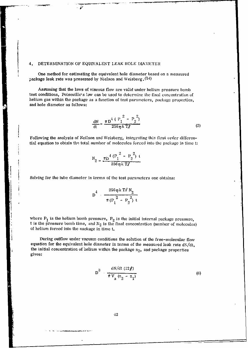
t 4. DETERMINATION OF EQUIVALENT LEAK HOLE DIAMXTEHIT
One method for estimating the equivalent hole diameter based on a measuredpackage leak rate was presented by Nielson and Weisberg. (1 4 )
Assuming that the laws of viscous flow are valid under helium pressure bombtest conditions, Poiseuille's low can be used to determine the final concentration ofhelium gas within the package as a function of test parameters, package properties,and hole diameter as follows:
2 2
dN IT rD 4 ( -1 9)
dt 2567kT (2)
Following the analysis of Neilson and Weisberg, integrating this first order differen-tial equation to obtain the total number of molecules forced into the package in time t:
N2 7T) (P - P)t256 7k TP
Solving for the tube diameter in terms of the test parameters one obtains:
4 2567k TF N9
D - 2 2lr(P -P2) t
where P1 is the helium bomb pressure, P2 is the initial internal package pressure,t is the pressure bomb time, and N2 is the final concentration (number of molecules)of helium forced into the nackage in time t.
During outflow under vacuum conditions the solution of the free-molecular flowequation for the equivalent hole diameter in terms of the measured leak rate dN/dt,the initial concentration of helium within the package n2, and package propertiesgives:
D dN/dt (12,P)
I V a(n 2 - n1 )
42

5F
j Since N2 = (n2 - nl) x Volume of the package, the two expressions for the tube diam-
eter can bc combined and solved for the equivalent leak hole diameter which resultsin the following relation:
/7(14)
,3072 7 k T, 2 V (dN/dt)D = [2 t (10)17t v (P12 2)t
This equation is obviously valid only for small package leak rates since it assumes
that during helium pressure bomb and leak rate measurement test procedures themagnitudes of dN/dt and P 2 (n2 ) at both inflow and outflow conditions are independentof time. In addition, this final equation for estimating the equivalent hole diameterbased on a measured package leak rate assumes that, since N2 was considered equalto (n2 - n,) x Package Volume, the free-molecular gas flow law is valid for determin-ing the rate of outflow of helium gas at relatively high pressures (104 - 107 dynes/cm 2 or 0. 01 - 10 atmospheres) which may introduce a significant error as discussedin Section VII-2. With reference to the curves of Figure 4, it is apparent that forthe nominal tube diameters ranging from 0. 10 to 10 microns, free-molecular flow will
exist when the pressure is approximately equal to or less than 104 dynes/cm 2 . Depend-ing on the tube diameter and pumping speed of the vacuum system, it-is conceivablethat the pressure within the package could decrease to an absolute pressure of 104
dynes/cm 2 (luring the pumpdown cycle. To determine the error in the calculated valueof D when the leak rate measurement is made at a time when the package pres,'-rediffers significantly from the pressure after the helium pressure bomb, assume a con-dition where the internal package pressure after helium pressure bomb is 107 dynes/cm 2 . It is clear that if the package leak rate dN/dt is measured at time tm when theinternal package pressure is near 10 4 dynes/cm2 , the ratio
N22 (concentration after helium pressure bomb)
2 c =10 3 where n- 0nt Nt
(concentration at time of dN/dt measurement)c
and it follows that: N2 = 103 i t x Volume
Solving for the diameter D using this equality between the inflow and outflow equa-tions results in increasing the radicand by the factor of 103. Thus, the calculatedvalue of 1) assuming (n9 - n1 ) N9/V will be smaller than the actual value by a factor of
43

----- --- -T--
The more correct value of D will then be D calculated multiplied by ormore generally:
D D x (pactual calculated x Pm (pressure at dN/dt measurement) (11)
Comparison of the calculated values of D from both the original and the modifiedexpression, giving the more accurate value for D using standard test parameters andpackage properties, indicates that the equation given by Neilson and Weisberg(1 4 ) givesorder of magnitude approximations for the equivalent hole diameter over a limited rangeof diameters. The accuracy of the calculated value of D, when the pressure at whichthe package leak rate is measured is unknown, is greatest at the small hole diamet "rs,and significant error is introduced when the hole diameter exceeds 5 microns forreasons explained previously.
Another consideration is the fact that the viscous inflow laws are only approxi-mately valid if the equivalent leak h-le is the effective summation of several smallerdiameter holes. Further, both the inflow and outflow of helium gas from the pack-age can result from the diffusion of the helium through the glass seals or ceramicmaterial depending on the type of package. If this condition exists, the equationsused for estimating the equivalent leak hole diameter will not accurately describethe type of gas flow existing under test conditions.
,I
I.
44

SECTION VIII
I-
CONCLUSIONS AND RECOMMENDATIONS
The review and analysis of the classical steady flow rate equations pointed out theimportant flow characteristics and the restricting conditions under which steady stateviscous, diffusional, and free-molecular gas flow can exist in a cylindrical tube. Thesebasic equations were then expanded Eo include the necessary time dependence correc-tions required when an enclosed volume, i.e., the integrated circuit package, is im-posed on the system.
The steady state molecular and volume flow rate versus tube diameter curvesshown in Figures 5-7 allow a rapid determination of dN/dt and dV/dt magnitudes forthe basic types of helium gas flow through cylindrical tubes over a range of tube dia-meters and inlet and outlet pressures. The pressure magnitudes were selected tosimulate typical internal and external package pressures consistent with the heliumleak test system. The tube length used was the average glass-to-metal seal lengthof several integrated circuit metal flat packages. These curves are consistent withthe results obtained using the Lund-Berman general gas flow rate equation.
Analysis of the helium leak test system using the time corrected flow equationshows that the volume leak rate range over which the helium system has the greatestdetection sensitivity is from 10- 9 to 10-6 std. cc/He/sec. In addition, the detectionsensitivity of the standard gross leak tests decreases significantly for package leakrates less than 10- 4 std. cc/sec. Therefore, it is evident that hermeticity testing ofintegrated circuit packages must include both a fine and a gross leak test. However,non-hermetic packages can still escape detection due to the lack of overlap betweenthe fine and gross leak tests. Both tests are relatively insensitive for detecting non-hermetic packages with volume leak rates in the 10-6 to 10- 4 std. cc/sec. range.Therefore a single hermeticity screen test capable of detecting and accurately meas-uring the total volume leak rate range of dV/dt >_ 10- 9 std. cc/sec. is required.
The time dependent flow rate equations developed in this report can be used toestimate gas flow rates and internal package pressures as a function of time underdefined hermeticity test parameters and actual package properties. Secondly, thehelium bomb time and pressure required to optimize the helium leak test sensitivityover a desired volume leak rate range can be determined. At a helium bomb pressureof 45 psig, the hole diameter required for a volume leak rate of 5 x 10- 7 std. cc/He/sec.,the standard maximum IC package leak rate specification, is approximately 0. 85.u(microns). A specified minimum helium partial pressure within the package of one
45
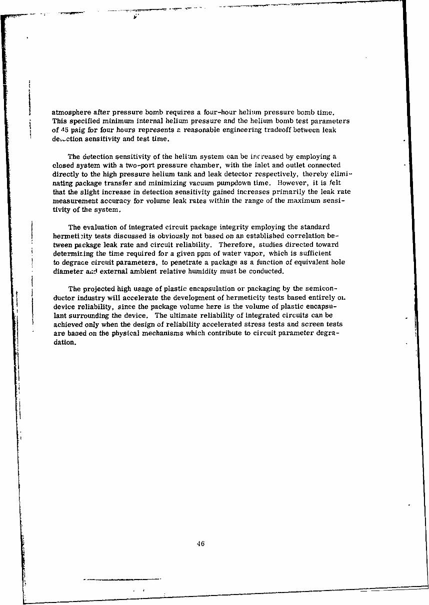
i atmosphere after pressure bomb requires a four-hour helium pressure bomb time.This specified minimum internal helium pressure and the helium bomb test parametersof 45 psig for four hours represents P reasonable engineering tradeoff between leakde,.ction sensitivity and test time.
The detection sensitivity of the helium system can be increased by employing aclosed system with a two-port pressure chamber, with the inlet and outlet connecteddirectly to the high pressure helium tank and leak detector respectively, thereby elimi-nating package transfer and minimizing vacuum pumpdown time. However, it is feltthat the slight increase in detection sensitivity gained increases primarily the leak ratemeasurement accuracy for volume leak rates within the range of the maximum sensi-tivity of the system.
The evaluation of integrated circuit package integrity employing the standardhermetibity tests discussed is obviously not based on an established correlation be-tween package leak rate and circuit reliability. Therefore, studies directed towarddetermiting the time required for a given ppm of water vapor, which is sufficientto degrace circuit parameters, to penetrate a package as a function of equivalent holediameter aid external ambient relative humidity must be conducted.
The projected high usage of plastic encapsulation or packaging by the semicon-ductor industry will accelerate the development of hermeticity tests based entirely ol.device reliability, since the package volume here is the volume of plastic encapsu-Snt surrounding the device. The ultimate reliability of integrated circuits can beachieved only when the design of reliability accelerated stress tests and screen tests
are based on the physical mechanisms which contribute to circuit parameter degra-dation.
46
___________________________________

APPENDIX
DERIVATION OF THE CLASSICAL EQUATIONS DESCRIBING FLUIDFLOW THROUGH LONG CYLINDRICAL TUBES APPLICABLE
IN THE DETERMINATION OF INTEGRATED CIRCUITPACKAGE LEAK RATES
1. POISEUILLE'S JAWS OF VISCOUS FLUID FLOW FOR LIQUIDS AND GASES
When an incompressible fluid, e.g., a liquid, flows under steady state conditionsthrough a closed tube, both the mass and the volume passing any given point within thetube per unit time are constant. However, with a compressible fluid, e.g., a gas,the mass per unit time is still constant (continuity of mass flow under steady stateconditions requires that no accumulation or diminution of fluid occurs), but the effects 4
of pressure and temperature on the volume cause a variation in the volume flow rateat points within the tube. The derivations used here for viscous flow rates of bothincompressible and compressible fluids follow that given by Kennard. (17) In the fol-lowing fluid flow derivations the high pressure tube end and the low pressure tube endwill be designated PI and P2 respectively.
Consider a liquid flowing in a cylindrical tube of length) and radius a due to apressure differential Ap between the inlet and outlet end of the tube as shown in FigureA-1. It will be assumed that the flow is steady and everywhere parallel to the axis of
the tube, p is a function of x only, v is a function of r only, and that the liquid in con-tact with the tube wall has zero velocity (i. e., no slip occurs). The preceding condi-tions imply laminar flow of the liquid. Since the fluid is incompressible, the pressureis uniformly distriouted t'iroughout the length of the tube.2, and the pressure gradientdp/deis constant.
Further, consider a fluid inside an inner cylinder within the cylindrical tube withlength dx and radius r.
For a steady flow of fluid due to the pressure differential to exist in the axialdirection, the net force due to the pressure differential at opposite ends of the elementallength dx must equal the viscous force or drag exerted by adjacent fluid cylinders oneach other. Thus, the following condition must be met for steady flow to exist:
EF (due to pressure differential) = Fv (due to viscous drag) (A-1)xV
Since pressure equals force per unit area,
F PIA - P2A = AAP (A-1a)
47

u 1 Fr D
ta
iPI[1
[ ______________
hi

I'
The viscous or frictional force Fv, resisting the relative motion of any two adja-
cent fluid layers, is proportional to S, the area of the interface, and to dv/dr, thevelocity gradient between th.m. This is illustrated in Figure A-2. Expressed mathe-* matically:
F=-Sdv or F dv (A-lb)
v -E o Fd -
where dv/dr is negative and the constant of proportionality
AI
% L
Figure A-2. Diagram Illustrating the Frictional Force Resisting the RelativeMotion of Two Adjacent Layers of a Viscous Fluid
49

II
where ?is the coefficient of viscosity and is characteristic of the fluid.
Then, equating forces:
2 d
irr dp = -77 21Tr dx dvdr (A-2)dpr
Since-- is constant over the tube length.dx
dp= -(Pl (A-2a)
Rewriting equation A-2:
(Pf - p2 )-dv = - 2 rdr (A-2b)
Integrating, assuming no slip at the tube wall such that at r = a, v = o
-J dv 2 77,f rdr
x - P2) 2 2V 4--,C (a2 - r (A-3)
Tc jbtain the total volume V or liquid flow through the tube per unit time:
dV ( a
dt vdA = v2ffrdr (A-4)
50

Substituting the expression for v:
a
dV (/I - P2) f 2 2dt -2f--"-- 4- - (a" - r) rdr
0
ad (P I - P2 ) 2
d -tV 2a=r -r 3 ) dr (A-4a)' '- -'-- (ar-r"dr
o
Integraion of the above expression yields:
2 1T (p -p)___ [dV_ _ 1 2 a rdt 4 7!, 2 4
4dV 1 tadt 8771 (p1 P2 (A-5)
Thus, assuming no slip at the tube wall, equation A-5 represents Poiseuille'sequation for the volume flow rate of an incompressible fluid where the volume flow rateis constant throughout the tube length.
Consider now the flow of a compressible fluid, a gas, where the pressure gradientdp along the tube is not a constant. Using equation (A-2):dx
0 dv
irT rdp = -772lTrdx L (A-2)
Again assu-ning no slip at the tube wall such that at v = o, r a, rearranging andintegrating:
o a
dv = rdr
V rI 5 1
i - d
51

The above equation expresses the velocity of gas flow in the tube as a function ofthe pressure gradient at a specific plane and the radial distance r from the tube axis.
Since the mass of the gas flowing through any cross sectional area of the tube perunit time must be a constant, the mass flow rate can be determined as follows:
dV dM {-adt x p (density) =d (A-6a)
2,ff rvdr = to'al volume flowing through a cross sectional area (A-6b)0 of the cylindrical tube
Multiplying the volume flow rate by the density of the fluid at a specific planewithin the tube, we obtain the total mass flow through that plane per unit time:
admdt-= p f 2jrvdr (A-6c)
0
Now, p pM/RT where p is pressure, M is the molecular mass, R is the gascorstant, and T the absolute temperature in an ideal gas.
Thus, the density of the gas at any plane within the tube is a function of the pres-sure at that plane. Note here that for an incompressible fluid the density is not afunction of pressure.
Substituting for p and v and integrating:
radM 2r pM dp (a2 2 rdr (A-6d)dt 47 RT dx (I
0
dM 2nt pM dp ar r
dt 77RT dx 2 40
dM = =a pM dp (A-6e)dt 817 RT dx
52

i'
Integrating over the tube length 2 and the pressure p where p and p are the pres-sures at opposite ends of the cylindrical tube, we can obtain the total mass flow per
unit time at any plane of the tube:
2P2
0 . - 5pdp (A-6
1 P1
dM ir a 4 M 12 P2
dt 8,T \T) 2 1 -2 J
Now the volume flow rate at a cross sectional plane within the tube can be deter-mined by dividing the last equation by the density of the fluid at that plane which, inturn, is a function of the pressure p0 at that plane.
Thus:
dV _dM ira 2 2 (A-6h)dt dt 8772p [2 1 P2
Here, po is the pressure at which the volume flow rate is measured.
Again, where there is no slip at the wall of the tube, the volume flow rate at pres-sure p is expressed by the following:
dV 7ra 4 2 27F 6f77p p -P 2
2) (A-7)
The basic equations for the volume flow rate of an incompressible and a compressiblefluid in terms of the tube diame,, r D, w2reU = a, can be expressed as follows:
dV I D4
d = 128 (P - P2 ) where D > > L (ncompressible Fluid) (A-8)
D4dV _ lj4 ( 2 2)dVp _ P2 where D > > L (Compressible Fluid) (A-9)dt 256fp 0 where
53

I.,
iI
The equation for the volume flow rate of a compressible fluid (i. e., a gas) can beexpressed in terms of the molecular flow rate as follows:
pV =nRTorpoV = nRT
R (gas constant)Now, k (Boltzmann's Constant) N- (Avogadro's Number)
Therefore, R = kN ° andp oV= nRT = (nN ) kT
V (nN0) k T
Po
Rewriting, we have:
dV 7 D4 2 2dt- 256 7Po0 (P 1 P2
wedV d nN') kIT ,D4 2 2 (A10)dt dt Po 2567,1o p 1 2 - p 2 (A-10)2
0 0
i- 4 2 2dN 7T (p 1 - P2 )
dt 2567kT
where N =nN o number of molecules and D > > L.
2. DIFFUSIONAL FLOW LAWS OF A GAS
Consider the molecular flow by diffusion through a circular tube due to a concen-tration gradient, dn/dx. In this case a uniform temperature and pressure throughoutthe tube must be assumed since both a temperature gradient, dT/dx, and a pressure
gradient, dp/dx, will result in gas flow through the tube. It is assumed then that,P 1
= P2, the temperature is uniform, D > L, and a concentration gradient dn/dxexists along the tube.
The fundamental diffusion equation (Fick's first diffusion law) is expressed asfollows:
dN Adn dN dn (18)
54

A A
Figuire A-3. Diagram Used in Deriving the Diffusional Gais Flow Law Through aCylindricald Tube Duc to a Concentration Gradient
55
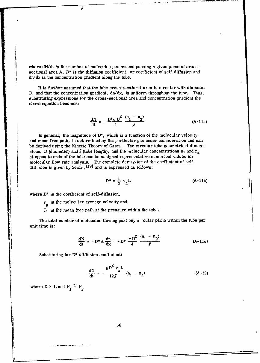
where dN/dt is the number of molecules per second passing a given plane of cross-sectional area A, D* is the diffusion coefficient, or coe.ficient of self-diffusion anddn/dx is the concentration gradient along the tube.
It is further assumed that the tube cross-sectional area is circular with diameterD, and that the concentration gradient, dn/dx, is uniform throughout the tube. Thus,substituting expressions for the cross-sectional area and concentration gradient theabove equation becomes:
d__N - D2 (n1 - n2 ) (A-Ila)dt 4 '
In general, the magnitude of D*, which is a function of the molecular velocityand mean free path, is determined by the particular gas under consideration and canbe derived using the Kinetic Theory of Gase:.. The circular tube geometrical dimen-sions, D (diameter) and l (tube length), and the molecular concentrations n1 and n2
at opposite ends of the tube can be assigned representative numerical values formolecular flow rate analysis. The complete deri- .ion of the coefficient of self-diffusion is given by Sears, (19) and is expressed aE follows:
D* = v L (A-11b)3a .
where D* is the coefficient of sell-diffusion,
va is the molecular average velocity and,
L is the mean free path at the pressure within the tube.
The total number of molecules flowing past any c "cular plarte within the tube perunit time is:
dN dn iD 2 (n1 - n2Ad-- = D* A- n -D* 2 (A-11c)
Substituting for D* (diffusion coefficient)i2
dN aD2 vaL
dt 1- - 12,n (n1 2)
where D > L and P P,
56
- •- - - - -

and d IV D2 Va (P1 P2 (A-12a)dt 121~p
0
where D >L
Since the molecular concentrations n1 and n2 at opposite ends of the tube havedifferent magnitudes, diffusional gas flow can be interpreted as a flow resulting fromthe partial pressure gradient created within the tube.
It should be noted here that if a pressure gradient exists along the tube length,the total molecular flow rate will be the sum of the viscous and the diffusional flowrates. In general, however, the viscous flow rate will exceed the diffusional flowrate only when D > > L. Thus, as D approaches the magnitude of L, the diffusionalflow rate will predominate.
3. FREE-MOLECULAR FLOW LAWS OF A GAS
The preceding molecular flow rate derivation assumed D > L, a :ondition underwhich intermolecular collisions occur. Now, if D <L, the collision of molecules withthe walls of the tube rather than intermolecular collisions will predominate and deter-
mine the molecular flow rate. A uniform temperature throughout the tube must againbe assumed. The appropriate molecular flow rate when D < L is derived by Kennard( 17 )
using the kinetic theory of gases and is given by the following equation:
D3dN 1T Dva (nl - n 2)dt' = 121 (- 3
where:
D<LD<<j
L dnn dx
The following derivation for the free-molecular flow rate of a gas through a cylin-drical tube of diameter D and length 1 differs from that given by Kennard(17 ) in that the
molecular flow rate -- at any point in the cross-sectional area of the circular tube isdtderived. The total flow rate at any plane in the circular tube can then be determined
by integration over the cross-sectional area. Kennard's flow equation is in a moregeneral form, where the cross-sectional area can assume various geometrical shapes.
Figure A-4 shows a circular tube of radius a and length . It is assumed that thetube walls arc perfectly diffusing surfaces, the temperature is uniform, and that a
57

Il
580

constant pressure differential, (P - P ) between the two opposite ends of the tube is
maintained such that a concentration gradient, E exists along the tube length.
Consider ar, elemental area ds, a distance z from the tube axis and lying in thecross-sectional plane designated P. The molecules flowing through ds come from allpoints on the interior wall surfaces and since perfectly diffusing surfaces are assumed,the total number of molecules flowing toward ds from an elemental surface area ds' is
dN = n'Vads'dt ds' cos 6 '2 (A-13a)
where
_ ds cos 9dw- 2
r
From Figure A-4 the following relations are apparent:
2 2 2r =x +s
cosO rrr2 a2 _2 z2 )
Cos, =r +a (x +z2ra (Cosine Law)
s2 =a + z - 2azcosb2 2 2 2
r = x + a +z - 2az cos
ds' = adodx
Substituting for cosO, cose', ds':
n'v dsdt 2 2 2 2dN a (x) (r +a -x -dxdN 2 r 2ra
The concentration n' at any plane p', where the restriction of small concentrationgradients is imposed, can be expressed as:
ni = no +x dn0 dx
59
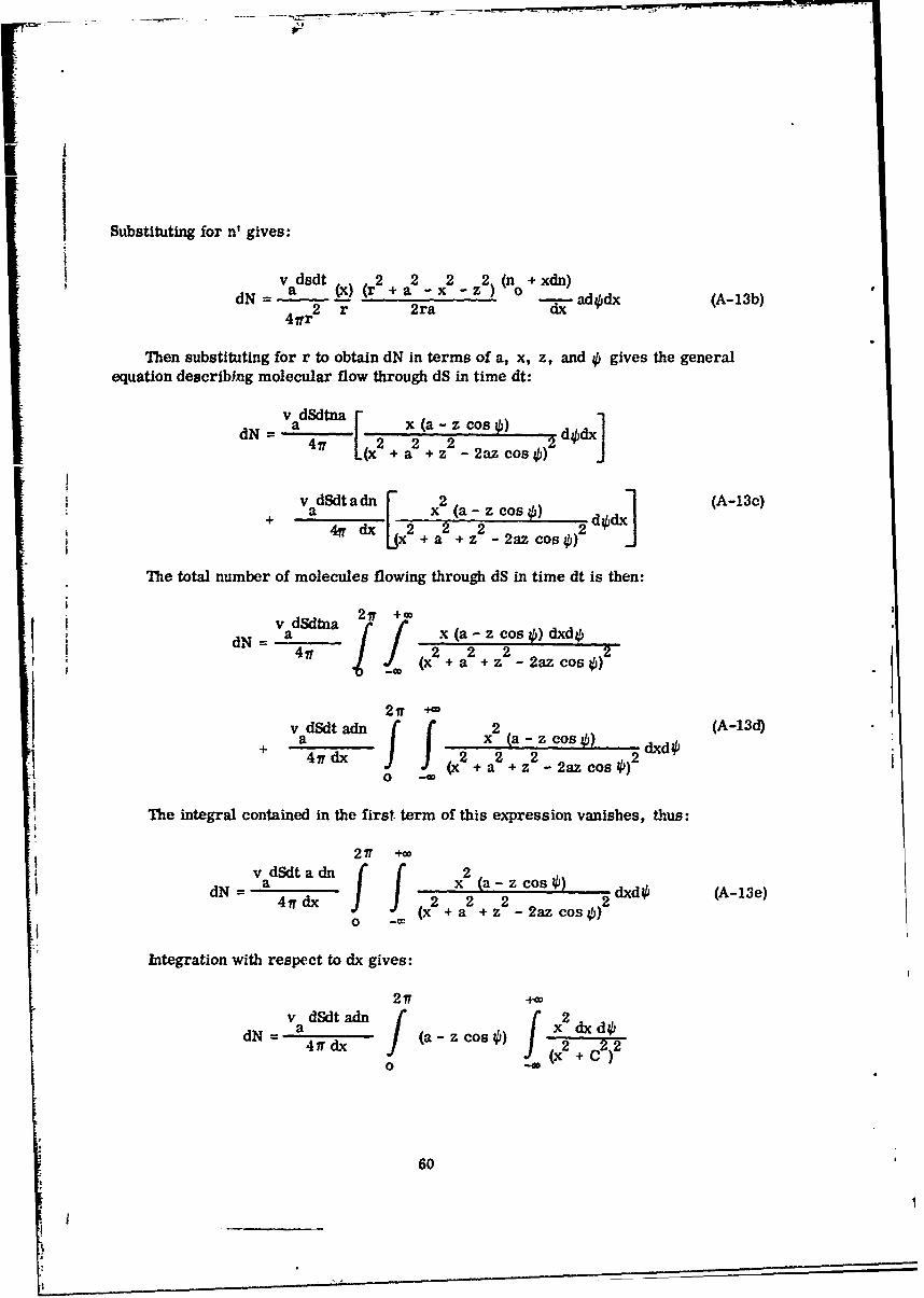
Substituting for n' gives:
v dsdt 2 2 2 2 (n +xdn)dN = va dt(k) (r 2+ a -x -z) o0 dd (A-13b)
4fr2 r 2ra
Then substituting for r to obtain dN in terms of a, x, z, and 4, gives the generalequation describing molecular flow through dS in time dt:
i v dSdtna
VN=a x (a - zcos4' d4'dx]I(x +a +z - 2az cos4'
+ v dSdt a dn [ 2 o. s -l (A-13c)+ a 4g dx 2 x 2 a.--z cos 2 dodx]
The total number of molecules flowing through dS in time dt is then:
v dSdtna 21T +cp
dN = a x(a-zcos 0) dxdOj417 2 2 2 2-I 4(x + a + z - 2az cos )
21T +vadSdt adn x2 (a -z cos ()Ad+ 477 dx 2 22ddf I&(x 2 + a2 + z - 2az cos4)2
0
The integral contained in the first term of this expression vanishes, thus:
217 +w
dN = a x (a- z cos) dxd (A-13e)477dix (x2 2 2) 2dd4(A1e(x +a +z2 -2azcos 2
0 -
Integration with respect to dx gives:
217Tv dSdtadn (af x2dN= af fx xa o b ," dxd)42
O (X +C)
0
_____60
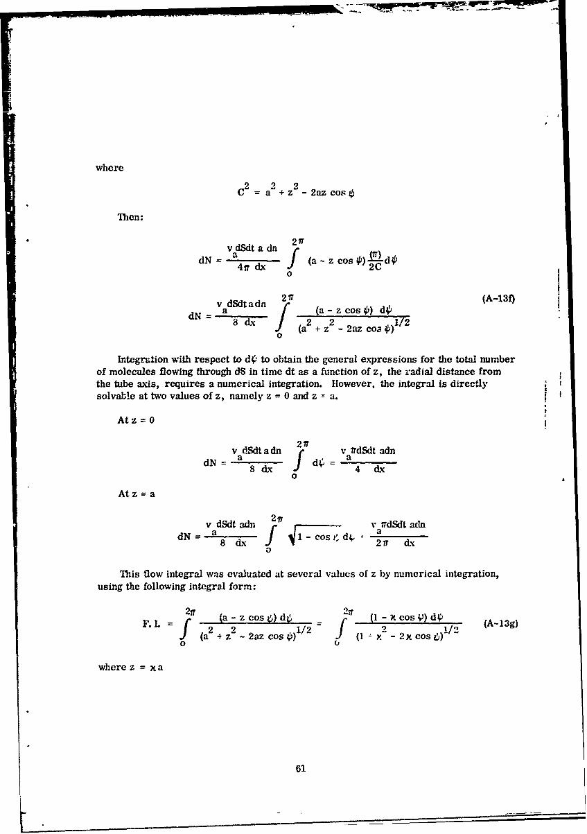
whereC2 2 2C= a +z - 2az cos
Then:
v dSdt a dn 2I
dN = a 4 f (a-zcos )2dO
0
v dSdtadn 2 17 (A-13f)dN = a [ (a-zcos4) d8dx ] 2 21/2
Sdxa2 +z -2azco 0)
Integration with respect to dO to obtain the general expressions for the total numberof molecules flowing through dS in time dt as a function of z, the radial distance fromthe tube axis, requires a numerical integration. However, the integral is directlysolvable at two values of z, namely z = 0 and z = a.
Atz= 0
217v dSdt a dn 2 v IdSdt adnaN =fa d, a
8dx f d4 4 dx0
Atz = a
v dSdt adn 217v idSdt adn
8 dx f 4i-CS1 217 dx0
This flow integral was evaluated at several values of z by numerical integration,using the following integral form:
21r 2 17F.L fazos5d 2 1/2 -/2)d~ (A-13g)
(a2 + z - 2az cos (I 2Y 2x cos0 0
where z = a
61

rhe results of computer calculations is shown in the Figure A-5 and gives the
value of the flow integral from x 0 to x =I corresponding to z 0 and z a
respectively.
X- MM-O CT:2IT55
$0 0. . 05 06 . .8 a? t
Fiur A5 Gap f lo ntgrlVesu
1 4J 62

The expression for dN/dt, through an elemental area dS at a point z, a radialdistance xa from the axis, using the parabolic approximation function then becomes:
dN v aadndS 22. 92 &-+ 0. 64 -+ 6. 28 (A-13h)
L aa
Jntegration over the circular cross-sectional area where dS = zdodz
_N v a ad 2ir a ( . 2+/Nz 2.92 a f+ 0.64 -+ 6.2 dzdO (A-13i)dt 8 dx 2a
2 3dN va (adn) 27T (2.62 a) irv a dndN a a
dt 8 dx 1.525 dx
In terms of the tube diameter D and tube lengthf the flow rate becomes:
dN 1TVa D (nI - n2 ) (A-13)dt 12.2R
where
D<L~D <<.f
L dn- 0 - <<
n dx
I 3dV _ a D (Pl2- y
= 12.2,f P (A-14)0
The equations derived in this section are valid after steady state, flow existswithin the tube. Entrance and exit conditions were considered negligible. The gasflow equations derived, including limiting conditions, are summarized for referencein the following subsection.
These equations are valid when considering small package leak rates where thechange in the internal package pressure during both the inflow (helium pressure bomb)and outflow (leak rate measurement) test procedures can be considered negligible.
63

I4.SUMMARY OF EQUATIONS CHARACTERIZING FLUEI) FLOW THROUGH A
CIRCULAR TUBE INCLUDING DEFINITION OF TERMS
Type of Fluid Flow Equation Equation LimitingReferenced Conditions
Poiseuille's Law for Flow (A-8) D >> L
of an incompressible dV 1D (P 1 - P2 )fluid, i e., a liquid dt 12877.
Poiseuille's Law for Flow 4 2 2 (A-9) D>> L
of a compressible fluid, dV 1D (P - 2 (1)i.e., a gas cit 25677fP0' 0
dN tTD 4 (P1 - P 2 2) (2) (A-10) D>> L
dt 2567.kTf
Diffusional Flow of a rD2 (A-12) 1)> L
f gas due to a concen- dNL a (n1 n2 ) P I P2tration gradient (Large dt 12 2
diameter tube equation)2 (A-12a) D> LdVD 2 Lv -
dV a (PI - ?) (3)
dt 12' P0
Free-molecular Flow of rD3 v (A-13) D< La gas due to a concen- dN a (n 2 (6) D <<
tration gradient or dt = 12X L dn
pressure gradiert (Small n d«
diameter tube equation) 3D < Ldv aD V (P - 2 (5) (A-14) D <<
dt 12 P L dno - 1-<0n d
DEFINITION OF TERMS
dV/dt flow rate through circular tube in terms of volume (cc) of liquid or
gas flowing per unit time
dN/dt gas flow rate through circular tube in terms of the number of mole-
cules flowing per unit time
6.1

D diameter of circular tube in centimeters
- length of circular tube in centimeters
viscosity of fluid in poise (gm/sec. cm)
k = Bohmman's Constant in ergs K -1
T absolute temperature (Degree Kelvin)
L = mean freepaith of molecules in centimeters
va average velocity of molecules in cm/sec.
NO - Avogadro's number (molecules mol - )
D* = Coefficient of self-diffusion (cm 2/sec)
R = Universal gas constant In ergs °K-1 mo]- 1
P0 = Average pressure or piessure at which dV/dt is measuredin dynes/cm
2
pit P = pressures at oppcsite ends of circular tule in dynes/cm 2
nit n concentration of the gas molecules under consideration at opposite2 ends of the tube in terms of the number of molecules per unit
volume (molecules/cc)I2
dP/dx = pressure gradient along tube in terms of force per unit area (dynes/cm )
per unit length.
dn/dx = concentration gradient along tube in terms of molecules per unitvolume (molecules/cc) per unit length.
5. ANALYSIS OF THE CLASSICAL STEADY STATE GAS FLOW EQUATIONS
The classical steady state equations describing the various types of gas flowthrough cylindrical tubes point out the nature of the flow and the restricting conditionsrequired for each type of flow to exist (viscous, diffusional, and free-molecular).The variation in the gas flow rate through a given cross-sectional plane within thetube, the variation oi the flow rate at points withIn any specified tube plane, and the
65

-- =- .1 m - - -... -. .. . "'' -- -'- . . . . . .
molecular dN/dt and volume dV/dt flow rates as a function of the type of gas,
hermeticity test parameters and package properties are also indicated. It is readilyapparent that for steady state viscous gas flow:
" D >> L for viscous flow to exist within the tube.
* The magnitude of dN/dt and dV/dt is directly proportional to the fourth powerof the tube diameter and the difference between the inlet and the outlet pres-sure squared.
The molecular flow rate dN/dt is equal and constant at all planes within thetube.
• The volume flow rate dV/dt at any plane within the tube is constant with timebut since dV/dt is a function of the pressure at a specific plane, dV/dt variesalong the tube length.
• The pressure gradient dP/dx along the tube varies linearly.
* The molecular flow is a maximum at the center of the tube and decreases tozero at the wall.
In the case of steady state pure diffusional gas flow:
* D > L for diffusional flow to exist.
* The magnitude of dN/dt and dV/dt is directly proportional to the square ofthe tube diameter, the mean free path of the gas molecules, and the pressuredifferential.
SThe molecular flow rate dN/dt is equal and constant at all planes within thetube.
0 The volume flow rate dV/dt at any plane within the tube is constant with timeand is a function of the pressure at that plane as in the case of viscous flow.
* The pressure gradient dP/dx and concentration gradient dn/dx along the tubeis constant.
• The molecular flow is uniform at all points within any plane of the tube.
66

Lastly, for steady state free-molecular flow:
. D < L for free-molecular gas flow to exist.
The magnitude of dN/dt and dV/dt is directly proportional to (a), the thirdpower of the tube diameter and, (b) the pressure differential.
* The molecular flow rate dN/dt is equal and constant at all planes within theC tube.
• The volume flow rate dV/dt at any plane within the tube is constant or timeindependent. However, the flow rate at a specific plane is a function of thepressure at that plane, thus the volume flow rate varies along the tube length.
" The pressure gradient dP/dx and concentration gradient dn/dt along the tubeis constant
* The molecular flow is a maximum at the center of the tube and decreases by afactor of approximately 2.50 from its value at the center at the tube wall.
The intent of the above analysis is to delineate the basic dependences, limitingconditions, and distinct differences in the three types of gas flow considered, some ofwhich are not readily apparent by inspection of the final equations.
67

I
1a
REFERENCES
1. 'N-type Surface Conductivity on P-type Germanium," W. L. Brown, PhysicalReview Vol. 91, p. 518, 1953.
2. 3tability of Thermally Oxidized Silicon Junctions in Wet Atmospheres,"M.M. Atalla, A.R. Bray and R. Linder, Suppl. Proc. Inst. Elec. Engrs. 106,p. 1130, 1959.
3. "Effect of Surface Recombination and Channel on P-N Junction and TransistorCharacteristics," C. T. Sah, IEEE Trans. on Elec. Dev., Vol. 9 pp. 94-108,1962.
4. "Investigation of Thermally Oxidized Silicon Surfaces Using Metal-Oxide-Semiconductor Structures," A.S. Grove, B.E. Deal, E.H. Snow and C.T. Sah,Solid State Electronics Vol 8, p. 145, 1965.
5. "Failure Mechanisms in Silicon Semiconductors," W. Schroen and W. W. Hooper,Final Report, RADC-TR-64-524, March 1965. (AD 615-312)
6. "Detailed Study of Deleterious Effects on Silicon Transistors," Dr. Ki Dong Yang,Final Report, RADC-TR-65-35, May 1965. (AD 465-920)
7. "Semiconductor Reliability - The Correlation of Excess Noise With DeleteriousSurface Phenomena, " E. A. Doyle Jr., J.S. Smith, and G.G. Sweet, RADC-TR-65-379, December 1965. (AD 627891)
8. "Investigation of Reliability Testing and Prediction Techniques for IntegratedSCircuits, " H. G. Carlson, S. L. Gill, J. E. Hall, et. al., RADC -TR-65-463.
February 1966. (AD 479895)
9. "A Study of Failure Mech'.nisms In Silicon Planar Epitaxial Transistors,"H. Sello, et al., RADC-TR-66-36, June 1966 (AD 487527)
10. "Mechanisms of Channel Current Formation In Silicon P-N Junctions,"D. J. Fitzgerald and A.S. Grove, Paper presented at the Fourth Physics ofFailure Symposium, Chicago, November 1965. See list of References.
68
4

1."Microelectronic Packaging Concepts," JADC-7-1..65..Gil July 16.(AD 619444)12. "Scientific Foundations of Vacuum Techniq~ue,' S. Dushrnan, Jh ie osInc., New York, 1949, pph 13,e :& andn36
13. "Investigationof Surface Failure Mechanisms In Semiconductor Devices byEnvelop Ambient77 .t...s, ............... .. 1rndw1, PH. enrgad.A.yerPaper Presented at the Fourth Annual Physics of Failure Symposium, Chicago,November 195
14. "Analysis Of Leak Detection n Industrial Silicon ectifiers,"1 J AMS. Neilson andjH. Weisberg, Solid State Design, pp 28-32, September. 1963.15. "Flow and Self-Diffusion of Gases in aillaries. Part and Part 11 1" L.- M. Lundand A. S. Berman, Journal of Applied Physics, pp 2489- 508, Vol. :37, May 1966.16. "Effect of 'Rougherthan-Rogh, Surfaces on Molecular Flow thrugh Short Dcts.D. Ii. avis, . L. Levenson, 'and N. Milleron, Journal of Appliedi Physics, Vol 35,pp. 529-532, March 1964.17. "Kinetic Theory of Gases,"t E. If. Kennard, McGraw - Hfill Book Co. Inc.New-York and -London, 1938, pp. 292-294 and pp. 302-305.18. "Gas Chromatography, 'l. Purnell, John Wiley & Sons In~c., New York and London,1942, p.4-7
19. "An Introduction To Thermodynamics The Kinetic Theory of Gases andS~ttistical Mehnc, F. WV. Sears, Second Edition, third printing, December1956, pp. 269-272.
69j

Security Classification
DOCUMENT CONTROL DATA -R&D( .ehaflIy c..I C. lon .1 11 11S. bodr o .6cC..: and Ind.m, annot.flon ... f be ...... d hs. A Ot@e .l epol 1. el...,hmd)
ORIIGINA TIN C AC TI'.' -Y lCon-p.i uluhor) 2. ML DR? SECURITV C .ASSIrICATION
'one Air 1avelon-ent Center
nP"!1"ailitv qranch 2b GROUPGri(f'iss Air 7orce BRase, 'Iew York l34O N/A
I f"!PO T TITLE 1
IA'A,Vfl" )0" !'1TFGPATFM CIRCUIT PACY.AGF I.T, RIyY USTI1, HELIUM LFAK DETECTION
4 DESCRIPTIVE NOvES (TVP* of empo.f nd inclueeve dates)
-Inal Denort or, Perneticity Testinr under r-W5-l05 AkJTOR() 1L.jet n-¢ tint nIm.. Imlee1)
')ovle, -dar A. Jr.
6 REPORT DATE 17 IOTAL NO OF PAGCE 7Tb NO OP*9E1
*'av 1067 19
6e COTARAC- OR GRANT NO 90 O @.INATO/R* "CPOfT N uIlearS)
i P NADC-T.-47-52b~ ~ ~ ~ ~ ~ 9 OT"94N D.fSl {
PROJdl NO wo(5Jlo * NO?$) (Any other nuamber. Esat may beoofjin.d
d
10 AVA IL ABILITYLIMITATION NOTICE$
-his docurnt has been approved for public release and sale; its distribution
is unlinited.I1 SUPPLEMENTARY NOTES 12 SPONSORING MILITARY ACTIVITY
Rome Air Development Center, F'rlTP
Griffiss Air Force Base, New York 13hsO
i ABSTSRACT \-Current integrated circuit packaging techniques, a compilation of applic1e package hermeticity testing techniques, and the required theoretical fluid
flow background necessary to evaluate integrated circuit package integrity, are
presented. The bAsic tynes of integrated circuit packages are described with the
ephasis placed on defects in package construction and hermetic sealing techniques
which can influence rackape integrity. A general description of standard hermetic y
tests is riven, and their inherent limitations, when used in determining integratedcircuit package leak rates, are discussed. The helium leak detection system and
test procedures for Package leak rate measurements (dV/dt-std.cc/l!e/sec.) aredescribed. A comnlete review and analysis of the clas:;ical steady state helium gaS
flow rate equations are Riven. "he time dependence corrections to the classicalflow laws, required when an enclosed volume (e.g. and IC flat pack) is imposed on
the system are derived and applied to the helium leak detection technique. The
analysis includes a detailed determination of equivalent hole diameters based onthe easured package leak rate. The importance of obtaining a hermetically sealedpackage with reference to integrated circuit reliability is then discussed.
In the classical steady state gas flow analysis, the derivation of the free-
molecular flow rate law is ncteworthy. The specific approach taken in deriving thi
gas flow rate law allows a determination of the variation in the molecular flowrate mangitude at points within a cross-sectonai plane of a cylindrical tube. Thi,variation in molecular flow rate has been implied in the literature; however, thefunctional dependence of d./dt on the radii distance from the tube axis has notpreviously been explicity determined.
DD , 1473 _ _ _ _ _ _ _Secunty' Classification

014
M1C ARRTFVTnSecurityClassification______________
14 KYWRSLINK A LINK 8 LINK C
Circuit Packaging
Hermeticity Tests
Reliability
INSTRUCTIONS
I. ORIGINATING ACTIVITY: Enter the name and address imtposed by security classification, using standard statementsof the contractor. subcontractor, grantee. Department of De- such as:fense activity or other organization (corpiorate author) issuing (1) "Qualified requesters may obtain copies of thisthe report. report from DDC."2&. REPORT SECURITY CLASSIFICATION: Enter the over. (2) "Foreign announcement and dissemination of thisall security classification of the report. Indicate whether"Restricted Data" Is Included. Marking is to be in accord- report by DDC is not authorized."
ance with appropriate security regulations. (3) "Ui. S. Government agencies may obtain copies ofb. ROU: Atomticdowgraingis pecfie inDODDi-this report directly from DMG Clther qualifiel DOG
2b.iv GROUP1:a Autme donraeIdu stsrifie ianl EnDter users shall request through
t he group nomber Also, when applicabir.. sho* that optional______________________markings have been used for Group 3 and Group 4 as author- (4) "U. S. military agencies may obtain copies of thisize* d. report directly from DDC. Other qualified userst3. REPORT TITLE: Enter the comlalete report title in all shall request throughcapital letters. Titles in all cases should be unclassified.If a mneanigful title cannot be selected without classifica-"Aldtibio fhsrertscnrle. ulion. thow title classification in all capitals in parenthesis (5) 1Aldsrbto ~ hsrpr scnrle.Qa-immediately following the title. ified DDC users shall request through
4. DESCRIPTI"- NOTES. If appropriate, enter the type of___________________report. e.g.. irtermn. progress. summary, annual, or final. If the report has been furnished to the Office of TechnicalGive the inclusive dates when a specific reporting period is Services. Departmen of Commerce. for sale to the public. Indi-covered. cate this fact and enter the price, if known.S. At.T"D~R(S): Enter the name(s) of author(s) as shown on It- SUPPLEMENTARY NOTES. Use for additional explana..or in the report. Enter lost name. first name, middlle initial. tory notes.If -rilitary. show rank and branch of service. The name ofthe principal . 'thof is an absolute minimum requirement. 12. SPONSO: ;NG MILITARY ACTIVITY: Enter the name of
montyes~moth. f mre han ne atethe departmental project office or laboratory sponsoring (pay-6.REPORT DATE. Enter the date of the report as lay. tIg for) the research and development. Include addfress.
on the *eport. use date of publication. .,.- 13 ABSTRACT. Enter an abstract giving a brief and factualsummary of the document indicative of the report, even though7a TTA NMBR F AGSThe talpage count it may also appear elsewhere in the body of the techrical re-
tho'.1folownoralpagination procedeies. ie., enter the port. If additional space is required. a continuation sheet shallnumber of pages containing inforition. be attached.7b NUMEER OF REFERENCES Enter the total number of It is highly desirable that the ehrract of classified reportsreferences cited in the report. bz unclassified, Each paragraph of the sastact I~ end withlla CONTRACT OR GRANT NUMBER. If appropriate, enter an indication of the military security classification of the in.the applicable number of the contract or crant under whiich formation in the paragraph. represented as (T5). (S). (C). or (U)the report was wrilte.l. There is no iIMutotion on the'length of the .1bstract. How-
-' b. ac. & Sld. PROJECT NUMBER: Enter the appropriate ever, the augiested length is from 1S0 io 225 words.military departmeni identification. such asproject number.
subpnjet nuber sysem umbes. ask mbe. ~14 KEY WORDS: Key words are technically meaningful termsor short phrases that characterize a report and may be used as
9a. ORIGINATOR'S REPORT NUMBER(S): Enter the offi- Index entries for calalogini the report Key words must becial report number by which the document will be identified selected so that no security classification is required. Identi-
and controlled by the oriaating activity. This number must ficrs. such as equipment model designation, trade name, militaryIbe tinique to this report. project code name. geoitraphi.- location. may be used as liey9b OTHER REPORT NUMBER(S) If the report has been words but will be foallowed by an indication of techhical con.assigned any other report numbers (e,.rir by the originator text The assignment of links, rules, and weights is Optionalor b) the sponsor), also enter this number(s).
10. AVAIL ABILITY/ LIMITATION NOTICM, Enter ani) Ism,it itisont on further dissemination of the report, other than those V
UNCLASSIFIE.D
Security Classification