yamsat - cal polymstl.atl.calpoly.edu/.../developersworkshop2004/3d_yamsat.pdf · - control system...
TRANSCRIPT

YamSat Introduction
YamSat TeamAlbert Lin (NSPO)
YamSat
Yamsat website http://www.nspo.gov.tw
YamSatYamSat Major Characteristics
• Mission:– Y: ‘Young’, developed by young people. – A: Amateur Radio Communication– M: Micro-spectrometer payload with Micro Electro Mechanical Systems (MEMS) technology
• Orbit: (TBD)• Launch Vehicle: the Dnepr from the Russian launch site at Baikonour.• Target Launch Time: Fall 2004 (TBD)• Mass: within 1kg, Volume: 10cm*10cm*10cm• Mission Life: 1 month ; Design Life: 2 months• Power: multi-junction GaAs solar cells, and Si solar cells, surface mounted; rechargeable
battery; secondary voltage 5V• Amateur Radio Communication: Uplink/Downlink-145.85MHz , Data Rate: 1200bps, half
duplex, FSK; CW downlink frequency 29.355MHz, Morse code, 70 characters/min.• On-Board Computer: 80C52 micro-controller, 32K bytes external RAM• Attitude Determination & Control: B-dot control with a magnetometer and magnetic coils • Passive thermal control• Structure: Aluminum
YamSatYamSat Development Schedule
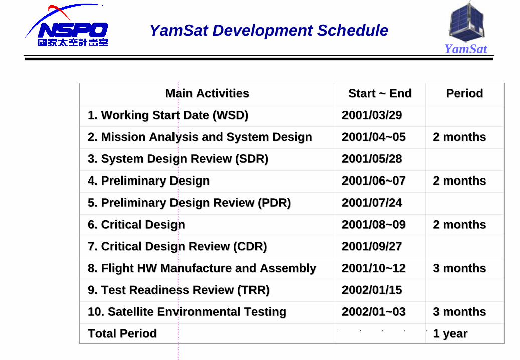
Main ActivitiesMain Activities Start ~ EndStart ~ End PeriodPeriod
1. Working Start Date (WSD)1. Working Start Date (WSD) 2001/03/292001/03/29
2. Mission Analysis and System Design2. Mission Analysis and System Design 2001/04~052001/04~05 2 months2 months
3. System Design Review (SDR)3. System Design Review (SDR) 2001/05/282001/05/28
4. Preliminary Design4. Preliminary Design 2001/06~072001/06~07 2 months2 months
5. Preliminary Design Review (PDR)5. Preliminary Design Review (PDR) 2001/07/242001/07/24
6. Critical Design6. Critical Design 2001/08~092001/08~09 2 months2 months
7. Critical Design Review (CDR)7. Critical Design Review (CDR) 2001/09/272001/09/27
8. Flight HW Manufacture and Assembly8. Flight HW Manufacture and Assembly 2001/10~122001/10~12 3 months3 months
9. Test Readiness Review (TRR)9. Test Readiness Review (TRR) 2002/01/152002/01/15
10. Satellite Environmental Testing10. Satellite Environmental Testing 2002/01~032002/01~03 3 months3 months
Total PeriodTotal Period 1 year1 year
YamSat
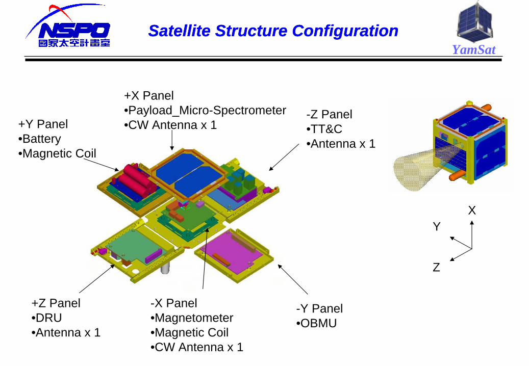
+Y Panel•Battery•Magnetic Coil
-X Panel•Magnetometer•Magnetic Coil•CW Antenna x 1
-Z Panel•TT&C•Antenna x 1
+X Panel•Payload_Micro-Spectrometer•CW Antenna x 1
-Y Panel•OBMU
+Z Panel•DRU•Antenna x 1
XY
Z
Satellite Structure ConfigurationSatellite Structure Configuration

YamSatElectrical Block Diagram
Micro-Controller
80C52
D/AConverter
OPAmp.
MagneticCoil #1, #2
A/DConverter
OPAmp.
3-axisMagneto-
meter
CW Generator
FSKModulator
FSKDemodulatorReceiver
Transmitter
DiplexerCoupler
BatteryBattery
Micro-Spectrometer
RAM32KBytes
Solar Array
...
x 6Solar Array
...
x 6
DC/DCConverter
PowerDistribution
PowerMonitor& WDT
TemperatureSensor
CurrentTelemetry
VoltageTelemetry
BilevelOutput
BilevelInput
FiberCoupler
3.75V+5V, -5V
To Units
Rx
Rx
Bi
145.85MHz
145.85MHz
29.355MHz
BiCoupler
YamSat
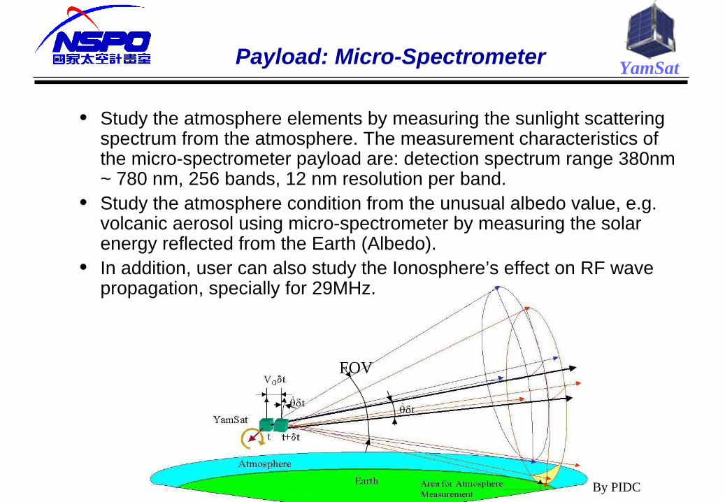
t
FOV
t
Payload: Micro-Spectrometer
By PIDC
• Study the atmosphere elements by measuring the sunlight scattering spectrum from the atmosphere. The measurement characteristics of the micro-spectrometer payload are: detection spectrum range 380nm ~ 780 nm, 256 bands, 12 nm resolution per band.
• Study the atmosphere condition from the unusual albedo value, e.g. volcanic aerosol using micro-spectrometer by measuring the solar energy reflected from the Earth (Albedo).
• In addition, user can also study the Ionosphere’s effect on RF wave propagation, specially for 29MHz.
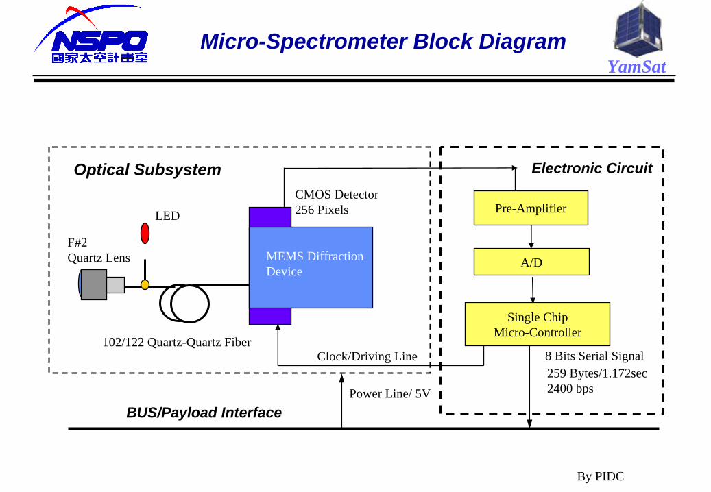
YamSatMicro-Spectrometer Block Diagram
By PIDC
102/122 Quartz-Quartz Fiber
CMOS Detector256 Pixels
MEMS DiffractionDevice
LED Pre-Amplifier
A/D
Single ChipMicro-Controller
BUS/Payload InterfacePower Line/ 5V
F#2Quartz Lens
Clock/Driving Line 8 Bits Serial Signal
Optical Subsystem Electronic Circuit
259 Bytes/1.172sec2400 bps
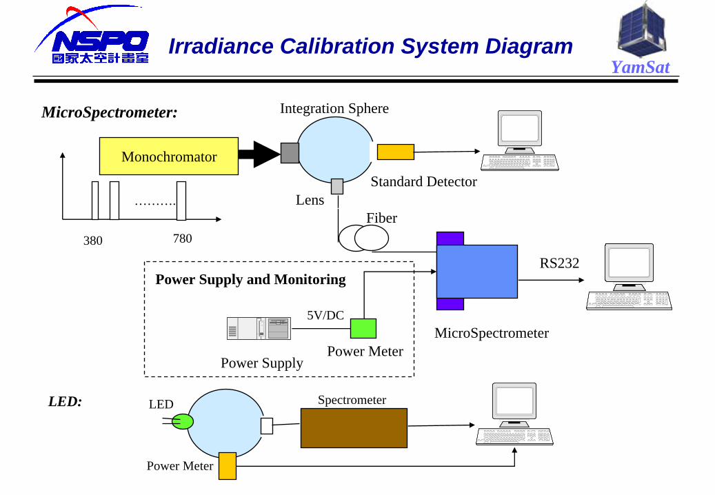
YamSatIrradiance Calibration System Diagram
Integration Sphere
Monochromator
MEMS DiffractionDevice
Standard DetectorLens
Fiber
MicroSpectrometer
RS232
Power Supply
5V/DC
Power Meter
MicroSpectrometer:
LED: LED
Power Meter
Spectrometer
Power Supply and Monitoring
……….
380 780

YamSatYamsat Stress Distribution
YamSat
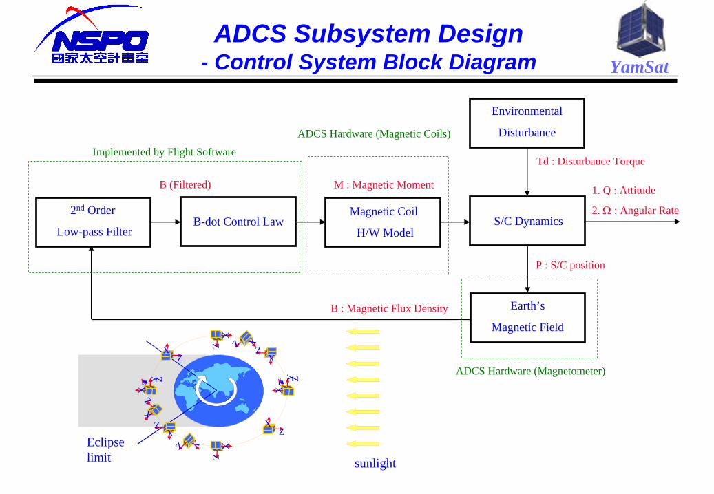
ADCS Subsystem Design- Control System Block Diagram
Environmental
Disturbance
S/C DynamicsMagnetic Coil
H/W ModelB-dot Control Law
2nd Order
Low-pass Filter
Earth’s
Magnetic FieldB : Magnetic Flux Density
B (Filtered)
Implemented by Flight Software
ADCS Hardware (Magnetic Coils)
ADCS Hardware (Magnetometer)
1. Q : Attitude
2.
: Angular Rate
M : Magnetic Moment
Td : Disturbance Torque
P : S/C position
Eclipse limit sunlight
ZX
ZX
Z- YX
ZX
ZX
Z X
Z X
ZX
ZX
Z- YX
ZX

YamSatFSW Executive Loop – Flow Diagrams
Reset Initialization
Command ISR
PayloadData ISR
Executive Loop
Executive LoopInitialization
Timer ISR
CMD Reception
Task
CMDProcessing
Task
P/L DataReception
Task
P/L DataStorage
Task
Actuator Output
Task
TelemetryPacket
Task
ADCSTask
EPSTask
TelemetryTransmit
Task
SensorInputTask
BackgroundBuilt-in
Task
CRCChecking
Task
CMDexecution
Task
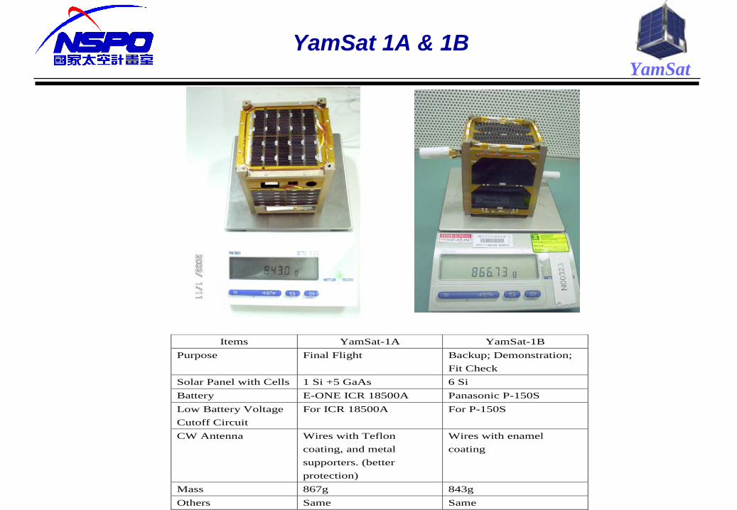
YamSatYamSat 1A & 1B
Items YamSat-1A YamSat-1B Purpose Final Flight Backup; Demonstration;
Fit Check Solar Panel with Cells 1 Si +5 GaAs 6 Si Battery E-ONE ICR 18500A Panasonic P-150S Low Battery Voltage Cutoff Circuit
For ICR 18500A For P-150S
CW Antenna Wires with Teflon coating, and metal supporters. (better protection)
Wires with enamel coating
Mass 867g 843g Others Same Same
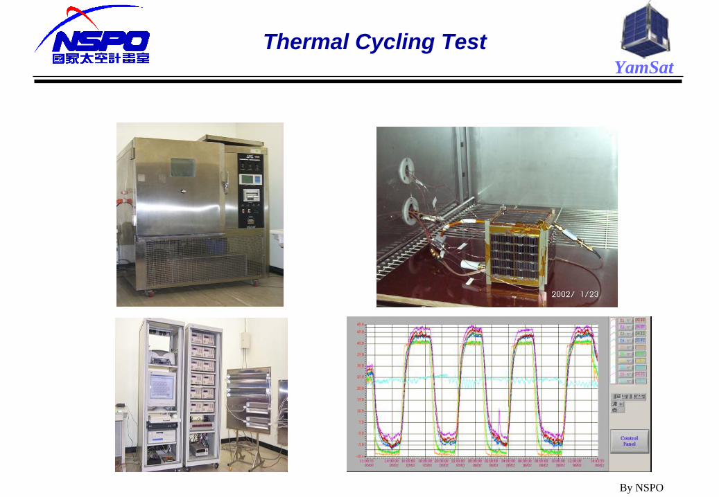
YamSatThermal Cycling Test
By NSPO
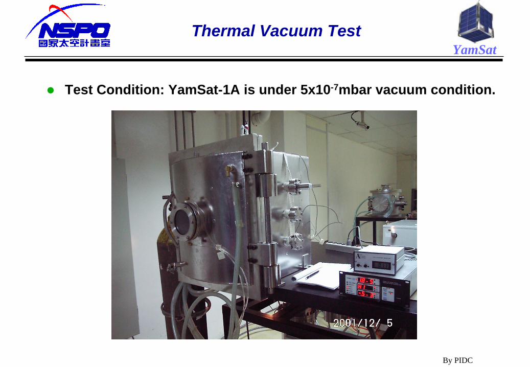
YamSatThermal Vacuum Test
Test Condition: YamSat-1A is under 5x10⁻⁷mbar vacuum condition.
By PIDC
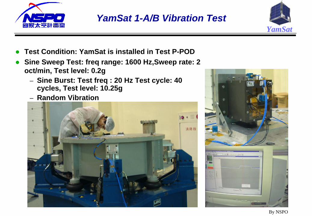
YamSatYamSat 1-A/B Vibration Test
Test Condition: YamSat is installed in Test P-POD
Sine Sweep Test: freq range: 1600 Hz,Sweep rate: 2 oct/min, Test level: 0.2g
– Sine Burst: Test freq : 20 Hz Test cycle: 40 cycles, Test level: 10.25g
– Random Vibration
By NSPO

YamSatGround Systems to YamSat End-to-End Test
One amateur ground station uses two YAGI antennas for VHF communication with 12dBi-antenna gain and 100W-transmitter power to receive both YamSat telemetry and Morse code signal sent from the amateur communication payload.
Continuous wave (CW) circuit generates tracking beacon and SOH data under the control of the on-board controller.
The Call sign of the ground station is “BN0SPO” and the call sign of the YamSat is “BN01A”.
By NSPO
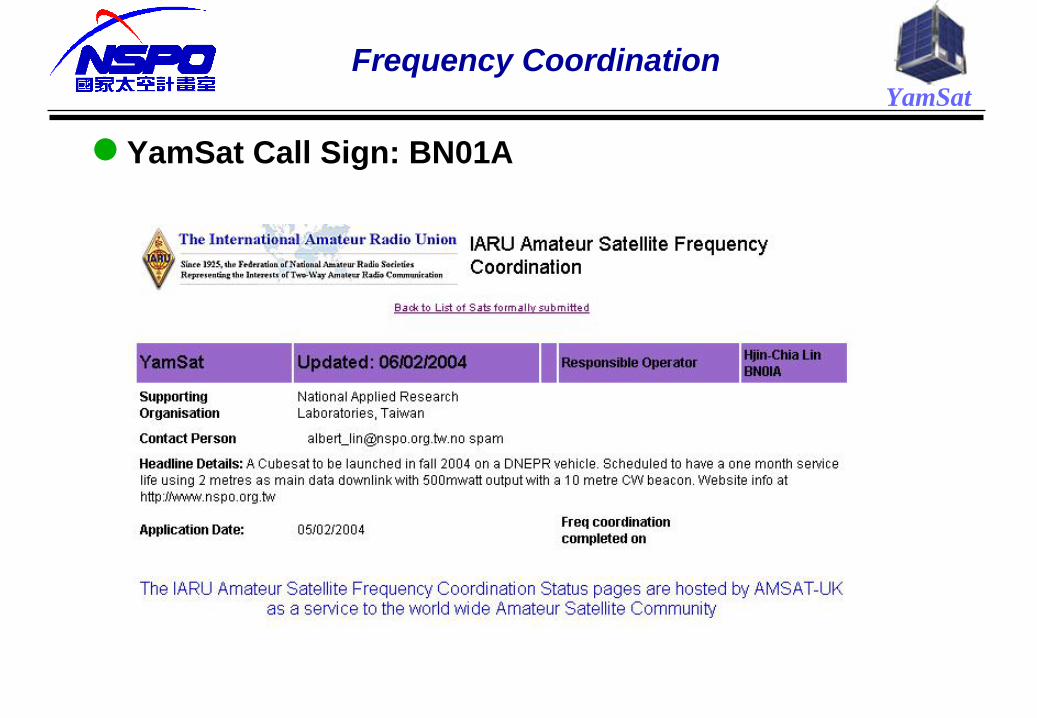
YamSatFrequency Coordination
YamSat Call Sign: BN01A
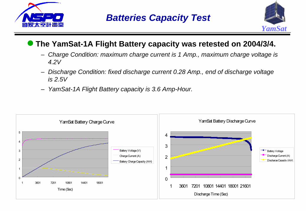
YamSatBatteries Capacity Test
The YamSat-1A Flight Battery capacity was retested on 2004/3/4. – Charge Condition: maximum charge current is 1 Amp., maximum charge voltage is
4.2V– Discharge Condition: fixed discharge current 0.28 Amp., end of discharge voltage
is 2.5V– YamSat-1A Flight Battery capacity is 3.6 Amp-Hour.
YamSat Battery Discharge Curve
0
1
2
3
4
1 3601 7201 10801 14401 18001 21601Discharge Time (Sec)
Battery VoltageDischarge Current (A)Discharge Capacity (AH)
YamSat Battery Charge Curve
0
1
2
3
4
5
1 3601 7201 10801 14401 18001
Time (Sec)
Battery Voltage (V)
Charge Current (A)
Battery Charge Capacity (AH)
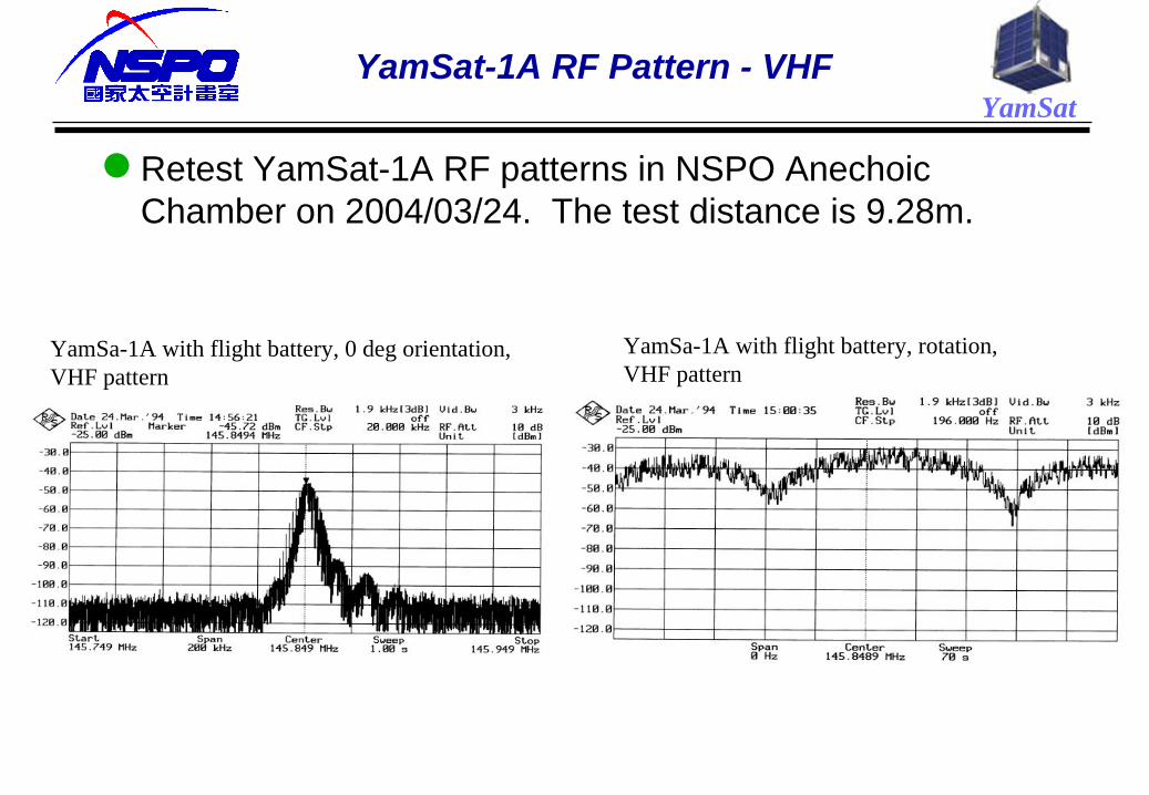
YamSatYamSat-1A RF Pattern - VHF
Retest YamSat-1A RF patterns in NSPO Anechoic Chamber on 2004/03/24. The test distance is 9.28m.
YamSa-1A with flight battery, 0 deg orientation,VHF pattern
YamSa-1A with flight battery, rotation,VHF pattern
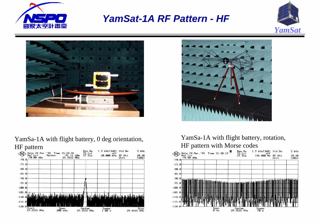
YamSatYamSat-1A RF Pattern - HF
YamSa-1A with flight battery, 0 deg orientation,HF pattern
YamSa-1A with flight battery, rotation,HF pattern with Morse codes
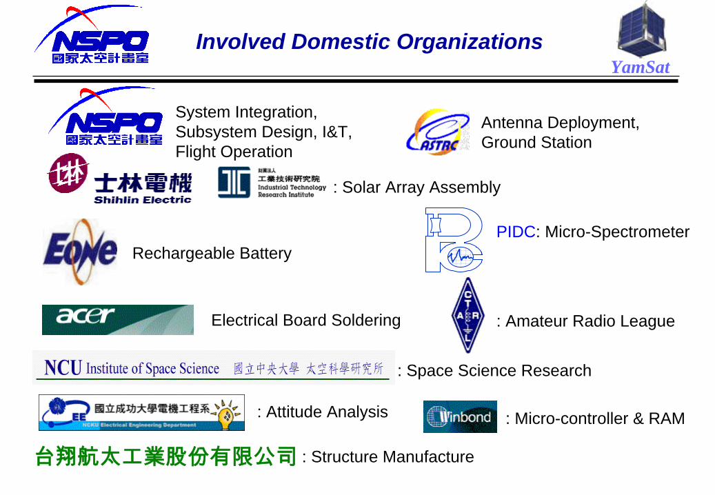
YamSatInvolved Domestic Organizations
Rechargeable Battery
台翔航太工業股份有限公司 : Structure Manufacture
: Attitude Analysis
: Space Science Research
Electrical Board Soldering
: Micro-controller & RAM
: Solar Array Assembly
: Amateur Radio League
Antenna Deployment, Ground Station
System Integration, Subsystem Design, I&T, Flight Operation
PIDC: Micro-Spectrometer