ycw 700 thermal clip curtain wall system - ykk ap home prime · 2015-10-25 · page-ii effective...
TRANSCRIPT
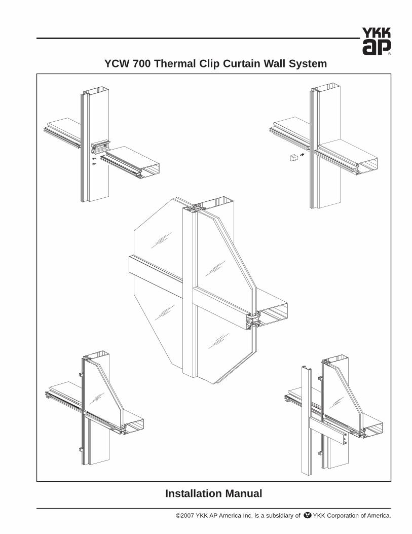
YCW 700 Thermal Clip Curtain Wall System
Installation Manual
©2007 YKK AP America Inc. is a subsidiary of YKK Corporation of America.


Effective Date: November 6, 2007 Page-i
YCW 700 Thermal Clip Curtain Wall System
TABLE OF CONTENTS
Installation Notes . . . . . . . . . . . . . . . . . . . . . . . . . . . . . . . . . . . . . . . . Page ii
PARTS DESCRIPTIONYCW 700 Framing Members . . . . . . . . . . . . . . . . . . . . . . . . . . . . . . . Page 1 YCW 700 Accessories . . . . . . . . . . . . . . . . . . . . . . . . . . . . . . . . . . . . Page 2 & 3
FRAME FABRICATIONFrame Types/Anchoring Methods . . . . . . . . . . . . . . . . . . . . . . . . . . . . Page 4 & 5Fabrication of Vertical Mullions . . . . . . . . . . . . . . . . . . . . . . . . . . . . . . Page 6Shear Clips/“J” Anchors for Horizontals . . . . . . . . . . . . . . . . . . . . . . . Page 7Using Optional Steel Reinforcement . . . . . . . . . . . . . . . . . . . . . . . . . Page 8Using Optional Reinforcement Sleeve . . . . . . . . . . . . . . . . . . . . . . . . Page 9Fabrication of Horizontals . . . . . . . . . . . . . . . . . . . . . . . . . . . . . . . . . . Page 10Fabrication of Head and Sill . . . . . . . . . . . . . . . . . . . . . . . . . . . . . . . . Page 11 & 12Fabricate Face Covers . . . . . . . . . . . . . . . . . . . . . . . . . . . . . . . . . . . . Page 13Fabricate Vertical for Splices . . . . . . . . . . . . . . . . . . . . . . . . . . . . . . . Page 14
FRAME INSTALLATIONTypical Vertical Splice . . . . . . . . . . . . . . . . . . . . . . . . . . . . . . . . . . . . . Page 15Install Mullion End Caps . . . . . . . . . . . . . . . . . . . . . . . . . . . . . . . . . . . Page 16Install Jamb & Vertical Mullions . . . . . . . . . . . . . . . . . . . . . . . . . . . . . Page 17Install Dead Load/Wind Load Anchors . . . . . . . . . . . . . . . . . . . . . . . . Page 18 & 19Attach Horizontal Members . . . . . . . . . . . . . . . . . . . . . . . . . . . . . . . . Page 20 to 22Standard Mullion 90° Corner Assembly . . . . . . . . . . . . . . . . . . . . . . . Page 23SSG Mullion 90° Corner Assembly . . . . . . . . . . . . . . . . . . . . . . . . . . . Page 24 & 25Perimeter Sealant . . . . . . . . . . . . . . . . . . . . . . . . . . . . . . . . . . . . . . . . Page 26
GLAZINGInstall Joint Plugs . . . . . . . . . . . . . . . . . . . . . . . . . . . . . . . . . . . . . . . . Page 27 & 28Install 1/4” Glazing Adaptors . . . . . . . . . . . . . . . . . . . . . . . . . . . . . . . . Page 28 & 29Install Interior Glazing Gaskets/Spacers . . . . . . . . . . . . . . . . . . . . . . . Page 30Glazing Clip, Setting Block & Glass Installation . . . . . . . . . . . . . . . . Page 31 & 32Install Exterior Glazing Gaskets . . . . . . . . . . . . . . . . . . . . . . . . . . . . . Page 32Install Water Deflectors & Face Covers . . . . . . . . . . . . . . . . . . . . . . . Page 33Structural Silicone Glazing . . . . . . . . . . . . . . . . . . . . . . . . . . . . . . . . . Page 34
DOOR SUB-FRAME INSTALLATIONInstall Door Sub-Frame . . . . . . . . . . . . . . . . . . . . . . . . . . . . . . . . . . . Page 35
Effective Date: November 6, 2007Page-ii
YCW 700 Thermal Clip Curtain Wall System
1. Do not drop, roll or drag boxes of aluminum framing. Move and stack boxes with proper supportto prevent distortion. If fork lifts are used be especially careful about striking the boxes when lifting or moving.
2. Store in a dry, out of the way area. If rain exposure, condensation or any water contact is likely,then all packaging material should be removed. Wet packaging materials will discolor and may stainaluminum finishes and paints.
3. All materials should be checked for quality and quantity upon receipt, YKK AP must be notified immediately of any discrepancies in shipment. Check to make sure that you have the requiredshims, sealants, supplies and tools necessary for the installation.
4. Carefully check the openings and surrounding conditions that will receive your material.Remember, if the construction is not per the construction documents, it is your responsibility to notify the general contractor in writing. Any discrepancies must be brought to the general contractor's attention before you proceed with the installation.
5. Gather your shop drawings, materials, packing list, and this installation manual. Carefully reviewparts location, the sequence it goes therein, when you glaze it and how you seal it. Installationinstructions are of a general nature and may not cover every condition you will encounter. The shopdrawings and/or installation manuals were prepared specifically for the product.
6. Any material substitutions must be of equal or greater quality.
7. Make certain that material samples have been sent for compatibility testing for all manufacturer'ssealants involved. Make certain sealants have been installed in strict accordance with the manufacturer's recommendations and specifications.
8. Remember to isolate, in an approved manner, all aluminum from uncured masonry or otherincompatible materials.
9. System-to-structure fasteners are not supplied by YKK AP. Fasteners called out on shop drawings are to indicate minimum sizes for design loading.
10. Entrances are to be installed plumb, square, level and true.
11. If any questions arise concerning YKK AP products or their installation, contact YKK AP for clarification before proceeding.
12. YKK AP storefront and/or curtain wall framing is typically completed before drywall, flooring andother products which may still be in process. Take the extra time to wrap and protect the work thatyou have proudly produced, because no one else will.
13. Cutting tolerances are plus zero (0”), minus one thirty second (-1/32”) unless otherwise noted.
14. Check our website, www.ykkap.com, for the latest installation manual update prior to commencing work.
Installation Notes

Effective Date: November 6, 2007 Page-1
YCW 700 Thermal Clip Curtain Wall System
FRAMING MEMBERS
Vertical/HorizontalFor 1” Glazing2-1/4” x 4-15/16”
E9-3201
Head, Sill, HorizontalFor 1” Glazing2-1/4” x 4-15/16”
E9-3202
E9-3205Vertical/HorizontalFor 1/4” Glazing2-1/4” x 4-15/16”
SSG Vertical MullionFor 1/4” & 1” Glazing2-1/4” x 4-15/16”
E9-3207
1/4” Glazing Adaptor E9-3204
SSG 1/4” GlazingAdaptor E9-3208
Face Cover E9-3211
Perimeter Face CoverFor 1” glazing
E9-3212
Interior Mullion CoverUse with E9-1618 E9-3214
Flush Filler1” Glazing
E9-3215
Flush Filler1/4” Glazing E9-3216
Door Jamb1” Glazing E9-3217
Door Jamb1/4” Glazing E9-3218
SSG Tongue AdaptorFor 1” Glazing
E9-3219
SSG 90° OutsideCorner Trim E9-2348
Angle (1-1/2” x 1-1/2”)For 90° Corner E9-9303
Angle (1” x 1”)For 90° Corner E9-9302
Snap in Door Stop AS-0417
Head, Sill, HorizontalFor 1/4” Glazing2-1/4” x 4-15/16”
E9-3206
Flush FillerUse with E9-3202,& E9-3206
E9-3203
SSG 90° CornerAdaptor E9-3209
E9-3220
Perimeter Face CoverFor 1/4” glazing E9-3213
SSG Tongue AdaptorFor 1/4” Glazing
90° Corner InteriorSnap Cover BaseUse with E9-3214
E9-1618

Effective Date: November 6, 2007Page-2
YCW 700 Thermal Clip Curtain Wall System
ACCESSORIES
Shear Clip E1-1301
Shear Clip/“J”Anchor E1-1302
Mullion Splice Sleeve6” Long E1-1303
Left Joint PlugFor SSG 90° Corner1/4” Glazing
E1-1313
E1-1314
Shear ClipFor SSG 90° Mullion E1-1315
MullionReinforcement Sleeve29” Long
E1-1304
Splice Sleeve For Face Cover E1-1305
Splice SleeveFor Perimeter FaceCover, 1” Glazing
E1-1306
E1-1316
E1-1317
Shear AngleFor SSG 90° Corner E1-1318
Splice SleeveFor Perimeter FaceCover, 1/4” Glazing
E1-1307
Mullion “T” Anchor E1-1308
Jamb “F” Anchor E1-1309
E1-1319Mullion “T” AnchorFor SSG 90° Corner Mullion
E1-1320
Wind load Anchor E1-1204
Mullion End CapFor 1” Glazing E1-1310
Mullion End CapFor 1/4” Glazing E1-1311
Joint PlugFor SSG 90° Corner1” Glazing
E1-1312
Dead load Anchor E1-1205
Interior/Exterior Gasket E2-0330
Water Deflector E2-0331
Right Joint PlugFor SSG 90° Corner1/4” Glazing
Shear Clip/“J”AnchorFor SSG 90° Corner
Shear Clip/“J”AnchorFor SSG 90° Corner
Shear AngleFor SSG 90° Corner
SSG Glazing Spacer E2-0176
Wind Load / Dead LoadAnchor Slip Pad E3-0103

Effective Date: November 6, 2007 Page-3
YCW 700 Thermal Clip Curtain Wall System
ACCESSORIES/FASTENERS
Joint PlugFor 1” Glazing E2-0332
E2-0333
E2-0334
E3-0006
#8 x 3/8” PHSMS Type AB, For attachmentof E9-2348 to E9-3209
PC-0806
E2-0335
Isolator Tape(1/8” x 7/16”) Use withE9-3212 & E9-3213
E2-0239
E2-0356
PC-1006
PC-1010
#10 x 1-1/2” PHSMS Type AB, For attachmentof E9-3209 to E9-3207
PC-1024
Side BlockFor 1” Glazing E2-0134
Setting BlockFor 1/4” Glazing E2-0192
PC-1208
#12 x 5/8” FHSMSType AB, For attachmentof splice sleeve, E1-1303
FC-1210
#12 x 1-1/4” FHSMS Type AB, For attachmentof horizontal to shear clip
FC-1220
Side BlockFor 1/4” Glazing E2-0623
Thermal Clip E3-0040
TemporaryGlass Retainer E3-0041
1/4” - 20 x 5/8” HWHSType F, For attachmentof shear clip to vertical
HF-2510-W1
1/4” - 20 x 1” HWHSType F, For attachmentof shear clip to vertical
HF-2516-W1
1/4” Flat WasherFor attachment of shearangle to SSG 90° vertical
WW-2500
SSG Temporary GlassRetainerFor 1/4” Glazing
#10 x 3/8” PHSMSType AB, For attachmentof E9-1618 to mullion
#10 x 5/8” PHSMSType AB, For attachmentof E9-3208 to E9-3207
#12 x 1/2” PHSMSType AB, For attachmentof 90° corner shear clips
Joint PlugFor 1/4” Glazing
SSG Joint PlugFor 1” Glazing
SSG Joint PlugFor 1/4” Glazing
Isolator Tape(1/8” x 11/16”) Use with90° Inside Corner
SSG Temporary GlassRetainerFor 1” Glazing
E3-0001
FF-0808SS#8-32 x 1/2” FHTCSType F, For attachmentof face cover splice
Setting BlockFor 1” Glazing E2-0178
Setting Block ChairFor 1” Glazing Sill at End Bay
E1-1321

Effective Date: November 6, 2007Page-4
YCW 700 Thermal Clip Curtain Wall System
FRAME FABRICATION
FRAME TYPES / ANCHORING METHODS
The following is a guideline for commontypes of frames. Refer to shop drawings forexact layout of frames.
Note: If YKK does not prepare the shopdrawings for the project, a qualified engineermust approve all anchors and mullions forwind load and dead load.
All anchors must be attached to structurallysound material that will accommodate theanchor reactions.
*Vertical end attachment will be “J” anchor or mullion end anchor.
Smaller units may be assembled on theground and tipped into place.
Fabrication of YCW 700 varies depending on the type of vertical end attachment required for a given project:
“J” Anchors, E1-1302, are for medium load conditions.
Mullion End Anchors “F”, E1-1309, & “T”, E1-1308, are for high load conditions.
Larger units require being stick assembled withopen back horizontals used in the last bay.

Effective Date: November 6, 2007 Page-5
YCW 700 Thermal Clip Curtain Wall System
FRAME FABRICATIONUsing Mullion End Anchors:
YCW 700 has three possible end anchoringconditions: “J”, “T”, and “F”.Anchors depend on end reactions, stress and attachment.
Mullions should be preassembled with shearclips, end anchors, and steel or aluminumreinforcing if necessary.
Framing members:-Open back members, E9-3202 & E9-3206,are used for all head and sill members.
-Closed horizontal members, E9-3201 &E9-3205, are used for all intermediatehorizontals with the exception of end bays.
-Open back members, E9-3202 & E9-3206,are used for intermediate horizontals atend bays, to slide over the shear clips.
Note: When using stick built construction, check for plumb, level, and overallframe width every fifth mullion. This helps to avoid the build up ofcumulative tolerance errors. Also check that all anchors are secureand firmly attached to the building.

Effective Date: November 6, 2007Page-6
YCW 700 Thermal Clip Curtain Wall System
FRAME FABRICATIONFABRICATE VERTICAL MULLIONS
STEP 1-Cut all vertical and jamb mullions to frame height as shown on shop drawings. Allow for 1/2” caulk joint around the frame & 1/2” joint at vertical splices.See Detail 1.
STEP 2-Mullion hole locations for shear clips, E1-1301, and “J” anchor clip, E1-1302,are shown below.
-Drill 0.213” (#3) dia. holes for HF-2510-W1 fasteners at the locations indicated.See Detail 1.
Note: Hole locations for shear clips and “J” anchors are the same.
Detail 11” Glazing Shown
1/4” Glazing Similar
Effective Date: November 6, 2007 Page-7
YCW 700 Thermal Clip Curtain Wall System
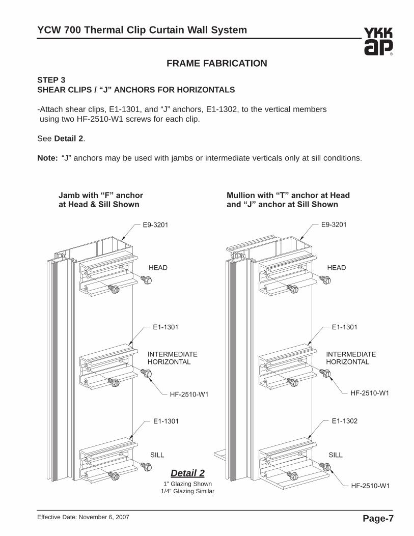
FRAME FABRICATIONSTEP 3SHEAR CLIPS / “J” ANCHORS FOR HORIZONTALS
-Attach shear clips, E1-1301, and “J” anchors, E1-1302, to the vertical members using two HF-2510-W1 screws for each clip.
See Detail 2.
Note: “J” anchors may be used with jambs or intermediate verticals only at sill conditions.
Detail 21” Glazing Shown
1/4” Glazing Similar

Effective Date: November 6, 2007Page-8
YCW 700 Thermal Clip Curtain Wall System
FRAME FABRICATIONSTEP 4USING OPTIONAL STEEL REINFORCING
If engineering calculations require the vertical mullions to be reinforced with steel, secure thereinforcing to the vertical using appropriate fasteners.-Start 3” from both ends of the mullion and install a flathead fastener on both sides of the throat.-Stagger the fasteners on either side of the throat going up the vertical, maximum 12” apart.-Seal all screw heads with sealant.
Optional reinforcing is also attached on the sides of themullion with the attachment of shear clips and “J” anchors.-Drill 0.281” (9/32) dia. clear holes in mullion only as shownin Detail 1.
-Match drill 0.213 (#3) dia. tap holes in the reinforcing only.-Attach shear clips/“J” anchors using HF-2516-W1 screws.See Detail 3.Note: Exact size of reinforcing and the size and location of
fasteners to be determined by a qualified engineer.
Detail 31” Glazing Shown
1/4” Glazing Similar

Effective Date: November 6, 2007 Page-9
YCW 700 Thermal Clip Curtain Wall System
FRAME FABRICATIONSTEP 5USING OPTIONAL REINFORCEMENT SLEEVE, E1-1304
If engineering calculations require the vertical mullions to be reinforced with additionalaluminum, E1-1304, reinforcement sleeve may be used at wind load / dead load points. Checking stress levels at point load areas will require different anchors or possibly steel reinforcing. A qualified engineer, should do these calculations.
-Reference your shop drawings for the exact location of the centerline of the wind load / dead load anchors.
-From the centerline measure down 14-5/8” along the “V-groove” of the screw raceway on the face of the mullion and mark the location.
-Drill a 0.189” (#12) diameter hole and install a FC-1210 fastener to properly locate the sleeve.Note: The reinforcement sleeve must be inserted into the mullion before shear clips are attached.See Detail 4.
Detail 41” Glazing Shown
1/4” Glazing Similar
Note: Wind load anchor shown,dead load anchor similar.
Effective Date: November 6, 2007Page-10
YCW 700 Thermal Clip Curtain Wall System
FRAME FABRICATION
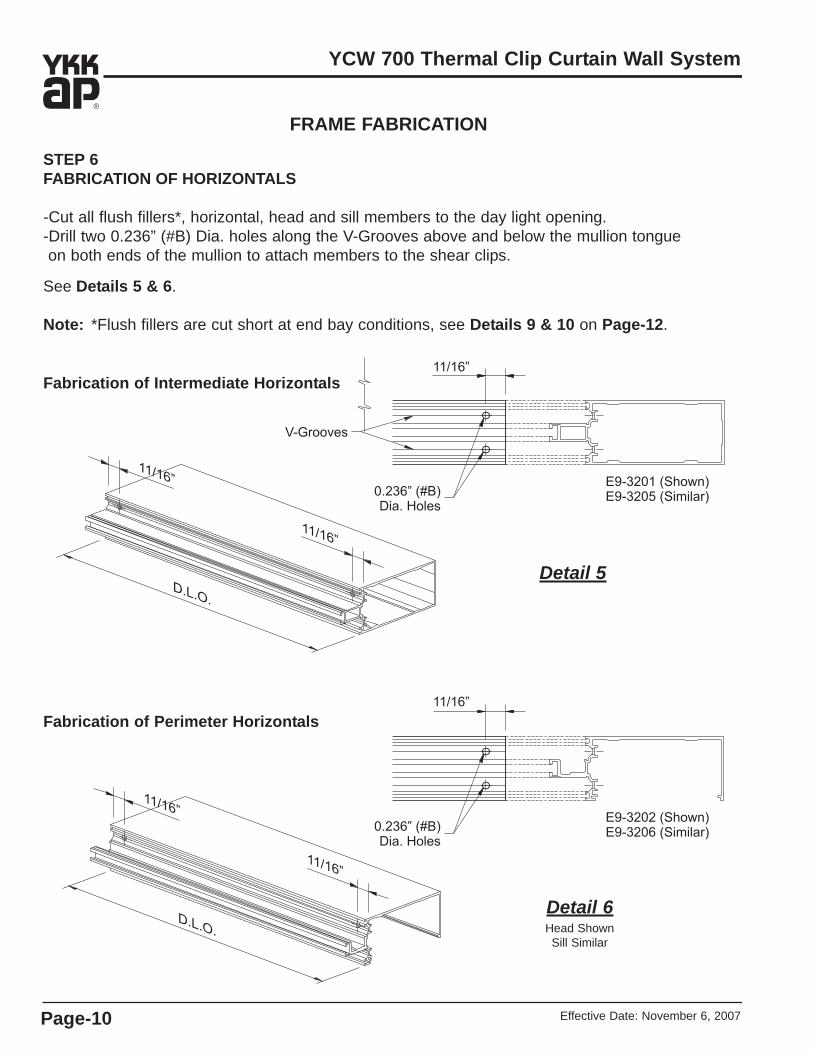
STEP 6FABRICATION OF HORIZONTALS
-Cut all flush fillers*, horizontal, head and sill members to the day light opening. -Drill two 0.236” (#B) Dia. holes along the V-Grooves above and below the mullion tongueon both ends of the mullion to attach members to the shear clips.
See Details 5 & 6.
Note: *Flush fillers are cut short at end bay conditions, see Details 9 & 10 on Page-12.
Detail 5
Fabrication of Intermediate Horizontals
Fabrication of Perimeter Horizontals
Detail 6Head ShownSill Similar

Effective Date: November 6, 2007 Page-11
YCW 700 Thermal Clip Curtain Wall System
FRAME FABRICATIONSTEP 7FABRICATION OF HEAD AND SILL
Head and sill members require additional fabrication.
Weep holes must be drilled for the head members only:-Drill 0.313” (#O) diameter weep holes 3” from each end and one in the middle of the mullion as shown in Detail 7.
Clearance holes for anchor bolts and nuts must be drilled on both head and sill members:-Drill appropriate size clearance holes on each end of the mullion to clear anchor bolts and nuts:
1-1/8” diameter holes for 3/8” bolts.1-7/16” diameter holes for 1/2” bolts.
See Details 7 & 8.
NOTE: *Consult shop drawings for exact anchor hole location and size.
Detail 7
Detail 8
Fabrication of Head Members
Fabrication of Sill Members
Effective Date: November 6, 2007Page-12
YCW 700 Thermal Clip Curtain Wall System
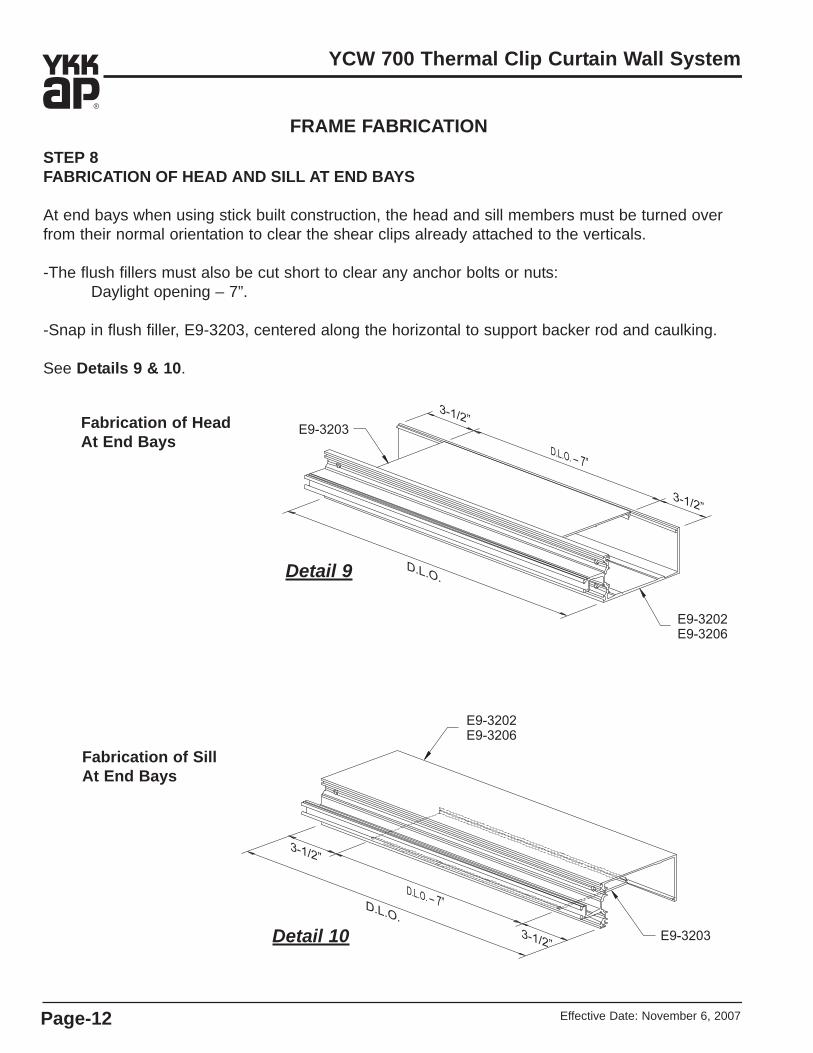
STEP 8FABRICATION OF HEAD AND SILL AT END BAYS
At end bays when using stick built construction, the head and sill members must be turned overfrom their normal orientation to clear the shear clips already attached to the verticals.
-The flush fillers must also be cut short to clear any anchor bolts or nuts:Daylight opening – 7”.
-Snap in flush filler, E9-3203, centered along the horizontal to support backer rod and caulking.
See Details 9 & 10.
FRAME FABRICATION
Detail 9
Detail 10
Fabrication of Head At End Bays
Fabrication of SillAt End Bays

Effective Date: November 6, 2007 Page-13
YCW 700 Thermal Clip Curtain Wall System
FRAME FABRICATIONSTEP 9FABRICATE HORIZONTAL FACE COVERS
-Cut all horizontal covers 1/16” less than daylight opening as shown on shop drawings. -Drill two 0.313” (#O) diameter weep holes at 1/3 points of cover. See Detail 11.
Detail 11
STEP 10FABRICATE VERTICAL FACE COVERS
-Cut all vertical covers to the same the length as the vertical mullions unless the verticals are spliced.
-Drill a 0.141” (#28) diameter hole in the vertical coversat the sill as shown in Detail 12.
-Install one PC-0806 fastener at this location to preventthe vertical covers from sliding down due to thermal expansion and contraction.
-If vertical mullions are spliced, cut covers to accommodate for 1/2” expansion joint.
-Install one PC-0806 fastener into the vertical cover at the first intermediate horizontal cover above the splice, similar to the sill condition shown in Detail 12, to prevent the face cover from sliding down.
Detail 12

Effective Date: November 6, 2007Page-14
YCW 700 Thermal Clip Curtain Wall System
FRAME FABRICATIONSTEP 11FABRICATE VERTICAL FOR SPLICES
Install splice locator screw:-From the top of the vertical measure down 2-3/4” along the screw raceway onthe face of the mullion and mark the location.
-Drill a 0.189” (#12) diameter hole for the splice locator screw.
Drill holes for splice attachment:-From the top of the vertical measure down 1” and draw a line across the side of the mullion. From the face of the mullion measure in 1” along the line and markthe location; measure in 2-3/4” from the first mark for the second hole location.
-Drill a 0.236” (#B) diameter hole at each location and countersink for a #12flathead fastener.
-Repeat the previous two steps on the other side of the vertical.
Install splice sleeve:-Install one FC-1210 fastener into the face of the mullion to properly locate the splice sleeve.
-Carefully slide the splice sleeve, E1-1303, down into the end of the mullion.
-Using the holes previously drilled in the mullion,drill 0.189” (#12) diameter pilot holes in the splice sleeve.
-Attach the splice sleeve with two FC-1210fasteners on each side of the mullion.
See Detail 13.
Detail 131/4” Glazing Shown1” Glazing Similar

Effective Date: November 6, 2007 Page-15
YCW 700 Thermal Clip Curtain Wall System
FRAME INSTALLATIONSTEP 12TYPICAL VERTICAL SPLICE
-Clean all surfaces as recommended by the sealant manufacturer.-Apply bond breaker tape to the faces of the splice sleeves.
Assemble Mullion Splice:-If using E9-3201 mullion, fill the mullion tongue cavity of the lower vertical with backer rod and press down about 1/2”. Fill the rest of the cavity with sealant and tool.
-Apply sealant to the projected portion of the splice sleeve.-Carefully slide the next mullion down onto the splice sleeve.-Use a 1/2” temporary shim to properly locate the upper mullion.-Secure upper mullion to anchor and remove temporary shim.-Apply and tool sealant onto the face and sides of the splice sleeve to create a water tight joint.
Assemble Cover Splice (installed after glazing, Step 28):-Install lower face cover.-Apply sealant to lower half of coversplice sleeve and install in lower cover using two FF-0808SS fasteners, countersunk one on each side.
-Apply bond breaker tape to upperportion of cover splice sleeve only.
-After installing upper cover, apply and tool sealant onto the face and sides of the splice sleeve.
See Detail 14.
Note: Mullions and face coversare staggered at splicelocations.
Detail 141” Glazing Shown
1/4” Glazing Similar

Effective Date: November 6, 2007Page-16
YCW 700 Thermal Clip Curtain Wall System
Seal mullion end cap watertight with sealant around vertical at top and bottom.
FRAME INSTALLATIONSTEP 13INSTALL MULLION END CAPS
-Apply sealant to the reglets at the top and bottom of the mullion prior to installing the mullion end caps:
E1-1310 for E9-3201, 1” glazing.E1-1311 for E9-3205, 1/4” glazing.
-Install the mullion end caps onto the mullion at thetop and bottom using two FC-1210 fasteners prior to erecting the verticals.
-Seal all screw heads.
-Apply and tool sealant along the intersection of the end cap and mullion at the top and bottomof the vertical.
See Detail 15.
Seal all screw heads.
Detail 151” Glazing Shown
1/4” Glazing Similar

Effective Date: November 6, 2007 Page-17
YCW 700 Thermal Clip Curtain Wall System
FRAME INSTALLATIONSTEP 14INSTALL JAMB & VERTICAL MULLIONS
-Insert mullion “T” anchors, E1-1308, and mullion “F” anchor, E1-1309, into the top and bottom of vertical mullions before erecting the mullion into the opening.
-Locate the jamb and vertical mullions and loosely attachthem to the structure.
-Field drill holes in “F”, “T” and “J” anchors for appropriate anchor bolts according to engineering calculations. Consult YKK AP if load requirements are in question.
See Detail 16.
Jamb
IntermediateVertical
Detail 161” Glazing Shown
1/4” Glazing Similar

Effective Date: November 6, 2007Page-18
YCW 700 Thermal Clip Curtain Wall System
FRAME INSTALLATIONSTEP 15INSTALL WIND LOAD / DEAD LOAD ANCHORS
-Install steel mullion anchor clips:Wind load anchor, E1-1204. See Detail 17.Dead load anchor, E1-1205. See Detail 18.
Detail 171” Glazing Shown
1/4” Glazing Similar
Detail 18
-Anchor clips are normally template or line set beforemullions are hung.
-Slotted or drilled leg of clip must be set at 90° to offset leg. See shop drawings for details of anchor attachment.
-Install plumb and align vertical mullions, drill appropriate size holes for anchor bolts as shown in shop drawings.
-Anchor bolts are fastened after horizontals are attached.-Nylon slip pads, E3-0103, must be installed betweenmullion and anchors.
SECTION A - Wind Load Anchor
SECTION B - Dead Load Anchor

Effective Date: November 6, 2007 Page-19
YCW 700 Thermal Clip Curtain Wall System
Vertical Mullion
Vertical Mullion
Lock Washer
Lock Washer
Flat Washer
Flat Washer
E3-0103Nylon Slip Pad
E3-0103Nylon Slip Pad
E1-1204Wind LoadAnchor
E1-1205Dead LoadAnchor
Hex. Nuts
Hex. Nuts
See Shop Drawings orEngineering Calculations ForCorrect Anchor and Bolt Size
(Bolts Not By YKK)
See Shop Drawings orEngineering Calculations ForCorrect Anchor and Bolt Size
(Bolts Not By YKK)
Detail 19
TYPICAL DEAD LOAD ANCHOR
TYPICAL WIND LOAD ANCHOR
Note: Drill holes in mullion centered along the slots to permit the frame to expand and contract.
STEP 15 (Continued)INSTALL WIND LOAD / DEAD LOAD ANCHORS
Detail 20
FRAME INSTALLATION
Note: Fasteners are shown forreference only; horizontalsmust be attached beforeanchor fasteners are installed.See shop drawings for bolting methods.
Effective Date: November 6, 2007Page-20
YCW 700 Thermal Clip Curtain Wall System
FRAME INSTALLATION
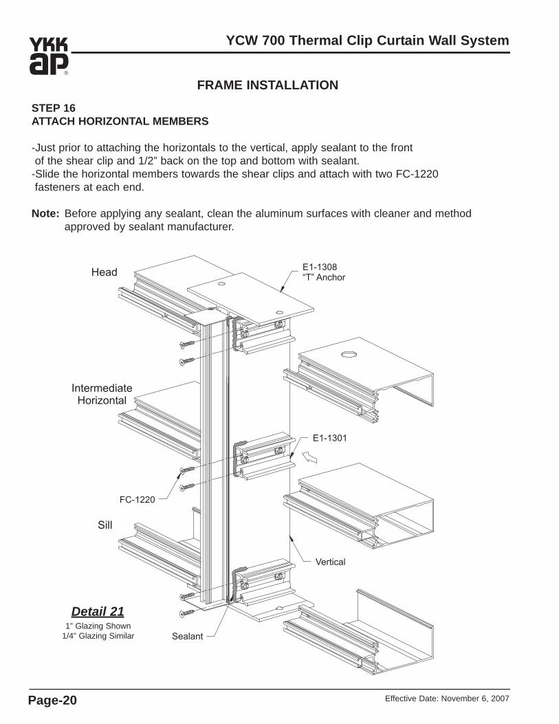
STEP 16ATTACH HORIZONTAL MEMBERS
-Just prior to attaching the horizontals to the vertical, apply sealant to the front of the shear clip and 1/2” back on the top and bottom with sealant.
-Slide the horizontal members towards the shear clips and attach with two FC-1220 fasteners at each end.
Note: Before applying any sealant, clean the aluminum surfaces with cleaner and method approved by sealant manufacturer.
Detail 211” Glazing Shown
1/4” Glazing Similar

Effective Date: November 6, 2007 Page-21
YCW 700 Thermal Clip Curtain Wall System
FRAME INSTALLATIONSTEP 16 (Continued)ATTACH HORIZONTAL MEMBERS
-Drill appropriate size holes into the structure for the anchor bolts.-Provide anchor bolts as per job requirements. See approved shop drawings or engineering calculations for appropriate anchor bolts.
-Install the anchor bolts.
Caution: There must always be a shim underthe mullion to transfer glazingdead loads to the foundation.
-Install the flush filler, E9-3203, by firstengaging the front lip and then rotating the cover down into the back snap.
See Detail 22.
Detail 221” Glazing Shown
1/4” Glazing Similar

Effective Date: November 6, 2007Page-22
YCW 700 Thermal Clip Curtain Wall System
FRAME INSTALLATION
STEP 17ATTACH HORIZONTAL MEMBERSAT END BAY
Open back horizontal members, E9-3202 (for 1” glazing) and E9-3206 (for 1/4” glazing,must be used for all horizontal conditionsat end bays in order to clear the shear clips.
-Fasten all anchor bolts at the end baybefore attaching horizontal members.
-Apply sealant to the front of the shear clip and 1/2” back on the top and bottom with sealant.
Note: Before applying any sealant, clean the aluminum surfaces with cleaner and method approved by sealant manufacturer.
-Install the intermediate horizontals by sliding the mullion under the shear clipsand up into position making sure the glazing pockets are flush.
-Attach horizontal mullions to shear clipsusing two FC-1220 fasteners at each end.
-In order to clear the shear clips, the headand sill must be turned over from theirnormal orientation (with the open backfacing the structure).
-Slide the head member up into position;slide the sill member down into position.
-Making sure the glazing pockets are flush,attach horizontal mullions to the shear clipsusing two FC-1220 fasteners at each end.
See Detail 23.
Detail 231” Glazing Shown
1/4” Glazing Similar
Effective Date: November 6, 2007 Page-23
YCW 700 Thermal Clip Curtain Wall System
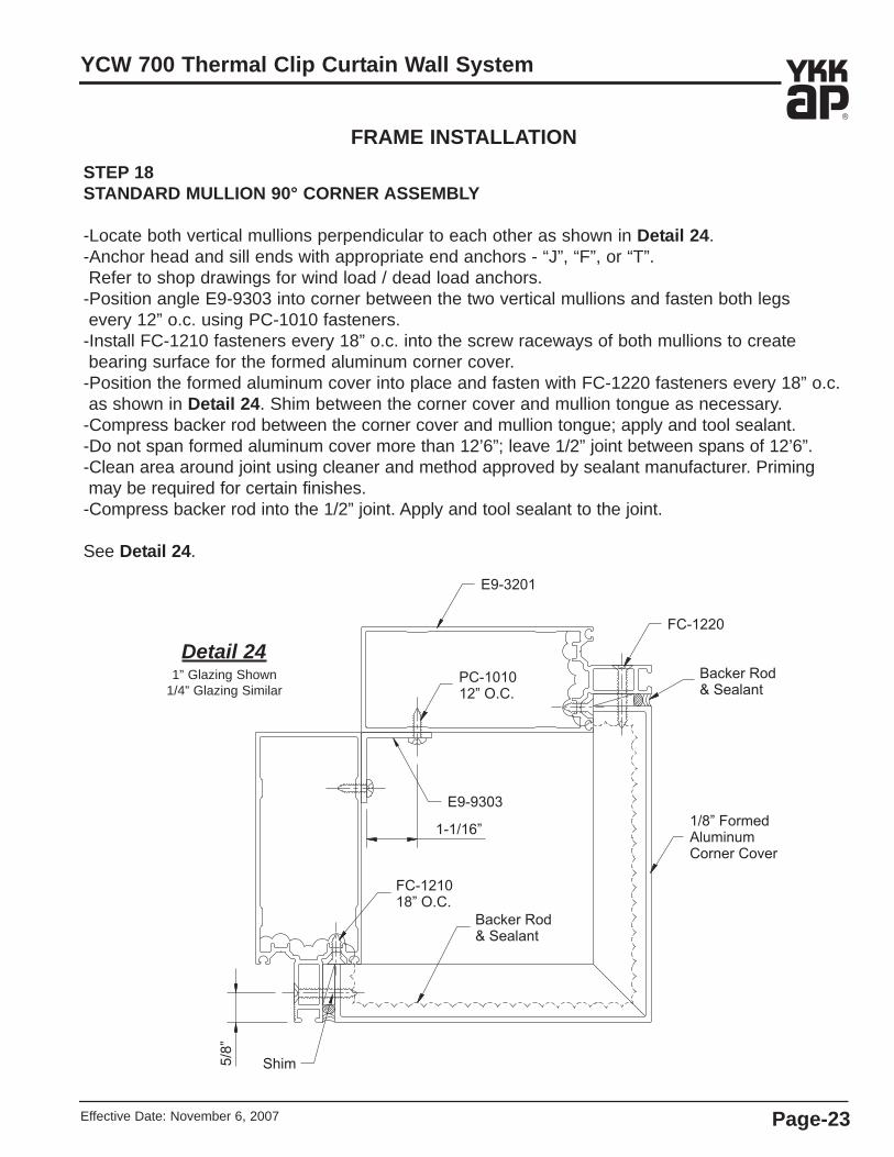
FRAME INSTALLATIONSTEP 18STANDARD MULLION 90° CORNER ASSEMBLY
-Locate both vertical mullions perpendicular to each other as shown in Detail 24.-Anchor head and sill ends with appropriate end anchors - “J”, “F”, or “T”.Refer to shop drawings for wind load / dead load anchors.
-Position angle E9-9303 into corner between the two vertical mullions and fasten both legsevery 12” o.c. using PC-1010 fasteners.
-Install FC-1210 fasteners every 18” o.c. into the screw raceways of both mullions to createbearing surface for the formed aluminum corner cover.
-Position the formed aluminum cover into place and fasten with FC-1220 fasteners every 18” o.c. as shown in Detail 24. Shim between the corner cover and mullion tongue as necessary.
-Compress backer rod between the corner cover and mullion tongue; apply and tool sealant.-Do not span formed aluminum cover more than 12’6”; leave 1/2” joint between spans of 12’6”.-Clean area around joint using cleaner and method approved by sealant manufacturer. Primingmay be required for certain finishes.
-Compress backer rod into the 1/2” joint. Apply and tool sealant to the joint.
See Detail 24.
Detail 241” Glazing Shown
1/4” Glazing Similar

Effective Date: November 6, 2007Page-24
YCW 700 Thermal Clip Curtain Wall System
FRAME INSTALLATION
STEP 19SSG MULLION 90° CORNER ASSEMBLY
-Apply a bead of sealant into both glazing reglets on the face of the SSG vertical, E9-3207.-Attach 90° corner glazing adaptor, E9-3209, to SSG vertical, E9-3207, using PC-1024 fastenersfastened every 18” o.c. and no more than 3” from each end.
-For 1” glazing 90° corner trim, E9-2348, must be attached to E9-3209 with PC 0806 fastenersevery 18” o.c. and no more than 3” from each end on both sides.
-Seal all screw heads with sealant.
-At both ends of the vertical, compress backer rod into the open cavities between the mullion and corner adaptor. Apply and tool sealant.
-Attach shear clips and/or “J” anchors according to methods previously discussed.-Insert “T” anchor, E1-1320, into the ends of the mullion.-Position the assembled mullion into place.-Attach E9-1618 interior cover base and E9-3214 cover to the back of the mullion.-Attach the horizontals as shown in Details 25, 26 and 27.
-Anchor the head and sill anchors with appropriate fasteners.
Detail 25
“T” Anchor

Effective Date: November 6, 2007 Page-25
YCW 700 Thermal Clip Curtain Wall System
FRAME INSTALLATION
STEP 19 (Continued)SSG MULLION 90° CORNER ASSEMBLY
Detail 26
Shear Clip
Detail 27
“J” Anchor

Effective Date: November 6, 2007Page-26
YCW 700 Thermal Clip Curtain Wall System
FRAME INSTALLATION
STEP 20PERIMETER SEALANT
-Position backer rod around perimeter of the frame.-Clean around the perimeter of the frame with cleaner and method approved by sealant manufacturer.
-Apply and tool sealant to the perimeter of the frame.See Detail 28.
Detail 281” Glazing Shown
1/4” Glazing Similar

Effective Date: November 6, 2007 Page-27
YCW 700 Thermal Clip Curtain Wall System
GLAZINGSTEP 21INSTALL JOINT PLUGS FOR STANDARD MULLIONS
The tongue of each horizontal mullion must be sealed to the tongue of the vertical mullion.The space between the two tongues is closed by installing joint plugs, E2-0332 for 1” glazingand E2-0333 for 1/4” glazing. Note: Joint plugs are not necessary at the sill.
-Install joint plug as shown and press firmlyagainst face of mullions.
-Apply sealant to vertical to horizontal joints.Tool sealant to completely seal corner.
See Detail 29.
Detail 291” Glazing Shown
1/4” Glazing Similar
-Clean all aluminum surfaces.-Apply sealant to all three contact sides of the joint plug.
-Apply sealant into all cavities of vertical,directly behind the joint plug.

Effective Date: November 6, 2007Page-28
YCW 700 Thermal Clip Curtain Wall System
GLAZING
STEP 22INSTALL JOINT PLUGS FOR SSG MULLIONS
The space between the SSG vertical and the two horizontal mullion tongues must be closedby installing joint plugs, E2-0334 for 1” glazing and E2-0335 for 1/4” glazing. -Clean all aluminum surfaces.-Apply sealant to all three contact sides of the joint plug. Apply and tool sealant to the twocavities on the front of the joint plug.
-Apply sealant into all cavities of vertical, directly behind the joint plug.-Install joint plug as shown and press firmly against face of mullions.-Apply sealant to vertical to horizontal joints. Tool sealant to completely seal corner.See Detail 30.
Detail 30
STEP 23INSTALL SSG 1/4” GLAZING ADAPTOR(When Required)
-Cut SSG 1/4” glazing adaptor, E9-3208, todaylight opening plus 1”.
-Position the adaptor place against the face of the SSG vertical and install with PC-1010fasteners 2” from each end and 18” o.c.
-Seal all screw heads.See Detail 30.-Install the horizontal 1/4” glazing adaptors as shown in Step 24 on Page-29.-Seal the ends of the horizontal adaptors to the vertical adaptors with sealant.

Effective Date: November 6, 2007 Page-29
YCW 700 Thermal Clip Curtain Wall System
GLAZING
STEP 24INSTALL 1/4” GLAZING ADAPTORS (When Required)
-Cut glazing adaptors for verticals:Cut Length = Daylight Opening + 1-1/2”
-Cut glazing adaptors for horizontals:Cut Length = Daylight Opening – 1/32”
-Run a bead of sealant along the gasket reglets.-Seal all exposed screw heads.
Attach the vertical glazing adaptors first:-Center the vertical adaptors in the opening.-Insert the ball end leg of the adaptor into the recess at the back of mullion tongue and rotate the snap leg into the reglet.
Attach the horizontal glazing adaptors last:-Apply sealant to the ends of the horizontal glazing adaptors.
-Install the horizontal adaptors.See Detail 31.
-Tool the excess sealant at the intersections of the adaptors to completely seal the joint.
See Detail 32.
Detail 31
Detail 32
Effective Date: November 6, 2007Page-30
YCW 700 Thermal Clip Curtain Wall System
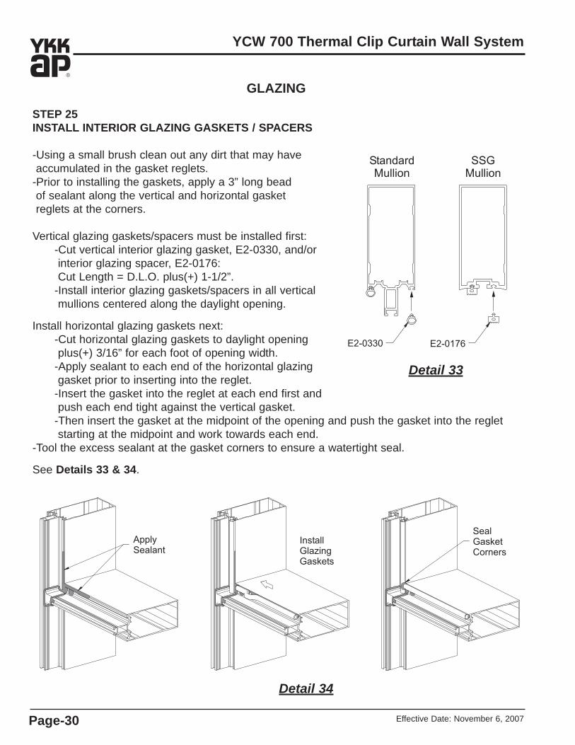
STEP 25INSTALL INTERIOR GLAZING GASKETS / SPACERS
-Using a small brush clean out any dirt that may have accumulated in the gasket reglets.
-Prior to installing the gaskets, apply a 3” long bead of sealant along the vertical and horizontal gasket reglets at the corners.
Vertical glazing gaskets/spacers must be installed first:-Cut vertical interior glazing gasket, E2-0330, and/or interior glazing spacer, E2-0176:Cut Length = D.L.O. plus(+) 1-1/2”.
-Install interior glazing gaskets/spacers in all vertical mullions centered along the daylight opening.
Install horizontal glazing gaskets next:-Cut horizontal glazing gaskets to daylight opening plus(+) 3/16” for each foot of opening width.
-Apply sealant to each end of the horizontal glazing gasket prior to inserting into the reglet.
-Insert the gasket into the reglet at each end first and push each end tight against the vertical gasket.
-Then insert the gasket at the midpoint of the opening and push the gasket into the reglet starting at the midpoint and work towards each end.
-Tool the excess sealant at the gasket corners to ensure a watertight seal.
See Details 33 & 34.
GLAZING
Detail 33
Detail 34

Effective Date: November 6, 2007 Page-31
YCW 700 Thermal Clip Curtain Wall System
GLAZINGSTEP 26INSTALL THERMAL CLIPS
Install thermal clips, E3-0040, in all horizontal and vertical mullions as shown in Detail 35.-Insert thermal clips into the front of the mullion tongue and twist 1/4 turn clockwise to engage.
-Thermal clips should be installed 3” from each end of mullion and 12” on center maximum.
STEP 27INSTALL GLASS
-Install setting blocks, E2-0178 for 1” glazing and E2-0192 for 1/4” glazing, at 1/4 points ofD.L.O. or according to engineering calculations.
*Setting block chair, E1-1321, is required forsill members at end bays.
-Install side blocks, E2-0134 for 1” glazing and E2-0623 for 1/4” glazing, at jamb and intermediate standard mullions centered along the daylight opening.
Note: Side blocks are not required for SSG mullions.-Carefully install glass into the frame. Make suresetting blocks and spacers are properly aligned with glass. See Detail 36 for glass sizes.
Detail 351” Glazing Shown
1/4” Glazing Similar
Detail 361” Glazing Shown
1/4” Glazing Similar
Effective Date: November 6, 2007Page-32
YCW 700 Thermal Clip Curtain Wall System
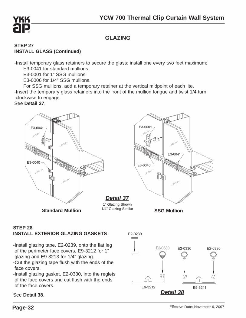
GLAZINGSTEP 27 INSTALL GLASS (Continued)
-Install temporary glass retainers to secure the glass; install one every two feet maximum:E3-0041 for standard mullions.E3-0001 for 1” SSG mullions.E3-0006 for 1/4” SSG mullions.For SSG mullions, add a temporary retainer at the vertical midpoint of each lite.
-Insert the temporary glass retainers into the front of the mullion tongue and twist 1/4 turn clockwise to engage.
See Detail 37.
Standard Mullion SSG Mullion
Detail 371” Glazing Shown
1/4” Glazing Similar
Detail 38
STEP 28INSTALL EXTERIOR GLAZING GASKETS
-Install glazing tape, E2-0239, onto the flat legof the perimeter face covers, E9-3212 for 1”glazing and E9-3213 for 1/4” glazing.
-Cut the glazing tape flush with the ends of the face covers.
-Install glazing gasket, E2-0330, into the regletsof the face covers and cut flush with the endsof the face covers.
See Detail 38.
Effective Date: November 6, 2007 Page-33
YCW 700 Thermal Clip Curtain Wall System
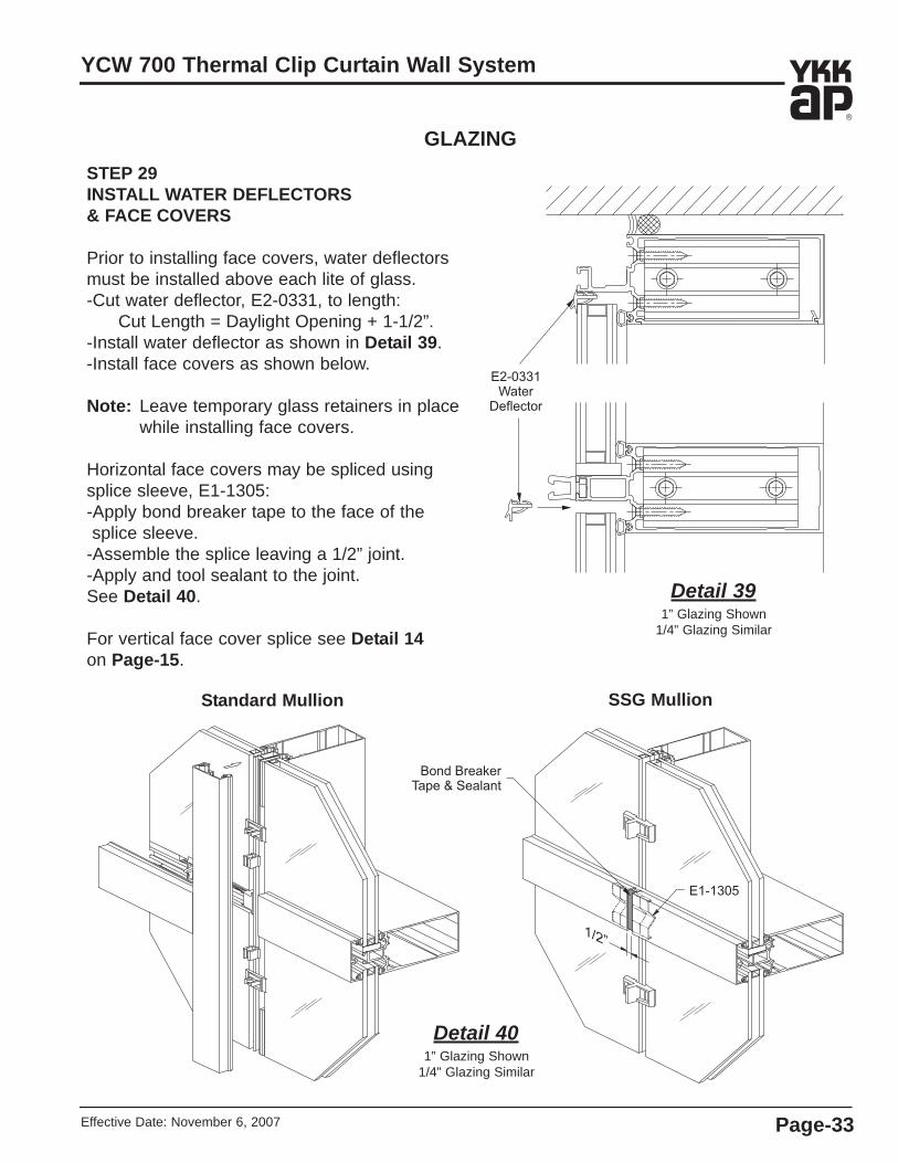
GLAZINGSTEP 29INSTALL WATER DEFLECTORS& FACE COVERS
Prior to installing face covers, water deflectorsmust be installed above each lite of glass.-Cut water deflector, E2-0331, to length:
Cut Length = Daylight Opening + 1-1/2”.-Install water deflector as shown in Detail 39.-Install face covers as shown below.
Note: Leave temporary glass retainers in placewhile installing face covers.
Horizontal face covers may be spliced usingsplice sleeve, E1-1305:-Apply bond breaker tape to the face of the splice sleeve.
-Assemble the splice leaving a 1/2” joint.-Apply and tool sealant to the joint.See Detail 40.
For vertical face cover splice see Detail 14on Page-15.
Standard Mullion SSG Mullion
Detail 401” Glazing Shown
1/4” Glazing Similar
Detail 391” Glazing Shown
1/4” Glazing Similar

Effective Date: November 6, 2007Page-34
YCW 700 Thermal Clip Curtain Wall System
GLAZINGSTEP 30STRUCTURAL SILICONE GLAZING
-Clean all silicone contact surfaces per sealant manufacturer’s recommendations.
-Apply masking tape to the mullion and glass.-Apply an approved structural silicone sealant from the bottom to top of joint making sure that the sealant completely fills the cavity.
-Using a non-scratching implement, tool the structural silicone sealant immediately after running the joint.
-Exert positive pressure while tooling to ensureproper adhesion with all surfaces.
-Immediately remove masking tape while wet;do not allow silicone to skin.
See Detail 41. Detail 411” Glazing Shown
1/4” Glazing Similar
Detail 421” Glazing Shown
1/4” Glazing Similar
-Allow structural silicone sealant to cure as recommended by sealant manufacturer(approximately two weeks).
Note: Temporary SSG retainers should beleft in place until sealant has cured.
-Once interior structural seal has cured,remove temporary retainers and insert anapproved open cell polyurethane backerrod into the glass joint.
-Clean all silicone contact surfaces per sealant manufacturer’s recommendations.
-Apply masking tape to glass and mullion.-Apply structural silicone sealant to theexterior glass joint using the same tech-nique used in sealing the interior joint.
See Detail 42.
Note: Exterior vertical seal at glass jointmust extend down and over top of the cover to cover splice.

Effective Date: November 6, 2007 Page-35
YCW 700 Thermal Clip Curtain Wall System
DOOR SUB-FRAME INSTALLATIONSTEP 31INSTALL DOOR SUB-FRAME
Doors are shipped assembled, and door sub-frames will be fabricated and shipped k.d. Please refer to theEntrances Installation Manual for door installation and follow the instructions below to install the door sub-frame:
Cut flush filler, E9-3215 for 1” glazing or E9-3216 for 1/4” glazing to door opening width and install at the transom bar as shown.
Install FC-1210 fasteners into the screw raceway even with the face of the mullion on both sides of the door jambs as shown, 2” from each end and 18” on center. Position the door sub-frame into place and fasten door jamb E9-3217 to the mullion onboth sides using PC-1010 fasteners, 3” fromeach end and 12” on center. Install door stop, AS-0417, and face covers as shown.Fasten the transom bar to the horizontal using FC-1236 fasteners as shown, 3” from each end and 12” on center. Shim between the transom bar and horizontal as needed.Apply and tool sealant between the transombar and horizontal on the exterior and interior.
Detail 431” Glazing Shown
1/4” Glazing Similar


YKK AP America Inc.7680 The BluffsSuite 100Austell, Georgia 30168www.ykkap.com