your handbook -...
TRANSCRIPT


YOUR HANDBOOK ON THE INTERNET!
CITROËN lets you view your vehicle's documentation on line, to see earlier versions and the latest information, simply and free of charge.
Connect to http://service.citroen.com :
1 | Select your language and register,
click on the link in the "Private customer access" zone to consult the vehicle documentation; a window opens providing access to all of the handbooks,
select your vehicle, choose the body type then the date of issue of the handbook,
fi nally, click on the heading of your choice.
2 |
3 |
4 |
Your vehicle is fi tted with only some of the equipment described in this document, de-pending on the trim level, version and the specifi cations for the country in which it is sold.
The fi tting of electrical equipment or ac-cessories which are not recommended by CITROËN may result in a failure of your ve-hicle's electronic system. Please note this specifi c warning and contact a CITROËN dealer to be shown the recommended equipment and accessories.
CITROËN has a presence on every continent,
a complete product range,
bringing together technology and a permanent spirit of innovation,
for a modern and creative approach to mobility.
We thank you and congratulate you on your choice.
Happy motoring!
We draw your attention to the following...
At the wheel of your new vehicle,
getting to know each system,
each control, each setting,
makes your trips, your journeys
more comfortable and more enjoyable.
Key
safety warning
contributes to the protection of the environment
refer to the page indicated

C O N T E N T S
2
Monochrome screen A 45Monochrome screen C 47Colour screen (MyWay) 50NaviDrive colour screen 52Trip computer 53
■■■■■
II - MULTIFUNCTIONSCREENS 45 55
Ventilation 56Manual air conditioning 58Digital air conditioning 60Scented air freshener 65Front seats 67Rear seats 70Seat modularity 75Mirrors 76Steering wheel adjustment 77
■■■■■■■■■
III - COMFORT 56 77
Remote control key 78Starting the engine 81Alarm 84Electric windows 86Doors 88Boot 90Opening rear screen 90Panoramic sunroof 91Fuel tank 92
■■■■■■■■■
IV - ACCESS 78 93
Lighting controls 94LED lamps 96Daytime running lamps 96Automatic illumination of headlamps 97Headlamp adjustment 98Directional lighting 99Wiper controls 100Automatic rain sensitive wipers 101Courtesy lamps 103Interior mood lighting 104
■■■■■■■■■■
V - VISIBILITY 94 104
Interior fi ttings 105Glove box 106Mats 108Boot fi ttings 111Luggage retaining net 115Torch 116
■■■■■■
VI - FITTINGS 105 116
Instrument panels 31Indicator and warning lamps 33Indicators 42
■■■
FAMILIARISATION 4 30
I - MONITORING 31 44
Child seats 117ISOFIX child seats 122Child lock 125
■■■
VII - CHILDSAFETY 117 125
Eco-driving 29■

C O N T E N T S
3
Direction indicators 126Hazard warning lamps 126Horn 126Tyre under-infl ation detection 127Braking assistance systems 128Trajectory control systems 129Emergency or assistance call 130Seat belts 131Airbags 135
■■■■■■■■■
VIII - SAFETY 126 138
Electric parking brake 139Hill start assist 146Manual gearbox 147Gear shift indicator 1486-speed electronic gearbox system 149Stop & Start 153Automatic gearbox 156Fixed centred controlssteering wheel 160Speed limiter 162Cruise control 164Parking space sensors 166Lane departure warning system 168Parking sensors 169Pneumatic suspension 171
■■■■■
■■■
■■■■■■
IX - DRIVING 139 172
Bonnet 174Running out of fuel (Diesel) 176Petrol engines 177Diesel engines 178Checking levels 179Checks 181
■■■■■■
X - CHECKS 173 182
Temporary puncture repair kit 183Changing a wheel 186Changing a bulb 190Changing a fuse 19712 V battery 203Energy economy mode 206Towing the vehicle 207Towing a trailer 209Roof bars 210Very cold climate screen 210Accessories 211
■■■■■■■■■■■
XI - PRACTICALINFORMATION 183 212
Petrol engines 213Petrol weights 214Diesel engines 215Diesel weights 217Petrol/Diesel weights - commercial versions 221Dimensions 223Identifi cation markings 226
■■■■■
■■
XII - TECHNICALDATA 213 226
Emergency or assistance 227NaviDrive 231MyWay 275Audio system 307Video pack 329
■■■■■
AUDIO andTELEMATICS 227 336
VISUALSEARCH 337 341
ALPHABETICALINDEX 342 348

4
FA
MIL
IAR
ISA
TIO
N
Xenon directional headlamps This system allows the light beams to follow the direction of the road ahead.
99
Front/rear parking sensors Sensors, located in the bumpers, de-tect obstacles.
169
Parking space sensor This system measures the size of a parking space available between two vehicles or obstacles.
166
E X T E R I O R
Stop & Start This system puts the engine tempo-rarily into standby during stops in the traffi c (red lights, traffi c jams, etc...). The engine restarts automatically as soon as you want to move off. Stop & Start reduces fuel consump-tion, exhaust emissions and noise when stationary.
153

5
FA
MIL
IAR
ISA
TIO
N
Panoramic sunroof 91
Opening rear screen 90
Pneumatic rear suspension This enhances driving comfort and maintains a constant body height, whatever the vehicle load.
171
Exterior side spotlamps These light up the zones facing the driver’s and passenger’s doors.
98
Door mirrors With electric foldback. Automatically tilts in reverse gear.
76
E X T E R I O R

6
FA
MIL
IAR
ISA
TIO
N
A. Central locking B. Unlocking C. Remote operation of lighting D. Key release/storage
Press control A , located on the switch panel to the left of the dashboard. The fuel fl ap automatically opens up fully. Insert the pump nozzle so as to push in the metal fl ap B . Push the fuel fi ller fl ap to close it.
After switching off the ignition, con-trol A is only active for a few minutes. If necessary, switch on the ignition again to reactivate it.
Bonnet stay: Unclip the stay and insert it into the notch.
78
Bonnet opening/closing To release the bonnet, pull the lever located under the dashboard towards you. Then operate the safety catch at the front of the bonnet,
174
92
Selective opening Using the multifunction screen, you can choose from the following options for opening your vehicle with the remote control: - either all of the doors and the tail-
gate, - or the driver’s door with a fi rst press,
then all of the other doors with a second press.
To close: move the stay back to its initial position, lower the bon-net, then allow it to slam shut at the end of its travel.
O P E N I N G
Remote control key Fuel tank Capacity: approximately 60 litres.

7
FA
MIL
IAR
ISA
TIO
N
This opening gives easy access to the boot, even if you are parked close to a wall or to another vehicle.
Opening rear screen
Opening
Press control 2. The grip 4 is in line with the rear wiper.
Closing Lower the rear screen.
90
Press control 1 . You cannot open the tailgate if the rear screen is already open.
Lower the tailgate, using one of the grips 3 , located on the interior tail-gate trim.
Past the balancing point, allow the tailgate to close itself (do not assist it or slow it down).
Load: 22 kg maximum. The Modubox is composed of a shop-ping trolley and a fl exible bag which can be used independently of each other depending on your needs.
112
O P E N I N G
Opening the tailgate
Closing the tailgate
Modubox (CITROËN C4 Picasso)

8
FA
MIL
IAR
ISA
TIO
N
CITROËN Grand C4 Picasso
Torch
Pneumatic rear suspension
Allows the height of the rear of the vehicle to be adjusted
Access to spare wheel
Temporary puncture repair kit Depending on model, the kit is located either in the boot well or in the compartment under the left hand second-row passenger (open the fl ap by turning the screw a quarter turn). This kit is a complete system for a temporary repair; it is made up of a compressor and a sealant car-tridge.
Luggage cover blind Luggage cover in two sections
Torch
111 112
187
171
183
116
CITROËN C4 Picasso
B O O T
Refer also to the section "Practical information - § Changing a wheel". 186

9
FA
MIL
IAR
ISA
TIO
N
6-speed electronic gearbox system This offers a fully automatic mode, a manual mode and an auto-sequential mode which combines the advan-tages of the automatic and manual modes, using the paddles behind the steering wheel.
149
Speed limiter/Cruise control These functions control the speed of the vehicle to the value that you have programmed.
162, 164
Electric parking brake For holding and releasing the vehicle. Operation is automatic with manual operation possible using the dash-board control.
139
Scented air freshener This diffuses the fragrance that you have chosen throughout the passen-ger compartment from its location in the ventilation system.
65
Interior mood lighting This soft lighting of the passenger compartment improves visibility inside the vehicle when the light is poor.
104
I N T E R I O R

10
FA
MIL
IAR
ISA
TIO
N I N S T R U M E N T S A N D C O N T R O L S

11
FA
MIL
IAR
ISA
TIO
N
8. Controls: - Trip mileage recorder reset
button - Lighting rheostat
9. Warning lamps display (with the MyWay or NaviDrive multifunction screen)
10. Electric parking brake
11. Instrument panel
12. Hazard warning lamps
13. Switch panels: - Emergency or assistance - Lane departure warning system
14. ESP deactivation button
15. Steering lock - Ignition switch
16. Multifunction screen steering mounted controls
17. Horn
1. Controls: - Lighting - Direction indicators - Front and rear foglamps
2. Paddles for automatic gearbox or 6-speed electronic gearbox system
3. Cruise control and speed limiter steering mounted controls
4. Direction indicator warning lamps
5. Audio and telematics system steering mounted controls
6. Gear lever for automatic gearbox or 6-speed electronic gearbox system
7. Controls: - Windscreen wipe - Screenwash - Rear screen wipe - Trip computer
I N S T R U M E N T S A N D C O N T R O L S
18. Optional function controls (on steering wheel)
19. Fusebox access cover
20. Controls: - Fuel fi ller fl ap - Front and rear parking sensors - Stop & Start - Volumetric alarm deactivation - Headlamp adjustment
21. Bonnet release
22. Mirror controls

12
FA
MIL
IAR
ISA
TIO
N I N S T R U M E N T S A N D C O N T R O L S

13
FA
MIL
IAR
ISA
TIO
N
I N S T R U M E N T S A N D C O N T R O L S
1. Controls: - Electric windows - Child lock
2. Side window demist vent Side air vent
3. Driver’s air conditioning controls
4. Driver’s front airbag
5. Left hand upper storage
6. Central air vents
7. Right hand upper storage
8. Front passenger’s airbag
9. Speaker (Tweeter) (right and left)
10. Quarter light glass demist vent
11. Windscreen demist vent
12. Sunshine sensor
13. Passenger’s air conditioning controls
14. Lower glovebox: - Air freshener clips - Various storage
15. Key switch: - Front passenger’s airbag
activation/deactivation
16. Central locking button
17. Audio and telematics system
18. Scented air freshener
19. Cooled storage
20. USB port (or blanking plug)
21. 12 V accessory socket or cigar lighter
22. Portable ashtray
23. Interior mood lighting control
24. Steering wheel adjustment lever

14
FA
MIL
IAR
ISA
TIO
N
Adjusting the steering wheel
The steering wheel can be adjusted for height and reach. Release the steering wheel by pulling lever A towards you. Adjust the position of the steering wheel then lock it pushing the lever fully back.
77
It automatically and progressively changes between day use and night use.
This operates with the ignition switched on. From the driver’s seat, select the door mirror by moving control 1 to the left or right, then adjust the door mirror as re-quired in four directions using control 2 . Demisting-defrosting of the door mirrors is linked to that of the rear screen.
105
76
For safety reasons, these adjust-ments must not be carried out whilst driving. This additional mirror 1 allows you to
monitor the rear passengers. It can be tilted to eliminate dazzle.
Door mirror foldback When the vehicle is parked, the door mirrors can be folded back either man-ually or automatically.
S I T T I N G C O M F O R T A B L Y
Automatic photochromic rear view mirror
Door mirror adjustment
77
Child surveillance mirror

15
FA
MIL
IAR
ISA
TIO
N
Front seats
Head restraint
Backrest angle
Seat height adjustment
Lumbar support
Forwards-backwards adjustment
Armrest
Electric adjustments Manual adjustments
68
Heated seat control (lo-cated on the inside of the front seats)
67
1. Adjustment of seat height, angle and forwards-backwards position
2. Adjustment of backrest angle and lumbar support
3. Driver: storing driving positions The seats can also be adjusted on a temporary basis: - on opening one of the front doors, - after switching on the ignition.
S I T T I N G C O M F O R T A B L Y

16
FA
MIL
IAR
ISA
TIO
N
Adjusting the seat belt height
To adjust the seat belt, squeeze the control and slide it in the direction re-quired.
131
From the driver’s seat position, the con-trols located on the door are used to op-erate the electric windows.
86
Slide the blind on the visor to the desired position by pushing at A .
The blinds are extended on the sun visor rails.
Fold the visor downwards, to pre-vent being dazzled.
Panoramic sunroof blind Opening (positions 1 to 9 ) Closing (position 0 ) The blind has an anti-pinch system.
91
S I T T I N G C O M F O R T A B L Y
Electric windows controls Sliding sun visors
105

17
FA
MIL
IAR
ISA
TIO
N
Recommended settings - Heating/manual air conditioning:
- Digital air conditioning: the fully automatic mode is recommended - press "AUTO" .
Operate For...
Cooling or Fully cold to start, then personal settings
Maximum to start, then personal settings
ON ON when
starting, then OFF
Heating or Fully hot to start, then personal settings
Maximum to start, then personal setting
ON when
starting, then OFF
Demisting Defrosting Fully hot OFF
V E N T I L A T I O N

18
FA
MIL
IAR
ISA
TIO
N
Seat belts not fastened/unfastened warning lamp
This warning lamp informs you if the driver’s or front passenger’s seat belt is not fastened (de-pending on model), and if the front passenger’s (depending on model) or the second-row
passengers’ seat belts are unfastened. The illuminated positions represent those whose seat belts are not fas-tened/unfastened.
Once the function has been activated, when starting the engine, the system automatically locks the doors once you reach approximately 6 mph (10 km/h). This function can be deactivated by pressing button A for more than two seconds.
Tyre under-inflation detection This function warns you if a tyre is de-fl ated or punctured. This system does not absolve the driver of the need to regularly check the tyre pressures.
The service warning lamp comes on, and a vehicle outline is displayed, accompanied by a message and an audible signal.
Under-infl ation warning
The STOP warning lamp comes on, and a vehicle outline is dis-played, accompanied by a mes-sage and an audible signal.
Puncture
41
127
89
M O N I T O R I N G
Automatic central locking
Instrument panel
with multifunction screen A or C
with the MyWay or NaviDrive multifunction screen
1. Instrument panel. 2. Multifunction screen. 3. Control buttons. 4. Warning lamps display zone.
31
32
Manual central locking
You can use electrical central locking or unlocking by pressing on button A . If one of the doors is open or is not closed properly, central locking will not work.

19
FA
MIL
IAR
ISA
TIO
N
Deactivation of front passenger airbag
Child lock
The 3 second-row seats of your vehicle are fi tted with regulation ISOFIX mount-ing points, with 3 rings for each seat po-sition A B C. This fi xing system is designed for chil-dren weighing up to 18 kg.
Electric control
135
125
122
Front airbags Manual control
P A S S E N G E R S A F E T Y
1. Insert the key in lock A . 2. Select the "OFF" position. 3. Remove the key.
The rear doors are locked by operating the lever using the key (aperture at an angle).
Pressing the button prohibits operation of the electric windows from the rear of the vehicle and opening of the rear doors from inside.
ISOFIX mounting system

20
FA
MIL
IAR
ISA
TIO
N
Take care to attach the third-row pas-senger seat belts to the rings provided for this purpose. Do not attach the belts to the load anchorage points marked with a red cross (see illustration above).
Stowing the tongue of the third-row seat belt
133
Using the third-row passenger seat belts (CITROËN Grand C4 Picasso)
P A S S E N G E R S A F E T Y
Insert tongue C into the buckle on the right, then insert the second tongue D into the buckle on the left.
132
Seat belts
Second row centre seat belt

21
FA
MIL
IAR
ISA
TIO
N
SECOND ROW SEATS
The 3 second-row seats are indepen-dent of each other and are all the same width. They can all be adjusted to the "comfort" position.
Placing a seat in the "comfort" position
Returning the seat to its original position
70
Longitudinal adjustment
Lift up control A , located at the front of the seat, and adjust the seat into the desired position.
I N T E R I O R
"Comfort" position
Pull on strap B. The backrest reclines and the seat base pivots slightly.
Pull on strap B and guide the seat forwards.

22
FA
MIL
IAR
ISA
TIO
N I N T E R I O R
Folding the seats
From the boot - whilst loading, for example (CITROËN Grand C4 Picasso)
SECOND ROW SEATS
From outside
Pull fi rmly upwards on strap C , as indicated by the red arrow, to unlock the seat; keep pulling until the seat is fully folded.
Slide latch A of the panel down-wards, to unlock it.
Return the panel to the upright posi-tion, then slide latch A upwards to lock it.
Before deploying the rigid panels, check that the second row seats are in their fully rear position.
72
Having fi rstly folded the third-row seats. Pull on strap D to unlock the re-
quired seat.
Repositioning the seats Return the rigid panels of the second-row seats to their initial (upright) position and lock them in position (CITROËN Grand C4 Picasso). Raise the backrest and push it back-wards until it locks in position.
Rigid panel (CITROËN Grand C4 Picasso)
A rigid panel is attached to each sec-ond-row seat backrest.
Unlocking/Locking the rigid panel

23
FA
MIL
IAR
ISA
TIO
N
Fold the concertina boards ( 1 2 3 ) ar-ranged above each of the third-row seats. Pull on the black strap F , located on the seat backrest.
74
Before moving the third-row seats, do not forget to lock in the rigid pan-els fi rst (located at the base of the second-row seat backrests).
Installing the seats
Put the three sections of the concertina boards ( 1 2 3 ) to their vertical position, then pull on the red strap G . Before moving the third-row seats, re-turn the rigid panels to the upright posi-tion and lock them.
Pull on control E , located at the top of the second-row seats backrest.
73
I N T E R I O R
Stowing the seats Access to third-row seats
Do not leave objects either on or un-derneath the second-row seats when you are folding them.
THIRD ROW SEATS (CITROËN GRAND C4 PICASSO)

24
FA
MIL
IAR
ISA
TIO
N
Ring B
Ring D: rear screen wipe
Stop.
Intermittent.
Timed wash and wipe.
Fixed centred controls steering wheel
Lighting stalk
Ring A
95
Stalk C: windscreen wipe
100
D R I V I N G
1. Off 2. Automatic illumination of headlamps 3. Sidelamps 4. Dipped/main beam headlamps
Front foglamps Rear foglamp
Wiper stalk
1. Optional function controls 2. Cruise control/speed limiter and
parking space sensor 3. Audio system controls 4. Multifunction screen controls 94
Switching on "AUTO" mode Press the stalk down and release.
Switching off "AUTO" mode Press the stalk up and return it to
position "0" . The automatic rain sensitive wipers must be reactivated each time the ve-hicle is started.
Under certain climatic conditions (low temperature, humid), the pres-ence of condensation on the inner surfaces of the headlamps and rear lamps is not an indication of a fault; this disappears a few minutes after switching on the lamps.
160
5. Horn 126
6. Warning lamps for direction indica-tors and vehicle lamps
33

25
FA
MIL
IAR
ISA
TIO
N
166
Electric parking brake Before leaving the vehicle, check that the electric parking brake warn-ing lamp P (red) is on fi xed (not fl ashing). If you leave the vehicle with the en-gine running, apply the parking brake manually. Never leave a child alone inside the vehicle with the ignition on, as they could release the parking brake.
Parking space sensor
You can activate this function by press-ing button A . Once the space has been measured, the system displays the following messages:
< 12 mph (20 km/h)
Parking possible
Parking diffi cult
Parking not advised
This device combines: - automatic functions: Automatic ap-
plication when the engine stops and automatic release on use of the ac-celerator (automatic operation by default);
- manual use: Manual application/re-lease of parking brake is possible by operating control lever A .
Hill start assist To aid starting on a gradient, your ve-hicle is equipped with a system which keeps it immobilised for about 2 seconds, the approximate time it takes to move your foot from the brake pedal to the accelerator pedal.
146
D R I V I N G
139
Do not drive if the parking brake warning lamp and the P indicator on the lever A are on.
When in automatic mode, it remains possible to apply or release the parking brake at any time: To apply it, pull on the lever A . To release it, pull then release lever A .

26
FA
MIL
IAR
ISA
TIO
N
6-speed electronic gearbox system
R Reverse N Neutral A Automatic mode M Manual mode Using control paddles 1 "+" and 2 "-" : - gear changing in manual mode, - temporary manual operation in au-
tomatic mode.
P Park R Reverse N Neutral D Automatic mode M Sequential mode Using control paddles 1 "+" and 2 "-" : - gear changing in sequential mode, - temporary manual operation in au-
tomatic mode.
Starting Check that the gear lever 3 is in
neutral (position N ). Press fi rmly on the brake pedal and
turn the ignition key.
149
Starting Check that the gear lever 3 is in po-
sition P or N and turn the ignition key.
To exit position P , press on the brake pedal before moving the gear lever.
156
D R I V I N G
Automatic gearbox

27
FA
MIL
IAR
ISA
TIO
N
D R I V I N G
Stop & Start Engine going into STOP mode
The "ECO" warning lamp comes on in the instrument panel and the engine goes into stand-by:
- with the 6-speed electronic gear-box system ; at speeds below 4 mph (6 km/h), press the brake pedal or put the gear lever into neu-tral (position N) .
In certain circumstances the STOP mode may not be available; the "ECO" warning lamp fl ashes for a few seconds then goes off.
153
The "ECO" warning lamp goes off and the engine restarts:
- with the gear lever in position A or M , release the brake pedal,
- or with the gear lever in position N and the brake pedal released, change to position A or M ,
- or select reverse gear.
In certain condition, START mode may be invoked automatically; the "ECO" warning lamp fl ashes then goes off.
154
Deactivation/Reactivation
You can deactivate the system at any time by pressing the "ECO OFF" button; the button's warning lamp comes on.
The system is reactivated autom-photoatically every time you start the engine with the key.
Before refuelling or doing any-thing under the bonnet, you must switch off the ignition with the key.
154
Going into engine START mode

28
FA
MIL
IAR
ISA
TIO
ND R I V I N G
Ignition switch
● S: Steering lock To release the steering lock, oper-
ate the steering slightly while turn-ing the key, but without forcing.
● M: On, running position ● D: Starter Release the key as soon as the en-
gine starts. Do not operate the start-er when the engine is running.
81
1. Cruise control mode On/Off. 2. Programming a speed/Reducing
the programmed value. 3. Cruise control On/Off. 4. Programming a speed/Increasing
the programmed value. In order to be programmed or activated, the vehicle speed must be higher than 25 mph (40 km/h), with at least fourth gear engaged on a manual gearbox (second gear for the 6-speed electronic gearbox system or automatic gearbox).
Cruise control
164
1. Limiter mode On/Off. 2. Decrease the programmed value. 3. Speed limiter On/Off. 4. Increase the programmed value.
Speed limiter
162

29
FA
MIL
IAR
ISA
TIO
N
Eco-driving is a range of everyday practices that allow the motorist to optimise their fuel consumption and CO2 emissions.
Optimise the use of your gearbox
With a manual gearbox, move off gently, change up without waiting and drive by changing up quite soon. If your vehicle has the system, the gear shift indicator invites you to change up; it is displayed in the instrument panel, follow its instructions.
With an automatic or electronic gear-box, stay in Drive "D" or Auto "A" , ac-cording to the type of gearbox, without pressing the accelerator pedal heavily or suddenly.
Drive smoothly
Maintain a safe distance between ve-hicles, use engine braking rather than the brake pedal, and press the accel-erator progressively. These practices contribute towards a reduction in fuel consumption and CO2 emissions and also helps reduce the background traf-fi c noise.
If your vehicle has cruise control, make use of the system at speeds above 25 mph (40 km/h) when the traffi c is fl owing well.
Control the use of your electrical equipment
Before moving off, if the passenger compartment is too warm, ventilate it by opening the windows and air vents before using the air conditioning. Above 30 mph (50 km/h), close the windows and leave the air vents open. Remember to make use of equipment that can help keep the temperature in the passenger compartment down (sunroof and window blinds...). Switch off the air conditioning, unless it has automatic digital regulation, as soon as the desired temperature is at-tained. Switch off the demisting and defrost-ing controls, if not automatic. Switch off the heated seat as soon as possible.
E C O - D R I V I N G

30
FA
MIL
IAR
ISA
TIO
N
Limit the causes of excess consumption
Spread loads throughout the vehicle; place the heaviest items in the bottom of the boot, as close as possible to the rear seats. Limit the loads carried in the vehicle and reduce wind resistance (roof bars, roof rack, bicycle carrier, trailer...). Use a roof box in preference. Remove roof bars and roof racks after use.
At the end of winter, remove snow tyres and refi t your summer tyres.
Observe the recommendations on maintenance
Check the tyre pressures regularly, when cold, referring to the label in the door aperture, driver's side. Carry out this check in particular: - before a long journey, - at each change of season, - after a long period out of use. Don't forget the spare wheel and the tyres on any trailer or caravan.
Have your vehicle serviced regularly (en-gine oil, oil fi lter, air fi lter...) and observe the schedule of operations recommended by the manufacturer.
When refuelling, do not continue after the 3 rd cut-off of the nozzle to avoid any overfl ow.
At the wheel of your new vehicle, it is only after the fi rst 1 800 miles (3 000 kilometres) that you will see the fuel consumption settle down to a consistent average.
Switch off the headlamps and front foglamps when the level of light does not require their use.
Avoid running the engine before mov-ing off, particularly in winter; your ve-hicle will warm up much faster while driving.
As a passenger, if you avoid connect-ing your multimedia devices (fi lm, mu-sic, video game...), you will contribute towards limiting the consumption of electrical energy, and so of fuel. Disconnect your portable devices be-fore leaving the vehicle.

I
31
M O N I T O R I N G
MONOCHROME INSTRUMENT PANEL (WITH MULTIFUNCTION SCREEN A)
1. Rev counter 2. Gear effi ciency indicator for a
manual gearbox or gear selector lever and gear for the electronic gearbox system or automatic gearbox
3. "Foot on brake" warning lamp for the electronic gearbox system or automatic gearbox/Electric park-ing brake
4. Speedometer 5. Cruise control or speed limiter
setting
A. Lighting rheostat (available day and night)
B. Trip mileage recorder reset
Central screen
Controls
TWO-TONE INSTRUMENT PANEL (WITH MULTIFUNCTION SCREEN C)
6. Fuel gauge 7. Trip mileage recorder 8. Multifunction screen A/C 9. Total mileage recorder In this zone, the following infor-
mation appears in succession when the ignition is switched on: - service indicator, - engine oil level indicator, - total mileage recorder.

I
32
M O N I T O R I N G
INSTRUMENT PANEL WITH MyWay OR NaviDrive MULTIFUNCTION SCREEN
1. Cruise control or speed limiter setting
2. Speedometer 3. MyWay or NaviDrive multifunc-
tion screen
4. Rev counter 5. "Foot on brake” warning lamp for
the electronic gearbox system or automatic gearbox/Electric park-ing brake
6. Fuel gauge
A. Lighting rheostat (available day and night)
B. Trip mileage recorder reset Central screen
Controls
7. Gear effi ciency indicator for a manual gearbox or selector lever position and gear for the elec-tronic gearbox system or auto-matic gearbox
8. Trip mileage recorder 9. Total mileage recorder In this zone, the following infor-
mation appears in succession when the ignition is switched on: - service indicator, - engine oil level indicator, - total mileage recorder.
10. Warning lamp zone.
I
33
M O N I T O R I N G
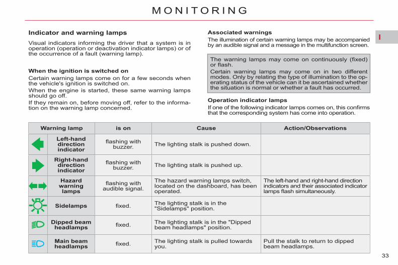
Indicator and warning lamps Visual indicators informing the driver that a system is in operation (operation or deactivation indicator lamps) or of the occurrence of a fault (warning lamp).
When the ignition is switched on Certain warning lamps come on for a few seconds when the vehicle's ignition is switched on. When the engine is started, these same warning lamps should go off. If they remain on, before moving off, refer to the informa-tion on the warning lamp concerned.
Associated warnings The illumination of certain warning lamps may be accompanied by an audible signal and a message in the multifunction screen.
Operation indicator lamps If one of the following indicator lamps comes on, this confi rms that the corresponding system has come into operation.
The warning lamps may come on continuously (fi xed) or fl ash. Certain warning lamps may come on in two different modes. Only by relating the type of illumination to the op-erating status of the vehicle can it be ascertained whether the situation is normal or whether a fault has occurred.
Warning lamp is on Cause Action/Observations
Left-hand direction indicato r
fl ashing with buzzer. The lighting stalk is pushed down.
Right-hand direction indicator
fl ashing with buzzer. The lighting stalk is pushed up.
Sidelamps fi xed. The lighting stalk is in the "Sidelamps" position.
Dipped beam headlamps fi xed. The lighting stalk is in the "Dipped
beam headlamps" position.
Main beam headlamps fi xed. The lighting stalk is pulled towards
you. Pull the stalk to return to dipped beam headlamps.
Hazard warning lamps
fl ashing with audible signal.
The hazard warning lamps switch, located on the dashboard, has been operated.
The left-hand and right-hand direction indicators and their associated indicator lamps fl ash simultaneously.

I
34
M O N I T O R I N G
Warning lamp is on Cause Action/Observations
Front foglamps fi xed. The front foglamps are
switched on. Turn the ring on the stalk rearwards twice to switch off the front foglamps.
Rear foglamps fi xed. The rear foglamps are
switched on. Turn the ring on the stalk rearwards to switch off the rear foglamps.
Diesel engine pre-heating fi xed. The ignition switch is at the
2nd position (ignition on). Wait until the warning lamp has switched off before starting. The duration for which the warning lamp is on is determined by the climatic conditions.
Parking brake
fi xed. The parking brake is applied or not properly released.
Release the parking brake to switch off the warning lamp, keeping your foot on the brake pedal. Observe the safety recommendations. For further information on the parking brake, refer to the "Driving" section.
fl ashing. The parking brake is not fully applied or is released.
Parking space
sensors
fi xed. The parking space sensors function is active.
Press the corresponding button to deactivate it.
fl ashing. The system is measuring the space.
Once the measurement has been done, the warning lamp comes on fi xed again.
Electric child lock temporarily. The electric child lock is
activated.
Displayed for a few seconds after activating the function and every time the ignition is switched on. For more information, refer to the "Child safety" section.

I
35
M O N I T O R I N G
Warning lamp is on Cause Action/Observations
Stop & Start
fi xed. When the vehicle stops (red lights, traffi c jams, ...) the Stop & Start system has put the engine into STOP mode.
The warning lamp goes off and the engine restarts automatically in START mode, as soon as you want to move off.
fl ashes for a few seconds, then
goes off.
STOP mode is temporarily unavailable. or START mode is invoked automatically.
Refer to "Driving - § Stop & Start" for special cases with STOP mode and START mode.
Passenger's
airbag system
fi xed.
The control switch, located in the glove box, is in the " ON " position. The passenger's front airbag is activated. In this case, do not install a rear-facing child seat.
Turn the control switch to the " OFF " position to deactivate the front passenger's airbag. In this case you can install a rear-facing child seat.
I
36
M O N I T O R I N G
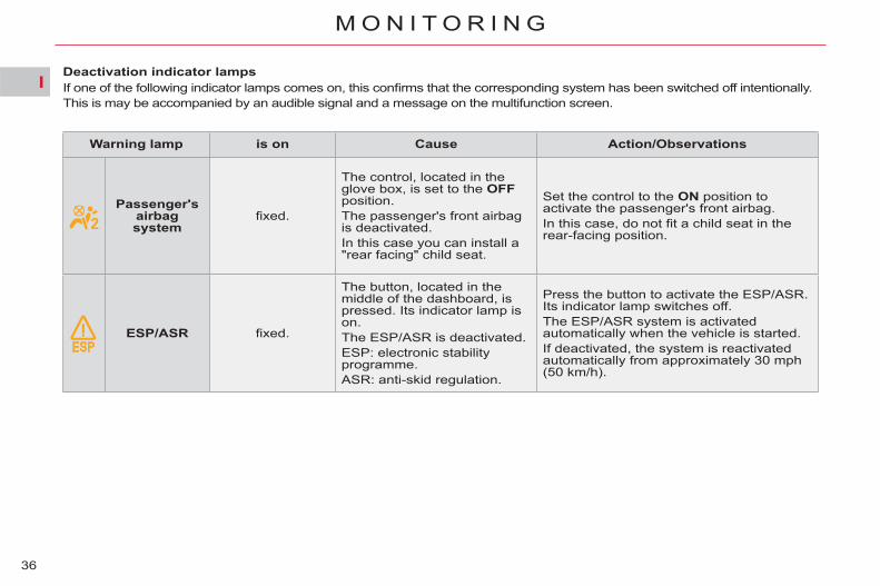
Deactivation indicator lamps If one of the following indicator lamps comes on, this confi rms that the corresponding system has been switched off intentionally. This is may be accompanied by an audible signal and a message on the multifunction screen.
Warning lamp is on Cause Action/Observations
Passenger's
airbag system
fi xed.
The control, located in the glove box, is set to the OFF position. The passenger's front airbag is deactivated. In this case you can install a "rear facing" child seat.
Set the control to the ON position to activate the passenger's front airbag. In this case, do not fi t a child seat in the rear-facing position.
ESP/ASR fi xed.
The button, located in the middle of the dashboard, is pressed. Its indicator lamp is on. The ESP/ASR is deactivated. ESP: electronic stability programme. ASR: anti-skid regulation.
Press the button to activate the ESP/ASR. Its indicator lamp switches off. The ESP/ASR system is activated automatically when the vehicle is started. If deactivated, the system is reactivated automatically from approximately 30 mph (50 km/h).
I
37
M O N I T O R I N G
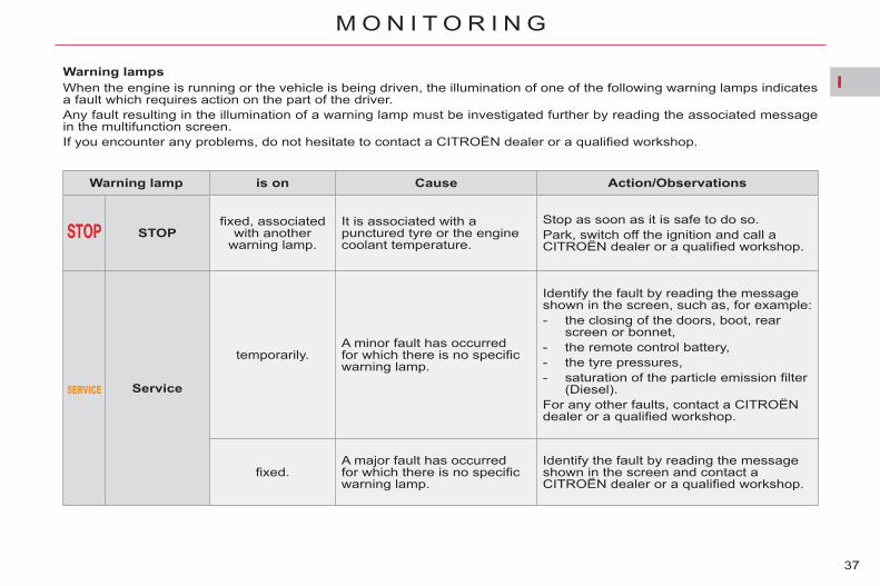
Warning lamps When the engine is running or the vehicle is being driven, the illumination of one of the following warning lamps indicates a fault which requires action on the part of the driver. Any fault resulting in the illumination of a warning lamp must be investigated further by reading the associated message in the multifunction screen. If you encounter any problems, do not hesitate to contact a CITROËN dealer or a qualifi ed workshop.
Warning lamp is on Cause Action/Observations
STOP fi xed, associated
with another warning lamp.
It is associated with a punctured tyre or the engine coolant temperature.
Stop as soon as it is safe to do so. Park, switch off the ignition and call a CITROËN dealer or a qualifi ed workshop.
Service
temporarily. A minor fault has occurred for which there is no specifi c warning lamp.
Identify the fault by reading the message shown in the screen, such as, for example: - the closing of the doors, boot, rear
screen or bonnet, - the remote control battery, - the tyre pressures, - saturation of the particle emission fi lter
(Diesel). For any other faults, contact a CITROËN dealer or a qualifi ed workshop.
fi xed. A major fault has occurred for which there is no specifi c warning lamp.
Identify the fault by reading the message shown in the screen and contact a CITROËN dealer or a qualifi ed workshop.

I
38
M O N I T O R I N G
Warning lamp is on Cause Action/Observations
Anti-lock Braking System (ABS)
fi xed. The anti-lock braking system has a fault.
The vehicle retains conventional braking. Drive carefully at reduced speed and contact a CITROËN dealer or a qualifi ed workshop without delay.
Electric parking brake fl ashing.
The application or release of the electric parking brake was interrupted.
You must stop as soon as it is safe to do so. Park on level ground, switch off the ignition and contact a CITROËN dealer or a qualifi ed workshop.
+
Electric parking brake malfunction
fi xed. The electric parking brake has a fault.
Automatic application/release is no longer possible. Contact a CITROËN dealer or a qualifi ed workshop without delay. The parking brake can be released manually using the emergency release procedure. For more information on the electric parking brake, refer to the "Driving" section.
Braking
fi xed, associated with the STOP warning lamp.
The braking system fl uid level is too low.
You must stop as soon as it is safe to do so. Top up with brake fl uid recommended by CITROËN. If the problem persists, have the system checked by a CITROËN dealer or a qualifi ed workshop.
+ fi xed, associated with the STOP
and ABS warning lamp.
The electronic brake force distribution (EBFD) system has a fault.
You must stop as soon as it is safe to do so. Have it checked by a CITROËN or a qualifi ed workshop.

I
39
M O N I T O R I N G
Deactivation of the automatic
functions of the electric parking
brake
fi xed.
The "automatic application" (on switching off the engine) and "automatic release" functions are deactivated or faulty.
Activate the function (according to country) via the vehicle confi guration menu or contact a CITROËN dealer or a qualifi ed workshop if automatic application/release is not possible. The parking brake can be released manually using the emergency release procedure. For more information on the electric parking brake, refer to the "Driving" section.
Warning lamp is on Cause Action/Observations
Dynamic stability control
(ESP/ASR)
fl ashing. The ESP/ASR regulation is active.
The system optimises traction and improves the directional stability of the vehicle.
fi xed. Unless it has been deactivated (button pressed and its indicator lamp on) the ESP/ASR system has a fault.
Have it checked by a CITROËN or a qualifi ed workshop.
Engine
autodiagnosis system
fl ashing. The engine management system has a fault.
Risk of destruction of the catalytic converter. Have it checked by a CITROËN dealer or a qualifi ed workshop.
fi xed. The emission control system has a fault.
The warning lamp should go off when the engine is started. If it does not go off, contact a CITROËN dealer or qualifi ed workshop without delay.
Airbags
temporarily. This lamp comes on for a few seconds when you turn on the ignition, then goes off.
This lamp should go off when the engine is started. If it does not go off, contact a CITROËN dealer or a qualifi ed workshop.
fi xed. One of the airbag or seat belt pretensioner systems has a fault.
Have it checked by a CITROËN dealer or a qualifi ed workshop.

I
40
M O N I T O R I N G
Warning lamp is on Cause Action/Observations
Low fuel level
fi xed, accompanied by an audible signal and a
message on the multifunction
screen.
When it fi rst comes on there remains approximately7 litres of fuel in the tank.
You must refuel as soon as possible to avoid running out of fuel. This warning lamp will come on every time the ignition is switched on, until suffi cient fuel has been added. Fuel tank capacity: 60 litres. Never continue to drive until you run out of fuel, this could damage the emission control and injection systems.
Foot on the brake pedal
fi xed. The brake pedal is not pressed.
With the 6-speed electronic gearbox system, you must press the brake pedal to start the engine (lever in position N ).
fl ashing.
The brake pedal is not pressed.
With the automatic gearbox, with the engine running (lever in position P ), press the brake pedal before releasing the parking brake, to unlock the lever and come out of position P . If you wish to release the parking brake without pressing the brake pedal, this warning lamp will remain on.
With the electronic gearbox system, if you hold the vehicle on an incline using the accelerator for too long, the clutch overheats.
Use the brake pedal and/or the electric parking brake.

I
41
M O N I T O R I N G
Warning lamp is on Cause Action/Observations
Maximum coolant
temperature fi xed red. The temperature of the
cooling system is too high.
Stop as soon as it is safe to do so. Wait until the engine has cooled down before topping up the level, if necessary. If the problem persists, contact a CITROËN dealer or qualifi ed workshop.
Battery charge fi xed.
The battery charging circuit has a fault (dirty or loose terminals, slack or cut alternator belt, ...).
The warning lamp should go off when the engine is started. If it does not go off, contact a CITROËN dealer or a qualifi ed workshop.
Door(s) open
fi xed if the speed is below 6 mph
(10 km/h).
A door, the boot or the rear screen is still open. Close the door or boot. fi xed and
accompanied by an audible signal
if the speed is above 6 mph
(10 km/h).
Seat belts
not fastened/unfastened
fi xed. The driver and/or the front/rear passenger has not fastened or has unfastened their seat belt.
Pull the strap then insert the tongue in the buckle. The illuminated dots represent the passengers that have not fastened/unfastened their seat belt. They come on: - fi xed for 30 about seconds on starting
the vehicle, - fi xed from 0 to 12 mph (0 to 20 km/h)
when driving, - fl ashing above 12 mph (20 km/h),
accompanied by an audible signal for about 120 seconds.

I
42
M O N I T O R I N G
Service indicator System which informs the driver when the next service is due, in ac-cordance with the manufacturer's servicing schedule. The point at which the service is due is calculated from the last indicator zero reset. It is determined by two parameters: - the distance travelled, - the time elapsed since the last
service.
5 seconds after the ignition is switched on, the spanner goes off ; the dis-tance recorder resumes its normal operation. The display then indicates the total and trip distances.
Less than 1 000 km remain before the next service is due Example: 900 km remain before the next service is due. For 5 seconds after the ignition is switched on, the display indicates:
Service overdue For 5 seconds after the ignition is switched on, the spanner fl ashes to indicate that the service must be carried out as soon as possible. Example: the service is overdue by 300 km. For 5 seconds after the ignition is switched on, the display indicates:
5 seconds after the ignition is switched on, the distance recorder resumes its normal operation. The spanner remains on to indicate that a service must be carried out soon.
5 seconds after the ignition is switched on, the distance recorder resumes its normal operation. The spanner re-mains on .
More than 1 000 km remain before the next service is due For 5 seconds after the ignition is switched on, the spanner symbol-ising the service operations comes on. The distance recorder display line indicates the distance remaining before the next service is due. Example: 4 800 km remain before the next service is due. For 5 seconds after the ignition is switched on, the display indicates:
The distance remaining may be weighted by the time factor, depend-ing on the driver's driving habits. Therefore, the spanner may also come on if you have exceeded the two year service interval.

I
43
M O N I T O R I N G
Service indicator zero reset Engine oil level indicator
After each service, the service indi-cator must be reset to zero. The procedure for resetting to zero is as follows: switch off the ignition, press and hold the trip distance
recorder zero reset button, switch on the ignition; the dis-
tance recorder display begins a countdown,
when the display indicates "=0" , release the button; the spanner disappears.
System which informs the driver whether the engine oil level is cor-rect or not. This information is displayed for a few seconds when the ignition is switched on, after the service infor-mation. The level read will only be correct if the vehicle is on level ground and the engine has been off for more than 30 minutes.
Oil level correct
Oil level low
This is indicated by the fl ashing of "OIL" , accompanied by an audible signal and a message on the multi-function screen. If the low oil level is confi rmed by a check using the dipstick, it is essen-tial that the level is topped up to pre-vent damage to the engine.
Oil level gauge fault
This is indicated by the fl ashing of "OIL--" . Contact a CITROËN dealer or a qualifi ed workshop.
Dipstick Refer to the "Checks" section to lo-cate the dipstick and the oil fi ller cap on your engine.
There are 2 marks on the dipstick: - A = max; never ex-
ceed this level (risk of engine damage),
- B = min; top up the level via the oil fi ller, using the type of oil suited to your en-gine.
Following this operation, if you wish to disconnect the battery, lock the vehicle and wait at least fi ve minutes for the zero reset to be taken into ac-count.
I
44
M O N I T O R I N G
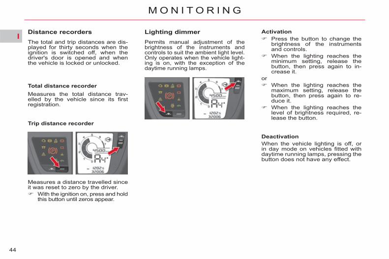
Distance recorders The total and trip distances are dis-played for thirty seconds when the ignition is switched off, when the driver's door is opened and when the vehicle is locked or unlocked.
Measures the total distance trav-elled by the vehicle since its fi rst registration.
Trip distance recorder
Lighting dimmer Permits manual adjustment of the brightness of the instruments and controls to suit the ambient light level. Only operates when the vehicle light-ing is on, with the exception of the daytime running lamps.
Activation Press the button to change the
brightness of the instruments and controls.
When the lighting reaches the minimum setting, release the button, then press again to in-crease it.
or When the lighting reaches the
maximum setting, release the button, then press again to re-duce it.
When the lighting reaches the level of brightness required, re-lease the button.
Deactivation When the vehicle lighting is off, or in day mode on vehicles fi tted with daytime running lamps, pressing the button does not have any effect.
Total distance recorder
Measures a distance travelled since it was reset to zero by the driver. With the ignition on, press and hold
this button until zeros appear.

II
45
M U L T I F U N C T I O N S C R E E N S
MONOCHROME SCREEN A
Displays in the screen
This screen can display the following information: - time - date - ambient temperature When the ambient temperature
is between +3 °C and -3 °C, the temperature display fl ashes (risk of ice). The ambient temperature displayed may be higher than the actual temperature if the ve-hicle is parked in the sun.
- the current audio source, - trip computer (see the end of the
section). Alert messages (e.g.: "Antipollution system faulty") or information mes-sages (e.g.: "Boot open") may appear temporarily. They can be removed by pressing "ESC" .
A. Access to the "Main menu". B. Navigation in the screen menus. C. Confi rmation of the selection of a
function in a menu or of a value modifi ed.
D. Cancellation the current operation. E. Selection of the type of infor-
mation (date, audio-CD and trip computer).
B or F. In the menus, navigation, choice of activation/deactiva-tion of functions and choice of settings.
Press button A , then using B , you have access to the following menus: - radio-CD - vehicle confi g - options - display adjust - languages - units
Press button C to confi rm.
Controls Main Menu
For safety reasons, confi guration of the multifunction screen by the driver must only be done when stationary.
II
46
M U L T I F U N C T I O N S C R E E N S
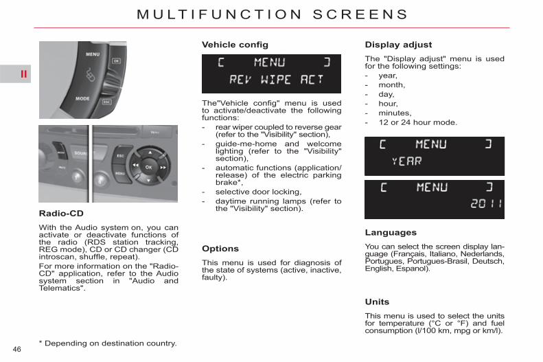
Vehicle config
Options This menu is used for diagnosis of the state of systems (active, inactive, faulty).
Radio-CD With the Audio system on, you can activate or deactivate functions of the radio (RDS station tracking, REG mode), CD or CD changer (CD introscan, shuffl e, repeat). For more information on the "Radio-CD" application, refer to the Audio system section in "Audio and Telematics".
Display adjust The "Display adjust" menu is used for the following settings: - year, - month, - day, - hour, - minutes, - 12 or 24 hour mode.
Languages You can select the screen display lan-guage (Français, Italiano, Nederlands, Portugues, Portugues-Brasil, Deutsch, English, Espanol).
Units This menu is used to select the units for temperature (°C or °F) and fuel consumption (l/100 km, mpg or km/l).
* Depending on destination country.
The"Vehicle confi g" menu is used to activate/deactivate the following functions: - rear wiper coupled to reverse gear
(refer to the "Visibility" section), - guide-me-home and welcome
lighting (refer to the "Visibility" section),
- automatic functions (application/release) of the electric parking brake * ,
- selective door locking, - daytime running lamps (refer to
the "Visibility" section).

II
47
M U L T I F U N C T I O N S C R E E N S
MONOCHROME SCREEN C Main Menu Displays in the screen
Controls
This screen can display the following information: - time - date, - ambient temperature When the ambient temperature
is between +3 °C and -3 °C, the temperature display fl ashes (risk of ice). The ambient temperature displayed may be higher than the actual temperature if the vehicle is parked in the sun.
- the current audio source - trip computer (see the end of the
section), - the results of the parking space
measurement, - visual parking sensors. Alert messages (e.g.: "Antipollution system faulty") or information mes-sages (e.g.: "Boot open") may appear temporarily. They can be removed by pressing "ESC" .
For safety reasons, confi guration of the multifunction screen by the driver must only be done when stationary.
A. Access to the "Main Menu". B. Navigation in the screen menus. C. Selection and confi rmation in the
menus of the function chosen or the value modifi ed.
D. Cancellation of the current opera-tion.
E. Selection of the type of information (date, radio-CD/audio, telephone and trip computer).
B or F. In the menus, navigation, choice of activation/deactiva-tion of functions and choice of settings.
Press button A , then using B , you have access to the following menu: - audio functions, - trip computer, - personalisation-confi guration, - Bluetooth telephone (hands-free
system). Press button C to confi rm.

II
48
M U L T I F U N C T I O N S C R E E N S
Warning log This lists alert messages, displaying them successively on the multifunc-tion screen.
Audio functions
Trip computer
Bluetooth telephone (hands-free system)
You can see information on the state of the vehicle.
With the Audio system on, you can activate or deactivate functions as-sociated with the radio (RDS, REG, Radio Text), CD or CD changer (CD introscan, shuffl e, repeat). For more information on the "Audio functions" application, refer to the Audio system section in "Audio and Telematics".
With the Audio system on, you can confi gure your Bluetooth hands-free system (pairing), view the various telephone directories (calls log, ser-vices..) and manage calls (call, hang up, double call, secret mode...). For more information on the "Telephone" application, refer to the Audio system section in "Audio and Telematics".
Status of functions This allows diagnosis of the state of systems (active, inactive, faulty).
Enter the distance to destination You can enter a value for the dis-tance to your fi nal destination.

II
49
M U L T I F U N C T I O N S C R E E N S
Choice of language You can change the screen display language (Deutsch, English, Espanol, Français, Italiano, Nederlands, Portugues, Portugues-Brasil, Türkçe * ).
* Depending on destination country.
This menu is used to activate/deac-tivate the following functions: - defi ne the vehicle parameters, - display confi guration, - choice of language.
Defi ne the vehicle parameters You can activate or deactivate the following systems: - rear wiper coupled with reverse
gear (refer to the "Visibilty" section), - automatic guide-me-home lighting, - directional headlamps, - automatic functions (application/
release) of the electric parking brake *
- selective door locking, - daytime running lamps (refer to
the "Visibilty" section),
Display confi guration You can make the following adjust-ments: - video brightness, - date and time, - choice of units.
Personalisation - Configuration

II
50
M U L T I F U N C T I O N S C R E E N S
MyWay MULTIFUNCTIONSCREEN
This screen can display the following information: - time, - date, - ambient temperature When the ambient temperature
is between +3 °C and -3 °C, the display fl ashes (risk of ice). The temperature displayed may be higher that the actual tem-perature if the vehicle has been parked in the sun.
- warning and vehicle function status messages, displayed temporarily,
- audio functions, - trip computer (see the end of the
section), - result of the parking space mea-
surement, - visual parking sensor information, - satellite navigation system infor-
mation.
Controls
Displays in the screen
For safety reasons, confi guration of the multifunction screen by the driver must only be done when stationary.
You can press: A. Opens a contextual menu. B. Navigation through the screen
menus. C. Confi rmation of the selection made
in a menu or a modifi ed value. D. Abandon the current operation. E. Selection of main display (date,
radio-CD/audio, telephone, map, navigation and trip computer).
B or F. In the menus, navigation, se-lect activation/deactivation of functions and select settings.
To select one of the applications: press the dedicated "RADIO" ,
"MUSIC" , "NAV" , "TRAFFIC" , "SETUP" or "PHONE" button to open the corresponding menu,
For more information on these ap-plications, refer to the "Audio and Telematics" section.
Menus in the control panel

II
51
M U L T I F U N C T I O N S C R E E N S
SETUP menu
Press the "SETUP" button to open the confi guration menu. This allows you to select from the following functions: - "System language", - "Date and time", - "Display", - "Vehicle", - "Units", - "System".
System language This menu allows you to select the language used by the dis-play: Deutsch, English, Espanol, Français, Italiano, Nederlands, Polski, Portugues, Türkçe * .
* According to country.
Date and time This menu allows you to set the date and time, the format of the date and the format of the time (refer to the "Audio and Telematics" section.
Display This menu allows you to set the brightness of the screen, the screen colour scheme and the colour of the map (day/night or auto mode).
Vehicle This menu allows you to activate or deactivate certain driving and comfort equipment: - wiper linked with reverse gear
(refer to the "Visibility" section), - guide-me-home lighting (refer to
the "Visibility" section), - directional headlamp lighting (refer
to the "Visibility" section), - interior mood lighting (refer to
the "Visibility" section), - electric parking brake automatic
functions (automatic application/release) * ,
- selective door locking, - daytime running lamps (refer to
the "Visibility" section),
Units This menu allows you to select the units: temperature (°C or °F) and consumption (km/l, l/100 or mpg).
System This menu allows you to restore the factory confi guration, display the soft-ware version and activate scrolling text.

II
52
M U L T I F U N C T I O N S C R E E N S
NAVIDRIVE MULTIFUNCTION SCREEN
Displays in the screen
The screen can display the following information: - time - date - ambient temperature When the ambient temperature
is between +3 °C and -3 °C, the temperature display fl ashes (risk of ice). The ambient temperature displayed may be higher than the actual temperature if the ve-hicle is parked in the sun.
- alert messages and state of ve-hicle systems, displayed tempo-rarily.
For safety reasons, confi guration of the multifunction screen by the driver must only be done when stationary.
Controls
A. Access to the "Main Menu". B. Navigation in the screen menus. C. Selection and confi rmation in the
menus of the function chosen or the value modifi ed.
D. Cancellation of the current op-eration or return to the previous display.
E. Selection of the principal dis-play (date, radio-CD/audio, tele-phone, map, navigation and trip computer).
B or F. In the menus, navigation, choice of activation/deactiva-tion of functions and choice of setting.
- audio functions, - trip computer (see end of the
section), - results of the parking space
measurement, - visual parking sensors, - satellite navigation system infor-
mation.
II
53
M U L T I F U N C T I O N S C R E E N S
Main Menu
Traffi c Information
Navigation/Guidance
Map
Audio Functions
Telematics
Confi guration, to confi gure the screen (date, time...) and defi ne vehicle parameters
Video
Vehicle Diagnostics - "Alert log", - "Status of functions".
Press button A to display the "Main Menu":
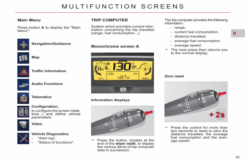
TRIP COMPUTER System which provides current infor-mation concerning the trip travelled (range, fuel consumption...).
Monochrome screen A
Information displays
Press the control for more than two seconds to reset to zero the distance travelled, the average fuel consumption and the aver-age speed.
Zero reset
The trip computer provides the following information:
- range, - current fuel consumption, - distance travelled, - average fuel consumption, - average speed.
The next press then returns you to the normal display.
Press the button, located at the end of the wiper stalk , to display the various items of trip computer data in succession.

II
54
M U L T I F U N C T I O N S C R E E N S
TRIP COMPUTER System which provides current infor-mation concerning the route travelled (range, fuel consumption, …) in the multifunction screen.
Monochrome screen C
MyWay or NaviDrive colour screen
Display of information
Trip zero reset Press the button, located at the end of the wiper stalk , to display the various trip computer infor-mation groups in succession:
- the current information group with: ● range, ● current fuel consump-
tion, ● distance remaining to
be travelled/Stop & Start time counter,
- the trip "1" group with: ● distance travelled, ● average fuel con-
sumption, ● average speed, for the fi rst trip.
- the trip "2" group with: ● the distance travelled, ● the average fuel con-
sumption, ● the average speed, for the second trip.
When the trip required is dis-played, press the control for more than two seconds.
Trips "1" and "2" are independent but their use is identical. For example, trip "1" can be used for daily fi gures and trip "2" for monthly fi gures.

II
55
M U L T I F U N C T I O N S C R E E N S
A few definitions…
Range (miles or km)
This value may vary following a change in the style of driving or the relief, resulting in a signifi cant change in the current fuel con-sumption.
When the range falls below 20 miles (30 km), dashes are displayed. After fi lling with at least 5 litres of fuel, the range is recalculated and is dis-played when it exceeds 60 miles (100 km).
If dashes are displayed continu-ously while driving in place of the digits, contact a CITROËN dealer or a qualifi ed workshop.
This indicates the distance which can still be travelled with the fuel re-maining in the tank in relation to the average fuel consumption over the last few miles (kilometres) travelled.
Current fuel consumption (mpg or l/100 km or km/l)
Average fuel consumption (mpg or l/100 km or km/l) This is the average fuel
consumption since the last trip com-puter zero reset.
Average speed (mph or km/h)
This is the average speed calculated since the last trip computer zero reset (ignition on).
Distance travelled (miles or km)
This indicates the distance travelled since the last trip computer zero reset.
Distance remaining to destination (miles or km)
This is the distance remaining to be travelled to the fi nal destination. It is either calculated instantly by the navigation system, if guidance is ac-tivated, or entered by the user. If the distance is not entered, dashes are displayed in place of the digits.
This function is only displayed from 20 mph (30 km/h).
This is the average fuel consump-tion during the last few seconds.
If your vehicle is fi tted with Stop & Start, a time counter calculates the time spent in STOP mode during a journey. It resets to zero every time the igni-tion is switched on with the key.
Stop & Start time counter (minutes/seconds or hours/minutes)

III
56
C O M F O R T
RECOMMENDED SETTINGS FOR VENTILATION, HEATING ANDAIR CONDITIONING
Air intake Check that the exterior grille for the air intake at the bottom of the wind-screen, is clean and free of dead leaves, snow, etc.
Air distribution 1. Windscreen demisting/defrosting
vents. 2. Front quarter light window demi-
sting/defrosting vents. 3. Front side window demisting/
defrosting vents. Adjustable side air vents. 4. Adjustable central air vents. 5. Front passenger footwell air out-
lets. 6. Adjustable 2nd row side air
vents, with air fl ow and tempera-ture adjustment.
7. Rear passenger footwell air out-lets.
8. Adjustable 3rd row side air vents.
The side air vents 8 apply only to the 7-seater versions.

III
57
C O M F O R T
Air conditioning To ensure that your system operates correctly, it is recommended that you have it checked regularly. Water arising from condensation in the air conditioning drains away through a hole provided for this pur-pose. A pool of water may thus form under the vehicle when stationary. To preserve the sealing of the air conditioning compressor, operate the air conditioning at least once a month. Regardless of the season, the air conditioning is useful, since it re-moves humidity and condensation. To be effective, the air conditioning should only be used with the win-dows closed. If after a lengthy stop in bright sunlight the interior temperature is excessive, air the passenger compartment by opening the windows for a few mo-ments, then close them again. The air conditioning operates by using power from the engine. This results in a slight increase in fuel consumption.
Dust filter/Odour filter (active carbon) There is a fi lter for excluding odours and dust. This fi lter has to be changed in ac-cordance with the vehicle's servicing schedule (see the servicing booklet).
Air circulation Air vents on the fl oor underneath the front seats provide enhanced heat-ing for the rear seat positions; take care not to obstruct them.
Air vents The air vents to the face have grilles and thumb wheels to adjust the air fl ow and direction (up-down, right-left).
The automatic regulation of the air conditioning in the passenger com-partment uses a number of sensors (sunshine sensor, ambient tempera-ture sensor...) that relieve you of the need to make frequent adjustments to the displayed temperature. Take care not to obstruct the sun-shine sensor, located on the dash-board behind the instrument panel.
Sensors

III
58
C O M F O R T
MANUAL AIR CONDITIONING The air conditioning system oper-ates with the engine running.
A. DRIVER'S CONTROL PANEL
1. Adjustment of the air fan speed
The air fan adjustment only operates when the engine is running. To adjust the air fl ow, press button 1 :
to increase the fl ow of air,
to decrease the fl ow of air.
The level of air fl ow is shown by the progressive lighting of the warning lamps depicting the fan blades 1 . By reducing the fl ow to minimum, you deactivate the air conditioning system (OFF). To maintain an acceptable level of comfort in the passenger compart-ment, you should not leave this con-trol too long in the OFF position.
2. Adjustment of air distribution
Press button 2 to make the dis-play run through the different types of air distribution.
The air distribution chosen is shown by the lighting of the corresponding warning lamps on the display 2 .
3. Mode of adjustment of temperature for the passenger
Press button 3 to have indepen-dent passenger control of cabin air temperature. The warning lamp goes off.
While the passenger is adjusting tem-perature, the warning lamp comes on.
4. Air recirculation This control is for isolating disagree-able odours or fumes coming from outside. Press button 4 to cut off the intake
of outside air and to activate recir-culation of the air in the passenger compartment. The warning lamp comes on.
Avoid the extended use of air re-circulation (risk of deterioration of air quality and misting).
Press button 4 again to allow the intake of exterior air. The warning lamp goes off.
5. Air conditioning The air fan control (adjusting the fl ow of air) has to be activated in order for air conditioning to be obtained. Press button 5 . The warning
lamp comes on. To be effective, the air condi-
tioning should be operated only with the windows closed.
If your vehicle is not equipped with air conditioning, you will have the same control panel but without the A/C button.
III
59
C O M F O R T
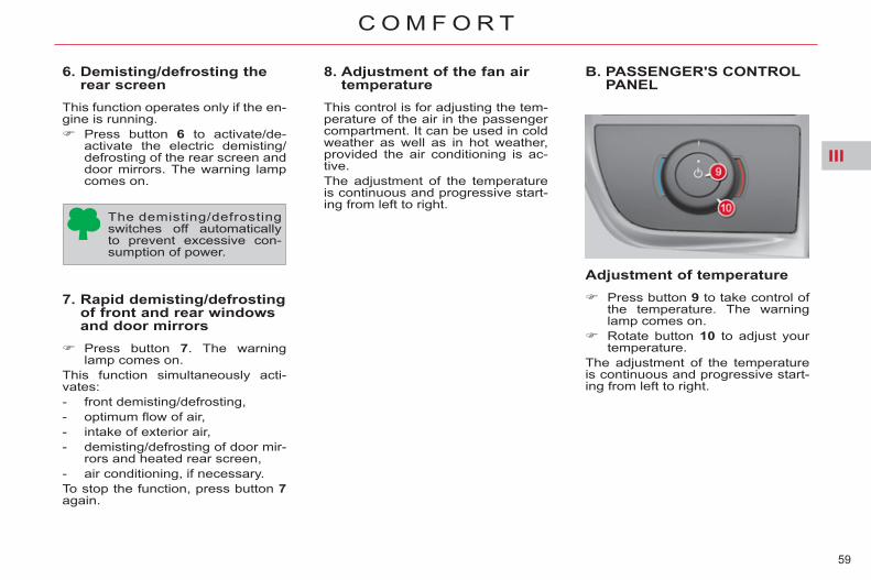
6. Demisting/defrosting the rear screen
This function operates only if the en-gine is running. Press button 6 to activate/de-
activate the electric demisting/defrosting of the rear screen and door mirrors. The warning lamp comes on.
7. Rapid demisting/defrosting of front and rear windows and door mirrors
Press button 7 . The warning lamp comes on.
This function simultaneously acti-vates: - front demisting/defrosting, - optimum fl ow of air, - intake of exterior air, - demisting/defrosting of door mir-
rors and heated rear screen, - air conditioning, if necessary. To stop the function, press button 7 again.
8. Adjustment of the fan air temperature
This control is for adjusting the tem-perature of the air in the passenger compartment. It can be used in cold weather as well as in hot weather, provided the air conditioning is ac-tive. The adjustment of the temperature is continuous and progressive start-ing from left to right.
Adjustment of temperature Press button 9 to take control of
the temperature. The warning lamp comes on.
Rotate button 10 to adjust your temperature.
The adjustment of the temperature is continuous and progressive start-ing from left to right.
The demisting/defrosting switches off automatically to prevent excessive con-sumption of power.
B. PASSENGER'S CONTROL PANEL

III
60
C O M F O R T
DIGITAL AIR CONDITIONING
The air conditioning system operates with the engine running.
1. Automatic comfort regulation
A press on this button,confi rmed by the display of the A/C warning lamp and of AUTO on the screen, pro-
vides automatic control, at the tem-perature selected, of all the following 5 functions: - air fl ow, - passenger compartment tem-
perature, left and right, - air distribution, - air conditioning, - automatic air recirculation.
For this facility to operate, it is recom-mended that all air vents are kept open. Using the AUTO mode will prevent the formation of mist inside the ve-hicle in cold or humid weather. When starting from cold, in order to avoid a rush of cold air, the air fan attains its optimum level progres-sively.
2. Adjustment of temperature To display the desired temperature, press button: - - to decrease the temperature, - + to increase the temperature. A setting around 21 will provide an agreeable temperature level. However, depending on your prefer-ence, anything between 18 and 24 is quite normal. For optimum comfort, it is recom-mended to avoid a difference of set-tings of more than than 3 between right and left. Actual temperatures experienced in the passenger compartment are de-pendent on external factors and for this reason might not be identical to those displayed. On entering the vehicle, the inside temperature may be much colder (or hotter) than would be comfortable. It serves no purpose to alter the tem-perature displayed in an attempt to attain your preference more rapidly. The system operates automatically to correct the difference in tempera-ture as soon as possible.
Manual resumption of one or more functions It is possible to adjust each of the functions 3, 4 , 6 and 10 manually. The display of the "AUTO" function will then go off.
Resumption by the driver of the adjustment of passenger compart-ment temperatures (for the front and rear passengers) A long press on the "AUTO" but-ton cancels all personal settings, including the passenger's tem-perature, and returns the system to automatic operation
A. DRIVER'S CONTROL PANEL

III
61
C O M F O R T
3. Adjustment of air fan speed/Activation of the "REST" function
to increase the air fl ow,
to decrease the air fl ow (this button also has the REST function).
The level of air fl ow is indicated on the display by the progressive fi lling of the fan blades. If you place the air fan on position 0 , the system is deactivated. The air fan display will be empty, with the in-dication OFF.
To allow a degree of comfort in the passenger compart-ment while the engine is off, you can operate the ven-
tilation for a few minutes using the "REST" function. When you leave the vehicle, any passengers present can still have the benefi t of air circulation, even though the engine is not running.
This function is available when you switch on the ignition as well as when you stop the engine. The air conditioning control screens come on and the symbol represent-ing the air fan is displayed while the function is available.
This button does not activate the air conditioning, only the air fans. While the REST function is active, the air fl ow and distribution cannot be modi-fi ed.
On switching on the ignition: - A press on the REST button ac-
tivates the function for a period of a few minutes. Two blades of the fan will fi ll to indicate that the function is active.
- The function can be deactivated and reactivated during the timed period.
- At the end of the timed period, the screen will go off.
4. Adjustment of air distribution
Press button 4 to scroll through the air distribution settings on the screen.
Adjustment of air fl ow To adjust the fl ow of air, press the button:
"REST" function: activation of ventilation, engine off
On switching off the engine: - The function can be activated
during a period of 30 seconds. - A press on the REST button ac-
tivates the function for period of several minutes. The duration and availability of the function depends on the state of charge of the battery. Locking the vehi-cle has no effect on the function.
- A further press before the end of the period of operation stops the function defi nitively.
The air distribution you have chosen is confi rmed by the corresponding indicators in the screen. There are 7 possible adjustments.

III
62
C O M F O R T
5. Air recirculation
Press button 5 to cut off the in-take of air from outside and to activate recycling of the air in the passenger compartment. the warning lamp comes on.
Whilst retaining the other adjust-ments, this function prevents un-pleasant odours or fumes entering the vehicle. Avoid extended use of air recirculation (risk of deterioration of air quality and misting). Press button 5 again to allow entry
of air from the outside. The warn-ing lamp goes off.
Air recirculation can also be controlled by pressing the switch located on the lower left of the steering wheel (see "Fixed centred controls steering wheel").
6. Activation/deactivation of rear passenger controls
This button allows you to permit or not the rear pas-sengers to use their adjust-ment controls.
There are three possible states for this button:
Locking of the rear passenger controls
Authorisation of the rear passenger controls
Reduction of the air fl ow for the rear passengers
With additional air conditioning, in cold weather you are advised to close the supply of air to the rear passengers (no hot air distribution possible via these air vents).
The rear passengers can use their adjustment controls at their conve-nience.
The driver imposes his adjustment on the rear passengers. In this case, the rear passenger controls are de-activated.
7. Panel display mode: black panel function
This function turns the screen and switch backlight-ing on or off.
- Function activated, pressing any button will illuminate the screen temporarily.
- pressing button 7 deactivates the function, the illumination of of buttons and screen is again permanent.
This function optimises notably the visual comfort for driving at night.
8. Demisting/defrosting the rear screen
This function is active only when the engine is running. Press on button 8 to activate/
deactivate the electric demist-ing/defrosting of the rear screen and, according to version, of the door mirrors. The warning lamp comes on and the symbol ap-pears in the screen.
It switches off automatically to prevent excessive con-sumption of power.
This button activates the recir-culation of air within the pas-senger compartment and also has an automatic function.

III
63
C O M F O R T
9. Rapid demisting/defrosting of the front and rear windows
- Press button 9 . The warning lamp comes on.
This function gives a rapid demisting/defrosting of the vehicle simultaneously with:
- front demisting/defrosting at op-timum temperature,
- optimum air fl ow, - intake of exterior air, - demisting/defrosting of the door
mirrors and rear screen, - air conditioning, if necessary. Press button 9 again or " AUTO" to stop the function. Demisting/defrosting of the door mirrors and rear screen remains activated.
10. Air conditioning Press button 10 to activate the
air conditioning. The A/C warning lamp comes on.
B. PASSENGER CONTROL PANELS
11. Front passenger The front passenger can adjust their temperature control independently at any time by pressing buttons + and - .
The front passenger con-trols the adjustment of their own temperature.
The temperature setting for the passenger is aligned with that for the driver.
12. Rear passengers (right/left)
By default, in AUTO position, the adjust-ment of the air fl ow is aligned on the front ventilation. Rotate the button
to decrease or in-crease the air fl ow.
You can adjust the air fl ow only if this is enabled by the driver (see button 6 of the driver’s control panel).
With Stop & Start, when demist-ing has been activated, the STOP mode is not available.

III
64
C O M F O R T
ADDITIONAL AIRCONDITIONING
Additional air conditioning allows you to optimise comfort levels in warm weather conditions. It produces ad-ditional fresh air which is supplied using the rear air vents. The supply of warm air via the rear air vents is not possible using this system.
C. REAR PASSENGERCONTROL PANELS (RIGHT/LEFT)
13. Adjustment of temperature
The rear passengers can adjust their temperature controls independently via buttons + and - . Their setting cannot be greater than that of the driver by more than 2. Attainment of this maximum setting is confi rmed by the fl ashing of its display.
14. Adjustment of air fan speed
The air fan operates only when the engine is running. To adjust the fl ow of air, press on button:
to increase the air fl ow,
to decrease the air fl ow.
The level of air fl ow is indicated on the display by the progressive fi lling of the fan blades. By reducing the fl ow to minimum, you switch off the air conditioning system (OFF). You can adjust the temperature and the air fl ow only if the driver enables you to (see button 6 of the driver’s control panel).
This warning lamp signifi es that the passenger controls are locked, you can adjust neither the temperature nor
the air fl ow, which remain aligned on the preferences of the driver.
This warning lamp indi-cates that the supply of air is cut off .
This position is recommended in cold weather conditions, as the air vents do not supply warm air.

III
65
C O M F O R T
SCENTED AIR FRESHENER
The scented air freshener releases a fragrance into the passenger compart-ment via the central air vents.
Rotate the button A to adjust (to the left to reduce, to the right to increase) or stop (maximum to the left) the fl ow of scented air.
The central air vents have to be open.
Press the button A , rotating it a quarter turn to the left as far as it will go.
Remove the air freshener from the dashboard.
Replace the cartridge (see "Replacing a cartridge”).
After fi tting or changing a cartridge: place the air freshener back in its
housing. rotate it a quarter turn to the right.
Adjustment of flow
To remove the air freshener To insert the air freshener
The air freshener contains an empty cartridge when your vehicle is delivered. You therefore need to insert a cartridge in order to use the air freshener.
A cartridge lasts on average 3 months, based on one hour’s usage per day.

III
66
C O M F O R T
The recharge for the air freshener consists of a cartridge B and its sealed container C . Remove the protective fi lm D . Place the head of the cartridge B
on the button A of the air fresh-ener.
Rotate it a quarter turn to lock it on the button and remove the container.
Insert the air freshener into its housing.
You can change cartridges at any time, keeping the used cartridges in their original containers.
The air freshener button A is inde-pendent of the cartridge. Cartridges are supplied without the air freshener button A . The button of the air freshener A can only be fi tted to the centre of the dashboard with a cartridge at-tached. Therefore always keep the air fresh-ener button A and one cartridge. Replacement cartridges are avail-able, depending on country, either on the Internet site or from a CITROËN dealer or a qualifi ed workshop. Locations are provided in the glove box for storing cartridges and con-tainers.
Replacing a cartridge Air freshener button For safety, use only cartridges that are provided for this purpose. Retain the containers for storing used cartridges. Do not recharge or dismantle the cartridges. Keep them out of reach of children and animals. Avoid all contact with the skin and with the eyes. In the event of ingestion, consult a doctor and show them the product packaging or label. Do not install or remove a cartridge while you are driving.

III
67
C O M F O R T
FRONT SEATS
MANUAL ADJUSTMENTS 1. Forwards-backwards
adjustment Raise the control bar, then slide the seat to the position desired.
2. Lumbar support Rotate the control until you attain the position desired.
3. Seat height adjustment Raise or lower the the control the number of times necessary to obtain the position desired. 4. Backrest angle Operate the control and adjust the angle of the backrest. It is possible to incline the back-rest 45° rearwards by tilting it until it locks; to unlock it, lift the control.
5. Armrest To adjust the position of the armrest, pull it up and then fully down, and then raise it to the desired position.
6. Head restraint To raise it, pull it upwards. To lower it, press on the control as well as on the head restraint. The adjustment is correct when the top of the head restraint is level with the top of the head. It can also be adjusted for tilt (de-pending on version). To remove it, press on the unlocking button and pull it upwards. To adjust the head restraint for-wards/backwards, move the base of the head restraint to obtain the posi-tion desired.
Never drive without the head re-straints fi tted. They must be in place and adjusted correctly.

III
68
C O M F O R T
FRONT SEATS
1. Adjustment of the seat height and angle, forwards-backwards
2. Adjustment of backrest angle and lumbar support
The seats can also be adjusted elec-trically for a short period: - on opening one of the front
doors, - after switching off the ignition.
Heated seats control
ELECTRIC ADJUSTMENTS
Raise or lower the front of control to raise or lower the front of the seat base (on driver’s seat).
Raise or lower the rear of control to raise or lower the seat.
Action control forwards or backwards to slide the seat forwards/backwards.
Push the top of control forwards or backwards to adjust the backrest angle.
Raise or lower control to increase or decrease the lumbar support.
With the engine running, the front seats can be heated individually. Use the corresponding adjust-
ment wheel, placed on the inner side of each front seat, to switch on and select the level of heating required:
0 : Off. 1 : Low. 2 : Medium. 3 : High.

III
69
C O M F O R T
Storing driving positions System which registers the electrical settings of the driver's seat and door mirrors. It enables you to store and recall two positions using the but-tons on the side of the driver's seat.
Storing a position
Using buttons M/1/2 Switch on the ignition. Adjust your seat and the door
mirrors. Press button M , then press but-
ton 1 or 2 within four seconds. An audible signal indicates that
the position has been stored. Storing a new position cancels the previous position.
Recalling a stored position
Ignition on or engine running Press button 1 or 2 to recall the
corresponding position. An audible signal indicates the end of the adjustment. You can interrupt the current move-ment by pressing button M , 1 or 2 or by using one of the seat controls. A stored position cannot be recalled while driving. Recalling stored positions is deacti-vated 45 seconds after switching off the ignition.

III
70
C O M F O R T
REAR HEAD RESTRAINTS
The rear head restraints can beremoved and have two positions: - high, position for use, - low, storage position. To raise a head restraint, pull it up-wards. To lower it, press the lug then the head restraint. To remove it, place it in the high posi-tion, push the lug and pull it upwards. To refi t it, engage the head restraint rods in the holes taking care to re-main in line with the seat back.
SECOND ROW SEATS
Forwards-backwards adjustment
Lift the control A , located at the front of the seat, then move the seat to the desired position.
"Comfort" position
The 3 second-row seats are inde-pendent of each other and all the same width. They all can have a "comfort" position.
Placing a seat in the "comfort" position Pull on the control B and guide
the seat rearwards. The backrest reclines and the seat base pivots slightly.
Returning the seat to the initial position Pull on the control B and allow
the seat to come forwards.
Always supervise any movements of seats by children.
Never drive with the head restraints removed, they must be in place and correctly adjusted.
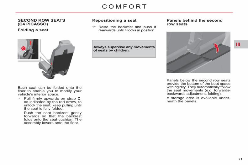
III
71
C O M F O R T
SECOND ROW SEATS(C4 PICASSO) Folding a seat
Each seat can be folded onto the fl oor to enable you to modify your vehicle’s interior space. Pull fi rmly upwards on strap C ,
as indicated by the red arrow, to unlock the seat; keep pulling until the seat is fully folded.
Push the seat backrest gently forwards so that the backrest folds onto the seat cushion. The assembly lowers onto the fl oor.
Repositioning a seat Raise the backrest and push it
rearwards until it locks in position
Always supervise any movements of seats by children.
Panels behind the second row seats
Panels below the second row seats provide the bottom of the boot space with rigidity. They automatically follow the seat movements (e.g. forwards-backwards adjustment, folding). A storage area is available under-neath the panels.

III
72
C O M F O R T
SECOND ROW REAR SEATS(GRAND C4 PICASSO)
Each seat can be folded onto the fl oor to form a fl at surface, thus en-abling you to adapt your vehicle’s interior space.
Folding a seat From the outside
Pull fi rmly upwards on strap C , as indicated by the red arrow, to unlock the seat; keep pulling until the seat is fully folded.
Push the seat backrest gently forwards so that the backrest folds onto the seat cushion. The assembly lowers onto the fl oor.
From the boot (when loading, for example) You can fold the second-row seat(s) from the boot, having fi rst folded the third-row seats. Pull on the strap D to unlock the
chosen seat, push the backrest gently forwards.
To prevent any damage to the mechanism, the strap D unclips under excessive force. Simply clip it back in place to render the system operational.
Repositioning a seat Return the second-row seat rigid
panels to their initial position and lock them in position.
Raise the backrest and push it rearwards until it locks in position.
Before moving the third-row seats, return the second-row rigid pan-els to their initial position and lock them in place. Never allow children to operate the seats without supervision.
Rigid panel
Each second-row seat backrest has a rigid panel attached. This panel enables you: - to have a continuous load sur-
face in the boot, whatever the positions of the seats,
- to avoid having objects sliding under the second-row seats.
Unlocking/Locking the rigid panel Slide the latch 1 on the panel
downwards, to unlock. Return the panel to the upright
position, then slide the latch 1 upwards, to lock.
Before positioning the rigid panels, check that the second-row seats are in the fully back position. 5-seater confi gurations do not have these rigid panels.

III
73
C O M F O R T
"Cinema seat" position
This position allows you to free up space between the fi rst row and the second row. Pull the lever E under the seat. This position is only possible with the outer seats.
Access to the third row seats
Access to the third-row seats is via the outer second-row seats. Pull the lever E . The seat unlocks
and the seat cushion comes up against the backrest.
Hold the lever E in the raised position, pushing forwards. The whole seat slides towards the front seat.
Space becomes free behind the seat, the third-row passengers can get to their seats.
Exit from the third row seats Hold the lever E in the raised po-
sition. The seat unlocks and the seat cushion comes up against the backrest.
Push the seat backrest, still hold-ing the lever E in the raised posi-tion.
If the table on the back of the fi rst-row seat is down, close it to enable this operation.
Repositioning a seat, from the outside, with the door open If there are passengers seated in the third row: manually return the assembly as
far as possible rearwards; the seat does not return as far as the maximum rearwards position so as to retain legroom for the third-row passengers,
fold the seat cushion until it locks.
Ensure that there is no object on or under the seat that you want to move.
Emergency exit: should the fi rst system fail (strap C ), use of the le-ver E allows third-row passengers to leave. Do not allow children to operate the seats without supervision.

III
74
C O M F O R T
THIRD ROW SEATS (GRAND C4 PICASSO)
Concertina boards
Two rigid concertina boards, which cannot be separated from the ve-hicle, cover the 2 third-row seats, when these are in the folded posi-tion.
Folding the concertina boards
Pull on the control, the 3 sections of the board will fold like a concertina. When the third-row seats are up-right, these concertina boards can be left either: - fl at behind the seats, - in the vertical position, thereby leaving a storage area avail-able.
Unfolding the seat
Return the second-row rigid panels to their initial position and lock them.
Having folded your concertina board, pull on the control F lo-cated behind the seat backrest. The backrest pivots rearwards, pulling the seat base with it. The seat locks in the open position.
Repositioning the seat Return the second-row rigid
panels to their initial position and lock them.
Lower the head restraints. Correctly position the concertina
board vertically behind the seat.
Pull on the control G , located at the bottom of the seat backrest. The seat unlocks.
Next push the backrest gently forwards. The backrest pivots, folding onto the seat base. The seat base then folds into the stowage area provided for that purpose.
Reposition the concertina boards over the folded seats.
Before moving the third-row seats, return the rigid plates of the second-row seats to the upright position and lock them. Do not try to fold a third-row seat that has not fi rst had the backrest fully locked in place. Do not leave objects either on or underneath the seat bases of the third-row seats when you are fold-ing them. Do not leave your hand on the con-trol G as you fold the seats, as you risk trapping your fi ngers. Do not allow children to operate the seats without supervision.
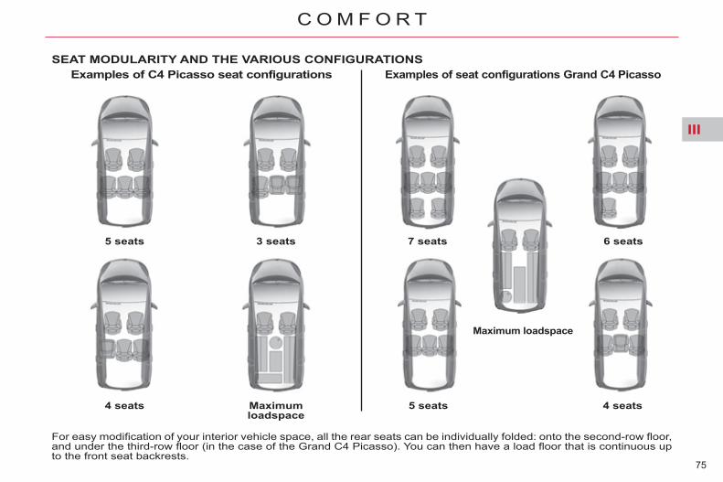
III
75
C O M F O R T
SEAT MODULARITY AND THE VARIOUS CONFIGURATIONS Examples of C4 Picasso seat configurations
5 seats
4 seats
3 seats
Maximum loadspace
Examples of seat configurations Grand C4 Picasso
7 seats 6 seats
5 seats 4 seats
Maximum loadspace
For easy modifi cation of your interior vehicle space, all the rear seats can be individually folded: onto the second-row fl oor, and under the third-row fl oor (in the case of the Grand C4 Picasso). You can then have a load fl oor that is continuous up to the front seat backrests.

III
76
C O M F O R T
MIRRORS
Door mirrors Each mirror is adjustable to provide the rear view needed for overtaking or parking. They can also be folded for parking in confi ned spaces.
Adjustment With the ignition on: move control A to the right or to
the left to select the correspond-ing mirror,
move control B in one of four di-rections to adjust,
return control A to the central po-sition.
The objects observed are, in reality, closer than they appear. Take this into account in order to correctly judge the distance of ve-hicles approaching from behind.
Folding From outside: lock the vehicle
using the remote control or the key.
From inside: with the ignition on, pull the control A in the central position rearwards.
If the mirrors are folded using con-trol A , they will not unfold when the vehicle is unlocked. Pull again on control A .
Unfolding From outside: unlock the vehicle
using the remote control or the key.
From inside: with the ignition on, pull the control A in the central position rearwards.
The folding and unfolding of the door mirrors using the remote control can be deactivated by a CITROËN dealer or a qualifi ed workshop. Never fold or unfold the electric fold-ing mirrors manually.
Automatic tilting in reverse gear System which provides a view of the ground during parking manoeuvres in reverse gear.
Programming With the engine running, engage
reverse gear. Select and adjust the left-hand
and right-hand mirrors in suc-cession.
The adjustment is stored immedi-ately.
Switching off Exit reverse gear and wait ten seconds. or Return control A to the central
position. The mirror glass returns to its initial position. The mirror glass also returns to its initial position: - if the speed exceeds 6 mph (10 km/h), - if the engine is switched off.
Switching on With the engine running, engage
reverse gear. Move control A to the right or to
the left to select the correspond-ing mirror.
The glass of the mirror selected tilts downwards, in accordance with its programming.
The demisting/defrosting of the door mirrors is linked to that of the rear screen.

III
77
C O M F O R T
Rear view mirror Adjustable mirror providing a central rearward view. Equipped with an anti-dazzle sys-tem, which darkens the mirror glass: this reduces the nuisance to the driver caused by the headlamps from following vehicles, low sun...
Manual day/night model
Adjustment Adjust the mirror so that the
glass is directed correctly in the "day" position.
Day/night position Pull the lever to change to the
"night" anti-dazzle position. Push the lever to change to the
normal "day" position.
By means of a sensor, which mea-sures the light from the rear of the vehicle, this system automatically and progressively changes between the day and night uses.
STEERING WHEEL ADJUSTMENT The height and reach of the steer-ing wheel can be adjusted to adapt the driving position to the size of the driver.
Adjustment First, adjust the driver's seat to
the most suitable position. When stationary , pull the control
lever to unlock the steering wheel adjustment.
Adjust for height and reach. Push the control lever to lock the
steering wheel adjustment. After locking, if you press fi rmly on the steering wheel, a slight click may be heard.
As a safety measure, the mirrors should be adjusted to reduce the "blind spot".
Automatic day/night model
As a safety precaution, these operations must only be carried out while the vehicle is stationary.
In order to ensure optimum visibility during your manoeuvres, the mirror lightens automatically when reverse gear is engaged.

IV
78
A C C E S S
REMOTE CONTROL KEY
System which permits central un-locking or locking of the vehicle us-ing the door lock or remotely. It is also used to locate the vehicle, acti-vate the guide-me-home lighting and start the engine, as well as providing protection against theft.
Unlocking the vehicle
Complete unlocking using the remote control
Unfolding the key First press this button to unfold
the key.
Press the open padlock to unlock the vehicle.
Complete unlocking using the key Turn the key to the left in the
driver's door lock to unlock the vehicle.
Unlocking is confi rmed by rapid fl ashing of the direction indicators for approximately two seconds. According to version, the door mir-rors unfold at the same time. This also triggers the timed illumina-tion of the exterior side spotlamps and the interior welcome lighting for a period of thirty seconds.
Selective unlocking using the remote control
Press the open pad-lock once to unlock the driver's door only.
According to version, the door mir-rors unfold at the same time as the fi rst unlocking action. It also triggers the timed operation of the exterior side spotlamps and the interior welcome lighting for thirty seconds.
The complete or se-lective unlocking pa-rameter is set via the multifunction screen confi guration menu.
Complete unlocking is activated by default.
Unlocking is confi rmed by rapid fl ashing of the direction indicators for approximately two seconds.
Selective unlocking is not available using the key.
Press the open padlock again to unlock the other doors and the boot.

IV
79
A C C E S S
Normal locking using the key Turn the key to the right in the
driver's door lock to lock the ve-hicle.
To allow long objects to be carried, the vehicle can be locked from the inside, using the central locking control on the dashboard, even if the tailgate or rear screen is open. When the vehicle is locked, if it is unlocked inadvertently, it will lock itself again automatically after thirty seconds unless a door is opened. When closing the windows and/or panoramic sunroof blind using the remote control, you must ensure that no one prevents them from closing correctly. The folding and unfolding of the door mirrors using the remote control can be deactivated by a CITROËN dealer or a qualifi ed workshop.
Deadlocking using the remote control
Press the closed pad-lock to lock the vehicle completely or press the closed padlock for more than two seconds to close the windows and the panoramic sunroof blind automatically in addition to locking.
Press the closed padlock again within fi ve seconds to deadlock the vehicle.
Locking the vehicle
Normal locking using the remote control
Briefl y press the closed padlock to lock the ve-hicle.
Make a long press on the closed padlock to lock the vehicle and also close the windows and the panoramic sunroof blind.
Locking is confi rmed by fi xed light-ing of the direction indicators for ap-proximately two seconds. According to version, the door mir-rors fold at the same time. Locking also triggers the timed switching on of the exterior side spotlamps and the guide-me-home lighting, if this is activated.
If one of the doors, the rear screen or the boot is still open, the central locking does not take place.

IV
80
A C C E S S
Deadlocking using the key
Turn the key to the right in the driv-er's door lock to lock the vehicle completely and hold it in this posi-tion for more than two seconds to close the windows automatically in addition to locking.
Turn the key to the right again within fi ve seconds to deadlock the vehicle.
Deadlocking renders the exterior and interior door controls inoperative. It also deactivates the manual cen-tral control button. Therefore, never leave anyone in-side the vehicle when it is dead-locked.
Deadlocking also triggers the timed illumination of the exterior side spot lamps and guide-me-home lighting, if this is activated.
First press this button to fold the key.
If you do not press the button when folding the key, there is a risk of damage to the mechanism.
Locating your vehicle This function allows you to identify your vehicle from a distance, espe-cially when the light is poor. Your ve-hicle must be locked. Press the closed padlock on the
remote control. This will bring on the courtesy lamps and exterior side spotlamps, as well as fl ashing the direction indicators for a few seconds.
Remote operation of lighting
Anti-theft protection Electronic engine immobiliser The key contains an electronic chip which has a special code. When the ignition is switched on, this code must be recognised in order for starting to be possible. This electronic engine immobiliser locks the engine management sys-tem a few minutes after the ignition is switched off and prevents starting of the engine by anyone who does not have the key.
In the event of a fault, you are informed by il-lumination of this warn-ing lamp, an audible
signal and a message in the screen. In this case, your vehicle will not start; contact a CITROËN dealer as soon as possible. Keep safely the label attached to the keys given to you on acquisition of the vehicle.
Folding the key
A press on this button brings on the temporary illumination of sidelamps, dipped beam headlamps, number plate lamps and
the exterior side spotlamps located underneath the door mirrors. A second press before the end of the timed period cancels the command.
Deadlocking is confi rmed by fi xed lighting of the direction indicators for approximately two seconds. According to version, the door mir-rors fold at the same time.

IV
81
A C C E S S
STARTING
1. "S": Steering lock To unlock the steering, gently move the steering wheel while turning the key, without forcing it.
2. "M": Ignition on Depending on the version of your vehicle, the orange and red warn-ing lamps should also come on for a short time.
3. "D": Starter Release the key as soon the engine has started. If the fi rst attempt fails, switch off the ignition. Wait ten seconds then oper-ate the starter again.
Steering lock 1. " S": After removing the key, turn
the steering wheel to lock the steering. The key can only be removed in position S .
2. "M": Ignition switched on, the steering is unlocked (by turning the key to position M , move the steering wheel gently if necessary).
3. "D": Starter position.
Key left in position "M" audible warning If you forget to remove the key from the ignition, the ignition is switched off automatically after one hour. To switch the ignition back on, turn the key to position S then back to position M .
Do not run the engine in an en-closed space or where there is insuffi cient ventilation . You must always to keep the engine running when moving in order to retain braking and steer-ing power assistance . Never remove the ignition key before the vehicle has come to a complete stop.
Vehicles equipped with a turbocharger Never stop the engine without having allowed it to run for a few seconds at idle, this being the time required for the turbocharger to return to a normal speed. Flicking the accelerator at the mo-ment of switching off the ignition could cause serious damage.
A heavy object (key fob...), attached to the key and weighing down on its shaft in the ignition switch, could cause a malfunction.
Never turn the key to this position when the engine is running.

IV
82
A C C E S S
Remote control problems Following disconnection of the ve-hicle battery, replacement of the re-mote control battery or in the event of a remote control malfunction, you can no longer unlock, lock or locate your vehicle. First of all, use the key in the lock
to unlock or lock your vehicle. Then, reinitialise the remote control.
Reinitialisation Switch off the ignition. Turn the key to position 2 (Ignition on) . Press the closed padlock imme-
diately for a few seconds. Switch off the ignition and re-
move the key from the ignition switch.
The remote control is fully opera-tional again.
Battery ref.: CR1620/3 volts.
If the remote control bat-tery is fl at, you are in-formed by lighting of this warning lamp, an audible signal and a message on the multifunction screen.
Unclip the casing using a coin at the notch.
Slide the fl at battery out of its lo-cation.
Slide the new battery into its lo-cation observing the original di-rection.
Clip the casing together. Reinitialise the remote control.
Changing the battery
If the problem persists, contact a CITROËN dealer as soon as pos-sible.

IV
83
A C C E S S
Lost keys Visit a CITROËN dealer with the ve-hicle's registration document, your personal identifi cation documents and if possible the key code label. The CITROËN dealer will be able to fi nd the key code and the transpon-der code required to order a new key.
Remote control The high frequency remote control is a sensitive system; do not operate it while it is in your pocket as there is a possibility that it may unlock the ve-hicle, without you being aware of it. Do not repeatedly press the buttons of your remote control out of range and out of sight of your vehicle. You run the risk of stopping it from work-ing and the remote control would have to be reinitialised. The remote control does not operate when the key is in the ignition switch, even when the ignition is switched off, except for reinitialisation.
Locking the vehicle Driving with the doors locked may make access to the passenger com-partment by the emergency services more diffi cult in an emergency. As a safety precaution (with children on board), remove the key from the ignition switch when you leave the vehicle, even for a short time.
Anti-theft protection Do not make any modifi cations to the electronic engine immobiliser system; this could cause malfunc-tions.
When purchasing a second-hand vehicle Have the pairing of all of the keys in your possession checked by a CITROËN dealer, to ensure that only your keys can be used to open and start the vehicle.
Do not throw the remote control batteries away, they contain metals which are harmful to the environment.
Take them to an approved collection point.

IV
84
A C C E S S
ALARM System which protects and provides a deterrent against theft and break-ins. It provides the following types of monitoring.
- Exterior perimeter The system checks for opening of the vehicle. The alarm is triggered if anyone tries to open a door, the boot, the bonnet...
- Interior volumetric The system checks for any variation in the volume in the passenger com-partment. The alarm is triggered if anyone breaks a window, enters the pas-senger compartment or moves in-side the vehicle.
Self-protection function The system checks for the putting out of service of its components. The alarm is triggered if the battery, the central control or the wires of the siren are put out of service or dam-aged.
Locking the vehicle with full alarm system
Activation Switch off the ignition and get out
of the vehicle. Press the locking button on the
remote control.
Deactivation Press the unlocking button on
the remote control. The alarm system is deactivated: the indicator lamp in the button goes off.
If an opening (door, boot...) is not closed fully, the vehicle is not locked but the exterior perimeter monitor-ing will be activated after a delay of 45 seconds at the same time as the interior volumetric monitoring.
The monitoring system is active: the indicator lamp in the button fl ashes once per second. After the locking button on the re-mote control is pressed, the exterior perimeter monitoring is activated after a delay of 5 seconds and the interior volumetric monitoring after a delay of 45 seconds.
For all work on the alarm system, contact a CITROËN dealer or a qualifi ed workshop.
IV
85
A C C E S S
Locking the vehicle with exterior perimeter monitoring only Deactivate the interior volumetric monitoring to avoid unwanted trig-gering of the alarm in certain cases such as: - leaving a pet in the vehicle, - leaving a window partially open, - washing your vehicle,
To be effective, this deactivation must be carried out each time the ignition is switched off.
Deactivation of the interior volumetric monitoring Switch off the ignition. Within ten seconds, press the
button until the indicator lamp is on continuously.
Get out of the vehicle. Press the locking button on the
remote control immediately. The exterior perimeter monitoring alone is activated: the indicator lamp in the button fl ashes once per second.
Triggering of the alarm
The monitoring functions remain active until the alarm has been trig-gered eleven times in succession. When the vehicle is unlocked using the remote control, rapid fl ashing of the indicator lamp in the button informs you that the alarm was trig-gered during your absence. When the ignition is switched on, this fl ashing stops immediately.
Failure of the remote control To deactivate the monitoring func-tions:
Locking the vehicle without activating the alarm
Malfunction
Automatic activation *
Lock or deadlock the vehicle us-ing the key in the driver's door lock.
When the ignition is switched on, fi xed il-lumination of the indicator lamp in the but-ton indicates a malfunction of the system. Have it checked by a CITROËN dealer or a qualifi ed workshop.
2 minutes after the last door or the boot is closed, the system is activat-ed automatically. To avoid triggering the alarm on
entering the vehicle, fi rst press the unlocking button on the re-mote control.
Unlock the vehicle using the key in the driver's door lock.
Open the door; the alarm is trig-gered.
Switch on the ignition; the alarm stops. The indicator lamp in the button goes off.
This is indicated by sounding of the siren and fl ashing of the direction in-dicators for thirty seconds.
Reactivation of the interior volumetric monitoring Press the unlocking button on the
remote control to deactivate the exterior perimeter monitoring.
Press the locking button on the remote control to activate all the monitoring functions.
The indicator lamp in the button again fl ashes once per second.
* According to country.

IV
86
A C C E S S
ELECTRIC WINDOWS System intended to open or close a window manually or automatically. Fitted with a safety anti-pinch system and a system for deactivation in the event of misuse of the rear controls.
1. Driver's electric window control.
2. Passenger's electric window control.
3. Rear right electric window control.
4. Rear left electric window control.
5. Deactivation of the rear electric window and door controls.
One-touch electric windows There are two options:
- automatic mode Press or pull the control fi rmly. The window opens or closes fully when the control is released.
Pressing the control again stops the movement of the window.
The electric window controls re-main operational for approximately 45 seconds after the ignition is switched off or until the vehicle is locked after a door is opened. If one of the passenger windows cannot be operated from the driv-er's door control panel, carry out the operation from the control panel of the passenger door con-cerned, and vice versa.
Safety anti-pinch When the window rises and meets an obstacle, it stops and partially lowers again.
If the window cannot be closed (for example, in the presence of ice), immediately after the movement is reversed: press and hold the control until
the window opens fully, then pull the control immediate-
ly and hold it until the window closes,
continue to hold the control for approximately one second after the window has closed.
The safety anti-pinch function is not operational during these operations.
- manual mode Press or pull the control gently.
The window stops when the control is released.

IV
87
A C C E S S
Reinitialisation If a window does not rise automati-cally, its operation must be reini-tialised: pull the control until the window
stops, release the control and pull it
again until the window closes fully,
continue to hold the control for approximately one second after the window has closed,
press the control to lower the window automatically to the low position,
when the window has reached the low position, press the con-trol again for approximately one second.
The safety anti-pinch function is not operational during these operations.
Deactivation of the rear electric window and door controls
For the safety of your children, press control 5 to deactivate the rear electric window controls re-gardless of their position.
Always remove the key from the ignition when leaving the vehicle, even for a short time. If an obstacle is encountered during operation of the electric windows, you must reverse the movement of the window. To do this, press the control concerned. When the driver operates the con-trols for the passengers' electric windows, they must ensure that no one is preventing correct closing of the windows. The driver must ensure that the passengers use the electric win-dows correctly. Be aware of children when operat-ing the windows.
This warning lamp comes on temporarily on the instru-ment panel on deactivation and each time the ignition is switched on.
This control also deactivates the interior controls for the rear doors (refer to the section "Child safety - Electric child lock").

IV
88
A C C E S S
DOORS
Opening
From outside
When the selective unlocking is activated, the fi rst press of the remote control unlocking button permits unlocking of the driver's door only.
Pull the interior control lever of a front door; this unlocks the ve-hicle completely.
With the selective unlocking acti-vated: - the driver's door control unlocks
the driver's door only, - the other door controls unlock
the other doors and the boot. The interior door controls do not operate when the vehicle is dead-locked.
Manual central locking control System for locking or unlocking the vehicle - the doors and boot - from the driving position.
Locking Press this button to lock the ve-
hicle. The red indicator lamp on the button comes on.
If one of the doors is open, the cen-tral locking does not take place. If the boot or the rear screen is open, central locking from the in-side is active for the doors, to allow long objects to be carried.
After unlocking the vehicle com-pletely using the remote control or the key, pull the door handle.
From inside

IV
89
A C C E S S
Unlocking Press this button again to unlock
the vehicle. The red indicator lamp on the button goes off.
If the vehicle is locked or dead-locked from the outside, the red in-dicator lamp fl ashes and button A is inactive. In this case, use the remote
control or the key to unlock the vehicle.
Automatic central locking This system automatically locks the doors, boot and rear screen while driving. You can activate or deactivate this function.
Locking When the speed exceeds 6 mph (10 km/h), the doors, the boot and the rear screen lock automatically.
Unlocking Above 6 mph (10 km/h), press
this button to unlock the doors, the boot and the rear screen temporarily.
Ignition on:
Deactivation Press this button again for more
than two seconds. A confi rmation message appears in the multifunction screen.
Emergency control System which locks or unlocks the doors mechanically in the event of a malfunction of the battery or of the central locking.
Locking the driver's door Insert the key in the lock, then
turn it to the right.
Unlocking the driver's door Insert the key in the lock, then
turn it to the left.
Locking the front and rear passenger doors
Insert the key in the lock, located on the edge of the door, then turn it one eighth of a turn .
Unlocking the front and rear passenger doors Pull the interior door opening
control.
If one of the doors or the boot or rear screen is open, the automat-ic central locking does not take place.
Activation Press this button for more than
two seconds. A confi rmation message appears in the multifunction screen.
In the event of a fault with the cen-tral locking, you must disconnect the battery to lock the boot and so ensure the complete locking of the vehicle.

IV
90
A C C E S S
BOOT
After unlocking the vehicle com-pletely using the remote control or the key, with the rear screen closed, pull on the lever 1 and raise the tailgate.
Lower the tailgate using one of the two handholds 3 , located on the interior trim.
- when the engine is running , this warning lamp comes on, accom-panied by a message in the multifunction screen for a few seconds,
- when the vehicle is moving (speed above 6 mph (10 km/h)), this warning lamp comes on, ac-companied by an audible signal and a message in the multifunc-tion screen for a few seconds.
If the tailgate is not closed correctly:
REAR SCREEN
This opening gives easy access to the boot, even if you are parked close to a wall or another vehicle.
Closing Lower the rear screen guiding
it with the wiper arm until it is closed.
If the rear screen is not closed cor-rectly:
- when the engine is running , this warning lamp comes on, accom-panied by a message in the multifunction screen for a few seconds,
- when the vehicle is moving (speed above 6 mph (10 km/h)), this warning lamp comes on, ac-companied by an audible signal and a message in the multifunc-tion screen for a few seconds.
The boot and the rear screen cannot both be open at the same time.
When the rear screen is open, you can access the boot by rais-ing the rear shelf using its tab (C4 Picasso). After unlocking the vehicle com-
pletely using the remote control or the key, with the boot closed, press the control 2 and raise the rear screen using the base 4 of the wiper arm.
Past the balancing point, allow the tailgate to lower and close itself (do not assist it or slow it down).
Opening
Opening Closing

IV
91
A C C E S S
Emergency boot release System for mechanical unlocking of the boot in the event of a battery or central locking malfunction.
Unlocking Fold back the rear seats to gain
access to the lock from inside the boot.
Insert a small screwdriver into hole A of the lock to unlock the tailgate.
Push the white part, located in-side the lock, to the left to unlock the boot.
PANORAMIC SUNROOF
It is fi tted with an electrically con-trolled blind.
Opening the roof blind Rotate the control knob B to slide
the roof blind to the desired posi-tion (positions 1 to 9 ).
Closing the roof blind Rotate the control knob B to po-
sition 0 to close the roof blind.
Recommendations - Pressing the locking button on
the remote control for more than two seconds will close the blind (practical when, for example, you leave your vehicle in a sunlit car park).
- On returning to your vehicle, a press on control knob B reposi-tions the blind to the last position selected.
Anti-pinch The blind has an anti-pinch func-tion. At the end of its travel, when the blind encounters an obstacle on closing, it stops and moves back slightly. Following a fault or after a battery disconnection during the movement of the blind or after it has stopped, you must re-initialise the anti-pinch function: place the blind in the closed po-
sition, press control knob B for approxi-
mately two seconds.

IV
92
A C C E S S
FUEL TANK
Capacity of the tank: approxi-mately 60 litres.
Low fuel level
When the low fuel level is reached, this warning lamp on the instrument panel comes on, accompanied by
an audible warning and a message on the multifunction screen. When it fi rst comes on, about 7 litres of fuel remain in the tank. Until suffi cient fuel has been added, this warning lamp appears every time the ignition is switched on, accompanied by an audible warning and a message. Depending on version, this audible warning and message are repeated with increasing frequency as the fuel level drops towards " 0 ". Refuel as soon as possible to avoid running out.
A label on the inside of the fuel fi ller fl ap reminds you of the type of fuel to use, depending on your engine type.
Additions of fuel must be of at least 5 litres to be registered by the fuel gauge.
Refuelling
If you are fi lling your tank to the top, do not persist after the 3rd cut-off; this could cause malfunctions.
With Stop & Start, never refuel with the system in STOP mode; you must switch off the ignition with the key.
Opening the fi ller cap may result in an inrush of air. This is entirely nor-mal and results from the sealing of the fuel system. Press control switch A , situated
on the switch panel on the left of the dashboard, until the fuel fl ap opens.
This control switch remains ac-tive for a few minutes after switching of the ignition. If nec-essary, switch the ignition on again to reactivate it.
Take care to select the pump that delivers the correct type of fuel for your vehicle.
Introduce the nozzle so as to push in the metal non-return fl ap B.
Make sure that the nozzle is pushed in as far as possible before starting to refuel (risk of blowback).
Maintain this position throughout the refuelling operation.
Push the fuel fl ap to close it.
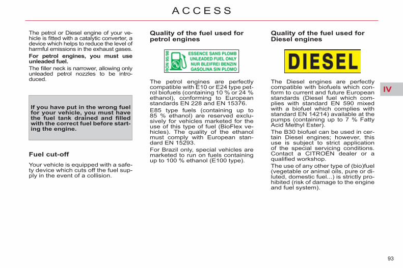
IV
93
A C C E S S
The petrol or Diesel engine of your ve-hicle is fi tted with a catalytic converter, a device which helps to reduce the level of harmful emissions in the exhaust gases. For petrol engines, you must use unleaded fuel. The fi ller neck is narrower, allowing only unleaded petrol nozzles to be intro-duced.
If you have put in the wrong fuel for your vehicle, you must have the fuel tank drained and fi lled with the correct fuel before start-ing the engine.
Quality of the fuel used for petrol engines
Quality of the fuel used for Diesel engines
Fuel cut-off Your vehicle is equipped with a safe-ty device which cuts off the fuel sup-ply in the event of a collision.
The petrol engines are perfectly compatible with E10 or E24 type pet-rol biofuels (containing 10 % or 24 % ethanol), conforming to European standards EN 228 and EN 15376. E85 type fuels (containing up to 85 % ethanol) are reserved exclu-sively for vehicles marketed for the use of this type of fuel (BioFlex ve-hicles). The quality of the ethanol must comply with European stan-dard EN 15293. For Brazil only, special vehicles are marketed to run on fuels containing up to 100 % ethanol (E100 type).
The Diesel engines are perfectly compatible with biofuels which con-form to current and future European standards (Diesel fuel which com-plies with standard EN 590 mixed with a biofuel which complies with standard EN 14214) available at the pumps (containing up to 7 % Fatty Acid Methyl Ester). The B30 biofuel can be used in cer-tain Diesel engines; however, this use is subject to strict application of the special servicing conditions. Contact a CITROËN dealer or a qualifi ed workshop. The use of any other type of (bio)fuel (vegetable or animal oils, pure or di-luted, domestic fuel...) is strictly pro-hibited (risk of damage to the engine and fuel system).

V
94
V I S I B I L I T Y
EXTERIOR LIGHTING CONTROLS Control stalk for the selection and con-trol of the various front and rear lamps providing the vehicle's lighting.
Main lighting The various front and rear lamps of the vehicle are designed to adapt the driver's visibility progressively in relation to the climatic conditions: - sidelamps, to be seen, - dipped beam headlamps to see
without dazzling other drivers, - main beam headlamps to see
clearly when the road is clear.
Additional lighting Other lamps are fi tted to fulfi l the require-ments of particular driving conditions: - a rear foglamp to be seen from a
distance, - front foglamps for even better
forward vision, - directional headlamps for improved
visibility when cornering, - daytime running lamps to be
seen during the day.
Programming Various automatic lighting control modes are also available depending on options: - guide-me-home lighting, - automatic illumination of headlamps, - directional lighting.
Manual controls
Lamps off.
Automatic illumination of head-lamps.
Sidelamps.
Dipped headlamps or main beam headlamps.
B. Stalk for switching headlam-ps: pull the stalk towards you to switch the lighting between dipped and main beam head-lamps.
In the lamps off and sidelamps modes, the driver can switch on the main beam headlamps temporarily ("headlamp fl ash") by maintaining a pull on the stalk.
Displays Illumination of the corresponding indicator lamp in the instrument pan-el confi rms that the lighting selected is on.
The lighting is controlled directly by the driver by means of the ring A and the stalk B .
A. Main lighting mode selection ring: turn it to position the symbol required facing the mark.

V
95
V I S I B I L I T Y
C. Foglamps selection ring. The foglamps operate with the side-lamps and the dipped and main beam headlamps.
- 1 st turn forwards: rear foglamp on. - 1 st turn rearwards: rear foglamp off.
- 1 st turn forwards: front foglamps on. - 2 nd turn forwards: rear foglamps on. - 1 st turn rearwards: rear foglamps off. - 2 nd turn rearwards: front foglamps off.
Model with rear foglamp only Model with front and rear foglamps
In good or rainy weather, both day and night, use of the front foglamps and the rear foglamp is prohibited. In these situations, the power of their beams may dazzle other dri-vers. They should only be used in fog or snow. In these weather conditions, it is your responsibility to switch on the foglamps and dipped beam head-lamps manually as the sunshine sensor may detect suffi cient light. Do not forget to switch off the front foglamps and the rear foglamp when they are no longer necessary.
Switching off the lamps when the ignition is switched off On switching off the ignition, all of the lamps turn off immediately, except for the dipped beam headlamps if guide-me-home lighting is activated.
In some weather conditions (e.g. low temperature or humidity), the pres-ence of misting on the internal sur-face of the glass of the headlamps and rear lamps is normal; it disap-pears after the lamps have been on for a few minutes.
Switching on the lamps after the ignition is switched off To reactivate the lighting control, rotate ring A to the "0" position - lamps off, then to the desired position. On opening the driver's door a temporary audible signal warns the driver that the lighting is on. The lamps, with the exception of the sidelamps, switch off automati-cally after a period that depends on the state of charge of the battery (entering energy economy mode).
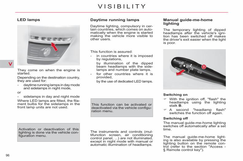
V
96
V I S I B I L I T Y
Daytime running lamps Daytime lighting, compulsory in cer-tain countries, which comes on auto-matically when the engine is started making the vehicle more visible to other users.
Manual guide-me-home lighting The temporary lighting of dipped headlamps after the vehicle's igni-tion has been switched off makes the driver's exit easier when the light is poor.
Switching on With the ignition off, "fl ash" the
headlamps using the lighting stalk B .
A second "headlamp fl ash" switches the function off again.
Switching off The manual guide-me-home lighting switches off automatically after a set time.
The manual guide-me-home light-ing is also available by pressing the lighting button on the remote con-trol (refer to the section "Access - § Remote control key").
This function is assured: - in countries where it is imposed
by regulations, by illumination of the dipped
beam headlamps with the side-lamps and number plate lamps.
- for other countries where it is provided,
by the use of dedicated LED lamps.
The instruments and controls (mul-tifunction screen, air conditioning control panel, ...) are not illuminated, except in night mode with manual or automatic illumination of headlamps.
LED lamps
They come on when the engine is started. Depending on the destination country, they are used for: - daytime running lamps in day mode
and sidelamps in night mode, or - sidelamps in day and night mode Where LED lamps are fi tted, the fi la-ment bulbs for the sidelamps in the front lamp units are not used.
Activation or deactivation of this lighting is done via the vehicle con-fi guration menu.
This function can be activated or deactivated via the vehicle confi gu-ration menu.

V
97
V I S I B I L I T Y
Automatic illumination of headlamps When a low level of ambient light is detected by a sunshine sensor, the number plate lamps, sidelamps and dipped beam headlamps are switched on automatically, without any action on the part of the driver. They can also come on if rain is de-tected, at the same time as auto-matic operation of the windscreen wipers. As soon as the brightness returns to a suffi cient level or after the wind-screen wipers are switched off, the lamps are switched off automatically.
Activation Turn ring A to the "AUTO" posi-
tion. The activation of the function is accompanied by a message in the screen.
Deactivation Turn ring A to a position other
than "AUTO" . Deactivation of the function is accompanied by a message in the screen.
Operating fault In the event of a malfunction of the sunshine sensor, the lamps comes on, a message appears in the screen, accompanied by an audible signal. Contact a CITROËN dealer or a qualifi ed workshop.
Automatic "guide-me-home" lighting When the automatic illumination of headlamps function is activated, under low ambient light the dipped beams headlamps come on au-tomatically when the ignition is switched off.
In fog or snow, the sunshine sensor may detect suffi cient light. Therefore, the lighting will not come on auto-matically. Do not cover the sunshine sen-sor, linked with the rain sensor and located in the centre of the wind-screen behind the rear view mirror; the associated functions would no longer be controlled.
Programming The activation and the duration of the guide-me-home lighting can be set in the vehicle confi guration menu. For a vehicle fi tted with the mono-chrome screen A, the duration is fi xed.

V
98
V I S I B I L I T Y
OF XENON HEADLAMPS
This system adjusts the height of the xenon headlamp beams automati-cally and when stationary, according to the load in the vehicle, so as to avoid causing a nuisance to other road user.
If a malfunction occurs, this warning lamp is dis-played in the instrument panel, accompanied by
an audible signal and a message in the screen. The system then places your head-lamps in the lowest position.
Do not touch the xenon bulbs. Contact a CITROËN dealer or a qualifi ed workshop.
MANUAL ADJUSTMENT OFHEADLAMPS
To avoid dazzling other road users, the height of the halogen bulb head-lamps must be adjusted according to the load in the vehicle. To do this, turn the control, located below the dashboard to the left of the driver, to the appropriate position: 0. 1 or 2 people in the front seats. -. 3 people. 1. 4 to 7 people. -. Intermediate setting. 2. 4 to 7 people + maximum autho-
rised loads. -. Intermediate setting. 3. Driver + maximum authorised loads.
Initial setting is position " 0 ".
EXTERIOR SIDE SPOTLAMPS
Switching on The side spotlamps come on tempo-rarily: - when you unlock the vehicle, - when you press the lighting button
on the remote control, - with the automatic guide-me-home
lighting, on switching off the ignition, - when you remove the key from
the ignition, - when you open a door, - when you use the remote control
to locate the vehicle.

V
99
V I S I B I L I T Y
DIRECTIONAL LIGHTING When the dipped or main beam headlamps are on, this function en-ables the light beam to follow the di-rection of the road. The use of this function, coupled with the xenon headlamps only, considerably improves the quality of your lighting when cornering.
with directional lighting
without directional lighting
Programming
The function is activat-ed or deactivated via the multifunction screen confi guration menu.
Operating fault If a malfunction occurs, this warning lamp fl ashes on the instrument panel, accompa-nied by a message on the multifunction screen.
Contact a CITROËN dealer or a qualifi ed workshop.
When stationary or moving at very low speed or when reverse gear is engaged, the system is inactive. The status of the system remains in the memory when the ignition is switched off. On vehicles fi tted with daytime run-ning lamps, the function is activated if the lighting stalk is in the "AUTO" or "Dipped/main beam headlamps" position. In position "0" , the function is not activated.

V
100
V I S I B I L I T Y
WIPER CONTROLS System for selection and control of the various front and rear wiping modes for the elimination of rain and cleaning. The vehicle's front and rear wipers are designed to improve the driver's visibility progressively according to the climatic conditions.
Programming Various automatic wiper control modes are also available according to the following options: - automatic rain sensitive windscreen
wipers, - rear wiping on engaging reverse
gear.
Manual controls The wiper commands are issued di-rectly by the driver by means of the stalk A and the ring B .
Rear wiper
B. Rear wiper selection ring:
park,
intermittent wipe,
wash-wipe (set duration).
fast (heavy rain),
normal (moderate rain),
intermittent (proportional to the speed of the vehicle),
automatic, then single wipe (see following page).
park,
single wipe (press down and release),
Windscreen wipers A. Wiping speed selection stalk:
or
If a signifi cant accumulation of snow or ice is present, or when using a tailgate bicycle carrier, deactivate the automatic rear wiper via the multifunction screen confi guration menu.

V
101
V I S I B I L I T Y
Reverse gear When reverse gear is engaged, the rear wiper will come into operation if the windscreen wipers are operating.
Programming
The function is activated or deactivated via the vehicle confi guration menu. This function is activated by default.
Windscreen and headlamp wash Pull the windscreen wiper stalk
towards you. The windscreen wash then the windscreen wip-ers operate for a fi xed period.
The headlamp washers only operate when the dipped beam headlamps are on .
Automatic rain sensitive windscreen wipers The windscreen wipers operate au-tomatically, without any action on the part of the driver, if rain is detected (sensor behind the rear view mirror), adapting their speed to the intensity of the rainfall.
This is controlled manually by the driver by pushing the stalk down-wards to the "AUTO" position. It is accompanied by a message in the screen.
The automatic rain sensitive wipers must be reactivated if the ignition has been off for more than one minute, by pushing the stalk downwards.
Operating fault If an automatic wiping malfunction occurs, the wipers will operate in in-termittent mode. Have it checked by a CITROËN dealer or a qualifi ed workshop.
Do not cover the rain sensor, linked with the sunshine sensor and locat-ed in the centre of the windscreen behind the rear view mirror. Switch off the automatic rain sen-sitive wipers when using an auto-matic car wash. In winter, to avoid damaging the wiper blades, it is advisable to wait until the windscreen is completely clear of ice before activating the automatic rain sensitive wipers.
Activation
Switching off
This is controlled manually by the driver by moving the stalk upwards then returning it to position "0" . It is accompanied by a message in the screen.

V
102
V I S I B I L I T Y
Special position of the windscreen wipers
This position permits release of the windscreen wiper blades. It is used for cleaning or replacement of the blades. It can also be useful, in winter, to detach the blades from the windscreen.
To maintain the effectiveness of the "fl at-blade" type of wiper blades, it is advisable to: - handle them with care, - clean them regularly using soapy
water, - avoid using them to retain card-
board on the windscreen, - replace them at the fi rst signs
of wear.
Any action on the wiper stalk in the minute after switching off the ignition places the blades verti-cally on the screen.
To park the blades again, switch on the ignition and operate the wiper stalk.

V
103
V I S I B I L I T Y
COURTESY LAMPS
1. Front courtesy lamp 2. Map reading lamps
Front courtesy lamp
In this position, the courtesy lamp comes on gradually:
Permanently off.
Permanent lighting.
In permanent lighting mode, different lighting times are available: - with the ignition off, approxi-
mately ten minutes, - in energy economy mode, approxi-
mately thirty seconds, - with the engine running, unlimited.
- when the vehicle is unlocked, - when a door or the boot is
opened, - when the key is removed from
the ignition, - when the remote control locking
button is activated, in order to locate your vehicle.
It switches off gradually: - when the vehicle is locked, - when the ignition is switched on, - 30 seconds after the last door is
closed.
Map reading lamps With the ignition on, press the
corresponding switch.
Panoramic sunroof courtesy lamps These courtesy lamps have two oper-ating modes: - automatic lighting when a door is
opened or when the front cour-tesy lamp is in the "permanent lighting" position,
- permanent lighting.
Opening the boot switches on the third row courtesy lamp and the boot lamps.

V
104
V I S I B I L I T Y
LIGHTING PACK
Interior mood lighting
This function activates the light sources which are located in the dashboard, near the interior door levers and in the roof.
Operation
This back-lit control, located near the steering wheel below the dash-board, is used to switch on and off and adjust the brightness of this lighting.
To increase brightness: Press the right of the control to
obtain the desired level.
To reduce brightness: Press the left of the control to obtain
the desired level. The setting is stored when the ignition is switched off.
Interior welcome lighting
When unlocking the vehicle with the remote control or the key, the foot-well lamps, interior lamps and interior mood lighting sources come on for 30 seconds. This function cannot be deactivated.
Front door pockets with automatic lighting The lighting for the door pockets comes on automatically when you place a hand inside one of the com-partments. It goes off after a few seconds when you take your hand away.
Reading lamps on front seat backrests
There are reading lamps in the back-rests of the front seats, behind the rear tables. They can operate only when the table is lowered. Press the "On/Off" button to switch
the reading lamp on or off.
This lighting, available once the sidelamps are on, in night mode, provides subdued lighting in the passenger compartment.

VI
105
F I T T I N G S
SLIDING SUN VISOR
Sliding blinds
Visor rails The blinds are extended on the sun visor rails. Fold the visor downwards, to protect against dazzle to the face. If dazzle is coming from the side windows, detach the visor from its housing above the centre of the windscreen and pivot it to the side.
Do not attach or suspend heavy objects on the slide rail of the sun blind.
TOLL CARD/CAR PARK TICKET WINDOWS Facility for affi xing toll cards and/or car park tickets. These windows are located on each side of the base of the child surveil-lance mirror. They are two non-refl ective areas of the athermic windscreen.
Child surveillance mirror
The athermic windscreen limits heating of the passenger compart-ment by reducing the effects of the sun's rays (ultra-violet). It consists of a refl ective layer, which also blocks certain radio-electric signals (auto-matic toll card payments, etc.).
A child surveillance mirror is fi tted above the rear view mirror. This al-lows you to monitor the vehicle’s rear passengers, or it can facilitate conversation between the front and rear passengers without the need to move the rear view mirror. It can be folded away to eliminate dazzle.
Sliding blinds are provided for your protection against bright sunlight. They can be adjusted manually. Slide the blind to the desired po-
sition by pushing at A .
The visors are fi tted with a lock-ing system on their central housing when the blind is reeled in. To re-move the visor from its central hous-ing or to reposition it, it must be in a vertical position.

VI
106
F I T T I N G S
UPPER STORAGECOMPARTMENTS
There are large storage compart-ments at the top of the dashboard, one on the driver's side and one on the passenger's side. To open, press the button at the
bottom corner. To close, lower the lid fully until it
clicks.
ILLUMINATED GLOVE BOX
It includes storage areas for a bottle of water, the vehicle handbook pack, ... Its lid has areas for storing a pen, a pair of spectacles, tokens, cards, a cup, fragrance cartridges... To open the glove box, raise the
handle and lower the lid. The lamp comes on automatically when the lid is opened.
COOLED GLOVE BOX
It is cooled by a ventilation nozzle that can be closed manually. It is directly linked to the vehicle’s air conditioning system, being supplied with cooled air whatever the require-ments of the passenger compart-ment. The cooling of your glove box only operates when the engine is running and the air conditioning is on.
For safety reasons, the glove box should remain closed when the vehicle is moving.
For safety reasons, the up-per storage compartments should be kept closed when the vehicle is moving.

VI
107
F I T T I N G S
COOL STORAGE CENTRE CONSOLE The centre console contains, de-pending on version: - two cup-holders, - two storage compartments, - a 12 V accessory socket (Maxi-
mum power: 120W); this is operational when the ignition is on.
There may be an additional 12 V accessory socket in the boot,
- a USB port. For safety reasons, the cooled storage compart-ment should be kept closed when the vehicle is moving. SMOKER'S KIT
This kit consists of a cigar lighter and a portable ashtray. These are located on the centre console. The portable ashtray can be placed in a cup holder. To use the cigar lighter, press it
in and wait a few seconds until it pops out automatically.
Vehicles with the electronic gearbox system or an automatic gearbox possess an additional storage space in the middle of the dashboard. To open, pull the handle and lower
the lid. The cooled storage has automatic lighting. It can accommodate a 1.5 litre bottle and two 0.5 litre bottles, for example. Two cup-holders are available when the lid is open.
The cooled storage has a ventilation nozzle. It is directly linked to the ve-hicle’s air conditioning system, and is supplied with cooled air whatever the settings for the passenger com-partment. The cooling of this storage area only operates when the engine is running and the air conditioning is on.

VI
108
F I T T I N G S
MATS Removable carpet protection com-ponent.
Fitting When fi tting the mat for the fi rst time, on the driver's side, use only the fi x-ings provided in the wallet attached. The other mats are simply placed on the carpet.
Removal To remove the mat on the driver's side: move the seat as far back as
possible, unclip the fi xings, remove the mat.
Refitting To refi t the mat on the driver's side: position the mat correctly, refi t the fi xings by pressing, check that the mat is secured
correctly.
To avoid any risk of jamming of the pedals: - only use mats which are suited
to the fi xings already present in the vehicle; their use is essen-tial,
- never fi t one mat on top of another.
Front door The front door pockets can hold ob-jects equivalent in volume to a 1.5 litre bottle. They may have their own lighting, which comes on automatically when your hand approaches. This lighting goes out automatical-ly after a few moments when your hand is taken away.
Rear door The rear door pockets can hold objects equivalent in volume to a 0.5 litre bottle.
USB BOX
This connection box, consisting of an auxiliary JACK socket and a USB port, is located on the centre console. It permits the connection of portable equipment, such as a digital audio player of the iPod ® or USB memory stick type. It reads the audio fi le formats which are transmitted to your audio equipment and played via the vehicle's speakers. You can manage these fi les using the steering mounted controls or the audio equipment control panel and display them on the multifunction screen.
When it is in use, the portable equip-ment charges automatically.
For more information on the use of this equipment, refer to the "Audio and Telematics" section.

VI
109
F I T T I N G S
AIRCRAFT-STYLE REARTABLES
Rear table stowed
Rear table opened
The backrests of the front seats are fi tted with aircraft-style tables. These incorporate a cup-holder A and a retaining strap B , for the placing of objects.
Pull the table downwards to open.
To stow the table, raise it until the latch locks.
For safety reasons, these tables col-lapse downwards if excessive pressure is exerted on them.
Reading lamps C may be fi tted in the front seat backrests, behind the tables. They illuminate the surface of the tables without disturbing the other passengers. They can be used only while the table is down. Press the "on/off" button to turn
the lamp on or off.
SECOND ROW FOOTWELL
Depending on the confi guration, the vehicle has one or two storage com-partments under the footwell, locat-ed between the seats of the fi rst and second rows. They can be accessed via clipped fl aps with a handle A . The compartment on the left-hand side may contain the temporary puncture repair kit and the tool kit may be stored in the compartment on the right-hand side. In this case the fl ap is secured by means of a screw B . To gain access to the com-partment, turn the screw a quarter turn anticlockwise using a coin. On vehicles fi tted with pneumatic suspension, the left-hand fl ap is locked.
Individual reading lamps

VI
110
F I T T I N G S
SIDE BLINDS(C4 PICASSO) Fitted on the 2nd row rear windows, these protect young children from the sun's rays.
Pull on the tab A and anchor the blind on the hook B .
SIDE BLINDS(GRAND C4 PICASSO) Fitted on the 2nd and 3rd row rear windows, these protect young children from the sun's rays.
Second row Pull on the tab A and anchor the
blind on the hooks B .
Third-row The blinds are fi tted in the third-row trim panels. Pull on the tab and anchor the
blind on the hooks.
(GRAND C4 PICASSO) Pull on the tab and anchor the
blind on the hooks.
Do not attach or suspend heavy objects in the environs of the sun visors (blind housings and hooks...).
THIRD ROW STORAGE
Third-row passengers may have storage pockets in the side panel and each of them will have a cup-holder (7 seater model).

VI
111
F I T T I N G S
LUGGAGE COVER(C4 PICASSO) This is in two parts.
Rear parcel shelf Removal Unhook the cords. Push upwards, then lift on each
side of the luggage cover.
Front parcel shelf Removal First remove the rear shelf. Push upwards, then lift on each
side.
Fitting Offer up the shelf to its housings
and push fi rmly down until it en-gages.
For the shelf to rise with the tail-gate, take the cords and attach them on the tailgate.
Refi tting Direct the fl ap downwards. Offer up the shelf to its housings
and push fi rmly down until it en-gages.
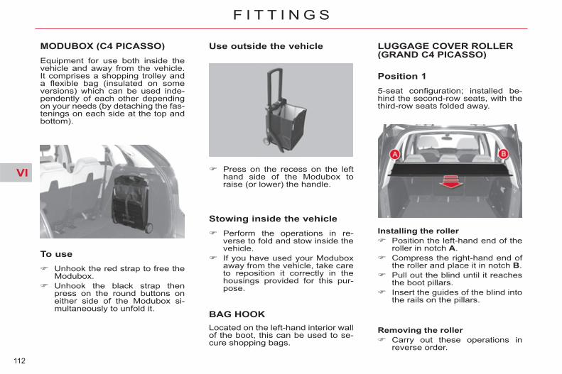
VI
112
F I T T I N G S
MODUBOX (C4 PICASSO) Equipment for use both inside the vehicle and away from the vehicle. It comprises a shopping trolley and a fl exible bag (insulated on some versions) which can be used inde-pendently of each other depending on your needs (by detaching the fas-tenings on each side at the top and bottom).
To use Unhook the red strap to free the
Modubox. Unhook the black strap then
press on the round buttons on either side of the Modubox si-multaneously to unfold it.
Use outside the vehicle
Stowing inside the vehicle Perform the operations in re-
verse to fold and stow inside the vehicle.
If you have used your Modubox away from the vehicle, take care to reposition it correctly in the housings provided for this pur-pose.
BAG HOOK
LUGGAGE COVER ROLLER(GRAND C4 PICASSO)
Position 1 5-seat confi guration; installed be-hind the second-row seats, with the third-row seats folded away.
Press on the recess on the left hand side of the Modubox to raise (or lower) the handle.
Located on the left-hand interior wall of the boot, this can be used to se-cure shopping bags.
Installing the roller Position the left-hand end of the
roller in notch A . Compress the right-hand end of
the roller and place it in notch B . Pull out the blind until it reaches
the boot pillars. Insert the guides of the blind into
the rails on the pillars.
Removing the roller Carry out these operations in
reverse order.

VI
113
F I T T I N G S
The roller has a moving fl ap to avoid interference with the second-row passengers when the seats are in the "reclined" position.
Engage the lug on the left of the roller in notch C .
Pass the right-hand end above the third-row armrest.
Engage the lug in notch D . Pull the seat belt(s) so that they
reel out without locking. Pull out the blind and engage
the guides into the rails on the pillars.
Lock the seat(s) in position.
Installing the roller Reel in the blind, then remove
the roller from its initial position. Position the roller, with the blind
pull bar uppermost, fl ap down-ward.
Fold the concertina boards.
Removing the roller Push the fl ap towards the seat
backrest. Lift the concertina board by tak-
ing it at the side, then position it vertically.
Release the seat by pulling the strap E .
Push the backrest towards the front. Proceed in reverse order to in-
stalling.
Position 3 7-seat confi guration; stowed behind the third row seats when these are folded away.
Installing the roller Fold the concertina boards. Position the roller, with the blind
pull bar uppermost, fl ap down-ward.
Engage the lug on the left of the roller in notch C .
Pass the right-hand end above the third-row armrest.
Engage the lug in notch D .
Removing the roller Proceed in reverse order to in-
stalling.
Position 2 7-seat confi guration; installed be-hind the third-row seats when these are folded away. This position con-ceals objects stowed in the boot from outside view.
The roller can only be stored when the seats are folded away. You can position the concertina board vertically to lodge a bulky ob-ject in the boot well.

VI
114
F I T T I N G S
CARGO NET(GRAND C4 PICASSO)
This enables you to maximise the vehicle’s loadspace. It retains objects, preventing them from sliding towards the front of the passenger compartment. You insert it under the luggage-cover roller securing it on the third-row side mouldings.
Position 1 5-seat confi guration: installed behind the second row.
Installing the roller Remove the protective covers
located under the blind roller notches.
Position the roller under that of the luggage-cover blind.
Raise the fl ap on the blind, posi-tioning it on top of the blind.
Deploy the net, passing it be-tween the rollers and the seats.
Pull the net upwards. Anchor it to the roof by means of
the fi xing points (after you have removed their covers).
Removing the roller Carry out these operations in re-
verse order.
Position 2 2-seat confi guration; installed be-hind the fi rst row.
Removing the roller Carry out these operations in re-
verse order.
Installing the roller With the second-row seats fold-
ed away, remove the covers of the Isofi x mounting points locat-ed on the seat backrests.
Secure the roller on the Isofi x mounting points.
Deploy the net and pull it up-wards.
Anchor it to the roof by means of the fi xing points (after you have removed their covers).

VI
115
F I T T I N G S
LUGGAGE ANCHORING RINGS (C4 PICASSO)
There are 4 anchoring rings in the boot to enable you to secure your luggage: - 1, 2, 3 and 4 on the boot fl oor.
LUGGAGE ANCHORINGRINGS (GRAND C4 PICASSO)
There are 4 anchoring rings in the boot to enable you to secure your luggage: - 1, 2, 3 and 4 on the boot fl oor.
For reasons of safety in the event of sudden braking, it is recommended that you place heavy objects on the fl oor as:m! close as possible to the backrests of the second-row seats.
LUGGAGE RETAINING NET (GRAND C4 PICASSO) Attached to the luggage anchoring rings, it allows objects to be held on the boot fl oor.

VI
116
F I T T I N G S
TORCH
This is a portable lamp, fi tted in the boot wall, which can be used to illu-minate the boot or as a torch.
Grand C4 Picasso
C4 Picasso
Boot lamp The boot lamp A comes on automat-ically when the boot is opened and switches off automatically when the boot is closed. Various lighting durations are avail-able: - ignition off, approximately ten minutes, - in energy economy mode, approxi-
mately thirty seconds, - engine running, no limit.
Operation of the torch This torch operates with NiMH re-chargeable batteries. It has a battery life of approximately 45 minutes and recharges while you are driving.
Extract the torch from its location pulling it upwards, as indicated by the arrow.
Press the switch B , located on the back, to switch the torch on or off.
Unfold the support C , located on the back, to set down and raise the torch; for example, when changing a wheel.
Stowing the torch Put the torch back in place in its
location, starting at the bottom. If you have forgotten to switch off
the torch, this switches it off auto-matically.
Observe the polarities when fi tting the batteries. Never replace the rechargeable batteries with normal single-use batteries. For replacement of the batteries, see the "Practical information - Changing a bulb" section.
It the torch is not engaged correct-ly, it may not charge and may not come on when the boot is opened.
Using the torch

VII
117
C H I L D S A F E T Y
* The rules for carrying children are specifi c to each country. Refer to the current legislation in your country.
GENERAL POINTS RELATINGTO CHILD SEATS Although one of CITROËN's main criteria when designing your vehicle, the safety of your children also de-pends on you. For maximum safety, please observe the following recommendations: - in accordance with European
regulations, all children under the age of 12 or less than one and a half metres tall must travel in approved child seats suited to their weight , on seats fi tted with a seat belt or ISOFIX mountings * ,
- statistically, the safest seats in your vehicle for carrying chil-dren are the rear seats,
- a child weighing less than 9 kg must travel in the "rearwards-facing" position both in the front and in the rear.
CITROËN recommends that chil-dren should travel in the rear seats of your vehicle: - "rearwards-facing" up to the
age of 2, - "forwards-facing" over the
age of 2.
CHILD SEAT IN THE FRONT
"Rearwards-facing" When a "rearwards-facing" child seat is installed on the front passenger seat , it is essential that the passenger airbag is deactivated. Otherwise, the child would risk being seriously in-jured or killed if the airbag were to infl ate .
Intermediate longitudinal position
"Forwards-facing" When a "forwards-facing" child seat is installed on the front passenger seat , adjust the vehicle's seat to the intermediate longitudinal position with the seat back upright and leave the passenger airbag activated.

VII
118
C H I L D S A F E T Y
Passenger airbag OFF Refer to the advice given on the la-bel present on both sides of the pas-senger's sun visor.
To assure the safety of your child, you must deactivate the passenger's front airbag when you install a child seat in the rearwards facing position on the front passenger's seat. Otherwise, there is a risk that the child could be seriously injured or killed if the airbag were deployed.

VII
119
C H I L D S A F E T Y
CHILD SEATS RECOMMENDED BY CITROËN CITROËN offers a complete range of recommended child seats which are secured using a three point seat belt :
Group 0+: from birth to 13 kg Groups 1, 2 and 3: from 9 to 36 kg
L1
"RÖMER Baby-Safe Plus" Installed in the rearwards-facing
position.
L2 "KIDDY Comfort Pro"
The impact shield must be used for carrying young children
(from 9 to 18 kg).
Groups 2 and 3: from 15 to 36 kg
L3 "RECARO Start''
L4 "KLIPPAN Optima"
From the age of 6 years (approximately 22 kg), the booster
is used on its own.
L5
"RÖMER KIDFIX" Can be fi tted to the vehicle's ISOFIX mountings.
The child is restrained by the seat belt.

VII
120
C H I L D S A F E T Y
* Applies only to the CITROËN Grand C4 Picasso.
LOCATIONS FOR CHILD SEATS SECURED WITH THE VEHICLE SEAT BELT In conformity with European law, this table tells you to what extent each of the seat positions in your vehicle may take a child seat that is secured with the vehicle seat belt and approved as Universal (a), according to the weight of the child and the position in the vehicle.
(a) Universal child seat: child seat which can be installed in all vehicles by means of the seat belt. (b) Group 0: from birth to 10 kg. Shell seats and "car cots" cannot be installed on the front passenger seat. (c) Consult the legislation in force in your country before installing your child on this seat. U : seat position suitable for the installation (in conjunction with the vehicle seat belt) of a universal rearwards-facing and/or
forwards-facing child seat.
For seats in groups 1, 2 and 3, check that the child seat is correctly secured on the backrest of the vehicle seat. If necessary, remove and stow the head restraint. To install a voluminous child seat in the 2nd or 3rd row, move the rear seat fully back so as to avoid interference with the front seat.
Seat position
Weight groups established by legislation
< 10 kg and < 13 kg (groups 0 (b) and 0+)
9 – 18 kg (group 1)
15 – 25 kg (group 2)
22 – 36 kg (group 3)
1st row Front passenger (c) U U U U
2nd row
Outer U U U U
Centre U U U U
3rd row * Outer U U U U
VII
121
C H I L D S A F E T Y
* According to country and current local legislation.
ADVICE ON CHILD SEATS
Installing a booster seat The chest part of the seat belt must be positioned on the child's shoul-der without touching the neck. Ensure that the lap part of the seat belt passes correctly over the child's thighs. CITROËN recommends the use of a booster seat which has a back, fi tted with a seat belt guide at shoulder level.
As a safety precaution, do not leave: - one or more children alone and
unsupervised in a vehicle, - a child or an animal in a vehicle
which is exposed to the sun, with the windows closed,
- the keys within reach of children inside the vehicle.
To prevent accidental opening of the doors, use the "Child lock". Take care not to open the rear win-dows by more than one third. To protect young children from the rays of the sun, fi t side blinds on the rear windows.
The incorrect installation of a child seat in a vehicle compromises the child's protection in the event of an accident. When installing a child seat using the seat belt, check that the seat belt is tightened correctly on the child seat and that it secures the child seat fi rmly on the seat of your vehicle. Remember to fasten the seat belts or the child seat harnesses keeping the slack in relation to the child's body to a minimum, even for short journeys. For optimum installation of the "for-wards-facing" child seat, ensure that the back of the child seat is in contact with the back of the vehicle's seat and that the head restraint does not cause any discomfort. If the head restraint has to be re-moved, ensure that it is stored or attached securely to prevent it from being thrown around the vehicle in the event of sharp braking.
Children under the age of 10 must not travel in the "forwards-facing" position on the front passenger seat, unless the rear seats are already oc-cupied by other children, cannot be used or are absent. Deactivate the passenger airbag * when a "rearwards-facing" child seat is installed on the front seat. Otherwise, the child would risk be-ing seriously injured or killed if the airbag were to infl ate.

VII
122
C H I L D S A F E T Y
"ISOFIX" MOUNTINGS Your vehicle has been approved in accordance with the latest ISOFIX regulation s. The three second row seats are fi tted with regulation ISOFIX mountings.
There are three rings for each seat:
- two rings A , located between the vehicle seat back and cushion, indicated by a label,
- a ring B , used to fi x the upper strap, referred to as the TOP TETHER , indicated by a label on a cover at the top of the seat back.
This ISOFIX mounting system pro-vides fast, reliable and safe fi tting of the child seat in your vehicle.
The incorrect installation of a child seat in a vehicle compromises the child's protection in the event of an accident.
For information on installing ISOFIX child seats in your vehicle, refer to the table showing the locations that can be used for ISOFIX child seats.
ISOFIX child seats are fi tted with two latches which are secured easily on the two rings A .
Some also have an upper strap which is attached to the ring B .
To attach this strap, remove the ve-hicle seat's head restraint and the cover at the top of the seat back. Then fi x the hook on the ring B and tighten the upper strap.
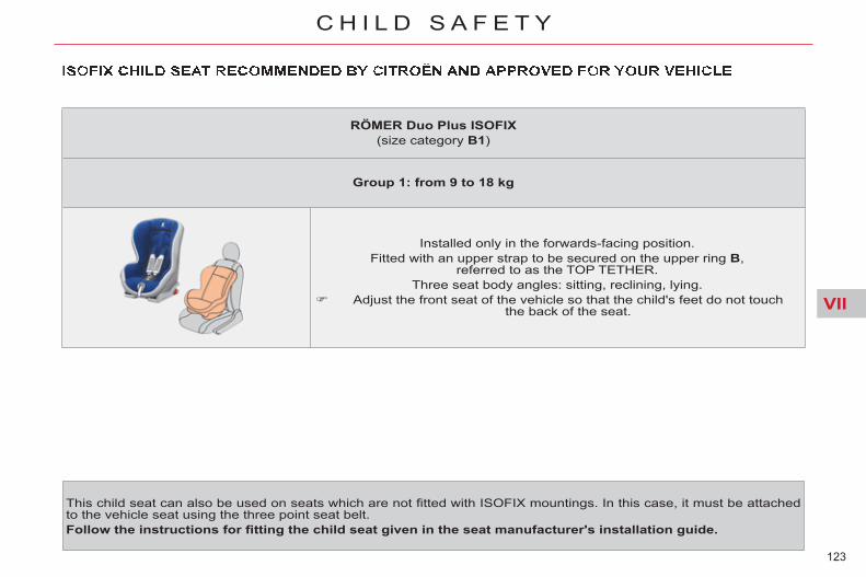
VII
123
C H I L D S A F E T Y
This child seat can also be used on seats which are not fi tted with ISOFIX mountings. In this case, it must be attached to the vehicle seat using the three point seat belt. Follow the instructions for fi tting the child seat given in the seat manufacturer's installation guide.
RÖMER Duo Plus ISOFIX (size category B1 )
Group 1: from 9 to 18 kg
Installed only in the forwards-facing position. Fitted with an upper strap to be secured on the upper ring B ,
referred to as the TOP TETHER. Three seat body angles: sitting, reclining, lying.
Adjust the front seat of the vehicle so that the child's feet do not touchthe back of the seat.
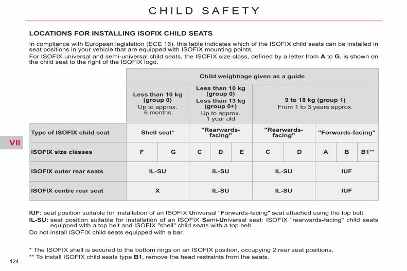
VII
124
C H I L D S A F E T Y
* The ISOFIX shell is secured to the bottom rings on an ISOFIX position, occupying 2 rear seat positions. ** To install ISOFIX child seats type B1 , remove the head restraints from the seats.
LOCATIONS FOR INSTALLING ISOFIX CHILD SEATS In compliance with European legislation (ECE 16), this table indicates which of the ISOFIX child seats can be installed in seat positions in your vehicle that are equipped with ISOFIX mounting points. For ISOFIX universal and semi-universal child seats, the ISOFIX size class, defi ned by a letter from A to G , is shown on the child seat to the right of the ISOFIX logo.
IUF : seat position suitable for installation of an I SOFIX U niversal " F orwards-facing" seat attached using the top belt. IL-SU : seat position suitable for installation of an I SOFIX S emi- U niversal seat: ISOFIX "rearwards-facing" child seats
equipped with a top belt and ISOFIX "shell" child seats with a top belt. Do not install ISOFIX child seats equipped with a bar.
Child weight/age given as a guide
Less than 10 kg (group 0)
Up to approx.6 months
Less than 10 kg (group 0)
Less than 13 kg (group 0+)
Up to approx.1 year old
9 to 18 kg (group 1) From 1 to 3 years approx.
Type of ISOFIX child seat Shell seat * "Rearwards-facing"
"Rearwards-facing" "Forwards-facing"
ISOFIX size classes F G C D E C D A B B1 **
ISOFIX outer rear seats IL-SU IL-SU IL-SU IUF
ISOFIX centre rear seat X IL-SU IL-SU IUF

VII
125
C H I L D S A F E T Y
MANUAL CHILD LOCK
Locking Using the ignition key, turn the
red control one eighth of a turn, following the instructions on the label.
Unlocking Using the ignition key, turn the
red control one eighth of a turn to return to the original position.
ELECTRIC CHILD LOCK
Mechanical system to prevent open-ing of the rear door using its interior control. The control is located on the edge of each rear door.
Remote control system to prevent opening of the rear doors using their interior controls and use of the rear electric windows.
Activation Press button A .
Deactivation Press button A again.
This system is independent of and in no circumstances takes the place of the central locking system. Check the status of the child lock each time you switch on the ignition. Always remove the key from the ignition when leaving the vehicle, even for a short time. In the event of a serious impact, the electric child lock is deactivated automatically to permit the exit of the rear passengers.
This warning lamp comes on temporarily on the instru-ment panel when the child lock is activated.
It also comes on when the ignition is switched on, then goes off approxi-mately ten seconds after the engine is started.
The control is located on the driver's door, with the electric window controls.

VIII
126
S A F E T Y
DIRECTION INDICATORS
Left: lower the lighting stalk beyond the point of resistance.
Right: raise the lighting stalk beyond the point of resistance.
HAZARD WARNING LAMPS A visual warning by means of the direction indicators to alert other road users to a vehicle breakdown, towing or accident.
Automatic operation of hazard warning lamps When braking in an emergency, depending on the deceleration, the hazard warning lamps come on automatically. They switch off automatically the fi rst time you accelerate. You can also switch them off by
pressing the button.
Horn Audible warning system to alert other road users to an imminent danger.
Selection of the left or right direc-tion indicators to signal a change of direction of the vehicle.
Press this button, the direction indicators fl ash.
They can operate with the ignition off.
Press at the lower part of the fi xed centred controls steering wheel.
Use the horn moderately and only in the following circumstances: - immediate danger, - approaching a location lacking
visibility.
"Motorway" function Press briefl y upwards or down-
wards, without going beyond the point of resistance; the direction indicators will fl ash 3 times.

VIII
127
S A F E T Y
TYRE UNDER-INFLATION DETECTION Sensors fi tted in each valve check the tyre pressure during driving and trigger a warning in the event of malfunction (speed above 12 mph (20 km/h)).
Under-infl ated tyre
The tyre under-infl ation detection system is an aid to driving which does not replace the vigilance or responsibility of the driver.
Puncture
The service warning lamp comes on in the instrument panel, accompanied by an audible signal and a mes-
sage on the multifunction screen lo-cating the wheel concerned. Check the tyre pressures as soon as possible. This check must be carried out when the tyres are cold.
The STOP warning lamp comes on in the instrument panel, accompanied by an audible signal and a mes-
sage on the multifunction screen lo-cating the wheel concerned. Stop immediately, avoiding any sud-den movement of the steering wheel and the brakes. Change the damaged wheel (punc-tured or very defl ated tyre), and have the tyre pressure checked as soon as possible.
Sensor(s) not detected or faulty
The service warning lamp comes on in the instrument panel, accompanied by an audible signal and a mes-
sage on the multifunction screen locating the wheel or wheels which are not detected or indicating a fault in the system. Have the faulty sensor(s) checked by a CITROËN dealer or a qualifi ed workshop.
All repairs and changing of tyres on a wheel fi tted with this system must be carried out by a CITROËN dealer or a qualifi ed workshop. If, when changing a tyre, you in-stall a wheel which is not detected by your vehicle (example: fi tting of snow tyres), you must have the system reinitialised by a CITROËN dealer or a qualifi ed workshop.
This system does not avoid the need to have the tyre pressures checked regularly (refer to the "Technical data - Identifi cation markings" section) to ensure that the optimum dynamic performance of the vehicle is maintained and prevent premature wear of the tyres, particularly in arduous driv-ing conditions (heavy load, high speed). The tyre pressures must be checked cold, at least once a month. Remember to check the pressure of the spare wheel. The tyre under-infl ation detection system may experience temporary interference due to electro-magnetic signals on a frequency close to that used by the system.
This message is also displayed when one of the wheels is away from the vehicle (being repaired) or when one or more wheels without a sensor are fi tted. The spare wheel is not fi tted with a sensor.

VIII
128
S A F E T Y
BRAKING ASSISTANCESYSTEMS Group of supplementary systems which help you to obtain optimum braking in complete safety in emer-gency situations: - anti-lock braking system (ABS), - electronic brake force distribu-
tion (EBFD), - emergency braking assistance
(EBA).
Anti-lock braking system and electronic brake force distribution Linked systems which improve the stability and manoeuvrability of your vehicle when braking, in particular on poor or slippery surfaces.
Activation The anti-lock braking system comes into operation automatically when there is a risk of wheel lock. Normal operation of the ABS may make itself felt by slight vibration of the brake pedal.
Operating fault
When braking in an emergency, press very fi rmly without releasing the pressure.
If this warning lamp comes on, accompanied by an au-dible signal and a message in the screen, it indicates a
malfunction of the anti-lock braking system which could result in loss of control of the vehicle when braking.
If this warning lamp comes on, together with the STOP and ABS warning lamps, accompanied by an audible
signal and a message in the screen, it indicates a malfunction of the elec-tronic brake force distribution which could result in loss of control of the vehicle when braking. You must stop as soon as it is safe to do so. In either case, contact a CITROËN dealer or a qualifi ed workshop.
When replacing wheels (tyres and rims), ensure that they conform to the manufacturer's recommenda-tions.
Emergency braking assistance System which, in an emergency, enables you to obtain the optimum braking pressure more quickly, thus reducing the stopping distance.
Activation It is triggered by the speed at which the brake pedal is pressed. The effect of this is a reduction in the resistance of the pedal and an increase in braking effi ciency.
When braking in an emergency, press fi rmly without releasing the pressure.

VIII
129
S A F E T Y
TRAJECTORY CONTROL SYSTEMS
Anti-slip regulation (ASR) and electronic stability programme (ESP) The anti-slip regulation (also known as Traction Control) optimises trac-tion to prevent skidding of the wheels, by acting on the brakes of the driving wheels and on the engine. The electronic stability programme acts on the brake of one or more wheels and on the engine to keep the vehicle on the trajectory required by the driver, within the limits of the laws of physics.
Deactivation In exceptional conditions (starting a vehicle which is bogged down, stuck in snow, on soft ground...), it may be advisable to deactivate the ASR and ESP systems, so that the wheels can move freely and regain grip.
Press the "ESP OFF" button, lo-cated in the centre of the dash-board.
If this warning lamp comes on in the instrument panel and the indicator lamp on the button comes on, this indi-cates that the ASR and ESP systems are deactivated.
This is indicated by fl ashing of this warning lamp in the instrument panel.
Activation These systems are activated auto-matically each time the vehicle is started. They come into operation in the event of a grip or trajectory problem.
Intelligent Traction Control system * Your vehicle has a system to help driving on snow. This automatic system continuously checks for situations of diffi cult sur-face adhesion that could make it dif-fi cult to move off or make progress on deep fresh snow or compacted snow. In these situations, the system takes over from the ASR system by opti-mising the amount of wheel slip to provide the best traction and trajec-tory control, even without snow tyres and with or without chains. In extremely severe conditions (snow on top of ice, sand, deep mud…), it can be useful to deactivate the ESP/ASR systems to allow a degree of wheel spin and so recover grip.
* Depending on engine type.

VIII
130
S A F E T Y
Reactivation These systems are reactivated au-tomatically each time the ignition is switched back on or from 30 mph (50 km/h). Press the "ESP OFF" button again
to reactivate them manually.
Operating fault
If this warning lamp comes on, accompanied by an au-dible signal and a message in the multifunction screen,
this indicates a malfunction of these systems. Have it checked by a CITROËN dealer or a qualifi ed workshop.
The ESP/ASR systems offer ex-ceptional safety in normal driving, but this should not encourage the driver to take extra risks or drive at high speed. The correct operation of these sys-tems depends on observation of the manufacturer's recommenda-tions regarding wheels (tyres and rims), braking components, elec-tronic components and assembly and repair procedures. After an impact, have these systems checked by a CITROËN dealer or a qualifi ed workshop.
EMERGENCY OR ASSISTANCE CALL
This system allows you to make an emergency or assistance call to the emergency services or to the dedi-cated CITROËN service. For more information on the use of this function, refer to the "Audio and telematics" section.
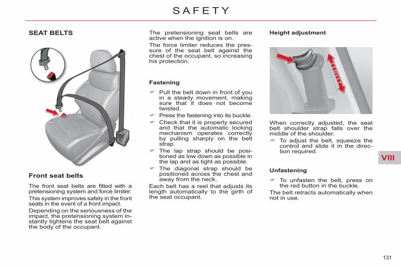
VIII
131
S A F E T Y
SEAT BELTS
Front seat belts The front seat belts are fi tted with a pretensioning system and force limiter. This system improves safety in the front seats in the event of a front impact. Depending on the seriousness of the impact, the pretensioning system in-stantly tightens the seat belt against the body of the occupant.
Fastening
Pull the belt down in front of you in a steady movement, making sure that it does not become twisted.
Press the fastening into its buckle. Check that it is properly secured
and that the automatic locking mechanism operates correctly by pulling sharply on the belt strap.
The lap strap should be posi-tioned as low down as possible in the lap and as tight as possible.
The diagonal strap should be positioned across the chest and away from the neck.
Each belt has a reel that adjusts its length automatically to the girth of the seat occupant.
Height adjustment The pretensioning seat belts are active when the ignition is on. The force limiter reduces the pres-sure of the seat belt against the chest of the occupant, so increasing his protection.
When correctly adjusted, the seat belt shoulder strap falls over the middle of the shoulder. To adjust the belt, squeeze the
control and slide it in the direc-tion required.
Unfastening
To unfasten the belt, press on the red button in the buckle.
The belt retracts automatically when not in use.
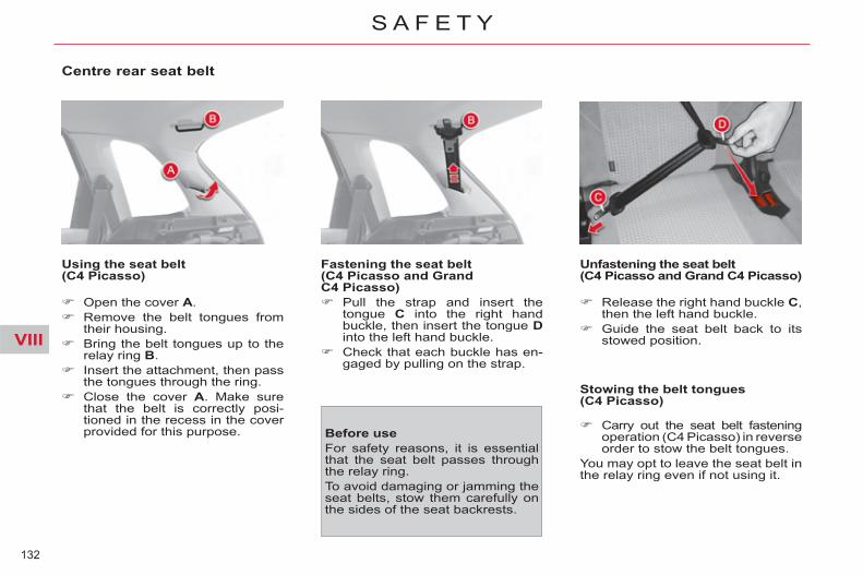
VIII
132
S A F E T Y
Centre rear seat belt
Using the seat belt (C4 Picasso)
Open the cover A . Remove the belt tongues from
their housing. Bring the belt tongues up to the
relay ring B . Insert the attachment, then pass
the tongues through the ring. Close the cover A . Make sure
that the belt is correctly posi-tioned in the recess in the cover provided for this purpose.
Fastening the seat belt (C4 Picasso and Grand C4 Picasso) Pull the strap and insert the
tongue C into the right hand buckle, then insert the tongue D into the left hand buckle.
Check that each buckle has en-gaged by pulling on the strap.
Unfastening the seat belt (C4 Picasso and Grand C4 Picasso)
Stowing the belt tongues (C4 Picasso)
Carry out the seat belt fastening operation (C4 Picasso) in reverse order to stow the belt tongues.
You may opt to leave the seat belt in the relay ring even if not using it.
Before use For safety reasons, it is essential that the seat belt passes through the relay ring. To avoid damaging or jamming the seat belts, stow them carefully on the sides of the seat backrests.
Release the right hand buckle C , then the left hand buckle.
Guide the seat belt back to its stowed position.

VIII
133
S A F E T Y
Third row rear seat belts (Grand C4 Picasso)
Instructions for use of the third row passenger seat belts
Take care to attach the third-row passenger seat belts securely to the rings provided for this purpose. Do not attach the belts to the lug-gage anchoring rings marked with a red cross, as shown in the illustration.
Stowing the tongue of the third-row seat belt
Secure the tongue in the location provided on the rear pillar trim.
The third-row passenger seat belts that are not being used can be stowed in order to free up loadspace and facilitate use of the luggage cover.
Before use: To avoid damaging or jamming the seat belts, stow them carefully on the sides of the seat backrests.

VIII
134
S A F E T Y
The driver must ensure that passen-gers use the seat belts correctly and that they are all restrained securely before setting off. Wherever you are seated in the ve-hicle, always fasten your seat belt, even for short journeys. Do not interchange the seat belt buckles as they will not fulfi l their role fully. The seat belts are fi tted with an in-ertia reel permitting automatic ad-justment of the length of the strap to your size. The seat belt is stowed automatically when not in use. Before and after use, ensure that the seat belt is reeled in correctly. The lower part of the strap must be positioned as low as possible on the pelvis. The upper part must be positioned in the hollow of the shoulder. The inertia reels are fi tted with an automatic locking device which comes into operation in the event of a collision, emergency braking or if the vehicle rolls over. You can re-lease the device by pulling fi rmly on the strap and releasing it so that it reels in slightly.
In order to be effective, a seat belt must: - be tightened as close to the body
as possible, - be pulled in front of you with a
smooth movement, checking that it does not twist,
- be used to restrain only one person, - not bear any trace of cuts or fraying, - not be converted or modifi ed to
avoid affecting its performance.
Recommendations for children Use a suitable child seat if the pas-senger is less than 12 years old or shorter than one and a half metres. Never use the same seat belt to se-cure more than one person. Never allow a child to travel on your lap.
In accordance with current safety regulations, for all repairs on your vehicle, go to a qualifi ed workshop with the skills and equipment need-ed, which a CITROËN dealer is able to provide. Have your seat belts checked reg-ularly by a CITROËN dealer or a qualifi ed workshop, particularly if the straps show signs of damage. Clean the seat belt straps with soapy water or a textile cleaning product, sold by CITROËN dealers. After folding or moving a seat or rear bench seat, ensure that the seat belt is positioned and reeled in correctly.
In the event of an impact Depending on the nature and se-riousness of the impact , the pre-tensioning device may be deployed before and independently of the airbags. Deployment of the preten-sioners is accompanied by a slight discharge of harmless smoke and a noise, due to the activation of the pyrotechnic cartridge incorporated in the system. In all cases, the airbag warning lamp comes on. Following an impact, have the seat belts system checked, and if neces-sary replaced, by a CITROËN dealer or a qualifi ed workshop.

VIII
135
S A F E T Y
AIRBAGS System designed to maximise the safety of the occupants (with the exception of the rear centre pas-senger) in the event of violent col-lisions. It supplements the action of the force-limiting seat belts. If a collision occurs, the electronic detectors record and analyse the front and side impacts sustained in the impact detection zones: - in the case of a serious impact,
the airbags are deployed instant-ly and protect the occupants of the vehicle (with the exception of the rear centre passenger); im-mediately after the impact, the airbags defl ate rapidly so that they do not hinder visibility or the exit of the occupants,
- in the case of a minor or rear im-pact or in certain roll-over con-ditions, the airbags will not be deployed; the seat belt alone is suffi cient to provide optimum protection in these situations.
The airbags do not operate when the ignition is switched off. This equipment will only operate once. If a second impact occurs (during the same or a subsequent ac-cident), the airbag will not operate.
Impact detection zones
A. Front impact zone. B. Side impact zone.
Deployment of the airbag(s) is ac-companied by a slight emission of harmless smoke and a noise, due to the activation of the pyrotechnic car-tridge incorporated in the system. This smoke is not harmful, but sen-sitive individuals may experience slight irritation. The noise of the detonation may result in a slight loss of hearing for a short time.
Front airbags System which protects the head and chest of the driver and front passen-ger in the event of a front impact. The driver's airbag is fi tted in the centre of the steering wheel; the front passenger's airbag is fi tted in the dashboard above the glove box.
Deployment The airbags are deployed simultane-ously, unless the passenger's front airbag is deactivated, in the event of a serious front impact applied to all or part of the front impact zone A , in the longitudinal centreline of the vehicle on a horizontal plane and di-rected from the front to the rear of the vehicle. The front airbag infl ates between the front occupant of the vehicle and the dashboard to cushion their forward movement.

VIII
136
S A F E T Y
Deactivation
This warning lamp comes on in the instrument panel when the ignition is on and until the airbag is reactivated.
To ensure the safety of your child, it is imperative that the passenger airbag is deactivated when you in-stall a "rearwards-facing" child seat on the front passenger seat. Otherwise, the child would risk be-ing seriously injured or killed if the airbag were deployed.
Activation When you remove the child seat, turn switch 1 to the "ON" position to reactivate the airbag and so ensure the safety of your front passenger in the event of an impact.
Operating fault
If this warning lamp comes on on the instrument panel, accompanied by an audible warning and a message in
the multifunction screen, contact a CITROËN dealer or a qualifi ed work-shop to have the system checked. The airbags may no longer be deployed in the event of a serious impact.
Only the front passenger's airbag can be deactivated: with the ignition off , insert the
key in the passenger airbag de-activation switch 1 ,
turn it to the "OFF" position, then, remove the key keeping
the switch in this position. If this warning lamp fl ashes, contact a CITROËN dealer or a qualifi ed workshop.
If both airbag warning lamps come on continuously, do not install a "rearwards-facing" child seat on the front passenger seat. Have it checked by a CITROËN dealer or a qualifi ed workshop.

VIII
137
S A F E T Y
* According to country.
Lateral airbags * System which protects the driver and front passenger in the event of a serious side impact in order to limit the risk of injury to the chest. Each lateral airbag is fi tted in the front seat back frame, on the door side.
Operation It is deployed unilaterally in the event of a serious side impact ap-plied to all or part of the side impact zone B , perpendicular to the longi-tudinal centreline of the vehicle on a horizontal plane and directed from the outside towards the inside of the vehicle. The lateral airbag infl ates between the front occupant of the vehicle and the corresponding door trim panel.
Impact detection zones
A. Front impact zone. B. Side impact zone.
Curtain airbags * System which protects the driver and passengers (with the exception of the rear centre passenger) in the event of a serious side impact in or-der to limit the risk of head injuries. Each curtain airbag is fi tted in the pillars and the upper part of the pas-senger compartment.
Operation It is deployed at the same time as the corresponding lateral airbag in the event of a serious side impact applied to all or part of the side im-pact zone B , perpendicular to the longitudinal centreline of the vehicle on a horizontal plane and directed from the outside towards the inside of the vehicle. The curtain airbag infl ates between the front or rear occupant of the ve-hicle and the windows.
In the event of a minor impact or bump on the side of the vehicle or if the vehicle rolls over, the airbag may not be deployed. The airbag is not deployed in the event of a rear or front collision.
If this warning lamp comes on in the instrument panel, accompanied by an audible signal and a message on
the multifunction screen, contact a CITROËN dealer or a qualifi ed work-shop to have the system checked. The airbags may no longer be deployed in the event of a serious impact.
Operating fault
* According to country.
VIII
138
S A F E T Y
For the airbags to be fully effective, observe the following safety rules:
Front airbags Do not drive holding the steering wheel by its spokes or resting your hands on the centre part of the wheel. Passengers must not place their feet on the dashboard. If possible, do not smoke as deploy-ment of the airbags can cause burns or the risk of injury from a cigarette or pipe. Never remove or pierce the steering wheel or hit it violently.
Lateral airbags Use only approved covers on the seats, compatible with the deployment the lateral airbags. For information on the range of seat covers suitable for your vehicle, you can contact a CITROËN dealer (see "Practical information - § Accessories"). Do not fi x or attach anything to the seat backs (clothing...). This could cause injury to the chest or arms if the lateral airbag is deployed. Do not sit with the upper part of the body any nearer to the door than necessary.
Curtain airbags Do not fi x or attach anything to the roof. This could cause injury to the head if the curtain airbag is de-ployed. If fi tted on your vehicle, do not re-move the grab handles installed on the roof, they play a part in securing the curtain airbags.
Sit in a normal upright position. Wear a correctly adjusted seat belt. Do not leave anything between the occupants and the airbags (a child, pet, object...). This could hamper the operation of the airbags or injure the occupants. After an accident or if the vehicle has been stolen or broken into, have the airbag systems checked. All work on the airbag system must be carried out by a CITROËN dealer or a qualifi ed workshop. Even if all of the precautions men-tioned are observed, a risk of injury or of minor burns to the head, chest or arms when an airbag is deployed cannot be ruled out. The bag infl ates almost instantly (within a few mil-liseconds) then defl ates within the same time discharging the hot gas via openings provided for this pur-pose.

IX
139
D R I V I N G
ELECTRIC PARKING BRAKE
The electric parking brake operates as follows: - automatic application/release Application is automatic when
the engine stops, release is au-tomatic on use of the accelerator (active by default).
- manual application/release Manual application/release of
the parking brake is possible by pulling control lever A while pressing the brake pedal.
Manual application With the vehicle stationary, to apply the parking brake whether the en-gine is running or not, pull control lever A .
Manual release With the ignition on or the engine running, to release the parking brake, press on the brake pedal, or the accelerator, pull then release control lever A .
- the warning lamp P in con-trol lever A and in the in-strument panel going off,
- the display of a message "Parking brake off" in the multi-function screen.
The application of the parking brake is confi rmed by:
- the illumination of the warn-ing lamp P in control lever A and in the instrument panel,
- the display of a message "Parking brake on" in the multi-function screen.
When the driver’s door is opened with the engine run-ning, a beep is heard and a
message displayed if the parking brake has not been applied. Before getting out of the vehicle, check that the warning lamp P is on fi xed in the instrument panel (not fl ashing).
The full application of the parking brake is confi rmed by:
If you pull control lever A without pressing the brake pedal, the parking brake will not be released and the "Foot on brake" warn-ing lamp will come on in the instrument panel.

IX
140
D R I V I N G
Automatic application, engine off With the vehicle stationary, the park-ing brake is automatically applied when the engine is switched off.
The application of the parking brake is confi rmed by:
- the illumination of warning lamp P in control lever A and in the instrument panel,
Automatic release The electric parking brake releases automatically and progressively when you press the accelerator: Manual gearbox (fi rst gear or
reverse gear engaged): press down fully on the clutch pedal then press on the accelerator pedal and move off.
Automatic gearbox : accelerate with the selector in position D , M or R .
Electronic gearbox : accelerate with the selector in position A , M or R .
Full release of the parking brake is confi rmed by:
- the warning lamp P in con-trol lever A and in the in-strument panel going off,
- the display of a message "Parking brake off" in the multifunction screen.
When stationary, with the engine running, do not press the acceler-ator pedal unnecessarily, as you may release the parking brake.
Maximum application If necessary, you can use maximum application of the parking brake. It is obtained by means of a long pull on control lever A , until you see the message "Parking brake on" and an audible signal is heard. Maximum application is essential: - when towing a caravan or a trail-
er, if the automatic functions are activated but you are applying the parking brake manually,
- when the gradient you are parked on is variable in its effect (e.g. on a ferry, in a lorry, during towing),
- when towing, when loaded or when parking on a gradient, turn the front wheels towards the pavement and engage a gear when you park,
- after a maximum application, the release time will be longer.
Before leaving the vehicle, check that warning lamp P in the instrument panel is on fi xed, not fl ashing.
Never leave a child alone inside the vehicle with the ignition on, as they could release the parking brake.
- the display of a message "Parking brake on" in the multi-function screen.
The normal operating sound will con-fi rm to you the application/release of the electric parking brake.

IX
141
D R I V I N G
To immobilise the vehicle, engine running To immobilise the vehicle when sta-tionary with the engine running, you must apply the parking brake manu-ally by pulling on control lever A .
The application of the parking brake is confi rmed by:
- the illumination of warning lamp P in control A and in the instrument panel,
- the display of a message "Parking brake on" in the multi-function screen.
When the driver’s door is opened, a beep is heard and a message dis-played if the parking brake has not been applied.
Before leaving the vehicle, check that warning lamp P in the instrument panel is on fi xed (not fl ashing).
Particular situations In certain situations (e.g. starting the engine), the parking brake can automatically alter its force. This is normal operation. To move your vehicle without start-ing the engine (towing, etc...), but with the ignition on , press the brake pedal and release the parking brake by pulling then releasing control lever A . The full release of the parking brake is confi rmed by the warning lamp P (red) in the instrument panel going off and the display of a message "Parking brake off" in the multifunc-tion screen. If the parking brake malfunctions while applied or if the battery runs fl at, an emergency release remains possible.
Activation/Deactivation of the automatic functions * The automatic application when the engine is switched off and the automatic release when you press the accelerator can be deactivated. Activation/deactivation is performed using the confi guration menu of the multifunction screen. To do so, se-lect "Vehicle parameters/Comfort/Automatic handbrake."
The deactivation of these functions is confi rmed by the lighting of this warning lamp in the instrument panel.
* According to country
With the automatic functions deac-tivated, the application and release of the parking brake are done manu-ally.

IX
142
D R I V I N G
Dynamic emergency braking
In the event of a failure of the vehi-cle’s main braking system or in an exceptional situation (e.g. driver tak-en ill, under instruction, etc) a con-tinuous pull on the control lever A will stop the vehicle. The electronic stability programme (ESP) provides stability during dy-namic emergency braking. If the dynamic emergency braking malfunctions, one of the following messages will be displayed in the multifunction screen: - "Parking brake faulty". - "Parking brake control faulty".
If a failure of the ESP sys-tem is signalled by the il-lumination of this warning lamp, then braking stability
is not guaranteed. In this event, sta-bility must be assured by the driver by repeating alternate "pull-release" actions on control lever A .
The dynamic emergency braking must only be used in exceptional circumstances.

IX
143
D R I V I N G
Emergency release In the event of a malfunction of the electric parking brake or the battery running fl at, an emergency mecha-nism can release the parking brake. Immobilise the vehicle, with the
engine running, by engaging fi rst gear (manual gearbox), posi-tion P (automatic gearbox) or M or R (6-speed electronic gearbox system).
Switch off the engine, but leave the ignition on.
If the vehicle cannot be immo-bilised, do not do anything and contact a CITROËN dealer or a qualifi ed workshop without delay.
Fetch the vehicle blocks E and the release tool F (handle) from the toolbox.
If on a gradient: chock the vehi-cle by placing the blocks in front of or behind the front wheels, on the falling side of the gradient.
If on level ground: chock the vehicle by placing the blocks in front of and behind one of the front wheels.
Slide the front left-hand seat back as far as possible.
Lift up the fl oor plug B on the carpet in front of the seat.
Pierce the tab C on the tube D with the release tool F .
Place the end of the handle F in the tube D .
Turn the release tool F clock-wise. For safety reasons , it is essential to continue turning the device as far as it will go. The parking brake is released.
Remove the release tool F and store it with the blocks E in the toolbox.
- The operation of the parking brake reinitialises itself when the ignition is switched off then on again. If the reinitialisation of the parking brake proves impos-sible, contact a CITROËN dealer or a qualifi ed workshop.
- The subsequent time required for application may be longer than during normal operation.
When the release tool F is engaged, do not operate the control lever or the ignition switch. Immobilisation of the vehicle is no longer assured once the manual emergency release has been used. The emergency release system cannot be used to apply the parking brake mechanically. Take care not to allow moisture or dust in the proximity of the plug.
For safety reasons, contact a CITROËN dealer or a qualifi ed workshop as soon as possible to have the plug replaced.

IX
144
D R I V I N G
SITUATION CONSEQUENCES
1
Electric parking brake fault and display of message " Parking brake faulty " and the fol-lowing warning lamps:
If the electric parking brake fault warning lamp and the service warning lamp come on, position the vehicle in a safe location (on fl at ground, with a gear engaged).
2
Display of message " Parking brake faulty " and the following warning lamps:
- The automatic functions are deactivated. - Hill start assist is not available. - The electric parking brake is only available manually.
3
Display of message " Parking brake faulty " and the following warning lamps:
- The manual release of the electric parking brake is not avail-able.
- Hill start assist is not available. - The automatic functions and manual application are still available.
If any of these instances arises, contact a CITROËN dealer or a qualifi ed workshop as soon as possible.
Operating faults

IX
145
D R I V I N G
SITUATION CONSEQUENCES
4
Display of message " Parking brake faulty " and the following warning lamps:
and/or fl ashing
- The automatic functions are deactivated. - Hill start assist is not available. To apply the electric parking brake: Immobilise the vehicle and switch off the ignition Pull the control lever for at least 5 seconds or until maximum
application. Switch on the ignition and check that the electric parking brake
warning lamps are on. - Application may take longer than in normal operation. - If warning lamp P fl ashes or if the warning lamps do not come
on when the ignition is switched on, this method does not work. Have it checked by a CITROËN dealer or a qualifi ed work-shop.
To release the electric parking brake: Switch on the ignition. Pull the control lever and hold it for approximately 3 seconds.
5
Display of message " Parking brake control faulty – auto parking brake activated " and the following warning lamps:
and/or fl ashing
- Only the functions for automatic application on switching off the engine and automatic release on acceleration are available.
- Manual application/release of the electric parking brake and dy-namic emergency braking are unavailable.
6
Battery fault - Lighting of the battery warning lamp makes it essential to stop the vehicle as soon as traffi c allows. Stop and immobilise your vehicle.
- Apply the electric parking brake before switching off the engine.

IX
146
D R I V I N G
HILL START ASSIST
System which holds your vehicle tem-porarily (approximately 2 seconds) when starting on a slope, the time it takes to move your foot from the brake pedal to the accelerator pedal. This function is only active when: - the vehicle is completely station-
ary, with your foot on the brake pedal,
- in particular conditions on a slope,
- with the driver’s door closed. The hill start assist cannot be deac-tivated.
Operation
Operating fault
If a malfunction of the system oc-curs, these warning lamps come on. Contact a CITROËN dealer or a qualifi ed workshop to have the sys-tem checked.
On an ascending slope, with the vehicle stationary, the vehicle is held for a brief moment when you release the brake pedal: - provided you are in fi rst gear or
neutral on a manual gearbox, - provided you are in position A
or M with the electronic gearbox system,
- provided you are in position D or M on an automatic gearbox.
On a descending slope, with the vehicle stationary and reverse gear engaged, the vehicle is held momentarily when you release the brake pedal.
Do not exit the vehicle while it is being held in the hill start assist phase. If you need to exit the ve-
hicle with the engine running, man-ually apply the parking brake and ensure that the warning lamp P (red) in the instrument panel is on (not fl ashing).

IX
147
D R I V I N G
5-SPEED MANUALGEARBOX
Starting the vehicle Check that the gear lever is in
neutral. Do not touch the accelerator. For Diesel engines: turn the
key to position M and wait until the pre-heating warning lamp switches off if it has come on.
Operate the starter, turning the key until the engine starts (no more than ten seconds).
In temperatures lower than 0°C, declutch while operating the starter to facilitate starting.
Only engage reverse gear when the vehicle is stationary with the engine at idle.
Engaging reverse gear Move the gear lever to the right
then back.

IX
148
D R I V I N G
GEAR SHIFT INDICATOR * System which reduces fuel con-sumption by advising the driver to change up on vehicles fi tted with a manual gearbox.
Operation The system intervenes only when driving economically. Depending on the driving situation and your vehicle's equipment, the system may advise you to skip one or more gears. You can follow this instruction without engaging the in-termediate gears. The gear recommended should not be considered compulsory. In fact, the confi guration of the road, the amount of traffi c and safety remain determining factors when choosing the best gear. Therefore, the driver remains responsible for deciding whether or not to follow the advice given by the system. This function cannot be deactivated.
* According to engine.
Example: - You are in third gear. - You press the accelerator pedal
moderately. - The system may suggest that
you engage a higher gear, if ap-propriate.
The information appears in the form of an arrow in the instrument panel screen. Depending on your vehicle's equip-ment, this arrow may be accompa-nied by the recommended gear.
In the case of driving which makes particular demands on the performance of the engine (fi rm pressure on
the accelerator pedal, for example, when overtaking...), the system will not recommend a gear change. The system never suggests: - engaging fi rst gear, - engaging reverse gear, - engaging a lower gear.

IX
149
D R I V I N G
Displays in the instrument panel
- The gear lever position is dis-played in the instrument panel, on the left on the A and C multi-function screens and on the right on NaviDrive and MyWay multi-function screens.
- A back-lit position grille associ-ated with the gear lever shows the position selected.
When the ignition is on, il-lumination of the service warning lamp, accompa-
nied by an audible signal and the message "Gearbox faulty" indicates a malfunction. Contact a CITROËN dealer or a qualifi ed workshop. For safety: position N can only be disen-
gaged if you are pressing the brake pedal.
if the gearbox is in position N but the gear lever position is dif-ferent, reposition the gear lever on N in order to be able to start.
Moving off
To start the engine, the gear le-ver must be in position N .
Press fi rmly on the brake pedal. Operate the starter. When the engine is running,
place the gear lever on R , A or M as desired.
In the instrument panel, check the position engaged.
Release the brake pedal and ac-celerate.
If the gear lever is not in position N , and/or if the brake pedal is not pressed, the corresponding warning lamp(s) are displayed and a mes-sage informs you that at least one of these two conditions is not met. In this case, the engine will not start, recommence the above procedure.
6-SPEED ELECTRONIC GEARBOX SYSTEM The 6-speed electronic gearbox of-fers a choice between the comfort of fully automatic operation or the driving pleasure of manual gear changing. You have a choice of two driving modes: - automatic mode for automatic con-
trol of the gears by the gearbox, - manual mode for sequential
changing of the gears by the driver.
Automated mode: gear lever 2 in position A .
Manual mode: gear lever 2 in po-sition M .
In automated mode, temporary man-ual operation is possible any time by using one of the paddles 1 .
Mode selection

IX
150
D R I V I N G
Automatic mode
Move the gear lever to A .
Manual mode
Pull the " + " paddle to change up a gear.
Pull the " - " paddle to change down a gear.
When the engine is running, before accelerating to move the vehicle, make sure that the position engaged on the
selector grille or in the instrument panel is either: R , A or M Do not leave the vehicle with the engine running in R , A or M .
Operation in automatic mode
Move the gear lever to position A . The warn-ing lamp A comes on in the instrument panel to confi rm the selection.
Reverse gear To engage reverse, the vehicle must be immobilised with your foot on the brake pedal.
Move the gear lever to R .
At low speeds, if reverse is selected, the N indicator fl ashes and the gear-box goes into neutral automatically. To engage reverse, put the gear le-ver in position N , then in position R .
Neutral
Move the gear lever to N .
If the vehicle is moving, do not select this position even momentarily.
Move the gear lever to M .
The gearbox then functions in auto-matic mode, without any action on your part. It constantly selects the gear that is best suited to the following condi-tions: - driving style, - road profi le, - optimum fuel consumption.
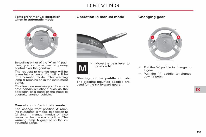
IX
151
D R I V I N G
Operation in manual mode
Move the gear lever to position M .
Steering mounted paddle controls The steering mounted paddles are used for the six forward gears.
Changing gear
Pull the " + " paddle to change up a gear.
Pull the " - " paddle to change down a gear.
By pulling either of the " + " or " - " pad-dles, you can exercise temporary control over the gearbox. The request to change gear will be taken into account. You will still be in automatic mode. The warning lamp A remains on in the instrument panel. This function enables you to antici-pate certain situations such as the approach of a bend or the need to overtake another vehicle.
Cancellation of automatic mode The change from position A (driv-ing in automatic mode) to position M (driving in manual mode) or vice versa can be made at any time. The warning lamp A goes off in the in-strument panel.
Temporary manual operation when in automatic mode

IX
152
D R I V I N G
Acceleration For optimum acceleration (e.g. to overtake another vehicle), simply press the pedal beyond the point of resistance at the end of its travel, by pressing down fi rmly.
Vehicle stationary, with the engine running In the event of a prolonged stop with the engine running, the gearbox changes automatically to neutral N .
Stopping the vehicle Before stopping the engine, you can choose: to leave the vehicle in neutral;
move the gear lever to position N . to leave the vehicle with a gear
engaged ( R , A or M ); place the gear lever in the chosen position prior to stopping the engine. In this case, the vehicle cannot be moved.
In all cases, it is essential to apply the parking brake. Check that the parking brake warning lamp is on in the instrument panel.
Do not use the accelera-tor to hold your vehicle on a gradient. Use either the brake pedal or the parking brake.
Before doing anything in the en-gine compartment, check that the gear lever is in neutral N .
The paddles cannot be used to se-lect neutral or reverse gear, or to exit reverse gear. - If the vehicle stops or reduces
speed (for example when ap-proaching a stop sign), the gear-box changes down automatically, to fi rst gear if needed.
- In manual mode, it is not neces-sary to release the accelerator completely during gear changes.
- A request to change gear is ac-cepted only if the engine speed permits it.
- For safety reasons, depending on the engine speed, a change down may be performed auto-matically.
In situations of high engine speeds (heavy accelera-tion), a change up will not occur unless the driver op-erates the paddle.

IX
153
D R I V I N G
The Stop & Start system puts the en-gine temporarily into standby - STOP mode - during stops in the traffi c (red lights, traffi c jams, or other...). The en-gine restarts automatically - START mode - as soon as you want to move off. The restart takes place instantly, quickly and silently. Perfect for urban use, the Stop & Start system reduces fuel consump-tion and exhaust emissions as well as the noise level when stationary.
Operation
Going into engine STOP mode
The "ECO" warning lamp comes on in the instrument panel and the engine goes into standby:
- with the electronic gearbox system , at speeds below 4 mph (6 km/h), press the brake pedal or put the gear lever in position N .
If your vehicle is fi tted with the sys-tem, a time counter calculates the sum of the periods in STOP mode during a journey. It rests itself to zero every time the ignition is switched on with the key.
Special cases: STOP mode not available
Never refuel with the en-gine in STOP mode; you must switch off the ignition with the key.
For your comfort, during parking maoeuvres, STOP mode is not available for a few seconds after coming out of reverse gear. STOP mode does not affect the functionality of the vehicle, such as for example, braking, power steer-ing...
STOP mode is not invoked when:
- the driver's door is open, - the driver's seat belt is not fas-
tened, - the vehicle has not exceeded
6 mph (10 km/h) since the last engine start using the key,
- the electric parking brake is ap-plied or being applied,
- the engine is needed to maintain a comfortable temperature in the passenger compartment,
- demisting is active, - some special conditions (battery
charge, engine temperature, braking assistance, ambient temperature...) where the engine is needed to assure control of a system.
In this case, the "ECO" warning lamp fl ashes for a few seconds then goes off. This operation is perfectly normal.

IX
154
D R I V I N G
Going into engine START mode Special cases: START invoked automatically
At any time, press the "ECO OFF" switch to deactivate the system. This is confi rmed by the switch warn-ing lamp coming on accompanied by a message in the screen.
Deactivation
Reactivation Press the "ECO OFF" switch again. The system is active again; this is confi rmed by the switch warning lamp going off and a message in the screen.
The "ECO" warning lamp goes off and the engine starts with the electronic gearbox system :
- gear lever in position A or M , re-lease the brake pedal,
- or gear lever in position N and the brake pedal released, move the gear lever to position A or M ,
- or engage reverse gear.
START mode is invoked au-tomatically when:
- the driver's door is open, - the driver's seat belt is not fas-
tened, - the speed of the vehicle exceeds
7 mph (11 km/h) with the elec-tronic gearbox system,
- the electric parking brake is be-ing applied,
- some special conditions (battery charge, engine temperature, braking assistance, ambient tem-perature...) where the engine is needed for control of a system.
In this case the "ECO" warning lamp fl ashes for a few seconds, then goes off. This operation is perfectly normal.
If the system has been deactivated in STOP mode, the engine restarts immediately.
The system is reactivated auto-matically at every new start using the key.

IX
155
D R I V I N G
In the event of a fault with the sys-tem, the "ECO OFF" switch warning lamp fl ashes then comes on con-tinuously. Have it checked by a CITROËN dealer or a qualifi ed workshop. In the event of a fault in STOP mode, the vehicle may stall. It is then nec-essary to switch off the ignition and start the engine again using the key.
Maintenance Operating fault
Before doing anything un-der the bonnet, deactivate the Stop & Start system to
avoid any risk of injury resulting from automatic operation of START mode.
This system requires a 12 V battery with a special specifi cation and tech-nology (reference numbers available from CITROËN dealers). Fitting a battery not listed by CITROËN introduces the risk of malfunction of the system. To charge the battery, use a 12 V charger and observe the polarity.
The Stop & Start system makes use of advanced technology. For any work
on the system go to a qualifi ed workshop with the skills and equip-ment required, which a CITROËN dealer is able to provide.

IX
156
D R I V I N G
AUTOMATIC GEARBOX
Automatic gearbox which offers a choice between the ease of fully automatic operation or the driving pleasure of manual gear changing. There is a choice of two driving modes: - automatic operation for elec-
tronic control of the gears by the gearbox,
- manual operation for sequen-tial changing of the gears by the driver.
Automatic mode: gear lever 1 in position D ,
Manual mode: gear lever 1 in po-sition M .
The position of the gear lever is dis-played in the instrument panel, on the left on the A and C multifunc-tion screens and on the right in the MyWay and NaviDrive multifunction screens. A grille associated with the gear le-ver also allows you to see the se-lected position.
Position P can only be dis-engaged if pressing the brake pedal. On opening a door, there is
an audible signal if the gear lever is not in position P . In all circumstances, ensure that the gear lever is in position P be-fore leaving your vehicle. If P is displayed in the instrument panel but the position of the gear lever is different, reposition the gear lever on P so that you can start the vehicle. Never press the brake and ac-celerator pedals simultaneously. Braking and acceleration should be done only with the right foot. Pressing both pedals simultane-ously introduces a risk of damage to the gearbox.
Displays in the instrument panel
Multifunction screen A or C MyWay or NaviDrive multifunction screen
Mode selection

IX
157
D R I V I N G
To start the engine, press the brake pedal and place the gear lever in position P .
Operate the starter. When the engine is running,
place the gear lever on R , D or M as required.
Check, in the instrument panel, the position engaged.
Release the brake pedal and ac-celerate.
If the gear lever is not in position P , a message "Place automatic gearbox in position P " is displayed in the mul-tifunction screen. It is accompanied by an audible signal and fl ashing of P in the instrument panel.
Moving off To avoid any difference between the position of the gear lever and the true position of the gearbox, always come out of position P with the igni-tion on and your foot on the brake.
When this warning lamp comes on in the instru-ment panel, press the brake pedal to disen-gage the gear lever from position P .
Park
To select position P, move the gear lever back to the highest position (towards R ), then push it forwards and then to the left.
To exit position P , move the gear lever to the right and then to the position you want.
Only engage this position when the vehicle is completely sta-tionary. In this position, the front wheels are locked. Make sure that the gear lever is correctly positioned.
Reverse gear
Neutral
Only engage this position when the vehicle is station-ary. To prevent snatching, do not accelerate too soon after selection.
Never select position N if the vehicle is moving.
Never select positions P or R unless the vehicle is sta-tionary.
If, while the vehicle is moving, po-sition N is engaged inadvertently, allow the engine to idle before en-gaging position D or M .
This position of the gear le-ver is used to prevent the vehicle from moving when you are stationary.
Foot on the brake
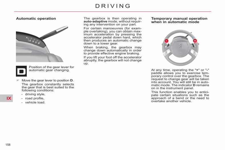
IX
158
D R I V I N G
Automatic operation
Position of the gear lever for automatic gear changing.
The gearbox is then operating in auto-adaptive mode, without requir-ing any intervention on your part. For certain manoeuvres (for exam-ple overtaking), you can obtain max-imum acceleration by pressing the accelerator pedal down hard, which then produces an automatic change down to a lower gear. When braking, the gearbox may change down automatically in order to provide effective engine braking. If you lift your foot off the accelerator abruptly, the gearbox will not change up.
Temporary manual operation when in automatic mode
Move the gear lever to position D . The gearbox constantly selects
the gear that is best suited to the following conditions: - driving style, - road profi le, - vehicle load.
At any time, operating the " + " or " - " paddle allows you to exercise tem-porary control over the gearbox. The request to change gear will be taken into account. You will still be in auto-matic mode. The indicator D remains on in the instrument panel. This function enables you to antici-pate certain situations such as the approach of a bend or the need to overtake another vehicle.

IX
159
D R I V I N G
Manual operation
Position of the gear lever for manual gear changing.
Move the gear lever to position M .
Pull the " + " paddle to change up a gear.
Pull the " - " paddle to change down a gear.
- If the vehicle stops or reduces speed (for example when ap-proaching a stop sign), the gear-box changes down automatically to fi rst gear.
- In manual mode, it is not neces-sary to release the accelerator during gear changes.
- A request to change gear is ac-cepted only if the engine speed permits it.
- For safety reasons, depending on the engine speed, a change up or down may be performed automatically.
- It is possible at any time to change mode, by moving the gear lever from position D to po-sition M or vice versa.
Flashing of the indicator for the position requested sig-nals that this position is not yet obtained.
If the indicator is on fi xed, the posi-tion is confi rmed. Display of a dash in the rev counter indicates a malfunction. Contact a CITROËN dealer or a qualifi ed workshop. Illumination of the service warning lamp accompanied by a message and an audible signal indicates an operating fault. In this case: - a marked snatching may be felt
when selecting R for reverse gear,
- the gearbox is locked in one gear,
- do not exceed a speed of 60 mph (approximately 100 km/h).
Have it checked by a CITROËN dealer or a qualifi ed workshop.

IX
160
D R I V I N G
FIXED CENTRED CONTROLS STEERING WHEEL
Cruise control/speed limiter and parking sensor controls 1. Activation of the parking
sensors function. 2. Selection of cruise control or
speed limiter. 3. Activation/Deactivation of speed
limiter. Deactivation/Reactivation of
cruise control. 4. Increase speed/Activation of
cruise control. 5. Decrease speed/Activation of
cruise control.
Audio system controls A. Volume decrease. B. Volume increase. C. Search of higher frequencies. D. Scrolling pre-set stations. E. Mute. (see "Audio and Telematics" section)

IX
161
D R I V I N G
Optional function controls 1. Call/Hang up the telephone (see
"Audio and Telematics" section). 2. Rheostat for dashboard lighting. 3. Start of voice recognition (see
"Audio and Telematics" section). 4. Personalisation button:
- courtesy lamp on/off or - diagnostics Press this button for more than
two seconds to display the per-sonalisation menu.
5. Air recirculation.
Multifunction screen controls A. Selection of the type of informa-
tion to be displayed on the right of the screen (radio, trip comput-er, navigation/guidance…).
For the multifunction screen A, choice of activation/deactivation of functions and setting choices.
B. Access to the "Main Menu" * . C. Confi rmation of the function cho-
sen or of the value modifi ed. Call/Hang up (see "Audio and
Telematics" section). D. Scrolling in the multifunction
screen. E. Cancellation of the current op-
eration or return to the previous display.
* To comply with legislation in certain coun-tries, the "Menu" control may be deacti-vated while the vehicle is in motion.

IX
162
D R I V I N G
SPEED LIMITER
System which prevents the vehi-cle from exceeding the speed pro-grammed by the driver. Once the limit speed has been reached, the accelerator pedal no longer has any effect. The speed limiter is switched on manually: a speed of at least 20 mph (approximately 30 km/h) must be pro-grammed.
The speed limiter controls are locat-ed on the left-hand side of the steer-ing wheel.
The programmed information is grouped together in zone A of the instrument panel screen.
Steering mounted controls
Displays in the instrument panel
Programming Rotate the control 1 to the "LIM" po-sition.
With the engine running, you can adjust the memorised maximum speed , by means of short or long presses on: button 4 to increase the memo-
rised maximum speed, button 2 to decrease the memo-
rised maximum speed. Successive presses will modify the maximum speed in steps of 1 mph (1 km/h) and a sustained press in steps of 3 mph (5 km/h).
Activation When the desired maximum speed is displayed, press button 3 so that the limitation is activated.
On selection of the function, the previous memorised speed and the information "OFF" are displayed in the in-strument panel.
The information "OFF" then disappears from the instrument panel screen.
While the function is active, press-ing the accelerator pedal will not en-able the programmed speed to be exceeded, except if you press the pedal hard down to beyond the end-of-travel switch. The speed of your vehicle may vary slightly in relation to that memo-rised.
The speed limiter cannot, in any circum-stances, take the place of the obser-vance of speed limits or of the vigilance and responsibility of the driver.

IX
163
D R I V I N G
Deactivation Press on button 3 .
This action causes the information "OFF" to appear on the instru-ment panel screen.
This action does not cancel the memorised maximum speed which remains displayed in zone A of the instrument panel.
Override of the programmed speed The accelerator pedal is equipped with an end-of-travel switch. If you action this switch by pressing the pedal hard down, you can exceed the memorised maximum speed at any time. During the time the speed is be-ing exceeded, the displayed speed fl ashes. You have only to release the ac-celerator pedal to return below the maximum speed and render the function active again.
Return to normal driving
By moving the control 1 from po-sition "LIM" to position 0 .
By the engine stopping. The speed previously chosen is still memorised.
Operating fault If there is a speed limiter malfunc-tion, a message will display accom-panied by an audible signal and lighting of the service warning lamp. Have it checked by a CITROËN dealer or a qualifi ed workshop.
If during the operation of the speed limiter, the system is unable to keep within the maximum speed (for ex-ample on a steep descent or under heavy acceleration) then the speed fl ashes. Adapt your speed as neces-sary. The function will re-engage when your speed returns below the de-sired maximum speed.
On a steep downhill gradi-ent or on sharp accelera-tion, the speed limiter will
not be able to prevent the vehicle from exceeding the programmed speed. Use of fl oor mats that are not ap-proved by CITROËN may hinder access to the accelerator pedal and thus interfere with the function-ing of the speed limiter. To avoid any risk of interfering with the pedals: - check that the fl oor mat is cor-
rectly positioned, - never use more than one fl oor
mat.

IX
164
D R I V I N G
CRUISE CONTROL
System which automatically main-tains the vehicle speed programmed by the driver, without any action on the accelerator pedal. The cruise control is switched on manually: the vehicle speed must be at least 25 mph (approximately 40 km/h) and you must engage: - fourth gear on a manual gear-
box, - second gear, in manual mode,
on an electronic or automatic gearbox,
- position A on an electronic gear-box or D on an automatic gearbox.
Steering mounted controls
The cruise control switches are lo-cated on the left-hand side of the steering wheel.
The programmed information is grouped together in zone A of the instrument panel screen.
Displays in the instrument panel
Activation
You can then release the accelera-tor pedal. The vehicle will automati-cally keep to the speed chosen. The speed of your vehicle may vary slightly in relation to that memo-rised. You can adjust the memorised speed in the instrument panel screen by pressing: button 4 to increase the speed, button 2 to decrease the speed. Successive presses modify the cruise speed in steps of 1 mph (1 km/h) and a sustained press in steps of 3 mph (5 km/h).
Deactivation Either by pressing the brake or
the clutch pedal. Or by pressing button 3 . Or if either the ESP or the ASR
system is active. The cruise control is not active if the gear lever is in neutral.
On selection of the function via control 1, no cruise speed has yet been memorised.
Programming Rotate the control 1 to the "REG" position.
Once the desired speed has been reached using the accelerator, press button 2 or 4 . The cruise speed is then memorised. It is displayed in zone A of the instrument panel.
These actions cause the information "OFF" to appear in the instru-ment panel screen. These actions do not cancel the cruise speed which remains displayed in the instrument panel.
The cruise control cannot, in any cir-cumstances, take the place of the observance of speed limits or of the vig-ilance and responsibility of the driver.

IX
165
D R I V I N G
Reactivation By recall of the memorised
speed After a disengagement, press on
button 3 . Your vehicle automati-cally returns to the memorised cruise speed which is displayed in zone A .
If the memorised cruise speed is higher than the current speed, the vehicle will accelerate to reach the former.
By selection of the current speed
Press on button 2 or 4 once the desired speed has been reached. The information "OFF" will then disappear from the instrument panel display.
Overriding the programmed speed During the operation of cruise con-trol, it is always possible to use the accelerator to go faster than the cruise speed (for example to over-take another vehicle). The speed displayed in zone A fl ashes. You have only to release the accel-erator pedal to return to the cruise speed.
If during the operation of cruise control, the system is unable to keep within the memorised speed (for example on a steep descent), then the speed fl ashes. Adapt your speed as necessary.
Return to normal driving
Operating fault If there is a malfunction, a message will display accompanied by an au-dible signal and lighting of the ser-vice warning lamp. Have it it checked by a CITROËN dealer or a qualifi ed workshop.
Cruise control should only be used when the driving conditions allow you to drive at a constant speed. Do not use it in heavy traf-
fi c, or on dangerous or slippery roads. The driver must remain attentive and in full control of his vehicle. You are recommended to always keep your feet within range of the pedals. To avoid any risk of interfering with the pedals: - check that the fl oor mat is cor-
rectly positioned, - never use more than one fl oor
mat.
By an action on the control 1 from position "REG" to position 0 .
By the engine stopping. The cruise speed previously
chosen is no longer memorised.

IX
166
D R I V I N G
PARKING SPACE SENSORS
After measuring the parking space available between two vehicles or obstacles, this system gives you in-formation on: - the possibility of fi tting into a free
space, depending on the dimen-sions of your vehicle and the dis-tances needed for manoeuvring,
- the level of diffi culty of the ma-noeuvre to be performed.
The system does not measure spaces which are clearly much smaller or larger than the size of the vehicle.
Displays in the instrument panel
The parking space sensor function warning lamp can have three different states:
- off: the function is not selected, - on fi xed: the function is selected
but the conditions for measure-ment are not yet met (direction indicator not operating, speed too high) or the measurement phase has ended,
- fl ashing: measurement is in progress or the message is be-ing displayed.
You can activate the "parking space sensor" function by pressing but-ton A. The fi xed illumination of the warning lamp indicates that the function is selected.

IX
167
D R I V I N G
Operation You have identifi ed a parking space: Press button A to activate the
function. Activate the direction indicator
on the side where the space is to be measured.
During the measuring, go for-ward the length of the space, at a speed less than 12 mph (ap-proximately 20 km/h), to prepare for your manoeuvre.
The system then measures the size of the space.
The system informs you of the level of diffi culty of the manoeu-vre via a message in the multi-function screen accompanied by an audible signal.
Parking possible
Parking diffi cult
Parking not advised
The function displays the following types of message:
The function deactivates itself auto-matically: - when you engage reverse gear, - when you switch off the ignition, - fi ve minutes after activation of
the function or after the last mea-surement operation,
- if the vehicle speed exceeds the threshold of 45 mph (approxi-mately 70 km/h) for one minute.
If there is a malfunction, have the system checked by a CITROËN dealer or a qualifi ed workshop.
If the lateral distance between your vehicle and the parking space is too great, the system may not operate.
- The function remains available after each measurement and so can measure a number of places successively.
- In bad weather or in winter, en-sure that the sensors are not cov-ered by dirt, or by ice or snow.
- The parking space sensor func-tion deactivates the front parking sensors during the space mea-suring phase when you are in forward gear.

IX
168
D R I V I N G
LANE DEPARTURE WARNING SYSTEM System which detects the involun-tary crossing of longitudinal traffi c lane markings on the ground (solid or broken line). Sensors, fi tted below the front bum-per, trigger a warning if the vehicle drifts over a lane marking (speed higher than 50 mph (80 km/h)).
This system is particularly useful on motorways and main roads.
Activation Press this button, the indicator
lamp comes on.
Deactivation Press this button again, the indi-
cator lamp goes off. The status of the system remains in the memory when the ignition is switched off. Detection You are warned by the vibration of the driver's seat cushion: - on the right-hand side, if the
marking on the ground has been crossed on the right,
- on the left-hand side, if the marking on the ground has been crossed on the left.
No warning is transmitted while the direction indicator is active and for approximately 20 seconds after the direction indicator is switched off. A warning may be transmitted if a direction marking (e.g. arrow) or non-standard marking (e.g. graffi ti) is crossed.
Operating fault In the event of a malfunction, the service warning lamp comes on, ac-companied by an audible signal and a message in the screen. Contact a CITROËN dealer or a qualifi ed workshop.
The lane departure warning sys-tem cannot, in any circumstances, replace the need for vigilance and responsibility on the part of the driver.
The detection may be impeded: - if the sensors are dirty (mud,
snow...), - if the markings on the ground
are worn, - if there is little contrast between
the markings on the ground and the road surface.

IX
169
D R I V I N G
PARKING SENSORS This system indicates the proximity of an obstacle (person, vehicle, tree, gate, etc.) which comes within the fi eld of detection of sensors located in the bumper. Certain types of obstacle (stake, roadworks cone, etc.) detected ini-tially will no longer be detected at the end of the manoeuvre due to the presence of blind spots.
Visual assistance This supplements the audible signal by displaying bars in the multifunc-tion screen which move progressive-ly nearer to the vehicle. When the obstacle is near, the "Danger" sym-bol is also displayed in the screen.
Audible assistance The proximity information is given by an intermittent audible signal, the frequency of which increases as the vehicle approaches the obstacle. The sound emitted by the speaker (right or left) indicates the side on which the obstacle is located. When the distance between the vehicle and the obstacle becomes less than approximately thirty centi-metres, the audible signal becomes continuous.
This function cannot, in any circum-stances, take the place of the vigi-lance and responsibility of the driver.
Rear parking sensors
The system is switched on by en-gaging reverse gear. This is accom-panied by an audible signal. The system is switched off when you exit reverse gear.

IX
170
D R I V I N G
Front parking sensors In addition to the rear parking sen-sors, the front parking sensors are triggered when an obstacle is detect-ed in front and the speed of the ve-hicle is still below 6 mph (10 km/h). The front parking sensors are inter-rupted if the vehicle stops for more than three seconds in forward gear, if no further obstacles are detected or when the speed of the vehicle ex-ceeds 6 mph (10 km/h).
The sound emitted by the speaker (front or rear) indicates whether the obstacle is in front or behind.
Deactivation/Activation of the front and rear parking sensors The function is deactivated by press-ing this button. The indicator lamp in the button comes on. Pressing this button again reacti-vates the function. The indicator lamp in the button goes off.
The function will be deactivated au-tomatically if a trailer is being towed or a bicycle carrier is fi tted (vehicle fi tted with a towbar or bicycle car-rier recommended by CITROËN).
Operating fault
In the event of a malfunction of the system, when reverse gear is engaged this warn-ing lamp is displayed in the
instrument panel and/or a message appears in the screen, accompanied by an audible signal (short beep). Contact a CITROËN dealer or a qualifi ed workshop.
In bad weather or in winter, ensure that the sensors are not covered with mud, ice or snow. When re-verse gear is engaged, an audible signal (long beep) indicates that the sensors may be dirty. When the vehicle is moving at a speed below 6 mph (10 km/h), cer-tain sound sources (motorcycle, lorry, pneumatic drill, etc.) may trig-ger the audible signals of the park-ing sensor system.
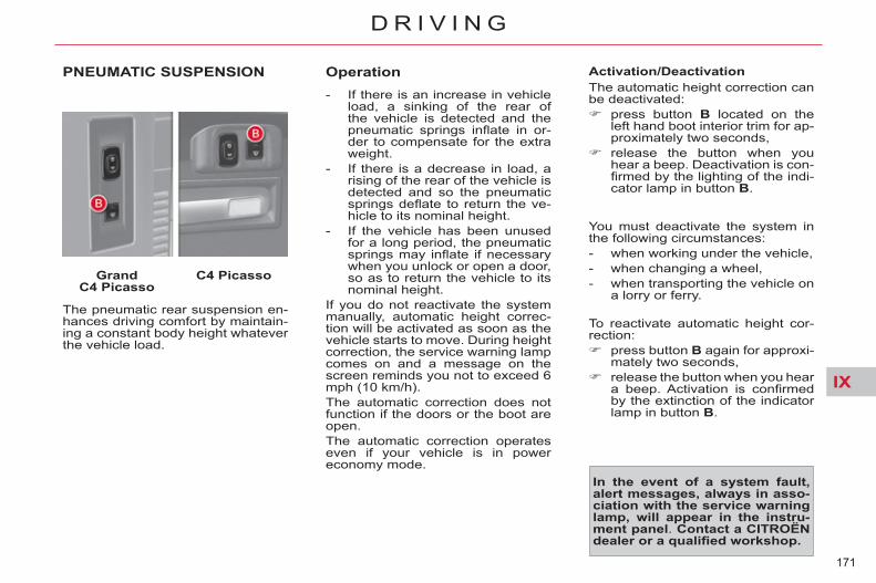
IX
171
D R I V I N G
PNEUMATIC SUSPENSION
Grand C4 Picasso
C4 Picasso
The pneumatic rear suspension en-hances driving comfort by maintain-ing a constant body height whatever the vehicle load.
Operation - If there is an increase in vehicle
load, a sinking of the rear of the vehicle is detected and the pneumatic springs infl ate in or-der to compensate for the extra weight.
- If there is a decrease in load, a rising of the rear of the vehicle is detected and so the pneumatic springs defl ate to return the ve-hicle to its nominal height.
- If the vehicle has been unused for a long period, the pneumatic springs may infl ate if necessary when you unlock or open a door, so as to return the vehicle to its nominal height.
If you do not reactivate the system manually, automatic height correc-tion will be activated as soon as the vehicle starts to move. During height correction, the service warning lamp comes on and a message on the screen reminds you not to exceed 6 mph (10 km/h). The automatic correction does not function if the doors or the boot are open. The automatic correction operates even if your vehicle is in power economy mode.
Activation/Deactivation The automatic height correction can be deactivated: press button B located on the
left hand boot interior trim for ap-proximately two seconds,
release the button when you hear a beep. Deactivation is con-fi rmed by the lighting of the indi-cator lamp in button B .
In the event of a system fault, alert messages, always in asso-ciation with the service warning lamp, will appear in the instru-ment panel . Contact a CITROËN dealer or a qualifi ed workshop.
You must deactivate the system in the following circumstances: - when working under the vehicle, - when changing a wheel, - when transporting the vehicle on
a lorry or ferry.
To reactivate automatic height cor-rection: press button B again for approxi-
mately two seconds, release the button when you hear
a beep. Activation is confi rmed by the extinction of the indicator lamp in button B .

IX
172
D R I V I N G
Loading/unloading assistance
Grand C4 Picasso
C4 Picasso
The pneumatic suspension has an additional function: the possibility to raise or lower the height of the rear of the vehicle when stationary, in or-der to facilitate loading/unloading of the boot.
Increasing the height of the boot fl oor Press continuously the top con-
trol A , which is located in the boot, on the left-hand side.
This action will be accompanied by an audible signal. You can stop the movement at any time by releasing the control. 3 beeps will confi rm that the move-ment has gone as far as it can.
Returning to the normal height Press briefl y the bottom of con-
trol A twice.
Decreasing the height of the boot fl oor Press continuously the bottom of
control A . This action will be accompanied by an audible signal. You can stop the movement at any time by releasing the control. 3 beeps will confi rm that the move-ment has gone as far as it can.
Returning to the normal height Press briefl y the top of control A
twice.
Driving with the boot in a low position may damage underbody components.
Particular points - If you start the vehicle without
having returned it to the normal height, automatic correction will activate as soon as the vehicle starts to move. During the cor-rection, the service warning lamp comes on and a message on the screen reminds you not to exceed 6 mph (10 km/h).
- Loading assistance does not function in the following circum-stances: - If button B is illuminated, - in power economy mode,
- when you fi rst use the function, press control A for two seconds to initialise the system. The sys-tem will respond normally to sub-sequent operation of the control.

173
C H E C K S
PARTNERS IN PERFORMANCE AND PROTECTING THE ENVIRONMENT Innovation in the search for performance For over 40 year, the TOTAL Research and Development departments have developed for CITROËN, lubricants to match the latest technical innovations on CITROËN vehi-cles, both for competition and for everyday motoring. For you, this is an assurance that you will obtain of the best performance for your engine.
Optimum protection for your engine By having your CITROËN vehicle serviced with TOTAL lubricants, you are contributing towards im-proving the life and performanc-es of your engine, while also protecting the environment.
prefers
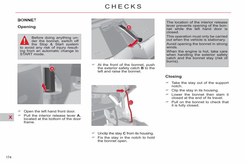
X
174
C H E C K S
Opening
At the front of the bonnet, push the exterior safety catch B to the left and raise the bonnet.
Unclip the stay C from its housing. Fix the stay in the notch to hold
the bonnet open.
Closing Take the stay out of the support
notch. Clip the stay in its housing. Lower the bonnet then slam it
closed at the end of its travel. Pull on the bonnet to check that
it is fully closed.
The location of the interior release lever prevents opening of the bon-net while the left hand door is closed. This operation must only be carried out when the vehicle is stationary. Avoid opening the bonnet in strong winds. When the engine is hot, take care when handling the exterior safety catch and the bonnet stay (risk of burns).
Open the left hand front door. Pull the interior release lever A ,
located at the bottom of the door frame.
Before doing anything un-der the bonnet, switch off the Stop & Start system
to avoid any risk of injury result-ing from an automatic change to START mode.

X
175
C H E C K S
BLEEDING THE DIESEL FUELFILTER Protective cover
Removal
Remove the protective cover by unclipping fi rst point 1 , then 3 and 4 .
Unclip point 2 pulling towards you, then lift.
Refi tting
Clip point 2 fi rst. Lower the cover, centring it. Clip points 1 and 4 , pushing ver-
tically and slightly rearwards. Clip point 3 , pushing vertically.
Bleeding water from the fuel filter
Bleed the fi lter regularly (at every oil change). To evacuate the water, slacken the bleed screw or the water-in-Diesel sensor, which is located at the base of the fi lter. Persist until water ceases to fl ow out. Then retighten the bleed screw or the water-in-Diesel sensor.

X
176
C H E C K S
RUNNING OUT OF FUEL(DIESEL)
1.6 litre HDi engine Detach the protective cover for ac-cess to the priming pump.
2.0 litre HDi engine Detach the protective cover for ac-cess to the priming pump.
Priming the fuel system In the event of running out of fuel: after fi lling (minimum 5 litres),
squeeze the manual priming pump repeatedly, until some re-sistance is felt,
then operate the starter, gently pressing the accelerator until the engine starts.
If the engine fails to start at the fi rst attempt, wait 15 seconds before trying again. If the engine fails to start after a few attempts, repeat the procedure from the beginning. When the engine is idling, accelerate gently to complete the purge of the circuit.
HDi engines are of a highly technical nature. All maintenance and repairs
must be done only by a CITROËN dealer or a qualifi ed workshop.
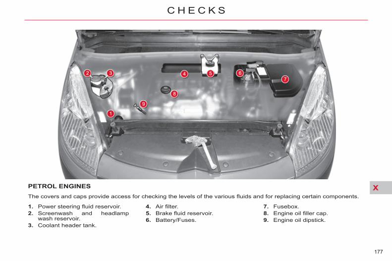
X
177
C H E C K S
PETROL ENGINES The covers and caps provide access for checking the levels of the various fl uids and for replacing certain components.
1. Power steering fl uid reservoir. 2. Screenwash and headlamp
wash reservoir. 3. Coolant header tank.
4. Air fi lter. 5. Brake fl uid reservoir. 6. Battery/Fuses.
7. Fusebox. 8. Engine oil fi ller cap. 9. Engine oil dipstick.

X
178
C H E C K S
* According to engine.
DIESEL ENGINES The covers and caps provide access for checking the levels of the various fl uids, for replacing certain components and for priming the fuel system.
1. Power steering fl uid reservoir. 2. Screenwash and headlamp
wash reservoir. 3. Coolant header tank 4. Brake fl uid reservoir. 5. Battery/Fuses.
6. Fusebox. 7. Air fi lter. 8. Engine oil fi ller cap. 9. Engine oil dipstick. 10. Priming pump * . 11. Bleed screw * .
As the Diesel fuel system is pressurised, any work on this system is prohibited.

X
179
C H E C K S
CHECKING LEVELS
Oil level
Oil specifi cation The oil must be the correct grade for your engine and conform to the manufacturer's recommendations.
Brake fl uid level
Changing the fl uid Refer to the servicing booklet for de-tails of the interval for this operation.
Fluid specifi cation The brake fl uid must conform to the manufacturer's recommendations and meet the DOT4 standard.
The check is carried out ei-ther when the ignition is switched on using the oil lev-el indicator on the instrument panel, or using the dipstick.
This manual check will only be cor-rect if the vehicle is on level ground and the engine has been off for more than 30 minutes. It is normal to top up the oil lev-el between two services (or oil changes). CITROËN recommends that you check the level, and top up if necessary, every 3 000 miles (5 000 kms).
The brake fl uid level should be close to the "MAX" mark. If it is not, check the brake pad wear.
In order to maintain the re-liability of the engine and emission control system,
the use of additives in the engine oil is prohibited.
Take care when working under the bonnet, as cer-tain areas of the engine may be extremely hot (risk of burns).
Power steering fl uid level
The power steering fl uid level should be close to the "MAX" mark. With the en-gine cold, unscrew the cap to check the level.
If a level drops signifi cantly, have the corresponding system checked by a CITROËN dealer or a qualifi ed workshop. Check all of these levels regularly and top them up if necessary, unless otherwise indicated.
Engine oil change Refer to the servicing booklet for de-tails of the interval for this operation.
After topping up the oil, the check when switching on the ignition with the oil level indicator in the instru-ment panel is not valid during the 30 minutes after topping up.
X
180
C H E C K S
Screenwash and headlamp wash fl uid
Fluid specifi cation For optimum cleaning and to avoid freezing, this fl uid must not be topped up with or replaced with plain water.
Diesel additive level (Diesel engine with particle emission filter) A low additive level is indicated by illumination of the service warning lamp, accompanied by an audible warning and a message in the multi-function screen.
Topping up This additive must be topped up by a CITROËN dealer or a qualifi ed workshop without delay.
Used products
Avoid prolonged contact of used oil or fl uids with the skin.
Most of these fl uids are harmful to health or indeed very corrosive.
Do not discard used oil or fl uids into sewers or onto the ground. Take used oil to a CITROËN
dealer or a qualifi ed workshop (France) or to an authorised waste disposal site.
In the case of vehicles fi tted with headlamp washers, the low fl uid level is indicated by an audible signal and a
message in the screen. Top up the reservoir when you next stop the vehicle.
Coolant level
Changing the coolant The coolant does not have to be changed.
Fluid specifi cation The coolant must conform to the manufacturer's recommendations.
The coolant level should be close to the "MAX" mark but should never exceed it. When the engine is warm,
the temperature of the coolant is regulated by the fan. This can oper-ate with the ignition off. On vehicles which are fi tted with a particle emission fi lter, the fan may operate after the vehicle has been switched off, even if the en-gine is cold. In addition, as the cooling system is pressurised, wait at least one hour after switching off the engine before carrying out any work. To avoid any risk of scalding, un-screw the cap by two turns to al-low the pressure to drop. When the pressure has dropped, remove the cap and top up the level.

X
181
C H E C K S
CHECKS
12 V battery The battery does not re-quire any maintenance. However, check that the terminals are clean and correctly tightened, partic-
ularly in summer and winter. When carrying out work on the bat-tery, refer to the "Practical information" section for details of the precautions to be taken before disconnecting the battery and following its reconnection.
Particle filter system (Diesel) Complementary to the catalytic converter, this fi lter makes an ac-tive contribution to the preservation of air quality by the retaining of the unburnt pollutant particles. Black exhaust fumes are thus no longer emitted. After prolonged idling or driving at very low speeds, you may oc-casionally notice water vapour be-ing emitted from the exhaust when accelerating. This is of no conse-quence to the running of the vehicle or to the environment.
If there is risk of clogging, a mes-sage appears on the multifunction screen, accompanied by an audible signal and lighting of the service warning lamp. This alert tells you that the particle fi lter is starting to fi ll up (in condi-tions of urban driving of excep-tionally long duration: low speeds, traffi c jams etc.) To regenerate the fi lter, it is advised to drive as soon as possible, when traffi c conditions permit, at a speed of 40 mph (around 60 km/h) or more for at least fi ve minutes (until the alert message disappears). If this alert persists, consult a CITROËN dealer or a qualifi ed workshop.
The presence of this label, in par-ticular with the Stop & Start system, indicates the use of a specifi c 12 V lead-acid battery with special tech-nology and specifi cation, for which the involvement of a CITROËN dealer or a qualifi ed workshop is required when replacing or discon-necting the battery.
Failure to observe this recommen-dation may shorten the life of the battery. Unless otherwise indicated, check
these components in accordance with the servicing booklet and ac-cording to your engine. Otherwise, have them checked by a CITROËN dealer or a qualifi ed workshop.
Air filter and passenger compartment filter
Refer to the servicing booklet for details of the replacement intervals for these components. Depending on the environ-
ment (e.g. dusty atmosphere) and the use of the vehicle (e.g. city driv-ing), replace them twice as often if necessary (refer to the "Engines" section). A clogged passenger compartment fi lter may have an adverse effect on the performance of the air condition-ing system and generate undesir-able odours.
Oil filter Replace the oil fi lter each time the engine oil is changed. Refer to the servicing booklet for details of the
replacement interval for this compo-nent.

X
182
C H E C K S
Brake pads Brake wear depends on the style of driving, par-ticularly in the case of ve-hicles used in town, over short distances. It may be
necessary to have the condition of the brakes checked, even between vehicle services. Unless there is a leak in the circuit, a drop in the brake fl uid level indicates that the brake pads are worn.
Manual gearbox The gearbox does not re-quire any maintenance (no oil change).
6-speed electronic gearbox system
The gearbox does not re-quire any maintenance (no oil change).
Automatic gearbox
The gearbox does not re-quire any maintenance (no oil change).
Brake disc wear
For information on checking brake disc wear, contact a CITROËN dealer or a quali-fi ed workshop.
Electric parking brake
This system does not require any routine servicing. However, in the event of a problem, have the system checked by a CITROËN dealer or a qualifi ed workshop. For more information, see "Driving - Electric parking brake - § Operating faults".
Refer to the servicing booklet for the details of the level checking interval for this component.
Refer to the servicing booklet for de-tails of the checking interval for this component.
Refer to the servicing booklet for de-tails of the level checking interval for this component.

XI
183
P R A C T I C A L I N F O R M A T I O N
TEMPORARY PUNCTUREREPAIR KIT
Using the kit
The kit is located in the boot under the fl oor or under the fl ap in the sec-ond row left-hand passenger foot-well (open by turning the screw a quarter of a turn).
Tick the wheel to be repaired on the speed limitation sticker enclosed then affi x the sticker to the vehicle's steering wheel to remind you that a wheel is in temporary use.
Switch off the ignition. Clip the cartridge 1 on the com-
pressor 2 .
Check that the switch A is tilted to position "0" .
Connect the pipe of the car-tridge 1 to the valve of the tyre to be repaired.
Unwind the pipe of the compres-sor 2 fully before connecting it to the cartridge.
Connect the compressor's elec-tric plug to the vehicle's 12 V socket.
Start the vehicle and leave the engine running.
Complete system consisting of a compressor and a sealant cartridge which permits temporary repair of a tyre so that you can drive to the nearest garage.
It is designed to repair holes of a maximum diameter of 4 mm, locat-ed exclusively on the tyre tread or shoulder. Avoid removing any for-eign bodies which have penetrated the tyre.

XI
184
P R A C T I C A L I N F O R M A T I O N
Remove the compressor and store the cartridge in the plastic bag, supplied in the kit, to avoid staining your vehicle with traces of fl uid.
Drive immediately for approxi-mately two miles (three kilome-tres), at reduced speed (between 15 and 35 mph - 20 and 60 km/h), to plug the puncture.
Stop to check the repair and the pressure.
Connect the compressor pipe di-rectly to the valve of the repaired wheel.
Switch on the compressor by moving the switch A to position "1" until the tyre pressure reaches 2.0 bars.
If this pressure has not been reached after approximately three minutes, the tyre cannot be re-paired; contact a CITROËN dealer or a qualifi ed workshop for assis-tance.

XI
185
P R A C T I C A L I N F O R M A T I O N
Connect the compressor's elec-tric plug to the vehicle's 12 V socket again.
Start the vehicle again and leave the engine running.
Adjust the pressure using the compressor (to infl ate: switch A in position "1" ; to defl ate: switch A in position "0" and press button B ), in accordance with the vehicle's tyre pressure label (located on the door aper-ture on the driver's side), then re-member to check that the leak is plugged correctly (no further loss of pressure after several miles).
Remove the compressor, then store the whole kit.
Drive at reduced speed (50 mph [80 km/h]).
Visit a CITROËN dealer or a qualifi ed workshop as soon as possible to have the tyre repaired or replaced by a technician.
Take care, the sealant cartridge contains ethyl-ene-glycol. This product is
harmful if swallowed and causes irritation to the eyes. Keep it out of reach of children. The expiry date of the sealant is indicated on the base of the car-tridge. The cartridge is designed for a sin-gle use; even if only partly used, it must be replaced. After use, do not discard the car-tridge into the environment, take it to a CITROËN dealer or to an au-thorised waste disposal site. Do not forget to obtain a new sealant cartridge, available from a CITROËN dealer or a qualifi ed workshop.
Under-inflation detection If the vehicle is fi tted with tyre un-der-infl ation detection, the tyre under-infl ation warning lamp will remain on after the wheel has been repaired until the system is reini-tialised by a CITROËN dealer or a qualifi ed workshop.

XI
186
P R A C T I C A L I N F O R M A T I O N
CHANGING A WHEEL
Access to the tools
Depending on equipment, the tools are to be found either in the com-partment under the second-row pas-senger footwells (the compartment is opened by turning the screw a quarter turn) or in the well under the third-row left-hand seat.
1. Tool for removing the central trim on alloy wheels *
or 2. Tool for removing the chrome
covers on the wheel bolts on al-loy wheels *
3. Centring guide * 4. Wheelbrace 5. Vehicle jack with integral handle 6. Security bolt socket (located in
the glovebox) **
Switch on your hazard warning lamps, ensure that any passengers leave the
vehicle and fi nd a safe place to wait away from traffi c (e.g. behind crash barriers or on a grass verge). Never get underneath the vehicle if it is supported only by the jack; use a stand. The jack and the tools are specifi c to your vehicle. Do not use for any other purpose. Do not to exceed a speed of 50 mph (80 km/h) on your spare wheel. Have the original wheel repaired and refi tted as soon as possible.
7. Short extension for C4 Picasso 8. Long extension for Grand C4
Picasso (located in the well under the right hand third row seat)
9. Two chocks, provided for chang-ing a wheel or for other uses on the vehicle (such as releasing the electric parking brake)
10. Parking brake release tool (elec-tric parking brake)
11. Removable towing eye
* With alloy wheels only. ** With security bolts only.

XI
187
P R A C T I C A L I N F O R M A T I O N
Grand C4 Picasso C4 Picasso
Access to the spare wheel
Taking out the wheel (Grand C4 Picasso) Lift the boot fl oor covering to re-
veal the spare wheel carrier drive on the right.
Take the extension 8 clipped in the rear of the well below the right hand third-row seat.
Lift up the spare wheel carrier drive aperture cap.
Fit the extension to the drive then engage the head of the wheel-brace 4 on the extension.
Turn the assembly clockwise to the end of its travel to lower the spare wheel carrier; the spare wheel is now resting on the ground.
Pull the wheel towards you and pass the linking plate through the centre of the wheel.
With the damaged wheel now under the vehicle fl oor, the vehicle has reduced
ground clearance, so take extra care when reversing or driving on uneven surfaces, including kerbs. Retrieval of the spare wheel and stowage of the affected road wheel are operations that should be done with the vehicle standing on its wheels, not supported by the jack.
Putting the wheel back in place The tyre valve must be facing
upwards. Pass the linking plate through
the centre of the wheel (fi rst re-moving the central trim on cer-tain alloy wheels).
Turn the carrier drive anti-clock-wise to draw in the carrier cable. Initially the drive will turn freely, then the cable will tighten to raise the wheel.
Check that the wheel is tight against the vehicle fl oor and not interfering with other nearby components (e.g. the exhaust).
Stow the tools. Taking out the wheel (C4 Picasso) Lift the boot fl oor covering to re-
veal the spare wheel carrier drive on the left.
Take the extension 7 from the set of tools.
Lift up the spare wheel carrier drive aperture cap, if fi tted.
Fit the extension to the drive then engage the head of the wheel-brace 4 on the extension.
Turn the assembly clockwise to the end of its travel to lower the spare wheel carrier; the spare wheel is now resting on the ground.
Pull the wheel towards you and pass the linking plate through the centre of the wheel.

XI
188
P R A C T I C A L I N F O R M A T I O N
Removing a wheel
Park the vehicle on level, stable and non-slippery ground. Apply the parking brake (a message and a warning lamp appear on the instrument panel).
Switch off the ignition and en-gage fi rst gear or reverse gear depending on the slope (posi-tion P if an automatic gearbox, D or R if a 6-speed electronic gearbox).
Use a chock to secure the vehi-cle more safely. Place the chock 9 in front of the wheel that is op-posite the wheel affected.
Detach the trim using the remov-ing tool 4 , pulling in the area of the valve.
For vehicles with alloy wheels, insert the trim removing tool 1 into the recess in the central trim and lever it off.
For vehicles with alloy wheels that have visible bolts, remove the chrome covers using the re-moving tool 2 .
Slacken the wheel bolts. For ve-hicles with alloy wheels, undo the security bolts using the secu-rity socket 6 .
Position the jack under the vehi-cle, at the jacking point A closest to the wheel to be changed.
Unwind the jack 5 until its brack-et is in contact with the ground. Make sure that the jack is verti-cal under the jacking point used.
Continue to extend the jack so as to raise the vehicle.
Undo the wheel bolts and re-move the wheel.
Before any operation of this sort, it is advisable to deactivate your pneumatic suspension.

XI
189
P R A C T I C A L I N F O R M A T I O N
Temporary use spare wheel
If your vehicle is equipped with a spare wheel for temporary use only, when fi tting this it is normal to ob-serve that the wheel bolts do not come to bear directly on the wheel rim. The spare wheel is secured by the conical tapering of the wheel bolt’s shaft. When refi tting the original wheel, en-sure that the wheel bolts and wash-ers are clean and in good condition.
Fitting a wheel Position the wheel with the aid of
the centring guide 3 . Do up the 3 bolts by hand, then
remove the centring guide 3 . Position the 4 th bolt.
Pre-tighten the wheel bolts, us-ing the wheelbrace 4 .
Retract the jack 5 and disengage it. Tighten the wheel bolts, using
the wheelbrace 4 . Ensure that the tyre pressure is
correct.
Under-infl ation detection Wheels with under-infl ation detection have tyre pressure sensors. Have repairs to them carried out by a CITROËN dealer or a qualifi ed workshop. The spare wheel does not have a sensor.
Security bolts (alloy wheels) Each wheel may be equipped with one security bolt (depending on the country of sale). To remove it: remove its protective cover us-
ing of the tool for removing the chrome covers 2 .
use the security bolt socket 6 with the wheelbrace 4 .
Spare wheel dimensions If your spare wheel has dimensions different from those of the standard vehicle wheels (identifi ed by a la-bel), it is imperative to use the spare wheel only temporarily, to drive with caution, not to exceed 50 mph (80 km/h) and to have the tyre re-paired and the standard wheel refi t-ted as soon as possible.
Tyre pressures These are indicated on the label on the front left-hand door pillar (see "Technical Data - Identifi cation markings").
The wheel bolts are specifi c to each type of wheel.
If new wheels are fi tted, check with your CITROËN dealer or a qualifi ed workshop that the wheel bolts are compatible with the new wheels. Make a note of the code number on the head of the security bolt sock-et. This will enable you to obtain a replacement security bolt socket from your dealer.
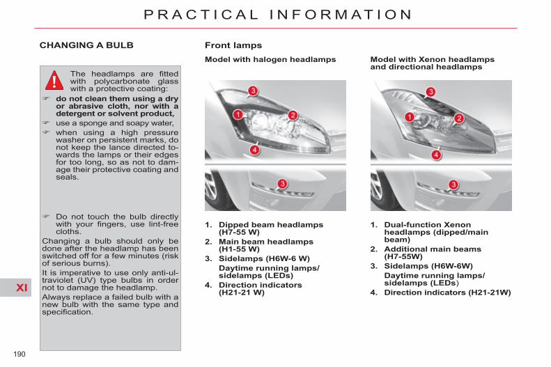
XI
190
P R A C T I C A L I N F O R M A T I O N
CHANGING A BULB
The headlamps are fi tted with polycarbonate glass with a protective coating:
do not clean them using a dry or abrasive cloth, nor with a detergent or solvent product,
use a sponge and soapy water, when using a high pressure
washer on persistent marks, do not keep the lance directed to-wards the lamps or their edges for too long, so as not to dam-age their protective coating and seals.
Do not touch the bulb directly with your fi ngers, use lint-free cloths.
Changing a bulb should only be done after the headlamp has been switched off for a few minutes (risk of serious burns). It is imperative to use only anti-ul-traviolet (UV) type bulbs in order not to damage the headlamp. Always replace a failed bulb with a new bulb with the same type and specifi cation.
Front lamps
1. Dipped beam headlamps (H7-55 W)
2. Main beam headlamps (H1-55 W)
3. Sidelamps (H6W-6 W ) Daytime running lamps/
sidelamps (LEDs) 4. Direction indicators
(H21-21 W)
Model with halogen headlamps Model with Xenon headlamps and directional headlamps
1. Dual-function Xenon headlamps (dipped/main beam)
2. Additional main beams (H7-55W)
3. Sidelamps (H6W-6W) Daytime running lamps/
sidelamps (LEDs ) 4. Direction indicators (H21-21W)

XI
191
P R A C T I C A L I N F O R M A T I O N
Main beam headlamps
Remove the rubber cover. Detach the clips by lowering
them on each side of the bulb. Pull on the bulb-holder to remove it. Replace the faulty bulb. Push the bulb-holder back into
its housing. Reattach the clips. Refi t the rubber cover.
Dual-function Xenon headlamps (dipped/main beam)
Additional main beam headlamps Remove the rubber cover. Rotate the bulb-holder a quarter
turn anti-clockwise and remove it from its housing.
Replace the faulty bulb. Reposition the bulb-holder by
pushing it in, tightening it by a quarter turn clockwise.
Refi t the rubber cover.
If the headlamp bears this symbol, any operation to change the Xenon dual-function directional head-
lamp (D1S-35 W) must be carried out by professionals (risk of elec-trocution). Contact a CITROËN dealer or a qualifi ed workshop. It is recommended to change both bulbs at the same time if one of them is faulty.
Dipped beam headlamps
Remove the rubber cover. Rotate the bulb-holder a quarter
turn anti-clockwise and remove it from its housing.
Replace the faulty bulb. Reposition the bulb-holder by
pushing it in, tightening it by a quarter turn clockwise.
Refi t the rubber cover.

XI
192
P R A C T I C A L I N F O R M A T I O N
Sidelamps
Rotate the bulb-holder a quarter turn anti-clockwise.
Remove it from its housing. Replace the faulty bulb. Reposition the bulb-holder. Rotate it a quarter turn clockwise
to reposition in its housing.
Direction indicators
The direction indicator bulb is locat-ed underneath the main beam bulb. Remove the rubber cover. Pull on the bulb-holder to remove it. Replace the faulty bulb. Reposition the bulb-holder in the
bracket and push it in. Refi t the rubber cover.
Integrated direction indicator side repeaters
To change the repeater, press down-wards fi rmly on the zone indicated by the arrow, then pull the repeater. Repeaters can be obtained from a CITROËN dealer or a qualifi ed workshop.

XI
193
P R A C T I C A L I N F O R M A T I O N
Front foglamps (H11-55 W)
Insert the key in the notch A , tilting the bulb-holder cover, located un-derneath the bumper, then insert the key in the notch B to remove it.
Undo the lamp. Tilt the bulb-holder. Change the faulty bulb. Reposition the bulb-holder. Do up the lamp and refi t the bulb-
holder cover fi rmly in place.
Rear foglamp (P21 W)
Pass your hand underneath the bumper to reach the bulb-holder.
Rotate the bulb-holder a quarter turn.
Pull on the bulb-holder. Rotate the bulb a quarter turn to
remove it. Replace the faulty bulb. Fit the bulb. Reposition the bulb-holder by
rotating it a quarter turn.
For the replacement of this type of LED lamp, contact a CITROËN dealer or a qualifi ed workshop.
Changing daytime running lamps/sidelamps (LEDs)

XI
194
P R A C T I C A L I N F O R M A T I O N
Rear lamps (C4 Picasso)
1. Direction indicators (PY21W)
2. Brake lamps/sidelamps (P21/5W)
3. Reversing lamp (P21W )
Identify the faulty bulb. With the boot open, press on the
plastic cover A , located close to the lamp unit, to release it from its housing.
Undo the two screws B on the side of the lamp unit and detach the lamp unit by pulling it rear-wards.
Disconnect the connector linking the lamp unit with the tailgate.
Remove the bulb-holder. Replace the bulbs. To remove a bulb, rotate it a
quarter turn. To refi t the bulb, rotate it a quar-
ter turn in the other direction. Reposition the bulb-holder. Reconnect the connector to the
lamp unit.
Lamps mounted on the bodywork
Identify the faulty bulb. With the boot open, remove the
plastic cover on the tailgate. Remove the bulb-holder from its
housing. Replace the bulb. To remove a bulb, rotate it a
quarter turn. To refi t the bulb, rotate it a quar-
ter turn in the other direction. Reposition the bulb-holder. Refi t the plastic cover.
Lamps mounted on the tailgate
Refi t the lamp unit on the body and do up the two screws.
Reposition the plastic cover by pressing on it.
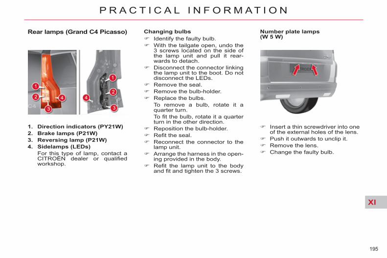
XI
195
P R A C T I C A L I N F O R M A T I O N
Rear lamps (Grand C4 Picasso)
1. Direction indicators (PY21W) 2. Brake lamps (P21W) 3. Reversing lamp (P21W) 4. Sidelamps (LEDs) For this type of lamp, contact a
CITROËN dealer or qualifi ed workshop.
Changing bulbs Identify the faulty bulb. With the tailgate open, undo the
3 screws located on the side of the lamp unit and pull it rear-wards to detach.
Disconnect the connector linking the lamp unit to the boot. Do not disconnect the LEDs.
Remove the seal. Remove the bulb-holder. Replace the bulbs. To remove a bulb, rotate it a
quarter turn. To fi t the bulb, rotate it a quarter
turn in the other direction. Reposition the bulb-holder. Refi t the seal. Reconnect the connector to the
lamp unit. Arrange the harness in the open-
ing provided in the body. Refi t the lamp unit to the body
and fi t and tighten the 3 screws.
Number plate lamps (W 5 W)
Insert a thin screwdriver into one of the external holes of the lens.
Push it outwards to unclip it. Remove the lens. Change the faulty bulb.

XI
196
P R A C T I C A L I N F O R M A T I O N
Third brake lamp with bulb(W5W) With the boot open, detach the
interior trim. Undo the nuts. Using a thin screwdriver, detach
the 3 retaining lugs. Remove the lamp via the exterior
of the tailgate. Remove the bulb-holder. Change the faulty bulb(s). To refi t, carry out these operations in reverse order.
Third brake lamp (LEDs)
For the replacement of this type of LED lamp, contact a CITROËN dealer or a qualifi ed workshop.
Interior lighting
Interior lamp (1/W5W)
Detach the cover of the interior lamp 1 with a thin screwdriver, close to the button, to access the faulty bulb.
Map reading lamps (2/W5W)
Detach the cover of the interior lamp. To access the faulty bulb, detach the partition for the reading lamp 2 concerned, as necessary.
Boot lamps (W5W)
Detach the unit by pushing it rear-wards.
Torch (Krypton 3.6 V)
Open the tab. Push with a fl at screwdriver in
the hole under the tab and re-cover the bulb unit.
Open the bulb unit fully to change the bulb.

XI
197
P R A C T I C A L I N F O R M A T I O N
CHANGING A FUSE
Before replacing a fuse: - the cause of the failure must be
identifi ed and corrected, - all electrical consumers must be
switched off, - your vehicle must be stationary,
ignition off. Identify the failed fuse by reference to the tables and diagrams below.
Access to tools The extraction tweezer A is fi tted on the back of the dashboard fusebox cover. For access to it: unclip the cover by pulling at the
top right, then left, pull the cover down, remove the tweezer.
Changing a fuse Use the special tweezer A to ex-
tract the fuse from its housing and check the condition of its el-ement.
Replace the failed fuse with a fuse of the same rating (same colour)
Use of a fuse of different rating may cause a malfunction (risk of fi re).
If the failure occurs again soon after replacing the fuse, have the electri-cal system checked by a CITROËN dealer or a qualifi ed workshop.
Good Failed
Tweezer A
Fuses under the dashboard
Your vehicle's electrical system is designed to oper-ate with either standard or optional equipment.
Before installing electrical equip-ment or accessories on your vehi-cle, consult a CITROËN dealer or a qualifi ed workshop. CITROËN declines all responsibil-ity for the consequences and costs that are caused by faults or repairs on your vehicle resulting from the installation of accessories that are not supplied and/or not rec-ommended by CITROËN and not installed according to its instruc-tions, particularly when the energy consumption of all of the additional accessories connected exceeds 10 milliamperes (Ma).

XI
198
P R A C T I C A L I N F O R M A T I O N
Fuses under the dashboard
Access to the fuses Undo the screw by a quarter turn
and pivot the housing.
Table of fuses
Fuse N° Rating Functions
F1 15 A Rear screen wipe
F2 30 A Locking and unlocking earth
F3 5 A Airbags and pretensioners
F4 10 A Multimedia, photochromatic rear view mirror, particle fi lter, diagnostic socket, air conditioning, manual headlamp height adjustment
F5 30 A Front windows, front door electronic control panel, panoramic sunroof
F6 30 A Rear windows
F7 5 A Interior lamps, cooled glovebox, radio
F8 20 A Multifunction screen, radio, steering mounted controls, multimedia, under infl ation detection, alarm, trailer
F9 30 A Multimedia, front 12 V sockets, torch, radio
F10 15 A Height corrector (suspension)
F11 15 A Brake switch, ignition switch
F12 15 A Parking sensors, automatic wipers and lighting, passenger’s electric seat, lane departure warning system, Hi-Fi amplifi er, trailer
F13 5 A Engine relay unit (BSM), driver’s electric seat
F14 15 A Air conditioning, Bluetooth ® hands-free system, automatic gearbox selector lever, airbags, instrument panel
F15 30 A Locking and unlocking
F16 - SHUNT
F17 40 A Heated rear screen

XI
199
P R A C T I C A L I N F O R M A T I O N
Access to the second dashboard fusebox
After any operation on the fuses in the fusebox, check that the fusebox cover is refi tted correctly for their protection.
Table of fuses
Fuse N° Rating Functions
F29 20 A Heated seats
F30 - Not used
F31 40 A Trailer relay unit
F32 15 A Rear 12 V socket
F33 5 A Parking sensors, automatic wipers and lighting, passenger’s electric seat, lane departure warning system, Hi-Fi amplifi er
F34 5 A Trailer
F35 - Not used
F36 20 A Hi-Fi amplifi er
F37 10 A Air conditioning, lighting pack
F38 30 A Driver’s electric seat
F39 5 A Fuel fi ller fl ap
F40 30 A Passenger’s electric seat, panoramic sunroof

XI
200
P R A C T I C A L I N F O R M A T I O N
Fuses in the engine compartment
Access to the fuses Detach and remove the cover.
After any operation, carefully refi t the cover. If the cover is not cor-rectly positioned or not properly closed, this could cause serious problems on your vehicle. For the same reason, take care not to spill any liquid in the fusebox.
All work on the maxi-fuses, which are located in these fuseboxes and which give
extra protection, must be carried out by a CITROËN dealer or a qualifi ed workshop.

XI
201
P R A C T I C A L I N F O R M A T I O N
Fuse N° Rating Functions
F1 20 A Engine management
F2 15 A Horn
F3 10 A Screenwash pump
F4 20 A Headlamp wash pump
F5 15 A Engine components
F6 10 A Xenon dual-function directional headlamps, automatic headlamp height adjustment,clutch switch, protection switch box (BCP)
F7 10 A Automatic gearbox, engine coolant level switch, power steering
F8 25 A Starter motor
F9 10 A Stop lamp switch
F10 30 A Engine components
F11 40 A Rear blower
F12 30 A Screen wipe
F13 40 A Built-in Systems Interface (BSI)
F14 30 A Air pump, heat exchange saver
F15 10 A Right-hand main beam
F16 10 A Left-hand main beam
F17 15 A Left-hand dipped beam
F18 15 A Right-hand dipped beam
F19 15 A Engine components
F20 10 A Engine components
F21 5 A Cooling fan relay
Table of fuses

XI
202
P R A C T I C A L I N F O R M A T I O N
Fuses on the battery
After any operation, carefully refi t the cover. If the cover is not cor-rectly positioned or not properly closed, this could cause serious problems on your vehicle. For the same reason, take care not to spill any liquid in the fusebox.
Table of fuses
Access to the fuses Detach and remove the cover. Fuses F1 to F6 are located on
the small board, clipped verti-cally on the battery fusebox.
Fuses F7 to F12 are midi-fuses. All work on these fuses must be carried out by a CITROËN dealer or a qualifi ed workshop.
Fuse N° Rating Functions
F1 5 A Automatic gearbox actuator
F2 5 A Stop switch
F3 5 A Battery charge estimation ECU
F4 20 A ESP supply
F5 5 A ESP supply
F6 20 A ECU for 6-speed electronic gearbox/automatic gearbox

XI
203
P R A C T I C A L I N F O R M A T I O N
12 V BATTERY Procedure for starting the engine using another battery or for charging your fl at battery.
The Stop & Start battery does not have to be disconnected for charging.
The presence of this label, in particular with the Stop & Start system, indicates the use of a 12 V lead-acid battery with
special technology and specifi cation; the involvement of a CITROËN deal-er or a qualifi ed workshop is essential when replacing or disconnecting the battery.
After refi tting the battery, the Stop & Start system will only be active after a continuous period of immobilisa-tion of the vehicle, a period which depends on the climatic conditions and the state of charge of the bat-tery (up to about 8 hours).
* or position P for an automatic gearbox.
Access to the battery Before doing any work Immobilise the vehicle: ap-ply the parking brake, put
the gearbox in neutral * , then switch off the ignition. Check that all electrical equipment is switched off.
Check that the battery posts and terminals are clean. If they are cov-ered with sulphate (white or green deposit), disconnect them and clean them.
Batteries contain harmful substances such as sul-phuric acid and lead. They
must be disposed of in accordance with regulations and must not, in any circumstances, be discarded with household waste. Take used cell batteries and vehi-cle batteries to an authorised col-lection point.
The battery is located under the bonnet. For access to the (+) terminal: Release the bonnet using the
interior lever, then the exterior safety catch,
raise the bonnet and secure it with its stay,
lift the plastic cover for access to the (+) terminal.

XI
204
P R A C T I C A L I N F O R M A T I O N
Disconnecting the (+) terminal
Raise the lever D fully to release the clamp E .
Do not force the lever as locking will not be possible if the clamp is not positioned correctly; start the procedure again.
Reconnecting the (+) terminal Position the open clamp E of the
cable on the positive post (+) of the battery.
Press down on the clamp to po-sition it correctly on the battery post.
Lock the clamp by lowering the lever D .
Starting using another battery If the battery in your vehicle is fl at, the engine can be started using a slave battery (external or in another vehicle) and jump leads.
First ensure that the slave battery has a nominal volt-age of 12 V and a capac-
ity at least equal to that of the fl atbattery. Do not try to start the engine by connecting a battery charger. Do not disconnect the (+) terminal when the engine is running.
Connect the red lead to the (+) terminal of the fl at battery A , then to the (+) terminal of the slave battery B .
Connect one end of the green or black lead to the (-) terminal of the slave battery B (or the earth point on the slave vehicle).
Connect the other end to the earth point C on the broken-down vehicle.
Start the engine on the slave ve-hicle and leave the engine run-ning for a few minutes.
Operate the starter on the bro-ken-down vehicle and leave the engine running.
If the engine does not start straight away, switch off the ig-nition and wait a few moments before trying again.
With the engine idling, discon-nect the jump leads in reverse order.

XI
205
P R A C T I C A L I N F O R M A T I O N
Before disconnecting Go to the battery. Check that all of the openings -
doors, boot... - are closed but not locked.
Wait at least four minutes after switching off the ignition.
Charging Disconnect the (+) terminal. Follow the instructions on use
provided by the manufacturer of the charger.
Connect the red cable of the charger to the (+) post of the bat-tery, then the black cable to the (-) terminal.
Once charging is complete, dis-connect the charger cables in re-verse order.
The charging operation must be carried out in a well ventilated area and
well away from naked fl ames and sources of sparks, so as to avoid any risk of explosion and fi re. Do not try to charge a frozen bat-tery; the battery must fi rst be thawed out to avoid any risk of ex-plosion. If the battery has frozen, before charging, have it checked by a CITROËN dealer or a quali-fi ed workshop, who will ensure that the internal components have not been damaged and that the casing is not cracked, which would intro-duce the risk of a leak of toxic and corrosive acid.
Charging the battery using a battery charger If the battery of your vehicle is fl at or prior to taking the vehicle out of service for an extended period, you can charge the battery using a bat-tery charger. For information on the specifi cation of battery chargers compatible with your battery, refer to a CITROËN dealer or a qualifi ed workshop.
It is recommended that the battery be disconnected if the vehicle is not be used for more than a month.
Reinitialisation after reconnection
After any reconnection of the bat-tery, switch on the ignition and wait at least one minute before starting, to allow time for the initialisation of the electronic systems. By referring to the corresponding sections, you should set or initialise the following systems yourself: - the date and time, - the anti-pinch on the driver's
electric window and the sunroof. - the panoramic sunroof blind, - the multifunction screen set-
tings, - the audio system or navigation
system settings,
Check that there no error message or warning lamp comes on after switching on the ignition. However, if minor problems persist after carrying out these operations, contact a CITROËN dealer or a qualifi ed workshop.

XI
206
P R A C T I C A L I N F O R M A T I O N
ENERGY ECONOMY MODE System which manages the duration of use of certain functions to conserve a suffi cient level of charge in the battery. After the engine has stopped, you can still use functions such as the audio and telematics system, windscreen wipers, dipped beam headlamps, courtesy lamps, etc. for a maximum combined duration of thirty minutes.
Switching to economy mode Once this period has elapsed, a message appears on the multi-func-tion screen indicating that the vehi-cle has switched to economy mode and the active functions are put on standby. If a telephone call is being made at this time: - it will be maintained for 10 minu-
tes with your Audio system or MyWay hands-free system
- it will be maintained for 10 minu-tes with the NaviDrive, then it will transfer to your telephone de-pending on its model.
Exiting economy mode These functions are reactivated au-tomatically next time the vehicle is started. To resume the use of these functions immediately, start the engine and let it run for at least 5 minutes.
A fl at battery prevents the engine from starting (refer to the corresponding para-graph).
This period may be reduced con-siderably if the battery is not fully charged.

XI
207
P R A C T I C A L I N F O R M A T I O N
TOWING THE VEHICLE Procedure for having your vehicle towed or for towing another vehicle using a removable towing eye.
Access to the tools
According to equipment, the towing eye is installed in the storage fl ap under the second row passenger footwell or under the boot fl oor. To gain access to it: open one of the rear doors or the
boot (according to equipment), open the fl ap or raise the fl oor
(according to equipment), remove the towing eye from the
holder.
Towing your vehicle
On the front bumper, unclip the cover by pressing at the top left and pulling at the right.
Screw the towing eye in fully. Install the towing bar. Switch on the hazard warning
lamps on the towed vehicle. Place the gear lever in neutral
(position N on the electronic gearbox or automatic gearbox).
Towing another vehicle
On the rear bumper, unclip the cover by pressing at the bottom at pulling at the top.
Screw the towing eye in fully. Install the towing bar. Switch on the hazard warning
lamps on the towed vehicle.
Failure to observe this instruction could result in damage to certain braking components and the ab-sence of braking assistance the next time the engine is started.

XI
208
P R A C T I C A L I N F O R M A T I O N
General recommendations Observe the legislation in force in your country. Ensure that the weight of the towing vehicle is higher than that of the towed vehicle. The driver must stay at the wheel of the towed vehicle. Driving on motorways and fast roads is prohibited when towing. When towing a vehicle with all four wheels on the ground, always use an approved towing bar; rope and straps are pro-hibited. When towing a vehicle with the engine off, there is no longer any power assistance for braking or steering. In the following cases, you must always call on a professional recovery service: - vehicle broken down on a motorway or fast road, - when it is not possible to put the gearbox into neutral, unlock the steering, or release the parking brake, - towing with only two wheels on the ground, - where there is no approved towing bar available...
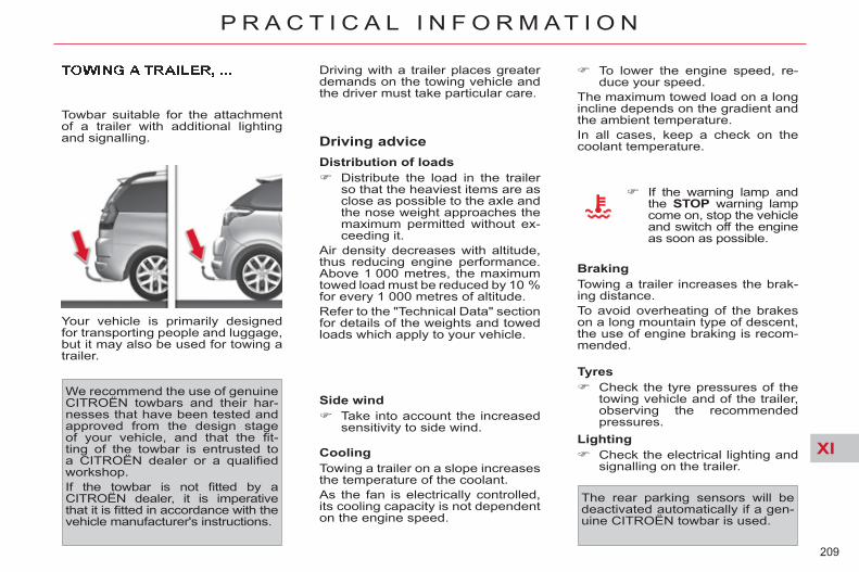
XI
209
P R A C T I C A L I N F O R M A T I O N
Towbar suitable for the attachment of a trailer with additional lighting and signalling.
Your vehicle is primarily designed for transporting people and luggage, but it may also be used for towing a trailer.
We recommend the use of genuine CITROËN towbars and their har-nesses that have been tested and approved from the design stage of your vehicle, and that the fi t-ting of the towbar is entrusted to a CITROËN dealer or a qualifi ed workshop. If the towbar is not fi tted by a CITROËN dealer, it is imperative that it is fi tted in accordance with the vehicle manufacturer's instructions.
Driving advice Distribution of loads Distribute the load in the trailer
so that the heaviest items are as close as possible to the axle and the nose weight approaches the maximum permitted without ex-ceeding it.
Air density decreases with altitude, thus reducing engine performance. Above 1 000 metres, the maximum towed load must be reduced by 10 % for every 1 000 metres of altitude. Refer to the "Technical Data" section for details of the weights and towed loads which apply to your vehicle.
Side wind Take into account the increased
sensitivity to side wind.
To lower the engine speed, re-duce your speed.
The maximum towed load on a long incline depends on the gradient and the ambient temperature. In all cases, keep a check on the coolant temperature.
If the warning lamp and the STOP warning lamp come on, stop the vehicle and switch off the engine as soon as possible.
Braking Towing a trailer increases the brak-ing distance. To avoid overheating of the brakes on a long mountain type of descent, the use of engine braking is recom-mended.
Tyres Check the tyre pressures of the
towing vehicle and of the trailer, observing the recommended pressures.
Lighting Check the electrical lighting and
signalling on the trailer.
The rear parking sensors will be deactivated automatically if a gen-uine CITROËN towbar is used.
Driving with a trailer places greater demands on the towing vehicle and the driver must take particular care.
Cooling Towing a trailer on a slope increases the temperature of the coolant. As the fan is electrically controlled, its cooling capacity is not dependent on the engine speed.

XI
210
P R A C T I C A L I N F O R M A T I O N
ROOF BARS
For your safety and to avoid damage to the roof and tailgate, the design of your vehicle requires the use of roof bars and roof boxes that are tested and approved by CITROËN. Regardless of the type of load car-rier to be mounted on the roof (roof box, bicycle carrier, ski carrier...), you must fi t transverse roof bars.
Recommendations Distribute the load evenly, avoid-
ing overloading on one side. Arrange the heaviest part of the
load as close as possible to the roof.
Anchor the load securely and fi t a warning fl ag part of it is over-hanging.
Drive gently, as the vehicle will be more liable to the effects of side winds (vehicle stability may be altered).
Remove the roof bars as soon as they are no longer needed.
Bicycle carrier Do not attach a strap-fi tting bicycle carrier to the following vehicle ver-sions: - C4 Picasso 5-seater (all versions); - C4 Picasso 7-seater version with
opening rear screen.
Maximum load, distributed over the roof bars (for a loading height not exceed-
ing 40 cm, except bicycle carrier): 80 kg. If the height exceeds 40 cm, adapt your speed to the profi le of the road to avoid damaging the roof bars and the fi xings on the roof. Please refer to national legislation in order to comply with the regula-tions concerning the transport of objects which are longer than the vehicle.
* According to country.
VERY COLD CLIMATE SCREEN * Removable protective screen which prevents the accumulation of snow at the radiator cooling fan.
Fitting Offer up the very cold climate
screen to the front of the lower section of the front bumper.
Press around its edge to engage its fi xing clips one by one.
Removal Use a screwdriver as a lever to
release each fi xing clip in turn.
Do not forget to remove the very cold climate screen: - when the ambient temperature
exceeds 10 °C, - when towing, - at speeds above 75 mph (120 km/h).

XI
211
P R A C T I C A L I N F O R M A T I O N
* To avoid any risk of jamming of the pedals: - ensure that the mat is posi-
tioned and secured correctly, - never fi t one mat on top of an-
other.
ACCESSORIES A wide range of accessories and genuine parts is available from the CITROËN dealer network. These accessories and parts have been tested and approved for reli-ability and safety. They are all adapted to your vehicle and benefi t from CITROËN's recom-mendation and warranty.
"Transport solutions": towbar har-ness, boot carpet, boot liner, boot spacers, transverse roof bars, bi-cycle carrier, ski carrier, roof boxes, towbars...
"Comfort": front and rear parking sensors, isotherm module, recharge-able torch, sun blinds, air defl ector, fragrance cartridges...
"Style": Alloy wheels, wheel embel-lishers...
"Protection": anti-theft alarm, wheel security devices, stolen ve-hicle tracking system, breathalyser, fi rst aid kit, warning triangle, high vis-ibility vest, dog guard, snow chains, anti-skid covers, foglamps kit, tem-porary puncture repair kit, booster cushions and child seats...
"Protection" : mats * , seat covers, mud fl aps, sill protectors, bumper protectors, vehicle covers...

XI
212
P R A C T I C A L I N F O R M A T I O N
The fi tting of electrical equipment or accessories which are not recommend-
ed by CITROËN may result in a failure of your vehicle's electronic system and excessive electrical consumption. Please note this precaution. You are advised to contact a CITROËN representative to be shown the range of recommended equipment and accessories.
Depending on the legislation in force in the country, it may be com-pulsory to have a high visibility safety vest, warning triangle and spare bulbs and fuses available in the vehicle.
"Multimedia": Bluetooth® hands-free system, audio systems, portable sat-ellite navigation system, DVD player, USB Box, speakers, 230 V/50 Hz socket, 230 V/12 V power supply adaptor, WiFi on board...
You can also obtain products for cleaning and maintenance (exterior and interior), topping up (screen-wash...) and replacement cartridges (for the temporary puncture repair kit...) from the CITROËN dealer network.
Installation of radio communication transmitters Before installing any after-market ra-dio communication transmitter, you can contact a CITROËN dealer for the specifi cation of transmitters which can be fi tted (frequency, maximum power, aerial position, specifi c instal-lation requirements), in line with the Vehicle Electromagnetic Compatibility Directive (2004/104/EC).

XII
213
T E C H N I C A L D A T A
MODELS: ENGINES AND GEARBOXES
Model codes: UA... UE... UD...
5FS-0 5FS-0/CU1
5FV-8/P 5FV-8/PCU1 RFJ-F
PETROL ENGINES VTi 120 THP 155 VTi 143
Cubic capacity (cc) 1 598 1 598 1 997
Bore x stroke (mm) 77 x 85.8 77 x 85.8 85 x 88
EU standard maximum power (kW) 88 115 103
Maximum power engine speed (rpm) 6 000 6 000 6 000
EU standard maximum torque (Nm) 160 240 200
Maximum torque engine speed (rpm) 4 250 1 400 4 000
Fuel Unleaded Unleaded Unleaded
Catalytic converter Yes Yes Yes
GEARBOXES Manual (5-speed)
Electronic gearbox system (6-speed)
Auto. (4-speed)
OIL CAPACITIES (in litres)
Engine (with fi lter replacement) 4.25 - 5
UA...: CITROËN Grand C4 Picasso (7-seat). UE...: CITROËN Grand C4 Picasso (5-seat).
UD...: CITROËN C4 Picasso (5-seat). ...CU1: commercial versions.

XII
214
T E C H N I C A L D A T A
WEIGHTS AND TOWED LOADS (in kg)
Petrol engines VTi 120 THP 155 VTi 143
Gearboxes Automatic Electronic gearbox system Automatic
Model codes: UA... UE... UD... 5FS-0 5FV-8/P RFJ-F
- Unladen weight 1 430 - 1 415 - 1 415 1 517 - 1 430 - 1 430 1 600 - 1 556 - 1 552
- Kerb weight 1 505 - 1 490 - 1 490 1 592 - 1 505 - 1 505 1 675 - 1 631 - 1 627
- Payload 770 - 700 - 525 703 - 630 - 610 660 - 514 - 538
- Gross vehicle weight (GVW) 2 200 - 2 115 - 2 015 2 220 - 2 060 - 2 040 2 260 - 2 070 - 2 090
- Gross train weight (GTW)
on a 12 % gradient 3 300 - 3 315 - 3 315 3 420 - 3 410 - 3 390 3 660 - 3 570 - 3 590
- Braked trailer (within GTW limit)
on a 10 % or 12 % gradient 1 100 - 1 200 - 1 300 1 200 - 1 350 - 1 350 1 400 - 1 500 - 1 500
- Braked trailer * (with load transfer within GTW limit) 1 300 - 1 500 - 1 500 1 500 1 500
- Unbraked trailer 750 -745 - 745 750 750
- Recommended nose weight 60 60 60
The GTW and towed load values indicated apply up to a maximum altitude of 1,000 metres; the towed load mentioned must be reduced by 10 % for each additional 1,000 metres of altitude. The speed of a towing vehicle must not exceed 100 km/h (approx. 60 mph) (comply with the legislation in force in your country). High ambient temperatures may result in a reduction in the performance of the vehicle in order to protect the engine; when the ambient temperature is higher than 37 °C, limit the weight towed.
* The weight of the braked trailer can be increased, within the GTW limit, on condition that the GVW of the towing vehicle is reduced by the same amount; warning, towing with a lightly loaded towing vehicle may have an adverse effect on its road holding.

XII
215
T E C H N I C A L D A T A
MODELS: ENGINES AND GEARBOXES
Model codes: UA... UE... UD...
9HZ-C 9HZ-C/
CU1
9HZ-H/P 9HZ-H/PCU1
9HR-8 9HR-8/
CU1
9HR-8/P 9HR-8/PCU1
9HR-8/PS RHJ-H/P RHJ-H/PCU1
RHR-J
DIESEL ENGINES HDi 110 HDi 110 HDi 138
Cubic capacity (cc) 1 560 1 560 1 997
Bore x stroke (mm) 75 x 88.3 75 x 88.3 85 x 88
EU standard maximum power (kW) 80 82 100
Maximum power engine speed (rpm) 4 000 3 600 4 000
EU standard maximum torque (Nm) 240 270 270 320
Maximum torque engine speed (rpm) 1 750 1 750 2 000
Fuel Diesel Diesel Diesel
Catalytic converter Yes Yes Yes
Particle emission fi lter (PEF) Yes Yes Yes
GEARBOXES Manual (5-speed)
Electronic gearbox system
(6-speed)
Manual (6-speed)
Electronic gearbox system
(6-speed)
Electronic gearbox system
(6-speed)
Electronic gearbox system
(6-speed)
Automatic (6-speed)
OIL CAPACITIES (in litres)
Engine (with fi lter replacement) 3.75 3.75 - - 5.25 5.25
...S: model fi tted with Stop & Start. UA...: CITROËN Grand C4 Picasso (7-seat). UE...: CITROËN Grand C4 Picasso (5-seat).
UD...: CITROËN C4 Picasso (5-seat). ...CU1: commercial versions.
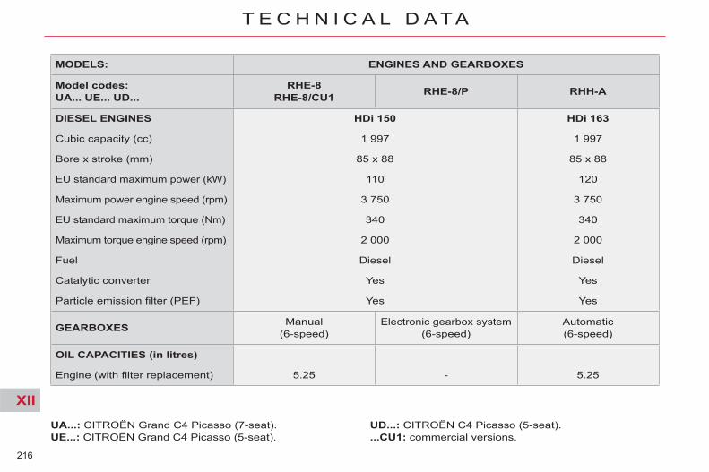
XII
216
T E C H N I C A L D A T A
MODELS: ENGINES AND GEARBOXES
Model codes: UA... UE... UD...
RHE-8 RHE-8/CU1 RHE-8/P RHH-A
DIESEL ENGINES HDi 150 HDi 163
Cubic capacity (cc) 1 997 1 997
Bore x stroke (mm) 85 x 88 85 x 88
EU standard maximum power (kW) 110 120
Maximum power engine speed (rpm) 3 750 3 750
EU standard maximum torque (Nm) 340 340
Maximum torque engine speed (rpm) 2 000 2 000
Fuel Diesel Diesel
Catalytic converter Yes Yes
Particle emission fi lter (PEF) Yes Yes
GEARBOXES Manual (6-speed)
Electronic gearbox system (6-speed)
Automatic (6-speed)
OIL CAPACITIES (in litres)
Engine (with fi lter replacement) 5.25 - 5.25
UA...: CITROËN Grand C4 Picasso (7-seat). UE...: CITROËN Grand C4 Picasso (5-seat).
UD...: CITROËN C4 Picasso (5-seat). ...CU1: commercial versions.

XII
217
T E C H N I C A L D A T A
WEIGHTS AND TOWED LOADS (in kg)
Diesel engines HDi 110
Gearboxes Manual Electronic gearbox system Model codes: UA... UE... UD... 9HZ-C 9HZ-H/P
- Unladen weight 1 530 - 1 484 - 1 489 1 539 - 1 494 - 1 499
- Kerb weight 1 605 - 1 559 - 1 564 1 614 - 1 569 - 1 574
- Payload 720 - 546 - 561 711 - 536 - 561
- Gross vehicle weight (GVW) 2 250 - 2 030 - 2 050 2 250 - 2 030 - 2 060
- Gross train weight (GTW)
on a 12 % gradient 3 130 3 130
- Braked trailer (within GTW limit)
on a 10 % or 12 % gradient 880 - 1 100 - 1 080 880 - 1 100 - 1 070
- Braked trailer * (with load transfer within GTW limit) 1 180 - 1 300 - 1 300 1 180 - 1 300 - 1 300
- Unbraked trailer 750 750
- Recommended nose weight 50 - 60 - 60 50 - 60 - 60
The GTW and towed load values indicated apply up to a maximum altitude of 1,000 metres; the towed load mentioned must be reduced by 10 % for each additional 1,000 metres of altitude. The speed of a towing vehicle must not exceed 100 km/h (approx. 60 mph) (comply with the legislation in force in your country). High ambient temperatures may result in a reduction in the performance of the vehicle in order to protect the engine; when the ambient temperature is higher than 37 °C, limit the weight towed.
* The weight of the braked trailer can be increased, within the GTW limit, on condition that the GVW of the towing vehicle is reduced by the same amount; warning, towing with a lightly loaded towing vehicle may have an adverse effect on its road holding.

XII
218
T E C H N I C A L D A T A
The GTW and towed load values indicated apply up to a maximum altitude of 1,000 metres; the towed load mentioned must be reduced by 10 % for each additional 1,000 metres of altitude. The speed of a towing vehicle must not exceed 100 km/h (approx. 60 mph) (comply with the legislation in force in your country). High ambient temperatures may result in a reduction in the performance of the vehicle in order to protect the engine; when the ambient temperature is higher than 37 °C, limit the weight towed.
WEIGHTS AND TOWED LOADS (in kg)
Diesel engines HDi 110
Gearboxes Manual Electronic gearbox system Electronic gearbox system Model codes: UA... UE... UD... 9HR-8 9HR-8/P 9HR-8/PS
- Unladen weight 1 490 - 1 430 - 1 430 1 510 - 1 470 - 1 420 1 520 - 1 480 - 1 430
- Kerb weight 1 565 - 1 505 - 1 505 1 585 - 1 545 - 1 495 1 595 - 1 555 - 1 505
- Payload 760 - 670 - 620 740 - 630 - 640 730 - 620 - 630
- Gross vehicle weight (GVW) 2 250 - 2 100 - 2 050 2 250 - 2 100 - 2 060 2 250 - 2 100 - 2 060
- Gross train weight (GTW)
on a 12 % gradient 3 130 3 130 3 130
- Braked trailer (within GTW limit)
on a 10 % or 12 % gradient 880 - 1 030 - 1 080 880 - 1 030 - 1 070 750 - 900 - 940
- Braked trailer * (with load transfer within GTW limit) 1 180 - 1 330 - 1 380 1 180 - 1 330 - 1 370 1 050 - 1 200 - 1 240
- Unbraked trailer 750 750 - 750 - 745 750
- Recommended nose weight 60 60 60
* The weight of the braked trailer can be increased, within the GTW limit, on condition that the GVW of the towing vehicle is reduced by the same amount; warning, towing with a lightly loaded towing vehicle may have an adverse effect on its road holding.

XII
219
T E C H N I C A L D A T A
The GTW and towed load values indicated apply up to a maximum altitude of 1 000 metres; the towed load mentioned must be reduced by 10 % for each additional 1 000 metres of altitude. The speed of a towing vehicle must not exceed 62 mph (approx 100 km/h) (comply with the legislation in force in your country). High ambient temperatures may result in a reduction in the performance of the vehicle in order to protect the engine; when the ambient temperature is higher than 37 °C, limit the weight towed.
WEIGHTS AND TOWED LOADS (in kg)
Diesel engines HDi 138
Gearboxes Electronic gearbox system Automatic Model codes: UA... UE... UD... RHJ-H/P RHR-J
- Unladen weight 1 620 - 1 582 - 1 581 1 650 - 1 611 - 1 640
- Kerb weight 1 695 - 1 657 - 1 656 1 725 - 1 686 - 1 715
- Payload 700 - 558 - 559 700 - 559 - 510
- Gross vehicle weight (GVW) 2 320 - 2 140 - 2 140 2 350 - 2 170 - 2 150
- Gross train weight (GTW)
on a 12 % gradient 3 620 - 3 590 - 3 540 3 550 - 3 520 - 3 550
- Braked trailer (within GTW limit)
on a 10 % or 12 % gradient 1 300 - 1 450 - 1 400 1 200 - 1 350 - 1 400
- Braked trailer * (with load transfer with GTW limit) 1 500 1 500
- Unbraked trailer 750 750
- Recommended nose weight 70 - 60 - 60 60
* The weight of the braked trailer can be increased, within the GTW limit, on condition that the GVW of the towing vehicle is reduced by the same amount; warning, towing with a lightly loaded towing vehicle may have an adverse effect on its road holding.

XII
220
T E C H N I C A L D A T A
* The weight of the braked trailer can be increased, within the GTW limit, on condition that the GVW of the towing vehicle is reduced by the same amount; warning, towing with a lightly loaded towing vehicle may have an adverse effect on its road holding.
The GTW and towed load values indicated apply up to a maximum altitude of 1 000 metres; the towed load mentioned must be reduced by 10 % for each additional 1 000 metres of altitude. The speed of a towing vehicle must not exceed 62 mph (approx 100 km/h) (comply with the legislation in force in your country). High ambient temperatures may result in a reduction in the performance of the vehicle in order to protect the engine; when the ambient temperature is higher than 37 °C, limit the weight towed.
WEIGHTS AND TOWED LOADS (in kg)
Diesel engines HDi 150 HDi 163
Gearbox es Manual Electronic gearbox system Automatic Type codes: UA... UE... UD... RHE-8 RHE-8/P RHH-A
- Unladen weight 1 613 - 1 580 - 1 610 - 1 637 - 1 601 - 1 614
- Kerb weight 1 688 - 1 655 - 1 685 - 1 712 - 1 676 - 1 689
- Payload 695 - 685 - 520 - 688 - 689 - 536
- Gross vehicle weight (GVW) 2 308 - 2 265 - 2 130 - 2 325 - 2 290 - 2 150
- Gross train weight (GTW)
on a 12 % gradient 3 508 - 3 515 - 3 530 - 3 525 - 3 490 - 3 550
- Braked trailer (within GTW limit)
on a 10 % or 12 % slope 1 200 - 1 250 - 1 400 - 1 200 - 1 200 - 1 400
- Braked trailer * (with load transfer with GTW limit) 1 400 - 1 500 - 1 600 - 1 500
- Unbraked trailer 750 - 750
- Recommended nose weight 70 - 60

XII
221
T E C H N I C A L D A T A
* If the maximum rear axle weight is exceeded when the vehicle is towing, the maximum speed is limited to 50 mph (80 km/h) as defi ned by point 2.7 of the EU Directive.
** If the the gross vehicle weight is exceeded when the vehicle is towing, the maximum speed is limited to 50 mph (80 km/h) as defi ned by point 2.7 of the EU Directive.
*** Maximum weight of the braked trailer within the GTW limit; warning, towing with a lightly loaded towing vehicle may have an adverse effect on its road holding.
The GTW and towed load values indicated apply up to a maximum altitude of 1,000 metres; the towed load mentioned must be reduced by 10 % for each additional 1,000 metres of altitude. High ambient temperatures may result in a reduction in the performance of the vehicle in order to protect the engine; when the ambient temperature is higher than 37 °C, limit the weight towed.
WEIGHTS AND TOWED LOADS (in kg) - COMMERCIAL VERSIONS
Petrol engines VTi 120 THP 155
Gearboxes Manual Electronic gearbox system Model codes: UA... UD...
UA5FS- 0/CU1 UD5FS-0/CU1
UA5FV-8/PCU1 UD5FV-8/PCU1
- Unladen weight 1 560 - 1 591 1 600 - 1 590 - Kerb weight 1 635 - 1 666 1 675 - 1 665 - Payload 630 - 624 620 - 620
- Gross vehicle weight (GVW) * 2 190 - 2 215 2 220 - 2 210
- Gross train weight (GTW)
on a 12 % gradient ** 3 290 - 3 415 3 420 - 3 410
- Braked trailer (within GTW limit)
on a 10 % or 12 % gradient *** 1 100 - 1 200 1 200 - 1 200
- Braked trailer (with load transfer within GTW limit) - -
- Unbraked trailer 750 - 750 750 - 750 - Recommended nose weight 70 - 60 70 - 60

XII
222
T E C H N I C A L D A T A
The GTW and towed load values indicated apply up to a maximum altitude of 1,000 metres; the towed load mentioned must be reduced by 10 % for each additional 1,000 metres of altitude. High ambient temperatures may result in a reduction in the performance of the vehicle in order to protect the engine; when the ambient temperature is higher than 37 °C, limit the weight towed.
* If the maximum rear axle weight is exceeded when the vehicle is towing, the maximum speed is limited to 50 mph (80 km/h) as defi ned by point 2.7 of the EU Directive.
** If the the gross vehicle weight is exceeded when the vehicle is towing, the maximum speed is limited to 50 mph (80 km/h) as defi ned by point 2.7 of the EU Directive.
*** Maximum weight of the braked trailer within the GTW limit; warning, towing with a lightly loaded towing vehicle may have an adverse effect on its road holding.
WEIGHTS AND TOWED LOADS (in kg) - COMMERCIAL VERSIONS
Diesel engines HDi 110 HDi 110 HDi 138 HDi 150
Gearboxes Manual Electronic gearbox system Manual Electronic
gearbox system Electronic
gearbox system Manual
Model codes UA... UD...
UA9HZ-C/CU1 UD9HZ-C/CU1
UA9HZ-H/PCU1 UD9HZ-H/PCU1
UA9HR-8/CU1 UD9HR-8/CU1
UA9HR-8/PCU1 UD9HR-8/PCU1
UARHJ-H/PCU1 UDRHJ-H/PCU1
UARHE-8/CU1 UDRHE-8/CU1
- Unladen weight 1 571 - 1 635 1 600 - 1 646 1 630 - 1 630 - 1 665 - 1 691 1 685 - 1 680 - Kerb weight 1 646 - 1 710 1 675 - 1 721 1 705 - 1705 - 1 740 - 1 766 1 760 - 1 755 - Payload 634 - 620 620 - 624 620 - 620 - 620 - 624 620 - 620
- Gross vehicle weight (GVW) * 2 205 - 2 255 2 220 - 2 270 2 250 - 2 250 - 2 285 - 2 315 2 305 - 2 300
- Gross train weight (GTW)
on a 12 % gradient ** 3 125 - 3 130 3 120 - 3 130 3 150 - 3 150 - 3 585 - 3 540 3 555 - 3 550
- Braked trailer (within GTW limit)
on a 10 % or 12 % gradient *** 920 - 875 900 - 860 900 - 900 - 1 300 - 1 225 1 250 - 1 250
- Braked trailer (with load transfer within GTW limit) - - - - - -
- Unbraked trailer 750 - 750 750 - 750 750 - 750 - 750 - 750 750 - 750 - Recommended nose weight 40 - 60 40 - 60 70 - 60 - 55 - 60 70 - 60

XII
223
T E C H N I C A L D A T A
* Depending on suspension and roof bars.
DIMENSIONS (IN METRES) Exterior (CITROËN Grand C4 Picasso and CITROËN C4 Picasso)
CITROËN Grand C4 Picasso
CITROËN C4 Picasso
A 2.730 2.730
B 4.590 4.470
C 0.990 0.990
D 0.870 0.750
E 1.510 1.510
F 1.540 1.540
G * 1.660 to 1.710 1.660 to 1.680
H 2.100 2.100
I 1.830 1.830

XII
224
T E C H N I C A L D A T A
A 0.930
B 0.960/0.980
C 0.880/1.000
D 1.610/1.870
E 0.930
F 1.140
G 1.120
H 1.170
Interior (CITROËN C4 Picasso)

XII
225
T E C H N I C A L D A T A
Interior (CITROËN Grand C4 Picasso)
E 0.880
F 1.070
G 1.160
H 1.170
A 0.920
B 0.990/1.000
C 1.030/1.160
D 1.800/2.060

XII
226
T E C H N I C A L D A T A
IDENTIFICATION MARKINGS
Various visible markings for identifi -cation of the vehicle. The vehicle type and the identifi ca-tion number are also indicated on the registration document. All CITROËN original replacement parts are available exclusively within the dealer network. For your safety and in order to re-main within the terms of the war-ranty, you are advised to use only CITROËN replacement parts.
A. Manufacturer’s label Located on the left-hand door centre pillar. 1. EU type approval number. 2. Vehicle Identifi cation Number (VIN). 3. Gross vehicle weight. 4. Gross train weight. 5. Maximum weight on front axle. 6. Maximum weight on rear axle.
B. Vehicle Identification Number (VIN)
Located on the bodywork and be-hind the windscreen.
C. Paint colour code Tyre reference Tyre pressures
Located on the driver's door front pillar.
Use the tyre pressures recom-mended by CITROËN. Check the tyre pressures regularly, when the tyres are cold. Never reduce the pressure of a hot tyre. When replacing tyres, it is essen-tial to use the tyre sizes that are recommended for your vehicle.

227
EMERGENCY OR ASSISTANCE CALL

228
CITROËN LOCALISED EMERGENCY CALL
In an emergency, press this button for more than2 seconds. Flashing of the green LED and a voice message confi rm that the call has been made to the CITROËN Emergency team * .
gg
Pressing this button again immediately cancels the request. The green LED goes off. A press (at any time) of more than 8 seconds on this button, cancels the request.
CITROËN LOCALISED ASSISTANCE CALL
When the ignition is switched on, thegreen LED comes on for 3 seconds indicating that the system is operating correctly.
If the orange LED fl ashes: there is asystem fault. If the orange LED is on continuously: thebackup battery must be replaced. In either case, contact a CITROËN.
Pressing this button again immediately cancels the request. The cancellation is confi rmed by a voice message.
Press this button for more than 2 seconds to requestassistance if the vehicle breaks down.A voice message confi rms that the call has been made * .
OPERATION OF THE SYSTEM
The green LED remains on (without fl ashing) when communication is established. It goes off at the end of communication.
If you purchased your vehicle outside the CITROËN dealer network, we invite you to have a dealer check the confi guration of these servicesand, if desired, modifi ed to suit your wishes. In a multi-lingual country, confi guration is possible in the offi cial national language of your choice.
This call is dealt with by the CITROËN Emergency team which receiveslocating information from the vehicle and can send a detailed alert to theappropriate emergency services. In countries in which the team is notoperational, or when the locating service has been expressly declined,the call is dealt with directly by the emergency services (112) without thevehicle location.
If an impact is detected by the airbag ECU, and independentlyof the deployment of any airbags, an emergency call is madeautomatically.
* These services are subject to conditions and availability. Consult a CITROËN dealer.
For technical reasons, particularly to improve the quality of Telematicservices to customers, the manufacturer reserves the right to carry out updates to the vehicle's on-board telematic system.

229
If an impact is detected by the airbag control unit, and independentlyof the deployment of any airbags, an emergency call is made automatically.The message "Deteriorated emergency call" associated with fl ashing of the orange indicator lamp indicates a malfunction. Contact a CITROËN dealer.
g
In an emergency, press the SOS button until an audible signal is heard and a "Confi rmation/Cancellation" screen is displayed (if valid SIM card inserted). A call is made to the CITROËN Emergency team which receives locating information from the vehicle and can send a detailed alert to the relevant emergency services. In countries in which the team is not operational, or when the locating service has been expressly declined, the call is sent to the emergency services (112).
Warning - the emergency call and the services are only active if the internal telephone is used with a valid SIM card. With a Bluetooth telephone and without a SIM card, these services are notoperational.
Press this button for access to CITROËN services.
Customer call
Select "Customer call" to requestany information about the CITROËN
q
marque.
Select "CITROËN Assistance" to make a roadside assistance call.
CITROËN Assistance
This service is subject to conditions and availability. Consult aCITROËN dealer. If you have purchased your vehicle outside the
j y
CITROËN dealer network, we invite you to have a dealer check the y p y
confi guration of these services and, if desired, modifi ed to suit your wishes.
EMERGENCY OR ASSISTANCE CALL USING NaviDrive CITROËN LOCALISED EMERGENCY CALL CITROËN LOCALISED ASSISTANCE CALL

230

231
NaviDrive
The NaviDrive is coded in such a way that it will onlyoperate in your vehicle.
For safety reasons, it is imperative that the driver carries out operations which require prolonged attention while the vehicle is stationary. When the engine is switched off and to prevent discharging of the battery, the NaviDrive may switch off after a few minutes.
MULTIMEDIA AUDIO/TELEPHONE SYSTEM JUKEBOX FUNCTION (10 GB)/GPS (EUROPE)
01 First steps 02 Voice commands and
steering mounted controls 03 Screen and main menu 04 Navigation - Guidance 05 Traffic information 06 Audio/Video 07 Telephone 08 Configuration 09 Screen menu map Frequently asked questions
p. p.
p. p. p. p. p. p. p. p.
232 233
235 239 249 251 260 264 265 271
CONTENTS

232
01
On/Off and Volumeadjustment.
Selection of the source:radio, Jukebox, CD and auxiliary (AUX, if activated on theConfi guration menu). Long press: CD copy tohard disk.
Selection of wavebands FM1,FM2, FMast, AM.
Cancellation of the current operation. Long press: return to the currentapplication.
Selection of the previous/nextMP3/USB/Jukebox folder.
Selection and confi rmation.
Audio option adjustments: front/rear,left/right balance, loudness, soundambiences.
SIM card slot.
Display the list of local radio stations, CD tracksor MP3/USB/Jukeboxfolders. Long press: update thelocal radio stations.
Display the main menu Automatic search for a lower/higher frequency.Selection of the previous/next CD, MP3, USB or Jukebox track.Long press: fast forward andbackward play.
Keypad for enteringdescriptions by successive presses.
Access to "CITROËN"services menu.
TA (Traffi c Announcement) function on/off. Long press: access to the PTY (radio Programme TYpes) mode.
Modifi cation of the screen display. Long press: reinitialisationof the system.
Long press on the SOS button: emergency call.
Selection of the display in the screen betweenmodes: TRIP, TEL, NAV and AUDIO.
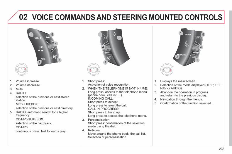
233
02
32
1 5
4
2
1
32
1 5
4
3
4
VOICE COMMANDS AND STEERING MOUNTED CONTROLS
1. Volume increase. 2. Volume decrease. 3. Mute.4. RADIO:
selection of the previous or next storedstation.MP3/JUKEBOX:selection of the previous or next directory.
5. RADIO: automatic search for a higher frequency. CD/MP3/JUKEBOX:selection of the next track. CD/MP3: continuous press: fast forwards play.
1. Short press: Activation of voice recognition. 2. WHEN THE TELEPHONE IS NOT IN USE: Long press: access to the telephone menu
(phone book, call list, ...). INCOMING CALL: Short press to accept. Long press to reject the call. CALL IN PROGRESS: Short press to hang up. Long press to access the telephone menu. 3. Personalisation: Short press: confi rmation of the selection
made using the dial. 4. Rotation: Move around the phone book, the call list. Selection of personalisation.
1. Displays the main screen.2. Selection of the mode displayed (TRIP, TEL,
NAV or AUDIO).3. Abandon the operation in progress
and return to the previous display. 4. Navigation through the menus. 5. Confi rmation of the function selected.

234
02
1
2
VOICE COMMANDS
VOICE COMMANDS AND STEERING MOUNTED CONTROLS
DISPLAYING THE LIST AND USING THEM
To display the list of available voice commands, press the voice recognition control to start the voice recognition,then say HELP or the voice recognition command.
For the same operation, press and hold the MENU button and select the"Voice commands list" function.
Press the voice recognition control tostart the voice recognition. Say the words one by one and wait for the audible confi rmation signal between each word. The list which follows is exhaustive.
LEVEL 1 LEVEL 2 LEVEL 3 radio memory
autostoreprevious/next list
1 to 6/*
cd player Jukebox (if activated) USB
previous/next track track number/track scan random play
directory (CD-MP3 inserted) list
1 to 250/* previous/next repeat help/what can I say/cancel
call/guide to "Pre-recorded description"
telephone last number voice boxvoice mail directory
"Pre-recorded description"
message display read directory
"Pre-recorded description"
navigation stop/resume zoom in/out view
* destination vehicle
traffi c info display read
display audio telephonetrip computer Navigation air conditioning
previous/next stop delete yes/no
for all level 1 and 2
* help/what can I say/cancel for all level 1, 2 or *
Voice commands list

235
03
°
SCREEN AND MAIN MENU
The system uses the complete and detailed NAVTEQ maps installed directly on the equipment's hard disk. Updates of the maps of the UK and of the other European countries, supplied by our partner NAVTEQ, are available from the CITROËN network.
This displays the following information, via the audio control panel: - time, - date, - ambient temperature (if there is a risk of ice, you are warned by a
message), - audio source displays (radio, CD, jukebox, ...), - telematic system displays (telephone, services, ...), - check of openings (doors, boot, ...), - warning messages (e.g.: "Fuel level low") and vehicle function status
messages (e.g.: "Auto lighting activated") displayed temporarily, - trip computer information, - GPS (Europe) satellite navigation system information.
> COLOUR SCREEN
Telephone
Orange
Time:Date:
Screen confi guration: refer to the section - Screen menu map.

236
03 SCREEN AND MAIN MENU
For maintenance of thescreen, the use of asoft, non-abrasive cloth(spectacles cloth) isrecommended without anyadditional product.
TRAFFIC INFORMATION:TMC information, messages.
MAP: orientation, details,display.
NAVIGATION GUIDANCE:GPS, stages, options.
VEHICLE DIAGNOSTICS:alert log, status of the functions.
VIDEO: activation,parameters.
CONFIGURATION: vehicle, display,time, languages, voice, auxiliarysocket (AUX) parameters.
TELEMATIC: telephone,directory, SMS.
AUDIO FUNCTIONS: radio,CD, Jukebox, options.
Long press on MENU: help.

237
03 SCREEN AND MAIN MENU DISPLAY ACCORDING TO THE CONTEXT
NAVIGATION (IF NAVIGATION IS IN PROGRESS):
Press the OK dial to access short-cut menus according to the display on thescreen.
resume/stop guidance1
1
1
1
divert route
route type
consult traffi c info
1zoom/scroll map
position info1
1
1
1
select as destination
select as stage
store this position
1exit map mode
1guidance option
IN "ZOOM/SCROLL" MODE
call list1
1
1
1
dial
phone book
voice mail
INTERNAL TELEPHONE
call list1
1
1
1
call
phone book
private mode/hands-free mode
1place call on hold/resume call
BLUETOOTH TELEPHONE
alert log1
1status of functions
VEHICLE DIAGNOSTICS

238
03 SCREEN AND MAIN MENU
copy USB to JBX/stop copy1
1
1
1
eject USB
activate/deactivate Introscan
activate/deactivate random play
1activate/deactivate repeat
USB
copy CD to JBX/stop copy1
1
1
1
activate/deactivate Introscan
activate/deactivate random play
activate/deactivate repeat
CD (MP3 OR AUDIO)
select playlist1
1
1
1
activate/deactivate Introscan
activate/deactivate random play
activate/deactivate repeat
JUKEBOX
enter a frequency1
1
1
1
activate/deactivate RDS
activate/deactivate REG mode
hide/display "Radio Text"
RADIO

239
04
1
2
3
4
5
6
7
8
NAVIGATION - GUIDANCE
Press the MENU button.
Turn the dial and select the Navigation Guidance function.
Press the dial to confi rm the selection.
Turn the dial and select the "Destination choice" function.
When the country has been selected, turn the dial and select the "Town" function.
Press the dial to confi rm the selection.
Turn the dial and select the "Enter an address" function.
Press the dial to confi rm the selection.
Tip: for a detailed global view of the menus available, refer to the "Screen menu map" part of this section. SELECTING A DESTINATION
Destination choice Town
Enter an address

240
04
9
10
11
12
13
14
15
NAVIGATION - GUIDANCE
Repeat steps 8 to 12 for the "Road" and "N°" functions. Turn the dial and select the letters of the town one by one confi rming each time by pressing the dial.
Select the "Store" function to record the address entered in a directory record and press the dial to confi rm the selection. The points of interest (POI) indicate all of the service locations in the vicinity (hotels, various businesses, airports, ...).
Select "OK" on the "Enter an address" page.
Press the dial to confi rm the selection.
Turn the dial and select OK.
To speed up the process, the "Post code" can beentered instead of the name of the "Town". Use the alphanumeric keypad to enter the letters and digits and "*" to correct (limit of 5 characters).
Press the dial to confi rm the selection.
Press the dial to confi rm the selection.
Paris
OK
OK
Store POI

241
04
1
2
3
5
6
7
8
94
NAVIGATION - GUIDANCE
ADDING A STAGE
Select "Strict" (the stage must be completed in order to continue to the next destination) or "Proximity" then press the dial to confi rm.
During guidance, press the MENUbutton.
Turn the dial and select the "Navigationguidance" function.
Press the dial to confi rm the selection.
Turn the dial and select the "Journey legs and route" function.
Press the dial to confi rm the selection.
Journey legs and route
Enter for example a new address.
When the new address has beenentered, select "OK" and press the dialto confi rm.
Enter an address
Select the "Add a stage" function (9 stages maximum) and press the dialto confi rm.
Add a stage
Select OK and press the dial to confi rmthe order of the stages.

242
04
1
2
3
5
6
7
8
4
GUIDANCE SPEECH SYNTHESIS
Press the MENU button.
The volume of the Risk Areas POI alerts can only be adjustedduring the alert using the volume adjustment control. During announcements, the volume of each speech synthesis function (guidance, traffi c information...) can be adjusted directly using the volume adjustment control.
Turn the dial and select the "Navigationguidance" function.
Press the dial to confi rm the selection.
Turn the dial and select the "Guidanceoptions" function.
Adjust speech synthesis
Deactivate
Press the dial to confi rm the selection.
Select the "Adjust speech synthesis"function and press the dial to confi rm.
Press the dial then adjust the volume of the speech synthesis or select the "Deactivate" function and press thedial to confi rm.
Select "OK" and press the dial toconfi rm.
OKGuidance options

243
04 NAVIGATION - GUIDANCE List of POI

244
04
1
2
3
5
4
NAVIGATION - GUIDANCE
Select "Map" and confi rm by pressing"OK".
Press the MENU button.
Select "Transport and automobiles"and confi rm by pressing "OK".
Select "Map details" and confi rm by pressing "OK".
The detailed procedure is available on the following website:"citroen.navigation.com".
UPDATING POIs DISPLAYING RISK AREAS POIs
Select "Risk areas" and confi rm by pressing "OK".
Map
Map details
Transport and automobiles
Risk areas

245
04
2
3
4
5
6
7
8
NAVIGATION - GUIDANCE
GUIDANCE OPTIONS
Turn the dial and select the "Navigation guidance" function.
Press the MENU button.
Turn the dial and select the "Guidanceoptions" function.
Press the dial to confi rm the selection.
Turn the dial and select the "Defi ne calculation criteria" function.
Press the dial to confi rm the selection.
Turn the dial and select, for example,the "Distance/time" function.
Press the dial to confi rm the selection.
The route presented depends directly on the guidance options. Changing these options may completely change the route.
Guidance options
Defi ne calculation criteria
Distance/time

246
04
9
10
11
12
1
2
3
SETTING RISK AREAS ALERT PARAMETERS
Turn the dial and select the "Traffi cinfo" function if you wish to receive the traffi c information announcements.
Press the dial to confi rm the selection.
Select "OK" and press the dial to confi rm.
Press the dial to confi rm the selection.
Turn the dial and select the "Setrisk area parameters" function, then press the dial to confi rm the warning message. Press the dial to confi rm theselection.
Repeat steps 1 to 5 of the guidance option.
These functions are only available if the risk areas have been downloaded and installed on the system.
Select: - visual warnings, - audible warnings with an
announcement duration (in seconds), - warn during guidance only, then
select OK and press the dial toconfi rm.
NAVIGATION - GUIDANCE
Tick this box for optimum operation of the traffi c information, diversions will be suggested.
The volume of the Risk Areas POI alerts can only be adjusted during the alert.
Traffi c info
OK
Set risk area parameters
OK
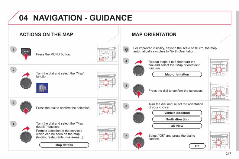
247
04
1
2
3
4
4
5
6
7
NAVIGATION - GUIDANCE
ACTIONS ON THE MAP
Turn the dial and select the "Map"function.
Press the MENU button.
Turn the dial and select the "Map details" function. Permits selection of the services which can be seen on the map (hotels, restaurants, risk areas...).
Press the dial to confi rm the selection.
MAP ORIENTATION
Press the dial to confi rm the selection.
Repeat steps 1 to 3 then turn the dial and select the "Map orientation" function.
Select "OK" and press the dial to confi rm.
Turn the dial and select the orientation of your choice.
For improved visibility, beyond the scale of 10 km, the map automatically switches to North Orientation.
Map details OK
Map orientation
3D view
North direction
Vehicle direction

248
04
2
3
4
5
6
7
NAVIGATION - GUIDANCE DISPLAYING THE MAP IN A WINDOW OR IN FULL SCREEN MODE
Turn the dial and select the "Map" function.
Press the MENU button.
Turn the dial and select the "Displaymap" function.
Press the dial to confi rm the selection.
Turn the dial and select the "Map inwindow" or "Full screen map" tab.
Press the dial to confi rm the selection.
Select "OK" and press the dial to confi rm
Display mapOK
Map in window
Full screen map

249
05
1
2
3
5
6
7
8
4
TRAFFIC INFORMATION CONFIGURING THE FILTERING OF TMC ANNOUNCEMENTS
Turn the dial and select the "Traffi cinformation" function.
Press the MENU button.
Press the dial to confi rm the selection.
Turn the dial and select the "Filter traffi c information" function.
Turn the dial and select the fi lter of your choice.
Select the "Geographic fi lter" functionand press the dial to confi rm.
The fi lters are independent and one replaces the other. We recommend: - a fi lter of 6 miles (10 km) around the vehicle in heavy traffi c, - a fi lter of 30 miles (50 km) around the vehicle or a fi lter on
the route for motorway journeys.
Select "OK" and press the dial toconfi rm.
The TMC (Traffi c Message Channel) messages provide informationrelating to the traffi c and the weather conditions, received in real time and communicated to the driver in the form of audible announcements andicons on the navigation map. The guidance system may then suggest a diversion route.
Press the dial to confi rm the selection.
Filter traffi c informationOK
Geographic fi lter
On the route
Around the vehicle
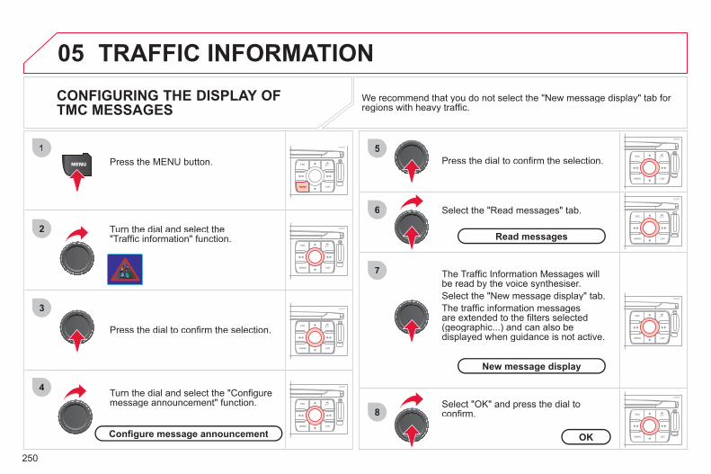
250
05
1
2
3
4
5
6
8
7
TRAFFIC INFORMATION CONFIGURING THE DISPLAY OF TMC MESSAGES
Turn the dial and select the"Traffi c information" function.
Press the MENU button.
Turn the dial and select the "Confi guremessage announcement" function.
Press the dial to confi rm the selection.
Select the "Read messages" tab.
Press the dial to confi rm the selection.
Select "OK" and press the dial to confi rm.
The Traffi c Information Messages will be read by the voice synthesiser. Select the "New message display" tab. The traffi c information messagesare extended to the fi lters selected (geographic...) and can also be displayed when guidance is not active.
We recommend that you do not select the "New message display" tab for regions with heavy traffi c.
Confi gure message announcement OK
Read messages
New message display

251
06
1
2
4
3
1
2
4
3
AUDIO/VIDEO RADIO
Press the BAND button to select awaveband: FM1, FM2, FMast, AM.
Press the SOURCE button severaltimes in succession and select RADIO.
Press the LIST button to displaythe list of stations received locally(60 maximum).To update this list, press for more than two seconds.
Press one of the buttons to carry out amanual search of the radio stations.
Briefl y press one of the buttons tocarry out an automatic search of the radio stations.
RDS
Select "Audio functions" then press"OK".
Press the MENU button.
RDS, if displayed, enables you to continue listening to the same stationby automatic retuning to alternative frequencies. However, in certain conditions, coverage of an RDS station may not be assured throughout the country as radio stations do not cover 100 % of the territory. This explains the loss of reception of the station during a journey.
Select "Activate RDS" then press "OK". RDS appears on the screen.
Select the "FM waveband preferences" function then press "OK".
The external environment (hills, buildings, tunnels, basement car parks, ...) may block reception, including in RDS mode. This is a normaleffect of the way in which radio waves are transmitted and does notindicate any failure of the audio equipment.
SELECTING A STATION
FM waveband preferences
Activate RDS

252
06
1
2
MP3 CD
The MP3 format, an abbreviation of MPEG 1.2 & 2.5 Audio Layer 3, is an audio compression standard which permits the recording of several tens of music fi les on a single disc.
Empty CDs are not recognised and may damage the system.
It is advisable to restrict fi le names to 20 characters without usingspecial characters (e.g. " ? ; ù) to avoid any playing or displaying problems.
The audio system will only play fi les with the extension ".mp3" witha sampling rate of 22.05 KHz or 44.1 KHz. No other type of fi le(.wma, .mp4, .m3u...) can be played.
If the player already contains a disc, press the SOURCE button several times in succession and select CD to listen to it.
Insert circular compact discs only. Some anti-piratingsystems, on original discs or CDs copied usinga personal recorder, may generate malfunctionsregardless of the quality of the original player. Insert an audio CD or an MP3 compilation in the player,play begins automatically.
The play and display of an MP3 compilation may depend on the disc burning software and/or the settings used. We recommend use of the ISO 9660 fi le system format.
Press one of the buttons to select atrack on the CD. Press the LIST button to display the listof tracks on the CD or of the folders of the MP3 compilation.
CD PLAYING A CD OR AN MP3 COMPILATION INFORMATION AND ADVICE
In order to be able to play a recorded CDR or CDRW, when recording, the ISO 9660 level 1.2 or Joliet fi le format isrecommended. If the disc is recorded in another format, it may not be playedcorrectly.It is recommended that the same recording format is always used for an individual disc, with as low a speed as possible (4x maximum) for optimum sound quality. In the particular case of a multi-session CD, the Joliet format is recommended.

253
06
1
2
1
AUDIO/VIDEO
USING THE USB PORT *
USB memory stick (1.1, 1.2 and 2.0):- the USB memory sticks must be in FAT or
FAT 32 format (NTFS not supported), - navigation through the fi le base is by means
of the steering mounted controls.
The audio fi les are transmitted from a USB memorystick to your audio system, to be listened to via the vehicle's speakers.Do not connect a hard drive or USB equipment other than USB memory sticks in FAT 16 or FAT 32 format (NTFS not supported). This could damage your installation.
Do not connect a hard drive or USB equipment other than USB memory sticks in FAT 16 or FAT 32 format (NTFS not supported).This could damage your installation.
Connect the memory stick to the port, directly or using a lead. If the audio equipment is switched on, the USB source is detected as soon as it is connected. Play begins automatically after a delay which depends onthe capacity of the USB memory stick.The fi le formats recognised are .mp3 (mpeg1 layer 3 only).
The list of compatible equipment is available from CITROËN dealers.
CONNECTING A USB MEMORY STICK
* Availability according to vehicle.

254
06
1
2
4
3
5
1
2
3
AUDIO/VIDEO PLAYING AN MP3 USB MEMORY STICK
If another source is being played,press the SOURCE button several times in succession and select "USB"to play it.
Connect a USB memory stick to the port provided.
To eject the USB memory stick, use the short-cut menu (press OK)or press the MENU button, select "Audio functions", "USB", then select "Eject USB". The play and display of an MP3 compilation may depend on the fi le format used.
Select "USB" and press the dial toconfi rm.
Insert a USB memory stick in thespace provided and press the MENUbutton.
JUKEBOX
USB
Select "Complete disc" to copy theentire USB memory stick and press thedial to confi rm.
Complete disc
Select "Copy USB to jukebox" andpress the dial to confi rm.
Copy USB to jukebox
Select "Audio functions" and press the dial to confi rm.
Press one of the buttons to select atrack on the USB memory stick. Press the LIST button to display the list of folders on the MP3 USB memorystick.
COPYING AN MP3 USB MEMORY STICK ONTO THE HARD DISK
In order to be read, the USB memory stick must be formattedFAT 16 or 32. The player only reads USB memory sticks.

255
06
1
2
4
3
6
5
COPYING A CD ONTO THE HARD DISK
Select "Audio functions" then selectCD and press the dial to confi rm.
Insert an audio CD or an MP3compilation and press the MENU button.
Select "Copy CD to jukebox" and press the dial to confi rm.
Select the letters one by one and select "OK" to confi rm.
The "Auto creation" tab automatically copies the CD by default into an album of the type "album n°...".
The audio or MP3 CD is copied onto the hard disk. Copying may take up to 20 minutes depending on the length the CD. While copying is in progress, it is not possible to listen to albumspreviously copied to the hard disk or to CDs.
If it is not an MP3 CD, the Jukebox automatically compresses theCD in MP3 format. The compression may take approximately20 minutes depending on the length the CD. During thiscompression phase, it is possible to listen to the CD or to albums previously copied to the hard disk.
A long press on the SOURCE button starts copying of the CD.
Audio functions
OK
Copy CD to jukebox
Select "Complete CD" to copy the entire CD and press the dial to confi rm.
Complete CD
To stop the copy, repeat points 2 and 3.Select "Stop copy" and press the dial to confi rm.
Stop copy
It is not possible to copy fi les from the Jukebox to a CD. The "Stop the CD copy" action does not delete the fi les which have already been transferred onto the jukebox hard disk.

256
06
1
2
3
4
1
2
3
AUDIO/VIDEO
Select "Audio functions" and press the dial to confi rm.
Press the MENU button.
RENAMING AN ALBUM
Select the "Jukebox" function andpress the dial to confi rm.
Jukebox
Select the "Jukebox management"function and press the dial to confi rm.
Jukebox management
Press the LIST button.
Press the SOURCE button severaltimes in succession and select the"Jukebox" function.
Turn the dial to select the fi les.
LISTENING TO THE JUKEBOX
Jukebox
Press the ESC button to return to the fi rst fi le level.

257
06
5
6
7
8
AUDIO/VIDEO
Select the "Rename" tab and press the dial to confi rm.
Select the album to be renamed andpress the dial to confi rm.
Use the alphanumeric keypad to enter the letters of the album title one by one.
Turn the dial and select the letters of the album title one by one confi rming each time by pressing the dial.
Rename To rename the tracks of an album, follow the same procedure,selecting the tracks to be renamed. Use the ESC button to exit from the list of tracks.
Select "OK" and press the dial toconfi rm.
OK
Select the "Delete" function to delete an album or a track from the Jukebox.
Delete

258
06
1
2
AUDIO/VIDEO
Connect the portable device (MP3 player…) to the audiosockets (white and red, RCA type) located in the glovebox using a suitable audio cable (JACK or RCA).
Press the MENU button then select the "Confi guration" function,then "Sounds", then "Activate auxiliary source" to activate theNaviDrive audio/telephone auxiliary input.
It is not possible to copy the fi les onto the hard disk via the auxiliary input.
Press the SOURCE button severaltimes in succession and select AUX.
USING THE AUXILIARY INPUT (AUX) AUDIO (JACK/RCA) CABLE NOT SUPPLIED
Display and control is on the portable device.

259
06
1
2
4
3
7
5
6
AUDIO/VIDEO
VIDEO MENU
Turn the dial and select the "Video"function.
After connecting the video equipment,press the MENU button.
Press the dial to confi rm the selection.
Turn the dial and select the "Activatevideo mode" function to activate/deactivate the video.
Press the dial to confi rm the selection.
Turn the dial and select the "Video parameters" function to set the displayformat, the brightness, the contrast and the colours.
Videos can only be displayed when stationary.
Pressing the DARK button disconnects display of the video.
You can connect video equipment (camcorder, digital camera, DVD player...)to the three audio/video sockets, located in the glove box.
Pressing the SOURCE button several times in succession permits the selection of an audio source other than that of the video.
Press the dial to confi rm the selection.
Activate video mode
Video parameters

260
07
1
2
1
2
3
INTERNAL TELEPHONE
Install the SIM card in the holder andthen insert it in theslot.
Open the holder by pressing the buttonusing the tip of a pen.
Your SIM card must be installed and removed with the NaviDrive audio and telematics system switched off and the ignition off.
To remove the SIM card, repeat step 1.
Confi rm the PIN code by pressing the # button.
Enter the PIN code on the keypad.
When entering your PIN code, tick the "Store PIN" tab to gain access to the telephone without having to enter this code when it is used subsequently.
INSTALLING YOUR SIM CARD (NOT SUPPLIED) ENTERING THE PIN CODE
PIN code

261
07
1
2
3
4
BLUETOOTH TELEPHONE CONNECTING A BLUETOOTH TELEPHONE
Activate the telephone's Bluetooth function. The last telephone connected is reconnectedautomatically.
For reasons of safety, the driver should only carry out operations which require prolonged attention when the vehicle is stationary (pairing the Bluetooth mobile telephone to the hands-free kit).
Press the MENU button, select"Telematics", then "Bluetoothfunctions". Press the dial to confi rmeach operation.
To fi nd and change the name of the CITROËN audio/telephone,repeat step 2 then select "Change the name of the audio/telephone".
Select "Bluetooth activation mode", then "Activated and visible". Press thedial to confi rm each operation.
On your telephone, select the name of the CITROËN audio/telephone. Enter the
y p ,
authentication code (0000 by default).
The services offered by the telephone depend on the network, the SIM card and the compatibility of the Bluetooth equipment used. Refer to your telephone's manual and your operator to check which services you have access to. A list of mobile telephones which offer the best range of servicesis available from dealers.

262
07 BLUETOOTH TELEPHONE CONNECTING A BLUETOOTH TELEPHONE
To change the telephone connected, repeat step 2 then select "Listof matched peripheral equipment" and press OK to confi rm. Thelist of previously connected telephones (10 maximum) appears. Select the telephone of your choice, confi rm, then select "Connect"and press the dial to confi rm.
To change the authentication code, repeat step 2 then select"Authentication code" and save the code of your choice.
The call list consists of calls made from the vehicle's telephone only.
Once the telephone has been connected, the system can synchronise the address book and the call list. Repeat step 2then select "Phone book synchronisation mode". Select thesynchronisation of your choice and press the dial to confi rm. The synchronisation may take a few minutes.

263
07
1
2
4
3
6
5
USING THE TELEPHONE
CALLING A CONTACT
Select "Call list" or "Phone book" and press "OK". Select thenumber required and confi rm to make the call.
Press the PICK UP button to displaythe telephone short-cut menu.
Dial the telephone number of your contact using the alphanumeric keypad.
Press the dial to confi rm the selection.
Press the HANG UP button to end the call.
Press the PICK UP button to call thenumber dialled.
Press the HANG UP button to reject a call.
Press the PICK UP button to accept a call.
ACCEPTING OR REJECTING A CALL Turn the dial and select the "Dial" function.
Dial
To select the telephone used, press MENU, then select "Telematics", then "Bluetooth functions", then "Bluetooth activation mode". Then select: - "Deactivated": to use the internal telephone, - "Activated and visible": to use the Bluetooth telephone, visible to all
telephones, - "Activated and not visible": to use the Bluetooth telephone, not visible
to other telephones, it is not possible to match a new telephone.
Press the end of the steering wheel stalk for morethan 2 seconds to access the telephone menu: calls log, directory, voice mailbox.

264
08
1
2
3
4
5
6
7
8
CONFIGURATION
SETTING THE DATE AND TIME
Turn the dial and select the"Confi guration" function.
Press the MENU button.
Press the dial to confi rm the selection.
Turn the dial and select the "Displayconfi guration" function.
Press the dial to confi rm the selection.
Turn the dial and select the "Set dateand time" function.
Adjust the settings one by oneconfi rming by pressing the dial. Next select the "OK" tab on the screen then confi rm.
Press the dial to confi rm the selection.
The "Confi guration" function gives access to the colour, brightness and units settings and to voice commands.
Display confi guration OK
Set date and time
This adjustment must be carried out whenever the battery has been disconnected.
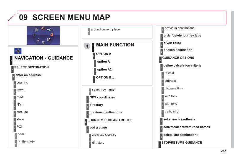
265
09 SCREEN MENU MAP
MAIN FUNCTION
OPTION A
OPTION B...
option A1
option A2
1
2
3
2
3
NAVIGATION - GUIDANCE
enter an address
country:
store
SELECT DESTINATION
town:
road:
N°/_:
curr. loc
POI
near
on the route
around current place
1
2
3
4
4
4
5
5
4
4
4
5
4
search by name5
GPS coordinates3
directory3
previous destinations3
add a stage
JOURNEY LEGS AND ROUTE
enter an address
directory
previous destinations
order/delete journey legs
divert route
4
3
2
4
4
3
3
chosen destination3
defi ne calculation criteria
fastest
traffi c info
GUIDANCE OPTIONS
shortest
distance/time
with tolls
with ferry
2
3
4
4
4
4
4
4
set speech synthesis3
activate/deactivate road names3
delete last destinations3
STOP/RESUME GUIDANCE 2

266
09 SCREEN MENU MAP
MAP
vehicle direction
MAP ORIENTATION
1
2
3
supermarkets, shopping
culture, tourism and shows
4
3
north direction3
3D view3
administration and safety
MAP DETAILS
town halls, town centre
universities, colleges
hospitals
hotels, restaurants and shops
4
3
2
4
4
3
hotels
restaurants
vineyards
business centres
4
4
4
4
culture and museums
casinos and nightlife
cinemas and theatres
tourism
shows and exhibitions
4
4
4
4
4
sports and open air centres
sports centres
theme parks
golf courses
skating rinks, bowling alleys
winter sports resorts
parks, gardens
3
4
4
4
4
4
4
transport and automobile
airports, ports
3
4
stations, bus stations 4
full screen map
DISPLAY MAP2
3
map in window3
MOVE THE MAP/FOLLOW VEHICLE 2
MAP DATABASE DESCRIPTION2
vehicle rental
lay-bys, car parks
service stations, garages
4
4
4
TRAFFIC INFORMATION
READ MESSAGES
1
2
geographic fi lter3
store all messages3
store messages3
FILTER TRAFFIC INFORMATION 2

267
09 SCREEN MENU MAP around the vehicle
on the route
road information
4
4
3
traffi c information
road closure
size limit
road condition
4
4
4
4
weather and visibility
urban/city information
4
3
parking
public transport
demonstrations
4
4
4
read messages3
new message display3
CONFIGURE MESSAGE ANNOUNCEMENT2
automatic TMC3
manual TMC3
list of TMC stations3
SELECT TMC STATION2
AUDIO FUNCTIONS
enter a frequency
RADIO FAVOURITES
1
2
3
activate/deactivate RDS mode3
activate/deactivate regional mode3
display/hide radio text3
activate/deactivate Introscan (SCN)
CD, USB, JUKEBOX FAVOURITES 2
3
activate/deactivate Random mode (RDM)3
activate/deactivate Repeat (RPT)3
activate/deactivate display of CD info3
copy CD to Jukebox
CD
copy complete CD
multiple selection
current album
4
3
2
4
4
current track4
eject CD3
copy USB to Jukebox
USB
complete disc
multiple selection
current album
4
3
2
4
4
current track4
eject USB3
jukebox management
JUKEBOX2
3

268
09
playlist management
hi-fi (320 kbps)
delete jukebox data
Jukebox status
high (192 kbps)
normal (128 kbps)
3
3
3
4
4
4
TELEMATICS
call list
CALL
1
2
3
dial3
directory3
mailbox3
services3
customer contact centre4
CITROËN assistance
CITROËN service
messages received
4
4
4
managing directory fi les3
DIRECTORY 2
consult or modify a fi le
add a fi le
delete a fi le
4
4
4
confi gure directory
delete all fi les
3
4
select a directory
name directory 4
4
fi le transfer
select starting directory
3
4
exchange by infrared
send all records
send one record
receive by infrared
5
5
5
4
exchange with SIM card
send all records to SIM
send one record to SIM
5
5
4
receive all SIM fi les
receive a SIM fi le
5
5
exchange with Bluetooth 4
read received text messages
TEXT MESSAGES (SMS)2
3
send a text message3
write a text message3
delete list of text messages3
network
TELEPHONE FUNCTIONS 2
3
network search mode 4
SCREEN MENU MAPjukebox confi guration
3

269
09automatic mode
manual mode
5
5
length of calls
networks available
3
4
reset 4
manage PIN code3
activate/deactivate
save PIN code 4
4
modify PIN code 4
call options3
confi gure calls
display my number
automatic reply after x ring(s)
5
5
4
ring options
for voice calls
for text messages (SMS)
5
5
4
calls diversion to mailbox n°
text message ring 6
3
delete calls log3
activation mode3
BLUETOOTH FUNCTIONS2
deactivated
activated and visible
activated and not visible
4
4
4
list of matched peripheral equipment3
change the name of the audio/telephone3
authentication code3
phone book synchronisation mode3
no synchronisation
view telephone phone book
view SIM card phone book
4
4
4
view all phone books 4
CONFIGURATION
choose colour
DISPLAY CONFIGURATION
1
2
3
adjust luminosity3
set date and time3
select units3
voice commands setting
SOUND2
3
speech synthesis setting3
guidance instructions volume
other message volume
4
4
select female/male voice 4
activate/deactivate auxiliary source3
SELECT LANGUAGE2
DEFINE VEHICLE PARAMETERS * 2
SCREEN MENU MAP
* The parameters vary according to vehicle.

270
09
VIDEO
display formats
VIDEO PARAMETERS
1
2
3
adjust luminosity3
set colours3
set contrasts3
ACTIVATE VIDEO MODE 2
VEHICLE DIAGNOSTICS
STATUS OF FUNCTIONS *
1
2
ALERT LOG 2
RESET TYRE PRESS. DETEC. SYS. *2
GPS COVERAGE
UNIT DESCRIPTION
1
2UNIT BACKUP POWE R
2
2
VOICE COMMANDS LIST 1
SERVICES CONFIGURATION 1
NAVIGATION DEMONSTRATION 1
Press the MENU button for more than 2 seconds to access the following fl ow chart.
Press the Music button several times in succession to access the followingsettings.
MUSICAL AMBIENCE
SCREEN MENU MAP
BASS
TREBLE
LOUDNESS CORRECTION
FR - RR BALANCE
Display short cuts version 8.2
LH - RH BALANCE
AUTO VOLUME CORRECTION
Each audio source (Radio, CD, MP3,Jukebox) has its own separate settings.
* The parameters vary according to the vehicle.
AUDIO/TELEPHONE DIAGNOSTICS

271
FREQUENTLY ASKED QUESTIONS
QUESTION ANSWER SOLUTION
There is a difference in sound quality betweenthe different audiosources (radio, CD...).
For optimum sound quality, the audio settings (Volume, Bass, Treble, Ambience, Loudness) can be adapted to the different sound sources,which may result in audible differences when changing source (radio,CD...).
Check that the audio settings (Volume, Bass, Treble, Ambience, Loudness) are adapted tothe sources listened to. It is advisable to setthe AUDIO functions (Bass, Treble, Front-Rear Balance, Left-Right Balance) to the middle position, select the musical ambience "None" and set the loudness correction to the "Active" position in CD mode or to the "Inactive" position in radio mode.
The CD is ejected automatically or is not played by the player.
The CD is inserted upside down, is unplayable, does not contain any audio data or contains an audio format which the player cannot play.
The CD is protected by an anti-pirating protectionsystem which is not recognised by the audio equipment. - Check that the CD is inserted in the player the
right way up. - Check the condition of the CD: the CD cannot
be played if it is too damaged. - Check the content in the case of a recorded
CD: consult the advice in the Audio section. - The audio equipment's CD player does not
play DVDs. - Due to inadequate quality, certain recorded
CDs will not be played by the audio system.
The CD player sound ispoor.
The CD used is scratched or of poor quality. Insert good quality CDs and store them in suitable conditions.
The audio equipment settings (bass, treble, ambiences) are unsuitable. Set the treble or bass level to 0, without selectingan ambience.
The table below groups together the answers to the most frequently asked questions.

272
QUESTION ANSWER SOLUTION
The stored stations donot function (no sound, 87.5 Mhz is displayed...)
An incorrect waveband is selected. Press the BAND AST button to return to the waveband (AM, FM1, FM2, FMAST) on which thestations are stored.
The quality of receptionof the radio station listened to graduallydeteriorates or the stored stations do not function(no sound, 87.5 Mhz is displayed...).
The vehicle is too far from the transmitter used by the station listenedto or there is no transmitter in the geographical area through which the vehicle is travelling.
Activate the RDS function to enable the system to check whether there is a more powerful transmitter in the geographical area.
The environment (hills, buildings, tunnels, basement car parks...) block reception, including in RDS mode.
This phenomenon is normal and does not indicate a failure of the audio equipment.
The aerial is absent or has been damaged (for example when goingthrough a car wash or into an underground car park).
Have the aerial checked by a CITROËN dealer.
Sound cut-outs of 1 to2 seconds in radio mode.
During this brief sound cut-out, the RDS searches for any frequency permitting better reception of the station.
Deactivate the RDS function if the phenomenon is too frequent and always on the same route.
With the engine off, the audio equipment switches off after a few minutes of use.
When the engine is switched off, the audio equipment operating timedepends on the battery charge. The switch-off is normal: the audio equipment switches to economy mode and switches off to prevent discharging of the vehicle's battery.
Start the vehicle's engine to increase the batterycharge.
TRAFFIC INFO is selected. However,certain traffi c jams along the route are notindicated in real time.
On starting, it is several minutes before the system begins to receive thetraffi c information.
Wait until the traffi c information is being received correctly (displaying of the traffi c information symbols on the map).
In certain countries, only major routes (motorways, ...) are listed for thetraffi c information.
This phenomenon is normal. The system isdependent on the traffi c information available.
The time taken to calculate a route sometimes seems longer than usual.
The performance of the system may slow down temporarily if a CD isbeing copied onto the Jukebox at the same time as a route is being calculated.
Wait until the CD has been copied or stop the copying before starting the guidance function.

273
ANSWER SOLUTION
Does the emergency call function work without a SIM card?
Certain national regulations impose the presence of a SIM card in order to make an emergency call.
Insert a valid SIM card in the slot on the system.
The altitude is not displayed.
On starting, the initialisation of the GPS may take up to 3 minutes toreceive more than 4 satellites correctly.
Wait until the system has started up completely. Check that there is a GPS coverage of at least4 satellites (long press on the MENU button, then select AUDIO/TELEPHONE DIAGNOSTICS, thenGPS COVERAGE).
Depending on the geographical environment (tunnel, ...) or the weather, the conditions of reception of the GPS signal may vary.
This phenomenon is normal. The system isdependent on the conditions of reception of the GPS signal.
My SIM card is not recognised.
The system accepts 3.3 V SIM cards, the old 5 V and 1.8 V SIM cardsare not recognised.
Contact your telephone operator.
The route is notcalculated successfully.
The exclusion criteria may confl ict with the current location (exclusion of toll roads on a motorway with tolls).
Check the exclusion criteria.
There is a long wait after inserting a CD.
When a new medium is inserted, the system reads a certain amount of data (folder, title, artist, etc.). This may take a few seconds.
This phenomenon is normal.
I cannot connect myBluetooth telephone.
The telephone's Bluetooth function may be switched off or the equipmentmay not be visible.
- Check that your telephone's Bluetoothfunction is switched on.
- Check that your telephone is visible.

274

275
The MyWay is protected in such a way that it will onlyoperate in your vehicle.
Certain functions described in this handbook willbecome available during the year.
MyWay
For safety reasons, the driver must carry out operations which require prolonged attention while the vehicle is stationary. When the engine is switched off and to prevent discharging of the battery, the MyWay switches off following the activation of the Energy Economy mode.
MULTIMEDIA AUDIO SYSTEM/BLUETOOTH TELEPHONE SATELLITE NAVIGATION SYSTEM FOR EUROPE BY SD CARD
01 First steps
CONTENTS
02 Steering mounted controls 03 General operation 04 Navigation - Guidance 05 Traffic information 06 Radio 07 Music media players 08 Bluetooth telephone 09 Configuration 10 Screen menu map
p. p. p. p. p. p. p. p. p. p.
Frequently asked questions p.
276 277 278 281 289 291 292 295 298 299 303
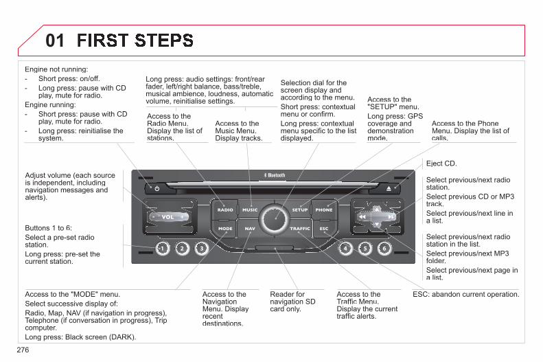
276
01Engine not running:- Short press: on/off.- Long press: pause with CD
play, mute for radio. Engine running: - Short press: pause with CD
play, mute for radio. - Long press: reinitialise the
system.
Access to theRadio Menu.Display the list of stations.
Access to theMusic Menu. Display tracks.
Long press: audio settings: front/rear fader, left/right balance, bass/treble,musical ambience, loudness, automatic volume, reinitialise settings.
Selection dial for thescreen display and according to the menu.Short press: contextual menu or confi rm. Long press: contextual menu specifi c to the listdisplayed.
Access to the"SETUP" menu. Long press: GPS coverage anddemonstrationmode.
Access to the PhoneMenu. Display the list of calls.
Eject CD.
Select previous/next radio station. Select previous CD or MP3track.Select previous/next line in a list.
Select previous/next radio station in the list. Select previous/next MP3 folder.Select previous/next page in a list.
ESC: abandon current operation. Access to theTraffi c Menu. Display the current traffi c alerts.
Reader for navigation SDcard only.
Access to theNavigation Menu. Displayrecent destinations.
Access to the "MODE" menu. Select successive display of:Radio, Map, NAV (if navigation in progress), Telephone (if conversation in progress), Tripcomputer. Long press: Black screen (DARK).
Buttons 1 to 6: Select a pre-set radiostation. Long press: pre-set the current station.
Adjust volume (each source is independent, including navigation messages andalerts).

277
02
32
1 5
4
2
1
32
1 5
4
3
4
STEERING MOUNTED CONTROLS
1. Volume increase. 2. Volume decrease. 3. Successive presses mute/restore the sound.4. Rotation - associated with a pop-up.
Radio - access the 6 stored stations: next or previous.Music players: previous/next track.
5. Radio: next station. Music players: next track.
1. Press. Repeat the current spoken navigation
instruction. 2. Short press to make a telephone call. Pick up/Hang up. Access the telephone menu. Display the call list. Long press to reject an incoming call. 3. Personalisation. Short press to confi rm the choice made
using the dial. 4. Rotation. Scroll through the call list in the phone book. Personalisation selection.
1. Short press: provides access to the menu according to the display on the screen.
2. Successive presses: provides access according to the current display on the screen.MAP/NAV (if navigation is in progress), TEL (if a conversation is in progress), RADIO or MEDIA in progress, Trip computer.Long press: switch to black screen - Dark (night driving).Touching a control restores the display.
3. ESC: abandon the current operation. 4. Rotation: selects the access to the short-cut
menus according to the current display. 5. Confi rms the choice displayed on the
screen.

278
03 GENERAL OPERATION
For a detailed global view of the menus available, refer to the"Screen menu map" section.
Press the MODE button several times in succession for access to the following menus:
For cleaning the screen, the use of a soft, non-abrasive cloth (spectacles cloth) is recommended, with no additional product.
RADIO / MUSIC MEDIA PLAYERS
TELEPHONE(If a conversation is in progress)
FULL SCREEN MAP
NAVIGATION (If guidance is in progress)
SETUP: system language * , date and time * , display,vehicle settings * , unit and system settings, "Demo mode".
TRAFFIC:TMC information and messages.
* Available according to model.
TRIP COMPUTER

279
03
A press on the OK dial gives access to short-cut menus according to the displayon the screen.
DISPLAY ACCORDING TO THE CONTEXT
NAVIGATION (IF GUIDANCE IS IN PROGRESS):
TRIP COMPUTER:
Abort guidance
Repeat advice
Block road
Route info
Show destination
Trip info
Route type
Avoid
Satellites
Zoom/Scroll
Voice advice
Route options
Alert log
Status of functions
1
2
3
3
2
1
1
1
3
1
1
1
1
2
TELEPHONE:
End call
Hold call
Dial
DTMF-Tones
Private mode
Micro off
1
1
1
1
1
1

280
03 GENERAL OPERATION DISPLAY ACCORDING TO THE CONTEXT
FULL SCREEN MAP:
Abort guidance / Resume guidance
Set destination
POIs nearby
Position info
Map settings
Zoom/Scroll
1
1
1
1
1
1
RADIO:
In FM mode
Traffi c info (TA)
RDS
Radiotext
Regional prog.
In AM mode
AM
TA
Refresh AM list
FM
1
2
1
2
2
2
2
2
2
2
MUSIC MEDIA PLAYERS:
Traffi c info (TA)
Play options
Normal order
Random track
Repeat folder
Select music
Scan
1
1
2
2
2
2
1

281
04
1
2
3
5
6
4
NAVIGATION - GUIDANCE
SELECTING A DESTINATION
Press the NAV button again or select the Navigation Menu function andpress the dial to confi rm.
Select the "Destination input" function and press the dial toconfi rm.
Press the NAV button.
Select the letters of the town oneby one confi rming each time by pressing the dial.
Once the country has been selected,turn the dial and select the townfunction. Press the dial to confi rm.
Insert the SD card in the front panel reader and leave it there to use theNavigation functions. The navigation SD card data must not be modifi ed.Map data updates are available from CITROËN dealers.
A pre-set list (by entering the fi rst few letters) of the towns in thecountry selected can be accessed via the LIST button on the virtualkeypad.
Select the "Address input" function and press the dial to confi rm.
The list of the last 20 destinations appears under the NavigationMenu function.
Navigation Menu
Destination input
Address input

282
047
8
9
To clear a destination; from steps 1 to 3, select "Choose from last destinations". A long press on one of the destinations displays a list of actions from which you can select: Delete entry Delete list
Repeat steps 5 to 7 for the "Street" and "House number" functions.
Turn the dial and select OK. Press the dial to confi rm.
Select the "Save to address book" function to record the address entered in a directory fi le. Press the dial to confi rm the selection.MyWay allows up to 500 contact fi les to be recorded.
To speed up the process, the post code can be entered directly after selecting the "Postal code" function. Use the virtual keypad to enter the letters and digits.
Then select "Start route guidance"and the press the dial to confi rm.
During guidance, pressing this buttonrepeats the last guidance instruction.
Map settings You can zoom in/zoom out on the map using the dial. It is possible to move the map or select its orientation via the short-cut menu of the FULL SCREEN MAP. Press MODE until the map is displayed full screen. Press the dialthen select "Map settings". Select "2.5D Map" or "2D Map" and in the latter case, select "North Up" or "Heading Up".
Select the route type: "Fast route", "Short route" or "Optimized route" and press the dialto confi rm. It is also possible to select a destination via "Choose from address book" or "Choose from last destinations".
Choose from last destinationsChoose from address book
Start route guidance
NAVIGATION - GUIDANCE

283
04
1
2
3
5
4
NAVIGATION - GUIDANCE SETTING AND NAVIGATING TO MY "HOME ADDRESS"
Press the NAV button twice to display the Navigation Menu.
To be set as the "Home address", an address must fi rst be entered in the address book, for example from "Destinationinput"/"Address input" then "Save to address book".
Select "Address book" and confi rm. Then select "Search entry (complete address book)" and confi rm.
Select "Destination input" and confi rm. Then select "Choose from addressbook" and confi rm.
Select "Set as home address" andconfi rm to save.
Select your home address and confi rm.Then select "Edit entry" and confi rm.
To start navigation towards "Home address", press NAV twiceto display the Navigation Menu, select "Destination input" and confi rm. Then select "Navigate HOME" and confi rm to start guidance.
Navigation Menu
Destination input
Address book
Edit entry
Set as "Home address"

284
04
4
3
2
1
7
6
5
NAVIGATION - GUIDANCE
ROUTE OPTIONS
Select the "Route dynamics"function. This function gives access to the "Traffi c independent" or "Semi-dynamic" options.
Select the "Avoidance criteria"function. This function providesaccess to the AVOID options (motorways, toll roads, ferries).
Turn the dial and select the "Recalculate" function to take intoaccount the route options selected. Press the dial to confi rm.
Press the NAV button.
Press the NAV button again or select the Navigation Menu function andpress the dial to confi rm.
Select the "Route type" functionand press the dial to confi rm. Thisfunction allows you to change theroute type.
Select the "Route options" functionand press the dial to confi rm.
Recalculate
Avoidance criteria
Route dynamics
Route type
Route options
Navigation Menu
The route selected by the MyWay system depends directly on the route options.Changing these options may change the route completely.

285
04
7
6
5
4
3
2
1
ADDING A STOPOVER
Enter a new address, for example.
Once the new address has been entered, select OK and press the dial to confi rm.
Select "Recalculate" and press thedial to confi rm.
Press the NAV button.
Press the NAV button again or select the Navigation Menu function andpress the dial to confi rm.
Select the "Add stopover" function(5 stopovers maximum) and pressthe dial to confi rm.
Select the "Stopovers" function andpress the dial to confi rm.
OK
Address input
Add stopover
Stopovers
Navigation Menu
Recalculate
The stopover must be completed or deleted in order for theguidance to continue to the next destination. Otherwise, the MyWay will always return you to the previous stopover.
Stopovers can be added to the route once the destination has been selected.
NAVIGATION - GUIDANCE

286
04
8
6
7
4
3
5
2
1
NAVIGATION - GUIDANCE SEARCHING FOR POINTS OF INTEREST (POI)
Press the NAV button.
Press the NAV button again or selectthe Navigation Menu function and press the dial to confi rm.
Select the "POI nearby" function to search for POIs around the vehicle.
Select the "POI search" function and press the dial to confi rm.
Navigation Menu
POI search
POI nearby
Select the "POI in city" function tosearch for POIs in the city required.Select the country then enter the name of the city using the virtual keypad.
Select the "POI near route" functionto search for POIs near the route.
Select the "POI in country" function to search for POIs in the country required.
Select the "POI near destination"function to search for POIs near thepoint of arrival of the route.
POI near destination POI near route
POI in country
POI in city
A list of cities present in the country selected can be accessed via the LIST button on the virtual keypad.
The points of interest (POI) indicate all of the service locations in the vicinity (hotels, various businesses, airports...).

287
04 NAVIGATION - GUIDANCE LIST OF PRINCIPAL POINTS OF INTEREST (POI)
* According to availability in the country.
This icon appears when several POIs are grouped together in the same area. Zooming in on this iconshows details of the POIs.
Service station
LPG station
Garage
CITROËN
Motor racing circuit
Covered car park
Car park
Rest area
Hotel
Restaurant
Refreshment area
Picnic area
Cafeteria
Railway station
Bus station
Port
Industrial estate
Supermarket
Bank
Vending machine
Tennis court
Swimming pool
Golf course
Winter sports resort
Theatre
Airport
Theme parks
Hospital
Pharmacy
Police station
School
Post offi ce
Museum
Tourist information
Automatic speed camera *
Red light camera *
Risk area *
Cinema

288
04
5
6
3
2
1
4
NAVIGATION SETTINGS
Select "Set parameters for riskareas" for access to the "Display on map", "Visual alert" and "Soundalert" functions.
Select the "POI categories on Map"function to select the POIs to be displayed on the map by default.
Press the NAV button.
Press the NAV button again or select the Navigation Menu function andpress the dial to confi rm.
Select the "Settings" function andpress the dial to confi rm.
POI categories on Map
SettingsSet parameters for risk areas
Navigation Menu
NAVIGATION - GUIDANCE
Select the "Navi volume" function and turn the dial to set the volume of each voice synthesiser (traffi cinformation, alert messages…).
Navi volume
The adjustment of the volume for the Risk Areas POIs is used onlyduring the transmission of an alert.
UPDATING POIs
The detailed procedure for updating POIs is available at thefollowing internet address: citroen.navigation.com. This requires an SDHC (High Capacity) compatible reader.
To activate or deactivate vocal guidance, with guidance active and the map displayed in the screen, press the dial and then select or deselect "Voice advice".
Voice advice

289
05
2
1
3
4
5
TRAFFIC INFORMATION CONFIGURE THE FILTERING AND DISPLAY OF TMC MESSAGES
Then select the radius of the fi lter in miles (km) required in accordance with the route, press the dial to confi rm. When all of the messages on the route are selected, the addition of ageographical fi lter is recommended(within a radius of 3 miles (5 km) for example) to reduce the number of messages displayed on the map.The geographical fi lter follows the movement of the vehicle.
The fi lters are independent and their results are cumulative. We recommend a fi lter on the route and a fi lter around the vehicle of: - 2 miles (3 km) or 3 miles (5 km) for a region with heavy traffi c, - 6 miles (10 km) for a region with normal traffi c, - 30 miles (50 km) for long journeys (motorway).
Press the TRAFFIC button again or select the Traffi c Menu function andpress the dial to confi rm.
Press the TRAFFIC button.
TMC (Traffi c Message Channel) messages contain information on traffi c and weather conditions, received in real time and transmitted tothe driver in the form of audible announcements and symbols on thenavigation map. The navigation system can then suggest an alternative route to avoid atraffi c problem.
Select the "Geo. Filter" function and press the dial to confi rm.
Messages on route
The list of TMC messages appears under the Traffi c Menu sortedin order of proximity.
All warning messages
Traffi c Menu
Select the fi lter of your choice:
Only warnings on route
All messagesThe messages appear on the map and on the list.To exit, press ESC.
Geo. Filter

290
05
2
1
3
2
1
PRINCIPAL TMC SYMBOLS
With the current audio source displayed on the screen, press thedial.
The shortcut menu for the source appears and gives access to:
Select Traffi c Announcements (TA)and press the dial to confi rm and go to the associated settings.
TA
- the station transmits TA messages.
RECEIVING TA MESSAGES
Red and yellow triangle: traffi c information, for example:
Black and blue triangle: general information, for example:
TRAFFIC INFORMATION
The TA (Traffi c Announcement) function gives priority to TA alert messages. To operate, this function needs good reception of a radio station transmitting this type of message. When a traffi c report is transmitted, the current audio source (Radio, CD, ...) is interrupted automatically to play the TA message. Normal playbackof the audio source resumes at the end of the transmission of themessage.
- the station does not transmit TA messages.
- TA messages are not activated.

291
06
3
2
11
SELECTING A STATION
When the current radio station isdisplayed on the screen, press thedial.
The radio source short-cuts menu appears and provides access to the following short-cuts:
Select the function required and press the dial to confi rm to gainaccess to the corresponding settings.
TA
RDS, if displayed, allows you to continue listening to the same station by automatic retuning to alternative frequencies. However, in certain conditions, coverage of an RDS station may not beassured throughout the entire country as radio stations do notcover 100 % of the territory. This explains the loss of reception of the station during a journey.
The external environment (hill, building, tunnel, underground car park...)may interfere with the reception, including in RDS following mode. This phenomenon is a normal result of the way in which radio waves are transmitted and does not in any way indicate a failure of the audio equipment.
RDS - REGIONAL MODE
Press the RADIO button to display the list of stations received locally sorted in alphabetical order.Select the station required by turningthe dial and press to confi rm.
Regional prog.
Radiotext
RDSWhile listening to the radio, press one of the buttons to select the previous or next station onthe list.
Press one of the buttons on the numeric keypad for more than2 seconds to store the current station.Press the button on the numeric keypad to recall the stored radio station.
AM
A long press of one of the buttons starts theautomatic search for a station with a lower or higher frequency.
RADIO

292
07 MUSIC MEDIA PLAYERS CD, MP3/WMA CD INFORMATION AND ADVICE
In order to be able to play a recorded CDR or CDRW, when recording it is preferable to select the ISO 9660 level 1, 2 or Jolietstandard.If the disc is recorded in another format it may not be playedcorrectly.It is recommended that the same recording standard is alwaysused for an individual disc, with as low a speed as possible(4x maximum) for optimum sound quality. In the particular case of a multi-session CD, the Joliet standard is recommended.
The MyWay will only play audio fi les with the extension ".mp3"with a speed of between 8 Kbps and 320 Kbps and the extension".wma" with a speed of between 5 Kbps and 384 Kbps. It also supports the VBR (Variable Bit Rate) mode. No other type of fi le (.mp4, .m3u...) can be played.
The MP3 format, an abbreviation of MPEG 1, 2 & 2.5 Audio Layer 3 and the WMA format, an abbreviation of Windows Media Audio and the property of Microsoft, are audio compression standards which permit the recording of several tens of music fi les on a single disc.
It is advisable to restrict fi le names to 20 characters, without using special characters (e.g.: " ? ; ù) to avoid any play or display problems.

293
07
3
2
1
6
4
5
SELECTING/PLAYING MUSIC CD, MP3/WMA CD
The playing and displaying of an MP3/WMA compilation maydepend on the recording programme and/or the settings used.We recommend the ISO 9660 fi le standard.
Press the MUSIC button.
Select the "Select music" function and press the dial to confi rm.
Press the up or down button to select the next/previous folder.
Select the music source required:CD, MP3/WMA CD. Press the dial toconfi rm. Play begins.
Select music
Press the MUSIC button again or select the Music Menu function and press the dial to confi rm.
Press one of the buttons to select amusic track. Press and hold one of the buttons for fast forward or rewind play. Music Menu
The list of tracks or MP3/WMA fi les appears under Music Menu.
MUSIC MEDIA PLAYERS

294
07
4
3
1
2
MUSIC MEDIA PLAYERS
Connect the portable device (MP3/WMA player…) to the auxiliary JACK socket or to the USB port, using asuitable audio cable.
Press the MUSIC button then press it again or select the Music Menu function and press the dial to confi rm.
Select the AUX music source and press the dial to confi rm. Play beginsautomatically.
Select the "External device" functionand press the dial to activate it.
External device
USING THE EXTERNAL INPUT (AUX)
Music Menu
JACK/USB AUDIO CABLE NOT SUPPLIED
The display and management of the controls is via the portabledevice.

295
08
1
2
3
4
BLUETOOTH TELEPHONE * The services available depend on the network, the SIM card and the
compatibility of the Bluetooth telephone used. Check the telephone manual and with your network provider for details of the servicesavailable to you.
PAIRING A TELEPHONE FIRST CONNECTION
For reasons of safety and because they require prolonged attentionon the part of the driver, the operations for pairing the Bluetooth mobile telephone to the hands-free system of the MyWay must be carried out with the vehicle stationary. The ignition must be on.
Activate the telephone's Bluetooth functionand ensure that it is "visible to all" (refer to thetelephone instructions).
Enter the authentication code on the telephone. The code to be entered is displayed on the screenof the system. Some telephones offer automatic reconnection of the telephone every time the ignition is switched on. A message confi rms the pairing.
To change the telephone connected, press the PHONE button, then select Phone Menu and press the dial toconfi rm.
Once the telephone has been connected, MyWay can synchronisethe address book and the call list. This synchronisation may take a few minutes * .
Pairing can also be started from the telephone (refer to thetelephone instructions).
Visit www.citroen.co.uk for more information (compatibility, morehelp, ...).
Press the PHONE button.
For a fi rst connection, select"Search phone" and press the dial to confi rm. Then select the name of thetelephone.
Search phone

296
08
1
2
2
1
* The services available depend on the network, the SIM card and the compatibility of the Bluetooth telephone used. Check the telephone manual and with your network provider for details of the services available to you.
BLUETOOTH TELEPHONE
CONNECTING A TELEPHONE
For reasons of safety and because they require prolonged attention on the part of the driver, the operations for pairing the Bluetoothmobile telephone to the hands-free system of the MyWay must becarried out with the vehicle stationary. The ignition must be on.
Activate the telephone's Bluetooth function and ensure that it is "visible to all" (refer to the telephone instructions).The last telephone connected is reconnected automatically. A message confi rms the connection.
When a telephone is alreadyconnected, to change it press the PHONE button, then select PhoneMenu and press the dial to confi rm.
Once the telephone has been connected, MyWay can synchronisethe address book and the call list. This synchronisation may take afew minutes * .
The list of telephones connected previously (4 maximum) appearson the multifunction screen. Select the telephone required for anew connection.
Visit www.citroen.co.uk for more information (compatibility, morehelp, ...).
Press the PHONE button.
Select "Connect phone". Select the telephone and press to confi rm.
Connect phone
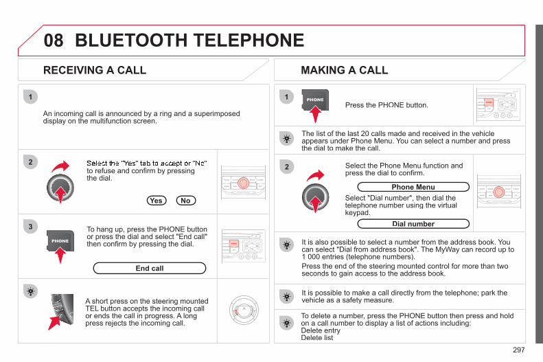
297
08
1
3
2 2
1
to refuse and confi rm by pressing the dial.
RECEIVING A CALL MAKING A CALL
An incoming call is announced by a ring and a superimposed display on the multifunction screen.
Yes
To hang up, press the PHONE buttonor press the dial and select "End call"then confi rm by pressing the dial.
End call
Press the PHONE button.
Select "Dial number", then dial the telephone number using the virtualkeypad.
Select the Phone Menu function and press the dial to confi rm.
The list of the last 20 calls made and received in the vehicle appears under Phone Menu. You can select a number and pressthe dial to make the call.
No
It is also possible to select a number from the address book. Youcan select "Dial from address book". The MyWay can record up to1 000 entries (telephone numbers). Press the end of the steering mounted control for more than twoseconds to gain access to the address book.
Phone Menu
Dial number
It is possible to make a call directly from the telephone; park the vehicle as a safety measure.
BLUETOOTH TELEPHONE
A short press on the steering mountedTEL button accepts the incoming callor ends the call in progress. A longpress rejects the incoming call.
To delete a number, press the PHONE button then press and hold on a call number to display a list of actions including:Delete entryDelete list

298
09
4
3
2
1
6
5
CONFIGURATION
SETTING THE DATE AND TIME The SETUP function gives access to the following options: Systemlanguage, Date & Time, Display (Brightness, Colour, Map colour), Vehicle,Units, System.
Adjust the settings one by one usingthe direction arrows and confi rm bymeans of the dial.
Select the "Date format" function andpress the dial to confi rm.
Select the "Set date & time" function and press the dial to confi rm.
Confi rm the format required using the dial. Pressing the SETUP button for more than 2 seconds gives access to:
These settings must be entered again if the battery has been disconnected.
Press the SETUP button.
Confi rm the format required usingthe dial. Select the "Time format" function and press the dial to confi rm.
Set date & time
Select the "Date & Time" functionand press the dial to confi rm.
Demo mode
GPS coverage
Description of the unit
Date & Time

299
10
RADIO
SCREEN MENU MAP
"Traffic" Menu
Messages on route
Only warnings on route
All warning messages
All messages
Within 2 miles (3 km)
Geo. Filter
Within 3 miles (5 km)
Within 6 miles (10 km)
Within 30 miles (50 km)
Within 60 miles (100 km)
"Music" Menu
Select music
Sound settings
Balance/Fader
Bass/Treble
Linear
Equalizer
Classic
Jazz
Rock/Pop
Techno
Vocal
Loudness
Speed dependent volume
Reset sound settings
"Radio" Menu
Waveband
AM
Linear
FM
Manual tune
Sound settings
Balance/Fader
Bass/Treble
Equalizer
MAIN FUNCTION
OPTION A
option A1
option A2
OPTION B...
1
2
3
1
2
4
1
2
3
4
3
3
3
3
2
2
2
2
4
4
4
4
4
3
3
3
3
3
2
3
2
2
3
3
3
3
1
2
3
2
3

300
Abort guidance/Resume guidance
Destination input
Geo position
Map
Stopovers
Add stopover
Navigate HOME
Choose from address book
Rearrange route
Choose from last destinations
Replace stopover
Delete stopover
Recalculate
Fast route
Short route
Optimized route
POI search
POI nearby
Route options
Route type
Short route
Fast route
"Navigation" Menu
City
Street
Enter new address
Country
Navigate HOME
City district
House number
Start route guidance
Postal code
Save to address book
Intersection
Address input
POI near destination
POI in city
POI in country
POI near route
Choose from address book
3
3
Choose from last destinations
TMC station information
Loudness
Speed dependent volume
Reset sound settings
3
3
3
1
2
4
4
4
4
4
4
4
4
4
4
4
3
2
3
3
2
3
4
4
4
4
3
3
3
3
4
4
4
2
4
2
3
3
3
3
3
3
4
Classic
Jazz
Rock/Pop
Techno
Vocal
4
4
4
4
4

301
Avoid ferries
Recalculate
Settings
Navi volume
POI categories on Map
Set parameters for risk areas
Display on map
Visual alert
Sound alert
3
2
4
3
3
3
4
4
4
Dial from address book
"Phone" Menu
Search phone
Call lists
Connect phone
Select ring tone
Phone/Ring tone volume
Phones connected
Enter mailbox number
Settings
Disconnect phone
Rename phone
Delete pairing
Delete all pairings
Show details
"SETUP" menu
System language *
English
Español
Deutsch
Italiano
Français
Nederlands
Polski
Portuguese
Date & Time *
Set date & time
Date format
Time format
1
2
2
2
2
3
3
4
4
4
4
4
2
3
3
3
1
2
3
3
3
3
3
3
3
3
3
3
3
2
Avoid motorways
Route dynamics
Traffi c independent
Semi-dynamic
Avoidance criteria
Avoid toll roads
Optimized route
3
3
4
4
4
4
4
* Available according to model.

302
** The parameter settings vary according to vehicle.
Dark blue
Map colour
Night mode for map
Units
Day mode for map
Vehicle **
Vehicle information
Alert log
Status of functions
Temperature
Celsius
Fahrenheit
Metric/Imperial
Kilometres (Consumption: l/100)
Kilometres (Consumption: km/l)
Miles (Consumption: MPG)
System
Auto. Day/Night for map
Factory reset
Software version
Automatic scrolling
3
4
4
2
4
3
4
4
2
3
4
4
3
4
4
4
2
4
3
3
3
Colour
Pop titanium
Toffee
Blue steel
Technogrey
3
4
4
4
4
Display
Brightness
2
3

303
FREQUENTLY ASKED QUESTIONSQUESTION ANSWER SOLUTION
There is a difference in sound quality betweenthe different audiosources (radio, CD...).
For optimum sound quality, the audio settings (Volume, Bass, Treble, Ambience, Loudness) can be adapted to the different sound sources,which may result in audible differences when changing source (radio,CD...).
Check that the audio settings (Volume, Bass, Treble, Ambience, Loudness) are adapted tothe sources listened to. It is advisable to setthe AUDIO functions (Bass, Treble, Front-Rear Balance, Left-Right Balance) to the middle position, select the Linear musical ambience andset the loudness correction to the "Active" position in CD mode or to the "Inactive" position in radio mode.
The CD is ejected automatically or is not played by the player.
The CD is inserted upside down, is unplayable, does not contain any audio data or contains an audio format which the player cannot play. The CD is protected by an anti-pirating protection system which is not recognised by the audio equipment.
- Check that the CD is inserted in the player the right way up.
- Check the condition of the CD: the CD cannot be played if it is too damaged.
- Check the content in the case of a recordedCD: consult the advice in the Audio section.
- The audio equipment's CD player does notplay DVDs.
- Because of their quality level, certain writeable CDs will not be played by the audio system.
The CD player sound ispoor.
The CD used is scratched or of poor quality. Insert good quality CDs and store them in suitable conditions.
The audio equipment settings (bass, treble, ambiences) are unsuitable. Set the treble or bass level to 0, without selectingan ambience.

304
QUESTION ANSWER SOLUTION
The stored stations donot function (no sound, 87.5 Mhz is displayed...).
An incorrect waveband is selected. Press the BAND AST button to return to the waveband (AM, FM1, FM2, FMAST) on which thestations are stored.
The quality of receptionof the radio station listened to graduallydeteriorates or the stored stations do not function(no sound, 87.5 Mhz is displayed...).
The vehicle is too far from the transmitter used by the station listenedto or there is no transmitter in the geographical area through which the vehicle is travelling.
Activate the RDS function to enable the system to check whether there is a more powerful transmitter in the geographical area.
The environment (hills, buildings, tunnels, basement car parks...) block reception, including in RDS mode.
This phenomenon is normal and does not indicate a failure of the audio equipment.
The aerial is absent or has been damaged (for example when goingthrough a car wash or into an underground car park).
Have the aerial checked by a CITROËN dealer.
Sound cut-outs of 1 to2 seconds in radio mode.
During this brief sound cut-out, the RDS searches for any frequency permitting better reception of the station.
Deactivate the RDS function if the phenomenon is too frequent and always on the same route.
With the engine off, the audio equipment switches off after a few minutes of use.
When the engine is switched off, the audio equipment operating timedepends on the battery charge. The switch-off is normal: the audio equipment switches to economy mode and switches off to prevent discharging of the vehicle's battery.
Start the vehicle's engine to increase the batterycharge.
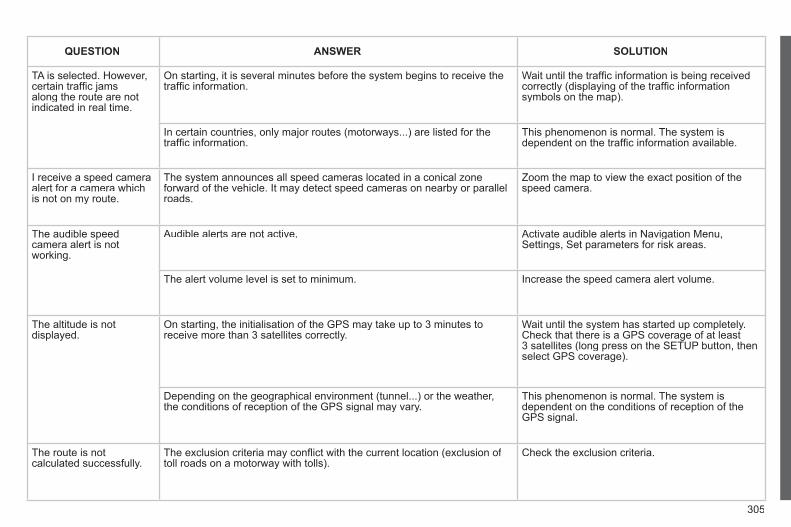
305
QUESTION ANSWER SOLUTION
TA is selected. However, certain traffi c jams along the route are notindicated in real time.
On starting, it is several minutes before the system begins to receive thetraffi c information.
Wait until the traffi c information is being received correctly (displaying of the traffi c information symbols on the map).
In certain countries, only major routes (motorways...) are listed for thetraffi c information.
This phenomenon is normal. The system isdependent on the traffi c information available.
I receive a speed camera alert for a camera whichis not on my route.
The system announces all speed cameras located in a conical zoneforward of the vehicle. It may detect speed cameras on nearby or parallel roads.
Zoom the map to view the exact position of thespeed camera.
The audible speedcamera alert is not working.
Audible alerts are not active. Activate audible alerts in Navigation Menu, Settings, Set parameters for risk areas.
The alert volume level is set to minimum. Increase the speed camera alert volume.
The altitude is not displayed.
On starting, the initialisation of the GPS may take up to 3 minutes toreceive more than 3 satellites correctly.
Wait until the system has started up completely. Check that there is a GPS coverage of at least3 satellites (long press on the SETUP button, then select GPS coverage).
Depending on the geographical environment (tunnel...) or the weather, the conditions of reception of the GPS signal may vary.
This phenomenon is normal. The system isdependent on the conditions of reception of the GPS signal.
The route is notcalculated successfully.
The exclusion criteria may confl ict with the current location (exclusion of toll roads on a motorway with tolls).
Check the exclusion criteria.

306
QUESTION ANSWER SOLUTION
There is a long waiting time after inserting a CD.
When a new medium is inserted, the system reads a certain amount of data (directory, title, artist, etc.). This may take a few seconds.
This phenomenon is normal.
I cannot connect myBluetooth telephone.
The telephone's Bluetooth function may be deactivated or the equipmentmay not be visible.
- Check that your telephone's Bluetoothfunction is activated.
- Check that your telephone is visible.
A telephone connected by Bluetooth is inaudible.
The volume level depends on both the system and the telephone. Increase the MyWay volume setting, possibly to maximum, and increase the telephone volume level if necessary.

307
Audio System
Your Audio system is coded in such a way that it willonly operate in your vehicle.
For safety reasons, the driver must carry out operations which require prolonged attention while the vehicle is stationary. When the engine is switched off and to prevent discharging of the battery, the audio equipment mayswitch off after a few minutes.
AUDIO SYSTEM/BLUETOOTH
01 First steps 02 Steering mounted controls 03 Main menu 04 Audio 05 USB Box 06 Bluetooth functions 07 Configuration 08 Screen menu map Frequently asked questions
p. p. p. p. p. p. p. p. p.
308 309 310 311 314 317 320 322 327
CONTENTS

308
01
11
22
1010 1111
133144155
33 44 55 66 77 8899
122
FIRST STEPS
1. On/Off and volume adjustment. 2. CD eject. 3. Selection of the display on the screen from
the modes:Audio (AUDIO), Trip Computer (TRIP) andTelephone (TEL) functions.
4. Selection of source: radio, audio CD/MP3 CD, USB, auxiliaryconnection, Streaming.
5. Selection of FM1, FM2, FMast and AMwavebands.
6. Setting audio options: front/rear balance, left/right balance, loudness, sound ambience.
7. Display the list of local stations, the tracks onthe CD or the MP3 folders.
8. Abandon current operation. 9. TA (Traffi c Announcement) function on/off. Long press: access to the PTY (Types of radio
programme) mode. 10. Confi rmation. 11. Automatic search for a lower/higher frequency. Selection of previous/next CD, MP3 or USB track.
12. Selection of lower/higher radio frequency. Selection of previous/next CD. Selection of previous/next MP3 folder. Selection of previous/next USB equipment
folder/genre/artist/playlist. 13. Display main menu. 14. Buttons 1 to 6: Selection of a stored radio station. Long press: storing of a station. 15. The MUTE button cuts off or restores the sound.

309
02
32
1 5
4
2
1
32
1 5
4
STEERING MOUNTED CONTROLS
1. Volume increase. 2. Volume decrease. 3. Mute.4. RADIO:
selection of the previous or next storedstation.CD/MP3/USB:selection of the previous or next directory. CD CHANGER: selection of the previous or next CD.
5. RADIO: automatic search for a higher frequency. CD/MP3/CD CHANGER/USB:selection of the next track. CD/MP3/CD CHANGER:continuous press: fast forwards play.
If your vehicle is fi tted with the Bluetooth system: 1. Press: activation of telephone voice
recognition (if the telephone offers thisfunction).
2. Press: displays the phone book, of the call list.
1. Displays the main screen.2. Selection of the type of information displayed
on the right-hand side of the screen for the monochrome screen A.
3. Abandon the operation in progress and return to the previous display.
4. Navigation through the menus. 5. Confi rmation of the function selected.
If your vehicle is fi tted with the Bluetooth system: pick up an incoming call or hang up a call which is in progress.

310
03 MAIN MENU
AUDIO FUNCTIONS :radio, CD, USB, options.
> MONOCHROME SCREEN C
For a detailed global view of themenus available, refer to the "Screen menu map" section.
TELEPHONE:Bluetooth hands-free,pairing, managementof a call.
PERSONALISATION-CONFIGURATION: vehicle parameters, display, languages.
TRIP COMPUTER: entering of distances,alerts, status of functions.
> MONOCHROME SCREEN A

311
04
1
2
3
4
1
2
3
4
SOURCE
BANDAST
LISTREFRESH
MENU
AUDIO
Press the SOURCE button several times in succession and select theradio.
Press the BAND AST button to select a waveband: FM1, FM2, FMast, AM.
Briefl y press one of the buttons tocarry out an automatic search of theradio stations.
Press one of the buttons to carry outa manual search up/down for radiofrequencies.
Press the LIST REFRESH button todisplay the list of stations receivedlocally (30 stations maximum). To update this list, press for morethan two seconds.
The external environment (hills, buildings, tunnels, basement car parks, ...)may block reception, including in RDS mode. This is a normal effect of the way in which radio waves are transmitted and does not indicate any failure of the audio system.
RDS RADIO SELECTING A STATION
Press the MENU button.
Select AUDIO FUNCTIONS thenpress OK.
Select the FM WAVEBAND PREFERENCES function then press OK.
Select ACTIVATE RDS then press OK. RDS appears on the screen.
In radio mode, press OK directly to activate/deactivate RDSmode.
The RDS, if displayed, enables you to continue listening to the samestation by automatic retuning to alternative frequencies. However, in certainconditions, coverage of an RDS station may not be assured throughout thecountry as radio stations do not cover 100 % of the territory. Under conditionsof very weak reception, the system may change to a regional station.

312
04
1
2
3
SOURCE
AUDIO
Insert circular compact discs only.Some anti-pirating systems, on original discs or CDs copied using apersonal recorder, may cause faults which are no refl ection onthe quality of the original player.Without pressing the EJECT button, insert a CD in the player, playbegins automatically.
CD PLAYING A CD
To play a disc which has already beeninserted, press the SOURCE buttonseveral times in succession andselect CD.
Press one of the buttons to select a track on the CD.
Press the LIST REFRESH button to display the list of tracks onthe CD.
Press and hold one of the buttons for fast forward or backward.
RECEIVING TA MESSAGES
Press the TA button to activate or deactivate traffi c messages.
The TA (Traffi c Announcement) function gives priority to TA alert messages. To operate, this function needs good reception of a radio station transmitting this type of message. When a traffi c report is transmitted, the current audio source (Radio, CD, ...) is interrupted automatically to play the TA message. Normal playbackof the audio source resumes at the end of the transmission ofthe message.

313
04
1
2
3
SOURCE
The MP3 format, an abbreviation of MPEG 1.2 & 2.5 Audio Layer 3,is an audio compression standard which permits the recording of several tens of music fi les on a single disc.
In order to be able to play a recorded CDR or CDRW, when recording, the ISO 9660 level 1.2 or Joliet fi le format isrecommended. If the disc is recorded in another format, it may not be playedcorrectly. It is recommended that the same recording format is always used for an individual disc, with as low a speed as possible(4x maximum) for optimum sound quality. In the particular case of a multi-session CD, the Joliet format is recommended.
The audio system will only play fi les with the extension ".mp3" witha sampling rate of 22.05 KHz or 44.1 KHz. No other type of fi le(.wma, .mp4, .m3u...) can be played.
It is advisable to restrict fi le names to 20 characters without usingspecial characters (e.g. " ? ; ù) to avoid any playing or displaying problems.
MP3 CD INFORMATION AND ADVICE
AUDIO
Empty CDs are not recognised and may damage the system.
Insert an MP3 compilation in the player. The audio equipment searches for all of the music tracks, whichmay take anything between a few seconds and several tens of seconds, before play begins.
MP3 CD PLAYING AN MP3 COMPILATION
On a single disc, the CD player can read up to 255 MP3 fi lesspread over 8 folder levels. However, it is advisable to keep to a limit of two levels to reduce the access time before the CD isplayed. While the CD is being played, the folder structure is not followed. All of the fi les are displayed on a single level.
To play a disc which has already been inserted, press the SOURCE button several times in successionand select CD.
Press one of the buttons to select atrack on the CD.
Press the LIST REFRESH button to display the list of directories of the MP3 compilation.
Press and hold one of the buttons for fast forward or backward play.
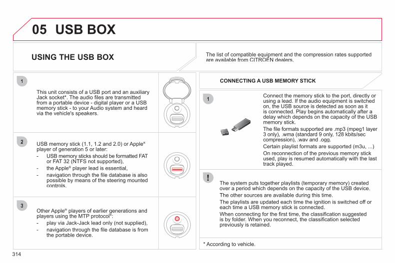
314
05
1
1
2
3
USB BOX
The system puts together playlists (temporary memory) createdover a period which depends on the capacity of the USB device. The other sources are available during this time. The playlists are updated each time the ignition is switched off or each time a USB memory stick is connected. When connecting for the fi rst time, the classifi cation suggestedis by folder. When you reconnect, the classifi cation selected previously is retained.
Connect the memory stick to the port, directly or using a lead. If the audio equipment is switchedon, the USB source is detected as soon as itis connected. Play begins automatically after a delay which depends on the capacity of the USB memory stick. The fi le formats supported are .mp3 (mpeg1 layer 3 only), .wma (standard 9 only, 128 kbits/seccompression), .wav and .ogg. Certain playlist formats are supported (m3u, ...) On reconnection of the previous memory stickused, play is resumed automatically with the lasttrack played.
This unit consists of a USB port and an auxiliaryJack socket * . The audio fi les are transmittedfrom a portable device - digital player or a USBmemory stick - to your Audio system and heardvia the vehicle's speakers.
USB memory stick (1.1, 1.2 and 2.0) or Apple®
player of generation 5 or later: - USB memory sticks should be formatted FAT
or FAT 32 (NTFS not supported), - the Apple ® player lead is essential, - navigation through the fi le database is also
possible by means of the steering mountedcontrols.
The list of compatible equipment and the compression rates supported are available from CITROËN dealers.
p q pp USING THE USB BOX
CONNECTING A USB MEMORY STICK
Other Apple® players of earlier generations and®
players using the MTP protocol * : - play via Jack-Jack lead only (not supplied), - navigation through the fi le database is from
the portable device.
* According to vehicle.

315
3
4
05
2
1
LISTREFRESH
LISTREFRESH
USING THE USB PORT
Press LIST briefl y to display thepreviously selected classifi cation. Navigate through the list using the left/right and up/down buttons. Confi rm the selection by pressing OK.
The lists available are Artist, Genre and Playlist (as defi ned in theApple ® player). Selection and Navigation are described in steps 1 to 4 above.
Do not connect a hard disk or USB connection device other than audio equipment to the USB port. This could damage your installation.
CONNECTING AN APPLE® PLAYER VIA THE USB PORT®
Press one of these buttons to gainaccess to the previous/next track onthe classifi cation list currently beingplayed. Press and hold one of the buttons for fast forward or backward play.
Press one of these buttons to gainaccess to the previous/next Genre, Folder, Artist or Playlist on theclassifi cation list currently being played.
Press and hold LIST to display the different classifi cations. Select by Folder/Artist/Genre/Playlist, press OK to select the classifi cation required, then press OK again to confi rm.
- by Folder: all folders containing audio fi les recognised on the peripheraldevice.
- by Artist: all of the artist names defi ned in the ID3 Tags, classifi ed in alphabetical order.
- by Genre: all of the genres defi ned inthe ID3 Tags.
- by Playlist: in accordance with the playlists recorded on the USB device.
USB BOX

316
05
1
21
2
SOURCE The display and control is via the portable device.
First adjust the volume of your portable device.
Then adjust the volume of your audio system.
USING THE AUXILIARY INPUT (AUX) ADJUSTING THE VOLUME OF THE AUXILIARY SOURCE JACK socket or USB port (according to vehicle)
Connect the portable device (MP3 player…) to the JACK socket or to the USB port, using a suitable cable(not supplied).
Press the SOURCE button severaltimes in succession and select AUX.
The auxiliary input, JACK or USB, allows the connection of a portable device (MP3 player...).
USB BOX
Do not connect a device to both the JACK socket and the USB portat the same time.
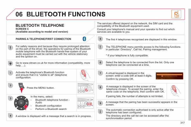
317
06
1
2
3
4
5
6
7
8
9
MENU
OK
For safety reasons and because they require prolonged attentionon the part of the driver, the operations for pairing of the Bluetooth mobile telephone with the Bluetooth hands-free system of your audio equipment must be carried out with the vehicle stationary and the ignition on.
Press the MENU button.
A window is displayed with a message that a search is in progress.
Activate the telephone's Bluetooth functionand ensure that it is "visible to all" (telephone confi guration.
In the menu, select:- Bluetooth telephone function -
Audio - Bluetooth confi guration- Perform a Bluetooth search
The services offered depend on the network, the SIM card and thecompatibility of the Bluetooth equipment used. Consult your telephone's manual and your operator to fi nd out which services are available to you.
BLUETOOTH TELEPHONE SCREEN C
The TELEPHONE menu permits access to the following functionsin particular: Directory * , Call list, Pairing management.
The fi rst 4 telephones recognised are displayed in this window.
A virtual keypad is displayed in thescreen: enter a code with at least 4 digits. Confi rm by pressing OK.
A message that the pairing has been successful appears in thescreen.
Select the telephone to be connected from the list. Only one telephone can be connected at a time.
A message is displayed in the screen of the telephone chosen. To accept the pairing, enter the same code on the telephone, then confi rm with OK.
The automatic connection authorised is only active after thetelephone has been confi gured. The directory and the call list can be accessed after thesynchronisation period.
(Available according to model and version)
* If your telephone is fully compatible.
If pairing fails, the number of attempts is not limited.
Go to www.citroen.co.uk for more information (compatibility, more help, ...).
PAIRING A TELEPHONE/FIRST CONNECTION

318
06
2
1
2
1
OK
RECEIVING A CALL
An incoming call is announced by a ring and a superimposed display in the vehicle's screen.
Select the YES tab on the display using the buttons and confi rm bypressing OK.
Press this button to accept the call.
MAKING A CALL
From the Bluetooth telephone function Audio menu, select Manage the telephone call then Call, Call list or Directory.
Press this button for more than two seconds for access to your directory, then navigate with the thumb wheel. Or To dial a number, use your telephone's keypad,with the vehicle stationary.
During a call, press this button for more than2 seconds. Confi rm with OK to end the call.
BLUETOOTH FUNCTIONS
ENDING A CALL

319
1
2
3
SOURCE
06
Initiate the pairing between the telephone and the vehicle. This pairing can be initiated from the vehicle's telephone function menu or via the telephone's keypad. See steps 1 to 9 on the previous pages. During the pairing phase, the vehicle must be stationary with thekey in the ignition.
Select the telephone to be connected from the telephone functionmenu.The audio system connects to a newly paired telephone automatically.
BLUETOOTH AUDIO STREAMING *
Wireless transmission of the telephone's music fi les via the audioequipment. The telephone must be able to manage the appropriateBluetooth profi les (Profi les A2DP/AVRCP).
* Depending on the compatibility of the telephone.** In certain cases, playing of the Audio fi les must be initiated from the
keypad. *** If the telephone supports the function.
Activate the streaming source by pressing the SOURCE button ** .The tracks to be played can becontrolled as usual via the buttons on the audio system control panel andthe steering mounted controls *** . The contextual information can bedisplayed on the screen.
BLUETOOTH FUNCTIONS

320
07
1
2
3
4
5
6
7
8
MENU
OK
OK
OK
OK
CONFIGURATION
Press the MENU button.
Using the arrows, select DISPLAY CONFIGURATION.
Press to confi rm the selection.
Using the arrows, select YEAR.
Press to confi rm the selection.
Press to confi rm the selection.
Adjust the setting.
Start again from step 1 then set MONTH, DAY, HOUR, MINUTES.
SETTING THE DATE AND TIME SCREEN A
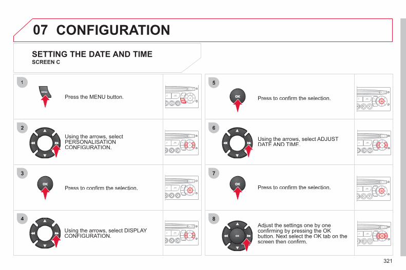
321
07
1
2
3
4
5
6
7
8
MENU
OK
OK
OK
OK
CONFIGURATION
Press the MENU button.
Using the arrows, selectPERSONALISATION CONFIGURATION.
Press to confi rm the selection.
Using the arrows, select DISPLAY CONFIGURATION.
Press to confi rm the selection.
Press to confi rm the selection.
Using the arrows, select ADJUST DATE AND TIME.
Adjust the settings one by one confi rming by pressing the OKbutton. Next select the OK tab on thescreen then confi rm.
SETTING THE DATE AND TIME SCREEN C

322
08 SCREEN MENU MAP RADIO-CD
MAIN FUNCTION
* The parameters vary according to vehicle.
OPTION A
OPTION B...
MONOCHROME A
OPTION A1
OPTION A2
REG MODE
CD REPEAT
RANDOM PLAY
VEHICLE CONFIG *
REV WIPE ACT
OPTIONS
GUIDE LAMPS
DIAGNOSTICS RDS SEARCH
CONSULT
ABANDON
1
2
3
3
1
2
2
2
21
2
3
2
3
1
2
2

323
08 UNITS
FUEL CONSUMPTION: KM/L -L/100 - MPG
1
2
2
SCREEN MENU MAP DISPLAY ADJUST
MONTH
DATE
HOUR
MINUTES
YEAR
12 H/24 H MODE
LANGUAGE
ITALIANO
NEDERLANDS
PORTUGUES
PORTUGUES-BRASIL
FRANCAIS
DEUTSCH
ENGLISH
ESPANOL
1
2
2
2
2
2
2
1
2
2
2
2
2
2
2
2

324
08 SCREEN MENU MAP
Press the OK dial for access to short-cut menus according to the displayon the screen:
MONOCHROME C
activate/deactivate RDS
activate/deactivate REG mode
activate/deactivate radiotext
RADIO
activate/deactivate Intro
CD/MP3 CD
activate/deactivate track repeat (the entire current CD for CD, the entire current folder for MP3 CD)
activate/deactivate random play (the entire current CD for CD, the entire current folder for MP3 CD)
activate/deactivate track repeat (of the current folder/artist/genre/playlist)
USB
activate/deactivate random play (of thecurrent folder/artist/genre/playlist)
1
1
1
1
1
1
1
1
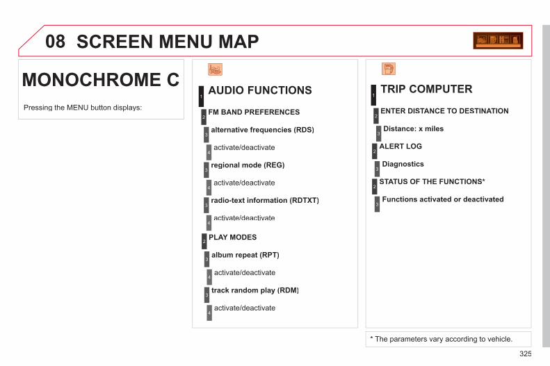
325
08
MONOCHROME C
SCREEN MENU MAP
AUDIO FUNCTIONS
alternative frequencies (RDS)
activate/deactivate
FM BAND PREFERENCES
regional mode (REG)
activate/deactivate
radio-text information (RDTXT)
activate/deactivate
1
2
3
4
3
4
3
4
PLAY MODES
album repeat (RPT)
activate/deactivate
track random play (RDM)
activate/deactivate
2
3
4
3
4
TRIP COMPUTER
Distance: x miles
ENTER DISTANCE TO DESTINATION
Diagnostic s
ALERT LOG
Functions activated or deactivated
STATUS OF THE FUNCTIONS *
1
2
3
3
2
3
2
Pressing the MENU button displays:
* The parameters vary according to vehicle.
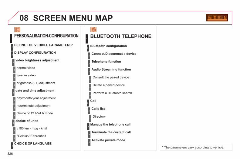
326
08 SCREEN MENU MAP
BLUETOOTH TELEPHONE
Connect/Disconnect a device
Consult the paired device
Bluetooth confi guration
Telephone function
Audio Streaming function
Delete a paired device
Perform a Bluetooth search
Calls list
Call
Directory
Terminate the current call
Manage the telephone call
Activate private mode
1
2
3
3
3
4
4
4
2
3
4
2
3
3
video brightness adjustment
DISPLAY CONFIGURATION
DEFINE THE VEHICLE PARAMETERS *
PERSONALISATION-CONFIGURATION
normal video
inverse video
brightness (- +) adjustment
date and time adjustment
day/month/year adjustment
hour/minute adjustment
choice of 12 h/24 h mode
choice of units
l/100 km - mpg - km/l
°Celsius/°Fahrenheit
CHOICE OF LANGUAGE
1
2
4
3
2
4
4
3
4
4
2
3
4
4
4
* The parameters vary according to vehicle.

327
FREQUENTLY ASKED QUESTIONSQUESTION ANSWER SOLUTION
There is a difference in sound quality betweenthe different audiosources (radio, CD...).
For optimum sound quality, the audio settings (Volume, Bass, Treble, Ambience, Loudness) can be adapted to the different sound sources,which may result in audible differences when changing source(radio, CD...).
Check that the audio settings (Volume, Bass, Treble, Ambience, Loudness) are adapted tothe sources listened to. It is advisable to setthe AUDIO functions (Bass, Treble, Front-Rear Balance, Left-Right Balance) to the middle position, select the musical ambience "None" and set the loudness correction to the "Active" position in CD mode or to the "Inactive" position in radio mode.
The CD is ejected automatically or is not played by the player.
The CD is inserted upside down, is unplayable, does not contain any audio data or contains an audio format which the player cannot play. The CD is protected by an anti-pirating protection system which is not recognised by the audio equipment.
- Check that the CD is inserted in the playerthe right way up.
- Check the condition of the CD: the CD cannot be played if it is too damaged.
- Check the content in the case of a recordedCD: consult the advice in the "Audio" section.
- The audio equipment's CD player does notplay DVDs.
- Due to their quality level, certain writeableCDs will not be played by the audio system.
The message "USB peripheral error" isdisplayed on the screen. The Bluetooth connectionis cut.
The battery of the peripheral may not be suffi ciently charged. Recharge the battery of the peripheral device.
The USB memory stick is not recognised. The memory stick may be corrupt.
Reformat the memory stick.
The CD player sound ispoor.
The CD used is scratched or of poor quality. Insert good quality CDs and store them in suitable conditions.
The audio equipment settings (bass, treble, ambiences) are unsuitable. Set the treble or bass level to 0, without selectingan ambience.

328
QUESTION ANSWER SOLUTION
The stored stations donot function (no sound, 87.5 Mhz is displayed...).
An incorrect waveband is selected. Press the BAND AST button to return to the waveband (AM, FM1, FM2, FMAST) on whichthe stations are stored.
The traffi c announcement(TA) is displayed. I donot receive any traffi c information.
The radio station is not part of the regional traffi c information network. Tune to a radio station which broadcasts traffi c information.
The quality of receptionof the radio station listened to graduallydeteriorates or the stored stations do not function(no sound, 87.5 Mhz is displayed...).
The vehicle is too far from the transmitter used by the station listened to or there is no transmitter in the geographical area through whichthe vehicle is travelling.
Activate the RDS function to enable the system to check whether there is a more powerful transmitter in the geographical area.
The environment (hills, buildings, tunnels, basement car parks...) block reception, including in RDS mode.
This phenomenon is normal and does not indicate a failure of the audio equipment.
The aerial is absent or has been damaged (for example when goingthrough a car wash or into an underground car park).
Have the aerial checked by a CITROËN dealer.
Sound cut-outs of 1 to2 seconds in radio mode.
During this brief sound cut-out, the RDS searches for any frequency permitting better reception of the station.
Deactivate the RDS function if the phenomenon is too frequent and always on the same route.
With the engine off, the audio equipment switches off after a few minutes of use.
When the engine is switched off, the audio equipment operating timedepends on the battery charge. The switch-off is normal: the audio equipment switches to economy mode and switches off to prevent discharging of the vehicle's battery.
Start the vehicle's engine to increase the batterycharge.
The message "the audio system is overheated" appears on the display.
In order to protect the installation if the surrounding temperature is toohigh, the audio equipment switches to an automatic thermal protectionmode leading to a reduction of the volume or stopping of the playing of the CD.
Switch the audio system off for a few minutes toallow the system to cool.

329
For reasons of safety, the driver should only carry outoperations which require prolonged attention while thevehicle is stationary.The player is compatible with the following formats:DVD-R, DVD+R, DVD+RW, CD-R, CD-RW, VCD and SVCD.Using the AUX1 and AUX2 inputs, this pack permitsthe connection of auxiliary systems (camcorder, games console, etc.). The audio equipment only plays audio fi les with the extension ".mp3" with a sampling rate of 32 KHz to48 KHz.
All of the functions of the video pack are described in theseparate manual supplied with your vehicle.
VIDEO PACK DVD/AUDIO CD/MP3 PLAYER
01 First steps
02 Configuration
03 Basic functions
04 Screen menu map
Frequently asked questions
p.
p.
p.
p.
p.
CONTENTS 330
332
333
335
336

330
01
12
896
3
3
4
1
7
5 2
FIRST STEPS
MONITORS AND DVD/CD PLAYER INFRA-RED HEADPHONES
The monitors are located inthe tops of the front seats.
The DVD/CD player is located on the centre console.
1. Monitor positioning handles. 2. Folding and pivoting TFT/LCD screen.3. Infra-red cell.4. DVD/CD player opening provided for the
disc.5. On/Off.
DVD/CD eject.
6. LED: On green: player in operation. Flashing: receiving information or ejecting
the disc. 7. AV1 AUDIO input. 8. AV2 AUDIO input. 9. VIDEO input.
1. 2 channel stereo. 2. On/Off. 3. Volume adjustment.
The headphones are supplied with the video pack. The presence of an object between the infra-red cell on the monitor and the headphones may result in a reduction in the sound quality.
Supply: 2 batteries R03/AAA 1.5 V.

331
9977
88
1111 1010122
133
144
155 55
44166
22
11188
177 33
66
01 FIRST STEPS
REMOTE CONTROL
1. Power On/Off, Eject. 2. Selection of the source from
DVD, audio CD and AUX.3. Change screen. 4. DVD screen adjustments
(brightness, contrast, …).5. Selection confi rmation.6. Fast forward/backward.
In the menus: move the cursor left/right, up/down.
7. Volume increase/decrease. 8. Play/Pause. 9. Next chapter. 10. SHIFT: activation of the yellow
buttons.11. Selection of the audio
language.With SHIFT: selection of thesubtitle language.
12. Change chapter. With SHIFT: change title.
13. Previous chapter.14. Stop play. 15. RETURN:
Short press: return tothe previous menu.Long press: return to the main menu.
16. Display the main DVD menu.17. ZOOM: Selection of different
image formats. 18. Display/mask the screen.Power: 2 batteries R03/AAA 1.5 V.
Numeric keypad

332
02
1
2
3
5
4
1
2
3
CONFIGURATION
SETUP MENU
The "Settings" menu appears on the screen: "Video settings", "Languages", "Users", "Defaultsettings". Select the options using the and buttons.
Press the SETUP button.
Press the OK button to confi rm your choice.
The "Video settings" menu appears on the screen:"Brightness", "Contrast", "Colour", "Back-lighting".
Select the "Video settings" menu using the and buttons.
Press the SETUP button. The "Settings" menuappears on the screen.
Press the OK button to confi rm your choice. The setting is saved.
Select the input required using the and buttons.
VIDEO SETTINGS

333
03
31
2
BASIC FUNCTIONS
SETTING UP THE MONITORS
Using the positioning handles,extract the monitor from the casing.
Release the table using the button and tilt it down.
The monitor is not a touch screen.Do not press directly on the surface of the monitor, this may damage the LCD screen.
Pivot the monitor upwards until it is in contact with the upper part of theseat. A notch locks it in position.

334
1
2
3
4
1
2
BASIC FUNCTIONS
VIDEO PACK ON/OFF
Press the POWER/EJECT button on the DVD/CDplayer or on the remote control.
To switch on the system, switch on the vehicle's ignition.
When the ignition is off, the video pack will switch off automatically after approximately ten minutes to avoid discharging the battery.
Play begins automatically.
To load a disc, insert it carefully, printed face uppermost, until it is fully inserted.
Remove the disc carefully.
Press the POWER/EJECT button on the DVD/CD player or remote control.
LOADING/EJECTING A DVD/CD

335
04 SCREEN MENU MAP SETTINGS 1 LANGUAGES
SUBTITLES
AUDIO
1
2
SETTINGS
DEFAULT SETTINGS
YES
ARE YOU SURE?
1
2
3
NO 3
2
2
USERS
USER 2
USER 1
1
2
USER 3
2
2
VIDEO SETTINGS
CONTRAST
BRIGHTNESS
1
2
COLOUR
BACK-LIGHTING
2
2
2

336
FREQUENTLY ASKED QUESTIONS The table below groups together the answers to the most frequently asked questions concerning the video pack.
QUESTION SOLUTION
The player does not start. - Check the vehicle's fuses.
The player does not react to pressing of theremote control buttons.
- The remote control batteries are fl at. Replace them. - The remote control sensor is hampered by objects or is dirty. Remove all objects on the remote control
receiver or clean the surface using a damp cloth. - The video pack has overheated. Let it cool for a few minutes.
Image or sound interference while playinga DVD. The image remains frozen during play.
The player cannot read the disc. The disc may be damaged or dirty.
The player does not play the disc inserted. - The format of the disc does not correspond to the specifi cations of the player. - If it is cold, condensation may have formed on the laser. Wait approximately 5 minutes to allow
the humidity to evaporate.
When a DVD/VCD/SVCD is played,the image is of poor quality.
- Remove the disc. - Using the SETUP button, adjust the brightness and insert the disc again.
No image is displayed on the monitor. - Press the SOURCE button until the image appears. - Press the SCREEN ON/OFF button.
There is no sound in the audio headphones. - Increase the volume using the VOLUME +/- buttons on the remote control or using the dial onthe headphones.
- Check that the correct channel is selected on the headphones. - Press the SOURCE button until the sound arrives. - Replace the headphone batteries.
The start-up screen does not appear following ejection of the disc.
- Insert another disc. - Switch the system off and then on again.

337
V I S U A L S E A R C H
EXTERIOR
Remote control key....................... 78-83 - opening/closing - anti-theft protection - guide-me-home lighting - starting - battery Very cold climate screen.................. 210
Exterior lighting controls ...................................... 94-97
Headlamp adjustment........................ 98 Directional lighting ............................. 99 Wipers ............................................. 100 Changing bulbs......................... 190-193 - front lamps - front foglamps - side repeaters Lane departure
warning system............................. 168
Door mirrors ....................................... 76 Side spotlamps .................................. 98
Doors ............................................ 88-89 - opening/closing - central locking - emergency control Child lock ......................................... 125 Electric windows ........................... 86-87
Under-infl ation detection.................. 127 Braking assistance .......................... 128 Trajectory control ............................. 129 Pneumatic suspension ............. 171-172 Tyre pressures ................................. 226
Accessories .............................. 211-212 Panoramic sunroof ............................ 91 Roof bars ......................................... 210
Fuel tank ............................................ 92
Boot ................................................... 90 Temporary puncture
repair kit ................................. 183-185 Changing a wheel ..................... 186-189 - tools - removing Opening rear screen .......................... 90
Parking sensors ........................ 169-170 Towbar ............................................. 209 Towing ............................................. 207
Changing bulbs......................... 194-196 - rear lamps - 3rd brake lamp - number plate lamp

338
V I S U A L S E A R C H
Dashboard fuses ...................... 197-199
Opening the bonnet ......................... 174 Changing a fuse .............................. 197
5-speed manual gearbox ................. 147 Electronic gearbox
system ................................... 149-152 Automatic
gearbox.................................. 156-159 Hill start assist ................................. 146
Sun visor.......................................... 105
Electric parking brake...................................... 139-145
Courtesy lamps................................ 103 Toll/parking ticket windows .............. 105 Child surveillance mirror .................. 105 Rear view mirror ................................ 77
Interior fi ttings ........................... 106-108 - glovebox - storage - cool storage - mat
INSTRUMENTS AND CONTROLS
NaviDrive .................................. 231-273 Setting the date/time........................ 264 MyWay ...................................... 275-306 Setting the date/time........................ 298 Audio system ............................ 307-328 Setting the date/time........................ 320
General: ventilation/heating/air conditioning ............................... 56-57
Manual air conditioning................. 58-59 Digital air conditioning .................. 60-63 Additional air conditioning.................. 64
Centre console ................................ 107 Smoker's kit ..................................... 107 Emergency or
assistance call ...................... 130, 227 Lane departure
warning system............................. 168

339
V I S U A L S E A R C H
Exterior lighting controls ...................................... 94-97
Direction indicators .......................... 126
Steering mounted controls........ 160-161 Speed limiter............................. 162-163 Cruise control ........................... 164-165 Parking space sensor ............... 166-167
Alarm ................................................. 84 Headlamp adjustment........................ 98 Stop & Start ..................................... 153 Opening the fuel fi ller fl ap .................. 92 Parking sensors ........................ 169-170
Instrument panels ......................... 31-32 Warning lamps .............................. 33-41 Indicators ...................................... 42-43 Gear shift
indicator ........................................ 148 Mileage recorders .............................. 44 Lighting dimmer ................................. 44
Door mirrors ....................................... 76 Electric windows, deactivating ...... 86-87
Horn ................................................. 126 Steering wheel adjustment ................ 77
Hazard warning lamps ..................... 126 Scented air freshener ................... 65-66
Wiper controls........................... 100-102 Trip computer ............................... 53-55
Interior mood lighting ....................... 104
Multifunction screens .................... 45-53 - Screen A - Screen C - MyWay colour screen - NaviDrive colour screen
INSTRUMENTS AND CONTROLS (CONTINUED)

340
V I S U A L S E A R C H
Boot fi ttings ................................111-115 - rear parcel shelf - modubox (C4 Picasso) - net and luggage cover
(Grand C4 Picasso) - bag hook - separation net
(Grand C4 Picasso) - lashing rings - luggage net
(Grand C4 Picasso) Torch .................................................116
Rear seats (3rd row) .......................... 74 Seat modularity/
confi guration ................................... 75
Conventional child seats........... 117-121 ISOFIX child seats .................... 122-124 Child lock ......................................... 125
Side blinds ........................................110
Rear head restraints .......................... 70 Rear seats (2nd row) .................... 70-73
Rear fi ttings .............................. 109-110 - rear tables - footwell storage - side blinds - rear blind (Grand C4 Picasso)
Seat belts.................................. 131-134
Mats ................................................. 108
Airbags ..................................... 135-138 Deactivating the passenger's
front airbag ................................... 136
Video pack ................................ 329-336
Front seats.................................... 67-69 - manual - electric
INTERIOR

341
V I S U A L S E A R C H
Checking levels ........................ 179-180 - oil - brake fl uid - power steering fl uid - coolant - screenwash/headlamp wash fl uid
Changing bulbs ...................................... 190-193
Petrol engines.................................. 213 Petrol weights .................................. 214 Diesel engines .......................... 215-216 Diesel weights .......................... 217-220 Petrol/Diesel weights,
commercial versions .............. 221-222 Dimensions ............................... 223-225 Identifi cation markings ..................... 226 Bleeding the Diesel fuel fi lter ........... 175
Running out of fuel, Diesel .............. 176
Opening the bonnet ......................... 174 Under the bonnet, petrol .................. 177 Under the bonnet, Diesel ................. 178
Checking components .............. 181-182 - battery - air/passenger compartment fi lter - oil fi lter - particle fi lter (Diesel) - brake pads/discs
Fuses at the battery ......................... 202 Battery ...................................... 203-205 Energy economy mode.................... 206
Engine compartment fuses ...................................... 200-201
TECHNICAL DATA - MAINTENANCE

342
A L P H A B E T I C A L I N D E X
ABS and EBFD systems........128Accessories ........................... 211Accessory socket, 12 V .........107Access to the 3rd row ..............72Adjusting headlamps ...............98Adjusting head restraints ...67, 70Adjusting seat belt height.......131Adjusting the steering wheel ....77Airbags, curtain..............137, 138Airbags, front .........................138Airbags, lateral ...............137, 138Air conditioning ..................29, 56Air conditioning, additional.......60Air conditioning, digital .............60Air conditioning, manual ..........58Air distribution adjustment ...t 58, 60Air filter...................................r 181Air flow .....................................29Air flow adjustment ..................60Air recirculation ..................58, 60Air vents...................................56Alarm .......................................84Anti-lock braking system
(ABS)...................................128Anti-pinch...........................86, 91Anti-theft ..................................80Armrest, front ...........................67Ashtray, portable....................107Assistance call ...............130, 228Athermic windscreen .............105Audible warning .....................126Audio streaming
(Bluetooth) ...........................319Audio
system .........307, 309, 322, 324Automatic illumination
of headlamps ...................94, 97
Automatic operation of hazard warning lamps .....................126
Automatic rain sensitivewindscreen wipers.......100, 101
Auxiliary sockets ...........258, 259,294, 314, 316
Centre console .......................107Changing a bulb.....190, 194, 195Changing a fuse.....................197Changing a wheel ..................186Changing a wiper blade .........102Changing
the date................264, 298, 321Changing the remote
control battery........................82Changing
the time ................264, 298, 321Checking levels..............179, 180Checking the engine
oil level...................................43Checks...........177, 178, 181, 182Child lock ...............................125Children .................120, 123, 124Child seats .................... 117, 119Child seats, conventional .......120Child surveillance mirror ........r 105Cigar lighter ...........................r 107CITROËN call button .............229CITROËN services ................229Closing the boot .................79, 90Closing the doors...............79, 88Cold climate screen ...............210Cold storage .........................107Concertina boards ...................74Connectors, audio.........108, 253,
254, 294, 314, 316Control panel .........................276Coolant level ..........................180Courtesy lamps..............103, 196Cruise control.........................164Cup holder .............................r 107
A A C
B Backup starting ......................203Bag hook ................................ 112Battery ...........................181, 203Battery, charging ....................203Battery, remote control .......82, 83Battery compartment
fuse box ...............................197Blind for panoramic sunroof.....f 91Blinds ............................. 105, 110Bluetooth
(hands-free) .........295, 296, 317Bluetooth
(telephone) ..........261, 295, 296Bonnet ...................................174Bonnet stay ............................174Boot .........................................90Boot lamp....................... 116, 196Brake discs ............................182Brake lamps ...................194, 195Brake pads.............................182Brakes....................................182Braking assistance system ....128
Capacity, fuel tank ...................92Cargo net .............................. 114CD MP3 .................252, 293, 313Central locking .............79, 88, 89
C

343
A L P H A B E T I C A L I N D E X
Halogen headlamps...............190Hands-free kit ........295, 296, 317Hard disk (copy).............254, 255Hazard warning lamps...........126Headlamp adjustment..............98Headlamps, directional ......98, 99Headlamp wash.....................101Headlamp wash reservoir ......r 180Head restraints, front ...............67Head restraints, rear ................r 70Heated seats............................68Heating ..............................29, 56Height and reach adjustment,
steering wheel .......................77Hill start assist........................146
Date (setting)........264, 298, 320, 321
Daytime runninglamps.....................96, 190, 193
Deactivating the passenger airbag...................................135
Deadlocking .............................79Demisting
the rear screen ................58, 60Diesel additive level ...............180Dimensions ............................223Dipped beam ...........94, 190, 191Dipstick ............................43, 179Directional lighting ...................99Direction indicators .......126, 190,
192, 194, 195Doors .......................................88Doors emergency control.........89Door trays ......................104, 108Driving positions
(memorising) ..........................69DVD player ............................r 330Dynamic emergency
braking.................................139
Electronic engine immobiliser ......................r 80, 83
Emergency boot release ..........91Emergency braking system ....128Emergency call ......130, 228, 229Emergency warning lamps ....126Energy economy mode..........206Engine, Diesel ..................93, 178Engine, petrol ...................93, 177Engine compartment ......177, 178Engine compartment
fusebox................................197Engine oil level
indicator .........................r 43, 179Engines..........................213, 215Environment .......................29, 83ESP/ASR ...............................129
G.P.S......239, 242, 245, 247, 281Gearbox, automatic .......156, 182Gearbox,
electronic .............149, 153, 182Gearbox,
manual.........147, 148, 153, 182Gear efficiency indicator ........r 148Gear lever ................................r 29Gear lever,
automatic gearbox...............156Gear lever, electronic
gearbox system ...................149Gear lever, manual gearbox ....x 147Glove box ...............................106Guidance ...............239, 245, 281
D E G
H
EBA (Emergency brakingassistance) ..........................128
Eco-driving ..............................29Eco-driving (advice) .................29Economical driving ..................29Economy mode ......................206Electric window controls ..........86Electronic brake force
distribution (EBFD) ..............128
E
Filling with fuel ...................92, 93Fitting a wheel........................188Fitting roof bars ......................210Flashing indicators.................126Foglamps, rear.........................r 95Folding the rear seats.....70, 72, 74Fragrance cartridge .................65Front foglamps.................95, 193Front seats ..........................67-69Fuel....................................29, 93Fuel consumption ....................29Fuel filler cap ...........................92Fuel filler flap ...........................92Fuel gauge...............................92Fuel tank ..................................92Fusebox, dashboard ..............197Fuses .....................................197
F
Identification plates ................226Indicator lamps, status.............39Indicators, direction................126
I

344
A L P H A B E T I C A L I N D E X
Keeping children safe ...............117, 120, 122-124
Key in ignition warning .............81Key with remote
control.........................78-80, 83
Labels, identification ..............226Lamps, rear....................r 194, 195Lamps, warning
and indicator ..............r 33, 36, 37Lane Departure Warning System
(LDWS)................................168LED daytime running lamps.....96Level, brake fluid....................179Level, headlamp wash...........180Level, power steering fluid .....179Levels and checks ..........177-180Lighting, guide-me home.....96, 97
Jack .......................................186JACK socket ..................314, 316Jukebox (playing) ...................256
Inflating tyres ...........................29Inputs for audio
system .........258, 294, 314, 316Instrument panel lighting ..........44Instrument panels ..............31, 32Instrument panel
screen......................31, 32, 148Interior mood lighting .............104ISOFIX child seats ..........122-124ISOFIX mountings .................122
Lighting, interior .............r 103, 196Lighting bulbs
(replacement) ......190, 194, 195Lighting control stalk ................94Lighting dimmer ...........r 31, 32, 44Lighting on reminder ................r 95Lighting pack ..........................104Loading ....................................29Loading/unloading
assistance............................171Load space cover ..................r 111Localised assistance
call ...............................228, 229Localised
emergency call ............228, 229Locating your vehicle ...............80Locking from the inside............88Luggage retaining net ............ 115
Multifunction screen..................45, 47, 50, 52
Music media players ..............292MyWay .............50, 276, 278, 299
I L M
J
K
L
Main beam...............94, 190, 191Maintenance ............................29Map (colour screen)...............247Map reading lamps ........103, 196Markings, identification ..........226Mat .........................................108Menu, main ............236, 237, 310Mini fuel level ...........................92Mirror, rear view.......................77Mirrors, door ............................r 76Modubox ................................ 112Modularity, seats ......................75Motorway function (direction
indicators) ............................126Mountings for ISOFIX seats ....122MP3 CD .................252, 293, 313
M
Navigation......................239, 281Net ......................................... 112Number plate lamps...............195
N
Oil filter...................................r 181Oil level ............................43, 179Opening the bonnet ...............174Opening the boot ...............78, 90Opening the doors .............78, 88Opening the panoramic
sunroof blind ..........................91Opening the rear screen..........90Operation indicator
lamps...................33, 36, 38, 39
O
Paint colour code...................226Panoramic glass sunroof .........f 91Parcel shelf, rear....................r 109Parking brake.........................182Parking brake, electric ...........139Parking sensors, front............170Parking sensors, rear.............r 169Parking space sensor ...........166Particle emission filter....r 180, 181Passenger compartment
filter......................................r 181Player, CD MP3 .....252, 293, 313Pneumatic suspension...........171
P

345
A L P H A B E T I C A L I N D E X
Port,USB .....108, 253, 254, 314, 316
Priming the fuel system .........175Protecting
children.........117, 120, 122-124Puncture ........................183, 186
Reversing lamp ..............194, 195Rigid panel ...............................72Risk areas (update) .......244, 288Roof bars ...............................210Routine checks ..............181, 182Running out of fuel (Diesel) ....175
Short-cut menus ............279, 280Sidelamps...94, 96, 190, 192-195Side repeater .........................r 192Spare wheel ...........................186Speed limiter..........................r 162Speedometer .....................r 31, 32Spotlamps, side .......................98Stability control (ESP)............129Starting the vehicle ..................81Steering lock ............................81Steering mounted
controls ................233, 277, 309Steering wheel,
fixed centred controls ..........160Stopping the vehicle ................81Stop & Start ......................55, 63,
92, 153, 174, 181, 203Storage ..................................109Storage compartments ..........106Storing driving positions ...........69Sun visor................................r 105Sun visor flap .........................105Synchronising
the remote control..................82Synthesiser, voice ..................242System, navigation ................281Systems, ASR and ESP.........129
P R S
Radio ............................. 291, 311Reading lamps, rear ......r 104, 109Rear foglamp .........................193Rear screen, opening ..............90Recharging the battery ..........203Regeneration of the particle
emissions filter.....................r 181Reinitialising the electric
windows.................................86Reinitialising
the remote control..................82Remote control ....78, 79, 83, 331Removable screen
(snow shield) .......................210Removing a wheel .................188Removing the mat ..................108Repair kit, puncture ................183Replacing bulbs .....190, 194, 195Replacing fuses .....................197Replacing the air filter ............r 181Replacing the oil filter ............r 181Replacing the passenger
compartment filter................r 181Replacing wiper blades ..........102Resetting
the service indicator...............43Resetting the trip recorder .......r 44Rev counter .......................r 31, 32
R Safety for children............86, 125Scented air freshener ..............r 65Screen, colour 16/9...........50, 52,
236, 265, 278, 299Screen,
monochrome........310, 322, 324Screen, monochrome A ...........A 45Screen, monochrome C ...........47Screen,
multifunction ........45, 47, 50, 52Screen, rear video .........333, 334Screen-wash reservoir...........r 180Screen menu
map......265, 299, 322, 324, 335Screenwash, front..................101Screenwash fluid level ...........180Seat adjustment ...........67, 68, 70Seat belts.......................131, 134Seat configurations ..................75Seats, rear ...................r 70, 72, 74Security bolts .........................188Serial number, vehicle ...........226Service indicator ................r 42, 43Servicing ......................29, 42, 43Settings (Menus) ....................332Setting
the clock ......264, 298, 320, 321Shelf.........................................f 70
S
Table of weights .....213, 215, 221Tables of engines...........213, 215Tables of fuses.......................197Technical
data..............213, 215, 221, 223Telephone ..............229, 260-262,
295, 296
T

346
A L P H A B E T I C A L I N D E X
Warning lamps ....................37-39Wash-wipe, rear.....................r 100Weights..................213, 215, 221Welcome lighting ...................104Wheel, changing ....................186Window controls ......................86Windscreen zones for toll/car
park cards ............................105Wiper, rear .............................r 100Wiper control stalk .........100, 101Wipers............................100, 101
Under-inflation(detection)............................127
Unlocking .................................78Unlocking from
the inside .........................88, 89Update risk areas...........244, 288Updating the date ..........320, 321Updating the time...........320, 321USB Box ................................108USB Reader...................r 253, 314
Xenon headlamps ..................190
Temperature adjustment ....58, 60Temperature control
for heated seats.....................68Temporary tyre repair kit ........183Third brake lamp....................196TMC (Traffic info) ...........249, 289Toll/car park cards ..................105Tools ......................................186Torch .............................. 116, 196Total distance recorder ............r 44Towbar ...................................r 209Towing another vehicle ..........207Traction control (ASR) ...........129Traffic information
(TA) ......................290, 291, 312Traffic information
(TMC) ..................249, 289, 290Trip computer......................r 53-55Trip distance recorder..............r 44Tyre pressures .......................226Tyres ........................................29Tyre under-inflation
detection ..............................127
Vehicle identification ..............226Ventilation ................................56Video......................................259Video menu ............................259Video pack .............................329
T V
X
U
W

347

348

07-11
This handbook describes all of the equipment available in the whole range. Your vehicle will be fi tted with some of this equipment described in this document, depending on its trim level, version and the specifi cation for the country in which it is sold. The descriptions and illustrations are given without any obligation. Automobiles CITROËN reserves the right to modify the technical specifi cations, equipment and accessories without having to update this edition of the handbook. This document is an integral part of your vehicle. It should be passed on to the new user in the event of sale or transfer.
Automobiles CITROËN declares, by application of the provisions of the European regulation (Directive 2000/53) relating to End of Life Vehicles, that it achieves the objectives set by this regulation and that recycled materials are used in the manufacture of the products that it sells. Reproduction or translation of all or part of this handbook is prohibited without written authorisation from Automobiles CITROËN.
Printed in the EU Anglais
For any work on your vehicle, use a qualifi ed workshop that has the technical information, competence and equipment required, which a CITROËN dealer is able to provide.

CRÉATIVE TECHNOLOGIE
2011 – DOCUMENTATION DE BORD4DconceptDiadeisSeenkEdipro
11C4P.0040Anglais