your portal to - welcome to broward county! “your portal to paradise" and other ......
TRANSCRIPT

Broward County Aviation Department 0
TERMINAL DESIGN
GUIDELINES MANUAL
Revision 1 2017
Leigh|Fisher
in conjunction with
your portal to paradise

Terminal Design Guidelines July 2017 Page 1 of 60
Fort Lauderdale-Hollywood International Airport Leigh|Fisher & ACAI Associates Inc. / Revision 1
BROWARD COUNTY AVIATION DEPARTMENT TERMINAL DESIGN GUIDELINES MANUAL
TABLE OF CONTENTS
CHAPTER TITLE PAGE
Chapter 1 Introduction
1.1 Introduction to Terminal Design Guidelines Manual 2-4 1.2 General Conditions 5-8 1.3 Design Intent Integration 9
Chapter 2 Design Guidelines
2.1 Innovations for Airport Terminals 10-11 2.2 Building Envelope Facades & Roof 12-15 2.3 Materials and Finishes 16-26 2.4 Furnishings, Fixtures and Equipment 27-39 2.5 Signage, Wayfinding and Advertising 40-41 2.6 Lighting 42-45 2.7 Public Art & Design 46 2.8 Sustainability 47-48
Chapter 3 Appendices
3.1 49 3.2 49-50 3.3 51 3.4 51 3.5 51 3.6 51-54 3.7
Guideline Revisions Definitions and Abbreviations Broward County Aviation Department Contacts CADD and BIM Standards Design Guidelines Interpretations Review Process, Submittal Requirements and Approvals Outline Specifications and Airport Systems InformationTerminal Maps
54-60
60 3.8

Terminal Design Guidelines July 2017 Page 2 of 60
Fort Lauderdale-Hollywood International Airport Leigh|Fisher & ACAI Associates Inc. / Revision 1
CHAPTER 1 Introduction
1.1 Introduction to Terminal Design Guidelines Manual The 21st century airport terminal is a passenger service and technology hub that is in constant motion. Within the terminal various activities and convenience services are provided to travelers who have increasing needs for less stressful and more satisfying traveling experiences. Terminal spaces must be designed to function more efficiently and serve travelers more effectively. This requires the airport terminals to be optimized in their design and performance as well as integrated as seamlessly as possible with the processes that are carried out in the day to day functions of the Terminal.
Figure 2: San Diego International Airport Terminal
Figure 1: Norman Y. Mineta San Jose International Airport

Terminal Design Guidelines July 2017 Page 3 of 60
Fort Lauderdale-Hollywood International Airport Leigh|Fisher & ACAI Associates Inc. / Revision 1
The Fort Lauderdale-Hollywood International Airport (FLL) consists of four Terminals and eight concourses
(see figure 3). Each concourse has two floors. The first floor is for arrivals and the second floor is for
departures. Terminals one, two and three are for domestic arrivals and departures. Some concourses at
Terminals one and four are for domestic and international arrivals and departures.
To help ensure a consistent design approach for the integration of each Terminal project into the Fort Lauderdale-Hollywood International Airport this Terminal Design Guidelines Manual or “Terminal DGM” has been developed. The document’s intent is to help bring each Design Professional’s ideas into the fabric of the airport which in and of itself represents its own unique regional features and local culture through the adopted Conceptual Design Statement of “your Portal to Paradise" and other airport branding efforts. It is a resource that helps to clearly outline the Terminal design parameters. It
Figure 3: Terminals and Concourses Key Plan of Fort Lauderdale-Hollywood International Airport
Figure 4: Example of an International Airport Terminal at FLL

Terminal Design Guidelines July 2017 Page 4 of 60
Fort Lauderdale-Hollywood International Airport Leigh|Fisher & ACAI Associates Inc. / Revision 1
serves as a unifying document for modernization projects within the airport Terminals and their design and performance optimization. The Design Guidelines are one in a series of guidelines that any project within the Fort Lauderdale-Hollywood International Airport Terminals must comply. Each document is a volume, and part of a larger, comprehensive framework for the development of projects in the airport. Each document is coordinated and works in tandem with the others. There are two volumes of Design Guidelines; Terminal and Tenant. Depending on the project, one or the other will govern the design decisions for a project. In addition to the Terminal and Tenant Design Guidelines there are the following:
FLL Signage Standards Manual (2015 version)
Graphic Standards: CAD, BIM, GIS and Electronic Media Submittals Standards (2017 version) All Terminal work within the Fort Lauderdale-Hollywood International Airport will be governed by the Terminal DGM and two other BCAD documents (see figure 5). A Compliance Review for the Terminal DGM will be conducted by a BCAD Project Review Committee (PRC). Refer to section 3.6 of this document for additional information.
OR
Graphic Standards
Tenant Design
Guidelines
TBD
Your Project
1
Signage Standards
3
2
Terminal Design
Guidelines
Compliance Required
Figure 5: Applicable BCAD Standards for Terminal Projects

Terminal Design Guidelines July 2017 Page 5 of 60
Fort Lauderdale-Hollywood International Airport Leigh|Fisher & ACAI Associates Inc. / Revision 1
1.2 General Conditions The Terminal DGM applies to all projects at the existing Fort Lauderdale-Hollywood International Airport associated with the Terminals including curbside. All airport terminal expansion and improvement projects that will be performed must have written authorization by BCAD. The Terminal DGM manual is not intended to be a static document. It is intended to be a "Living Document" that BCAD may amend at anytime. Adaptation to traveler’s needs, maintenance requirements, cost reduction and changing cultural trends will require periodic updates to the Terminal DGM. Design Professionals should always check with their BCAD Project Manager, prior to the commencement of any work, to verify if the Design Guidelines Manual has been updated.
Figure 6: Existing Condition at Fort Lauderdale-Hollywood International Airport Terminal One
The following list of General Conditions applies to all Licensed Design Professionals that intend to provide Architecture, Engineering and Interior design services for the airport terminals. Professionals shall:
Obtain a copy of their executed Broward County Work Authorization and Notice to Proceed prior to the commencement of any work.

Terminal Design Guidelines July 2017 Page 6 of 60
Fort Lauderdale-Hollywood International Airport Leigh|Fisher & ACAI Associates Inc. / Revision 1
Download and Review all associated BCAD Design Guidelines and Plans (e.g. Terminal, Signage and Graphic Standards)
Obtain and review the most updated FLL Master Plan and Airport Layout Plan (ALP) available from BCAD.
Review Transportation Airport Cooperative Research Program (ACRP) Reports, FAA design Guidelines and
Obtain and review the TSA Document: “Recommended Security Guidelines for Airport Planning, Design and Construction” (http://www.acconline.org/documents/airport_security_design_guidelines.pdf) (see figure 7).
Verify the as-built location, conditions and physical dimensions of the terminal scope of work and the conformance of the final working drawings. Failure to do so shall be at the sole risk and expense of the Design Professional.
Coordinate with BCAD’s signage consultant via BCAD’s CIP Director for all work that may impact the airport’s wayfinding signage design.
Provide temporary construction barriers to prevent dust, noise, and unauthorized access during Terminal improvements.
BCAD standards for temporary construction walls are: Smooth sanded drywall, uniform in height, free from tool marks and ridges which shall neatly attach to adjacent walls. Ideally, partitions shall extend from floor to ceiling. In cases that walls are precluded from extending from floor to ceiling, the top edged shall be even or covered with a painted metal or wood flashing. In addition, application of primer and two coats of flat paint is required.
Figure 7: Recommended Security Guidelines for Airport Planning, Design and Construction

Terminal Design Guidelines July 2017 Page 7 of 60
Fort Lauderdale-Hollywood International Airport Leigh|Fisher & ACAI Associates Inc. / Revision 1
Temporary construction walls must have an access door locked at all times that has a numeric lock combination provided by BCAD.
NOT reference the Terminal DGM in any construction documents or project specifications.
Become familiar with BCAD’s Project Review Committee (PRC) processes and procedures (see appendix section 3.6).
The Broward County Aviation Department reserves the right to reject any proposed design project associated with the Terminals that it considers to be in aesthetic conflict with the design goals and parameters of the airport.
Conditions at the Fort Lauderdale International Airport vary by Terminal. The overall aesthetic is dated and requires well designed improvements. Natural and artificial light levels are lacking in many areas. Concourse ceilings are low and corridors are dull and boring. Elegant and sophisticated solutions are needed by design professionals to achieve BCAD’s goals for a modern 21st century airport. Important considerations include:
Appearance
Cost
Maintenance
Sustainability
Figure 8: Existing Fort Lauderdale-Hollywood International Airport Terminal 4 Ticketing Fort
Figure 9: Existing Fort Lauderdale-Hollywood International Airport Concourse Fort

Terminal Design Guidelines July 2017 Page 8 of 60
Fort Lauderdale-Hollywood International Airport Leigh|Fisher & ACAI Associates Inc. / Revision 1
The intended definitions of these terms are as follows: Appearance Appearance, also referred to as aesthetics, shall mean the integration of the project elements and systems into a coherent design theme based upon required and/or accepted functions, color palettes, patterns, lighting levels and quality of workmanship. The appearance of all Terminal Projects shall support the airport’s design intent. Cost Cost shall mean the economy of the materials and/or elements that may be specified by design professionals. It shall also mean the life cycle cost associated with the Operations and Maintenance of the project elements and systems. Design solutions for all Terminal Projects should focus on Life Cycle Cost Optimization while maintaining the intended appearance and high performance standards. Maintenance Maintenance shall mean the upkeep, care, repair and replacement of the project elements and systems in order to provide a sustainable operations plan that optimizes life cycle costs. This includes incorporating best practices for Facilities Management and Asset Sustainability. All areas, elements, and systems must be accessible for maintenance and include clearance for BCAD’s mechanical lift to ensure cleaning and repairs can be performed. Sustainability Sustainability shall mean the adoption of design practices and materials that minimize negative environmental and human health impacts during their life cycle. It includes energy conservation, low emitting materials, recycled content, renewable and regional materials, recycling of construction debris and the recycling of other material assets that have reached their maximum life cycle (e.g. carpeting, metal airport furniture, abandoned conduits and old ductwork).
Figure 10: Consider Aesthetics & Design Excellence
Figure 11: Provide Unobstructed Floor Area for Maintenance and Cleaning of Curtain Wall Framing.
Figure 12: Consider Sustainable Design Features
Large internal ledges not accessible for cleaning

Terminal Design Guidelines July 2017 Page 9 of 60
Fort Lauderdale-Hollywood International Airport Leigh|Fisher & ACAI Associates Inc. / Revision 1
1.3 Design Intent Integration A successful modern Airport Terminal reflects the local and regional culture of its geographic location. The Broward County Aviation Department has adopted a unifying theme for the Fort Lauderdale-Hollywood International Airport Terminal projects. FLL is a major arrival point in the South Florida region. It is a convenient airport for travelers because it is accessible, user friendly, and economical. The airport Terminals are the portals to Broward County and its diverse communities. It is a region that is recognized nationally and internationally due to its unique features that include:
Bright blue skies, variety of exotic palms, and invigorating sunlight
Lush green vegetation with other vibrant colors
Beaches, riverwalks, and long boardwalks
A boating and yachting and cruise ship capital
Active arts and entertainment venues
Natural wonders (FL Everglades)
International business travelers
International vacationers
Bustling beachfront cafes, restaurants, cocktail lounges and nightlife
Elegant downtown cafes, upscale restaurants and shopping opportunities
Growing young, high-tech professional population in the high rise district
Diverse demographics of the local population including snowbirds as well as people with Caribbean and Latin ancestry.
Architects, Engineers & Interior Designers shall adopt the Concept Statement of:
your portal to paradise
This shall drive the development of creative, innovative and optimized design projects for Terminals One, Two, Three and Four. This theme coupled with the design professional’s development of efficient passenger processing and a unique spatial experience through lighting, materials, textures, colors, and systems integration should all contribute to an elegant and sophisticated Terminal space. The goal is to create a memorable and iconic traveling experience for passengers arriving and departing from the Fort Lauderdale-Hollywood International Airport. All Terminal projects should capture the vitality and beauty that Fort Lauderdale, Broward County and South Florida have to offer visitors.
Figure 13
Figure 15
Figure 14
Figure 16 Figure 17 Figure 18 Figure 19

Terminal Design Guidelines July 2017 Page 10 of 60
Fort Lauderdale-Hollywood International Airport Leigh|Fisher & ACAI Associates Inc. / Revision 1
CHAPTER 2 Design Guidelines
2.1 Innovations for Airport Terminals
“Airport terminal and landside projects are projected to account for well over one-half of the planned development costs at large-and medium-hub airports in the United States over the next 5 years. With construction costs increasing faster than inflation, the need for innovative solutions to address the common terminal and landside issues facing many U.S. airports is more crucial than ever.” (Source: ACRP Report 10 Innovations for Airport Terminal Facilities, 2008) In order to transform an existing airport terminal into a 21st century facility that enhances operational efficiency and improves the passenger’s levels of service design professionals must be innovative. Every aspect of how one person or several hundreds of people are processed through the Terminal needs to be considered. This innovation by the Designer begins at curbside and continues along the passenger’s route of travel through the Terminal and to their gate. BCAD’s objectives are to have all Designers contracted to do work at Fort Lauderdale-Hollywood International Airport consider cost effective design and operational solutions. They also want professionals to focus on how a passenger can be quickly processed to ensure a unique, pleasant, and convenient traveling experience. The designer must recognize all of the applicable components of the existing facilities, while creating a new, clean and inviting image that enhances operational efficiency while improving the level of passenger service. Architects, Engineers and Interiors Designers are strongly encouraged to familiarize themselves with the Airport Cooperative Research Program (ARCP) “ARCP Report 10 Innovations for Airport Terminals”, sponsored by the Federal Aviation Administration.
Figure 20: Indianapolis International Airport by HOK Architects
Terminal Design Guidelines July 2017 Page 11 of 60
Fort Lauderdale-Hollywood International Airport Leigh|Fisher & ACAI Associates Inc. / Revision 1
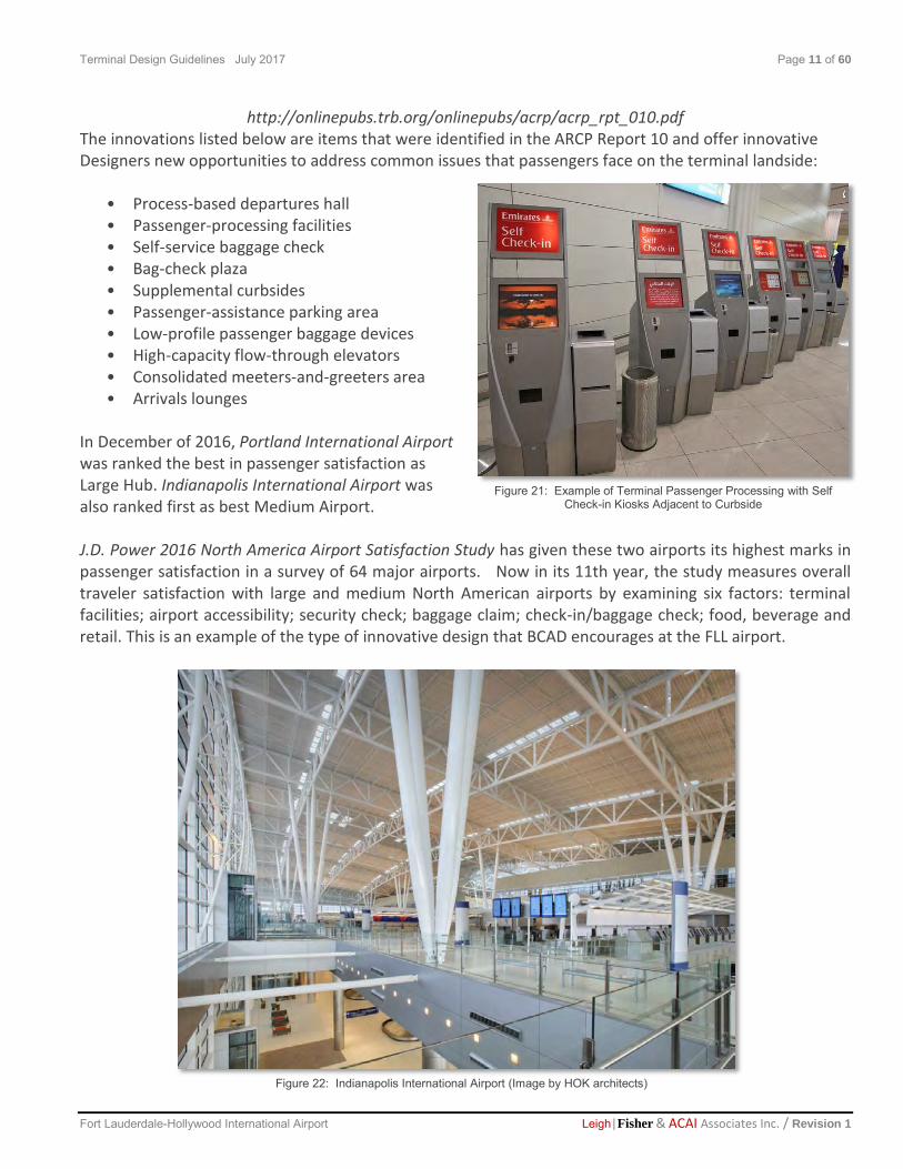
http://onlinepubs.trb.org/onlinepubs/acrp/acrp_rpt_010.pdf The innovations listed below are items that were identified in the ARCP Report 10 and offer innovative Designers new opportunities to address common issues that passengers face on the terminal landside:
• Process-based departures hall • Passenger-processing facilities • Self-service baggage check • Bag-check plaza • Supplemental curbsides • Passenger-assistance parking area • Low-profile passenger baggage devices • High-capacity flow-through elevators • Consolidated meeters-and-greeters area • Arrivals lounges
In December of 2016, Portland International Airport was ranked the best in passenger satisfaction as Large Hub. Indianapolis International Airport was also ranked first as best Medium Airport. J.D. Power 2016 North America Airport Satisfaction Study has given these two airports its highest marks in passenger satisfaction in a survey of 64 major airports. Now in its 11th year, the study measures overall traveler satisfaction with large and medium North American airports by examining six factors: terminal facilities; airport accessibility; security check; baggage claim; check-in/baggage check; food, beverage and retail. This is an example of the type of innovative design that BCAD encourages at the FLL airport.
Figure 21: Example of Terminal Passenger Processing with Self Check-in Kiosks Adjacent to Curbside
Figure 22: Indianapolis International Airport (Image by HOK architects)
Terminal Design Guidelines July 2017 Page 12 of 60
Fort Lauderdale-Hollywood International Airport Leigh|Fisher & ACAI Associates Inc. / Revision 1
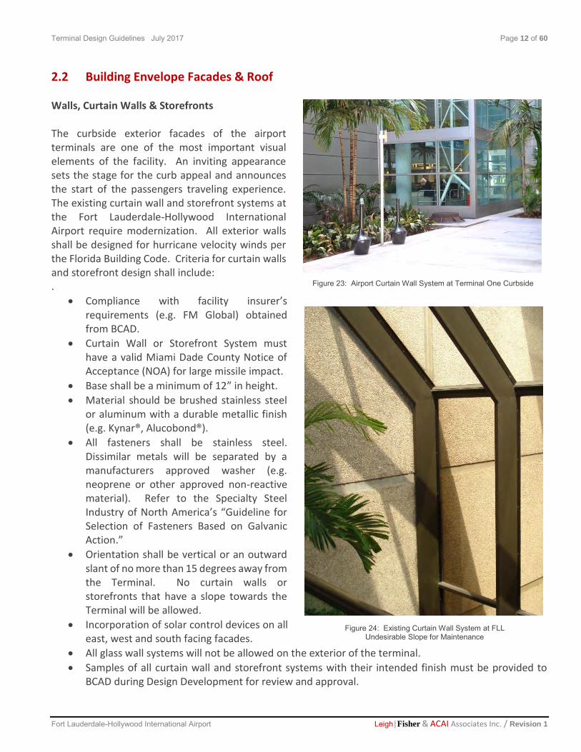
2.2 Building Envelope Facades & Roof Walls, Curtain Walls & Storefronts The curbside exterior facades of the airport terminals are one of the most important visual elements of the facility. An inviting appearance sets the stage for the curb appeal and announces the start of the passengers traveling experience. The existing curtain wall and storefront systems at the Fort Lauderdale-Hollywood International Airport require modernization. All exterior walls shall be designed for hurricane velocity winds per the Florida Building Code. Criteria for curtain walls and storefront design shall include:
.
Compliance with facility insurer’s requirements (e.g. FM Global) obtained from BCAD.
Curtain Wall or Storefront System must have a valid Miami Dade County Notice of Acceptance (NOA) for large missile impact.
Base shall be a minimum of 12” in height.
Material should be brushed stainless steel or aluminum with a durable metallic finish (e.g. Kynar®, Alucobond®).
All fasteners shall be stainless steel. Dissimilar metals will be separated by a manufacturers approved washer (e.g. neoprene or other approved non-reactive material). Refer to the Specialty Steel Industry of North America’s “Guideline for Selection of Fasteners Based on Galvanic Action.”
Orientation shall be vertical or an outward slant of no more than 15 degrees away from the Terminal. No curtain walls or storefronts that have a slope towards the Terminal will be allowed.
Incorporation of solar control devices on all east, west and south facing facades.
All glass wall systems will not be allowed on the exterior of the terminal.
Samples of all curtain wall and storefront systems with their intended finish must be provided to BCAD during Design Development for review and approval.
Figure 24: Existing Curtain Wall System at FLL Undesirable Slope for Maintenance
E
Figure 23: Airport Curtain Wall System at Terminal One Curbside
Terminal Design Guidelines July 2017 Page 13 of 60
Fort Lauderdale-Hollywood International Airport Leigh|Fisher & ACAI Associates Inc. / Revision 1
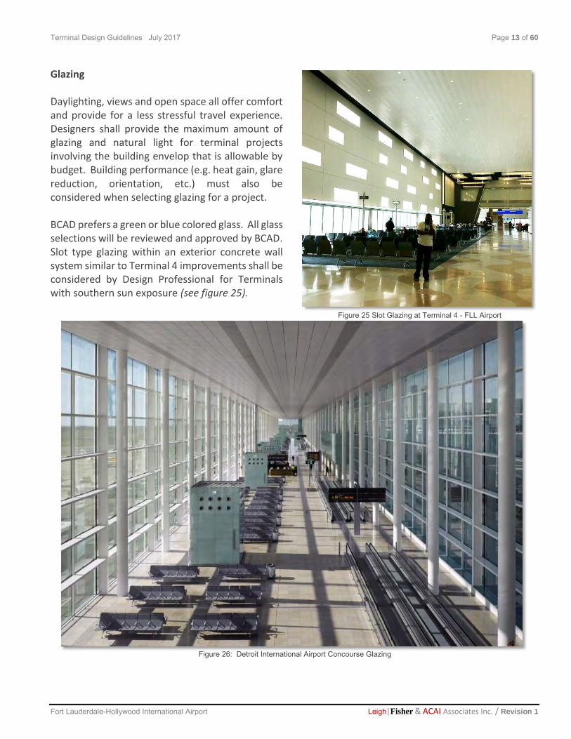
Glazing Daylighting, views and open space all offer comfort and provide for a less stressful travel experience. Designers shall provide the maximum amount of glazing and natural light for terminal projects involving the building envelop that is allowable by budget. Building performance (e.g. heat gain, glare reduction, orientation, etc.) must also be considered when selecting glazing for a project. BCAD prefers a green or blue colored glass. All glass selections will be reviewed and approved by BCAD. Slot type glazing within an exterior concrete wall system similar to Terminal 4 improvements shall be considered by Design Professional for Terminals with southern sun exposure (see figure 25).
Figure 25 Slot Glazing at Terminal 4 - FLL Airport
Figure 26: Detroit International Airport Concourse Glazing

Terminal Design Guidelines July 2017 Page 14 of 60
Fort Lauderdale-Hollywood International Airport Leigh|Fisher & ACAI Associates Inc. / Revision 1
Terminal Entrances Design Professionals shall comply with the following requirements for all publicly accessible Airport Terminal Entrances:
“Florida Americans With Disabilities Accessibility Implementation Act.” per Florida State Statutes 553.501 – 553.14 Web link:
http://www.leg.state.fl.us/statutes/index.cfm?App_mode=Display_Statute&Search_String=&URL=0500-0599/0553/0553PARTIIContentsIndex.html
Design Features that Architects and Engineers should consider at the Airport Terminal Entrances include the following:
Automatic double sliding doors at exterior vestibule entrances
Flush mounted thresholds
Air Curtains either recessed into the ceiling or designed into the entry for enhanced energy performance at all exterior vestibule entrances
No Carpet Tile at entrances
Minimize grooved or textured surfaces that may cause noise from rolling luggage
Coordinate the Integration of Airport Signage with BCAD’s Signage Consultant
Figure 27: JFK International Airport Entry
Figure 28: Air Curtain Incorporated into Curtain Wall at Barcelona International Airport Entry

Terminal Design Guidelines July 2017 Page 15 of 60
Fort Lauderdale-Hollywood International Airport Leigh|Fisher & ACAI Associates Inc. / Revision 1
Terminal Roofing
All proposed modifications to the existing roofing systems at the airport terminals must be approved by and coordinated with BCAD. The following criteria must be incorporated for all roofing designs:
Any existing warranty of the roofing system must be maintained if the roof is not replaced (e.g. Terminals that were recently reroofed).
Innovative but proven roofing designs will be considered
New roofing systems will carry a 20 year warranty
All roof assemblies and products must have a valid Miami Dade Notice of Acceptance (NOA)
All Roofing systems must be FM Global approved
A minimum R-value of at least 19.0 shall be provided uniformly across the entire roof area
A single ply system (90 mil thick) with white, highly reflective surface is preferred by BCAD
Exposed metal roofs may be considered by BCAD at terminal to terminal connectors and walkways
All roofed areas of the Airport Terminal will be accessible by aluminum roof hatches (with current Miami-Dade NOA) and external wall mounted transfer ladders that are galvanized or aluminum
Lighting protection systems will be provided at all roof locations
Roof equipment shall be screened from view
Antenna farms shall be coordinated with the BCAD Telecommunications Department and FAA.
Figure 29: Fort Lauderdale-Hollywood International Airport
Figure 30: Bilco Type S Ladder Access Enhanced Performance Roof Hatch

Terminal Design Guidelines July 2017 Page 16 of 60
Fort Lauderdale-Hollywood International Airport Leigh|Fisher & ACAI Associates Inc. / Revision 1
2.3 Materials and Finishes
Aesthetics, durability, maintainability and sustainability will be the key drivers for all materials and finishes used in all Fort Lauderdale-Hollywood International Airport Terminal modernization projects. Architects, Engineers and Interior Designers must incorporate materials and finishes that will be very durable and abuse resistant. All materials and finishes must be able to maintain their aesthetic appeal when exposed to high occupant use and potential impact by traveler’s luggage. Design Professionals shall submit samples of all materials and finishes for review and approval by the BCAD. Lighter color materials and finishes that highlight the natural colors of South Florida are preferred.
Curbside Walkways All exterior flooring and sidewalks shall be concrete with a broom finish. No patterned surface finishes will be allowed. No poured area of concrete shall be larger than 10’ x 10’. The minimum thickness for all poured concrete sidewalks shall be 5”. At entrances and along the Terminal’s exterior wall Designer’s should consider a thickened edge slab to help prevent cracking and support BCAD’s maintenance lift. Special attention by Design Professionals shall be given to control and expansion joints. All joints shall be coordinate with the handrail modules. A 1/2" wide joint must be provided around every column.
Figure 31: Curbside Concrete Sidewalks at Indianapolis International Airport by HOK

Terminal Design Guidelines July 2017 Page 17 of 60
Fort Lauderdale-Hollywood International Airport Leigh|Fisher & ACAI Associates Inc. / Revision 1
Curbside Handrails Exterior handrails shall be stainless steel with heavy galvanized metal posts and pickets to match the existing handrail system (see figure 32). Dissimiliar metal fasteners will not be allowed in order to avoid galvanic reactions. Design Professionals shall ensure that the module of the railing posts align with concrete joints. Curbside Stanchions Stanchions (utility posts) located on curb side shall be black aluminum post, with black removable rubber base, and black belt (see figure 33). Curbside Bollards Bollards shall be stainless steel with a sloped top. The protective bollards at Fort Lauderdale-Hollywood International Airport are part of an engineered plan. Specific information regarding their design and performance criteria shall be obtained by design professionals from BCAD (see figure 34). Curbside Concrete Columns At the bottom 8’-0” of all exposed concrete columns design professionals shall provide a protective finish to prevent soiling and staining of the concrete due to passenger use. An exterior grade textured stainless steel column enclosure or other class 5 BCAD approved finish shall be considered by Architects and must be approved the BCAD Project Review Committee (PRC). Curbside Soffits Open soffits or exposed structure will not be allowed due to bird perching and nesting problems. Exterior Terminal soffits shall be clad with a metal panel system that one person can remove and repair (see figure 35). The panels shall be corrosion resistant due to humidity and salt air conditions.
Figure 32: Existing Handrails at Fort Lauderdale-Hollywood
International Airport
Figure 34: Curbside Bollards at Fort Lauderdale-Hollywood International Airport
Figure 35: Existing Metal Soffits at Fort Lauderdale-Hollywood International Airport
Figure 33: Standard BCAD
Curbside Stanchion

Terminal Design Guidelines July 2017 Page 18 of 60
Fort Lauderdale-Hollywood International Airport Leigh|Fisher & ACAI Associates Inc. / Revision 1
Terminal Entry Flooring Tiled entries will not be allowed in any Fort Lauderdale-Hollywood International Airport terminal project (see figure 36). Flooring at all entries will be a recessed stainless steel grate that can be removed for maintenance and cleaning. (e.g. Floorometry, see figures 37-39).
Samples of all proposed vestibule entrance flooring shall be provided to BCAD during Design Development for review and approval.
Figure 37: Proposed FLL Terminal
Vestibule Entrance Flooring
Figure 36: Existing FLL Airport Terminal Entry
Figure 38: Proposed Alternate FLL Terminal Vestibule Entrance Floor
Figure 39: Proposed FLL Terminal Vestibule Entrance Flooring

Terminal Design Guidelines July 2017 Page 19 of 60
Fort Lauderdale-Hollywood International Airport Leigh|Fisher & ACAI Associates Inc. / Revision 1
Terminal Flooring Poured in place terrazzo flooring will be used in the primary circulation paths of the terminals including public stairways and baggage claim areas. Primary divider strips will be 1/4” wide aluminum. Secondary divider joints will be 1/8” or 1/16” wide aluminum. Areas of continuous terrazzo flooring will not be larger than 10’ x 10’. Smaller areas are encouraged to help minimize cracking. Designers shall provide antifracture and waterproofing membranes below the terrazzo to control potential cracking and moisture problems. The base color terrazzo specified by BCAD (see figures 40) is as follows:
Terroxy Resin Systems: TM#10 – 2048
Natural Finish 800 Grit with Terra Shine
#3 Epoxy: 2001 White
Chips: - 50% Crystal Glass #0,1 - 40% Blanco Mexicano #0,1 - 10% Classic MOP #2,3
Provisions shall be provided for the floor substrate in order to assure a flush and level floor between terrazzo and other floor applications (e.g. carpet tile, etc.). Terrazzo flooring will not be allowed in restrooms due to ongoing problems with staining of the floors. Per BCAD, no pure surface coating or wax sealer shall be allowed. BCAD also reserves the right to request an artistic design for terrazzo flooring in the terminals. See figure 41 which shows cropped sections of artistic terrazzo floor recently installed at FLL.
Figure 41: Terrazzo Floor at Fort Lauderdale-Hollywood International Airport
Figure 40: BCAD Terrazzo Resin Systems TM#10-2048
Figure 41a: Section of Terrazzo
Floor Art from Thomas Sayre’s Mangrove Islands

Terminal Design Guidelines July 2017 Page 20 of 60
Fort Lauderdale-Hollywood International Airport Leigh|Fisher & ACAI Associates Inc. / Revision 1
Modular Carpet tile 36” x 36” (or 100 cm x 100 cm) with PVC-free cushion backing will be the preferred material at all concourse holding areas. Floor materials that will not be allowed in public areas include:
Rolled carpeting
Engineered wood
Vinyl tile
Vinyl sheet
Floor base materials within the Terminal Concourses will be from 8” up to 12” in height (depending on existing terminal finishes). Designers will provide a terrazzo base where terrazzo flooring meets a wall. Other hard and abuse resistant base materials will be allowed provided a color sample of the material and a material product sheet is submitted for review during the Design Development phase. Floor base materials that will not be allowed include rubber, vinyl and wood.
Figure 42: Indianapolis International Airport by HOK – Terrazzo Flooring at New Terminal

Terminal Design Guidelines July 2017 Page 21 of 60
Fort Lauderdale-Hollywood International Airport Leigh|Fisher & ACAI Associates Inc. / Revision 1
Terminal Walls All airport terminal walls shall be of noncombustible materials, such as metal studs, channels, caps, and bracing. All gypsum board will have a minimum thickness of 5/8". Fire resistance ratings shall be designed per Florida Building Code requirements. Modular demountable wall systems with a non-perforated powder coating finish are preferred by BCAD. They may be incorporated into the first 10’-0” of wall height. Wood framing will not be allowed for use in any walls types. Colors for all painted wall surfaces will be reviewed and approved by the BCAD PRC. Exposed CMU walls will not be permitted. BCAD’s preferred terminal wall painted finish is egg shell. Stainless steel corners guards (2” x 2”) min., 14 gauge, type 304 screw-on), shall be provided at all wall corners. Terminal Ceilings Painted gypsum board ceilings will be allowed throughout the Terminals. Suspended ceiling grids with 2’ x 2’ and 2’ x 4’ acoustical lay-in tiles may also be used. The use of extra micro perforated metal panels (6” x 16”), on high ceilings is encouraged. Designers should also provide differentiated ceiling heights as well as material and color variation in order to enhance the passengers traveling experience through the FLL terminals. Linear metal ceilings with a wood-effect finish and other well designed ceiling elements will also be allowed. Use of suspended ceiling systems with individual pieces (e.g. flanges) that require balance or manual configuration will not be allowed. BCAD will review all proposed ceiling materials and provide written approval for their use.
Figure 44: Indianapolis International Airport by HOK Ceiling at Baggage Claim Area
Figure 43: Indianapolis International Airport by HOK Ceiling at Security Screening Area
Terminal Design Guidelines July 2017 Page 22 of 60
Fort Lauderdale-Hollywood International Airport Leigh|Fisher & ACAI Associates Inc. / Revision 1
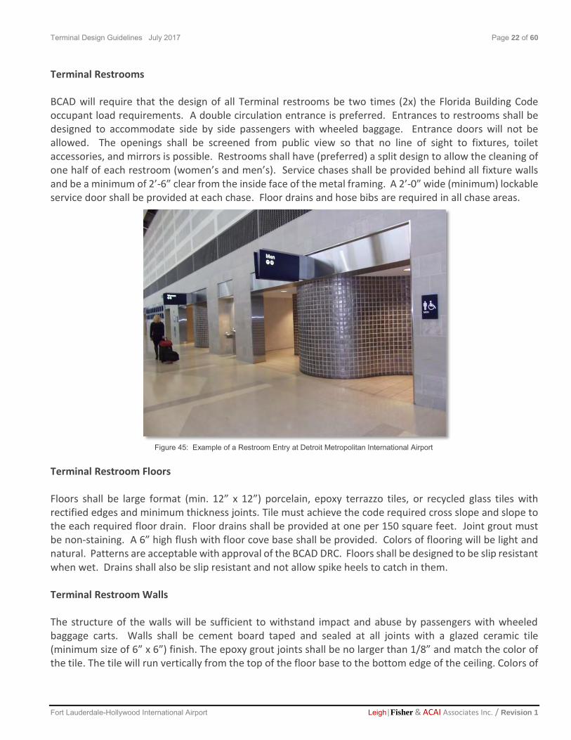
Terminal Restrooms BCAD will require that the design of all Terminal restrooms be two times (2x) the Florida Building Code occupant load requirements. A double circulation entrance is preferred. Entrances to restrooms shall be designed to accommodate side by side passengers with wheeled baggage. Entrance doors will not be allowed. The openings shall be screened from public view so that no line of sight to fixtures, toilet accessories, and mirrors is possible. Restrooms shall have (preferred) a split design to allow the cleaning of one half of each restroom (women’s and men’s). Service chases shall be provided behind all fixture walls and be a minimum of 2’-6” clear from the inside face of the metal framing. A 2’-0” wide (minimum) lockable service door shall be provided at each chase. Floor drains and hose bibs are required in all chase areas. Terminal Restroom Floors Floors shall be large format (min. 12” x 12”) porcelain, epoxy terrazzo tiles, or recycled glass tiles with rectified edges and minimum thickness joints. Tile must achieve the code required cross slope and slope to the each required floor drain. Floor drains shall be provided at one per 150 square feet. Joint grout must be non-staining. A 6” high flush with floor cove base shall be provided. Colors of flooring will be light and natural. Patterns are acceptable with approval of the BCAD DRC. Floors shall be designed to be slip resistant when wet. Drains shall also be slip resistant and not allow spike heels to catch in them. Terminal Restroom Walls The structure of the walls will be sufficient to withstand impact and abuse by passengers with wheeled baggage carts. Walls shall be cement board taped and sealed at all joints with a glazed ceramic tile (minimum size of 6” x 6”) finish. The epoxy grout joints shall be no larger than 1/8” and match the color of the tile. The tile will run vertically from the top of the floor base to the bottom edge of the ceiling. Colors of
Figure 45: Example of a Restroom Entry at Detroit Metropolitan International Airport

Terminal Design Guidelines July 2017 Page 23 of 60
Fort Lauderdale-Hollywood International Airport Leigh|Fisher & ACAI Associates Inc. / Revision 1
wall tile will be light and natural. Patterns may be allowed but will require review and approval by the BCAD Project Review Committee. Terminal Restroom Ceilings Ceilings will be a smooth and hard surface. Acoustical tile and metal ceiling tiles are not allowed. Variations in height are allowed with a minimum of 8’-0”. Provide 18” x 18” (minimum) lockable door panels for access to services above the ceiling. All lighting within the ceiling shall be fully recessed and flush with the face of the ceiling. Terminal Toilet Partitions BCAD’s toilet stall size is 3’-6”W x 6”-0”D. No stall sizes shall be less than 3’-0”W x 5’-6”D. Toilet partitions shall be ceiling hung (unless is structurally unsuitable). They shall have an embossed diamond textured stainless steel finish. Panels, ceiling pilasters, and doors shall be one inch thick and also fabricated from stainless steel. All hardware will be stainless steel. Wall, pilaster brackets and door hinges will be continuous. Gaps between doors and panels will not be accepted. Design Professionals shall provide ADA accessible compartments and stalls as required.
Figure 46: Example of Existing Ceiling Mounted Stainless Steel Partitions in Restroom at FLL Terminal 1 Concourse “B”

Terminal Design Guidelines July 2017 Page 24 of 60
Fort Lauderdale-Hollywood International Airport Leigh|Fisher & ACAI Associates Inc. / Revision 1
Terminal Toilet Accessories All toilet accessories shall be stainless steel and comply with ADA and FBC Code requirements. They may include but not be limited to the following:
Grab Bars
Toilet tissue dispensers
Toilet seat covers dispensers
Coat hooks
Waste receptors
Sanitary napkin disposal units
Feminine hygiene vending machine
Utility shelf units (24”L x 4”D in each toilet stall)
No wood blocking for the mounting of any device will be allowed. All wall reinforcement for the attachment of toilet room accessories shall be galvanized metal. Mirrors shall be provided over lavatories. Baby change units must be provided in all restrooms. Hand dryers shall be Dyson Airblade (or approved similar). Soap dispenser shall be non-touch foam type powered by low voltage. They shall be integrated into the trough sink’s countertop area along with a trash chute opening for paper towel disposal. The paper towel dispenser shall be installed over the trough sink area and aligned with the trash chute opening. A janitor service closet will be provided at for each group of restrooms. The mop receptor shall be 24” x 24” x 12”. A rough plated faucet with a hose end, pail hook, vacuum breaker and stops shall also be provided. Mop and broom holders will be designed to hang on adjacent walls. Terminal Restroom Fixtures Lavatories shall be a double trough type with a continuous shelf above. Material shall be corian or other approved solid surface material (see figure 48). Color shall be integral and coordinated with wall and floor tile finishes. Lavatories shall be mounted with a wall support system sufficient to resist a 1000 pounds pull out force. Paper towel dispensers shall be provide between trough lavatories. They shall be hardwired with a sensor for hands-free operation. Faucets shall only provide cold water for hand washing. They shall be hands-free and powered by low voltage. Stainless steel mechanically fastened handbag hooks capable of supporting 25 lbs. (min.) shall also be provided.
Figure 48: Example of a Continuous Sink
Figure 47: Dyson Airblade Hand Dryer
Terminal Design Guidelines July 2017 Page 25 of 60
Fort Lauderdale-Hollywood International Airport Leigh|Fisher & ACAI Associates Inc. / Revision 1
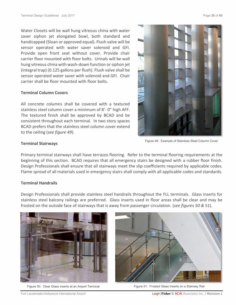
Water Closets will be wall hung vitreous china with water saver siphon jet elongated bowl, both standard and handicapped (Sloan or approved equal). Flush valve will be sensor operated with water saver solenoid and GFI. Provide open front seat without cover. Provide chair carrier floor mounted with floor bolts. Urinals will be wall hung vitreous china with wash-down function or siphon jet (integral trap) (0.125 gallons per flush). Flush valve shall be sensor operated water saver with solenoid and GFI. Chair carrier shall be floor mounted with floor bolts. Terminal Column Covers All concrete columns shall be covered with a textured stainless steel column cover a minimum of 8’- 0” high AFF. The textured finish shall be approved by BCAD and be consistent throughout each terminal. In two story spaces BCAD prefers that the stainless steel column cover extend to the ceiling (see figure 49). Terminal Stairways Primary terminal stairways shall have terrazzo flooring. Refer to the terminal flooring requirements at the beginning of this section. BCAD requires that all emergency stairs be designed with a rubber floor finish. Design Professionals shall ensure that all stairways meet the slip coefficients required by applicable codes. Flame spread of all materials used in emergency stairs shall comply with all applicable codes and standards. Terminal Handrails Design Professionals shall provide stainless steel handrails throughout the FLL terminals. Glass inserts for stainless steel balcony railings are preferred. Glass inserts used in floor areas shall be clear and may be frosted on the outside face of stairways that is away from passenger circulation. (see figures 50 & 51).
Figure 49: Example of Stainless Steel Column Cover
Figure 50: Clear Glass inserts at an Airport Terminal Figure 51: Frosted Glass Inserts on a Stairway Rail

Terminal Design Guidelines July 2017 Page 26 of 60
Fort Lauderdale-Hollywood International Airport Leigh|Fisher & ACAI Associates Inc. / Revision 1
Terminal Water Fountains Water fountains shall be provided frequently throughout the Fort Lauderdale-Hollywood International Airport terminals. They shall be the same manufacturer make and model number in each terminal. See water fountains recently installed at Terminal 4 on figure 52. Design Professionals shall confirm the make and model number with BCAD. BCAD’s preferred location is between restrooms and near food courts. Water fountains including water bottle fillers option are encouraged (recently installed on the new Concourse A). All water fountains shall be ADA compliant. Other requirements Additional passenger service areas shall be incorporated into the Terminal’s layout: family restrooms, breast -feeding rooms and pet relief areas. Terminal Defibrillators Recessed wall mounted defibrillator cabinets shall be provided throughout the airport terminals with any signage that may be required by code. The manufacturer’s make and model number shall be the same for all terminals and approved by BCAD (Phillips HeartStart FRx, with carrying case #989803139251) or approved equal. At least one, pre-security, and one, post security shall be required on each floor in the following areas:
Concourses
Ticketing lobby
Baggage claim area ADA Accessibility Codes The current edition of the Florida Building Code (FBC) shall be utilized for all ADA code compliance requirements. Design Professionals shall be responsible for compliance with all ADA code requirements. Florida Building Code: http://www2.iccsafe.org/states/florida_codes/
Figure 52: Existing Drinking Fountain at Fort Lauderdale
Hollywood International Airport
Figure 52a: Example of a wall mounted recessed Defibrillator cabinet

Terminal Design Guidelines July 2017 Page 27 of 60
Fort Lauderdale-Hollywood International Airport Leigh|Fisher & ACAI Associates Inc. / Revision 1
2.4 Furnishings, Fixtures and Equipment
Curbside The curbside appeal for passengers traveling through Fort Lauderdale-Hollywood International Airport is lacking. Furnishing, fixtures and equipment are inconsistent, cluttered and not visually appealing. Design Professionals will need to consider and provide the following curbside design elements when improvement projects are executed during terminal modernization projects:
Standard outdoor seating at each terminal shall be a black metal. Design professionals shall obtain the manufacturer make and model from BCAD (see figure 22).
Standard trash cans shall be explosion resistant stainless steel with a brushed with abraded finish.
Screened storage areas designed for wheel chairs and luggage cart storage (see figure 23).
Outdoor kiosks shall be made of durable materials that can withstand Florida’s harsh outdoor conditions (e.g. rain, wind, humidity, salt air and UV light). Design Professionals shall consider placement of outdoor kiosks under shade and rain screen devices.
Figure 21: Existing Terminal Curbside
Figure 22: BCAD Standard Curbside Bench
Figure 23: Existing wheel chairs with no screened storage Figure 24: Example of a Self Service Kiosk for Luggage Check-in

Terminal Design Guidelines July 2017 Page 28 of 60
Fort Lauderdale-Hollywood International Airport Leigh|Fisher & ACAI Associates Inc. / Revision 1
The curbside design and organization of furnishings fixtures and equipment for the “in- passenger service and convenience award winning” Indianapolis International Airport is a good example of “Design Excellence” that Professionals should pursue for the Fort Lauderdale-Hollywood International Airport Terminal improvement projects.
Designers should consider increasing the overhang area of each terminal. An increased covered/sheltered area for passenger drop-off is desired. A row of bollards could be installed to allow a covered area for vehicles to unload passengers without them having to dodge other passengers and baggage by those attempting to enter the terminal. Being on the terminal side of the bollard row would provide a wide aisle for them to find their way to the right curbside baggage check-in, wheelchair storage, ticketing kiosks and entry into the terminal. This would allow space for innovative design of curbside check-in kiosks (see figure 27).
Smoking Posts New Smoking posts shall be provided curbside for all terminals. No smoking is allowed within the FLL terminals. Smoking posts shall either be stainless steel or aluminum to prevent rust stains on the outdoor sidewalks. They must be located away from the terminal entries to avoid interference with passenger circulation and so that no second hand smoke enters the terminal (see figure 28).
Figure 25: Indianapolis International Airport by HOK Vehicular Curbside
Figure 26: Indianapolis International Airport by HOK Pedestrian Curbside
Figure 27: Example of Curbside Check-in at an Airport Terminal
Figure 28: Example of
stainless steel outdoor smoking
post

Terminal Design Guidelines July 2017 Page 29 of 60
Fort Lauderdale-Hollywood International Airport Leigh|Fisher & ACAI Associates Inc. / Revision 1
Terminal Side The furniture, fixtures and equipment within the Fort Lauderdale-Hollywood International Airport will require upgrades when terminal improvement projects are performed. Beginning with the passenger processing, all self service check-in kiosks will be standardized by BCAD. Design Professionals will comply to the following requirements:
Coordinate with BCAD the selected manufacturer make and model for airline e-ticketing kiosks
Standardized spacing of all kiosks
Design an effective arrangment of kiosks for easy passenger processing
Center align all kiosk groupings in FLL Terminals on the adjacent wall
E-Ticketing kiosks shall be connected in series to a bank, minimizing floor penetrations and permanent damage of terrazzo floors (See figure 29)
Figure 30: Example of E-ticketing Kiosk Configuration
Figure 29: Example of existing FLL E-ticketing Kiosks connected in series to a bank.

Terminal Design Guidelines July 2017 Page 30 of 60
Fort Lauderdale-Hollywood International Airport Leigh|Fisher & ACAI Associates Inc. / Revision 1
Terminal Ticket Counters The existing FLL ticket counters within the terminals are out dated (see figure 31). New design ideas and solutions shall be provided during terminal modernization projects by Design Professionals. All new ticket counters shall be ADA accessible. A diagrammatic concept for a new FLL service counter has been provided for reference (see figures 32 & 34). Variations of this concept will be allowed by BCAD. All proposed designs must be submitted for review by the BCAD PRC. Ticket counters shall accommodate two personnel from the airlines. Their minimal work area shall be 30” wide (2’-6”). The ADA accessible area shall be in the middle of the casework structure. The base of the ticket counter shall have a toe kick front
Figure 32: Side Elevation of New Concept for FLL Terminal Ticket Counter
Figure 31: Example of existing Terminal ticket counters

Terminal Design Guidelines July 2017 Page 31 of 60
Fort Lauderdale-Hollywood International Airport Leigh|Fisher & ACAI Associates Inc. / Revision 1
and back with a 6” high abraded stainless steel kick plate on all sides. The kick plate shall be mechanically attached with stainless steel fasteners that are flush with the face of the kick plate. Standard abraded stainless steel finishes (see figure 33) that BCAD may allow include but shall not be limited to the following:
Non-directional
Random swirl
Angel hair
Bead blasted All tops of the service counters shall be a solid surface material. The color and material selection for all may vary by terminal and must be approved by the BCAD PRC. Behind the service counter Designers shall provide a 30” high horizontal band where airlines will be able to locate their logos or flat screen monitors. The centerline height of this band shall be 80”. Above and below this band a veneer-finished modular wall system shall be provided to reinforce the concept of a standardized band. Tenant logos and graphics shall be metal or opaque acrylic. Uppercase letters shall not be higher than 14” and lowercase letters shall not exceed 10” in height. Screens will not be allowed to exceed the 30” zone (see figure 34). Background wallcoverings are acepted if receiving PRC approval. Self-service or attended baggage check-in counters are new features offered by the airlines companies. Design and layout has to be approved by PRC (see figure 34).
Figure 34: Side Elevation of New Concept for FLL Terminal Ticket Counter
Figure 33: Typical Abraded Stainless Steel Finishes
Figure 34: Terminal Ticketing and Baggage Check-in Counters

Terminal Design Guidelines July 2017 Page 32 of 60
Fort Lauderdale-Hollywood International Airport Leigh|Fisher & ACAI Associates Inc. / Revision 1
Terminal Concourse Gate Podium Some of the existing FLL concourse gates have old gate podiums (see figure 35). New ADA accessible gate podiums shall be provided in all terminal modernization projects. A concept diagram for a new FLL gate podium has been provided for reference (see figure 36). Variations of this concept may be allowed by BCAD (see figure 37). All proposed designs must be submitted for review by the BCAD PRC. Behind the gate podium and set 6” from the back wall there shall be a monitor support structure (see figure 36). The main gate podium casework shall be located on the centerline of the monitor support structure. The shell of the casework shall be 5’-6” in width. It shall be located adjacent to the secure door for the gate which may be to the right or left of the service counter. The base of the counter shall have a toe kick front and back, made of brushed stainless steel kick plate on all sides. The kick plate shall be mechanically attached with stainless steel fasteners that are flush with the face of the kick plate. All tops of the service counters shall be a solid
Figure 36: Ticketing and baggage check in counters
Figure 35: Example of Existing Concourse Gate Podiums

Terminal Design Guidelines July 2017 Page 33 of 60
Fort Lauderdale-Hollywood International Airport Leigh|Fisher & ACAI Associates Inc. / Revision 1
surface material. The color and material selection for all gate counter finishes and casework may vary by terminal and must be submitted for approval by the BCAD DRC. The back of the counter shall be open to receive a casement insert, with open shelves and ventilated locked compartiments for computers. Access panels to power and data connections are recommended (see figure 37).
Terminal Ticket Counter Stanchions & Queuing Signage The design layout of stanchions shall be considered by Design Professionals for all terminal queues. Stanchions shall be made of brushed aluminum (satin) finish and be of the retractable belt type. They shall be Single Line Visiontron (part # 300-SS) or a comparable vendor. The color of the retractable belts shall be “Navy” (Visiontron Custom Dark Blue Belt or equivalent) or BCAD approved airlines customized belt with logo. All stanchions posts must be uniform. Hard Panels Stanchions shall also be brushed aluminum, with frosted ¼”thick acrylic material. Both stanchions and panels shall be compatible systems. Ticket Counter queuing signage shall be 14" x 11" engraved plastic in a frame that attaches to the stanchion posts, consistent with the style of the stanchions (see figure 38).
Figure 37: Approved FLL concept for new service counter at Concourse G gates
Figure 38: Stanchions, Hard Panels and Signage

Terminal Design Guidelines July 2017 Page 34 of 60
Fort Lauderdale-Hollywood International Airport Leigh|Fisher & ACAI Associates Inc. / Revision 1
Terminal Concourses Seating
Gate seating shall be Herman Miller’s/HTS Eames Tandem Sling Seating (or approved equal). Seating must be configured back to back in groupings that are easy to move for BCAD maintenance personnel. They shall be arranged perpendicular to the concourse’s primary circulation route. The seat color material shall be black (see figure 39). Terminal Waste and Recycling Receptacles Waste receptacles shall be a brushed or other BCAD DRC approved stainless steel finish (see figure 40). Recycling receptacles shall also be of the same finish and clearly marked with standard symbols for recycled waste 40. No polished stainless steel receptacles shall be permitted due to unpleasant aesthetics after from prolonged use (see figure 41). Design Professionals shall confirm the make and model number of BCAD’s preferred waste and recycling can manufacturer. General waste trash cans openings must allow for pizza boxes disposal.
Figure 41: Existing Polished Stainless Steel (Scratched) Garbage Can at FLL
Figure 39: Eames Tandom Sling Seating
Figure 40: Preferred Garbage Cans for Waste and Recycling

Terminal Design Guidelines July 2017 Page 35 of 60
Fort Lauderdale-Hollywood International Airport Leigh|Fisher & ACAI Associates Inc. / Revision 1
Terminal Baggage Claim Improvements to the baggage claim areas shall include sloped carousels in lieu of the existing flat carousels (see figure 42). Adequate passenger circulation space shall be provided to accommodate peak passenger loads. Existing or new baggage cart rental units will be relocated so as to not interfere with the passengers retrieving luggage. All carousel surface areas shall be stainless steel. An abraded finish is preferred for the base are of the equipment. Designers shall consider the use of natural daylight and provide views to the outside where possible (see figure 43). Lighting levels shall comply with the baggage area space requirements provided in Section 2.6., Lighting. Seating shall be provided along the wall furthest from the luggage carousel.
Figure 42: Example of Preferred Sloped Baggage Carousel
Figure 43: Indianapolis International Airport by HOK - Example of Sloped Baggage Carousel and Baggage Claim Area
Terminal Design Guidelines July 2017 Page 36 of 60
Fort Lauderdale-Hollywood International Airport Leigh|Fisher & ACAI Associates Inc. / Revision 1
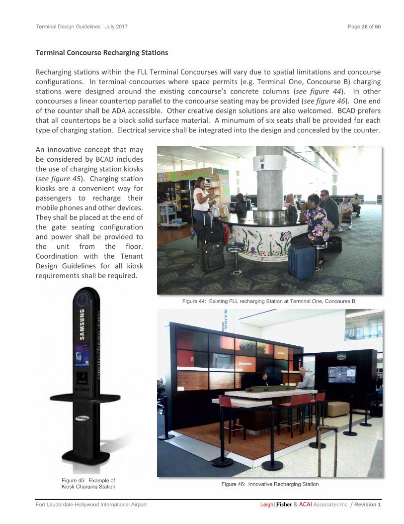
Terminal Concourse Recharging Stations Recharging stations within the FLL Terminal Concourses will vary due to spatial limitations and concourse configurations. In terminal concourses where space permits (e.g. Terminal One, Concourse B) charging stations were designed around the existing concourse’s concrete columns (see figure 44). In other concourses a linear countertop parallel to the concourse seating may be provided (see figure 46). One end of the counter shall be ADA accessible. Other creative design solutions are also welcomed. BCAD prefers that all countertops be a black solid surface material. A minumum of six seats shall be provided for each type of charging station. Electrical service shall be integrated into the design and concealed by the counter. An innovative concept that may be considered by BCAD includes the use of charging station kiosks (see figure 45). Charging station kiosks are a convenient way for passengers to recharge their mobile phones and other devices. They shall be placed at the end of the gate seating configuration and power shall be provided to the unit from the floor. Coordination with the Tenant Design Guidelines for all kiosk requirements shall be required.
Figure 44: Existing FLL recharging Station at Terminal One, Concourse B
Figure 46: Innovative Recharging Station Figure 45: Example of Kiosk Charging Station

Terminal Design Guidelines July 2017 Page 37 of 60
Fort Lauderdale-Hollywood International Airport Leigh|Fisher & ACAI Associates Inc. / Revision 1
Terminal Flight Information Displays (FIDS) FIDs shall be provided in all airport terminals. They shall be easily accessible and not obstruct passenger circulation. A vertical or portrait orientation is preferred by BCAD. In concourses an array of three FID screens shall be provided. Two shall display departure information and one shall display arrival information. In baggage claim areas an array of four FID screens shall be provided. Two shall display departure information and two shall display arrival information. The FIDs support structure shall be stainless steel and either free standing or suspended from the ceiling (BCAD’s preferred option). They may be independent (see figure 47) or incorporate other terminal elements such as location maps (see figure 48). The structure must have a protective bar barrier around its base. A clearly visible sign that does not compete with the Terminal wayfinding signage shall also be incorporated for easy identification. (see figure 47).
Figure 48: Example of FIDs at Indianapolis International Airport Figure 47: Example of a Standalone FIDs System with Clear Overhead Signage

Terminal Design Guidelines July 2017 Page 38 of 60
Fort Lauderdale-Hollywood International Airport Leigh|Fisher & ACAI Associates Inc. / Revision 1
Terminal Pay Phones Courtesy phones shall be provided in each terminal for passenger convenience. They may free standing, wall hung or sit down (see figure 49). Phones shall be located within a customer service alcove near baggage claim areas and gate seating areas. They must conform to all applicable codes, regulations and accessibility guidelines including signage. Additional requirements include but are not limited to the following:
Provide a TDD phone for the hearing impaired at each group.
Be stainless steel
Provide a continuous writing surface when wall hung
Designed with no sharp edges
Incorporate the same design within every terminal
Figure 50: Example of Airport Service Alcove BCAD’s preferred location for Public Phones and other Customer Service Items
Figure 49: Wall mounted pay phone

Terminal Design Guidelines July 2017 Page 39 of 60
Fort Lauderdale-Hollywood International Airport Leigh|Fisher & ACAI Associates Inc. / Revision 1
Terminal Elevators Passenger elevators shall have a stainless steel interior finish. Cargo elevator flooring shall be stainless steel plate with a diamond pattern. New passenger elevators should be designed as pass-thru type, with doors on front and back side. This will allow passengers with baggage not to have to enter the elevator and turn around with their bags to exit the elevator. This has been proven to speed up passenger processing and improve their traveling experience. Glass passenger cabs are encouraged with views to the terminal and exterior (see figure 51). Terminal Escalators Escalators will have a railing at the center and edge access at terrazzo flooring. Their underside shall be clad with stainless steel (see figure 52). Their sides may be glass or stainless steel (see figure 53). Wherever possible the dead space under escalators shall be furnished with benches for passenger seating. A minimum head clearance of 7’-6” shall be provided where seating under escalators is provided. Space under escalators less than 7”-6” shall be fully exclosed and accessible by a locked service door.
Figure 53: Example of an Airport escalator with glass railings
Figure 51: Airport Elevator Cab
Figure 52: Stainless Steel Underside of Escalator

Terminal Design Guidelines July 2017 Page 40 of 60
Fort Lauderdale-Hollywood International Airport Leigh|Fisher & ACAI Associates Inc. / Revision1
2.5 Signage, Wayfinding and Advertisements Signage Design Professionals conducting airport terminal work will be required to coordinate with BCAD’s Signage and Wayfinding Consultant for all designs that may impact the airports wayfinding signage. Architects and Interior Designers are encouraged to obtain a copy of the latest BCAD Wayfinding Guidelines that includes a wayfinding masterplan (see section 1.1). Other valid resource are the Aviation Industry Wayfinding and Signage Guidelines developed for the Airport Cooperative Research Program (ACRP). Terminal Side Advertisements Advertisement Signage will conform to all applicable codes and regulations and have been reviewed by BCAD to approve graphic design and content. It should adhere to theme guidelines by displaying the message in such a manner that conveys some aspect of the “your Portal to Paradise” theme which includes sun, sea, beaches, everglades environment, yachting, cruises, aviation and the arts. All airport signage for advertisements shall be:
Figure 56: Example of Airport Signage at Las Vegas Airport
Figure 55: Example of Preferred Advertising Signage
Figure 54: Example of Curbside Signage

Terminal Design Guidelines July 2017 Page 41 of 60
Fort Lauderdale-Hollywood International Airport Leigh|Fisher & ACAI Associates Inc. / Revision1
Securely fastened
Wall mounted with a vertical center at average level of 60-66” above finish floor
Show no exposed hardware
Repeat the same shape patterns and symmetry
Have stainless steel or powder coated aluminum frames
Have antiglare, matte finish screens or transparent view-though panels that shall be shatterproof Kinetic and digital imagery through plasma or flat screen signage shouldn’t compete for attention or cause extreme brightness. Shadows on backlights are not permitted as well as distraction of passengers from way finding and directional signs. Terminal way finding and life safety signage shall have precedence over all other airport terminal signage.

Terminal Design Guidelines July 2017 Page 42 of 60
Fort Lauderdale- Hollywood International Airport Leigh|Fisher & ACAI Associates Inc. / Revision 1
2.6 Lighting All lighting will be subject to review and approval by BCAD. Lighting should be designed to illuminate Terminals creatively without detracting from its services and wayfinding signage. It should also be as energy efficient as possible without compromising the design integrity or code required lighting levels. LED and other innovative lighting sources are recommended. Design Professionals shall incorporate lamps
with a CRI of at least 80 in applications where the color rendering of skin tones and merchandise is very important (e.g. concourses) Strobe lights, flashing lights and neon are prohibited. Lighting will not create any glare within the Terminal. Lighting will:
Be commercial-quality light fixtures approved by BCAD.
All lighting will comply with applicable local and national codes and regulations.
Energy Star rated lighting fixtures are preferred.
Lighting fixtures must not shine into the eyes of travelers or cause distraction. Other lighting considerations include:
Creative use of cove lighting, indirect lighting, LED ropes, backlighting or recessed fixtures are encouraged.
Figure 57: Example of Various Types of Lighting at Indianapolis International Airport Terminal by HOK
Figure 58: Existing FLL Cove Lighting
Example

Terminal Design Guidelines July 2017 Page 43 of 60
Fort Lauderdale- Hollywood International Airport Leigh|Fisher & ACAI Associates Inc. / Revision 1
Storefronts, signage and displays shall be illuminated with higher intensity to draw attention to the retail zone
Track lighting will not be allowed within Terminal areas.
Accentuating architectural elements such as columns.
Provide higher lighting levels along primary circulation routes
Visible linear fluorescents and sodium lamps will not be permitted.
All display cases must integrate shielded lighting and be vented properly. Lighting and Controls Based on recommendations by the International Energy Conservation Code (IECC) Code Development Committee, many proposed changes to the IECC are one step closer to translating into more energy efficient residential and commercial buildings. With only one round of public comment and the Final Action Hearings to go, the U.S. Department of Energy (DOE) is getting close to realizing its goal to achieve a 2012 IECC that is 30% more stringent than the 2006 IECC. Designing with ASHRAE 90.1-2010 standard will insure maximum energy-efficiency and preparedness for
the inevitable future requirements.
A brief comparison of the two codes is as follows:
CURRENT ASHRAE 90.1 - 2010
Space Watts per square foot
Baggage Area 1.00 0.76
Airport Concourse 0.60 0.36
Audience Seating N/A 0.54
Terminal-Ticket Counter 1.50 1.08
Daylighting N/A Required where primary side-lighted areas equals or
exceeds 250 square feet
In addition, all lighting fixtures will have the ability to respond to various inputs to provide the appropriate lighting level for the task required. Inputs will include, but are not limited to, occupancy sensors, photo sensors for daylighting control, timeclock control, dimming control and tuning control. LED will be the preferred light source, provided that the combined energy and maintenance savings of fixtures selected for a given application will pay for any increase in cost over a traditional light source, in a period not to exceed five years. Color temperature of all light sources are to be consistent throughout the complex and should be coordinated with the interior finishes. Color temperature of the lighting over the vanities with mirrors in all public bathrooms will between 2700˚K-3000˚K to insure that all passengers look their healthiest when visiting Fort Lauderdale.

Terminal Design Guidelines July 2017 Page 44 of 60
Fort Lauderdale- Hollywood International Airport Leigh|Fisher & ACAI Associates Inc. / Revision 1
Regardless of the light source selected, the CRI (color-rendering index), will not be less than 80 for all interior spaces. To minimize maintenance costs, lamp life for replacement four foot fluorescent lamps shall not be less
than 46,000 hours, and for new fixtures shall not be less than 60,000 hours (which requires a lamp and
ballast combination), unless special lighting requirements using shorter life lamps are necessary and no
long life source is available. For fixtures with native LED sources, L70 (the industry standard of
measurement of the number of hours of operation at which point the LEDs are at 70% of original output)
shall not be less than 50,000 hours.
Where it is possible, high ceilings on high transit areas are encouraged. Designers should work illumination of those spaces using indirect sources, leaving only sprinkler heads, smoke and CO2 detectors attached to the ceiling structure. This type of configuration facilitates re-lamping and maintenance. Grouping lighting fixtures in few locations also improves accessibility from the floor and provides more flexibility to concession's layout (See figures 59 & 60).
Figure 59: Example of Clearstory Lighting

Terminal Design Guidelines July 2017 Page 45 of 60
Fort Lauderdale- Hollywood International Airport Leigh|Fisher & ACAI Associates Inc. / Revision 1
Figure 60: Clearstory Lighting with Indirect Lighting

Terminal Design Guidelines July 2017 Page 46 of 60
Fort Lauderdale-Hollywood International Airport Leigh|Fisher & ACAI Associates Inc. / Revision 1
2.7 Public Art & Design The Fort Lauderdale-Hollywood International Airport has a Public Art & Design Program. Designated areas for public art within all of the Terminals have been established in the Fort Lauderdale-Hollywood International Airport Expansion Public Art Master Plan. Architects, Engineers and Interior Design Consultants will need to coordinate their airport terminal design efforts with the Public Art & Design Program to ensure that currently installed artworks are not impacted. In the event public art is part of a capital project, Consultants shall cooperate with the artist(s) and include the selected artist(s) as a design team member in the preliminary design and design phases of the Project. Consultants shall include in their designs the necessary infrastructure for the artworks, included, but not limited to lighting, foundations, structural supports, and electrical connections. Refer to figures 61 and 62 for samples of FLL artwork. Sculptures that may be placed on the floor in Terminal concourses should have a base of at least 8” high. Adequate clearance to allow BCAD’s maintenance lift must be coordinated by the design professionals if a floor sculpture or hanging piece of art is installed or will be installed within the Design scope of work boundary. Artwork may include, but is not limited to, the following:
Sculpture: free-standing, wall supported or suspended; kinetic, electronic
Murals or portable paintings
Fiberworks, neon, glass, mosaics, photographs, prints, calligraphy, sound, literary elements, film, holographic images, and video systems
Furnishings or fixtures, including but not limited to: gates, railings, lamps, signage, and seating, if created by artists as unique elements or limited editions
Artistic or aesthetic elements of the overall architecture if created by a professional artist or a design team that includes a professional visual artist
Flooring Design
Temporary artworks or installations that serve the purpose of providing community and educational outreach purposes
Figure 61: Existing FLL Photography by Clyde Butcher Photo “Dunes”
Figure 62: Existing FLL Wall Mural by Guy Harvey – Sunken Treasure
Figure 61: Existing FLL Photography by Clyde Butcher Photo “Dunes

Terminal Design Guidelines July 2017 Page 47 of 60
Fort Lauderdale-Hollywood International Airport Leigh|Fisher & ACAI Associates Inc. / Revision 1
2.8 Sustainability
Architects, Engineers and Interior Designers shall incorporate sustainable design practices and materials into the development of their airport terminal project. New public buildings in Broward County are required to pursue LEED certification. A transition to a High Performance Building (HPB) is one of BCAD’s long term goals. Designers should present sustainable project elements for review during the PRC process. Additional resource guides for sustainable design include the following:
• United States Green Building Council’s (USGBC) Leadership in Energy and Environmental Design for Commercial Interiors (LEED-CI)
http://www.usgbc.org/DisplayPage.aspx?CMSPageID=145 “LEED for Commercial Interiors is the green benchmark for the tenant improvement market. It is the recognized system for certifying high-performance green interiors that are healthy, productive places to work; are less costly to operate and maintain; and have a reduced environmental footprint. LEED for Commercial Interiors gives the power to make sustainable choices to tenants and designers, who do not always have control over whole building operations.” (Source: USGBC Commercial Interiors website)
• Florida Green Building Coalition (FGBC) Commercial Building
Standard http://www.floridagreenbuilding.org/commercial
“The intent of the FGBC Green Commercial Building Standard is to encourage building owners to adopt green and sustainable strategies during the design and construction of their project and to receive recognition for their efforts. The Florida Green Commercial Building Standard covers all commercial occupancies listed in the Florida Building Code.”
Clyde Butcher Dunes
Figure 63: Example of Green Space at Indianapolis International Airport by HOK

Terminal Design Guidelines July 2017 Page 48 of 60
Fort Lauderdale-Hollywood International Airport Leigh|Fisher & ACAI Associates Inc. / Revision 1
Sustainable design considerations should include:
• Sustainable Airport Manual (SAM) and other resource guides http://www.airportsgoinggreen.org/documents/CDASAMv3.2.pdf
• Selection of LED or other energy efficient lighting that is code complaint and within the parameters of BCAD’s product criteria
• Keep all non-emergency lighting off during non-business hours. • Install occupancy sensors in spaces that are not occupied regularly. • Specify the use of low emitting materials such as: adhesives, sealants, paints, coatings
and carpets http://www.greenguard.org/en/architectsDesigners.aspx
Specify the use of formaldehyde free materials • Select materials with recycled content, renewable materials and certified wood • Give preference to products fabricated or manufactured within Florida and the
Southeast Region of the United States • Zero use of CFC-based refrigerants in mechanical equipment • Incorporate green space into the Terminal’s curbside design (see figure 63) • Consider the life cycle of all material used and Cradle to Cradle certified products
http://www.c2ccertified.org/get-certified/product-certification
A visual connection from the interior to the exterior is very important for passenger comfort and well-being. Architects and Designers should consider the utilization of green walls outside of the Terminal that are visible from the interior. Green walls will be considered by BCAD as a “Sustainable Design” feature provided they are well designed and do not use a non-indigenous species of plant (see figures 65 & 66).
Figure 64: Solar Street Light
Figure 65: Green wall Example Figure 66: Green wall Detail

Terminal Design Guidelines July 2017 Page 49 of 60
Fort Lauderdale-Hollywood International Airport Leigh|Fisher & ACAI Associates Inc. / Revision 1
CHAPTER 3 Appendices
3.1 Guideline Revisions The Terminal DGM may be periodically updated by BCAD. It is recommended that this action be performed once a year. The Consultant shall verify with the BCAD Contract Administrator their possession and use of the latest version of the Terminal DGM. The following table provides a history of the Terminal DGM updates and releases.
TERMINAL DESIGN GUIDELINES MANUAL VERSIONS
Document Title Date Released
Terminal Design Guidelines Manual April 2012
Terminal Design Guidelines Manual Revision 1 July 2017
3.2 Definitions and Abbreviations The following Definitions and Abbreviations have been provided as an aid for understanding the Terminal Design Guidelines Manual. The Term or Acronym appears in bold case followed by its corresponding meaning or definition. A/E of Record Architect / Engineer responsible for the signing and sealing of the design documents AHJ Authority Having Jurisdiction EAP Airport Expansion Program BAS Building Automation System BCAD Broward County Aviation Department BIM Building Information Model BIP Building Improvement Project CADD Computer Aided Design and Drafting CIP Capital Improvement Projects Construction GM Construction Guidelines Manual

Terminal Design Guidelines July 2017 Page 50 of 60
Fort Lauderdale-Hollywood International Airport Leigh|Fisher & ACAI Associates Inc. / Revision 1
Consultant The individual or entity contracted by BCAD to complete a predetermined
scope of work at FLL
Curbside The area adjacent to but outside the terminals where passengers arrive and depart
Designer A Florida Licensed Professional or authorized representative thereof within
the fields of Architecture, Engineering and Interior Design FBC Florida Building Code
FIDS Flight Information Displays FLL Fort Lauderdale-Hollywood International Airport GIS Geographic Information System HPB High Performance Building
LOD Level of Detail required when preparing a Building Information Model (BIM) NTP Notice to Proceed
PRC Project Review Committee T1 Terminal One T2 Terminal Two T3 Terminal Three T4 Terminal Four Tenant DGM Tenant Design Guidelines Manual
Terminal The physical building space of the airport where passengers transfer between ground transportation and the facilities that allow them board and disembark from aircraft.
Terminal DGM Terminal Design Guidelines Manual
Terminal Design Guidelines July 2017 Page 51 of 60
Fort Lauderdale-Hollywood International Airport Leigh|Fisher & ACAI Associates Inc. / Revision 1
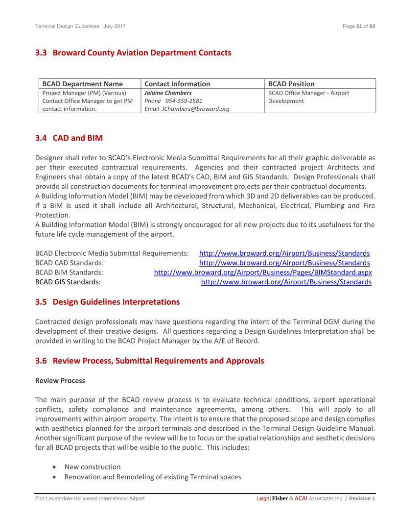
3.3 Broward County Aviation Department Contacts
BCAD Department Name Contact Information BCAD Position Project Manager (PM) (Various) Contact Office Manager to get PM contact information.
Jalaine Chambers Phone 954-359-2581 Email [email protected]
BCAD Office Manager - Airport Development
3.4 CAD and BIM Designer shall refer to BCAD’s Electronic Media Submittal Requirements for all their graphic deliverable as per their executed contractual requirements. Agencies and their contracted project Architects and Engineers shall obtain a copy of the latest BCAD’s CAD, BIM and GIS Standards. Design Professionals shall provide all construction documents for terminal improvement projects per their contractual documents. A Building Information Model (BIM) may be developed from which 3D and 2D deliverables can be produced. If a BIM is used it shall include all Architectural, Structural, Mechanical, Electrical, Plumbing and Fire Protection. A Building Information Model (BIM) is strongly encouraged for all new projects due to its usefulness for the future life cycle management of the airport. BCAD Electronic Media Submittal Requirements: http://www.broward.org/Airport/Business/Standards BCAD CAD Standards: http://www.broward.org/Airport/Business/Standards BCAD BIM Standards: http://www.broward.org/Airport/Business/Pages/BIMStandard.aspx BCAD GIS Standards: http://www.broward.org/Airport/Business/Standards
3.5 Design Guidelines Interpretations Contracted design professionals may have questions regarding the intent of the Terminal DGM during the development of their creative designs. All questions regarding a Design Guidelines Interpretation shall be provided in writing to the BCAD Project Manager by the A/E of Record.
3.6 Review Process, Submittal Requirements and Approvals Review Process The main purpose of the BCAD review process is to evaluate technical conditions, airport operational conflicts, safety compliance and maintenance agreements, among others. This will apply to all improvements within airport property. The intent is to ensure that the proposed scope and design complies with aesthetics planned for the airport terminals and described in the Terminal Design Guideline Manual. Another significant purpose of the review will be to focus on the spatial relationships and aesthetic decisions for all BCAD projects that will be visible to the public. This includes:
New construction
Renovation and Remodeling of existing Terminal spaces

Terminal Design Guidelines July 2017 Page 52 of 60
Fort Lauderdale-Hollywood International Airport Leigh|Fisher & ACAI Associates Inc. / Revision 1
All interior and exterior wayfinding signage An Airport Development representative (PRC meeting Coordinator) will work with the assigned PM to upload an application to start the BCAD review process. The A/E shall contact their assigned Project Manager who will fill out a SharePoint BIP Application to start with the review process. Pertinent BCAD members will review projects and provide comments electronically. Depending on the complexity of the project, the PM may schedule up to two meetings with the Design Professionals of Record to discuss the project with BCAD members. Next page shows a diagram of how the entire BCAD approval process works.

Terminal Design Guidelines July 2017 Page 53 of 60
Fort Lauderdale-Hollywood International Airport Leigh|Fisher & ACAI Associates Inc. / Revision 1
Review Process

Terminal Design Guidelines July 2017 Page 54 of 60
Fort Lauderdale-Hollywood International Airport Leigh|Fisher & ACAI Associates Inc. / Revision 1
Submittal Requirements The Primary Design Consultant shall submit as per signed agreement that may include the following:
A. 1st Submission Conceptual (30% Set of Drawings) Submittal shall include: 1. Location Plans:
Site plan of Airport Terminal indicating scope of work location.
Enlarged plan of Terminal location and adjacent areas. 2. Full color 3-D rendering that represents the design intent for the scope of work. 3. Preliminary material board that conveys proposed furniture, fixtures and equipment with proposed
finishes, color swatches and schemes (if applicable) B. 2nd Submission: Technical (90% Set of Drawings) Submittal shall include:
1. Specifications 2. Final material board that conveys proposed furniture, fixtures and equipment with proposed
finishes, color swatches and schemes (if applicable)
C. Permit Record Drawings Submission: 100% Set of Drawings Submittal shall include:
1. PDF and CAD electronic files and Specifications D. As-Built Record Drawings Submission: 100% Set of As-Built Drawings Submittal shall include:
1. PDF and CAD electronic as-built drawings 2. Specifications 3. Shop Drawings 4. Manuals
Note: All drawings must have a clear title description (Elevations, Reflected Ceiling, Civil Site Plan, etc.) to facilitate reviewer’s labor.
3.7 Outline Specifications and Airport Systems Information BCAD may choose to provide specific product data sheets for sole sourced items as well as additional outline specifications to further define elements within the Terminal Design Guidelines. Prior to the commencement of any work Design Professionals shall check the following list to ensure they have the latest Outline Specifications and Airport Systems Information.
A. BCAD Project Review Committee: Designers may obtain PRC approval prior to the commencement of any work.
Terminal Design Guidelines July 2017 Page 55 of 60
Fort Lauderdale-Hollywood International Airport Leigh|Fisher & ACAI Associates Inc. / Revision 1
B. Building Code Permit: Designer and Contractor must obtain a building permit from the Authority Having Jurisdiction (AHJ) prior to the commencement of any work.
C. Notice to Proceed: Designer and Contractor must have a written “Notice to Proceed” issued by BCAD prior to the commencement of any work.
D. Building Code Compliance: Designer and Contractor are responsible for bringing their building space into compliance with the Florida Building Code regardless of unforeseen conditions.
E. Terminal Operational Building Systems:
Designer and Contractor must protect the integrity and functionality of the terminal’s “Operational Building Systems”.
Any intent or action to add or modify systems must be coordinated with and approved by the BCAD Facility Maintenance Division.
All new systems shall be installed as per the applicable codes and standards and have a minimum one year warranty.
Designer and Contractor are responsible for all costs related to work that will be performed on these systems.
Designer and Contractor are responsible for maintaining all Operational Building Systems and shall design all required elements up to BCAD’s tie-in points.
The physical tie-in to the “Operational Building Systems shall be coordinated by the Designer and Contractor but performed by an authorized on-call Contractor managed by the BCAD Facility Maintenance Division. The Contractor is responsible for the payment of the Contractors that will perform the physical tie-in during the project’s execution.
Testing procedures related to the modification or addition to the existing terminals “Operational Building Systems” shall be paid by the Contractor (e.g. fire sprinklers, A/C valve pressure, etc.)
F. Tie-in Points: Design must clearly identify on the construction documents all tie-in points for:
Mechanical Systems
Electrical Panels
Plumbing Systems
Fire Sprinkler Systems
Fire Alarm Systems
Communication Systems and Telephone rooms
All coordination for tie-ins and/or additions to any or all existing systems will require a minimum 72 hours advance notice in writing to BCAD Facility Maintenance Division.*
G. Utility Calculations: A/E Designer must provide all calculations related to utility needs in order to obtain approval of their design from BCAD.

Terminal Design Guidelines July 2017 Page 56 of 60
Fort Lauderdale-Hollywood International Airport Leigh|Fisher & ACAI Associates Inc. / Revision 1
H. Utility Work: All utility work shall be approved by the “Broward County Environmental Services Environmental Engineering” and designed per the “Division’s Minimum Design and Construction Standards”. Before any underground work is started, all contractors must comply with Sunshine One-Call requirements, contacting 1-800-432-4770 or 811 for guidelines.
I. Regular Power: All electric work shall comply with the National Electric Code, NFPA70, and the
Florida Building Code. All electrical work by the contractor will require load calculations and panel identification. No additional load will be added to BCAD emergency panels other than security and life safety unless otherwise approved by BCAD. All electric equipment must be approved by BCAD. All emergency generators shall be diesel driven with a 72 hour runtime day tank system. BCAD will provide power to the demising walls or project limits of the Contractor’s location. If additional power is required it shall be provided by the Contractor and approved by BCAD. All electric conduit buried underground, shall provide the minimum number of required conduits, plus at least one spare. All duct banks shall be incased in concrete. Location medallions shall be placed every 50’ and before and after turns. All electrical conduits outside the Contractor project limits in an unconditioned air space on the ramp level must be (GRC) Galvanized Rigid Conduit, with all steel compression fittings. All of these conduits leaving the space must be labeled with 1-1/2" label tape and including origin, destination, room numbers, space names, circuit numbers, and system names (Use labeling tool only for this purpose, no Sharpie markers allowed). All junction boxes shall be color coded:
1. Communication shall be blue 2. Power (120V/480V) shall be yellow 3. Power (277V/480V) shall be yellow 4. Fire Alarm shall be red 5. HVAC Controls (Johnson Controls) shall be Purple 6. Matrix card readers shall be Dark Blue
Typed circuit identifications shall be placed on all faceplates. Panel and circuit numbers shall be permanently identified on junction box cover.
J. Standby Power: Contractor shall provide power for all life safety devices and all required
interconnecting conduits.
K. Power Energy Savings: BCAD promotes the use of inductive reactors (PowerGUARD by POM Energy Concepts or approved equal) on large equipment like chillers, in-line baggage systems and others. Inductive reactors reduces KW demand, improve power quality, protect against spikes and surges (including lightening) and extend equipment life.
L. Lightening Protection: All buildings shall be designed with a lightning protection system and tied-in to an existing system were possible.
M. Air Conditioning & Heating: Designer and Contractor shall connect to the nearest trunk line for heating and air conditioning service. The Designer and Contractor are responsible for the configuration of the spaces supply and return grilles. The Contractor is also responsible for all

Terminal Design Guidelines July 2017 Page 57 of 60
Fort Lauderdale-Hollywood International Airport Leigh|Fisher & ACAI Associates Inc. / Revision 1
cost associated with providing additional capacity above and beyond what is furnished by BCAD according to BCAD Engineering Standards. METASYS Building Automation System: Contact Johnson Controls (JCI), Inc. at (954) 233-3000. All existing VAV boxes, FTB boxes, fan coils, and any other associated HVAC system controls (i.e. sensors, chilled water valves, EPT controllers, etc.) must be wired in electrically and/or pneumatically and must communicate back to the head end. BCAD must receive a commissioning report from JCI through the contractor. All air handlers must have "electronic filtration” systems. Domestic Water shall not be used in the booster pump system in chiller plants. All roof mounted systems should have stainless steel hardware.
Exterior roof-top air handlers shall be constructed of stainless steel. Chilled water piping to be welded, Victaulic style fittings are not acceptable. Valves have to be accessible by BCAD Maintenance staff. Armaflex style insulation is not acceptable on chilled water systems.
N. Domestic Water: Wet stacks provide a minimum 1 inch, non-metered, cold water line with a
ready tap for Contractor connection. Connection, piping, hot water generation, storage and
metering are the Contractor’s responsibility. Any new water and drain lines outside air -
conditioned spaces will need to be insulated to avoid condensation to areas above or below.
O. Sanitary Waste: The Designer is responsible for the design and connection into the Airport’s
sanitary waste system.
P. Grease Waste: In selected locations a 4 inch or 6 inch riser with stub-outs under floor deck are provided for connection into grease interceptors at ramp level. Only the food and beverage Designer and Contractor s are required to connect to the interception system. All drains in food and beverage locations are to be connected to the interception system. Contractor is responsible for all costs for connection to grease waste risers.
Q. Fire Protection: Designer and Contractor shall provide all required sprinkler heads per the Florida Building Code and/or authority having jurisdiction, with the heads turned up. The Designer and Contractor is responsible for the design and modification of fire protection system in their premises including special fire protection systems required at hood conditions for food preparation areas. Kiosks and Merchandise Units are encouraged to have a grid type ceiling, open to above, to benefit of the main sprinkler system. Provider: Sprinklermatic. Contact Tim O'Brien @ [email protected]
R. Fire Extinguishers: Portable fire extinguishers (FE) (2-A type minimum) shall be provided
throughout the airport terminal buildings. Maximum spacing between FE shall be 75’. FE shall be recessed on a cabinet when located on passenger’s path or public areas.
S. Smoke Detectors: Designer and Contractor’s shall provide all required detectors per the Florida Building Code and/or authority having jurisdiction. The Designer and Contractor are responsible for the design and modification of smoke detector locations and connection of additional units into existing FLL terminal systems.
Terminal Design Guidelines July 2017 Page 58 of 60
Fort Lauderdale-Hollywood International Airport Leigh|Fisher & ACAI Associates Inc. / Revision 1
T. CCTV and Security Cameras: Provider: Micro security (CCTV). Contact Stephen DeMolina at [email protected]. The Contractor will be responsible for the removal or relocation of any security cameras and reconnections.
U. Fire Alarm Interface: Interface connection point(s) shall be provided in the general vicinity of each Contractor project limits. The Contractor shall install all fire alarm components, wiring, annunciation components and interface required beyond those provided by BCAD in the existing terminal. All devices shall be UL listed and tested for use with the Airport fire alarm system. It is the responsibility of each Designer and Contractor to provide and assure compatibility with the existing fire alarm system in the FLL terminal where the project is located. Provider: WSA Continuum Fire System. Contact WSA at (954) 570-8155 All fire and sprinkler system work on an existing system must be done between 2230 and 0500 with no exceptions. The system must be back in service at that time. WSA shall be present anytime the fire alarm panel is put in manual and restored. Sprinkler system work is the responsibility of the contractor which includes but is not limited to draining the system down, locating shut off valves, and any other associated work with their project. All new systems shall be compatible with existing system including emergency power notification tied to the fire alarm system.
V. Matrix Security System: Contact Matrix: Jeff Stout Sales Vice-President at (716) 563-5010
All security system work must be done by Matrix with certified reports to verify all hardware and software are operating at the time of project completion. Only authorized Matrix technicians are approved to work on this system and must document all activities within the system.
W. Toilet Exhaust: Designer and Contractor s shall locate existing ventilation chases or ventilation stacks within the airport Terminals. The Contractor is responsible for the installation of all ductwork and fans from their space to the nearest ventilation chase and ventilation stack.
X. Smoke Evacuation: Where required by the Fire Rescue Department, the Airport shall extend a
smoke removal ductwork to the concession space. Connection to the system shall be by the Contractor.
Y. Cooking Exhaust: Designer shall confirm with BCAD whether cooking exhaust is available in their proposed area. Fire rated chases and mechanical services dedicated for ventilation of concessions spaces may have predetermined locations throughout the Airport. Food Designer and Contractor s are responsible for installing a rated grease-exhaust ductwork from their premises, sloped horizontally above the ceilings to the nearest chase or designated connection to minimize the spread of grease waste particles. The total grease exhaust system shall comply with the current edition of NFPA-96. Chase penetrations and ductwork shall be enclosed with a two-hour rated closure or an alternative UL listed high temperature insulation wrap that complies with all applicable codes. Ductwork inside the chase will be vertical and connect to the exhaust fan penthouse. Ductwork, conduit and wiring for fan control, hood with fire suppression system, and exhaust fans are at the Contractor’s expense. A separate makeup system of at least 90% outside air is needed for the hood exhaust to avoid drawing conditioned air from adjacent airport spaces. Alternate methods of achieving required duct ratings may be used with BCAD
Terminal Design Guidelines July 2017 Page 59 of 60
Fort Lauderdale-Hollywood International Airport Leigh|Fisher & ACAI Associates Inc. / Revision 1
and building department approval. The Airport is providing the right of way path for the grease duct exhaust system.
Z. Telephone and Data: Empty conduit(s) shall be provided by the Contractor from the closest
overhead cable tray to the Contractor’s demising walls. The Designer and Contractor is responsible for the wiring and connection to local phone service and for providing the drop conduit runs from the closest overhead cable tray down to the final location(s) of the outlet(s). Refer to BCAD “Standards for New or Upgraded Communications Infrastructure Specifications” for guidelines. http://www.broward.org/Airport/Business/Documents/Insideplantinfrastructurespecs2016.pdf
AA. Public Address System: Any required local paging system within the project area shall be the responsibility of the Contractor. Any local system shall be equipped with an override feature to accept signals from the main system and provide priority annunciation. QSC Q-Sys Core 3000, with the QSC PS-1600H stations, Provider: P.A. System. Contact Pro Sound at 305- 891-1000. All terminations and or work on the existing system must be made by Pro Sound. New equipment must be compatible with existing system.
BB. Gas: Contractor requiring natural gas service shall coordinate with BCAD arrange directly with their approved gas provider as for setting of a natural gas meter in the central meter room closest to their project area and the Contractor is responsible for piping gas from that point to their Designer and Contractor space.
CC. Doors: All regular exterior doors shall be metal, all interior doors shall be solid wood type with
metal framing, fire rated, and approved by BCAD before installation. All automatic entrance
doors shall be “Besam Entrance door systems” or approved equal. Lock sets shall be “KeyMark
series by Medeco” with construction cores to be changed at final inspection.
DD. Escalators: Escalators and moving walk ways shall be "Schindler Products” or approved
equal.
EE. In Line Baggage Systems: All baggage systems shall be designed as per the existing "BCAD
Terminal One In line system”.
FF. Paint: All painted surfaces will be primed with two coats of finished paint. All exterior paint
shall be Sherwin-Williams “A-100" Exterior Latex Paint, interior paint shall be "Promar 200”.
GG. Roadways: All roadway work shall be per “F.D.O.T Design Standards" (latest addition) and
Standard Specifications for Road and Bridge Construction (latest addition).
HH. Roof Work: All roof work must be coordinated with the BCAD Facility Maintenance Division and approved in writing prior to commencement. The Contractor is responsible for maintaining the integrity of all roof systems and components. All Designer and Contractor roofing modifications shall comply with BCAD, FBC, NRCA, and SMACNA roofing standards. FM Global

Terminal Design Guidelines July 2017 Page 60 of 60
Fort Lauderdale-Hollywood International Airport Leigh|Fisher & ACAI Associates Inc. / Revision 1
requirements shall also be met. All roof modifications associated with the project are at Contractor’s expense. The Contractor must use a BCAD approved bonded and insured roofer. Any roof penetrations to an existing roof must be certified through the appropriate warranty representative, in writing, and approved by BCAD. BCAD will provide warranty information from the roof manufacturer. BCAD reserves the right to review all roof penetration details prior to fabrication. New roofs shall be built-up type with Single-Ply Thermo-Plastic Membrane Roofing systems (mechanically attached). The warranty of the Airport’s roof must be maintained.
II. Antenna Mounting: All antenna mounting needs to be approved by BCAD Facility Maintenance
Division. There are approved areas that are designated for these antennas. There is also conduits
that are designated from the communication rooms to the roof top for such services required by
concession vendors that need their own services. New antennas located on airport property must
be reviewed to determine if Federal Aviation Regulation Part 77, Florida Statutes Chapter 333
and/or the Broward County Airport Zoning Ordinance apply. Based on the location of the
proposed antenna, the FAA may need to review to determine whether the project is a potential
hazard to aviation. To initiate the Federal Aviation Review, access the Web Page at:
https://oeaaa.faa.gov/oeaaa/external/portal.jsp
JJ. Record Drawings: Specifications, instruction manuals, warranties and as-built drawings shall be
delivered to BCAD before the final closeout of the project (follow graphic standards on section 3.4).
During construction the contractor must have an ‘up to date’ set of drawings on site, reviewed by
the A/E on a monthly basis.
BCAD Department Name Contact Information BCAD Position
*BCAD Facility Maintenance Division Mike Hartnett Phone: (954) 359-7299 E-mail: [email protected]
BCAD Expansion Project Administrator Aviation - Maintenance Division
*BCAD Facility Maintenance Division Al Nunez Phone: (954) 359-1266 E-mail: [email protected]
BCAD
3.8 Terminal Plans Design Professionals shall contact BCAD Airport Development to obtain the latest FLL Terminal plans and visit the following website link for other useful information: http://www.broward.org/Airport/Maps/Pages/TerminalMaps/Default.htm