yu ma the design of key finder by using bluetooth low
TRANSCRIPT

Yu Ma
The Design of Key Finder by Using
Bluetooth Low Energy Technology
Information Technology
2016

1
FOREWORD
This thesis was done during my bachelor study time in Vaasa University of
Applied Sciences. I would like to express my gratitude to all those who helped me
during my studies and the writing of this thesis.
My deepest gratitude goes first and foremost to my supervisor Mr Jani Ahvonen
for his constant encouragement and guidance. He has walked me through all the
stages of the writing of this thesis. Thanks to Dr Chao Gao and Mr Jukka Matila
who have instructed and helped me a lot during my project.
In addition I would like to thank my boyfriend, dear parents and all my friends,
they give me so much care and support all through my study time.
Last I would also like to thank all my teachers and staff members in Vaasa
University of Applied Sciences.
Vaasa, Finland, 14.05.2016
Yu Ma

2
VAASAN AMMATTIKORKEAKOULU
UNIVERSITY OF APPLIED SCIENCES
Bachelor of Engineering
ABSTRACT
Author Yu Ma
Title The Design of Key A Finder by Using Bluetooth Low
Energy Technology
Year 2016
Language English
Pages Appendices
Name of Supervisor Jani Ahvonen
I can not always find my keys or my wallet, but in fact I did not loose them, I
merely put them randomly somewhere I can not remember. However, this
randomly loosing things behavior bothers me quit much, I suppose many people
are annoyed by not finding their keys. In this thesis, a small PCB was designed
that can be hung on key and when the keys are lost, the owner can trigger a buzz
on a mobile app and the key finder will start to buzz.
The key finder is a small PCB design that can be wirelessly remotely controlled
via A mobile app.
Keywords: Wireless Remote Control, Bluetooth Low Energy, PCB and UART.

3
CONTENTS
FORWORD 1
ABSTRACT 2
LIST OF FIGURES 5
LIST OF ABBREVIATIONS 6
1 INTRODUCTION 7
1.1 Project Aim and Scope 7
1.2 Background 8
1.3 Structure of the Thesis 9
2 BLUETOOTH TECHNOLOGY OVERVIEW 10
2.1 Description of Bluetooth 10
2.2 Bluetooth Architecture 11
2.2.1 Radio Layer 12
2.2.2 Baseband Layer 13
2.2.3 Link Manager Layer 13
2.2.4 Logic Link Control and Adaption Protocol 13
2.2.5 Service Discovery Protocol 14
2.2.6 RFCOMM 14
2.3 The Bluetooth Transmission Theory 14
2.3.1 Radio 15
2.3.2 Baseband 15
2.3.3 Bluetooth Addressing and Clock 15
2.3.4 Piconet 16
3 PROJECT APPLICATION OVERVIEW 17
3.1 AVR Micro-controller 17
4
3.1.1 Overview of Atmel ATtiny 2313 Board 17
3.1.2 Micro-controller ATtiny 2313 18
3.1.3 UART Control 21
3.2 Bluetooth Module 23
3.2.1 BLE Mini Overview 23
3.2.2 Pin Configuration 24
3.3 Button Battery 24
3.3.1 CR 2032 Overview 24
3.3.2 Power Consumption Calculation 25
3.4 Buzzer 26
3.5 AVRISP mkII 26
3.6 Circuit Design 27
4 APPLICATION DEVELOPMENT 28
4.1 Programming Micro-controller 28
4.2 Mobile App 32
5 FUTURE WORK 36
6 SUMMARY AND CONCLUSION 37
REFERENCES 38
APPENDICES 39

5
LIST OF FIGURES
Figure 2-1 Piconet with one master and three slaves P 10
Figure 2-2 Scatternet with two piconets P 11
Figure 2-3: Bluetooth system architecture P 12
Figure 3-1: Atmel ATtiny 2313 Board P 17
Figure 3-2: ATtiny 2313 Block Diagram P 20
Figure 3-3: BLE Mini Bluetooth Module P 23
Figure 3-4: BLE Mini Bluetooth module schematic P 24
Figure 3-5: CR 2032 Coin Battery P 25
Figure 3-6: Buzzer P 26
Figure 3-7: AVRISP mkII P 26
Figure 3-8: circuit design P 27
Figure 3-9: the key finder P 28
Figure 4-1: Atmel Studio create new file P 28
Figure 4-2: Atmel Studio Setup P 29
Figure 4-3: Atmel Studio setup micro-controller parameters P 29
Figure 4-4:Atmel Studio set up Device Programming P 30
Figure 4-5: BLE Controller P 32
Figure 4-6: BLE Controller Simple Chat mode P 32
Figure 4-7: BLE Controller send password to key finder P 33

6
LIST OF ABBREVIATIONS
PCB Printed Circuit Board
L2CAP Logical Link Control
ACL Asynchronous Connection-Less
I/O Input/Output
IEEE Institute of Electrical and Electronics Engineers
LMP Link Manager Protocol
PCM Pulse Code Modulation
PPP Point to Point
RTS Request to Send
RAM Random Access Memory
SPI Serial Peripheral Interface
SIG Special Interest Group
UASRT Synchronous Asynchronous Receiver and Transmitter
USR UASRT Status Register
UCR UASRT Control Register
UDR UASRT I/O Data Register
UBRR UASRT Baud Rate Register

7
1 INTRODUCTION
The introduction chapter includes THE aim and scope, The background and the
structure of THE thesis.
1.1 Project Aim And Scope
The aims of this thesis project are:
Becoming familiar with an AVR micro-controller
Understanding Bluetooth protocols
Understanding the communication between a micro-controller and a
Bluetooth module
Understanding the knowledge of programming a micro-controller
Understanding the design of PCB
This thesis project covers:
The designing of a PCB board
Programming AVR micro-controller ATtiny 2313
Controlling key finder with A mobile app
Controlling a Bluetooth module with a micro-controller, ATtiny 2313

8
1.2 Background
With the development of Bluetooth technology, wireless control becomes possible
for daily life. A tiny AVR micro-controller is very powerful now, it can easily
control a Bluetooth module, and an AVR micro-controller has a flash memory
that can only BE needed to be programmed once.
Bluetooth low energy (LE) (also called Bluetooth Smart or Version 4.0+ of the
Bluetooth specification) is the power and application-friendly version of
Bluetooth that was built for the Internet of Things (IoT).
Bluetooth is a recently conceived communication standard that allows wireless
connectivity between Bluetooth enabled computing devices. Bluetooth allows
devices to communicate via short range radio links, removing the restrictions of
wires, cables, and line of sight requirements. The desirable features of Bluetooth
include robustness, low complexity, low power and low cost.
Cite from: https://www.bluetooth.com/what-is-bluetooth-technology/bluetooth-technology-basics/low-energy
The advantages of Bluetooth technology:
Wireless control
Easy to use
Globally accepted specification
Communication protocol
Atmel tiny AVR micro-controllers (MCUs) are optimized for applications that
require performance, power efficiency, and ease of use in a small package. All
tiny AVR devices are based on the same architecture and are compatible with
other AVR devices. Integrated ADC, an EEPROM memory and A brown-out

9
detector lets you build applications without adding external components.Tiny
AVR devices also offer Flash memory and on-chip debug for fast, secure,
cost-effective in-circuit upgrades that significantly cut your time to market.
The devices are supported by the Atmel Studio development platform which
enables code development in C or Assembly, provides cycle-accurate simulation,
and integrates seamlessly with starter kits, programmers, debuggers, evaluation
kits, and reference designs. This results in faster development, a more-production
development team, and rapid entrance to the market .
cite from: http://www.atmel.com/products/microcontrollers/avr/tinyavr.aspx
The advantages of an ATtiny AVR micro-controller are:
Small size
High integration
Fast and code efficient
Flash memory
1.3 The Structure of Thesis
Chapter one gives an overall introduction of the whole project with background.
In chapter 2 Bluetooth communication is introduced, including Bluetooth low
energy technology. Chapter 3 focuses on the project application, The PCB
schematic is explained, hardware requirements are also included with the
connection between all the components. In Chapter 4 software development is
interpreted and how source code is written to make a key finder function is
explained. Future work is demonstrated in Chapter 5 and Chapter 6 contains a
summary and a conclusion. References and Appendices are included at the end of
the thesis.

10
2 BLUETOOTH TECHNOLOGY OVERVIEW
2.1 Description of Bluetooth
Bluetooth is a recently conceived communication standard that allows wireless
connectivity between Bluetooth enabled computing devices. Bluetooth now is
organized by SIG Group (Bluetooth Special Interest). IEEE lists Bluetooth
specifications on many aspects of IEEE 802.15.1 standard. The range of Bluetooth
is between 10 meters to 100 meters.
Bluetooth allows multiple devices to interact simultaneously in wireless networks
called piconets. Every piconet contains one master and one or more slave devices.
Figure 2-1 is an example of A Bluetooth piconet with one master and three slaves.
A scatternet is the term that describes a network with devices belonging to more
than one NETWORK simultaneously. Figure 2-2 is an example of A scatternet.
Figure 2-1: Piconet with one master and three slaves

11
Figure 2-2: Scatternet with two piconets
2.2 Bluetooth Architecture
The Bluetooth architecture is cut up into multiple layers. In this Chapter, every
layer’s function will be described. Figure 2-3 shows the Bluetooth system
architecture.

12
Figure 2-3: Bluetooth system architecture
2.2.1 Radio Layer
The Bluetooth air interface is based on a nominal antenna power of 0 dBm with
extensions for operating at up to 20 dBm. The air interface compiles with most
countries’ ISM (Industrial Scientific Medical) band rules up to 20 dBm. The radio
uses Frequency Hopping in spreading of the energy through the ISM spectrum in
79 hops displaced by 1 MHz, beginning at 2.402 GHz and stopping at 2.480 GHz.
The nominal link range is 10 cm to 10 m, but this range can be expanded to more
than 100 m by increasing the transmit power.

13
2.2.2 Baseband Layer
The baseband layer is also called physical layer. The baseband layer manages
physical channels and links other services for example error correction, hop
selection, data whitening and Bluetooth security. It lies above the radio layer. The
baseband protocol is accomplished as a link controller, it works with the link
manager to carry out link level routines such as link connection and power
control. The baseband also manages synchronous and asynchronous links, handles
packets, does paging and inquiry to access and inquires Bluetooth devices. The
baseband transceiver applies a TDD scheme. Apart from different hopping
frequency, the time is slotted.
2.2.3 Link Manager Layer
The link manager layer controls the baseband layer state machine. The
responsibilities of the link manager are: service quality monitoring, security
services, authentication and baseband state control. This layer also controls the
power modes, duty cycles of the Bluetooth radio device and connection states of a
Bluetooth unit in a piconet.
2.2.4 Logic Link Control and Adaption Protocol
The Bluetooth logical link control and adaptation protocol (L2CAP) adapts upper
layer protocols over the baseband. L2CAP provides services to upper layer when
the payload data is never sent at LMP messages. Both connection-oriented and

14
connectionless data services are provided in this layer and the key duties of
L2CAP layer is multiplexing capability, segmentation and reassembly operation.
2.2.5 Service Discovery Protocol
The Bluetooth SDP provides a means by which service applications running on
different Bluetooth enabled devices may discover each other's existence, and
exchange information to determine their characteristics.
2.2.6 RFCOMM
The RFCOMM protocol emulates the serial cable line settings and status of an
RS-232 serial port and is used for providing serial data transfer. RFCOMM
connects to the lower layers of the Bluetooth protocol stack through the L2CAP
layer.
The last 2 protocols, SDP and RFCOMM, are belong to middleware protocol
when others are belong to transport protocol.
2.3 The Bluetooth Transmission Theory
In this section, some basic theories, characteristics and ways of using in Bluetooth
transmission will be introduced.

15
2.3.1 Radio
The radio layer defines the technical characteristics of Bluetooth radios. A
Bluetooth radio operates on the license-free 2.4 GHz ISM band. It uses a fast
frequency hoping spread spectrum technique. The channel is represented by
a pseudo-random hopping sequence hopping through the 79 or 23 RF channels.
The frequencies are located at (2.402+k) MHz, k=0, 1… 78.
2.3.2 Baseband
The baseband defines the key procedures that enable devices to communicate with
each other using the Bluetooth wireless technology which includes how the
piconets creating, Bluetooth links and also show how the transmit resources are to
be shared among several devices in a piconet as well as the low level packet types.
2.3.3 Bluetooth Addressing and Clock
Each Bluetooth device has two parameters that are involved in practically all
aspects of Bluetooth communications. The first parameter is a unique IEEE type
48 bit address which is assigned to each radio when it was manufactured. The
Bluetooth device address is engraved on Bluetooth and it is not permitted for
modification. The second parameter is a free running 28 bit clock which ticks one
time for every 312.5µs. It corresponds to half of the residence time in a frequency
when the radio hops at the nominal rate of 1,600 hops/s. Bluetooth devices can
communicate with each other, by acquiring each other’s Bluetooth addresses and
clocks.

16
2.3.4 Piconet
How Bluetooth works to connect with other devices in its proximity, is through a
networking architecture called a Piconet which allows up to 8 devices (1 master
and 7 slaves) to participate in an ad-hoc connection.
A Bluetooth piconet is considered to be personal area network due to limited
range of generally a few meters used commonly for linking personally owned
devices to nearby equipment in a brief exchange of information or establishing a
connection to the Internet through another Bluetooth access point.
Bluetooth drivers are used only for controlling by what method a Bluetooth radio
transceiver communicates with an operating system of connected devices to the
piconet, and is not actually needed for how Bluetooth works.
Master devices such a laptop with Bluetooth can store up to 255 slave devices in
its piconet database as paired inactive devices, and will activate and bring into
service any Bluetooth radio which is discovered within its signal range until the
limit of 7 slave devices is reached.
A Bluetooth access point operates on the 2.4GHz frequency band between 2.4 to
2.485GHz and taking advantage of this spread spectrum by a using a technique
called adaptive frequency hopping.
As electronic devices are discovered operating within the vicinity of a Bluetooth
access point, the adaptive technology switches or hops to an available unused
frequency within the spectrum avoiding interference.
Frequency hopping is how Bluetooth works to maintain greater throughput as less
packet resends are needed, and provides electronic interference protection for all
Bluetooth devices operating in the piconet.

17
3 PROJECT APPLICATION OVERVIEW
This Chapter describes the components used on the PCB, also the circuit design.
3.1 AVR Micro-controller
3.1.1 Overview of Atmel ATtiny 2313 Board
Figure 3-1: Atmel ATtiny 2313 Board
cite from: http://www.tietopetri.fi/tuotteet.html
The main features of the ATtiny 2313 Board are:
Atmel AVR micro-controller ATtiny 2313
Programmable via AVR SPI port
Power supply voltage can be from 9 to 18 volts DC
All PORTB and PORTD are freely available for the user

18
15 LEDs, 4push buttons and piezo-buzzer
Serial interface
3.1.2 Micro-controller ATtiny 2313
The ATtiny2313 is a low-power CMOS 8-bit microcontroller based on the AVR
enhanced RISC architecture. By executing powerful instructions in a single clock
cycle, the ATtiny2313 achieves throughputs approaching 1 MIPS per MHz
allowing the system designer to optimize power consumption versus processing
speed.
The AVR core combines a rich instruction set with 32 general purpose working
registers. All the 32 registers are directly connected to the Arithmetic Logic Unit
(ALU), allowing two independent registers to be accessed in one single
instruction executed in one clock cycle. The resulting architecture is more code
efficient while achieving throughputs up to ten times faster than conventional
CISC microcontrollers.
The ATtiny2313 provides the following features: 2K bytes of In-System
Programmable Flash, 128 bytes EEPROM, 128 bytes SRAM, 18 general purpose
I/O lines, 32 general purpose working registers, a single-wire Interface for
On-chip Debugging, two flexible Timer/Counters with compare modes, internal
and external interrupts, a serial programmable USART, Universal Serial Interface
with Start Condition Detector, a programmable Watchdog Timer with internal
Oscillator, and three software selectable power saving modes. The Idle mode
stops the CPU while allowing the SRAM, Timer/Counters, and interrupt system to
continue functioning. The Power-down mode saves the register contents but
freezes the Oscillator, disabling all other chip functions until the next interrupt or
hardware reset. In Standby mode, the crystal/resonator Oscillator is running while

19
the rest of the device is sleeping. This allows very fast start-up combined with
low-power consumption.
The device is manufactured using Atmel’s high density non-volatile memory
technology. The On-chip ISP Flash allows the program memory to be
reprogrammed In-System through an SPI serial interface, or by a conventional
non-volatile memory programmer. By combining an 8-bit RISC CPU with
In-System Self-Programmable Flash on a monolithic chip, the Atmel ATtiny2313
is a powerful microcontroller that provides a highly flexible and cost effective
solution to many embedded control applications.
The ATtiny2313 AVR is supported with a full suite of program and system
development tools including: C Compilers, Macro Assemblers, Program
Debugger/Simulators, In-Circuit Emulators, and Evaluation kits.

20
Figure 3-2: ATtiny 2313 Block Diagram

21
3.1.3 UART Control
USART I/O Data Register – UDR:
The USART Transmit Data Buffer Register and USART Receive Data Buffer
Registers share the same I/O address referred to as UDR. The TXB will be written
according to UDR Register location and RXB will be read.
USART Status Register-USR:
The USR Register is a read-only register providing information on the UART
status.
• Bit 7 – RXC: USART Receive Complete
• Bit 6 – TXC: USART Transmit Complete
• Bit 5 – UDRE: USART Data Register Empty
• Bit 4 – FE: Frame Error
• Bit 3 – DOR: Data OverRun
• Bit 2 – UPE: USART Parity Error

22
USART Control Register-UCR:
• Bit 7 – RXCIE: RX Complete Interrupt Enable
• Bit 6 – TXCIE: TX Complete Interrupt Enable
• Bit 5 – UDRIE: USART Data Register Empty Interrupt Enable
• Bit 4 – RXEN: Receiver Enable
• Bit 3 – TXEN: Transmitter Enable
• Bit 2 – UCSZ2: Character Size
• Bit 1 – RXB8: Receive Data Bit 8
• Bit 0 – TXB8: Transmit Data Bit 8
USART Baud Rate Registers – UBRRL and UBRRH:
𝐵𝐴𝑈𝐷 =𝑓𝑐𝑘
16×(𝑈𝐵𝑅𝑅+1)
BAUD=Baud Rate
fck=Crystal Clock Frequency
UBRR=Contents of the UASRT Baud Rate Register(0-255)
cite from: http://www.atmel.com/images/doc2543.pdf

23
3.2 Bluetooth Module
3.2.1 BLE Mini Overview
Figure 3-3: BLE Mini Bluetooth Module
BLE Mini is a Bluetooth module that can be used on embedded systems. It
supports Bluetooth 4.0 Low Energy (BLE) technology.
The features of BLE Mini are:
Bluetooth SIG certified with on-board chip antenna
Texas Instruments CC2540 2.4 GHz Bluetooth System-on-Chip (SoC)
Dimension - (L)39mm x (W)18.5mm x (H)3.8mm
On-board programmable components
512Kb EEPROM, 2 LEDs (Blue & Green), Push Button
Baud rate is 57600, 8 data bits, no parity, one stop bit & no flow control
0.1mA power consumption
Accessories included - Coin Cell Battery holder & 3 connectors
Powering options - 3.7V Li-ion

24
3.2.2 Pin Configuration
Figure 3-4: BLE Mini Bluetooth module schematic
- VIN > Power
- GND > GND
- TX > RX (PD0)
- RX > TX (PD1)
3.3 Button Battery
3.3.1 CR 2032 Overview

25
Figure 3-5: CR 2032 Coin Battery
The CR 2032 battery is a button cell lithium battery rated at 3 volts. It is
commonly used on an embedded system.
The features of CR 2032 are:
Capacity of 225 mAh
Nominal voltage of 3.0 V
Usable temperature range between -20 °C to 70 °C
3.3.2 Power Consumption Calculation
Capacity of battery : 250 mAh
Consumption of BLE : 0.1 mA
Consumption of micro-controller : < 0.1 µA
𝑀𝑜𝑛𝑡ℎ = 𝐵𝑎𝑡𝑡𝑒𝑟𝑦 𝐶𝑎𝑝𝑎𝑐𝑖𝑡𝑦 ÷ 𝐵𝐿𝐸 𝐶𝑜𝑛𝑠𝑢𝑚𝑝𝑡𝑖𝑜𝑛 ÷ 24ℎ ÷ 30𝑑𝑎𝑦𝑠
= 250 𝑚𝐴ℎ ÷ 0.1 𝑚𝐴 ÷ 24ℎ ÷ 30𝑑𝑎𝑦𝑠 = 3.5𝑚𝑜𝑛𝑡ℎ𝑠
26
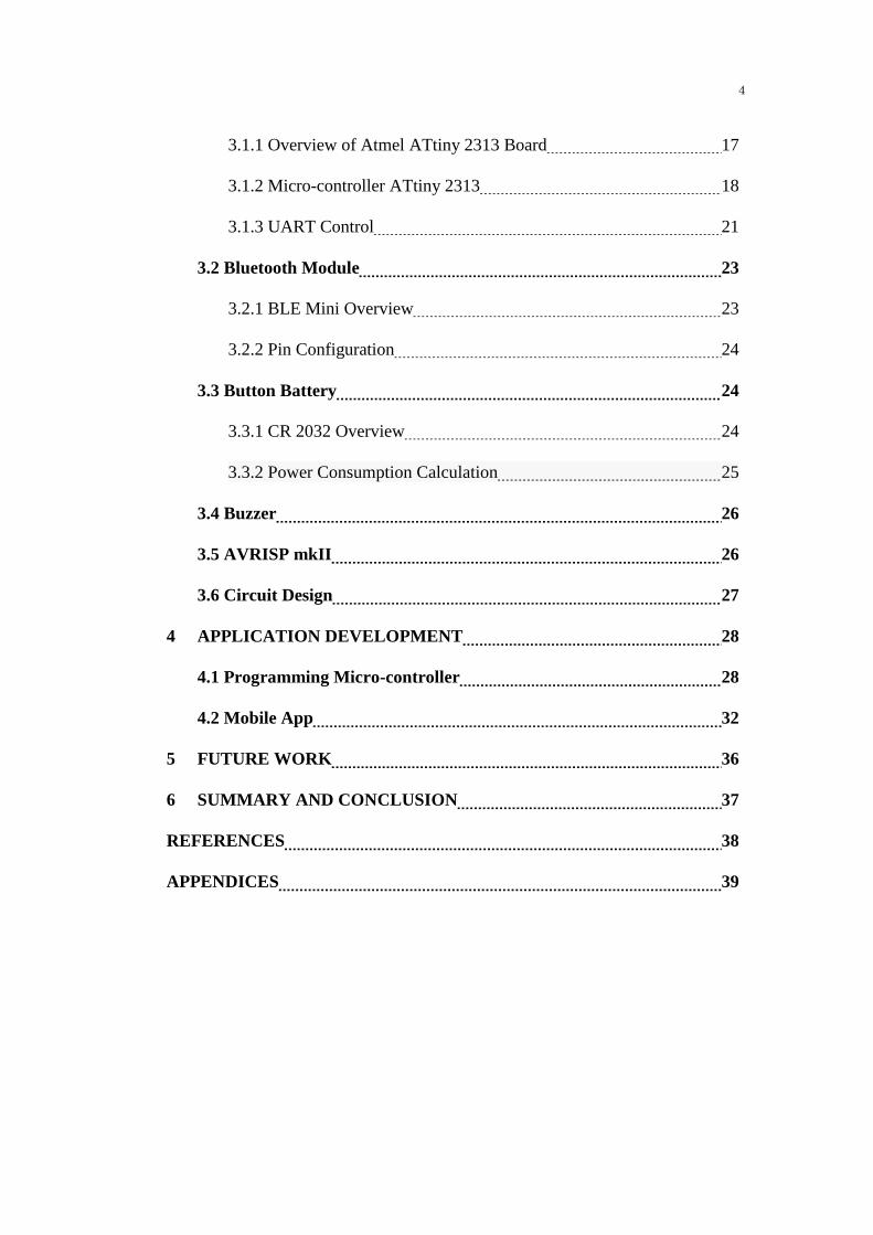
3.4 Buzzer
Figure 3-6: Buzzer
Rated frequency of 4.1KHz
Operating voltage range from 3VDC to 16VD
Maximum current consumption of 7mA at 12VDC
Minimum sound pressure level of 70dB at 30cm/12VDC
Continuous tone
Operating temperature range from -20°C to 70°C
Dimension of 13.7mm x 7.6mm
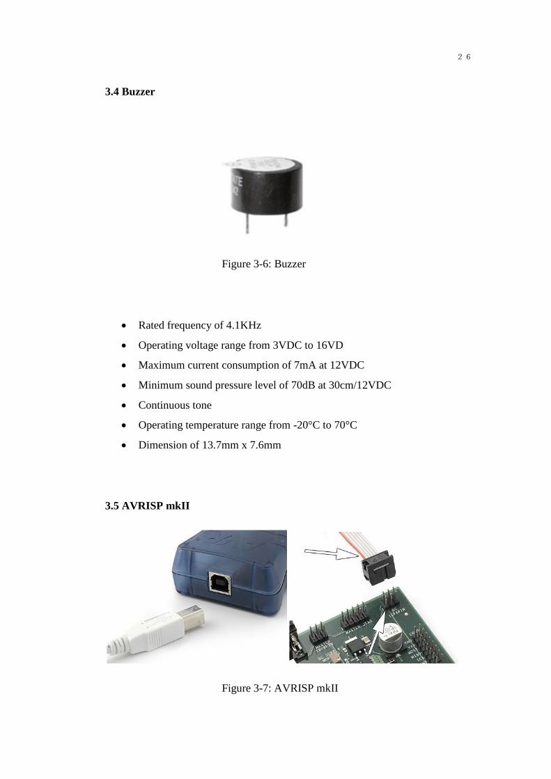
3.5 AVRISP mkII
Figure 3-7: AVRISP mkII

27
The Atmel AVRISP mkII combined with Atmel Studio can program all Atmel
AVR 8-bit RISC microcontrollers with ISP, PDI or TPI Interface
3.6 Circuit Design
Figure 3-8: circuit design
The real PCB board looks like this:

28
Figure 3-9: the key finder
The circuit is designed according to above introduction. The specific PCD design
schematic and layout are in the appendices at the end of the essay.
4 APPLICATION DEVELOPMENT
This Chapter describes how the micro-controller was programmed to control
Bluetooth module, and how to remotely control key finder with mobile App.
4.1 Programming Micro-controller
The software I used was Atmel Studio 6.2. Atmel Studio is released by Atmel
company to program all Atmel AVR micro-controller. It is completely free for
download.
First create a new file.

29
Figure 4-1: Atmel Studio create new file
Secondly choose the micro-controller type.
Figure 4-2: Atmel Studio Setup

30
Setup micro-controller parameters.
Figure 4-3: Atmel Studio setup micro-controller parameters
Thirdly configure Device Programming for debugging.

31
Figure 4-4:Atmel Studio set up Device Programming
Then the micro-controller is ready for programming.
Declare header file, clock frequency and baud rate.
Declare all registers that need to be used.

32
Enable PORTB0 to control buzzer, turned the micro-controller in sleep mode in
the beginning to save power. Then set password to ‘a’, when receiving ‘a’ from
mobile App, the micro-controller will trigger buzzer.
4.2 Mobile App
The mobile used is called BLE Controller which is released by RedBearLab the
same manufacture of Bluetooth module. It can be freely download from Apple
store, Google play and Windows store.

33
Figure 4-5: BLE Controller
Connect to key finder and choose Simple Chat mode.
Figure 4-6: BLE Controller Simple Chat mode
Send password for communication.

34
Figure 4-7: BLE Controller send password to key finder

35
5 FUTURE WORK
In this project, I designed a PCD using micro-controller and Bluetooth module, to
build a remotely wirelessly controlled embedded system. It is a nonchargeable
device.
In the future, this technology can be expanded to other fields. Since it is a small
embedded system, it can be easily used on other IoT (Internet of Things) for
remote controlling. Any collected data can be sent through Bluetooth technology,
Bluetooth technology is very advanced nowadays and really power saving.

36
6 SUMMARY AND CONCLUSION
The key finder is a small PCB board using Bluetooth technology and
micro-controller control. The key components are Bluetooth module and
micro-controller. The AVR micro-controller is a very powerful component, it can
drive many other components. This technology can be expanded to many other
devices.
For the PCB design part, proper pin configuration should be very careful. In order
for the micro-controller to work, a crystal should be added to the circuit. And the
PCB board should be designed as small as possible for easy use.
For the key finder hardware, it is powered by a button battery and nonchargeable.
The micro-controller should be in sleep mode for all the time in the purpose of
power saving. But when password is received by Bluetooth module, the
micro-controller should wake up and trigger the buzzer.
For mobile controlling part, only the owner of the key finder should know the
password. When no password is sent to the key finder, the key finder should
remain silence, it only buzz when receive the right password.

37
REFERENCES
/1/https://www.bluetooth.com/what-is-bluetooth-technology/bluetooth-technology
-basics/low-energy
/2/http://www.atmel.com/products/microcontrollers/avr/tinyavr.aspx
/3/http://www.tietopetri.fi/tuotteet.html
/4/http://www.atmel.com/images/doc2543.pdf
/5/http://homepages.inf.ed.ac.uk/group/sli_archive/slip0304_b/resources/com/karl/
sdp/sdp_intro.html
/6/https://developer.bluetooth.org/TechnologyOverview/Pages/RFCOMM.aspx

38
APPENDICES
Top layer

39
Bottom layer
Source Code
/*
* key finder.c
*
* Created: 18.5.2016 10:21:58
* Author : e1301322
*/
#include <avr/io.h>
#define F_CPU 20000000UL // clock frequency 20 MHz
#include <util/delay.h>
#include <avr/sleep.h>
#include <avr/interrupt.h> // interrupt header

40
#define BAUD_RATE 57600 //bluetooth baud rate
int main(void)
{
DDRB=0x01; // enable pb0 to control buzzer
PORTB=0xff;
UCSRA=0x00;
UCSRB = (1<<RXEN); // enable receiver
UCSRC=0x06; //set fram format: 8data, 2 stop bit
UBRRH = (((F_CPU/BAUD_RATE)/16)-1)>>8; // set baud rate
UBRRL = (((F_CPU/BAUD_RATE)/16)-1); //solve the value loaded into
UBRR register
DDRD &= ~(1 << PD2); // INT0: input...
PORTD |= (1 << PD2); // ...with pullup.
MCUCR &= ~((1 << ISC01) | (1 << ISC00));
GIMSK = (1 << INT0); //INT0: External Interrupt Request 0 Enable
sei();

41
unsigned char ch=0;
while (1)
{
sei();
PORTB=0xff;
GIMSK |= (1 << INT0);
set_sleep_mode(SLEEP_MODE_PWR_DOWN); // set microcontroller
to sleep mode
sleep_mode();
GIMSK &= ~(1 << INT0);
cli();
PORTB=0xFF;
while (!(UCSRA & (1<<RXC)));
ch=UDR; //put data into buffer, sends the data

42
if(ch=='a') //set password as 'a'
{
PORTB=0; // trigger buzzer for 1 second
_delay_ms(1000);
}
}
}
ISR(INT0_vect)
{
}