yuri ismailov ericsson research, stockholm, sweden [email protected] 4 outline introduction...
TRANSCRIPT

Mobility Management in the Internet
Yuri IsmailovEricsson Research, Stockholm , Sweden
11/17/08 [email protected] 2
Objectives
● To get acquainted with issues around networking and m obility
● To understand various approaches providing solutions for m obile networking
● To understand research issues in the area of m obile com m unications
● To inspire research in the area of m obile com m unications

11/17/08 [email protected] 3
Prerequis ites
● Basic knowledge of com puter com m unications
● Basic knowledge of TCP/IP com m unication suite

11/17/08 [email protected] 4
Outline
● Introduction● OSI M odel W alk Through (m obility related features)● M obility M anagem ent M echanism s Overview
– M obile IPv4● M obile IPv4 NAT traversal
– IPv6 Essentials (m obility related focus)
– M obile IPv6
– Identifier – Locator split● Step aside Introducing endpoints
● Level 3 M ulti-hom ing Shim Protocol for IPv6 (SHIM 6)
● Step aside to m ulti-access and IETF M EXT activities
● Host Identity Protocol (HIP)
– Transport Layer Solutions● Focus on “M igrate” and SCTP
– M obile Sockets proposals overview (a word on m obile agents)
– Session Layer Proposal
● Conclusions: Issues, Challenges, W here are we heading to?


11/17/08 [email protected] 6
What is Mobility?
● There is no strict definition of m obility
● RFC 3344 “M obility Support for IPv4” and RFC 3775 “M obility Support in IPv6” m ention the following:
– Packets m ay be routed to the m obile node using this address (Hom e Address) regardless of the m obile node's current point of attachm ent to the Internet
– For a node to change its point of attachm ent without losing its ability to com m unicate ...
Mobile device changes its point of attachment to the network

11/17/08 [email protected] 7
Examples of What May be Mobile
Application
TCPIP
Link LinkInterfaceInterface
Socket

11/17/08 [email protected] 8
Vis ion
● M obility is when som ething changes with regard to networked objects
● M obility support is:
– If m obile resource of any type changes its point of attachm ent, context, preferences, policies, and anything else, what can be change – this, results in adequate system reaction providing continuous reachability and com m unication continuity

11/17/08 [email protected] 9
Key Is sues Influencing Mobility S upport● Nam ing and addressing – what to nam e and how (both syntax and sem antics). How to resolve nam es and what should be the result of nam e resolution.
● Dynam ic bindings – which part of the nam e is static and which can change (Locater – Identifier Split). How to keep consistency.
● State m anagem ent – which state (part) inform ation has to be preserved across a handover, tem porarily disconnections, network outages, deliberate com m unication suspend/resum e actions, etc.
● Utilization of inform ation at all layers (sub-layers) of the stack – useful for optim izations and proper control of dynam ic bindings
● Interaction with applications – revealing data from the stack to applications letting them to have som e control over this data, and notifying applications about critical events taking place inside the stack
● Protocol support for consistent updates of involved in m obility support nodes


11/17/08 [email protected] 11
Naming and Address ing: What to Name?
S tatic/Pers is tent Name vs . Dynamic/Changeable
http://
ServiceName
Static
www.com puter.com
ComputerName
Dynamic
/what/ever/directory/
Directory PathName
Dynamic
file.htm l
FileName
Dynamic
Dynamic
Mapped toPort Number
Mapped toIP Address
Static
Think of two issues:1. Naming and Addressing2. Dynamic Bindings

11/17/08 [email protected] 12
Naming and Address ing: Decoupling of Objects
● Decoupling of networked objects leads to:
– Need of persistent nam e for each “m ovable” object
– Need of capability to dynam ically rebind persistent nam e to any other nam e with the life-tim e shorter than the persistent nam e of the object

11/17/08 [email protected] 13
Dynamic Bundling of Names
Layer N1
Layer N-11
Layer N+11
Layer Z1
Layer 11
...
...
Layer N2
Layer N-12
Layer N+12
Layer Z2
Layer 12
...
...
Layer NN
Layer N-1N
Layer N+1N
Layer ZN
Layer 1N
...
...
...
...
...
...
...
Layer N
Layer N-1
Layer N+1
Layer Z
Layer 1
...
...
... ... ...
Layer N
Layer N-1
Layer N+1
Layer Z
Layer 1
...
Layer N
Layer N-1
Layer N+1
Layer Z
Layer 1
...
Layer N
Layer N-1
Layer N+1
Layer Z
Layer 1
...

11/17/08 [email protected] 14
Example of S tate Preservation and Transfer
Network
Session Establishment(authentication and session state setup) Hello, it's me, Bob
Hi, how are you doing
Communication(state update) Bla1, Bla2, Bla3, ...., Bla1372
Oj1, oj2, oj3, ...., oj1973
Bla1373, Bla1374, Bla1375, ....Oj1974, oj1975, oj1976, ....
Communication Continued(state update)
Communication Interruption (Preserve/Save and Possibly Transfer current state) Suspend Phase
Communication restored(re-authentication) Hi, its me again

11/17/08 [email protected] 15
S tate Management
● Question: W hich networked object do we m ean and what com prises its state?
– M oving a device with one interface
– M oving one interface on a device with m ultiple interfaces
– M oving an application
– M oving a content
– M oving a user between devices

11/17/08 [email protected] 16
Utilization of Information at All Layers
● Im portant for various optim izations during a handover
– A handover is going to be perform ed to an interface with poorer characteristics. TCP tim ers can be handled accordingly
– TCP experiences packet loss right after handover. There is no need to trigger “standard” TCP recovery m echanism s. Retransm issions can be triggered im m ediately, due to the known reason of packet loss
– Assum e an application has knowledge about available interfaces and decides to m ove its flow(s) between them . TCP can be instructed about adequate behavior
– Any other ideas?

11/17/08 [email protected] 17
Interaction with Applications
● Notifications to applications from the stack can lead to various perform ance optim izations, for exam ple:
– If system prepares to perform handover, an application can use it as “stop sending data” instruction in order to reduce num ber of lost packets during handover
– If TCP socket is going to be closed due to the tim e-out, an application can use it as “do not panic, preserve state” instruction
– Assum e there is a system support for re-opening of a socket after tim e-out, then an application can use it as “restore state and continue the session” instruction.
– Any other ideas?

11/17/08 [email protected] 18
Protocol S upport
● How to keep consistency after changes have taken place?
– IP address change
– Port num ber change
– Interface characteristics change
– Service m ove (decoupling of service and content)
– Content m ove
– User m ove


Open S ystems and Open S ystems Interconnection
11/17/08 [email protected] 21
Open S ystems: OS I Definition
● The term Open System s Interconnection (OSI) qualifies standards for the exchange of inform ation am ong system s that are "open" to one another for this purpose by virtue of their m utual use of the applicable standards.***
*** Information Technology Open Systems Interconnection – Basic Reference Model: The Basic Model. iso_iec_7498-1.txt

11/17/08 [email protected] 22
Open Communication S ystems – Des ign Approach
● Layered architecture● Definition of functions for each layer (service definition)● Definition of interconnection rules between layers (addressing, m ultiplexing)
● Definition of protocol(s) for each layer

11/17/08 [email protected] 23
Open S ystems: OS I Layers
Layer 1(physical)
Layer N
...
Layer 7(application)
Layer N
Service to layer N+1
Service to layer N-1
Protocol with peer layer N
Addressing(service access point)
...
● Naming & Address ing– Scope
– Sem antic
– Lifetim e
– Independence
– Bundling policy
● S ervice Definition– Functional definition of what services
are provided
● Protocol specification– Form at of PDU
– Sem antics of fields
– Allowable sequence of PDU

11/17/08 [email protected] 24
Open S ystems: PDU Formation
L6 HeaderL N-1 Header …
Application Payload
…LN Header
L 2 Header ……
Layer 1(physical)
Layer N
...
Layer 7(application)
...
Application Payload
Application Payload
Application Payload
L6 Header
L6 Header
L N-1 Header
L N-1 Header
LN Header

11/17/08 [email protected] 25
Open S ystems: S ub-layering
Layer N-1
……
Layer N
Layer N (Sub-Layer)Layer N (Sub-Layer)
Layer N (Sub-Layer)
Layer N+1
Minimal set of functions introduced to adjacent layers
Layer service is the service, which can not be bypassed.
Sub-layer service m ay be bypassed and m ay not be m andatory for im plem entation
Layer N (Sub-Layer)Layer N (Sub-Layer)
Layer N (Sub-Layer)

11/17/08 [email protected] 26
Invocation of a S ublayer Functions
● Questions with regard to introduction of sub-layers
– W hat is used to identify flows / packets?
– How to provide an oder of sub-layers functions execution?
– How to provide an order of sub-layers functions execution per application / per flow?
– How to provide a different subset of sub-layers functions per application / per flow?
– How to change a set of sub-layer functions during run-tim e, i.e. for active flows?
– How to apply proper subset of sub-layers functions to incom ing packets
– IP sub-layers: what is the role of traditional routing table?

11/17/08 [email protected] 27
Invocation of a S ublayer Functions
App
Layer N+1
...
Layer 1
Layer N
F+1(N)
F+2(N)
F+K(N)...
Basic Service at Layer N
F-1(N)
F-2(N)
F-K(N)...
Ordering FunctionO rder
M anagem entFunction
Order Control(Who is the Manager? )Central (per device)?Per Application?
Per Flow?
Layer N-1...

11/17/08 [email protected] 28
Invocation of S ublayer Functions
App1
Layer N+1
...
Layer N-1
Layer 1
...
Layer N
Basic Service at Layer N
F-1(N)
F-2(N)
F-K(N)
...
F+1(N)
F+2(N)
F+K(N)
...
App2
● Each application creates a dedicated ordering function
● An order of sub-layers invocation at each layer is specified at the creation tim e of dedicated ordering function
● For generic m obility purposes change of sub-layers functions and their order should be supported

11/17/08 [email protected] 29
TCP/IP S tack: Invocation of S ub-Layers (1)
● XFRM (Transform er) is a network program m ing fram ework included in Linux since kernel version 2.5
– The idea is to be able to m odify the path of packets through the networking stack based on som e policies. The fram ework, originally designed to im plem ent IPsec, has later been used for the M obile IPv6 im plem entation [1]
– Later on suggested to use the XFRM fram ework as a base for SHIM 6 im plem entation [2]
[1] “IPv6 IPsec and M obile IPv6 im plem entation of Linux”. Kazunori M IYAZAW A,
M asahide NAKAM URA. Proceedings of the Linux Sym posium , Volum e Two, July 21th–24th, 2004, O ttawa, O ntario, Canada
[2] “Im plem enting SHIM 6 Using the Linux XFRM Fram ework”. S bastien Barr , Olivier é é
Bonaventure. Routing in Next G eneration W orkshop, M adrid (Spain) - 13-14 Decem ber 2007.

11/17/08 [email protected] 30
● XFRM packet process ing is based on the policies database (RFC 4301 allows multiple policies databases)
– A policy is m ade of a selector[1], a direction, an action and a tem plate
– The policy is applied to a packet if it m atches the selector and is flowing in the direction of that policy (inbound or outbound)
– The selector m echanism allows one to use the addresses, ports, address fam ily and protocol num ber as fields for the m atching
– If a packet m atches a given policy. In that case the tem plate is used to get a description of the transform ations needed for that kind of packet, and leads to an action to be applied for the packet
TCP/IP S tack: Invocation of S ub-Layers (2)
[1] “Security Architecture for IP”. S. Kent, K. Seo. IETF RFC 4301

11/17/08 [email protected] 31
xfrm_templ
TCP/IP S tack: Invocation of S ub-Layers
ipv6_route_output
xfrm_lookup
xfrm_templ_resolve
xfrm_bundle_create
sk_buf
xfrm_policy
xfrm_templxfrm_templ
xfrm_templxfrm_templxfrm_state
original_dst
sk_buf dst
dst
original_dst
XXX_output
XXX_output
XXX_output

11/17/08 [email protected] 32
TCP/IP S tack: Invocation of S ub-Layers (3)
ipv6_route_output
xfrm_lookup
xfrm_templ_resolve
xfrm_bundle_create
sk_buf
xfrm_policylxfrm_templ
xfrm_state
original_dst
dst XXX_output
xfrm_policylxfrm_templ
xfrm_state
sk_buf
dst XXX_output
dst XXX_output
dst XXX_output
dst XXX_output
original_dst XXX_output

11/17/08 [email protected] 33
Open S ystems: Multiplexing
● M ultiplexing / De-m ultiplexing is an im portant design feature of layered architecture.
● M ultiplexing applicable at any layer.● Upward m ultiplexing● Downward m ultiplexing

11/17/08 [email protected] 34
Open S ystems: Multiplexing
Layer N
Layer N+1
Layer N-1
Layer N
Layer N-1 Layer N-1
Layer N
Layer N
Layer N+1 Layer N+1
M ultiplexing based on SAP diversity at a single layer M ultiplexing based on functional layer diversity

11/17/08 [email protected] 35
Invocation of Layers at Each Level
Application
Layer N+11
...
Layer 1
Layer N-11
...
Layer N1
Layer N+12
Layer N2
Layer N-12
...
...
Layer 1
● Questions:
– W hat is the m echanism of invoking different layers at each level in the current TCP/IP downwards?
– W hat is the m echanism of invoking different layers at each level in the current TCP/IP upwards?

11/17/08 [email protected] 36
Open S ystems: Multiplexing
● Downwards
– Shared by the set of layers structure filled in by a creator of the whole or partial path.
– A m ultiplexing m echanism im plem ented at a separate layer – need for unam biguous solution.
● Upwards – Fields in protocol header describing
the upper layer receiver protocol and its SAP nam e.
– These fields allow to provide unam biguous m apping of PDU to correspondent shared structure in order to reach appropriate end-point.
– If m ultiplexing done based on SAP diversity then only field with SAP nam e is enough.
– If m ultiplexing based on protocol diversity then only next protocol field enough.
– In the m ost generic case both fields should be present

11/17/08 [email protected] 37
TCP/IP Protocol S tack: Mapping onto OS I S AP
Ether WLAN PPP …
IPv4IPv6
TCP UDP
Application
SAP Port Num bers1 64K
SAP
IP AddressesV6 (0 - 2128 – 1)V4 (0 - 232 – 1)
SAP Interface Nam eeth0, ppp1, sl2, …
HTTP, SM TP, PO P, FTP, TELNET, VIDEO/AUDIO STREAM ING, ICQ, …
WAN

11/17/08 [email protected] 38
TCP/IP Protocol S tack: Mapping onto OS I Multiplexing
Ether WLAN PPP …
IPv4IPv6
UDP
Application
TCP
Downwards Upwards
Transport ServicePort Num berProtocol Fam ily
Socket Structure
eth0, eth1, ppp2, sl1
Routing Table
WAN
Next Protocol
Next Protocol
Port Num ber
No Next Protocol???
11/17/08 [email protected] 39
Internet Architecture Highlights
● Fixed infrastructure (topology)● IP address distribution is done in centralized way and they (IP addresses) belong to infrastructure.
● Nam e resolution is a centrally m anaged function● Topological correctness of IP addresses is the key for correct functioning of IP routing.

11/17/08 [email protected] 40
References
● W illiam Stallings. “Data and Com puter Com m unications”, 5th edition, ISBN 0-13-571274-2. (Chapter 15)
● Douglas E. Com er. “Com puter Networks and Internets”, ISBN 0-13-239070-1. (Chapters 10, 12)
● ISO Standard. “Inform ation Processing System s - OSI Reference M odel - The Basic M odel “. http://www.acm .org/sigcom m /standards/iso_stds/OSI_M O DEL/ISO_IEC_7498-1.TXT
● ISO Standard. “Open System s Interconnection - Basic Reference M odel: Nam ing and Addressing”. http://www.acm .org/sigcom m /standards/iso_stds/OSI_M O DEL/ISO_IEC_7498-3.TXT


Mobility Management S olutions(Impact on the TCP/IP s tack)

11/17/08 [email protected] 43
Mobility Management S olutions S pace
● Below Transport Layer Solutions
– M obile IPv4
– IPv6 Essentials
– M obile IPv6
– Proxy M obile IPv6
– Shim 6
– M obile IPv6 + M EXT (M obile EXTensions)


11/17/08 [email protected] 45
Mobile IPv4 (MIPV4)
● M otivation– The node m ust change its IP address whenever it changes its point of attachm ent, or
– host-specific routes m ust be propagated throughout m uch of the Internet routing fabric.
● Both of these alternatives are often unacceptable. The first m akes it im possible for a node to m aintain transport and higher-layer connections when the node changes location. The second has obvious and severe scaling problem s

11/17/08 [email protected] 46
MIPv4: Approach
● Approach (RFC 3344)– “A new, scalable, m echanism is required for accom m odating node m obility within the Internet. This docum ent defines such a m echanism , which enables nodes to change their point of attachm ent to the Internet without changing their IP address.”

11/17/08 [email protected] 47
MIPv4: New Architectural Entities
● M obile Node– A host or router that changes its point of attachm ent from one network or sub-network to another. A m obile node m ay change its location without changing its IP address; it m ay continue to com m unicate with other Internet nodes at any location using its (constant) IP address, assum ing link-layer connectivity to a point of attachm ent is available.
● Hom e Agent– A router on a m obile node's hom e network which tunnels datagram s for delivery to the m obile node when it is away from hom e, and m aintains current location inform ation for the m obile node.
● Foreign Agent– A router on a m obile node's visited network which provides routing services to the m obile node while registered. The foreign agent de-tunnels and delivers datagram s to the m obile node that were tunneled by the m obile node's hom e agent. For datagram s sent by a m obile node, the foreign agent m ay serve as a default router for registered m obile nodes.

11/17/08 [email protected] 48
MIPv4: IP Addresses Ass igned to a Mobile Node
● Hom e IP Address– Long term assignm ent.– Topologically belongs to the hom e network.– Can be statically m apped to FQ DN and resolved through DNS.
● Care-of-Address (CoA)– Short term assignm ent– Topologically belongs to the visited network– Two types of Care-of-Addresses:
● Foreign Agent Care-of-Address● Collocated Care-of-Address

11/17/08 [email protected] 49
MIPv4: Operation with Foreign Agent
CN
HA
MN
1
Datagram is intercepted by home agent and is tunneled to the care-of address.
FA
For datagrams sent by the mobile node, standard IP routing delivers each to its destination.
Datagram is de-tunneled and delivered to the mobile node.
Datagram to mobile node arrives on home network via standard IP routing
2 3
4
11/17/08 [email protected] 50
MIPv4: Operation with Collocated CoA
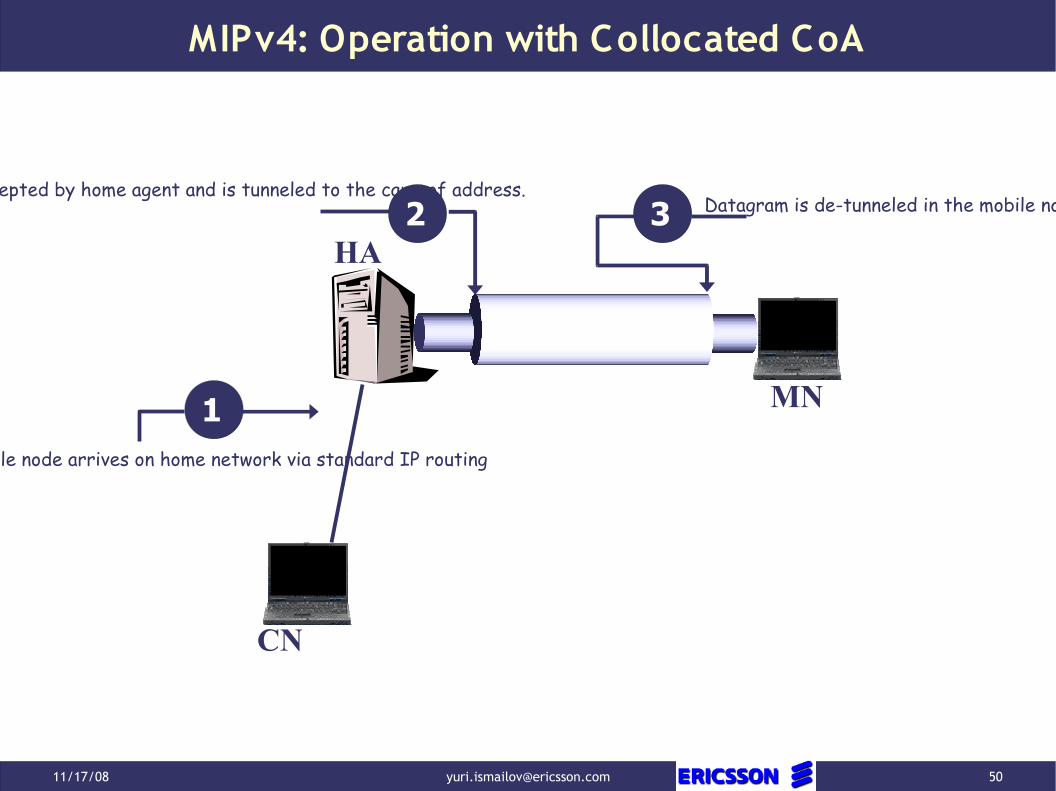
CN
HA
MN1
Datagram is intercepted by home agent and is tunneled to the care-of address.
Datagram to mobile node arrives on home network via standard IP routing
2 3 Datagram is de-tunneled in the mobile node.

11/17/08 [email protected] 51
MIPv4: Operation Procedures
● Agent Discovery● Agent Advertisem ent● Agent Solicitation● M ovem ent Detection● Registration● Tunneling
11/17/08 [email protected] 52
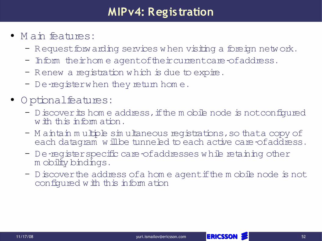
MIPv4: Regis tration
● M ain features:– Request forwarding services when visiting a foreign network.– Inform their hom e agent of their current care-of address.– Renew a registration which is due to expire.– De-register when they return hom e.
● Optional features:– Discover its hom e address, if the m obile node is not configured with this inform ation.
– M aintain m ultiple sim ultaneous registrations, so that a copy of each datagram will be tunneled to each active care-of address.
– De-register specific care-of addresses while retaining other m obility bindings.
– Discover the address of a hom e agent if the m obile node is not configured with this inform ation

11/17/08 [email protected] 53
MIPv4: Layered Model View
● According to PDU Form ation and RFC 2003 “IP Encapsulation within IP” one can conclude that M IPv4 is the layer below IP layer.
PDU Form ation:
SAP Nam es and M ultiplexing:
Outer IP Header IP Header IP Payload
● Use of the sam e SAP nam es syntax and sem antics as above● Lifetim e of nam es at M IP4 layer is longer● Bundling policy of nam es is different from IP layer
11/17/08 [email protected] 54
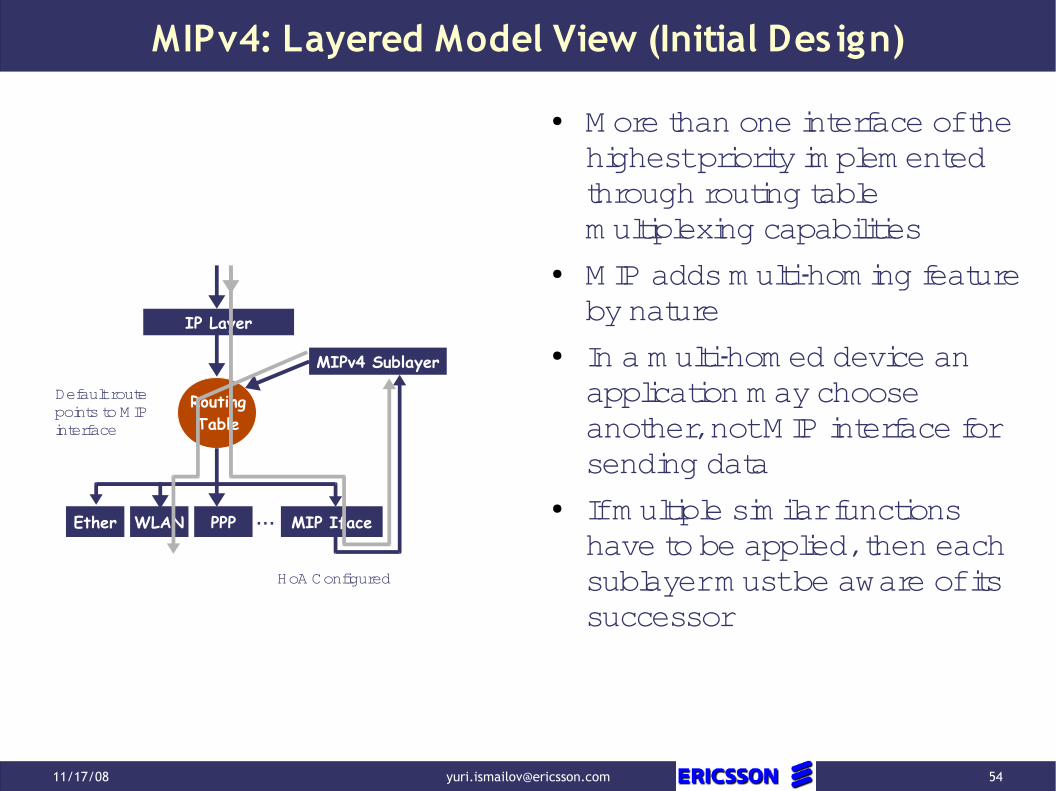
MIPv4: Layered Model View (Initial Des ign)
RoutingTable
MIPv4 Sublayer
Ether …WLAN PPP MIP Iface
IP Layer
HoA Configured
Default route points to M IP interface
● M ore than one interface of the highest priority im plem ented through routing table m ultiplexing capabilities
● M IP adds m ulti-hom ing feature by nature
● In a m ulti-hom ed device an application m ay choose another, not M IP interface for sending data
● If m ultiple sim ilar functions have to be applied, then each sublayer m ust be aware of its successor

11/17/08 [email protected] 55
MIPv4: Layered Model View (Currently Poss ible Des ign)
Ether …WLAN PPP MIP Iface
RoutingTable
Default route points to M IP interface
HoA Configured
IP Layer
MIPv4 Sublayer
XFRM
Packet Inspection
● M uch cleaner design
● Tolerates application of m ultiple functions due to the introduction of policies controlled function ordering
● Routing table has to be queried once, which has cleaner nam es sem antics
● M ay lead to am biguity if m ore than one function requires default applications binding

11/17/08 [email protected] 56
MIPv4: NAT Traversal
● NAT allows outgoing traffic, which m akes registration possible using IP in UDP encapsulation
● UDP well known port 434● Reverse tunneling should be used because there is no requirem ent on CN to im plem ent M IP
● Keep alive interval is set preventing outer NAT UDP port to tim eout
Outer IP Header UDP Header MIP Ext Header IP Header IP Payload
PDU Format:

11/17/08 [email protected] 57
MIPv4: NAT Traversal (S tack Projection)
Outer IP Header UDP Header MIP Ext Header IP Header IP Payload
Interface
RoutingTable
M ultiplexing on assigned num bers for the next protocol field
IP Layer
UDPNext Protocol = 17
MIPv4 User Space
Next Protocol = 4
Port Number = 434
TCP
Application
?
MIPv4 Sublayer

11/17/08 [email protected] 58
MIPv4: NAT Traversal (S ess ion Continuity)
HA IP, MN CoA HA-434, MN-Port MIP Ext Header CN IP, MN HoA IP Payload
HA IP, NAT IP HA-434, NAT-Port MIP Ext Header CN IP, MN HoA IP Payload
MN CN
PrivateIPv4
PublicIPv4
PublicIPv4
HANAT
HA IP, MN CoA CN IP, MN HoA IP Payload
Topic 2

11/17/08 [email protected] 59
MIPv4: NAT Traversal (S ess ion Continuity)
Interface
RoutingTable
IP Layer
UDP
MIPv4 User Space
TCP
Application
?
MIPv4 Sublayer
● The m ove from behind a NAT has to be recognized
● Looks like that there will be no im pact on inbound traffic
● Outbound traffic processing has to be changed
● Using XFRM fram ework m eans changing of policies

11/17/08 [email protected] 60
MIPv4: References
● C. Perkins, Ed. “IP M obility Support for IPv4”, IETF RFC 3344, August 2002, http://www.ietf.org/rfc/rfc3344.txt
● J. Solom on. “Applicability Statem ent for IP M obility Support”, IETF RFC 2005, October 1996, http://www.ietf.org/rfc/rfc2005.txt
● G. M ontenegro, Editor. “Reverse Tunneling for M obile IP, revised”, IETF RFC 3024, January 2001, http://www.ietf.org/rfc/rfc3024.txt
● H. Levkowetz, S. Vaarala. “M obile IP Traversal of Network Address Translation (NAT) Devices”, IETF RFC 3519, April 2003, http://www.ietf.org/rfc/rfc3519.txt
● P. Calhoun, C. Perkins. “M obile IP Network Access Identifier Extension for IPv4”, IETF RFC 2794, M arch 2000, http://www.ietf.org/rfc/rfc2794.txt


11/17/08 [email protected] 62
IPv6 Essentials
● Expanded Addressing Capabilities● Header Form at Sim plification
– Som e IPv4 header fields have been dropped or m ade optional, to reduce the com m on-case processing cost of packet handling and to lim it the bandwidth cost of the IPv6 header
● Im proved Support for Extensions and Options● Flow Labeling Capability● Authentication and Privacy Capabilities
11/17/08 [email protected] 63
IPv6 Essentials : Header Format
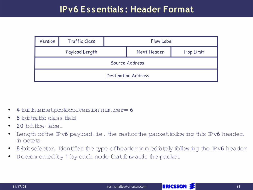
● 4-bit Internet protocol version num ber = 6● 8-bit traffic class field● 20-bit flow label● Length of the IPv6 payload, i.e., the rest of the packet following this IPv6 header,
in octets.● 8-bit selector. Identifies the type of header im m ediately following the IPv6 header● Decrem ented by 1 by each node that forwards the packet
Version Traffic Class Flow Label
Payload Length Next Header Hop Limit
Source Address
Destination Address

11/17/08 [email protected] 64
IPv6 Essentials
● Expanded Addressing Capabilities● Header Form at Sim plification● Im proved Support for Extensions and Options● Flow Labeling Capability● Authentication and Privacy Capabilities

11/17/08 [email protected] 65
IPv6 Essentials : Extens ions and Options
● A full im plem entation of IPv6 includes im plem entation of the following extension headers:– Hop-by-Hop Options– Destination O ptions– Routing– Fragm ent– Authentication (not defined by RFC 2460)– Encapsulating Security Payload (not defined by RFC 2460)
● Im portant! Each extension header should occur at m ost once

11/17/08 [email protected] 66
IPv6 Essentials : Routing Extens ion Header
● Next Header identifies the type of header im m ediately following the Routing header
● Header Ext Len is the length of the routing header in 8-octet units not including the first 8 octets
● Segm ents Left is the num ber of explicitly listed interm ediate nodes still to be visited before reaching the final destination
Next Header Header Ext Len Routing Type=0
Reserved
Address[1]
Segments Left
Address[2]
Address[n]
…


11/17/08 [email protected] 68
IPv6: Routing Header S tack View
Next Header Header Ext Len Routing Type=0
Reserved
Address[1]
Segments Left
Address[2]
Address[n]
…
Assum e that in the place of addresses we will specify the sam e address and it will be a destination address, then the packet will traverse the stack in the following way
Interface
RoutingTable
IP Layer
Does this rem ind som ething?

11/17/08 [email protected] 69
IPv6: Routing Header Deprecation
● The severity of this threat is considered to be sufficient to warrant deprecation of RH0 entirely. A side effect is that this also elim inates benign RH0 use-cases; however, such applications m ay be facilitated by future Routing Header specifications.
● An IPv6 node that receives a packet with a destination address assigned to it and that contains an RH0 extension header M UST NOT execute the algorithm specified in the latter part of Section 4.4 of [RFC2460] for RH0.
● Instead, such packets M UST be processed according to the behavior specified in Section 4.4 of [RFC2460] for a datagram that includes an unrecognized Routing Type value
RFC 5095 “Deprecation of Type 0 Routing Headers in IPv6”
11/17/08 [email protected] 70
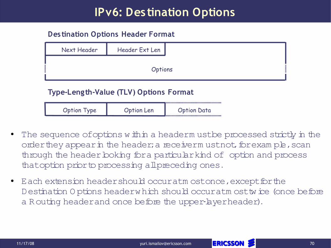
IPv6: Destination Options
Next Header Header Ext Len
Options
Option Type Option Len Option Data
Type-Length-Value (TLV) Options Format
Destination Options Header Format
● The sequence of options within a header m ust be processed strictly in the order they appear in the header; a receiver m ust not, for exam ple, scan through the header looking for a particular kind of option and process that option prior to processing all preceding ones.
● Each extension header should occur at m ost once, except for the Destination Options header which should occur at m ost twice (once before a Routing header and once before the upper-layer header).
11/17/08 [email protected] 71
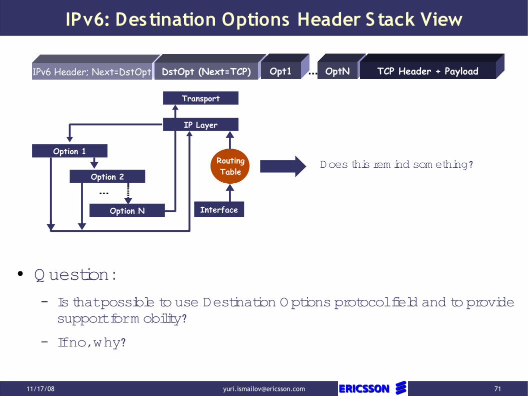
IPv6: Destination Options Header S tack View
IPv6 Header; Next=DstOpt DstOpt (Next=TCP) Opt1 OptN... TCP Header + Payload
Does this rem ind som ething?
Interface
RoutingTable
IP Layer
Option 1
Option 2
Option N
...
Transport
● Question:
– Is that possible to use Destination Options protocol field and to provide support for m obility?
– If no, why?

11/17/08 [email protected] 72
IPv6: References
● S. Deering, R. Hinden. “Internet Protocol, Version 6 (IPv6) Specification”, IETF RFC 2460, Decem ber 1998
● J. Abley, P. Savola, G. Neville-Neil. “Deprecation of Type 0 Routing Headers in IPv6”, IETF RFC 5095, Decem ber 2007
● R. Draves. “Default Address Selection for Internet Protocol version 6 (Ipv6)”. IETF RFC 3484, February 2003


11/17/08 [email protected] 75
MIPv6: Differences to MIPv4
● There is no need to deploy special routers as "foreign agents", as in M obile IPv4. M obile IPv6 operates in any location without any special support required from the local router.
● Support for route optim ization is a fundam ental part of the protocol, rather than a nonstandard set of extensions.
● M obile IPv6 route optim ization can operate securely even without pre-arranged security associations. It is expected that route optim ization can be deployed on a global scale between all m obile nodes and correspondent nodes.
● Support is also integrated into M obile IPv6 for allowing route optim ization to coexist efficiently with routers that perform "ingress filtering"
● The IPv6 Neighbor Unreachability Detection assures sym m etric reachability between the m obile node and its default router in the current location.
● M ost packets sent to a m obile node while away from hom e in M obile IPv6 are sent using an IPv6 routing header rather than IP encapsulation, reducing the am ount of resulting overhead com pared to M obile IPv4.
● M obile IPv6 is decoupled from any particular link layer, as it uses IPv6 Neighbor Discovery [12] instead of ARP. This also im proves the robustness of the protocol.
● The use of IPv6 encapsulation (and the routing header) rem oves the need in M obile IPv6 to m anage "tunnel soft state".
● The dynam ic hom e agent address discovery m echanism in M obile IPv6 returns a single reply to the m obile node. The directed broadcast approach used in IPv4 returns separate replies from each hom e agent.

11/17/08 [email protected] 76
MIPv6: B idirectional Tunneling Mode
● Bidirectional tunneling does not require M obile IPv6 support from the correspondent node and is available even if the m obile node has not registered its current binding with the correspondent node.
CN
HA
MN1
Datagram is intercepted by home agent and is tunneled to the care-of address.
Datagram to mobile node arrives on home network via standard IP routing
2 3 Datagram is de-tunneled in the mobile node.
Outer IP Header IP Header IP Payload
IP Header IP Payload

11/17/08 [email protected] 77
MIPv6: Route Optimization Mode
● "Route Optim ization" m ode requires the m obile node to register its current binding at the correspondent node. Packets from the correspondent node can be routed directly to the care-of address of the m obile node. W hen sending a packet to any Ipv6 destination, the correspondent node checks its cached bindings for an entry for the packet's destination address. If a cached binding for this destination address is found, the node uses a new type of IPv6 routing header to route the packet to the m obile node by way of the care-of address indicated in this binding

11/17/08 [email protected] 78
MIPv6: Route Optimization Mode
● New Type of Routing Header
● New IPv6 "Hom e Address" destination option to carry its hom e address. The inclusion of hom e addresses in these packets m akes the use of the care-of address transparent above the network layer
● M obile IPv6 defines a new IPv6 protocol, using the M obility Header. This Header is used to carry the following m essages:
– Hom e Test Init
– Hom e Test
– Care-of Test Init
– Care-of Test
● These four m essages are used to perform the return routability procedure from the m obile node to a correspondent node. This ensures authorization of subsequent Binding Updates

11/17/08 [email protected] 79
MIPv6: Routing Header (Type 2)
● Once the packet arrives at the care-of address, the m obile node retrieves its hom e address from the routing header, and this is used as the final destination address for the packet
Next Header Header Len
Home Address
Routing Header (Type 2) Format
MH Type Segments Left
Reserved
Interface
RoutingTable
IP Layer
Routing based on CoA
Routing based on HoA

11/17/08 [email protected] 80
MIPv6: HoA Destination Option
● It is used in a packet sent by a m obile node while away from hom e, to inform the recipient of the m obile node's hom e address
● Standard TLV form at within the destination options header
● For each IPv6 packet header, the Hom e Address Option M UST NOT appear m ore than once
● The Hom e Address option M UST be placed as follows:
– After the routing header, if that header is present
– Before the Fragm ent Header, if that header is present
Option Type Option Len Home Address
HoA Destination Option Form at

11/17/08 [email protected] 81
MIPv6 Mobility Header
Ipv6 Header Mobility IP Header IP Payload
Next HeaderHeader Len
Message Data
Mobility Header Format
(Payload Protocol) MH Type Reserved
Checksum
MN
HA
CN
HoTIHoTI
CoTI
1
11
HoT
2
CoT2
BU3

11/17/08 [email protected] 82
MIPv6: Why S ecure BU in RO Mode
● The BU orders the receiver to send traffic to a different IP address (e.g. packets intended for address X should be sent to Y)
● Attackers can:
– Direct a M N’s traffic to them selves (steal traffic)
– Direct a M N’s traffic som ewhere else (Bom bing attacks)
– Deny a M N from com m unicating with other nodes (DoS attacks).
– M ore attacks are possible.

11/17/08 [email protected] 83
MIPv6: Control and Data Messages
Ipv6 Header Mobility IP Header IP Payload
● Signaling m essages for Return Routability Procedure, Binding Updates, etc.
● Data M essages from M obile
Ipv6 Header DstOpt (HoA) IP Payload
● Data M essages to M obile
Ipv6 Header Routing Header (2) IP Payload

11/17/08 [email protected] 84
MIPv6: References
● D. Johnson, C. Perkins, J. Arkko “M obility Support in Ipv6”. IETF RFC3775, June 2004
● A. Patel, K. Leung, M . Khalil, H. Akhtar, K. Chowdhury “M obile Node Identifier Option for M obile IPv6 (M IPv6)”. IETF RFC 4283, Novem ber 2005


11/17/08 [email protected] 86
Client vs . Network Initiated Handover
● M IPv6 and M IPv4 are typical exam ples of client initiated handover
– A client has to detect m ovem ent
– A client starts procedure to ensure delivery of subsequent packets to a new Care-of-Address
– This is also called Break-Before-M ake (BBM )
● Exam ple of network Initiated handover is traditional Telecom network
– A client reports signal strength and visible RBS up to the network
– The network through Radio Resource M anagem ent support using sophisticated algorithm s decides which RBS the client has to be connected to
– The network sends com m ands to the client to perform handover
– This is also called M ake-Before-Break (M BB)
M IPv4 & M IPv6 can perform M BB as well if a client is capable of m aintaining sim ultaneous connectivity to both networks

11/17/08 [email protected] 87
Global vs Local Mobility S upport
● Local M obility
– Local M obility is m obility over an access network. Note that although the area of network topology over which the m obile node m oves m ay be restricted, the actual geographic area could be quite large, depending on the m apping between the network topology and the wireless coverage area
● Localized M obility M anagem ent
– Localized M obility M anagem ent is a generic term for any protocol that m aintains the IP connectivity and reachability of a m obile node for purposes of m aintaining session continuity when the m obile node m oves, and whose signaling is confined to an access network

11/17/08 [email protected] 88
Global vs Local Mobility S upport: S cope
Access NetworkGateway
Access Router Access Router
AccessPoint
AccessPoint
AccessPoint
Access Router
AccessPoint
AccessPoint
Access NetworkGateway
Intra-link(Layer2)M obility
LocalM obility
G lobalM obility

11/17/08 [email protected] 89
Local Mobility: Problem S tatement● Update latency. If the global m obility anchor point and/or correspondent node (for
route-optim ized traffic) is at som e distance from the m obile node's access network, the global m obility update m ay require a considerable am ount of tim e. During this tim e, packets continue to be routed to the old tem porary local address and are essentially dropped
● Signaling overhead. The am ount of signaling required when a m obile node m oves from one last-hop link to another can be quite extensive, including all the signaling required to configure an IP address on the new link and global m obility protocol signaling back into the network for changing the perm anent to tem porary local address m apping. The signaling volum e m ay negatively im pact wireless bandwidth usage and real-tim e service perform ance.
● Location privacy. The change in tem porary local address as the m obile node m oves exposes the m obile node's topological location to correspondents and potentially to eavesdroppers. An attacker that can assem ble a m apping between subnet prefixes in the m obile node's access network and geographical locations can determ ine exactly where the m obile node is located. This can expose the m obile node's user to threats on their location privacy

11/17/08 [email protected] 90
PMIPv6: Terminology
Proxy-CoA1
IPv4-Proxy-CoA1PMIPv6 Domain
MAG 1
LMA
LMAAIPv4-LMAA
Local Mobility Anchor (LMA)The hom e agent for the M N in the PM IPv6 Dom ain. It’s the topological anchor point for the MN’s HNP and it’s the entity that m anages the M N’s reachability state.
M anages m obility related signaling for a M N attached to its access link. It’s responsible for tracking the M N’s m ovem ents on the access link and for signaling to the M N’s LM A.
The M N m ay be operating in IPv6 m ode, IPv4 m ode or in IPv6/IPv4 dual m ode. It is not required to participate in any m obility related signaling for an IP address obtained in the PM IPv6 dom ain.MN-HoAThe hom e address of the M N in a PMIPv6 Domain. It’s an address from its hom e network prefix obtained by a M N in a PM IPv6 Dom ain.
The on-link prefix always present in the RA that the M N receives when attached to any access link in the PM IPv6 Dom ain. The HNP is topologically anchored in the M N’s LM A. The M N configures its interface with an address from this prefix. If the M N connects to the PM IPv6 Dom ain through m ultiple interfaces sim ultaneously, each interface is assigned a unique HNP.
Mobile Node Identifier (MN-ID)The identity of a M N in the PM IPv6 Dom ain (e.g. NAI, M AC address).
Proxy-CoA2, IPv4-Proxy-CoA2
The LM A views this address as the CoA of the M N and registers it in the BC entry for the M N.
MN
MAG 2
RA (MN-HNP)
PBU PBA
MN Interface Identifier (MN-Interface-ID)Identifies a given interface of the M N. Could be based on a layer-2 ID, if present. M ay be generated by the M N and conveyed to the M AG.
Refers to the network where m obility m anagem ent for a M N is handled by the PM IPv6 protocol. It includes LM A’s and M AG’s.
The link that conceptually follows the M N and on which it obtained its layer-3 address configuration. The network ensures that the M N always sees this link, with respect to the layer-3 network configuration, on any access link that it attaches to in the PM IPv6 Dom ain
Multi-homed MNA M N that connects to the PM IPv6 dom ain sim ultaneously through m ultiple interfaces.

11/17/08 [email protected] 91
PMIPv6: Architecture
LMA main functionality:– Responsible for maintaining the MN’s reachability state (i.e. binding between HNP and Proxy-CoA).– The topological anchor point for the MN’s home network prefix.
MAG main functionality:– Performs mobility management on behalf of the MN.– Resides on the access link where the MN is anchored.– Responsible for detecting the MN’s movement to and from the access link.– Sends binding registrations (PBU) to the MN’s LMA.
IPv4/IPv6Network
MAG 1 MAG 2
LMALMAA
Proxy-CoA2Proxy-CoA1
MN-HoA
PMIPv6 Functional Entities

11/17/08 [email protected] 92
PMIPv6: S ignaling Flow
1. M N enters the PM IPv6 dom ain and attaches to an access link. A layer-2 access authentication, which m ay include the M N-ID, is done (the exact procedure is access link specific and outside the scope of the PM IPv6 specification).
2. M AG acquire M N’s policy profile (incl. M N-ID) using for instance– Diam eter– Pre-configured inform ation in the M AG– Som e other, proprietary, solution.
M AG determ ine if M N is authorized for network-based IP m obility m anagem ent service.
1. Establishm ent of a Security Association between the M AG and the LM A can be done either:
– Dynam ically (using IKEv2), or– Statically using a pre-configured SA.
2. M AG sends PBU to the LM A– LM A establishes a bi-directional tunnel to the M AG.– LM A creates BC entry for the M N’s HNP and sets up a route for the prefix over
the tunnel.
3. LM A sends PBA to the M AG– M AG establishes bi-directional tunnel to the LM A.– Sets up the data path for the M N’s data traffic.
4. Bi-directional tunnel (IP-in-IP, RFC 2473) for the M N’s data traffic established between the M AG and the LM A.
5. M AG sends RA advertising the M N’s HNP and other configuration inform ation
– The M N will attem pt to configure its interface, either using stateless or stateful address configuration. As a result the M N will end up with an address from its HNP.
MAG 1 MAG 2
LMA
1
PMIPv6Domain
AAA
2
3 456
7
W hen a M N changes M AG within the PM IPv6 dom ain the network ensures that the sam e HNP is advertised on the link where the M N is currently attached. i.e. the network ensures that the M N believes it is always on the sam e link where it obtained its initial address configuration.
8


11/17/08 [email protected] 94
PMIPv6: References
● Editor J. Kem pf “NETLM M Problem Statem ent”. Inform ational IETF RFC 4830, April 2007
● K. Leung, V. Devarapalli, K. Chowdhury, B. Patil “Proxy M obile Ipv6”, IETF RFC 5213, August 2008
