z. soltanzadeh, prediction of compression properties s ... · sion properties of single jersey weft...
TRANSCRIPT

Soltanzadeh Z, Shaikhzadeh Najar S, Haghpanahi M, Mohajeri-Tehrani MR. Prediction of Compression Properties of Single Jersey Weft-knitted Fabric by Finite Element Analysis Based on the Hyperfoam Material Model. FIBRES & TEXTILES in Eastern Europe 2016; 24, 2(116): 82-88. DOI: 10.5604/12303666.1191431
82
Prediction of Compression Properties of Single Jersey Weft-knitted Fabric by Finite Element Analysis Based on the Hyperfoam Material Model
Z. Soltanzadeh, S. Shaikhzadeh Najar*,
M. Haghpanahi1, M. R. Mohajeri-Tehrani2
Department of Textile Engineering, Amirkabir University of Technology,
1Department of Mechanics, Iran University of Science and Technology,
2Endocrinology and Metabolism Research Center, Tehran University of Medical Sciences,
Tehran, Iran*Corresponding author: e-mail: [email protected]
AbstractA 3-D finite element model based on the hyperfoam material model was developed in or-der to predict the compression behaviour of knitted fabrics in a large deformation state. The degree of compressibility of the fabric is determined by the extent of its volume reduc-tion under external pressure. The compression properties of nine produced knitted fabrics at eight pressure values (2.04, 5.10, 10.19, 20.39, 50.97, 101.94, 152.90, and 203.87 kPa) were measured using a fabric thickness tester and results were compared with finite ele-ment results. The FEM results of fabric thickness changes (∆T) and fabric compressibility (EMC) showed good agreement with experimental results, with an average error of 5 and 4.9 percent, respectively. However, the results of fabric linearity of the compression (LC) and work of compression (WC) showed fair agreement, with an average error of 24.5 and 24 percent, respectively.
Key words: fabric compression, three-dimensional FEM, mechanical properties, weft-knit-ted fabrics, contact mechanics.
knitted structures, Bakhtiari et al. [7] used the two parameters model proposed by de-Jong et al.[3]. Xu-hong and Ming-qiao [8] introduced a primary mechanical model to describe the compressive de-formation of spacer fabric. Lin et al. [9] investigated the mechanical behaviour of woven fabric under compression using 3D finite element analysis in conjunction with a nonlinear mechanical model for the yarn. Vassiliadis et al. [10] predicted the compressional behaviour of warp-knitted spacer fabrics by two-scale (mi-cro and macro) mechanical analysis using FEM. Sheikhzade et al. [11] adapted Van Wyk’s equation and predicted the lateral compressive behaviour of spacer fabrics. Gunasekaran et al. [1] attempted to for-mulate a new single parameter of com-pression using the least squared method. Computation of the new measurement is done by means of an analysis of the Kawabata pressure-thickness curve.
It may be considered that there have been some attempts to predict the compres-sion behaviour of woven fabric [3, 5, 9], the knitted structure [1, 7] and spacer fabric [8, 10, 11].
However, to our knowledge there is no published work predicting the compres-sion properties of single jersey weft knit-ted fabrics using the finite element mod-el. These fabrics are used as material in socks, especially in diabetic and athletic socks. Since the compression properties of socks affect the plantar pressure, it
n IntroductionOne of the most important mechanical properties of fabric along with bending, tensile and shear is fabric compression. A fabric that compresses easily is likely to be judged as soft, possessing a low modulus or highly compressible. Com-pression is also fundamentally important in determining how a fabric will perform when subjected to a wide range of com-plex deformations. In surgical compres-sion, the softness of fabric is important for two main reasons: The fabric should give rise to minimal skin irritation during prolonged wear and, while maximising the chances for the patient, comply with the extended plastic surgery recovery pe-riod [1].
The lateral compressive behaviour of fi-bre assemblies was first investigated by Van Wyk [2]. Later on, de-Jong et al. [3] modified Van Wyk’s model and proposed the two parameters equation to predict the compression behaviour of wool wo-ven fabrics. Norman B. Bell and Wil-liam W. Roberts [4] presented a model that allows prediction of the properties of a fibre assembly under compression from the physical properties of its com-ponent fibres, taking into account both static and kinetic friction. The authors used computer simulation and compared their results with van Wyk’s Theory. Gu-rumurthy [5] and Murthyguru [6] pre-dicted the compression characteristics of fabrics by using neural networks. To analyse the compression behaviour of
DOI: 10.5604/12303666.1191431

83FIBRES & TEXTILES in Eastern Europe 2016, Vol. 24, 2(116)
is important to predict changes in these properties which occurs due to an applied maximum pressure level similar to that created in diabetic socks during standing and, to some extent, walking. Therefore the objective of this study was to develop a computational modelling approach for FEM analysis of weft-knitted fabric un-der compression deformation. Thus a 3D finite element model based on the hyper-foam material model was performed in order to predict the compression behav-iour of single jersey weft-knitted fabrics and compare the compression parameters with those of experimental results.
n MethodsFinite element modelsA three-dimensional (3D) finite element model for a fabric compression system was presented. The geometry of the mod-el was simulated using a Shirley digital thickness tester (Figure 1.a). The tester consists of a table, foot pressure and dead weights. The fabric was placed between the two platens, where the lower one is a plate and the upper is foot pressure, as shown in Figure 1.b. The table was com-pletely constrained and the foot pressure can be moved only in the Y direction.
Compression was applied at a constant pressure rate on the foot pressure (Fig-ure 1.c). Due to geometrical nonlineari-ties, the model is analysed according to large strain theory, i.e. the nonlin-ear geometry option was used. Multiple contacts were defined between fabric surfaces with the platens using surface–surface contact. The Lagrange multiplier and Penalty methods are most often used to formulate the contact constraints. The Lagrange multiplier method is usu-ally used for the non-penetration contact interface and the Penalty method for the contact condition, where penetration is allowed. It can be noted that the penalty parameter has a physical interpretation, representing the stiffness of a fictitious spring which joins the points of an active pair. Because this constraint is unilateral this spring can only be compressed. In order to fulfil the constraint condition, this spring would need to be of infinite stiffness. This interpretation leaves some space for an interesting approach where the stiffness value might be adopted in a way to represent real elastic properties of the surfaces of the contacting bod-ies. The Lagrange multiplier represents a force normal to the contacting surfaces. This value is unknown and does change
Figure 1. a) Shirley digital thickness tester, b) Simulation of Shirley digital thickness tester in ABAQUS, c) Boundary conditions, d) FE meshes.
a) b)
c) d)
FabricTable
Foot pressure
during the process, hence it is clearly justified that it must be considered as an extra unknown in the problem.[12]. Thus the Lagrange multiplier method is used in this study. The friction between the two platens and the fabric is neglected.
Eight-node linear brick elements were used to mesh the table and foot pressure (Figure 1.d).
A mesh with an approximate element length of 0.7 mm was found to provide sufficient precision in spatial displace-ments. Five elements were inserted into the thickness of the fabric. The change in spatial displacement was not more than 2% with a further increase in mesh den-sity (Figure 1.d).
Two compression platens, the table and foot pressure, were assumed to be rigid with steel properties (E = 200 GPa and Poisson’s ratio = 0 .3).
ExperimentalFabric samplesNine different knitted fabrics previously produced by author [7] were used in this study. A commercial high-bulk acrylic yarn (61.3% shrinkable fibre of 3.33 dtex,

FIBRES & TEXTILES in Eastern Europe 2016, Vol. 24, 2(116)84
the pressure overcomes the internal fibre and yarn friction, and fibre slippage takes place. Thus in this second region, the fab-ric thickness decreases nonlinearly with increasing pressure. Further increasing the pressure compresses the fibres lat-erally, and in this third region, a highly packed fibre assembly can be considered.In this simulation, the stress–strain be-haviour of weft knitted fabric was rep-resented by the hyperfoam strain energy function and the material properties were obtained by fitting the hyperfoam model to the nonlinear stress–strain data obtained during uniaxial compression tests of samples with uniform geometry. The behaviour of this kind of fabric is similar to latex foam [14].
Governing equationsIt is necessary to note that several pre-liminary works were carried out in order to ascertain what type of material can be assumed for knitted fabric.
In the first step, knitted fabric was mod-elled as a continuous solid body with linear elastic material, but the results were not acceptable since this material is valid for small elastic strains (normally less than 5%) [15], as compared with our samples, which exhibit a compressive strain around 70%. In the second step, it was decided to use a hyperelastic model in order to define the knitted fabric ma-terial property. The hyperelastic model is valid for large elastic strains, but this nonlinear elasticity model also provides the general strain energy potential to de-scribe the material behaviour for nearly incompressible elastomers [15], and therefore it cannot be considered for highly compressible knitted fabric.
Indeed fabrics consist of fibre and air. In this research work, we assumed that the fabrics are typical porous elastic ma-terial. Porous materials are commonly found in nature and as industrial materials such as wood, carbon, foams and fabric. A porous material is a material contain-ing pores (voids). The skeletal portion of the material is often called the „matrix” or „frame”. The pores are typically filled with a fluid (liquid or gas) [16]. Howev-er, porous elastic materials are valid for small elastic strain (normally less than 5%) [15]. Hyperfoam materials can de-form elastically under large strains, up to 90% strain in compression. For these reasons,we assumed that fabric behav-iour is similar to hyperfoam materials and the fabric was modeled with hyperfoam material, which is highly compressible.
Table 1. Construction parameters of fabrics tested [7].
Fabric ID Course percentimetre, C.P.C
Wale per centimetre, W.P.C
Stitch density, cm−2
Mass per unit, g/m2 Weave
P1 5.84 4.64 27.10 180.5PlainP2 4.70 4.35 20.45 152.5
P3 4.15 3.98 16.50 142.0M1 7.35 4.40 32.34 195.0
Knit-missM2 6.40 4.15 26.56 181.5M3 5.40 4.00 21.60 163T1 7.75 3.30 25.58 184.0
Knit-tuckT2 7.10 2.95 20.95 178.0T3 6.10 2.80 17.08 149.5
Figure 2. Single jersey weft-knitted fabrics with a) plain, b) knit-miss, and c) knit-tuck structures [7].
The technical face of plainFeeder of course notation
21
2
1
c)
b)
a)
21
3
2
1
3
2
1
3
Technical face
Tuck loop
Next course
Held loop
21
32.6% non-shrinkable fibre of 3.33 dtex and 6.1% non-shrinkable of 5.55 dtex linear density) with an average yarn count of 30/2 Nm was utilized to knit the fabrics. Knitted fabric samples were pro-duced on a single jersey flat knitting ma-chine (A.R.S.D, R88-96 Mode, China). The machine gauge was 8 (needl/inch), the fabric width 50 cm (163 needles), and the cam setting numbers for differ-ent loop lengths were adjusted to 15(1), 16(2) and 17(3). Single jersey weft knit-ted fabrics were produced with three dif-ferent structures including plain (P), knit-miss (M) and knit-tuck (T), and three
different loop lengths (high, medium and low). Figure 2 shows these three fab-ric structures. A summary of the fabric-construction parameters for three fabric structures at three different loop lengths is presented in Table 1.
Compression testingIn order to investigate fabric compres-sion properties, we used a Shirley digi-tal thickness tester [7, 13]. By using this thickness tester, it was possible to meas-ure fabric thickness at different pressures including 20, 50, 100, 200, 500, 1000, 1500 and 2000 g/cm2 (corresponding to 2.04, 5.10, 10.19, 20.39, 50.97, 101.94, 152.90, and 203.87 kPa pressure respec-tively).The first compression reading was taken at 30 seconds under a pressure of 20 g/cm2. Thus the thickness at 20 g/cm2
pressure was recorded as the initial thick-ness (T0). Subsequently the pressure was increased from 20 in steps to 50, 100, 200, 500, 1000, 1500 and 2000 g/cm2 and the corresponding compression readings were recorded using the same procedure. The fabric thickness under a maximum pressure of 2000 g/cm2 (Pm) was regis-tered as the minimum thickness (Tm).
Physical modelIn clothing, especially in the sole of socks, good compression hardness in fabric means that cushions don’t „bot-tom out”, „feel through” or compress to the point where they no longer hold up the weight of a person. It also means that the cushion is capable of distributing the weight of the person for maximum comfort.
A typical loading curve of weft knitted fabric is shown in Figure 3. It may be considered that the compression curve of the weft-knitted structure consists of three zones. At low pressure, the protrd-ing hair fibres from the outer surface of the fabric are compressed and the com-pression characteristic in this first region is presumed to be elastic. Increasing

85FIBRES & TEXTILES in Eastern Europe 2016, Vol. 24, 2(116)
In order to use porous materials effec-tively, their mechanical properties must be understood in relation to their micro-structures. Detailed information required consists of the density, porosity, surface area and pore size distribution [16].
Porous materials react differently to compressive stress than fully consoli-dated materials. The added complication introduced by porosity is that changes in a material’s bulk density are due to both the closing of the pore space (compac-tion) and compression of the solid com-ponent, referred to here as the matrix. The amount of resistance to volume change and the amount of irreversible work done during these two processes is very different; it is far easier to compact a porous material sample than to com-press a nonporous sample of the same material. In this regard a porous-compac-tion model is basically a way of describ-ing the compression of the pore space as a function of compressive stress.
To adapt the fabrics based on a porous material model, the density of the ma-terial is actually the fabric density and the density of the solid component is the yarn density [17].
𝜀 = 1−𝜌𝑓𝑎𝑏𝑟𝑖𝑐𝜌𝑦𝑎𝑟𝑛
(1)
where, ε is the porosity expressed as a coefficient, and the fabric density (rfibre) depends on the fabric weight and thickess, as shown in Equation 2:
rF = mF/dF (2)
where, rF - fabric density in kg/m3, mF - fabric weight in g/m2, dF - fabric thickness in mm.
The yarn density (ryarn) is equal to the fi-bre density (rfibre) times the yarn packing fraction (Ф). In this work, the fibre densi-
ty and yarn packing fraction are assumed to be 1.46 g/cm3 and 60%, respectively.
In a highly compressible elastomeric foam material model, the elastic behav-iour of the foams is based on the strain energy function Equation 3 [15] where, �̂�1−3 are the principal stretches, and Jel is the elastic volume ratio with λ�1λ�2λ�3 = Jel. N, mi, ai and bi are material parameters and
βi =νi
1 − 2νi (4)
where, ν is Poisson’s ratio.
In FEM analysis, the fabric was com-pressed up to 50% of its initial thick-ness in eight steps similar to that used in the experimental investigation. In each step, the displacement and force were measured simultaneously and normalised by the sample thickness and area, respec-tively, to calculate the nominal strain and
stress, respectively. Stress–strain data of different fabric materials (Figure 4) were used to extract (root-mean-square of fit error < 2% maximum stress) ma-terial parameters of the hyperfoam ma-terial model (Equation 3) in ABAQUS (Table 2) [15].
In the model, the initial pressure was defined at the 2.04 kPa value. Then seven steps corresponding to seven pres-sure values of 5.1, 10.19, 20.39, 50.97, 101.94, 152.90, and 203.87 kPa were defined according to the experimental method. By using this method, it is pos-sible to measure the fabric thickness at different pressure values.
Parameters investigatedThe compression parameters include the work of compression WC (fabric compression energy under 196 kPa pres-sure), the linearity of compression LC
y = 0.0148x-4.201
R² = 0.9954
0
0,05
0,1
0,15
0,2
0,25
00,250,50,7511,251,51,75
Pres
sure
.MPa
T. mm
Figure 3. Pressure-thickness curve of a typical fabric (Fabric ID: P1).
-0,25
-0,2
-0,15
-0,1
-0,05
0-0,8-0,6-0,4-0,20
Stre
ss, M
Pa
Strain
Figure 4. Pressure-thickness curve of a typical fabric (Fabric ID: P1).
(3)
(6)
Equations 3 and 6.
Table 2. Properties and coefficients of the hyperfoam material model used for simulated fabric in FEM.
Fabric ID Initial thickness (T0 ), mm Density, kg/m3 Initial void ratio μ, MPa α βP1 1.53 117.97 0.816 9.59 5.61 2.00P2 1.48 103.04 0.839 9.41 5.39 1.80P3 1.49 95.30 0.851 7.56 5.22 0.75M1 1.90 102.63 0.840 5.71 5.47 0.97M2 1.87 97.06 0.848 4.71 4.80 2.48M3 1.72 94.77 0.852 4.95 4.89 2.62T1 1.91 96.34 0.849 8.19 4.85 0.75T2 1.96 90.82 0.858 5.87 4.31 2.62T3 2.01 74.38 0.884 3.48 4.46 1.75
Pre
ssur
e, M
Pa
Stre
ss, M
Pa
Strein
T, mm
1.75 1.50 1.25 1.00 0.75 0.50 0.25 0.00
0.25
0.20
0.15
0.10
0.05
0.00
-0.25
-0.20
-0.15
-0.10
-0.05
0.000.00 -0.2 -0.4 -0.6 -0.8
y = 0.0148x-4.201R2 = 0.9954

FIBRES & TEXTILES in Eastern Europe 2016, Vol. 24, 2(116)86
In the FEM analysis approach, the WC parameter is calculated using the history output. Thus other compression param-eters in FEM analysis are calculated ac-cordingly.
(7)
𝐸𝑀𝐶 = 1 − 𝑇𝑚𝑇0
(8)
∆𝑇 = 𝑇0 − 𝑇𝑚 (9)
The compressional work per unit area, WC in cN cm/cm2, varies depending on the type of fabric. A more compressible material gives larger values.
The second distinctive parameter for compression is the linearity of compres-sion (LC). If the thickness of the fabric decreases linearly with increasing pres-sure, the LC value would be 1. How-ever, all fabrics compress non-linearly, and have an LC value ranging between 0.24 to 0.35. The harder fabrics have a lower value of LC, which would re-sult in a steeper rising compression. The dimensionless EMC parameter ex-presses the compressibility of a fabric. The smaller the EMC value, the harder the fabric in compression.
n Results and discussionFigure 5 illustrates the distribution of stress on the fabric. It is seen that stress concentration appears in the intersec-tion regions between the table and foot pressure. Negative values of stress show the pressure on it. The maximum pres-sure is 0.203 MPa, which is an acceptable pressure according to the maximum pres-sure of compression defined in step 7. Figure 6 shows the initial thickness (T0) and final thickness (Tm) under a com-pressive load. Figure 7 shows the chang-es in foot pressure displacement along the Y direction equal to fabric thickness changes.
The average values of fabric compres-sion properties for different fabric struc-tures obtained by experimental and FE modelling are shown and compared in Table 3. Figure 8 shows the displace-ment and stress of foot pressure in seven steps of loading. According to these re-sults, the compression curve of weft-knit-ted fabric was plotted. A typical curve of pressure against fabric thickness changes (experimental and finite element results) is shown in Figure 9.
FEM results show that while the po-rous material structures considered here
Figure 5. Distribution of pressure on the fabric (Fabric ID: P1).
Figure 6. Fabric thickness on deformed and undeformed fabric (Fabric ID: P1).
Figure 7. Contour of + foot pressure displcement according to fabric thickness changes (Fabric ID: P1).
(Linearity of compression/thickness curve) and relative compressibility EMC (percentage reduction in fabric thickness resulting from an increase in the lateral pressure from 20 to 2000 gf/cm2), and the fabric compression deformation or fabric surface thickness ∆T are calcu-lated.
A typical pressure-thickness curve of fab-ric obtained by the experimental method is shown in Figure 3. Taking the power trend line fitted for each fabric based on P = a Tb (P is pressure, T thickness, and a & b are constants), then the work of compression is equal to Equation 6 (see page 85).

87FIBRES & TEXTILES in Eastern Europe 2016, Vol. 24, 2(116)
Dis
plac
emen
t
change from plain to knit-miss and knit-miss to knit-tuck, the density is increased and the initial void ratio (ε) is decreased (Table 2); and consequently the com-pressibility of the porous material is increased. As a consequence, the sur-face thickness (∆T), fabric compression energy (WC) and compressibility of the fabric (EMC) significantly increase (Table 3). On the other hand, the coef-ficients of the hyperfoam material model decrease with an increase in the loop length of weft-knitted fabrics, which in turn leads to a decrease in fabric com-pression energy (WC).
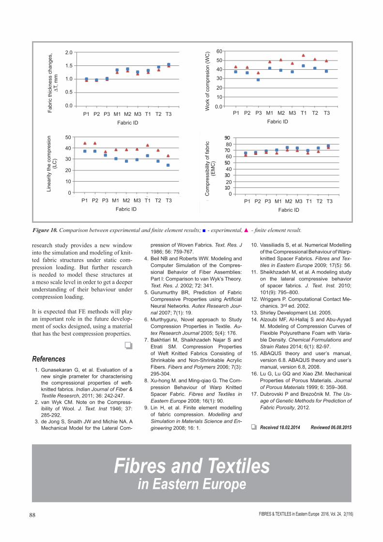
The FE modeling results obtained indi-cate fairly good agreement with experi-mental results (Table 3 and Figure 10). The average error of fabric thickness changes predicted is 5 percent. The slight difference between the results may be due to the short fibres with low density over the fabric surface, which was ig-nored in the FE model. In the model, it was assumed that the fabric is a homoge-nous hyperfoam. However, the real fabric is more compressible than in the model, and hence the experimental compression energy (WC) and fabric compressibility (EMC) values are smaller than the FEM results. The difference between the lin-earity of compression (LC) results may be due to ignoring the friction effect in the model. In general, as shown in Fig-ure 10, the variation trend of compres-sion parameters against knitted fabric types for two experimental and FEM analysis results is almost similar.
n ConclusionsUnlike experimental measurements, finite element analysis has the benefit of quantifying the overall deformation, stress, strain, and displacement distri-bution of a structure to be analysed. In
Table 3. Fabric compression parameter results.
Fabric ID
∆T, mm Error, %
WC cN.cm/cm2 Error, %
LC, % Error, %
EMC, % Error, %Experimental FE model Experimental FE model Experimental FE model Experimental FE model
P1 1.01 0.96 4.6 37.37 42.99 -15.0 37.00 44.64 -20.6 65.66 62.85 4.3
P2 0.98 0.96 2.4 36.59 42.37 -15.7 37.34 44.32 -18.7 66.39 64.59 2.7
P3 1.03 0.99 4.1 32.76 41.15 -24.5 33.63 36.62 12.2 68.77 66.31 3.6
M1 1.34 1.25 6.5 41.07 51.81 -26.2 30.65 38.67 -26.2 70.53 65.95 6.5
M2 1.39 1.32 5.3 39.38 50.71 -28.8 28.33 38.53 -36.0 74.33 70.37 5.3
M3 1.27 1.20 5.7 37.30 46.80 -25.5 29.37 39.06 -33.0 73.46 69.65 5.2
T1 1.32 1.26 4.8 43.87 55.33 -26.1 33.24 42.69 -28.4 69.40 65.76 5.3
T2 1.45 1.34 7.8 41.14 51.17 -24.3 28.37 38.30 -35.0 73.98 68.16 7.9
T3 1.55 1.50 3.4 38.06 49.49 -30.0 24.55 33.04 -34.6 77.23 74.53 3.5
Figure 8. Spatial displacement and stress at a node on the fabric (Fabric ID: P1); ___ - U: U2 P1: Fabric-1 N: 68782, ___ - S: S22(Avg: 75%) P1: Fabric-1 N: 68782.
this study, a FE compression model was developed for knitted fabric based on porous material behaviour. Nonlinear geometric and linear material behav-iours are used in the model. The strains predicted by the model were in good agreement with those measured during compressive loading. In general, this 3D model confirms the compression
properties of single jersey weft knit-ted fabrics to be used as the plantar of socks.
One of the major advantages of the mod-el proposed over other approaches is that all kinds of textile fibre assemblies under compressive loading can be modelled. The modelling approach proposed in this
Figure 9. Typical curve of pressure against fabric thickness changes (Fabric ID: P1), (Ex-perimental and FEM analysis); - experimental, ■ - finite element result.
Time4.03.02.01.0 5.0 6.0 7.00.0
0.0
-0.2
-0.4
-0.6
-0.8
-1.0S
tress
0.00
-0.05
-0.10
-0.15
-0.20
Pre
ssur
e, M
Pa
0.25
0.20
0.15
0.10
0.05
0.00
Fabric thickness, mm2.01.0 1.50.50.0
0
0.05
0.1
0.15
0.2
0.25
0 0.5 1 1.5 2
Pres
sure
, MPa
Fabric thickness, mm
FIBRES & TEXTILES in Eastern Europe 2016, Vol. 24, 2(116)88
research study provides a new window into the simulation and modeling of knit-ted fabric structures under static com-pression loading. But further research is needed to model these structures at a meso scale level in order to get a deeper understanding of their behaviour under compression loading.
It is expected that FE methods will play an important role in the future develop-ment of socks designed, using a material that has the best compression properties.
References 1. Gunasekaran G, et al. Evaluation of a
new single prameter for characterising the compressional properties of weft-knitted fabrics. Indian Journal of Fiber & Textile Resesrch, 2011; 36: 242-247.
2. van Wyk CM. Note on the Compress-ibility of Wool. J. Text. Inst 1946; 37: 285-292.
3. de Jong S, Snaith JW and Michie NA. A Mechanical Model for the Lateral Com-
pression of Woven Fabrics. Text. Res. J 1986; 56: 759-767.
4. Beil NB and Roberts WW. Modeling and Computer Simulation of the Compres-sional Behavior of Fiber Assemblies: Part I: Comparison to van Wyk’s Theory. Text. Res. J. 2002; 72: 341.
5. Gurumurthy BR, Prediction of Fabric Compressive Properties using Artificial Neural Networks. Autex Research Jour-nal 2007; 7(1): 19.
6. Murthyguru, Novel approach to Study Compression Properties in Textile. Au-tex Research Journal 2005; 5(4): 176.
7. Bakhtiari M, Shaikhzadeh Najar S and Etrati SM. Compression Properties of Weft Knitted Fabrics Consisting of Shrinkable and Non-Shrinkable Acrylic Fibers. Fibers and Polymers 2006; 7(3): 295-304.
8. Xu-hong M. and Ming-qiao G. The Com-pression Behaviour of Warp Knitted Spacer Fabric. Fibres and Textiles in Eastern Europe 2008; 16(1): 90.
9. Lin H, et al. Finite element modelling of fabric compression. Modelling and Simulation in Materials Science and En-gineering 2008; 16: 1. Received 18.02.2014 Reviewed 06.08.2015
Figure 10. Comparison between experimental and finite element results; ■ - experimental, ▲ - finite element result.
10. Vassiliadis S, et al. Numerical Modelling of the Compressional Behaviour of Warp-knitted Spacer Fabrics. Fibres and Tex-tiles in Eastern Europe 2009; 17(5): 56.
11. Sheikhzadeh M, et al. A modeling study on the lateral compressive behavior of spacer fabrics. J. Text. Inst. 2010; 101(9): 795–800.
12. Wriggers P. Computational Contact Me-chanics. 3rd ed. 2002.
13. Shirley Development Ltd. 2005.14. Alzoubi MF, Al-Hallaj S and Abu-Ayyad
M. Modeling of Compression Curves of Flexible Polyurethane Foam with Varia-ble Density. Chemical Formulations and Strain Rates 2014; 6(1): 82-97.
15. ABAQUS theory and user’s manual, version 6.8. ABAQUS theory and user’s manual, version 6.8, 2008.
16. Lu G, Lu GQ and Xiao ZM. Mechanical Properties of Porous Materials. Journal of Porous Materials 1999; 6: 359–368.
17. Dubrovski P and Brezočnik M. The Us-age of Genetic Methods for Prediction of Fabric Porosity, 2012.
Fabric ID
P1 P2 P3 M1 M2 M3 T1 T2 T3Fabric ID
P1 P2 P3 M1 M2 M3 T1 T2 T3
Fabric ID
P1 P2 P3 M1 M2 M3 T1 T2 T3
Fabric ID
P1 P2 P3 M1 M2 M3 T1 T2 T3
2.0
1.5
1.0
0.5
0.0
40
30
20
10
0
80
60
40
20
0
50
40
30
20
10
0.0
50
60Fa
bric
thic
knes
s ch
ange
s,
DT, m
mLi
near
ity th
e co
mpr
esio
n (L
C)
Com
pres
sibi
lity
of fa
bric
(E
MC
)W
ork
of c
ompr
esio
n (W
C)
Fibres and Textiles in Eastern Europe