zbdd 0055 zbinst1159 diem2 guidelines metalic manual
TRANSCRIPT

DIEM® 2 Guidelines
Procedure Manual


Introduction . . . . . . . . . . . . . . . . . . . . . . . . . . . . . . . . . . . . . . . . . . . . . . . . . . . . . . . . . . . . . . . . . . . . . . . 1
Treatment Planning Considerations . . . . . . . . . . . . . . . . . . . . . . . . . . . . . . . . . . . . . . . . . . . . . . . . . . . 3
Low Profile Abutment Selection . . . . . . . . . . . . . . . . . . . . . . . . . . . . . . . . . . . . . . . . . . . . . . . . . . . . . . 4
DIEM 2 Surgical Flowchart . . . . . . . . . . . . . . . . . . . . . . . . . . . . . . . . . . . . . . . . . . . . . . . . . . . . . . . . . . . 5
DIEM 2 Guidelines - Restorative Procedure For Denture Conversion . . . . . . . . . . . . . . . . . . . . . . 7
DIEM 2 Guidelines - Restorative Procedure For Definitive Prosthesis . . . . . . . . . . . . . . . . . . . . .11
DIEM 2 Ordering Information . . . . . . . . . . . . . . . . . . . . . . . . . . . . . . . . . . . . . . . . . . . . . . . . . . . . . . .19
References . . . . . . . . . . . . . . . . . . . . . . . . . . . . . . . . . . . . . . . . . . . . . . . . . . . . . . . . . . . . . . . . . . . . . . .20
Table Of Contents

DIEM 2DIEM, the Latin word for day, was chosen as the name for an immediate full-arch rehabilitation solution of the edentulous mandible .
Now, this solution has been expanded with the DIEM 2 Guidelines – a solution for rehabilitation in both arches, utilizing innovative products to deliver full-arch fixed provisional prostheses in as little as one day .*
In the 1960s, loading dental implants with functional occlusal forces immediately after implant placement frequently resulted in fibrous encapsulation of implants in alveolar bone . This led to relative degrees of implant mobility and ultimately the loss of implants with the potential loss of the prostheses .1
In the 1970s, Brånemark et al .2 described surgical and prosthetic protocols that included unloaded healing periods of approximately four months for mandibular implants and six months for maxillary implants .3
Throughout the last three decades, the use of dental implants has grown significantly throughout the world and under certain specific clinical circumstances, IOL (Immediate Occlusal Loading) of endosseous implants was found to be as efficacious as the results clinicians obtained with previously reported unloaded healing protocols .4-10
Two of the primary benefits of IOL Protocols include reduction in the number of surgical procedures and the amount of time required for insertion of immediate, fixed, provisional prostheses . This is especially true for patients with debilitated dentitions who no longer have to go through prolonged healing periods, which include wearing complete dentures . In order for clinicians and patients to select an IOL Protocol, the protocols must provide at least similar implant survival rates as compared to the Cumulative Survival Rates (CSRs) associated with unloaded healing protocols .
Years of evidence-based research drove the development of clinical guidelines for each type of immediate loading procedure: Immediate Occlusal Loading in the edentulous mandible and Immediate Occlusal Loading in the edentulous maxillae .
Immediate Occlusal Loading In The Edentulous MandibleAuthors have reported favorable results for Immediate Occlusal Loading in edentulous jaws . In 1997, Tarnow† et al . reported 98% Cumulative Survival Rates (CSR; six mandibular, four maxillary jaws) 1-6 years post implant placement (patients in study = 10) .6 In 2002, Cooper et al . reported 98% CSR 18 months post implant placement (patients in
study = 15) .7 In 2003, Testori† et al . reported one failure due to infection, in a study involving 92 Osseotite® Implants that were immediately loaded with fixed prostheses in edentulous mandibles . Testori et al . reported a 98 .9% CSR for Osseotite Implants up to 48 months post implant placement .
More recently in 2009, Pieri et al . reported a 98 .6% CSR in which 144 implants in 23 patients were restored with full-arch restorations immediately post implant placement . Pieri et al suggested that implants placed immediately after multiple extractions is a viable treatment option for edentulous arches when implants are stable at the time of placement and rigidly splinted with screw-retained titanium-resin prostheses .11
* Not all patients are candidates for immediate load procedures .
Introduction

Immediate Occlusal Loading In The Edentulous MaxillaeEdentulous maxillary jaws are, in general, remarkably different from edentulous mandibles at macroscopic and microscopic levels . This is especially true when comparing the anterior, inter-foraminal portion of edentulous mandibles to anterior maxillary segments; maxillary bone is much more
trabecular and, therefore, less dense .12,13 Therefore, in some cases, it is much more difficult to achieve high levels of implant stability at implant placement (primary stability) for maxillary implants . Primary implant stability is considered to be one of the most important factors for achieving successful osseointegration of dental implants .13,14
In soft bone, undersizing implant osteotomies at the time of surgery, and selecting implants with differing shapes, lengths and diameters may help to overcome some of these anatomic limitations and allow implants to be placed with high primary stability .15,16 Implant insertion torques of at least 40 Ncm have been suggested as the minimum value acceptable for Immediate Occlusal Loading,16 although there is some debate on this subject, specifically as it pertains to multiple, splinted implants versus single, un-splinted implants .17,18
In the last several years, a number of reports have addressed the treatment of edentulous maxillary jaws with implant-supported prostheses utilizing both straight and tilted implant placement protocols using four or more implants .19-25 In a literature review of maxillary Immediate Occlusal Loading studies in 2006, Del Fabbro et al .18 found a wide variety of studies in terms of the number of implants placed by clinicians for maxillary Immediate Occlusal Loading protocols, as well as differing surgical and prosthetic protocols . These studies reported that the mean number of maxillary implants placed for Immediate Occlusal Loading was eight .17
In 2009, Romanos and Nentwig reported the results of a prospective clinical trial regarding Immediate Occlusal Loading for maxillary implants .26 Ninety implants were placed (six in each maxillary arch) in 15 patients . Immediately after surgery, the implants were loaded with provisional acrylic resin prostheses (Immediate Occlusal Loading) . The provisional prostheses remained in function for six to eight weeks; a soft/liquid diet was recommended for this time period . Definitive fixed restorations were fabricated and delivered approximately 6-8 months post implant placement . Romanos and Nentwig reported three implant failures after a mean loading period of 42 .4 (±19 .15) months (CSR 96 .7%) . Romanos and Nentwig concluded that immediately loaded splinted maxillary implants can be used successfully when implant primary stability, cross-arch stabilization and soft diets for the initial stages of healing have been prescribed and followed .
* Not all patients are candidates for immediate load procedures .
2

Pre-Treatment Diagnostic ConsiderationsSurgeon, Restorative Dentist and Laboratory Technician:• Review medical history/medical consultation as needed• Clinical and radiographic evaluations
Clinical Evaluation ConsiderationsExtraoral Factors:• Skeletal/dental malocclusion• Temporomandibular joint health/disease• Mandibular range of motion
Intraoral Factors:• Condition of the remaining teeth• Soft-tissue contours, type and thickness• Condition of the alveolar bone
Prosthetic Factors:• Pre-prosthetic determination of the vertical dimension
of occlusion, lip support, incisal display at rest, speaking, smiling, lip mobility and resulting transition zone
• Interarch distance• Condition of pre-existing dentures; need and design
considerations for provisional restorations
Radiograph Options:• CT scans• Periapical radiographs• Panoramic radiographs
Treatment Indications For Immediate Implant Prostheses
• Adequate bone quality equal to or greater than Type III• Adequate bone volume for implant placement• Adequate restorative volume that provides space for
implant restorative components and prostheses• Adequate A/P spread (curvature of the arch) for optimal
positioning of implants and to decrease the extent of cantilevers .
Patients With The Following Are Not Considered To Be Optimal Candidates For Immediate Occlusal Loading:• Systemic diseases: - Bleeding disorder - Uncontrolled metabolic disease (Diabetes) - Uncontrolled cardiovascular disease - Uncontrolled hypertension - Compromised immune system
(autoimmune diseases, HIV)• Parafunctional habits• Poor bone quality - Type IV (implants unable to achieve
primary stability)• Lack of bone quantity• Limited arch curvature (poor A/P spread)
A/P Spread DefinedThe A/P, or anterior/posterior spread is a formula used to calculate the maximum cantilever length distal to the most posterior implants for fixed restorations . It is calculated by measuring the distance between two parallel lines; one drawn across the distal most posterior implants and one drawn through the center of the most anterior implant . A line perpendicular to these lines is drawn; this number is multiplied by 1 .5 .27 This length represents the maximum lengths for cantilevered segments within the framework/prosthesis . The number should be decreased for immediate all-acrylic resin restorations and for patients diagnosed with parafunctional habits including bruxism and clenching .
General InformationThe DIEM 2 Guidelines have been designed to serve as a reference for dental practitioners utilizing Biomet 3i components and instrumentation for the Immediate Occlusal Loading of the edentulous mandible or maxilla .
This document is not intended for use as a substitute for professional training and experience or to replace or supersede sound medical judgment . Zimmer Biomet Dental does not provide medical advice . The clinician should use medically sound treatment planning and procedures for predictable results .
10 mm implant A/P Spread allows for 15 mm cantileverNo greater than 1.5 A/P Spread recommended for cantilever length
40
30
20
10010
040
3030
20
1001010
10 mm
15 mm
10 mm A/P Spread x 1.5 = 15 mm Cantilever
Treatment Planning Considerations
Dense (Type I)
Medium (Type II)
Medium (Type III)
Soft (Type IV)

Low Profile One-Piece AbutmentsDesigned for use with multiple-unit restorations . These do not have anti-rotation features at the base of the restorative platform and do not engage the hex of the implant . Non-hexed restorative components are used with these abutments .
Low ProfileAngled AbutmentsDesigned for use with single and multiple-unit restorations; are available in 17 and 30 degree angles . These abutments have hexed configurations at the base of the restorative platforms for anti-rotation and to engage the hex of the implant . Hexed and non-hexed restorative components can be used with these abutments .
Abutment SelectionAbutment selection should be discussed by the implant team as part of the treatment planning process . With the advent of CT scans and three dimensional treatment planning, definitive abutment selection can be accomplished prior to surgery . In the event that implants are not placed vertically, the use of angled abutments may be required .
In order to accomplish accurate abutment selection, clinicians need to be aware of the following six characteristics:28
1 . Implant/abutment connection2 . Diameter of the implant restorative platform3 . Emergence profile of the healing abutment4 . Peri-implant soft-tissue depths5 . Implant angulation6 . Interarch distance
Surgical Materials Required• T3® or Certain® Tapered Implants in lengths
of 10 mm or greater, determined during treatment planning
• Surgical kit
Restorative Materials Required• Low Profile Abutments• Low Profile Components: - Low Profile Polishing Protectors - Gold-Tite® or Titanium Retaining Screws - Waxing Screws - Non-Hexed Temporary Cylinders
Other Materials Required - Light/medium rubber dam and punch - Impression material adhesive - Vinyl Polysiloxane (VPS) occlusal registration material
(quick set) - Heavy body VPS impression material - Equipment for polishing acrylic resin - Syringe for acrylic resin - Dappen dishes - Small paint brushes - Cross-cut carbide bur for titanium cylinders - Acrylic resin (auto-polymerizing or light cure) - Acrylic trimming burs - Articulating paper
• Instruments needed: - Abutment Driver (PAD00) - Abutment Driver Tip (RASA3) - Large Hex Driver (PHD02N or PHD03N) - Large Hex Driver Tip (RASH3N or RASH8N) - Low Torque Indicating Ratchet Wrench (L-TIRW)
Low Profile Abutments
Indications:• Single and multiple-unit screw-retained
restorations• Adequate interarch distance to accept
a hybrid restoration• Minimum soft-tissue height of 1 .0 mm
• Angle correction up to 30º• External hex connection 3 .4 mmD
Low Profile Abutments are limited for use in anterior segments only
Low Profile Abutment Selection 4

Fabricate the provisional denture or use an existing denture .
Duplicate the denture and fabricate the surgical guide .
Clear Acrylic Resin Surgical GuideIf you do not wish to use CT planning software for the surgical guide, fabricate a provisional denture or use an existing denture to duplicate the surgical guide in clear acrylic resin .
For a more predictable outcome, the use of a surgical guide is recommended . Based on clinical preference and experience, a guide fabricated with CT planning software or a guide fabricated from the existing denture can be used .
The Tapered Navigator® System For Guided SurgeryThe Tapered Navigator System for Guided Surgery allows clinicians to place and provisionalize Biomet 3i Implants . Because the system is open architecture, it is compatible with a variety of CT planning software and surgical guide providers .
For more information on our guided surgery solution, please reference the Biomet 3i Tapered Navigator System for Guided Surgery Manual (INST1149 ) .
DIEM 2 Surgical Flowchart
Surgical Guide

Implant Placement1. Tilted implant placement with four or more implants . The posterior-most implants must be tilted at 45° or less .2. Straight implant placement with six or more implants . Sinus grafting may be necessary .
Tilted Straight
Low Profile Abutment SelectionSelect the appropriate height for each Low Profile Abutment . The abutment height should be 1-2 .0 mm supragingival, keeping the abutment platforms as level as possible . Low Profile Abutments should be selected so that the prosthetic access openings emerge through the occlusal surfaces of the posterior teeth and in the region of the cingulums of the anterior teeth .
Select and seat the Low Profile Abutments .
6

DIEM 2 Guidelines
1. Fill the interior portion of the provisional denture with quick set occlusal registration material .
2. Seat the denture into the mouth . If working on the maxilla, use the palatal portion of the maxillary prosthesis to accurately and completely seat the prosthesis . Make sure the dental midline is consistent with the facial midline . Have the patient close into centric occlusion . Let the quick set occlusal registration material set in the intaglio surface of the prosthesis .
3. Remove the denture . The locations of the Low Profile Abutments have been recorded in the impression . Through the impression material, drill holes into the denture at the abutment locations identified . Drill each hole slightly larger than the diameters of the Low Profile Abutments .
4. Identify the locations of the Low Profile Abutments on a piece of rubber dam; the entire sheet does not have to be used (trim as needed) . Punch or cut holes at the abutment locations and trim the rubber dam to follow the curvature of the arch .
5. Place Non-Hexed Temporary Cylinders (LPCTC2) onto the Low Profile Abutments and secure them with a Gold-Tite or Titanium Retaining Screw (LPCGSH or LPCTSH) using the Large Hex Driver (PHD02N or PHD03N) until finger-tight . Make sure all of the cylinders are completely seated onto the abutments . Try-in the denture to make sure that none of the cylinders interfere with seating the denture into its correct position . Evaluate the occlusion to verify that there is no interference from any of the cylinders with the denture fully seated .
Restorative Procedure For Denture Conversion

8
6. At this time, if one or more of the Non-Hexed Temporary Cylinders (LPCTC2) interfere with seating, reduce its height only enough to clear the opposing occlusion . Do not prepare the cylinders flushed with the occlusal surface of the denture unless the occlusion requires it . Generally, the heights of the posterior cylinders need to be trimmed so as to not interfere with the occlusal relationships .
7. Block out the screw heads with cotton or another suitable material inside the Non-Hexed Temporary Cylinders (LPCTC2) to prevent acrylic resin from entering the access openings during the pick-up procedure .
9. Load a monojet syringe or hand mix of autopolymerizing acrylic resin and inject or spread the material around the base of the Non-Hexed Low Profile Temporary Cylinders (LPCTC2) .
8. Remove the denture from the mouth and fit the rubber dam over the Non-Hexed Temporary Cylinders (LPCTC2) . The apical portions of these cylinders have been machined with concavities to retain the rubber dam . This will separate the surgical and prosthetic fields .
At this time you can try-in the denture once more after it has been adjusted, over the cylinders . If needed, continue to relieve the acrylic resin at the cylinder locations . Ensure that the denture seats completely and that it does not contact any of the restorative components .

DIEM 2 Guidelines
10. Inject or spread resin into the intaglio surface of the denture and seat the denture over the Non-Hexed Temporary Cylinders (LPCTC2) . Have the patient close lightly into centric occlusion . Make sure that the denture is positioned properly – midline, occlusion, anterior-to-posterior, horizontal and vertical dimensions can be seen . Let the acrylic resin polymerize completely .
11. Remove all access opening fillers from the Non-Hexed Temporary Cylinders (LPCTC2) . Unscrew the Gold-Tite or Titanium Retaining Screws (LPCGSH or LPCTSH) using the Large Hex Driver (PHD02N or PHD03N) and remove the denture from the Low Profile Abutments . Remove the rubber dam .
At this time, you may choose to place the Low Profile Healing Caps (LPCHC) on the Low Profile Abutments to aid in maintaining tissue contours while the provisional prosthesis is being finished . Secure the healing caps with the Large Hex Driver (PHD02N or PHD03N) until finger-tight .
12. Attach the Low Profile Polishing Protectors (LPCPP) using the Large Hex Driver (PHD02N or PHD03N) to the cylinders embedded in the denture until finger-tight . Visually confirm that the Polishing Protectors are fully seated on the Temporary Cylinders . Fill any voids around the Polishing Protectors with autopolymerizing acrylic resin . Allow the resin to polymerize . Remove flanges, excess resin and minimize the length of the cantilevers .
13. Finish and polish the provisional prosthesis and remove the polishing protectors . Final provisional prosthesis contours should provide the patient with access for oral hygiene .
Restorative Procedure For Denture Conversion
10
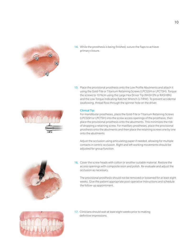
14. While the prosthesis is being finished, suture the flaps to achieve primary closure .
15. Place the provisional prosthesis onto the Low Profile Abutments and attach it using the Gold-Tite or Titanium Retaining Screws (LPCGSH or LPCTSH) . Torque the screws to 10 Ncm using the Large Hex Driver Tip (RASH3N or RASH8N) and the Low Torque Indicating Ratchet Wrench (L-TIRW) . To prevent accidental swallowing, thread floss through the spinner hole on the driver .
Clinical Tip: For mandibular prostheses, place the Gold-Tite or Titanium Retaining Screws
(LPCGSH or LPCTSH) into the screw access openings of the prosthesis, then place the provisional prosthesis onto the abutments . This minimizes the risk of dropping a retaining screw . For maxillary prostheses, place the provisional prosthesis onto the abutments and then place the retaining screws one by one onto the abutments .
Adjust the occlusion using articulating paper if needed, allowing for multiple contacts in centric occlusion . Right and left working movements should be adjusted for group function .
16. Cover the screw heads with cotton or another suitable material . Restore the access openings with composite resin and polish . Re-evaluate and adjust the occlusion as necessary .
The provisional prosthesis should not be removed or loosened for at least eight weeks . Give the patient appropriate post-operative instructions and schedule the follow-up appointment .
17. Clinicians should wait at least eight weeks prior to making definitive impressions .

DIEM 2 Guidelines
First Restorative Appointment – Abutment-Level Impression 1. Remove the screw access opening restorations, unscrew and remove the
provisional prosthesis from the mouth using the Large Hex Driver (PHD02N or PHD03N) . Do not remove the Low Profile Abutments . To prevent accidental swallowing, thread floss through the spinner hole on the driver .
2. Select the proper Low Profile Impression Copings (LPCPIC2) and place them onto the Low Profile Abutments . Tighten the screw using the Large Hex Driver (PHD02N or PHD03N) until finger-tight .
Radiograph the interface to verify complete seating of the coping on the abutment .
3. A custom or stock open impression tray is used for the Pick-Up Impression Technique . Make small holes in the impression tray to allow access to the Impression coping screw head .
4. A medium or heavy body material is recommended for the impression material in the impression tray . Use light-body impression material and syringe around the entire Low Profile Pick-Up Impression Coping (LPCPIC2) .
Restorative Procedure For Definitive Prosthesis

12
7. Load the impression tray and seat it in the mouth . Remove impression material from the top of the screw access hole before it sets . Allow the impression material to set per the manufacturer’s instruction .
8. After the impression material has set, unscrew and remove the screws from the mouth using the Large Hex Driver (PHD02N or PHD03N) . Remove the impression from the mouth .
9. Verify that the impression material has completely adapted around each impression coping and that there is no impression material on the coping’s restorative platform . If impression material is visible on the coping’s restorative platform, this means the impression coping was not completely seated; a new impression will need to be made .
10. Place the provisional prosthesis back into the mouth and attach it by using the Gold-Tite or Titanium Retaining Screws (LPCGSH or LPCTSH) . Torque the screws to 10 Ncm using the Large Hex Driver Tip (RASH3N or RASH8N) and the Low Torque Indicating Ratchet Wrench (L-TIRW) . Cover the screw heads with cotton or another suitable material . Restore the access openings with composite resin . Re-evaluate and adjust the occlusion as necessary . Send the impression to the laboratory for the fabrication of a master cast .

DIEM 2 Guidelines
Laboratory 1. Fabricate a soft-tissue master cast using new, unused Laboratory Analogs
(LPCLA) . To fabricate the master cast, place the Laboratory Analogs for Low Profile Abutments (LPCLA) onto the impression copings (LPCPIC2) . There will not be hex engagement as the impression copings are not hexed . Hold the analog in place while tightening the screws with the Large Hex Driver (PHD02N or PHD03N) until finger-tight . Verify that the impression copings are completely seated on the analogs .
The use of old, damaged or loose fitting analogs can interfere with the scanning and design process and may prevent proper seating of the bar or framework . Cases received with damaged or insufficiently anchored analogs will be returned to the laboratory . If the clinician is sending the impression to a commercial laboratory to pour the impression, do not attach the analog . The dental laboratory will place the analogs .
The soft-tissue material on the master cast must be applied approximately 2 .0 mm down from the analog restorative interface . It must also be easily removable for the scanning and design process to ensure a proper fit .
2. Place the Non-Hexed Low Profile Temporary Cylinders (LPCTC2) onto the abutment analogs and finger-tighten into place with waxing screws (LPCWS) using the Large Hex Driver (PHD02N or PHD03N) . Fabricate a rigid verification index by luting the cylinders together using a light cure composite resin or autopolymerizing acrylic resin . Also, fabricate a record base with a wax occlusion rim . Ship the verification index intact to the clinician for try-in along with the wax occlusion rim for interocclusal records .
Restorative Procedure For Definitive Prosthesis

14
Second Restorative Appointment – Verification Index Try-In1. Remove the screw access opening restorations, unscrew and remove the provisional
prosthesis from the mouth using the Large Hex Driver (PHD02N or PHD03N) . Do not remove the Low Profile Abutments . To prevent accidental swallowing, thread floss through the spinner hole on the driver .
3. Place the provisional prosthesis back into the mouth and attach it by using the Gold-Tite or Titanium Retaining Screws (LPCGSH or LPCTSH) . Torque the screws to 10 Ncm using the Large Hex Driver Tip (RASH3N or RASH8N) and the Low Torque Indicating Ratchet Wrench (L-TIRW) . Cover the screw heads with cotton or another suitable material . Restore the access openings with composite resin . Re-evaluate and adjust the occlusion as necessary .
2. Place the wax occlusion rim into the mouth and make the interocclusal records . Place the verification index onto the Low Profile Abutments intraorally . Finger-tighten a Low Profile Waxing Screw (LPCWS) using the Large Hex Driver (PHD02N or PHD03N) into the posterior-most cylinder of the verification index . Visually, verify a passive fit on all interfaces . Remove the waxing screw and place it into the opposite posterior-most cylinder and repeat . If a fit discrepancy is found, section the index and reassemble it intraorally by luting it with resin material . Remove the index .

DIEM 2 Guidelines
Laboratory1. Verify that the master cast is accurate using the verification index . If a fit discrepancy
is found, remove the inaccurately positioned analogs and replace them in the cast using the corrected verification index . Articulate the casts using the interocclusal record . Set the overdenture teeth on the record base and return the denture wax-up for try-in . If the analogs are not accurate in the master cast, remove the analogs from the cast, re-attach them to the verification index and re-seat the index onto the accurate analogs . Inject dental stone around the analog(s) and allow it to set . The cast is now considered to be accurate . Set the overdenture teeth on the record base and return it for the wax try-in .
Third Restorative Appointment – Verification Index Try-In 1. Remove the screw access opening restorations, unscrew and remove the
provisional prosthesis from the mouth using the Large Hex Driver (PHD02N or PHD03N) . Do not remove the Low Profile Abutments . To prevent accidental swallowing, thread floss through the spinner hole on the driver .
2. Place the wax denture/record base intraorally . Verify occlusion, aesthetics and phonetics . Make any necessary adjustments . If major adjustments are necessary, make a new interocclusal record and return the denture wax-up to the laboratory for remounting of the casts, a new set-up and a second wax try-in .
3. Place the provisional prosthesis back into the mouth and attach it by using the Gold-Tite or Titanium Retaining Screws (LPCGSH or LPCTSH) . Torque the screws to 10 Ncm using the Large Hex Driver Tip (RASH3N or RASH8N) and the Low Torque Indicating Ratchet Wrench (L-TIRW) . Cover the screw heads with cotton or another suitable material . Restore the access openings with composite resin . Re-evaluate and adjust the occlusion as necessary .
Restorative Procedure For Definitive Prosthesis

Laboratory 1. Place the verified denture wax-up on the cast and make a silicone or plaster
matrix of the tooth positions . Do not remove the teeth from the denture wax-up . Do not ship the matrix to the BellaTek® Production Center .
2. Log on to your BellaTek Portal account, complete the BellaTek Bar Work Order Form and send it to The Zimmer Biomet Milling Center .
16
BellaTek Production Center 1. The soft-tissue master cast and the verified denture wax-up are scanned
and transferred into the CAD software . The BellaTek Bar is designed in CAD according to the BellaTek Work Order Form .
2. Once the design has been approved, the design file is transferred to a milling machine for fabrication and milling . After milling is complete, the BellaTek Bar is finished and polished per the Work Order Form . The BellaTek Bar, any requested components and case materials will be returned to the laboratory .
The laboratory may send the BellaTek Bar or Framework to the restorative dentist for intraoral try-in or to set the teeth directly onto the bar . The clinician may do the framework try-in alone or combine the framework try-in with the denture teeth try-in to save one appointment . Once the try-in is completed and the framework fit and aesthetics are verified, the prosthesis may be processed in a conventional manner .

DIEM 2 Guidelines
Fourth Restorative Appointment (Optional) – Framework And Denture Teeth Try-In1. Remove the screw access opening restorations, unscrew and remove the
provisional prosthesis from the mouth using the Large Hex Driver (PHD02N or PHD03N) . Do not remove the Low Profile Abutments . To prevent accidental swallowing, thread floss through the spinner hole on the driver .
2. Fit the BellaTek Bar onto the Low Profile Abutments intraorally . Thread a Low Profile Waxing Screw (LPCWS) using the Large Hex Driver (PHD02N or PHD03N) into the posterior-most access opening until finger-tight . Visually verify a passive fit on all interfaces . There should be no space between the BellaTek Bar and the abutments . Remove the screw and place it into the opposite posterior-most access opening of the BellaTek Bar and repeat .
NOTE: If a fit discrepancy is detected during bar try-in, one of the following corrective measures may be used:
a. The BellaTek Bar may be sectioned and reassembled in the patient replica . Then the analog(s) in the master cast will be repositioned by the laboratory and a new BellaTek Bar will be fabricated .
b. A new impression can be made and a new master cast can be poured . Then, the verification steps should be repeated and a new BellaTek Bar will be fabricated .
3. Place the provisional prosthesis back into the mouth and attach it by using the Gold-Tite or Titanium Retaining Screws (LPCGSH or LPCTSH) . Torque the screws to 10 Ncm using the Large Hex Driver Tip (RASH3N or RASH8N) and the Low Torque Indicating Ratchet Wrench (L-TIRW) . Cover the screw heads with cotton or another suitable material . Restore the access openings with composite resin . Re-evaluate and adjust the occlusion as necessary .
Restorative Procedure For Definitive Prosthesis

Fifth Restorative Appointment – Delivery Of Definitive Prosthesis1. Remove the screw access opening restorations, unscrew and remove the
provisional prosthesis from the mouth using the Large Hex Driver (PHD02N or PHD03N) . Do not remove the Low Profile Abutments . In order to prevent accidental swallowing, thread floss through the spinner hole on the driver .
2. Place the fixed-hybrid prosthesis onto the Low Profile Abutments intraorally and thread the Gold-Tite or Titanium Retaining Screws (LPCGSH or LPCTSH) into the abutments using the Large Hex Driver (PHD02N or PHD03N) until finger-tight . Verify a passive fit on all interfaces . Adjust the denture base as needed . Adjust the occlusion regarding centric, lateral and balancing contacts . Remove the prosthesis, finish and polish only if the prosthesis was adjusted .
* The use of new Gold-Tite Retaining Screws (LPCGSH) is recommended when placing the final prosthesis .
3. Torque the Gold-Tite Screws (LPCGSH) to 10 Ncm using the Large Hex Driver Tip (RASH3N or RASH8N) and the Low Torque Indicating Ratchet Wrench (L-TIRW) . Place protective material over the screw heads inside the access openings . Restore the access openings with composite resin and polish .
18
Laboratory – Fixed Hybrid Restoration 1. Place the denture wax-up and matrix on the cast . Remove the overdenture teeth
and reset the teeth into the matrix . Attach the BellaTek Bar onto the analogs with the use of the Low Profile Waxing Screws (LPCWS) and finger-tighten using the Large Hex Driver (PHD02N or PHD03N) . Place the matrix with the overdenture teeth onto the cast and attach the overdenture teeth to the BellaTek Bar . Finish waxing the fixed hybrid restoration . Flask the denture wax-up . Boil out the denture flask . Separate the flask and remove all wax remnants . Pack, finish and polish .

3.4 mm Seating Surface
Collar Height One Piece (Non-Hexed) Two Piece (Hexed) 17° (Hexed) 30° (Hexed)
1.0 mm ILPC341U LPC341U ILPC341 LPC341 – – – –
2.0 mm ILPC342U LPC342U ILPC342 LPC342 ILPAC3217 LPAC3217 – –
3.0 mm ILPC343U LPC343U ILPC343 LPC343 – – ILPAC3330 LPAC3330
4.0 mm ILPC344U LPC344U ILPC344 LPC344 ILPAC3417 LPAC3417 – –
5.0 mm – – – – – – ILPAC3530 LPAC3530
4.1 mm Seating Surface
Collar Height One Piece (Non-Hexed) Two Piece (Hexed) 17° (Hexed) 30° (Hexed)
1.0 mm ILPC441U LPC441U ILPC441 LPC441 – – – –
2.0 mm ILPC442U LPC442U ILPC442 LPC442 ILPAC4217 LPAC4217 – –
3.0 mm ILPC443U LPC443U ILPC443 LPC443 – – ILPAC4330 LPAC4330
4.0 mm ILPC444U LPC444U ILPC444 LPC444 ILPAC4417 LPAC4417 – –
5.0 mm – – – – – – ILPAC4530 LPAC4530
5.0 mm Seating Surface
Collar Height One Piece (Non-Hexed) Two Piece (Hexed) 17° (Hexed) 30° (Hexed)
1.0 mm ILPC541U LPC541U ILPC541 LPC541 – – – –
2.0 mm ILPC542U LPC542U ILPC542 LPC542 ILPAC5217 LPAC5217 – –
3.0 mm ILPC543U LPC543U ILPC543 LPC543 – – ILPAC5330 LPAC5330
4.0 mm ILPC544U LPC544U ILPC544 LPC544 ILPAC5417 LPAC5417 – –
5.0 mm – – – – – – ILPAC5530 LPAC5530
= Certain® Internal Connection = External Hex Connection
Low Profile Abutments
Low Profile Abutment Bone Profilers
Description Item No.
Low Profile Abutment Bone Profiler, 3 .4 mmD LPCBP3
Low Profile Abutment Bone Profiler, 4 .1 mmD LPCBP4
Low Profile Abutment Bone Profiler, 5 .0 mmD LPCBP5
Low Profile Impression Copings & Analog
Description Item No.
Pick Up Impression Coping (Hexed) LPCPIC1
Pick Up Impression Coping (Non-Hexed) LPCPIC2
Twist Lock™ Impression Coping (Hexed) LPCTIC1
Twist Lock (Non-Hexed) LPCTIC2
QuickBridge® Impression Coping LPCRIC
Lab Analog LPCLA
Low Profile Provisional Restoration Components
Description Item No.
Temporary Cylinder (Hexed) LPCTC1
Temporary Cylinder (Non-Hexed) LPCTC2
Healing Cap LPCHC
PreFormance® Temporary Cylinder (Hexed) LPCPTC1
PreFormance Temporary Cylinder (Non-Hexed) LPCPTC2
QuickBridge LPCQB
QuickBridge Replacement Cap LPCQBCAP
Distal Extension LPCDE
Low Profile Final Restoration Components
Description Item No.
Gold Cylinder (Hexed) LPCGC1
Gold Cylinder (Non-Hexed) LPCGC2
Castable Cylinder (Hexed) LPCCC1
Castable Cylinder (Non-Hexed) LPCCC2
Laser Welded Cylinder LPCTUCA
Large Hex Driver & Driver Tip
Description Item No.
Large Hexed Driver PHD02N, PHD03N*
Large Hexed Driver Tip RASH3N, RASH8N*
Posterior Abutment Driver 17 mmL PAD00
Standard Abutment Driver 24 mmL PAD24
* Made narrower to fit with external hexed angled Low Profile Abutments . The Driver and Driver Tips can be identified by a laser marked dot after the item number as pictured below .
Dot Dot
Low Profile Screws
Description Item No.
Gold-Tite Retaining Screw LPCGSH
Titanium Retaining Screw LPCTSH
Waxing Screw LPCWS
Low Profile Laboratory Tools
Description Item No.
Lapping Tool LPCAMI
Polishing Protector LPCPP
Abutment Compatibility
Component Hexed Abutment Non-Hexed Abutment
Hexed Yes No
Non-Hexed Yes Yes
DIEM 2 Ordering Information

1 . Linkow L, Charchee R . Theories and Techniques of Oral Implantology . St . Louis, MO: Mosby . 1970; pp . 74-76 .
2 . Brånemark PI, Hansson BO, Adell R, et al . Osseointegrated implants in the treatment of the edentulous jaw: experience from a 10-year period . Scand J Plast Reconstr Surg . 1977;2:1-132 .
3 . Albrektsson T, Zarg GA, Worthington P, et al . The long-term efficacy of currently used dental implants: a review and proposed criteria for success . Int J Oral Maxillofac Implants . 1986;1:11-25 .
4 . Schnitman PA, Wohrle PS, Rubenstein JE . Immediate fixed interim prostheses supported by two-stage threaded implants; methodology and results . J Oral Implantol . 1990;16:96-105 .
5 . Schnitman PA, Wohrle PS, Rubenstein JE, et al . Ten-year results for Brånemark implants immediately loaded with fixed prostheses at implant placement . Int J Oral Maxillofac Implants . 1997;12:495-503 .
6 . Tarnow† D, Emtiaz S, Classi A . Immediate loading of threaded implants at stage I surgery in edentulous arches: ten consecutive case reports with 1- to 5-year data . Int J Oral Maxillofac Implants . 1997;12:319-324 .
7 . Cooper LF, Rahman A, Moriarty J, et al . Immediate mandibular rehabilitation with endosseous implants: simultaneous extraction, implant placement and loading . Int J Oral Maxillofac Implants . 2002;17:517-525 .
8 . Horiuchi K, Uchida H, Yamamoto K . Immediate loading of Brånemark system implants following placement in edentulous patients: a clinical report . Int J Oral Maxillofac Implants . 2000;15:824-830 .
9 . Grunder† U . Immediate functional loading of immediate implants in edentulous arches: two-year results . Int J Perio Rest Dent . 2001;6:545-551 .
10 . Testori† T, Meltzer† A, Del Fabbro M, et al . Immediate occlusal loading of Osseotite Implants in the lower edentulous jaw . A multicenter prospective study . Clin Oral Impl Res . 2004;15:278-284 .
11 . Pieri F, Aldini NN, Fini M, Corinaldesi G . Immediate occlusal loading of immediately placed implants supporting fixed restorations in completely edentulous arches: a 1-year prospective pilot study . J Periodontol . 2009;80(3):411-21 .
12 . Jaffin RA, Berman CL . The excessive loss of Brånemark fixtures in type IV bone: a 5-years analysis . J Periodontol . 1991;62:2-4 .
13 . Esposito M, Hirsch JM, Lekholm U, et al . Biological factors contributing to failures of osseointegrated oral implants . (II) Etiopathogenesis . 1998;106:721-764 .
14 . Lekholm U, Zarb GA . Patient selection and preparation . In Brånemark PI, Zarb GA, Albrektsson T (eds): Tissue-Integrated Prostheses: Osseointegration in clinical dentistry . Chicago, Quintessence . 1985; pp . 199-202 .
15 . Friberg B, Jemt T, Lekholm U . Early failures in 4,641 consecutively placed Brånemark dental implants . A study from stage I surgery to the connection of completed prostheses . Int J Oral Maxillofac Implants . 1991;6:142-146 .
16 . Adrianssens P, Herman M . Immediate implant function in the anterior maxilla: a surgical technique to enhance primary stability for Brånemark MKIII and MKIV implants . A randomized, prospective clinical study at the 1-year follow-up . Appl Osseoint Res . 2001;2:17-21 .
17 . Van Den Bogaerde L, Pedretti G, Dellacasa P, et al . Early function of splinted implants in maxillas and posterior mandibles using Brånemark system machined-surface implants: an 18-month prospective clinical multicenter study . Clin Implant Dent Relat Res . 2003;5(Suppl 1):21-28 .
18 . Del Fabbro M, Testori† T, Francetti L, et al . Systematic review of survival rates for immediately loaded dental implants . Int J Periodontics Restorative Dent . 2006;26:249-263 .
19 . Calandriello R, Tomatis M . Simplified treatment of the atrophic posterior maxilla via immediate/early function and tilted implants: a prospective 1-year clinical study . Clin Implant Dent Rel Res . 2005;7:1-12 .
20 . Malo P, Rangert B, Nobre M . All-on-4 immediate function concept with Brånemark system implants for completely edentulous maxillae: a 1-year retrospective clinical study . Clin Implant Dent Relat Res . 2005;7 (Suppl 1):S88-S94 .
21 . Balshi SF, Wolfinger GJ, Balshi TJ . A prospective study of immediate functional loading, following the Teeth in a Day protocol: a case series of 55 consecutive edentulous maxillas . Clin Implant Dent Relat Res . 2005;7:24-31 .
22 . Capelli M, Zuffetti F, Del Fabbro M, Testori† T . Immediate rehabilitation of the completely edentulous jaw with fixed prostheses supported by either upright or tilted implants: a multicenter clinical study . Int J Oral Maxillofac Implants . 2007;22:639-644 .
23 . Testori† T, Del Fabbro M, Capelli M, Zuffetti F, Francetti L, Weinstein RL . Immediate occlusal loading and tilted implants for the rehabilitation of the atrophic edentulous maxilla: 1-year interim results of a multicenter prospective study . Clin Oral Implants Res . 2008;19:227-232 .
24 . Fazi G, Tellini S, Vangi D, Branchi R . Three-dimensional finite element analysis of different implant configurations for a mandibular fixed prosthesis . Int J Oral Maxillofac Implants . 2011;26:752-759 .
25 . Baghai Naini R, Nokar S, Borghei H, Alikhasi M . Tilted or parallel implant placement in the completely edentulous mandible? A three-dimensional finite element analysis . Int J Oral Maxillofac Implants . 2011;26:776-781 .
26 . Romanos GE, Nentwig GH . Immediate functional loading in the maxilla using implants with platform switching: five-year results . Int J Oral Maxillofac Implants . 2009;24(6):1106-12 .
27 . English C . E . The critical A-P Spread . The Implant Society . March-April 1990;1(1):2-3 .
28 . Drago† C, Lazzara† R . Guidelines for implant abutment selection for partially edentulous patients . Comp Cont Dent Ed . 2010;31:14-28 .
† The indicated clinicians have financial relationships with Zimmer Biomet Dental resulting from speaking engagements, consulting engagements and other retained services .
References 20

Unless otherwise indicated, as referenced herein, all trademarks are the property of Zimmer Biomet; and all products are manufactured by one or more of the dental subsidiaries of Zimmer Biomet Holdings, Inc . and marketed and distributed by Zimmer Biomet Dental and its authorized marketing partners . For additional product information, please refer to the individual product labeling or instructions for use . Product clearance and availability may be limited to certain countries/regions . This material is intended for clinicians only and does not comprise medical advice or recommendations . Distribution to any other recipient is prohibited . This material may not be copied or reprinted without the express written consent of Zimmer Biomet Dental . ZBINST1159 REV B 01/20 ©2020 Zimmer Biomet, All rights reserved .
Zimmer Biomet Dental
Global Headquarters
4555 Riverside Drive
Palm Beach Gardens, FL 33410
Tel: +1-561-776-6700
Fax: +1-561-776-1272
Contact us at 1-800-342-5454 or visit
zimmerbiometdental.com