zenair stol ch 701 - zenith aircraft company · on the ground, before engine is started. 1. go on...
TRANSCRIPT

������������
Flight Manual
ZENAIR STOL CH 701
Serial number:
Registration:
Czech Aircraft Works, Czech Republicedition. 3 CZ - March 99

������������
1. General 2
2. Limitations 4
3. Emergency procedures 8
4. Normal procedures 10
5. Performance 14
6. Weight and balance/equipment list 16
7 . Aircraft and systems description 19
8. Aircraft handling, servicing nrui maintenance 23
9. Supplements 27
The structure of document was changed according to requirements of BCAR Section S andchanges due to MTOW 450 kg with respect to JAR-VLA rules.

������������
1. General
IntroductionThe pilot’s handbook has been prepared to provide pilots and instructors withinformation for the safe and efficient operation of this UL-aeroplane.
Certification basisThis type of aircraft has been approved by PFA according to British Civil AirworthinessRequirements CAP 482 Section S Small Light Aeroplanes, Issue 1 including BCAR PaperS901 proposed amendments.
Descriptive data
CH 701 is a side-by-side two place, strut-braced high wing monoplane with all-metalstructure. CH 701 is a reliable two seat aircraft designed with pilot and passenger comfort inmind for short-field capability, excellent performance and good visibility. The STOL CH701 is truly the aircraft which combines the advantages of a conventional aircraft with thoseof an advanced Ultralight.Standard powerplant is Rotax 912, 4-cylinder, 4-stroke, w/ opposed cylinders
Wing span ................................................................ 8,220 mmLength ...................................................................... 6,100 mmHeight.. ..................................................................... 2,350 mmMAC ........................................................................ 1.43 mWing area ................................................................. 11.33 m.sq.Wing loading ............................................................ 39.7 kg/m.sq.Engine ...................................................................... Rotax 912 80 HPPropeller.. ................................................................. two or three blade composite or woodDiameter ................................................................... 1700 mm.

������������
Three-view drawing:
30.7”(780 mm.) I
87.5" (2220 mm.)I 27FI. 18220mm)
������������
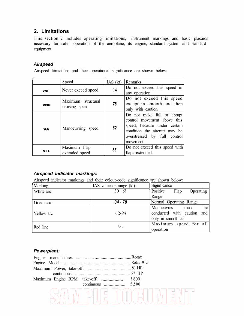
2. LimitationsThis section 2 includes operating limitations, instrument markings and basic placardsnecessary for safe operation of the aeroplane, its engine, standard system and standardequipment.
AirspeedAirspeed limitations and their operational significance are shown below:
VNE
r
VNO
VA
VFE
Speed
Never exceed speed
Maximum structuralcruising speed
Manoeuvring speed
Maximum Flapextended speed
Airspeed indicator markings:
T
IAS (kt)
94
78
62
55
RemarksDo not exceed this speed inany operationDo not exceed this speedexcept in smooth and thenonly with cautionDo not make full or abruptcontrol movement above thisspeed, because under certaincondition the aircraft may beoverstressed by full controlmovementDo not exceed this speed withflaps extended.
Airspeed indicator markings and their colour-code significance are shown below:MarkingWhite arc
IAS value or range (kt)30 - 55
Green arc 34 - 78
Yellow arc
Red line
SignificancePositive Flap OperatingRangeNormal Operating RangeManoeuvres must beconducted with caution andonly in smooth airMaximum speed for alloperation
Powerplant:Engine manufacturer.................... . ...............................RotaxEngine Model:. ............................................................Rotas 912Maximum Power, take-off .......................................... 80 HP
continuous: ................................................ .77 HPMaximum Engine RPM, take-off.. .......................... 5 800
continuous ........................ 5,,500

������������
Maximum Cylinder Head Temperature: . . . . . . . 150 deg.CMaximum Oil temperature. . . . . . . . . . . . . . . . . . . 140 deg. COil Pressure, Minimum. . . . . . . . . . . . . . . . . . . . . 1.5 bar
Maximum . . . . . . .. . . . . . . . . . . . . 5 barFuel Pressure . . . . . . . . . . . . . . . . . . . . . . . . . . . . 0. 15 - 0.4 barFuel grade.. . . . . . . . . . . . . . . . . . . . . . . . . . . . . . . Premium grade leaded gas, according to
DlN1600, O N O R M C1103 E U R OSUPER ROZ 95 unleaded, according toDIN51603, ONORM C 1101
Oil grade . . . . . . . . . . . . . . . . . . . . . . . . . . . . . . . . . . SAE 20 W 50 or SAE 30 Highperformance automotive oil API, S6,Mobil 1, 15 W50, NO AVIATION OIL
Propeller manufacturerPropeller modelPropeller Blade angle - see propeller manual
Powerplant instrument markings:Powerplant instrument markings and their colour code are shown below:
Instrument Red lineMinimumlimit
Green Arc Yellow Arc Red lineNormal operating Caution range Maximum limit
Tachmeter 2 500 -5 500 5 500 - 5 800 5 800Oil TemDerature deg.C 50 90- 110 110- 140 140Cyl. head temp. deg.C 150Fuel (bar)pressure 0.15 0.4Oil (bar)pressure 1 .5 4-5 5
Weight:Basic Empty weight..................................................... 760 kg.Maximum take-off weight .......................................... 450 kgMaximum landing weight.. ......................................... 450 kgMaximum cockpit weight .......................................... .190 kgMinimum cockpit weight.. ......................................... .55 kgMaximum weight in Baggage compartment.. ............ .I8 kg
Centre of gravity:Standard entre of gravity position for empty aircraft is 21.6 % MAC ( 3 10 mm fromreference datum - leading edge of slats)
Allowable Range: 20 - 35 % (286 mm to 500 mm)
See section 6 Weight & Balance for details
������������
Approved manoeuvres:No aerobatics manoeuvres including intentional sppining are approved
Manoeuvring load factors:Limit load factor: positive 4 negative 2
The ultimate load factors are the limit-load factors multiplied by the safety factor of 1.5
Flight crew:Minimum number of crew members is 1 and maximum total number of occupants is 2
Kinds of operations:The aeroplane may be operated in day VFR non-icing condition.
Fuel:Total capacity: . . . . . . . . . . . . . . . . . . . . . . . . . . . . . . . 42 litresUsable fuel : . . . . . . . . . . . . . . . . . . . . . . . . . . . 1.5 litresUnusable fuel : . . . . . . . . . . . . . . . . . . . . . . . . . . . . . . . 40.5 litresApproved fuel grades: . . . . . . . . . . . . . . . . . . . . . . . . . . Premium grade leaded gas, according to
DIN1600, ONORM Cl 103 EUROSUPER ROZ 95 unleaded, according toDlN51603, ONORM C 1101

������������
Limitation placards:The following limitation placards are placed inside the cockpit:
Never-exceed speed VNE.. .......................................................94 ktManoeuvring speed VA.. ......................................................... 62 k tMaximum speed for flaps extended VFE ............................55 kt
Maximum Engine RPM,take-off (5 min) ........ 5 800continuous.. ............. 5 500
Maximum Cylinder Head Temperature: ......... 150 deg.C
Maximum Oil temperature ............................. 140 deg.C
Maximum loading 18 kg(40 Ibs)
No loose items
Allowable fuel in litresbaggage weight (kg)
crew weight(kg) 0 9 18
55 42 42 4280 42 42 42
100 42 I 42 I 42140 42 42 42
This aeroplane is classified as a small lightaeroplane approved for day VFR only, in
non-icing condition. All aerobaticsmanoeuvres including intentional spinning
are prohibited.

������������
3. Emergency procedures
This section provides checklist and amplified procedures for coping with emergenciesthat may occur. Emergencies caused by aeroplanes or engine malfunction are extremelyrare if proper preflight inspections and maintenance are practised.However, should an emergency arise, the basic guidelines described in this section shouldbe considered and applied to correct the problem.
Emergency landing:1. Set airspeed for best rate of Descent 45 kt, flaps up2. Shut off fuel3. Shut off engine4 . Tighten seat belts and harness
Avoid tight turns. In some cases, the flaps may be extended before touchdown. Land as usual,straight ahead power-off approach. Do not try to do any turns - the loss of altitude whilegliding is marginal.
Accidental spins:To recover from a spin:
1. Pull throttle to idle position2. push rudder opposite the spin’s rotation3. bring the pitch control slightly forward.
Fires:On the ground, before engine is started.
1. Go on pushing starter2. Shut off fuel3. Open throttle full as soon as engine starts to blow the fire out
On the ground, engine running.1. Cabin heat off2. shut off fuel3. throttle open to blow fire out
In the air.1. Cabin heat off2. Fuel off3. Ignition off4. Electrics off5. Perform an emergency landing
Do not attempt to restart engine after in-flight fire !!!!!!

������������
Fire in cockpit1. Electrics off2. Cabin heat off3. Use fire extinguished
To restart engine in flight (after fuel sfarvafion):Pull choke before starting and choke in as soon as engine starts.
Note: Make sure that the aircraft is equipped with a functioning fire extinguisher which iseasily accessible to the pilot. It is recommended to equip the aircraft with an EmergencyLocator Transmitter (ELT) and First Aid Kid.

������������
4. Normal procedures
Section 4 provides checklist and amplified procedures for the conduct of normaloperation.
Obtain adequate professional flight training on the STOL CH 701 and the required pilotlicence before attempting operation of the aircraft.
Pre-flight inspection: (“walk around” before each flight):
1. Ignition switch off, fuel open, controls free.2. Drain gascolator and all drain valves to ensure that no water is in the fuel lines check
cowl fasteners for looseness, check spinner and prop. You may want to remove the cowlto check the exhaust and general engine condition for safety. Check fuel quantity as wellas coolant level and water pump.
3. Make a visual check of the front wing attachment points, pitot static, upper forwardstrut attachment (remove tie down), condition of slats and wing tip. Folding wings(option) confirm that the push-pull tubes’ quick release connections are secure.
4. Flaperon, check general condition, hinges, rear strut attachment, flaperon control and rearwing attachment points
5. Landing gear condition, attachments, tires6. Stabilator attachments, elevator and rudded hinges, cables and attachments, controls
stops (remove rear tie down).
Continue walk around in reverse order.
2
4
Before starting engine:Operate controls and make a rapid visual check for proper operation. Make surewindshield is clean for maximum visibility. Check brakes, and fasten and check safety belt.
������������
Starting engine:(Refer also to the engine Manual for detailed information)1. fuel valve ON2 . cock - pull (only for cold engine)3. throttle - idle4. master switch -ON5. ignition switch ON6 . turn starter key to start the engine.
When engine start, set RPM to 2 500. Check oil pressure - it must raise during 10 sec. afterengine start. Do not increase RPM before oil pressure of 2 bar is reached.
7. Release choke gradually when engine starts.8. Avionics and other switches ON
Warm-up and ground test:(Refer also to the engine Manual for detailed information)Warm-up the engine until the oil temperature is 50 C. Set RPM to 3850 and proceed withignition check Drop must not be greater than 300. The difference between each circuit mustbe less than 115. After check of take-off setting let the engine cold.
On cold days, wait for the temperature gauge to register before taxing, allowing the engineto warm up.
Note: For winter operation, the radiator size may have to be reduced to keep enginewithin operating range. Wrap wide tape around the exposed surfaces of the radiator asrequired.
Taxing:With the tricycle configuration taxiing is facilitated by us of a steerable nose wheel. Avoidsteering the aircraft with the brakes. When winds exceed 15 to 20 kt, taxi very slowly toprevent inadvertent lift-off.
Before take-off:1. set altimeter2. set trim3. check avionics and other switches - ON4. flaps up (handle back)5. check freedom and deflection of controls6. check that doors are locked7. fasten seat belts, not uncomfortably tight (can you reach fuel shut off valves ?)8. check that choke is full in
Take off.-1. set throttle gradually to full

������������
2. check RPM and gauges3. release brakes4. draw stick slightly back
Note: For short field take-off: same as above but use the middle flaps setting and climb atthe best angle of climbNote: As you become more familiar with your STOL you can try various flaps settingsand speeds. This may improve short field take-off performances depending on pilotingtechniques and skills.
ClimbBest rate of climb (Vy): approx. 40 kt, flaps up. This will provide the greatest altitude gainin shortest time.Best angle of climb (Vx): approx. 30 kt, flaps in middle setting (if no middle setting flapsdown). This will provide the greatest altitude gain in the shortest distance.
Make sure that limit values for temperatures and pressures are not exceeded.
Cruise:75 % cruise is achieved at:
Lower RPM means slower cruise speed, quieter flying, better fuel economy and increasedendurance. Above figured are for standard adjusted propellers.
Descent:Use some power to prevent engine from cooling too much (approx. 3 000 RPM whendescending at 40 to 50 kt)
Best rate of descent - 35 kt, flaps up
Approach:Throttle full back, 35 kt and flaps down (handle forward) will result in a steep approachfor landing in tight spots. Use power to stretch the approach or no flaps - extent them only inshort final.
Landing:When over the runway, move the stick slowly back to prevent touch down until the mainwheels make smooth contact. The nose will drop as soon as the stick pressure is released.

������������
Cross wind landings and wind limitations:Approach with one wing low, or use crabbing technique, or combination of both.Straighten the aircraft out just before touchdown. When winds are over 25 kt, simply take-off and/or land into the wind as practically no ground run is required.
Missed landings:Apply full power. Pull flaps up when speed is above 40 kt. Continue with circuit pattern
Shut down (engine):After normal flight and taxing is engine cold enough to turn it off. When long taxing full fullpower were made, let the engine cold.
1. switches -OFF2. ignition switch OFF3. master switch -OFF4. fuel valve OFF
Remove ignition key when aircraft is unattended
Note: The hourmeter counts “engine time” from the moment the muster switch is turned on.Do not forget to turn the master switch off.
Tie down:When the aircraft is not in use, tie it down at each forward strut at wing junction (looprope through the hole to prevent it from slipping down and bending the strut) and at therear fuselage tie down ring. Tie down the stick forward (use a bungee around Y sticksecured at the pedals). Make sure the doors are properly latched. The optional cabin coverwill minimize dust, or damage to the windshield and windows (and keep curious onlookersout).
Note: As the aircraft is not equipped with a “parking brake” it is important to tie down theplane when it is not attended.

������������
5. PerformanceSection 5 provides data for airspeed calibration, stall speeds and take-off, landing and otherdata. The data in the charts has been computed from actual flight tests with the aeroplane andengine in good condition and using average piloting techniques.
The flight and operational characteristics of the STOL CH 701 are normal in all respects.There are no “unconventional” characteristics or operations that need to be mastered.All the controls respond in a usual way within the entire range of operations of theairplane.
Speeds provided are indicate airspeed (IAS), unless specified otherwise.Pitot must be in correct positionstatic - cabin static pressureTrue airspeed = IAS +/- 5 kt in normal operations
Performances are given in standard atmosphere. Aircraft and, powerplant in newcondition with standard equipment.
Stall speed (at gross weight 45 kg):
Flaps Up 31 ktFlaps Down 27 kt
- the above speeds are with engine at idle, the aircraft simply “mushes in” at stall. Theairplane has a relatively high sink rate with flaps fully lowered.- With power, the indicated stall speed is bellow any accurate indication as nose attitudeis very high. Stall occurs around a walking, speed preceded by substantial buffet. The nosedrops fast.CAUTION: Maximum flaps extended speed VF = 55 kt
Take-off distances:in feet, off hard surface, flaps up
Ground roll
Sea level (ISA) 1693 000 ft densitv altitute 233 000 ft density altitude
Take-off distanceover 15 m obstacle283
- take off distances from grass fields are longer and depend on the actual surface.
Landing distances:Landing distance over 15 m. obctacle is 283 ft (ground roll 180 ft)

������������
Climb performance chart:rate of climb (FPM, full throttle):
sea level (ISA) 850 fpmat IAS 4 2 kt3000 ft density alt. 720 fpmat IAS 39 kt6000 ft density alt. 415 fpmat IAS 3 5 kt9000 ft density alt. 200 fpmat IAS 3 3 kt
Service ceilingwith standard original carburetor jet setting: 14 000 feet density altitude at gross weight.
Best rate of climb and best angle of climb - see section 4
Fuel consumption:(Rotax 912)take-off power . . . . . . . . . . . . . . . . . . . . . . . . 22 litres/hour75 % . . . . . . . . . . . . . . . . . . . . . . . . . .16.2 litres/hour
Range and endurance:
engine settings cruise speed (kt)max. continuous 8075 % 70
range (NM)150180
Above values are valid for aircraft in good condition and are without reserve. Ensure that youare not exceeding MTOW limit 450 kg while loading your aircraft.Before attempting cross-country flights, proper knowledge of the fuel consumption andcapacity is required.
Best angle of glide - (gross weight) 40 kt, with flaps up

������������
6. Weight and balance/equipment listA wide center of gravity range makes loading your Zenair STOL CH 701 easy. Use thefollowing graph & table and actual weights to calculate and check that marginal points fallwithin the permissible range.
These figures must be within the limits for all flying configurations. Limits for c.g.position: 20 - 35 % (286 mm to 500 mm).
Weight and center of gravity limits
MTOW 450 kg
110 130 150 170 190
Loaded airplane moment (kg.m)
When c.g of empty aeroplane in standard, thebaggage capacity is not critical for position

������������
Aircraft centre of gravity determinationMeasuring the aircraft- inflate the tires- level the upper fuselage longeron with a spirit level- measure the length LF and LR: plumb line on the slat leading edge at rib #l and through thewheelaxles.- weighing the aircraft: Place the empty, but entirely equipped aircraft on 3 scales andlevel as above - lay the wheel fairings on the appropriate scales.- fill weighing report - follow the example on the next page.
������������
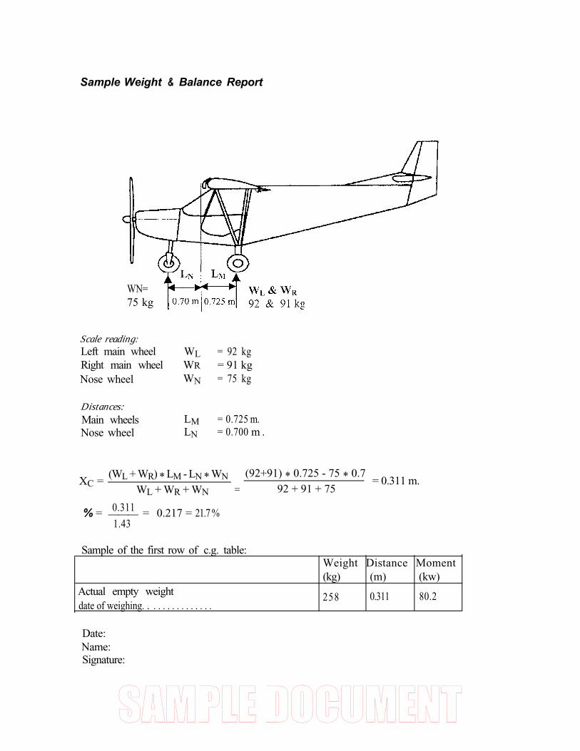
Sample Weight & Balance Report
WN=75 kg
Scale reading:Left main wheelRight main wheelNose wheel
Distances:Main wheelsNose wheel
WL = 92 kgWR = 91 kgWN = 75 kg
LM = 0.725 m.LN = 0.700 m .
XC =(WL + WR) * LM - LN * WN
=
(92+91) * 0.725 - 75 * 0.7 = 0.311 m.
WL + WR + WN 92 + 91 + 75
0.311% = ___ = 0.217 = 21.7 %1.43
Sample of the first row of c.g. table:
Actual empty weightdate of weighing. . . . . . . . . . . . . . .
Weight Distance Moment(kg) (m) (kw)
258 0.311 80.2
Date:Name:Signature:

������������
7. Aircraft and systems description
This section provides description and operation of the aeroplane and its system.
The STOL CH 701 aircraft design conforms to TP 10141 Design Standards for advancedUltra-light Aeroplanes (AULA) (Canada) and BCAR Section S (UK).
Construction:All-metal construction, stressed skin, single curvature metal skins riveted to stiffeners.
Airframe:Construction is of 6061-T6 aluminium sheet metal riveted to aluminium angles withAvex rivets. This high strength aluminium alloy construction provides long life and lowmaintenance costs thanks to its durability and corrosion resistance characteristics.
Wings:The wing has a high lift airfoil with full-span fixed leading edge slats (bolted to the wing’sleading edge) “Junker” type (separate airfoil) full-span trailing edge flaperons (combinationflaps & ailerons) and Hoerner wing tips to maximize the STOL CH 701’s effectivewingspan.
Flight Contro/s:The STOL CH 701 is equipped with a dual flight control stick between the pilot andpassenger which branches in the form of a convenient Y handle. The classic rudder pedals,connected to a large-diameter steerable nose wheel for easy of ground handling, areequipped with toe-brake hydraulic pedals on the pilot side (on both sides on option) foreffective ground steering. The vertical tail is all moving to provide maximum crosswindcapabilities. The trim-control on the elevator is electrically operated from the switch oncontrol stck)The Flap control operates the full span flaperons, it it located on the floor, pilot’s side. Toextend flaps, lift handle and move forward to the provided notch. Maximum permissibleflaps extended speed is 55 kt.
Instrument panel:Instrument panel is situated in front of pilot and includes instruments for control of theflight and engine. The aeroplane is fitted al least with those instruments:Control of flight an airspeed indicator
an altimetera magnetic direction indicatorslip indicator (ball)
control of engine rpm indicatora fuel quantity indicator

������������
a fuel quantity indicator for each tankan oil pressure indicatoran oil temperature indicatora cylinder head temperaturea coolant temperaturean oil quantity indicator - dipstick - located in the engine compartment
The equipment listed above is based on JAR-VLA and exceeds the requirements of BCARSection S.Additional instruments may be installed.
Engine controls:Dual throttles of the push/pull type with adjustable friction clamp. Springs are added tothe throttle push rods to ensure that the engine will go to full power if the linkages fail. Ifthe friction clamp is loose, this tends to result in self-application of power unless the pilotkeeps constant aft pressure on the throttle. The friction clamp, located forward of thefirewall, may be tightened or loosened.Choke: The choke is located near the pilot’s throttle (push/pull) control.Carb heat is automatic (supplied by the exhaust manifold under the cowl) for the Rotax 912when equipped with the Zenair exhaust and fiberglass cowl. See engine manual or consultengine manufacturer for details.Master switch connects the electrical system to the 12 Volt battery and charger/coil,controlled by the regulator and a 15 amp reset breaker for safety. See Engine manual forelectrical system details.Note: Engine will run with master off and/or breaker out, (the lighting and ignition coilsare two separate circuits) but no electric equipment will operate
Ignition key (or switch) must be ON to operate the engine. For safety remove key whenengine is not running.Starter button (or key) is also located near pilot’s throttle control.Note: All switches and or engine controls are "up" or “push forward” for operation, except thechoke which is “pull” for “on”.Optional equipment, switches and/or fuses are subject to change or installed as requested. SeeEquipment list.The battery is mounted in the rear fuselage with Rotax 912 powerplant installation.
Powerplant:
Standard powerplant is Rotax 912, 4-cylinder, 4-stroke, w/opposed cylinders. Refer to enginemanual for detailed description of the engine.
Fuel system:The fuel tank(s) are welded aluminium. The standard fuel system consist of one fuel tanksituated between the fire wall and instrument panel. There is also possibility of installing awing tanks.Tanks capacity:Standard . . . . . . . . . . . 42 litersOptional - “D” tank . . . . . . . 22 liter - “D” tank is approx. half size and allows to morespace between fuel tank and instrument panel (e.g for installing deeper avionics)

������������
The fuel tank filler caps have vent holes. The drain valve is situated on the gascolator,forward bottom of firewall.the tanks have a fingerscreen filter. The main fuel shut-off valve islocated at the center of aircraft above the rudder pedals.Note: Fuel shut-off valves are open when valve handles are in line with the fuel lines.The main tank (std or “D”) has a visual fuel gauge located on the passenger’s side of theinstrument panel. Caution fuel management requires a visual check of the fuel quantity usinga graduated dip stick. Electrical fuel gauge may be used.The fuel pump is mechanically operated on Rotax 912 powerplant. See engine manual fordetails. An electric fuel pump and/or fuel pressure gauge is optional.Rotas engines are equipped with dual carburetors. Each carburetor has a sediment bowlwith an additional fuel strainer (fine mesh filter). See engine manual.Caution: Consult the engine manual for the types of fuel and oil to use. Use only typesapproved by the engine manufacturer.The engine is mounted within the sleek cowlings and provides easy access via Dzus fastenersfor pre-flight inspection. The Radiator is mounted bellow the firewall in the direct airflow tomaximize cooling in hot operating environments.
Propeller:Ground adjustable two or three blade wood (or composite) propeller (diam. 1700 mm withstandard spinner. Your propeller has been set to provide optimum performances, but you canchange the pitch to achieve better climbing or cruising performances. Always refer topropeller manual for instructions!To prevent vibration, it very important that all the blades are set at exactly the same angle andthat the blades are properly secured in the hub.For a take-off and climb propeller setting angle be reduced by l/4 to l/2 degree. and for acruise propeller setting increase angle approximately by l/4 degree. Note that whencruising setting is used, the take-off and climb performance deteriorate.
Landing Gear:The main gear cons is t of a solid monoleaf heat-treated aluminum alloy springsuspension which eliminates all moving parts and is virtually maintenance free. The nosegear uses a heavy duty bungee shock absorber to provide rough field capabilities. HeavyDuty Wheel Forks are available as an option. They consist of a double over the standardwheel forks to add additional lateral stiffness.
Cabin doors:Access to the comfortable cabin is via large hinged doors on each side to provide easyindividual entrance. They are secured by two forward folding hinges and a rear upperlocking mechanism. For flight, doors may be removed if desired. Doors with an openingwindow are optional.
Seats:Side-by-side seating. Seat cushions are removable for cleaning and drying. Seatbelts aresecured to the airframe by a 4-point system.Note: Prior to each flight, ensure that the seat belts are firmly secured to the airframe andthat the belts are not damaged. Adjust the buckle so that it is centered on the body.

������������
Ventilation is provided by the standard gap at the top of each door frame. This may be sealedin cold weather. Optional vents may be added. Exhaust type cabin heater is an option wherefresh air is heated by an exhaust shroud and ducted to the pilot’s feet (pull “choke-type” control for heat).Caution: Incidents involving exhaust gases entering the heating or ventilation system mayresult in fatal accidents due to carbon monoxide poisoning of the aircraft occupants.
Pitot and static pressure sys terns:The Pitot (dynamic) pressure is provided by the pitot tube on the right hand forward strut.(Note: blowing into the tube will damage the airspeed indicator). The static pressure isprovided by the cabin pressure.
The Baggage Compartmentis the inner space provided behind the seat. It may accommodate up to 18 kg of evenlydistributed and properly secured cargo. When loading baggage, make sure that weight andbalance is correct - always refer to section 6 - Weight&balance
Cabin dimensions.
Optional equipmentUtility Options such as skis, floats, amphibious floats, etc. are available from Zenair for avariety of uses.Caution: The installation of skis floats, amphibious floats, or other equipment will changethe performance and characteristics of the STOL CH 701. The pilot must obtain properinstruction (or endorsements) prior to flying to flying the aircraft with such equipment andassure that such equipment is properly installed to the aircraft.
Note: According to regulation, the airplane must have a fireproof identification plate fixedto the airframe and have the proper registration markings. Make sure that all required
. documents are carried on board the aircraft, including this manual, the engine manual, andthe Statement of conformity issued by the manufacturer.

������������
8. Aircraft handling, servicing and maintenance
This section contains factory-recommended procedures for proper ground handling andservicing of the aeroplane. It also identifies certain inspection and maintenance requirementwhich must be followed if the aeroplane is to retain that new-plane performance anddependability. It is wise to follow a planned schedule of lubrication and preventivemaintenance based on climatic and flying conditions encountered.
Always handle the aircraft with care. Do not push on any control surface (this includes thestabilizer). To push the tail down, lift the prop hub or push down on the rear fuselage. Tomove the aircraft, do not push or pull at the centre of the struts, as bent struts areinappropriate for safe flying. Pushing or pulling is acceptable on the gear and at thebottom and top of the struts (close to their attachment points). In all circumstances, follow allsafety precautions pertaining to aircraft, especially around the propeller area.As the STOL CH 701 is an all metal aircraft built from high strength aviation gradealuminium alloys which have good corrosion resistant characteristics, little care to theairframe is required, especially when stored outside. Polyurethane paint will keep its highgloss for many years when sponged with water. A cup of dishwater liquid in a pail of waterwill help remove unwanted dirt. Always rinse thoroughly with fresh water after washing.
Maintenance program
The following maintenance program outlines the minimal maintenance which must befollowed to keep the aircraft in good flying condition. The suggested time interval of 25hour does not in any sense eliminate the need for routine maintenance before and after eachflight. Maintenance is part of the pilot’s responsibility: the pilot should be assured that theaircraft is airworthy at all times. The recommended 25 and 100 hour maintenance checksare designed to cover areas frequently neglected in the quicker preflight inspection andserve only as a useful indication of the required maintenance. Record all maintenance andrepairs in the Aircraft Log Book.Aircraft servicing and maintenance should be performed by a qualified individual. Forspare or replacement airframe parts, use genuine Zenair parts to quarantee long life anddurability. Use only genuine engine manufacturer parts on the engine.Contact your Zenair dealer or manufacturer for all your service, maintenance and partsrequirements.For Zenair factory technical support or to order parts:
Czech Aircraft Works s.r.o.Osvobozeni 527687 09 BorsiceCzech Republicphone:+420-632-501 013fax: +420 - 632 - 501 429email: [email protected]

������������
Every 25 hoursCheck the general condition of the STOL CH 701 and in particular the following:
General: Verify that no cables are chafed, check for proper anchorage and attachmentof all items (fuel, coolant, and oil lines, electrics etc). Verify that all fasteners and pins havethe required safety.Controls: Check for rust on steel parts (clean and repaint as required). Lubricate allmoving parts (hinges, control attachments, bearings, etc). Verify that all controls operatesmoothly and that they are firmly attached.Landing gear: inspect nose gear, stops, bangee, control and inspect the main spring, wheelforks and axles.Wheels: for correct tire pressure see picture. Checkthe tire wear, rims, and braking system and lines.Cabin interior: Clean with household cleanersaccording to the materials. Soap or detergent andwater is not recommended for cleaning theupholstery since they could remove some of fireretardant with which the seats may have beentreated.
3/4
Windshield and windows: The windshield is asingle piece of polycarbonate plastic, highly resistant to impact. Clean with “Windex” asthe polycarbonate will craze with most chemicals. Do not use gasoline, alcohol, oil,lacquer, benzene, paint thinner, etc..... The optional protective windshield cover will protectit from dust, sand and curious onlookers.Battery: Check fluid level, especially in hot water. Maintain the level at the top level markby adding distilled water as required (read instructions located on battery). Do not overfill asspillage may corrode the airframe.Propeller: Wood propellers are inexpensive and dampen vibrations efficiently, butmaintenance is required to keep the propeller in proper condition. The prop may needperiodic revarnishing. Check the tips and leading edges for damage. Look for nicks andcracks. Inspect spinner, bolts (tight and secured). Wiping the propeller with an oily clothwill result in cleaning off grass and bug, stains. Do not operate airplane in rain since thewood propeller will get damaged.Engine compartment: Thoroughly check and inspect the engine compartment, includingthe reduction gear unit, exhaust system, fuel system, oil system and coolant system.Remove and clean the carburetor bowls. Clean (replace if required) the carburetor air filter.The engine and compartment should be kept free of any accumulation of oil, grassm anddirt to prevent a fire hazard. See Engine manual for more information.Engine: Refer to engine manual - follow the recommended procedure by enginemanufacturer.Engine cowling: Check for looseness, Dzus fasteners, front pins and any damage or cracks.Make sure it is properly secured.Fuel: Remove, clean, and re-install gascolator. Inspect for any leaks and loose fittings inthe lines and tank(s), and assure the smooth operation of shut-off valves. Clean (orreplace) any installed filters.

������������
Every 100 hour or six months (whichever comes first)Clean the aircraft: exterior and interior and remove the rear fuselage bottom access door.Make a thorough inspection of the whole aircraft, inspecting for any damage, wear orcorrosion.
Front of aircraft: Check and inspect the following: Engine (see engine manual), controlsand hoses, engine mount, propeller, battery, exhaust, radiator, firewall, nose gear andwheel. Check that all bolts and nuts are tight and safetied.Fuel system: Check for leaks, check condition and safety of lines and valve operation.Clean, re-install (or replace) and secure all filters, gascolator and tank finger screen.Fuselage: Check skins and internal structure for loose rivets, bolts, corrosion andbuckling due to miss-handling or over-stressing. Check that the drain holes in thebottom of the fuselage are not plugged up.Controls: Inspect for looseness, wear, fair-leads and terminals.Wing & Struts: Check skins, replace loose rivets, check for corrosion and buckles (frommishandling), inspect leading edges and tralling edges. Check bolts and safety (struts, jurystruts, wing root attachments, slats and flaperons). Check control surface stops and flaperoninterconnection.Tail: Inspect skins and rivets and look for and correct corrosion etc. Check attachment oftail sections to fuselage, cable ends, trim tab, etc. Check control surface stops.Landing gear: Refer to 25 hour check list
After the thorough inspection of the aircraft, and after having done the requiredmaintenance and/or repairs, re-install the rear fuselage access door and run the engine forsmooth operation. Check all control hinges and moving parts for wear. Replace whenclearance exceeds maximum wear of 0.6 mm.
Oil the following (standard “motor” oil):
all bearingsall flaperon hinge pointsall flaperon control rods *roll control torque tubeelevator and trim (trim + control)all rudder hinge pointsall elevator bellcranks *flaperon mixer *all pitch control rod ends *all control stick bearings (in cabin)pedals (3 bearings, cable ends, brake pedals)flaperon and trim controlsall cable ends (also *)all throttle bearingschoke control (if applicable)all door hinges and latch
* inside fuselage - access through fuselage door.

������������
Grease (with ball bearing grease): the nose gear strut (top and bottom bearing) and nosewheel axle, and grease all cable fairleads.Main gear spring attachment.. Check that the rubber pads are undamaged and properlysecured in place (check top and bottom, right and left sides).After having made a hard landing: Check the wheel forks (especially if landing was incroswind), they may be bent sideways. Check the main gear spring, forks, wheels, nose gearstrut attachments top and bottom.
Note: If an unusual fact is discovered at any time, during pre-flight or at scheduledinspections, contact a Zenair dealer or the manufacturer for the proper maintenanceprocedure. DO NOT attempt to maintain or repair the aircraft without properqualifications. ALWAYS refer to the STOL CH 701 Plans and Manuals, end Enginemanual(s) before effecting repairs or replacing parts. ALWAYS use approved replacementparts.
Rivet replacement: Drill out loose or corroded blind rivets and replace using Avex rivets.If required, replace with a rivet the next size up. and/or add another rivet at approximately12 mm center distance.Caution: do not damage internal structure when drilling.Cracked sheet metal: If a small crack appears, stop the crack by drilling a small (3.2 mm)hole at the end of crack. If crack grown again add a patch of the same thickness materialand rivet all around with AVEX A4 rivets at a maximum pitch of 40 mm. Do not damageinternal structure when drilling.Buckled trailing edges (due to mishandling): They are usually net detrimental to thestrength of the aircraft. as long as the buckle does not exceed 15 mm over 1 m. They mayslightly off-set the correct trimming in flight. Check for cracks which may develop.

������������
9. Supplements

������������
Ins talled Equipment / Option List
Aircraft serial No:Powerplant:
Registration No:Serial No.
I Propeller: Fuel system:
The following is a list of installed options or specialized equipment not normally equippedstandard CH 701. See drawing and manuals for standard equipment.
Description (Part #) Install date