zero turn radius report - team panache (1)
TRANSCRIPT

JOHN DEERE TECHNOCHAMP ZERO/MINIMUM TURNING RADIUS TEAM PANACHE
1
ZERO/MINIMUM TURNING RADIUS
Objective:
The vehicle that we have selected as our baseline vehicle is a John Deere 5065 E tractor. Our objective is to enable the
tractor to turn with a minimum or preferably zero turning radius. This should be achieved:
1. Without over-complicating the design.
2. By making a design that is realistic & technically feasible.
3. By making a design which is cost effective.
4. Trying to facilitate fail-safes or poke-yoke concepts so as to help users adjust to the new design/model.
What do we mean by “minimum turning radius” or “zero turn”?
A zero turn if taken literally means that the tractor should be able to rotate about a stationary pivot point/axis. A
minimum turn radius means that the turn envelope of the tractor should be as small as could possibly be achieved. In
other words the minimum wall to wall distance within which the vehicle can turn should be as small as possible.
Baseline Vehicle Specifications:
A photo of the John Deere 5065 E

JOHN DEERE TECHNOCHAMP ZERO/MINIMUM TURNING RADIUS TEAM PANACHE
2
NOTE:
All the details furnished below are freely available on John Deere’s website and none of the information is subject to
plagiarism.
Manufacturer: John Deere
Model: 5065 E
Key Specifications:
Engine:
Power: 65 hp
Max Speed: 2400 rpm
Miscellaneous Details: 3 Cylinders, Rotary FIP, Coolant cooled with overflow reservoir, Turbo charged
Air - Filter: Dry type, Dual element
Transmission:
Clutch: Dual
Gear Box: 9 Forward + 3 Reverse, Collar shift
Brakes:
Self-Adjusting, Self-equalizing, Hydraulically Actuated oil immersed disc brakes
Hydraulics:
Lifting Capacity: 1800 kgf
3 Point Linkage: Category II
Automatic Depth & Draft Control
Steering:
Type: Power Steering
Steering Column: Tiltable upto 25 degree with lock latch
Front Axle:
Heavy duty variable track
Power Take Off:
Type: Independent, 6 Splines
Standard: 540 @ 2376 ERPM
Economy: 540 @ 1705 ERPM
Wheels and Tires:
Front Width: 6.5 inch
Front tire outer Diameter: 25 (assumed) inch
Rear Width: 18.4 inch
Rear tire outer Diameter: 50 (assumed) inch
Fuel Tank Capacity:
68 litres
Electrical System:
100 Ah, 12 Volt Battery, 40 Amp. Alternator, 12 Volt
2.5 kW Starter Motor
Dimensions and Weight:
Total Weight: 2290 kg
Wheel Base: 2035 mm
Overall Length: 3535 mm
Overall Width: 1890 mm
Ground Clearance: 510 mm
Turning radius with brakes: 3099 mm
Baseline Vehicle Specifications

JOHN DEERE TECHNOCHAMP ZERO/MINIMUM TURNING RADIUS TEAM PANACHE
3
Some important point to remember:
Engine max. power: 65hp @ 2400 rpm
Steering type: power steering
Rear tire outer diameter: 50 inch
Total Weight: 2290 kg
Wheel Base: 2035 mm
Overall length: 3535 mm
Overall width: 1890 mm
Turning Radius with brakes: 3099 mm
Tractors take sharp turns with brake assistance. That means if a tractor is to turn left the driver can press the left brake
to reduce the speed of the left drive wheel while the right wheel continues to move undisturbed. The same can be
done for right turns. This independent braking system enables the tractor to take sharp turns.
Our aim would be to try and reduce this turning radius as far as possible.
Since the tractor has a power steering system we do not want to eliminate this feature unless we are implementing a
better steering option.
We have assumed the peripheral diameter of both tires since this data wasn’t available on John Deere’s Website. For
The front tire we have considered a peripheral diameter of 25” and for the rear 50”.
We have also considered the weight distribution about the center of gravity to be in a 40/60 ratio. In other words, 40%
of the weight acts on the front axle & 60% of the weight acts on the rear axle.
Solution:
The means by which we wish to achieve our goal is by the extensive use of hydraulics. Please refer to the diagram on
following page.
In our design we eliminate the gear box transmission & differential of the tractor as well as its conventional braking
system by incorporating both of these systems in the hydraulic circuit. The reason for doing this is due to the fact that
the two independent hydraulic motors enable the wheels to rotate not only in the same direction (for forward or
reverse) but also in opposite direction (for zero turning). This is analogous with the way an army tank turns. This
solution is similar to the John Deere “Skid Steer” however we try to eliminate the “skid” as in some cases it may induce
heavy stresses onto the drive axles.
In our design, regular steering is achieved by means of the power steering unit. We do not intend to change the power
steering that is already present, however we do wish to introduce hydraulic tie-rods connecting the ends of the
steering rods to the ends of the steering arms. Thus in our design we have also calculated the power and pressure
required for hydraulic steering unit. The force on the steering rod will also be the force that the tie rods will be
subjected to considering the same pressure in both the tie-rods as well as the double acting steering rod.
The engine (prime mover) is connected rigidly to a heavy duty axial piston pump. The pump receives fluid from the
reservoir via a suction strainer. The fluid is pressurized to 4500 PSI. This fluid gets split, such that some of it goes to
the steering unit. The rest is used either for the zero turning tie rods or the Hydrostatic transmission, (both of which
are never to be actuated simultaneously).
The pressure in the steering circuit as well as the zero turn tie rod’s circuit, is limited to 1000 PSI, whereas the pressure
in the HST circuit is 4500 PSI. Thus 4 pressure relief valves must be used so as to enable the use of multiple pressures.

JOHN DEERE TECHNOCHAMP ZERO/MINIMUM TURNING RADIUS TEAM PANACHE
4
Overview of Hydraulic Circuit
PUMP
SUCTION
STRAINER
PRV 2
PRV 3
FLOW
COMPENSATOR
LEFT MOTOR RIGHT MOTOR
LEFT REAR TIRE RIGHT REAR TIRE
DCV 1
DCV 2 DCV 3
PSU
STEERING
ACTUATOR
LEFT TIE ROD RIGHT TIE ROD
FRONT
LEFT
TIRE
FRONT
RIGHT
TIRE
PRV 1
PRV 4
RESERVOIR

JOHN DEERE TECHNOCHAMP ZERO/MINIMUM TURNING RADIUS TEAM PANACHE
5
The pump is a heavy duty axial piston pump selected from an Eaton catalog. Its details are provided in the coming
section. The motors are also axial piston heavy duty types.
DCV – Direction Control Valve – these are provided in order to change or reverse the direction of flow of fluid in the
circuit.
DCV 1: This prevents the simultaneous operation of the drive wheels and the extension of the turn tie rods into zero
turn position. It helps extend and retract the tie rods. When it is in center position the rods get hydraulically locked
and all the fluid being pumped is directed towards the drive wheel motors.
DCV 2 & 3: These DCVs control the direction in which the motors rotate (forward & reverse) and can also be used for
braking purposes (in the center position).
PRV – Pressure Relief Valve – these are used to maintain the correct pressure in the circuit. There are four PRVs in the
circuit. This is due to the fact that the steering and zero turning circuits uses 1000 PSI whereas the HST uses 4500 PSI.
Correct pressure must be supplied in order for efficient performance and to prevent damage of components.
Since the pump pressurizes the fluid to 4500 PSI, PRV 1, 2 & 3 limits the pressure to 1000 PSI. PRV 4 only comes into
use if the pressure exceeds 4500 PSI and maintains this pressure being supplied to the motors.
PSU – Power Steering Unit- this is a component that already exists in the baseline vehicle however since its data isn’t
provided we needed to provide some calculations to represent the steering unit. The PSU in the above circuit is being
represented by a DCV however it should not be mistaken for an actual DCV. A more detailed explanation of this device
is provided in coming section. The PSU is connected to the double actuating cylinder which is used for regular steering
conditions.
The double acting cylinder is attached to the hydraulic tie rods. When these actuate we get the zero turning position
of the front wheels.
Flow compensator – This device behaves analogous to a differential. When less flow is required in one tire and more
in the other during turning it increases the flow to one motor and compensates the same amount from the other.
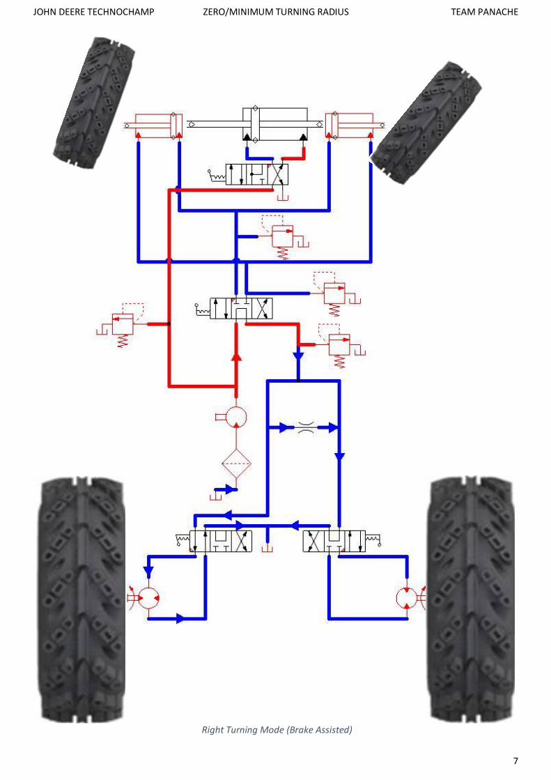
Regular Turning:
The regular turning of the tractor can be achieved with the power steering unit. The variation in speed and torque
required by the wheels on the inside and outside of the turn can be assisted with the flow compensator.
For tight turns, normally a tractor can brake one wheel. So as to not eliminate this feature of its maneuverability the
DCVs 2 & 3 are provided with a center position in which the fluid can directly return to the reservoir and at the same
time the driving motor can be stalled thus seizing the corresponding wheel.
For example for a tight left turn, the left motor’s DCV (DCV 2) is put into hydraulic locking position, whereas the right
motor’s DCV (DCV 3) is left in forward position. For tight right turns vice-versa.

JOHN DEERE TECHNOCHAMP ZERO/MINIMUM TURNING RADIUS TEAM PANACHE
6
Left Turning Mode (Brake Assisted)
JOHN DEERE TECHNOCHAMP ZERO/MINIMUM TURNING RADIUS TEAM PANACHE
7
Right Turning Mode (Brake Assisted)

JOHN DEERE TECHNOCHAMP ZERO/MINIMUM TURNING RADIUS TEAM PANACHE
8
Zero Turning Mode
711.2mm
2035
mm
Pivot Point

JOHN DEERE TECHNOCHAMP ZERO/MINIMUM TURNING RADIUS TEAM PANACHE
9
Zero Turning Mode:
When a zero turn is required, both the cylinders can be made to extend simultaneously. The steering wheel is brought
into center position.
Thus the line drawn through the center of the wheel in the top view forms a tangent to an arc whose center coincides
with the vehicles center (exactly between rear wheels).
As the rear tires rotate in opposite directions, the tractor will be able to rotate about its center hence achieving a zero
turn. The main drawback is that this circuit is complex to design. Also more components means less reliability and
increased cost.
If we consider the pivot point as the center of the turn, then ideally the tractor would turn exactly about this point,
thus successfully achieving a zero turn. Considering the wheel base and half the wheel track the hypotenuse would
form radius to the turn envelope. This would help us understand the amount of room required for the tractor to take
a zero turn.
NOTE:
1. When the tie rods expand and retract the drive wheels need to be stationary.
2. When the tie rods have expanded the drive wheels should rotate in opposite directions. In order to achieve a
zero turn.
If the above two conditions are not satisfied there will be immense stresses on the front wheels’ axles. Thus some fool
proofing may be required with the help of electronics (logic gates, etc.). As a fail-safe to the first condition if both the
motors as well as the hydraulic tie rods are actuated simultaneously the power demand will exceed what is provided
by the engine thus, stalling the circuit before immense forces are experienced.
The tractor already is equipped with a power steering system but since no data of this system is provided we will have
to design one so as to find out the steering details/parameters/actuator specifications etc.
Hydraulic Steering Design:
Approximate kingpin torque:
We have assumed a 40/60 weight distribution, (i.e. 40% of the weight supported by front axle and 60% by rear).
Total weight of the tractor = 2290 kg
Therefore weight on the steering axle = 40% * 2290 kg = 916 kg
(or 2019.78 lbs)
Next we must determine the steering geometry:
Let E be the Kingpin Eccentricity = 6.5 inch
Let B be the tire tread width = 6.5 inch (front tires)
Hence we get an E/B ratio of 1.

JOHN DEERE TECHNOCHAMP ZERO/MINIMUM TURNING RADIUS TEAM PANACHE
10
Now from the chart of coefficient of friction vs. E/B ratio we can determine the coefficient of friction.
Method:
Once you know your E/B ratio draw a vertical line from the x axis
until it intersects with the curve. From the point of intersection,
draw a horizontal line to intersect the y axis and note the value of
coefficient of friction (f).
In our case since our E/B ratio is 1, the corresponding coefficient of
friction is 0.11 approximately.
Total kingpin torque:
𝑇 = 𝑤 ∗ 𝑓 ∗ √𝐵2
8+ 𝐸2
Where,
T = total kingpin torque required to steer axle (lb-in)
w = weight supported by steered axle (lbs.)
f = coefficient of friction
B = tire tread width (in)
E = kingpin Eccentricity (in)
∴ 𝑇 = 2019.78 ∗ 0.11 ∗ √6.52
8+ 6.52
∴ T = 1531.745 lb-in (or 173.09 Nm)
Approximate Cylinder force:
𝐶𝐹 =𝑇
𝑅
Where,
T = total kingpin torque required to steer axle: 1531.745 lb-in
R = Steering Arm Radius: 2.5 inch (63.5mm) assumed
∴ 𝐶𝐹 =1531.745
2.5
∴ CF = 612.69 lbs (or 2726N)
NOTE:
The figure on the right doesn’t show the exact actuator
arrangement that we are considering in this solution.

JOHN DEERE TECHNOCHAMP ZERO/MINIMUM TURNING RADIUS TEAM PANACHE
11
How a PSU works:
A PSU in generally seen to have 4 ports (T, P, L & R). This stands for:
T = Tank = flow return to the reservoir from this port.
P = Pump = pressurized flow enters the PSU from the pump.
L & R = Left and Right = in these ports, generally the flow can be in either direction depending on the direction in which
the steering wheel is rotated. The direction of the flow can control the way in which the vehicle is turned (either left
turn or right turn)
The connections should be such that, from a user’s perspective when the steering wheel rotates clockwise the vehicle
turns right and vice-versa.
The benefit of power steering is that the power generally comes from the pump in the form of high pressure fluid. The
human (user) only needs to provide the direction.
This is beneficial in situations where the amount of force required to steer may vary immensely. Also since the tractor
is normally used for off-road applications, it would be difficult to predict the exact coefficient of friction the vehicle
would be subjected to. Considering worst case scenarios we must make sure that the user is in control at all time. The
user should be able to steer the vehicle easily and effortlessly.
The baseline vehicle already has a power steering system however since its details aren’t available we have resorted
to designing our own power steering circuit. We have selected the Char-Lynn Series 2 PSU as it seems appropriate for
our application.
Determine the Pressure Rating of the Steering System:
Since exact details about the 5065 E are not specified we have selected Char Lynn series 2 PSU (steering control unit).
Its exact details are provided on the following page.
Typical Power Steering System

JOHN DEERE TECHNOCHAMP ZERO/MINIMUM TURNING RADIUS TEAM PANACHE
12
Specifications of the Char-Lynn Series 2 PSU

JOHN DEERE TECHNOCHAMP ZERO/MINIMUM TURNING RADIUS TEAM PANACHE
13
Steering Wheel, Steering Column & PSU Assembly
Power Steering Unit (PSU) from the outside
Power Steering Unit (PSU) from the inside

JOHN DEERE TECHNOCHAMP ZERO/MINIMUM TURNING RADIUS TEAM PANACHE
14
Thus we can operate the Steering system at a pressure of 1000 PSI (or 68.966 bar)
𝑃𝑖𝑠𝑡𝑜𝑛 𝐴𝑟𝑒𝑎 =𝐶𝑦𝑙𝑖𝑛𝑑𝑒𝑟 𝐹𝑜𝑟𝑐𝑒
𝐶𝑦𝑙𝑖𝑛𝑑𝑒𝑟 𝑃𝑟𝑒𝑠𝑠𝑢𝑟𝑒
∴ 𝑃𝑖𝑠𝑡𝑜𝑛 𝐴𝑟𝑒𝑎 =612.698 𝑙𝑏𝑠
1000 𝑃𝑆𝐼
∴ Piston Area = 0.613 in2 (or 395.29 mm2)
We notice in the steering, there are two different linear actuators:
1. The double acting cylinder for regular steering
2. The hydraulic tie rod for zero turning operations
We shall design these actuators as per our requirements and also try to model them similar to products that are
commercially available.
The main stress bearing element in these actuators which can be subject to buckling is the cylinder rod. For both, the
double acting steering actuator as well as the tie rods we shall design the cylinder and rods out of same material.
For both the actuators we shall perform a stress based analysis on Ms Excel to check permissibility as well as a strength
based analysis on Altair Hypermesh to check for maximum deflection. In both actuators the rod will be subjected to
the maximum cylinder force being applied which is 2726 N
The material we have selected is Carbon Steel C40 (hardened and tempered)
This material has an ultimate tensile stress (Sut) = 750 N/mm2
We are considering a Factor of Safety (FOS) = 5
Stress Based Analysis:
Let σper be the permissible stress that the rod can take.
𝜎𝑝𝑒𝑟 =𝑆𝑢𝑡
𝐹𝑂𝑆
∴ 𝜎𝑝𝑒𝑟 =750
5
∴ 𝜎𝑝𝑒𝑟 = 150 N/mm2
Strength Based Analysis of the steering actuator rod:
Maximum Stress: 6.573 N/mm2

JOHN DEERE TECHNOCHAMP ZERO/MINIMUM TURNING RADIUS TEAM PANACHE
15
Since the maximum stress induced in the rod (6.573 N/mm2) is less than the permissible stress (150 N/mm2), design is
safe.
The deflection found from the strength based analysis shows that the rod is subjected to a deflection to the order of
10-3 mm which is negligible.
Rod and Cylinder Diameter:
𝐴𝑟𝑒𝑎 𝑜𝑓 𝑟𝑜𝑑 =𝐶𝐹
𝜎𝑝𝑒𝑟
∴ 𝐴𝑟𝑒𝑎 𝑜𝑓 𝑟𝑜𝑑 =2726
150
∴ 𝐴𝑟𝑒𝑎 𝑜𝑓 𝑟𝑜𝑑 = 18.172 mm2
∴ Diameter of rod = 4.810 mm (minimum required)
Nominal rod diameters of linear actuators that are commercially available are 0.63 inch.
∴ Actual diameter of rod = 0.63 inch (or 16 mm)
Since this is greater than the nominal required diameter it is PERMISSIBLE.
We shall now proceed with the steering calculations and once this is done, we shall do the calculations for the Zero
turn tie rods.
We have assumed the front wheels have a wheel track of 56 inch.
Using Solid Works we can geometrically select a Double acting cylinder with a stroke length of 6 inch (or 152.4 mm).
𝑃𝑖𝑠𝑡𝑜𝑛 𝐴𝑟𝑒𝑎 =𝜋
4∗ (𝐷2 − 𝑑2)
Where,
D = bore diameter of the cylinder
d = rod diameter = 0.63 inch
Piston Area = 0.613 inch
∴ D = 1.085 inch
Maximum Deflection: 7.713 x 10⁻³ mm

JOHN DEERE TECHNOCHAMP ZERO/MINIMUM TURNING RADIUS TEAM PANACHE
16
Swept Volume (SV) (from center position to full left or right):
SV = Stroke length * Piston Area
SV = 6 * 0.613
SV = 3.678 in3
Number of turns of Steering Wheel from lock to lock:
These means how many revolutions of the steering wheel will be required to turn the front wheels from full left turn
position to a full right turn position or vice-versa.
Ideal Displacement =SV (full left to full right)
𝑖𝑑𝑒𝑎𝑙 𝑛𝑢𝑚𝑏𝑒𝑟 𝑜𝑓𝑡𝑢𝑟𝑛𝑠
Let the ideal number of turns of steering wheel (from full left to full right position) be 2.
∴ Ideal Displacement =2 ∗ 3.678
2
∴ Ideal Displacement = 3.678 in3/rev
From the Series 2 catalogue selecting the closest possible match we get 3.8 in3/rev
Actual number of turns =SV (full left to full right)
𝑎𝑐𝑡𝑢𝑎𝑙 𝑑𝑖𝑠𝑝𝑙𝑎𝑐𝑒𝑚𝑒𝑛𝑡
∴ Actual number of turns =2 ∗ 3.678
3.8
∴ Actual number of turns = 1.93 revolutions (lock to lock)
NOTE:
We notice that the steering sensitivity is directly related to the displacement of the PSU being used. In case the
sensitivity is too much another option from the Char-Lynn series 2 PSUs is 3.1 in3/rev.
Pump Flow Required by PSU:
𝐹𝑙𝑜𝑤 𝑅𝑒𝑞𝑢𝑖𝑟𝑒𝑑 =𝐴𝑐𝑡𝑢𝑎𝑙 𝐷𝑖𝑠𝑝𝑙𝑎𝑐𝑒𝑚𝑒𝑛𝑡 ∗ 𝐴𝑐𝑡𝑢𝑎𝑙 𝑁𝑢𝑚𝑏𝑒𝑟 𝑜𝑓 𝑇𝑢𝑟𝑛𝑠 (𝑙𝑜𝑐𝑘 𝑡𝑜 𝑙𝑜𝑐𝑘) ∗ 60
231
∴ 𝐹𝑙𝑜𝑤 𝑅𝑒𝑞𝑢𝑖𝑟𝑒𝑑 =𝐴𝑐𝑡𝑢𝑎𝑙 𝐷𝑖𝑠𝑝𝑙𝑎𝑐𝑒𝑚𝑒𝑛𝑡∗𝐴𝑐𝑡𝑢𝑎𝑙 𝑁𝑢𝑚𝑏𝑒𝑟 𝑜𝑓 𝑇𝑢𝑟𝑛𝑠 (𝑙𝑜𝑐𝑘 𝑡𝑜 𝑙𝑜𝑐𝑘)∗60
231
∴ 𝐹𝑙𝑜𝑤 𝑅𝑒𝑞𝑢𝑖𝑟𝑒𝑑 =3.8∗1.93∗60
231
∴ 𝐹𝑙𝑜𝑤 𝑅𝑒𝑞𝑢𝑖𝑟𝑒𝑑 = 1.91 gpm (or 7.2282 litre)
Power Demand by PSU:
𝑃𝑜𝑤𝑒𝑟 𝐷𝑒𝑚𝑎𝑛𝑑 𝑏𝑦 𝑃𝑆𝑈 =𝐹𝑙𝑜𝑤 ∗ 𝑝𝑟𝑒𝑠𝑠𝑢𝑟𝑒
1714
∴ 𝑃𝑜𝑤𝑒𝑟 𝐷𝑒𝑚𝑎𝑛𝑑 𝑏𝑦 𝑃𝑆𝑈 =1.91 ∗ 1000
1714
∴ Power Demand by PSU = 1.11 hp (or 0.8308 kW)

JOHN DEERE TECHNOCHAMP ZERO/MINIMUM TURNING RADIUS TEAM PANACHE
17
Zero Turn Hydraulic Tie Rod Design:
The rod used here is same as that used in the steering actuator. Thus stress based analysis will not change.
Considering Wheel Track = 56 inch (front wheels)
This is a line diagram showing the Zero Turning
Geometry.
From this diagram we gather that the wheels will have
to rotate by almost 750 in order to achieve zero turning
mode.
The rotation is achieved with the help of hydraulic
linear actuators or simply hydraulic tie rods.
We have considered a wheel track of 56” for the front
wheels with a King Pin eccentricity of 6.5” on either
side, thus the King Pin to King Pin distance is 43”.
The purpose of this image is to comprehend what the
stroke length of the hydraulic tie rods should be. Given
that the length comes out as 12.427” the stroke will be
half of this: 6.21” considering next largest standard
dimension we get 6.5” stroke. This does not necessarily
mean that the entire stroke length will be used. It may
be limited (if required) with the help of limit switches.
Zero Turning Geometry

JOHN DEERE TECHNOCHAMP ZERO/MINIMUM TURNING RADIUS TEAM PANACHE
18
Length of the double acting Steering actuator (end to end) = (4 * stroke length) + (2 * connector length) + (width of
piston)
∴ Total length = (4 * 6) + (2*2.5) + 1 … (in the diagram above, we have neglected the connectors)
∴ Total length = 30 inch
King Pin to King Pin distance = Wheel Track – (2* King Pin Eccentricity)
∴ King Pin to King Pin distance = 56 – (2 *6.5)
∴ King Pin to King Pin distance = 43 inch
𝐿𝑒𝑛𝑔𝑡ℎ 𝑜𝑓 𝑒𝑎𝑐ℎ 𝑡𝑖𝑒 𝑟𝑜𝑑 =𝑘𝑖𝑛𝑔 𝑝𝑖𝑛 𝑡𝑜 𝑘𝑖𝑛𝑔 𝑝𝑖𝑛 𝑑𝑖𝑠𝑡𝑎𝑛𝑐𝑒 − 𝑙𝑒𝑛𝑔𝑡ℎ 𝑜𝑓 𝑠𝑡𝑒𝑒𝑟𝑖𝑛𝑔 𝑎𝑐𝑡𝑢𝑎𝑡𝑜𝑟
2
∴ 𝐿𝑒𝑛𝑔𝑡ℎ 𝑜𝑓 𝑒𝑎𝑐ℎ 𝑡𝑖𝑒 𝑟𝑜𝑑 =43 − 30
2
∴ 𝐿𝑒𝑛𝑔𝑡ℎ 𝑜𝑓 𝑒𝑎𝑐ℎ 𝑡𝑖𝑒 𝑟𝑜𝑑 = 6.5 inch
Let the stroke length be equal length of the tie rod = 6.5 inch
Total swept volume during zero turning = 2*(cylinder area * swept volume)
∴ 𝑇𝑜𝑡𝑎𝑙 𝑠𝑤𝑒𝑝𝑡 𝑣𝑜𝑙𝑢𝑚𝑒 = 7.96 in3
𝐹𝑙𝑜𝑤 𝑑𝑒𝑚𝑎𝑛𝑑 𝑑𝑢𝑟𝑖𝑛𝑔 𝑧𝑒𝑟𝑜 𝑡𝑢𝑟𝑛𝑖𝑛𝑔 𝑚𝑜𝑑𝑒 =𝑇𝑜𝑡𝑎𝑙 𝑠𝑤𝑒𝑝𝑡 𝑣𝑜𝑙𝑢𝑚𝑒 ∗ 60
231
∴ 𝐹𝑙𝑜𝑤 𝑑𝑒𝑚𝑎𝑛𝑑 𝑑𝑢𝑟𝑖𝑛𝑔 𝑧𝑒𝑟𝑜 𝑡𝑢𝑟𝑛𝑖𝑛𝑔 𝑚𝑜𝑑𝑒 =7.96 ∗ 60
231
∴ 𝐹𝑙𝑜𝑤 𝑑𝑒𝑚𝑎𝑛𝑑 𝑑𝑢𝑟𝑖𝑛𝑔 𝑧𝑒𝑟𝑜 𝑡𝑢𝑟𝑛𝑖𝑛𝑔 𝑚𝑜𝑑𝑒 = 2.06 gpm
𝑃𝑜𝑤𝑒𝑟 𝑑𝑒𝑚𝑎𝑛𝑑 𝑑𝑢𝑟𝑖𝑛𝑔 𝑧𝑒𝑟𝑜 𝑡𝑢𝑟𝑛𝑖𝑛𝑔 𝑚𝑜𝑑𝑒 =𝑇𝑜𝑡𝑎𝑙 𝑓𝑙𝑜𝑤 ∗ 𝑃𝑟𝑒𝑠𝑠𝑢𝑟𝑒
1714
∴ 𝑃𝑜𝑤𝑒𝑟 𝑑𝑒𝑚𝑎𝑛𝑑 𝑑𝑢𝑟𝑖𝑛𝑔 𝑧𝑒𝑟𝑜 𝑡𝑢𝑟𝑛𝑖𝑛𝑔 𝑚𝑜𝑑𝑒 =2.06 ∗ 1000
1714
∴ 𝑃𝑜𝑤𝑒𝑟 𝑑𝑒𝑚𝑎𝑛𝑑 𝑑𝑢𝑟𝑖𝑛𝑔 𝑧𝑒𝑟𝑜 𝑡𝑢𝑟𝑛𝑖𝑛𝑔 𝑚𝑜𝑑𝑒 = 1.2 ℎ𝑝 (or 0.9 kW)
Cylinder Design (assuming thin cylinder):
Internal Pressure (Pi) = 1000 PSI (or 6.895 N/mm2)
Bore Diameter (di) = 1.085 inch (or 27.55mm) (same as steering actuator)
Allowable Stress (σt) = 150 N/mm2 (same material as rod)
Joint efficiency (η) = 0.5
Corrosion Allowance (CA) = 3 mm
∴ 𝐶𝑦𝑙𝑖𝑛𝑑𝑒𝑟 𝑊𝑎𝑙𝑙 𝑡ℎ𝑖𝑐𝑘𝑛𝑒𝑠𝑠 (𝑡) =𝑃𝑖 ∗ 𝑑𝑖
2 ∗ σt ∗ η+ 𝐶𝐴
∴ 𝐶𝑦𝑙𝑖𝑛𝑑𝑒𝑟 𝑊𝑎𝑙𝑙 𝑡ℎ𝑖𝑐𝑘𝑛𝑒𝑠𝑠 (𝑡) =6.895 ∗ 27.55
2 ∗ 150 ∗ 0.5+ 3
∴ 𝐶𝑦𝑙𝑖𝑛𝑑𝑒𝑟 𝑊𝑎𝑙𝑙 𝑡ℎ𝑖𝑐𝑘𝑛𝑒𝑠𝑠 (𝑡) = 4.266 mm or 5mm (rounding up)
Therefore the cylinder wall should be 5 mm thick including corrosion allowance.

JOHN DEERE TECHNOCHAMP ZERO/MINIMUM TURNING RADIUS TEAM PANACHE
19
Strength Based Analysis of the hydraulic tie rod:
Since the maximum stress induced in the rod (6.593 N/mm2) is less than the permissible stress (150 N/mm2), design is
safe.
The deflection found from the strength based analysis shows that the rod is subjected to a deflection to the order of
10-3 mm which is negligible.
Maximum Stress: 6.593 N/mm2
Maximum Deflection: 2.889 x 10⁻³ mm

JOHN DEERE TECHNOCHAMP ZERO/MINIMUM TURNING RADIUS TEAM PANACHE
20
HST Sizing:
Sr. no. INPUT PARAMETER VALUE
1
2
3
4
5
6
7
8
9
10
Mass of vehicle (kg)
Coefficient of drag resistance
Coefficient of rolling resistance
Density of air (kg/m3)
Frontal Area (m2)
Relief value pressure
Vehicle speed (kmph)
Wheel radius (m)
Engine max. speed (rpm)
Engine power (kW) at 2400 rpm
2290
0.7
0.05
1.225
1.3676
4500 PSI (310.344 bar)
70
0.635
2400
48.471
Table of constants considered for HST calculations
Prop-shaft (motor output shaft) rpm when vehicle speed is 70 kmph is given by: =𝑉𝑒ℎ𝑖𝑐𝑙𝑒 𝑠𝑝𝑒𝑒𝑑∗60
𝑊ℎ𝑒𝑒𝑙 𝑟𝑎𝑑𝑖𝑢𝑠∗3.6∗2𝜋
= 70∗60
0.635∗3.6 2𝜋
= 292.41 rpm
Theoretical size of motor is set to 6.858 in3/rev (or 118.01 cc)
Motor efficiency is 90%
∴ Actual motor size = 𝑇ℎ𝑒𝑜𝑟𝑖𝑡𝑖𝑐𝑎𝑙 𝑠𝑖𝑧𝑒
𝑒𝑓𝑓𝑖𝑐𝑖𝑒𝑛𝑐𝑦
= 6.858
0.9
= 7.62in3/rev (or 124.892 cc)
Flow demanded by motors = 2* 𝐴𝑐𝑡𝑢𝑎𝑙 𝑚𝑜𝑡𝑜𝑟 𝑠𝑖𝑧𝑒∗𝑝𝑟𝑜𝑝𝑠ℎ𝑎𝑓𝑡 𝑟𝑝𝑚
231∗𝑚𝑜𝑡𝑜𝑟 𝑒𝑓𝑓𝑖𝑐𝑖𝑒𝑛𝑐𝑦
= 2* 7.62∗292.41
231∗0.9
= 21.434gpm
Total flow demand = flow demand by motors + flow to steering actuator
Total flow demand from pump = 21.34 + 1.91
Total flow from pump= 23.34 gpm
Theoretical displacement of pump = 𝐹𝑙𝑜𝑤 𝐷𝑒𝑚𝑎𝑛𝑑 𝑏𝑦 𝑚𝑜𝑡𝑜𝑟∗231
𝐸𝑛𝑔𝑖𝑛𝑒 𝑆𝑝𝑒𝑒𝑑
∴ Theoretical displacement of pump = 23.34∗231
2400 = 2.246 in3/rev
∴ Actual displacement of pump = 2.246
0.9 = 2.496 in3/rev
Power demanded by pump = 𝐹𝑙𝑜𝑤 𝑑𝑒𝑚𝑎𝑛𝑑𝑒𝑑 𝑏𝑦 𝑚𝑜𝑡𝑜𝑟∗𝑟𝑒𝑙𝑖𝑒𝑓 𝑝𝑟𝑒𝑠𝑠𝑢𝑟𝑒
1714
= 23.34∗4500
1714
= 61.29 hp (or 45.704 kW)
Power demand by motor = 2* 𝑅𝑒𝑙𝑖𝑒𝑓 𝑝𝑟𝑒𝑠𝑠𝑢𝑟𝑒∗𝐴𝑐𝑡𝑢𝑎𝑙 𝑚𝑜𝑡𝑜𝑟 𝑠𝑖𝑧𝑒∗𝑝𝑟𝑜𝑝𝑠ℎ𝑎𝑓𝑡 𝑟𝑝𝑚
2 𝜋∗63025

JOHN DEERE TECHNOCHAMP ZERO/MINIMUM TURNING RADIUS TEAM PANACHE
21
= 2* 4500∗7.62∗292.41
2 𝜋∗63025
= 50.64 hp (or 37.7818 kW)
Torque from motor = 𝑟𝑒𝑙𝑖𝑒𝑓 𝑝𝑟𝑒𝑠𝑠𝑢𝑟𝑒∗𝑎𝑐𝑡𝑢𝑎𝑙 𝑚𝑜𝑡𝑜𝑟 𝑠𝑖𝑧𝑒
2 𝜋
= 4500∗7.62
2 𝜋
= 5460.19 lb-in (or 617.002 Nm)
Torque at wheel = Torque from motor
= 5460.19 lb-in (or 617.002 Nm)
Sizing Summary:
AXIAL PISTON PUMP EATON HEAVY DUTY - MODEL 46
Displacement min. VD 2.49 in3/rev
Displacement max. VD 1.32 in3/rev
Volumetric Efficiency ηpv 90.00% %
Hydraulic Pump Sizing
AXIAL PISTON MOTOR EATON HEAVY DUTY - MODEL 76
Displacement VD 7.62 in3/rev
Volumetric Efficiency ηmv 90.00% %
Mechanical Efficiency ηmm 90.00% %
Hydraulic Motor Sizing
Max. Flow Rate 23.34 gpm
Max. Speed 292.4107 rpm
Max. Motor Speed and Max. Flow Rate
System Pressure: 4500 PSI
Inertia of Vehicle: 6000 kgm2
Inertia of Motors: 40.214 kgm2

JOHN DEERE TECHNOCHAMP ZERO/MINIMUM TURNING RADIUS TEAM PANACHE
22
HST Calculations:
Now engine is coupled to pump in this system. Assuming there are no losses
∴ Engine speed = Pump speed
∴ When engine speed is 1200 rpm
Pump speed = 1200 rpm
∴ Flow by pump QTH = 𝑝𝑢𝑚𝑝 𝑟𝑝𝑚∗𝑝𝑢𝑚𝑝 𝑑𝑖𝑠𝑝𝑙𝑎𝑐𝑒𝑚𝑒𝑛𝑡
231
= 1200∗2.49
231
= 12.969 gpm
Flow in 1 motor = (𝑝𝑢𝑚𝑝 𝑑𝑖𝑠𝑐ℎ𝑎𝑟𝑔𝑒∗𝑝𝑢𝑚𝑝 𝑒𝑓𝑓𝑖𝑐𝑖𝑒𝑛𝑐𝑦)−(𝑑𝑖𝑠𝑐ℎ𝑎𝑟𝑔𝑒 𝑓𝑜𝑟 ℎ𝑦𝑑𝑟𝑎𝑢𝑙𝑖𝑐 𝑠𝑡𝑒𝑒𝑟𝑖𝑛𝑔)
2
= 12.969 −1.91
2
= 5.525 gpm
Motor output speed = 𝑓𝑙𝑜𝑤 𝑖𝑛 𝑚𝑜𝑡𝑜𝑟∗ 231
𝑑𝑖𝑠𝑝𝑙𝑎𝑐𝑒𝑚𝑒𝑛𝑡 𝑜𝑓 𝑚𝑜𝑡𝑜𝑟
= 5.525 ∗231
8
= 159.23 rpm
Motor angular velocity = 2𝜋 𝑁
60
= 2𝜋∗159.23
60
= 16.67 rad/s
Motor torque = 𝑠𝑦𝑠𝑡𝑒𝑚 𝑝𝑟𝑒𝑠𝑠𝑢𝑟𝑒∗𝑚𝑜𝑡𝑜𝑟 𝑑𝑖𝑠𝑝𝑙𝑎𝑐𝑒𝑚𝑒𝑛𝑡∗0.113
2𝜋
= 4500∗7.62∗0.113
2𝜋
= 617.0015 Nm
Rolling resistance torque = coefficient of rolling resistance * mass of vehicle* 9.81* radius of wheel
= 0.05*2290*9.81*0.635
= 213.9781725 Nm
Now to calculate air drag we must know the speed of the vehicle. But since we are calculating velocity by net torque,
we get an equation with unknowns on both sides.
∴ Air drag torque = 𝜌
2 Cd AV2
∴ We have calculated torque assuming velocity of motor with the following empirical relation:
{Where V = k * N, taking k = 0.008}
Explanation:
We know when the engine is run at 2400 rpm we want a top speed of 70 kmph.
∴𝑉
3.6= 𝑘 ∗ 𝑁

JOHN DEERE TECHNOCHAMP ZERO/MINIMUM TURNING RADIUS TEAM PANACHE
23
∴ 𝑘 =70
3.6 ∗ 2400
∴ k = 0.008
Therefore at 1200 rpm,
∴V = 0.008 * 1200
= 9.6 m/s
∴ Air drag torque = 1.225
2 *0.7*1.3676*9.62*0.635
∴ Air drag torque = 34.13 Nm
∴ Load torque = Rolling resistance torque + Air drag torque
= 213.9781725 + 34.13
= 248.29 Nm
To find actual motor torque under loading condition
TM– TLoad = [Iv+Im](𝜔2−𝜔1)
(𝑡2−𝑡1)
Where;
TM = motor torque
TLoad = Load torque
Iv = inertia of vehicle
Im = inertia of motor
𝜔2 = final angular velocity
𝜔1 = initial angular velocity
TM – TLoad = [Iv+Im](𝜔2−𝜔1)
(𝑡2−𝑡1)
𝜔2 = { TM– TLoad } { 𝑡2−𝑡1}
[Iv+Im]+ 𝜔1
𝜔2 = [617.0015 −(248.29)]∗0.5
[6000+40.214]+ 13.89
𝜔2 = 13.89 rad/s
𝜔2 = actual motor angular velocity under loading condition
Power motor = Tmotor * 𝜔2
∴ Tmotor =37.7818∗1000
13.89
∴ Tmotor = 2719.39 Nm
JOHN DEERE TECHNOCHAMP ZERO/MINIMUM TURNING RADIUS TEAM PANACHE
24
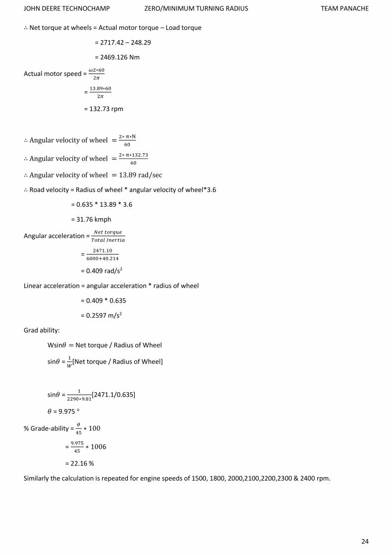
∴ Net torque at wheels = Actual motor torque – Load torque
= 2717.42 – 248.29
= 2469.126 Nm
Actual motor speed = 𝜔2∗60
2𝜋
= 13.89∗60
2𝜋
= 132.73 rpm
∴ Angular velocity of wheel =2∗ π∗N
60
∴ Angular velocity of wheel =2∗ π∗132.73
60
∴ Angular velocity of wheel = 13.89 rad/sec
∴ Road velocity = Radius of wheel * angular velocity of wheel*3.6
= 0.635 * 13.89 * 3.6
= 31.76 kmph
Angular acceleration = 𝑁𝑒𝑡 𝑡𝑜𝑟𝑞𝑢𝑒
𝑇𝑜𝑡𝑎𝑙 𝐼𝑛𝑒𝑟𝑡𝑖𝑎
= 2471.10
6000+40.214
= 0.409 rad/s2
Linear acceleration = angular acceleration * radius of wheel
= 0.409 * 0.635
= 0.2597 m/s2
Grad ability:
Wsin𝜃 = Net torque / Radius of Wheel
sin𝜃 = 1
𝑊[Net torque / Radius of Wheel]
sin𝜃 = 1
2290∗9.81[2471.1/0.635]
𝜃 = 9.975 °
% Grade-ability = 𝜃
45∗ 100
= 9.975
45∗ 1006
= 22.16 %
Similarly the calculation is repeated for engine speeds of 1500, 1800, 2000,2100,2200,2300 & 2400 rpm.

JOHN DEERE TECHNOCHAMP ZERO/MINIMUM TURNING RADIUS TEAM PANACHE
25
The entire calculation has been done on Ms Excel and the following graphs have been made to chart out the HST
system’s performance:
0
500
1000
1500
2000
2500
3000
0 20 40 60 80 100 120 140 160 180 200
Engi
ne
Spee
d (
rpm
)
Time (sec)
Engine Speed v/s Time
0
10
20
30
40
50
60
70
80
0 20 40 60 80 100 120 140 160 180 200
Ro
ad V
elo
city
(km
ph
)
Time (sec)
Velocity v/s Time
Input Signal: Engine Speed for a duration of Time
Resulting Pattern of Velocity for the same Time duration

JOHN DEERE TECHNOCHAMP ZERO/MINIMUM TURNING RADIUS TEAM PANACHE
26
0
0.1
0.2
0.3
0 20 40 60 80 100 120 140 160 180 200
Acc
eler
atio
n (m
/s2 )
Time (sec)
Acceleration v/s Time
0
5
10
15
20
25
0 10 20 30 40 50 60 70 80
Gra
dea
bili
ty %
Road Velocity (kmph)
Grade Ability v/s Road Velocity
Resulting Pattern of Acceleration for the same Time duration
Resulting Pattern of Grade-Ability for the same Time duration

JOHN DEERE TECHNOCHAMP ZERO/MINIMUM TURNING RADIUS TEAM PANACHE
27
Hydraulic Fluid Details:
Mobil DTE™ 20 Series oils are supreme performance anti-wear hydraulic oils designed to satisfy a wide range of hydraulic equipment requirements. They provide long oil/filter life and optimum equipment protection reducing both maintenance costs and product disposal costs. They were developed in conjunction with the major builders to meet the stringent requirements of severe hydraulic systems using high pressure, high output pumps as well as handling the critical requirements of other hydraulic system components such as close clearance servo valves and the high accuracy numerically controlled (NC) machine tools. These products meet the most rigorous performance requirements of a wide range of hydraulic system and component manufacturers using various multi-metallurgy designs allowing a single product with outstanding performance characteristics.
The DTE 20 Series oils are formulated with high quality base oils and a super-stabilized additive system that neutralizes the formation of corrosive materials. They are designed to work with systems operating under severe conditions where high levels of anti-wear and film strength protection are needed, yet they are formulated to work where non-anti-wear hydraulic oils are generally recommended.
Features and Benefits: The Mobil DTE 20 Series hydraulic oils provide outstanding oxidation resistance allowing extension of oil and filter change intervals. Their high level of anti-wear properties and excellent film strength characteristics result in exceptional equipment performance that not only results in fewer breakdowns but helps improve production capacity. Their detergency and keep clean properties offer service over a wide range of system cleanliness while their controlled demulsibility permits the oils to work well in systems contaminated with small amounts of water yet readily separate large amounts of water.
FEATURES ADVANTAGES & POTENTIAL BENEFITS
Anti-Wear Helps reduce wear. Protects system using various metallurgy.
Quality Reserve Maintains performance features even under severe service conditions and extended drain intervals. Helps improve system cleanliness.
Oxidation Stability Provides long oil and equipment life. Helps extend filter life.
Corrosion Protection Prevents internal hydraulic system corrosion. Helps reduce the negative effects of moisture in systems. Provides corrosion protection of multi-metallurgy component designs.
Meets a Wide Range of Equipment Requirements
One product can replace several products, minimizing inventory requirements. Helps reduce potential for product misapplication.
Air Separation Characteristics Reduces foaming potential and its negative effects.
Water Separation Protects systems where small quantities of moisture are present. Readily separates larger quantities of water.
Keep Clean Properties
Helps reduce system deposits and sludging helping to reduce maintenance costs. Protects critical components such as servo valves helping to extend equipment life. Helps improve total system performance.
Features of Hydraulic Fluid
Applications:
Hydraulic systems critical to deposit build-up such as sophisticated Numerically Controlled (NC) machines, particularly where close clearance servo-valves are used.

JOHN DEERE TECHNOCHAMP ZERO/MINIMUM TURNING RADIUS TEAM PANACHE
28
Where small amounts of water are unavoidable.
Applications where sludge and deposits form with conventional products
In systems containing gears and bearings.
Systems requiring a high degree of load-carrying capability and anti-wear protection Applications where thin oil-film corrosion protection is an asset such as systems where small amounts of water are unavoidable.
Machines employing a wide range of components using various metallurgy.
The oil we have selected for our application is SAE DTE 24. It properties are as follows:
OIL PROPERTIES
MOBIL DTE 20 Series 24
ISO GRADE 32
Viscosity, ASTM D 445
cSt @ 400C 31.5
cSt @ 1000C 5.29
Viscosity Index, ASTM D 2270 98
Specific Gravity @ 15.60C, ASTM D 1298 0.871
Pour Point, 0C, ASTM D 97 -27
Flash Point, 0C, ASTM D 92 220
SAE DTE 24 Properties

JOHN DEERE TECHNOCHAMP ZERO/MINIMUM TURNING RADIUS TEAM PANACHE
29
Reservoir Design:
Design of reservoir includes design of following components:
1 baffles 2 suction line 3 return line 4 filter cap 5 breather vent
The size and shape of reservoir is done such that dwell time should be 12 to 15 seconds. Dwell time is the time required by the fluid to move through entire circuit.
Dwell time is the ratio of oil flow through reservoir to volume of oil flow in reservoir.
∴ Dwell time = 𝑜𝑖𝑙 𝑓𝑙𝑜𝑤 𝑡ℎ𝑟𝑜𝑢𝑔ℎ 𝑟𝑒𝑠𝑒𝑟𝑣𝑜𝑖𝑟
𝑣𝑜𝑙𝑢𝑚𝑒 𝑜𝑓 𝑜𝑖𝑙 𝑖𝑛 𝑟𝑒𝑠𝑒𝑟𝑣𝑜𝑖𝑟
For 15-20 seconds dwell time the dwell ratio is:
4/1 (60/15)
3/1 (60/20)
Oil expands 35% per 100 ℉ rise in temperature or 6 % between 70℉ and 250℉. Due to water vapour minimum 10% expansion volume is included.
The discharge or flow of fluid in circuit is the product of displacement of fluid and speed of pump.
Total flow in circuit = flow to motors + flow to steering + flow to Zero turn tie rods
Total Flow = 21.34 + 1.91 + 2.06
Total Flow = 25.31 gpm
Volume of reservoir = 𝑄
4 + (0.1 *
𝑄
4 )
= 25.31
4 + (0.1 *
25.31
4 )
= 6.96 gallons (or 26.34 litres)
Now additional volumes of suction filters, valves to reservoir must be added to volume of reservoir.
Also Baffles should be below oil level to prevent turbulence.

JOHN DEERE TECHNOCHAMP ZERO/MINIMUM TURNING RADIUS TEAM PANACHE
30
Suction line design:-
Oil velocity (v) in the suction line should be maximum 4 ft. /sec (1.2192 m/s)
Area of tube or hose:
A = 𝜋𝑑2
4 = 0.321
𝑄
𝑉
d= √0.321∗𝑄 ∗4
𝜋∗𝑉
d= √0.321∗25.31 ∗4
𝜋∗4
d = 1.608 inch (or 40.8 mm)
Important Points:-
Inlet port should be located away from return line.
Return line should have diffuser to minimize turbulence. Diffuser should have nearly 40% open area of perforated material.
Filter case should be over return line with a 40 mesh screen
Breather vent at the centre of the reservoir should not be covered with oil with 40-micron filter.
Return line fluid velocity = 25 ft. /sec (7.62 m/s)
A = 0.321 𝑄
𝑉
Reservoir design

JOHN DEERE TECHNOCHAMP ZERO/MINIMUM TURNING RADIUS TEAM PANACHE
31
Suppose Open area (Ao) is 40 %
Velocity of oil is 4 ft. /sec (1.2192 m/s)
∴ 0.4 𝐴 = 0.321 𝑄
𝑉
∴ 0.4 𝐴 = 0.321 ∗25.31
25
A= 0.8124 in2
Area of tube = 𝜋 * D * L
If D = L
𝜋 D2 = 0.8124 in2
D = 0.5085 inch = 12.916 mm
Therefore length of diffuser = 0.5085 in. = 12.916 mm
Oil volume = 0.8 * volume of tank
= 0.8 * 6.96
= 5.568 gallons (or 0.021m3)
Density of Oil = 871.0 kg/m3
∴ Mass of oil = density * volume of oil
= 18.29 kg
Dimensions of tank are selected as follows:-
Breadth (b) = 30 cm
Width (w) = 30 cm
Height (h) = 29 cm
Thickness of wall (t) = 0.5 cm
Volume of the reservoir shell = {(b + 2t) * (h + 2t) * (w + 2t)} - (b*h*w)
∴ Volume of reservoir shell = {(30 + 2*0.5) * (29 + 2*0.5) * (30 + 2*0.5)} – (30*29*30)
∴ Volume of reservoir shell = 2730 cc (or 0.00273 m3)
Considering a stainless steel reservoir having density: 8000 kg/m3
Mass of reservoir shell = 0.00273 * 8000 = 21.84 kg
Weight of reservoir shell = 21.84 * 9.81 = 214.25 N
𝐻𝑒𝑖𝑔ℎ𝑡 𝑜𝑓 𝑜𝑖𝑙 𝑖𝑛 𝑟𝑒𝑠𝑒𝑟𝑣𝑜𝑖𝑟 =𝑣𝑜𝑙𝑢𝑚𝑒 𝑜𝑓 𝑜𝑖𝑙
𝑏𝑟𝑒𝑎𝑑𝑡ℎ ∗ 𝑤𝑖𝑑𝑡ℎ
∴ 𝐻𝑒𝑖𝑔ℎ𝑡 𝑜𝑓 𝑜𝑖𝑙 𝑖𝑛 𝑟𝑒𝑠𝑒𝑟𝑣𝑜𝑖𝑟 =0.021 ∗ 106
30 ∗ 30
∴ 𝐻𝑒𝑖𝑔ℎ𝑡 𝑜𝑓 𝑜𝑖𝑙 𝑖𝑛 𝑟𝑒𝑠𝑒𝑟𝑣𝑜𝑖𝑟 = 23.51 cm
Height of baffles = 70% of height of oil in reservoir
∴ Height of baffles = 16.5 cm
Let the height of the suction and return lines be 3 cm form the base of the reservoir.
JOHN DEERE TECHNOCHAMP ZERO/MINIMUM TURNING RADIUS TEAM PANACHE
32
𝑀𝑖𝑛𝑖𝑚𝑢𝑚 ℎ𝑒𝑖𝑔ℎ𝑡 𝑜𝑓 𝑜𝑖𝑙 𝑎𝑡 𝑚𝑎𝑥. 𝑡𝑖𝑙𝑡 =ℎ′
2− [
𝑏
2∗ 𝑡𝑎𝑛 𝜃]
Where,
𝜃 is the maximum grade at which the vehicle can work.
h’ is the height of oil in reservoir.
∴ 𝑀𝑖𝑛𝑖𝑚𝑢𝑚 ℎ𝑒𝑖𝑔ℎ𝑡 𝑜𝑓 𝑜𝑖𝑙 𝑎𝑡 𝑚𝑎𝑥. 𝑡𝑖𝑙𝑡 =23.51
2− [
30
2∗ 𝑡𝑎𝑛 9.97]
∴ 𝑀𝑖𝑛𝑖𝑚𝑢𝑚 ℎ𝑒𝑖𝑔ℎ𝑡 𝑜𝑓 𝑜𝑖𝑙 𝑎𝑡 𝑚𝑎𝑥. 𝑡𝑖𝑙𝑡 = 9.119 cm
Since the minimum oil height of oil at maximum tilt is greater than the height of the suction and return line, DESIGN IS PERMISSIBLE.
HOSE Selection:
The hose selection is done based on two factors:
1. Maximum Operating Pressure 2. Application
We are considering a maximum continuous operating pressure of 4500 PSI. As per our sizing calculation this is what we require to achieve a speed of 70 kmph, with power demand within rated limits.
As far as application is concerned, we require the hose to be robust so as to withstand the harsh conditions that an off-road vehicle is normally subjected to.
NOTE:
Hose Sizing has not been considered as it does not affect the performance characteristics of the transmission. For the virtue of having a complete design we have simply selected an appropriate model based on above mentioned conditions.
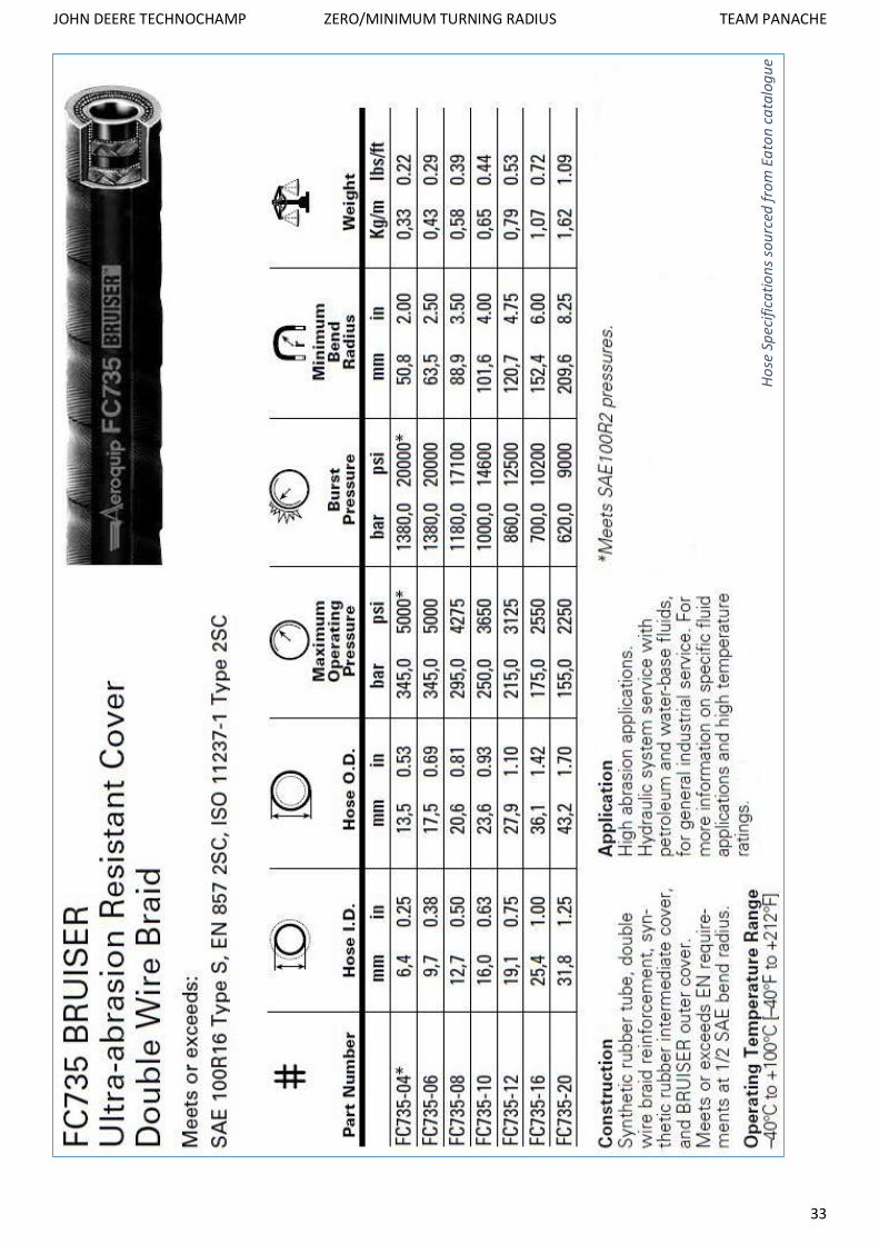
The selected hose model number is FC 735-06 BRUISER.
It supports a maximum continuous operating pressure of up to 5000 PSI and has two layers of braided wire reinforcement around its synthetic rubber fluid tube, along with a “BRUISER” outer cover for added durability.
Other than farming, this hose can even be used in forestry and other off- highway applications. The “BRUISER” cover offers protection against abrasion, chemical and environmental effects, hence making this hose favourable for our application.
Fluids that can be used are petroleum & water based.
Operating Temperature Ranges from -400C to 1000C making this hose suitable to use in various climates as well as altitudes.
JOHN DEERE TECHNOCHAMP ZERO/MINIMUM TURNING RADIUS TEAM PANACHE
33
Ho
se S
pec
ific
ati
on
s so
urc
ed f
rom
Ea
ton
ca
talo
gu
e

JOHN DEERE TECHNOCHAMP ZERO/MINIMUM TURNING RADIUS TEAM PANACHE
34
SIM
ULI
NK
CIR
CU
IT F
OR
SIM
ULA
TIN
G T
HE
HST
’s P
ERFO
RM
AN
CE
SIM
ULI
NK
Cir
cuit
of
the
Hyd
rost
ati
c Tr
ansm
issi
on S
yste
m (
HST
)

JOHN DEERE TECHNOCHAMP ZERO/MINIMUM TURNING RADIUS TEAM PANACHE
35
Simulink Circuit Component Description:
Engine Input Signal block:
This is a signal of engine output speed (rpm) v/s time (seconds). It simulated the engine output that is fed to the pump.
Simulink-PS Converter block:
Converts the dimensionless Simulink input signal to a Physical Signal.
Rotational Coupling block:
A rotational coupling has been used to couple the engine with the pump. The rotational coupling is basically used to couple mechanical component and hydraulic and hence it has been used in our circuit wherever required.
Ideal Angular Velocity Source:
The block represents an ideal source of angular velocity that generates velocity differential at its terminals proportional to the physical input signal. The source is ideal in a sense that it is assumed to be powerful enough to maintain specified velocity regardless of the torque exerted on the system.
Hydraulic Pump:
We have selected a uni-directional, hydraulic pump in our simulation.
The three ports of the pump are:
S port – it is the suction port of the pump which is connected to the engine output via the rotational coupling.
T port – this port is connected to the reservoir.
P port – this port is connected to the Directional control Valve.
Hydraulic Fluid block:
This block represents the type of fluid used and helps in simulating its properties in the circuit.
Hydraulic fluid used is SAE DTE 24 in our actual solution. Although in Simulink we have used an oil of SAE 30 grade because of the similarity in properties of the two oils & the unavailability of SAE DTE 24 in the software.
Solver Block:
A Solver block has been added to the circuit to provide global information and provide parameters so that simulation can start.
Hydraulic Reference block:
This block simulated the reservoir as we have design our system as an open circuit.
Pressure Relief Valve:
A Pressure Relief Valve is employed in the circuit to relieve any excess pressure in the circuit.
Hydraulic Motor:
Two bi-directional hydraulic motor is used in our design. These hydraulic motor blocks are used to represent the independent left and right motors in Simulink.
Drive shaft Inertia block:
It is connected to the output coming from the motors to simulate the rotational inertia of the drive shaft.
Tire blocks (L & R):
The tire blocks are used to simulate the tire size as it reflects upon the on road velocity.

JOHN DEERE TECHNOCHAMP ZERO/MINIMUM TURNING RADIUS TEAM PANACHE
36
Vehicle Body block:
The vehicle body block includes parameters such as vehicle weight, air drag, etc. It is used to create a realistic simulation of the actual tractor.
Velocity Scope:
This scope is connected to the output of the vehicle body block. It is used to generate the output graph of road velocity v/s time.
Gain:
This block has been connected because the velocity signal is in terms of kmph but we want acceleration in m/s2, so it multiplies the velocity signal by a factor of (1000/3600).
Derivative block:
This block derives the output velocity of the vehicle dynamics block and generated an acceleration v/s time signal.
Acceleration Scope:
This Scope is connected to the output from the derivative block so as to produce an acceleration v/s time plot.
Comparison of SIMULINK Graphs & Excel Graphs:
Although the graphs may be similar in nature there are some noticeable differences. The SIMULINK graphs are based on a real-time simulation which takes into consideration various parameters such as fluid properties, miscellaneous losses, efficiency of almost all components, etc., whereas in Ms Excel we have only considered pump and motor mechanical efficiency.
Thus the graphs generated by SIMULINK are more realistic in nature however it would be very difficult to describe the behaviour as compared to the graphs generated by Excel. The SIMULINK circuit also factors in the hydraulic fluid properties, shaft inertias, as well as pressure relief valve settings which have been neglected in the Excel calculations.
The acceleration curve especially may tend to vary, as in excel we have had to assume the velocity when calculating air drag torque. These assumptions based on hit & trial may give rise to error in the nature of the acceleration curve.
It should also be noted that the acceleration in the excel sheets is calculated based on torque and inertia which are found based on assumptions however in Simulink the acceleration is found by derivation of the velocity output for the same time interval. Thus the Simulink graphs have a higher degree of accuracy.
For the purpose of evaluating the accuracy of the Excel graphs we have calculated the Normalised Root Mean Square Deviation with respect to the SIMULINK graphs, for both (velocity & acceleration).

JOHN DEERE TECHNOCHAMP ZERO/MINIMUM TURNING RADIUS TEAM PANACHE
37
SIM
ULI
NK
v/s
EX
CEL
(V
elo
city
v/s
Tim
e)
JOHN DEERE TECHNOCHAMP ZERO/MINIMUM TURNING RADIUS TEAM PANACHE
38
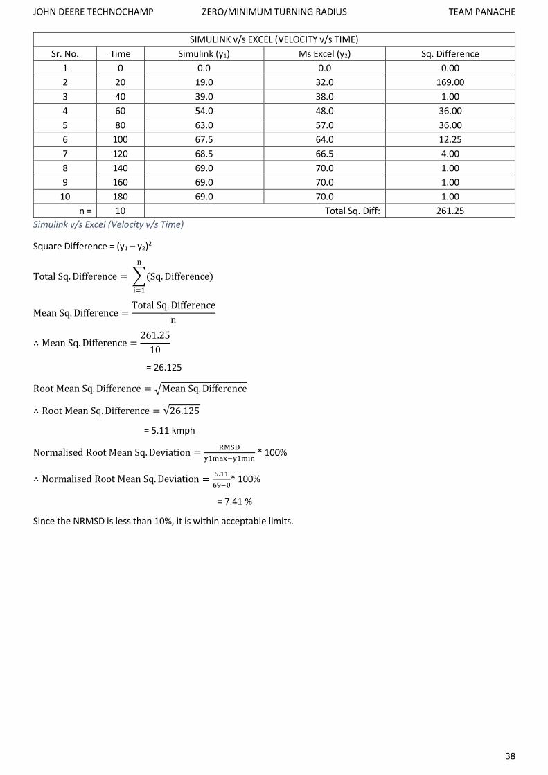
SIMULINK v/s EXCEL (VELOCITY v/s TIME)
Sr. No. Time Simulink (y1) Ms Excel (y2) Sq. Difference
1 0 0.0 0.0 0.00
2 20 19.0 32.0 169.00
3 40 39.0 38.0 1.00
4 60 54.0 48.0 36.00
5 80 63.0 57.0 36.00
6 100 67.5 64.0 12.25
7 120 68.5 66.5 4.00
8 140 69.0 70.0 1.00
9 160 69.0 70.0 1.00
10 180 69.0 70.0 1.00
n = 10 Total Sq. Diff: 261.25
Simulink v/s Excel (Velocity v/s Time)
Square Difference = (y1 – y2)2
Total Sq. Difference = ∑(Sq. Difference)
n
i=1
Mean Sq. Difference =Total Sq. Difference
n
∴ Mean Sq. Difference =261.25
10
= 26.125
Root Mean Sq. Difference = √Mean Sq. Difference
∴ Root Mean Sq. Difference = √26.125
= 5.11 kmph
Normalised Root Mean Sq. Deviation =RMSD
y1max−y1min * 100%
∴ Normalised Root Mean Sq. Deviation =5.11
69−0* 100%
= 7.41 %
Since the NRMSD is less than 10%, it is within acceptable limits.

JOHN DEERE TECHNOCHAMP ZERO/MINIMUM TURNING RADIUS TEAM PANACHE
39
SIM
ULI
NK
v/s
EX
CEL
(A
ccel
era
tio
n v
/s T
ime)
JOHN DEERE TECHNOCHAMP ZERO/MINIMUM TURNING RADIUS TEAM PANACHE
40
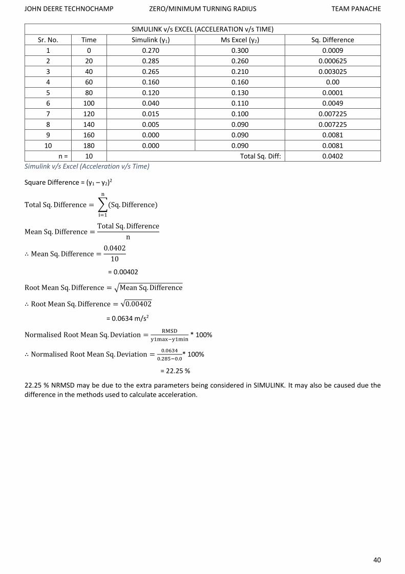
SIMULINK v/s EXCEL (ACCELERATION v/s TIME)
Sr. No. Time Simulink (y1) Ms Excel (y2) Sq. Difference
1 0 0.270 0.300 0.0009
2 20 0.285 0.260 0.000625
3 40 0.265 0.210 0.003025
4 60 0.160 0.160 0.00
5 80 0.120 0.130 0.0001
6 100 0.040 0.110 0.0049
7 120 0.015 0.100 0.007225
8 140 0.005 0.090 0.007225
9 160 0.000 0.090 0.0081
10 180 0.000 0.090 0.0081
n = 10 Total Sq. Diff: 0.0402
Simulink v/s Excel (Acceleration v/s Time)
Square Difference = (y1 – y2)2
Total Sq. Difference = ∑(Sq. Difference)
n
i=1
Mean Sq. Difference =Total Sq. Difference
n
∴ Mean Sq. Difference =0.0402
10
= 0.00402
Root Mean Sq. Difference = √Mean Sq. Difference
∴ Root Mean Sq. Difference = √0.00402
= 0.0634 m/s2
Normalised Root Mean Sq. Deviation =RMSD
y1max−y1min * 100%
∴ Normalised Root Mean Sq. Deviation =0.0634
0.285−0.0* 100%
= 22.25 %
22.25 % NRMSD may be due to the extra parameters being considered in SIMULINK. It may also be caused due the difference in the methods used to calculate acceleration.
JOHN DEERE TECHNOCHAMP ZERO/MINIMUM TURNING RADIUS TEAM PANACHE
41
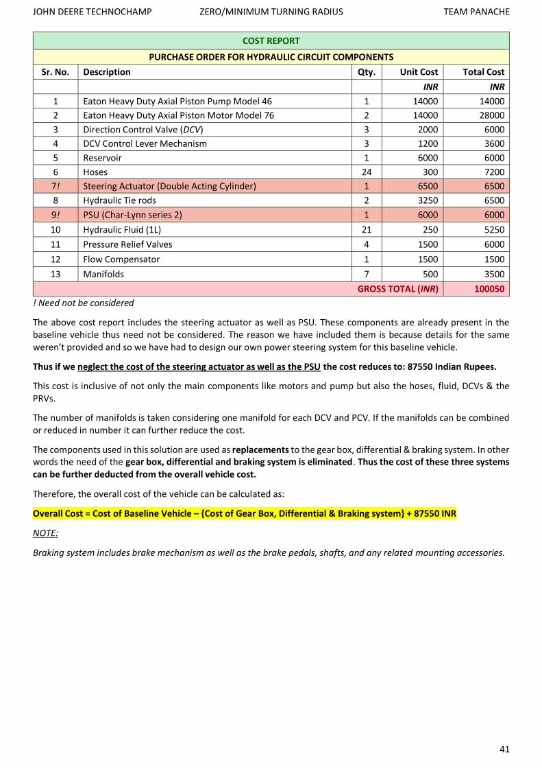
COST REPORT
PURCHASE ORDER FOR HYDRAULIC CIRCUIT COMPONENTS
Sr. No. Description Qty. Unit Cost Total Cost
INR INR
1 Eaton Heavy Duty Axial Piston Pump Model 46 1 14000 14000
2 Eaton Heavy Duty Axial Piston Motor Model 76 2 14000 28000
3 Direction Control Valve (DCV) 3 2000 6000
4 DCV Control Lever Mechanism 3 1200 3600
5 Reservoir 1 6000 6000
6 Hoses 24 300 7200
7! Steering Actuator (Double Acting Cylinder) 1 6500 6500
8 Hydraulic Tie rods 2 3250 6500
9! PSU (Char-Lynn series 2) 1 6000 6000
10 Hydraulic Fluid (1L) 21 250 5250
11 Pressure Relief Valves 4 1500 6000
12 Flow Compensator 1 1500 1500
13 Manifolds 7 500 3500
GROSS TOTAL (INR) 100050
! Need not be considered
The above cost report includes the steering actuator as well as PSU. These components are already present in the baseline vehicle thus need not be considered. The reason we have included them is because details for the same weren’t provided and so we have had to design our own power steering system for this baseline vehicle.
Thus if we neglect the cost of the steering actuator as well as the PSU the cost reduces to: 87550 Indian Rupees.
This cost is inclusive of not only the main components like motors and pump but also the hoses, fluid, DCVs & the PRVs.
The number of manifolds is taken considering one manifold for each DCV and PCV. If the manifolds can be combined or reduced in number it can further reduce the cost.
The components used in this solution are used as replacements to the gear box, differential & braking system. In other words the need of the gear box, differential and braking system is eliminated. Thus the cost of these three systems can be further deducted from the overall vehicle cost.
Therefore, the overall cost of the vehicle can be calculated as:
Overall Cost = Cost of Baseline Vehicle – {Cost of Gear Box, Differential & Braking system} + 87550 INR
NOTE:
Braking system includes brake mechanism as well as the brake pedals, shafts, and any related mounting accessories.

JOHN DEERE TECHNOCHAMP ZERO/MINIMUM TURNING RADIUS TEAM PANACHE
42
Ergonomics:
Since we are not using a gear box, the vehicle will not require a gear shifter or a clutch pedal. The vehicle will operate
similar to a CVT driven vehicle, with simply one accelerator pedal. Since the conventional braking system is eliminated,
the vehicle will not require the brake pedals. The braking will be achieved with the lock positions on the corresponding
motor’s DCV.
The dash panel will look something similar to what is seen above. There will be a steering wheel which is connected
to the PSU. There will be a display which may include tachometer, speedometer, engine temperature, etc. Since in
India we normally drive with the gear shifter in our left hand, we have put the 3 DCV controls on the left hand side of
the steering wheel, within easily accessible distance (or rather within the reach envelope of the driver).
The DCV’s controls are broadly labelled as L, Z & R.
L = controls rear left wheel’s motor
R = controls rear right wheels motor
Z = this DCV is used to actuate the zero turn tie rods.
The double acting steering actuator is connected to the PSU which is controlled by the steering wheel.
The central DCV which controls the hydraulic tie rods, has its three positions labelled as E, L & R which stand for Expand,
Lock & Retract. The L & R DCVs have their three positions labelled as F, L & R which stands for Forward, Lock & Reverse.
There is a blue line shown in the figure which connects the central DCV to the lock position of the L & R DCVs. This is
a means of fool proofing. It reminds the driver that before the central lever is used, the L & R DCVs must be in lock
position. In other words the vehicle must be stationary before going into or coming out of zero turning mode. Once
the wheels have turned, the central DCV should be locked and the L & R DCV should be put into opposite positions
(one in forward & the other in reverse). Depending on which is in forward and which is in reverse the vehicle will either
turn clockwise or counter-clockwise when seen from above. As a fail-safe, if the zero turn tie rods are being actuated
& at the same time the wheels are rotating the power requirement will exceed what the prime mover is capable of
supplying & thus the system will stall before tremendous forces are experienced by the tie rods and other steering
system members.
Ergonomics

JOHN DEERE TECHNOCHAMP ZERO/MINIMUM TURNING RADIUS TEAM PANACHE
43
Value Proposition:
Zero turning & regular turning operations:
If you consider zero turning as moving about a pivot point, this is achieved in our solution. The baseline vehicle has a minimum turning radius of exactly 3099 mm (brake assisted). This means when the front wheels are fully turned to one side (full right for example) and corresponding right brake on the right rear tire is applied. The vehicle will take the tightest possible right turn with a turning radius of 3099 mm. This method of turning has not been eliminated in our solution. The tractor is still capable of turning in this fashion as seen in the diagrams on pages 6 & 7. In addition to this, the tractor has also been given the capability to take a zero turn about the vertical pivot axis located in the middle of the two rear wheels. The rotation of the vehicle is achieved by the rear wheels rotating in opposite directions simultaneously. The speed of rotation can be controlled by the driver. The means by which the rear wheels rotate in opposite directions is achieved in our solutions by means of hydrostatic transmission system. The baseline vehicle has a gear box and differential, which cannot enable the rear wheels to rotate in opposite directions simultaneously. The radius of turn envelope of a zero turn as seen on page 8, is 2156 mm. This is almost 1 meter less than what the baseline vehicle is capable of. In fact the wall to wall distance between which the vehicle can take a zero turn is actually 3377mm!! As proven below:
Wall to Wall Distance

JOHN DEERE TECHNOCHAMP ZERO/MINIMUM TURNING RADIUS TEAM PANACHE
44
Transmission:
When it comes to the transmission system, the first thing to be noticed is that we have taken a baseline vehicle which on paper has a rated top speed of 31.2 kmph (forward) & 24 kmph (reverse), & by means of hydrostatic transmission we have effectively been able to make the vehicle run at 70 kmph. Since the transmission is of hydrostatic type, it gives symmetrical performance in forward as well as reverse. Thus the top speed in forward as well as in reverse is close to 70 kmph. We have done this because in India we often find tractors having to cut across cities and thus creating traffic problems due to their width (making it difficult to overtake on narrow roads or single lane road) and slow speed. Thus the means of moving at 70kmph rather than 31.2 kmph should solve this problem to a certain extent.
In case the company wants to limit the speed to around 31.2 kmph then it would be possible to use a smaller pump and motor and thus even a smaller engine (lesser horse power) would suffice. Thus it would bring down the overall cost, making it more affordable for the Indian economy. It would also reduce the overall weight of the tractor.
Finance:
In this solution we have eliminated the gear box, differential and braking system and replaced these with the hydrostatic transmission system for the reason mentioned above. Thus the cost difference would not be too much. The cost of all the parts used in the hydraulic circuit is nearly 1 lakh. However, since the baseline vehicle already comes with its own power steering circuit, this cost can be neglected making the overall change cost around 87550 Indian rupees. We must also note that since the vehicle will not require a gear box, differential and braking system as these are all included in the HST system, the cost of these systems can be further deducted from the overall cost. Thus the net cost of the vehicle with zero turning capabilities will not differ much from the cost of the existing baseline vehicle. If the cost of the gear box, differential & braking system is more than 87550 Indian rupees, the net cost will be even less than that of the baseline vehicle.
Troubleshooting & Debugging:
From an engineer’s point of view we have now combined the steering, braking and transmission system in the same hydraulic circuit. Any glitch in the same would not go unnoticed as:
1. A fault in any part of the circuit such as a leak would be easily noticed. 2. If there is a leak in any of the hoses, since none of the circuits are independent of one another the entire
system will fail to operate making the fault easily detectable.
For example, if there is a problem in the brakes of the baseline vehicle, it will go unnoticed until the driver wishes to apply the brakes. In our solution, if there is a fault in the circuit such as a leak, not only will it affect the braking performance, but the pressure will not build up and thus the transmission will also not work effectively, making it obvious to the driver that something is wrong. It is an example of an inherent fail-safe in the hydraulic circuit.
Detecting the source of error, would also be very simple as technically there are only three parts in our hydraulic circuit:
1. Steering line 2. Zero turning line 3. HST lines (L & R)
The serviceman or user would simply have to check these three lines and thus detecting the leak would not be a very tedious task. The chances of leaks are quite less as the hose we have selected can be used for continuous operation at pressures ranging up to 5000 PSI, whereas we have limited the pressure to 4500 PSI in our solution. Nevertheless, in case of leak or burst, the cost of a hose with its end fittings is not very expensive (as seen in the cost report) and considering mass production, the cost of such a spare part can be easily brought down.
Serviceability:
Ideally, a designer would want to design any automobile such that the time it spends under servicing is as less as possible. This would:
1. Enable service team to repair/take care of more problems in less time. 2. Keep customers satisfied. 3. Prevent a buildup of vehicles thus reduce storage space required.
JOHN DEERE TECHNOCHAMP ZERO/MINIMUM TURNING RADIUS TEAM PANACHE
45
Simply put, the vehicle should be serviced as quickly as possible & the frequency of failure of components should be as less as possible.
From the cost report parts such as the motors and pump, which are costliest, are also the most reliable and may also come with a warranty period.
Other parts which have a higher tendency to fail such as hoses are much less expensive in comparison and hardly any dismantling is required to replace a hose. These can be replaced within minutes once the faulty hose is detected.
Only the actuators and manifolds (containing the DCVs & PRVs) have to be mounted. The hoses are simply fastened into the correct holes with a wrench.
Maintenance:
Normally in a gear box driven system one must check the oil level, occasionally drain and replace the oil etc. Same will have to be done for the engine. In our design the inspection can easily be done by opening the reservoir tank (when the vehicle is not switched on). The filters can also be checked and replaced occasionally, if required.
Ergonomics:
In our solution we have eliminated the clutch pedal, brake pedal and gear shifter. Instead there are only 3 DCV control levers. This makes operating the tractor very simple. The tractor would operate similar to an automatic vehicle or a CVT driven vehicle. The DCV controls can either be on the left or right of the steering wheel depending on user preference. For example, in India we normally have the gear shifter on our left hand side, so in countries like India a left hand side DCV control would be easier to get used to.
What about other Tractor Models?
The value proposition mentioned above pertains specifically to the 5065 E model, however the same methodology provided in our solution can be applied to any tractor or four wheeled vehicle.
Speed to the Market?
The technology that we have used in our solution is not new by any means. It already exists and is commercially available, thus making the solution technically feasible. We have only designed a circuit using these parts so as to endow the tractor with zero turning capabilities. The actuator’s mounting locations and mounting plates will have to be decided & this should not consume a lot of time. This is a simple process and even preparing a prototype should not be very time consuming. Once a successful prototype is built the design can be mass produced. If we consider one week to finalize the mounting plate locations and make necessary changes (like drill holes for bolting locations), followed by 3 weeks of testing the prototype and fixing any bugs, then we could have a final design ready within one months’ time.
Incremental Innovation or Breakthrough Innovation?
This innovation if proven successful would definitely be a breakthrough. We highly doubt it would fail as similar concepts are commercially seen, such as the John Deere Skid Steer. The fact that the zero turning vehicle will be able to turn within a wall to wall distance of only 3377 mm is quite remarkable considering that the baseline vehicle has a brake assisted turning radius of 3099 mm.

JOHN DEERE TECHNOCHAMP ZERO/MINIMUM TURNING RADIUS TEAM PANACHE
46
Renders of Vehicle:
Bottom View
Top View

JOHN DEERE TECHNOCHAMP ZERO/MINIMUM TURNING RADIUS TEAM PANACHE
47
A T
ract
or
in Z
ero
Tu
rnin
g M
ode