zwischenflansch- rückschlagarmaturen wafer type · pdf filecarbon steel stainless steel...
TRANSCRIPT

Valve Experience. Made in Germany.
Für alle AnwendungenFor any application
Zwischenflansch- RückschlagarmaturenWafer Type Check Valves
3
InhaltsverzeichnisContents
Rückschlagarmaturen Check Valves
Zwischenflansch-Doppelrückschlagklappen API Wafer Type Dual Plate Check Valve API 4
Zwischenflansch-Doppelrückschlagklappen DIN Wafer Type Dual Plate Check Valve DIN 6
Anschlussvarianten Connection Versions 8
Baulängen F / F Dimensions 9
Armaturenprüfstand Check Valve Test Facility 10
Zwischenflansch-Rückschlagventile Wafer Type Lift Check Valve 12
Zwischenflansch-Rückschlagklappen Wafer Type Swing Check Valve 16
Einbau Installation 18
Auslegung Dimensioning 19
Druckverlustdiagramme Pressure Drop Diagrams 20
Dichtungen Seat Rings 24
Werkstoffe Materials 25
Beispielhafte Prüfungen und Zertifikate Exemplary Testings and Certificates 26
Abnahmen Inspections 28
Unser weiteres Programm Entire Product Range 30
Weltweite Verfügbarkeit Present Worldwide 31
Technische Änderungen vorbehalten 07 / 2014Technical modifications reserved 07 / 2014
Made in GermanyJahrzehntelange Erfahrungen und weltweite Referenzen für den Einsatz unserer Armaturen unter den extremen Einsatzbedingungen von Chemie, Pharma, Raffinerien und Anlagenbau bestätigen immer wieder die Leistungsfähigkeit unseres Unternehmens. Als ein weltweit führender Spezialist für die Planung, Konstruktion und Fertigung von Rückschlagarmaturen, Bodenventilen und Probe- nahmeventilen verbindet RITAG Produkte und Service zu maximalem Kundennutzen.
Prozesssicherheit durch erstklassiges Engineering. Flexibel und schnell in der Umsetzung Ihrer Wünsche und Anforderungen. Und nicht zuletzt: Höchste Verfügbarkeit Ihrer Anlagen und Systeme durch ein weltumspannendes Netz von Servicepartnern. RITAG Serienarmaturen sowie Sonder- ausführungen sind in allen prozesserforderlichen Nennweiten, Druckstufen und Werkstoffen liefer- bar. Unsere Ingenieure sorgen für eine Verwendbarkeit der RITAG Produkte nach allen internatio- nalen Normen und Vorschriften.
Made in GermanyDecades of experience and worldwide project references for the use of our non-return valves under the extreme operating conditions of the chemical and pharmaceutical industries, refineries and plant construction confirm our company’s high performance time and time again. As a world- leading specialist in the planning, design and manufacturing of check valves, bottom valves and sampling valves, RITAG focuses its products and service on achieving maximum customer benefit.
Process reliability through first-class engineering. Flexible and fast in realising your specifications and requirements. And last but not least: Maximum availability of your plant and systems by means of a global network of service partners. RITAG standard non-return valves and special designs are available in all nominal dimensions, pressure ratings and materials required for specific pro- cesses. Our engineers ensure that RITAG products operate in accordance with all international standards and regulations.
QualitätQuality

4 5
Zwischenflansch-DoppelrückschlagklappenWafer Type Dual Plate Check Valve
Type ZRD / API
Auslegungs- und Berechnungshinweise finden Sie auf den Seiten 18 – 25.
For further information on dimensioning and calculating of valves, please see pages 18 – 25.
Technische Datenblätter zu den Einzeltypen finden Sie unter www.ritag.com.
Technical data sheets are available on our web site www.ritag.com.
*) Größere Nennweiten auf Anfrage. Larger sizes on request.
Type ZRD DCI ZRD CS ZRD LTCS ZRD SS ZRD DSS ZRD SDSS ZRD AB ZRD TI ZRD HA
MaterialgruppeMaterial Group
Ductile Cast Iron Carbon Steel Low TemperatureCarbon Steel
Stainless Steel Duplex Stainless Steel
Super DuplexStainless Steel
Aluminium Bronze Titanium High Alloy
Ausführung / Design Stopfbuchslos / Retainerless Stopfbuchslos / Retainerless
DN / Size Nennweite 2" – 56" *) 2" – 56" *) 2" – 56" *) 2" – 56" *) 2" – 56" *) 2" – 56" *) 2" – 56" *) 2" – 24" *) 2“ – 24“ *)Nom. Diameter
PN Nenndruck Min / Min Class 125 Class 150 Class 150 Class 150 Class 150 Class 150 Class 150 Class 150 Class 150Pressure Rating Max / Max Class 250 Class 2500 Class 2500 Class 2500 Class 2500 Class 2500 Class 300 Class 300 Class 2500
Typische Werkstoffe / Typical Materials
Gehäuse / Body Stab / Bar A105 A350 LF2 A 182 F316 L A 182 F51 A 182 F53 B348 Gr. 2 Nickel - Basis - Legierungen /
Nickle - Based - Alloys
Guss / Casting A536 – 60 – 40 – 18 A216 Gr. WCB A352 Gr. LCB A351 Gr. CF8M UNS J92205,A995 Gr. 4A
UNS J93380,A995 Gr. 6A
B148 C95800 B367 Gr. 2
Klappe / Plate Stab / Bar A 182 Gr. F6 A 182 F316 L A 182 F316 L A 182 F51 A 182 F53 B348 Gr. 2 Nickel - Basis - Legierungen /
Nickle - Based - Alloys
Guss / Casting A536 – 60 – 40 – 18 A217 CA15 A351 Gr. CF8M A351 Gr. CF8M UNS J92205,A995 Gr. 4A
UNS J93380,A995 Gr. 6A
B148 C95800
Feder / Spring SS Inconel X750 Inconel X750 Inconel X750 Inconel X750 Inconel X750 Inconel X750 Titanium Gr. 5 Nickel - Basis - Legierungen /
Nickle - Based - Alloys
Innenteile / Internals SS 316 Ti SS 316 Ti SS 316 Ti SS 316 Ti A 182 F53 A 182 F53 B148 C95800 B348 Gr. 2 Nickel - Basis - Legierungen /
Nickle - Based - Alloys
Sitz / Seat Metallisch / Metal to Metal Metallisch / Metal to Metal
Weichdichtend / Soft Seating EPDM, NBR, FKM, FFKM
Weichdichtend / Soft Seating EPDM, NBR, FKM, FFKM
Dichtfläche / Trim – Entsprechend API 594 / According to API 594 Entsprechend API 594 / According to API 594
Baulänge / F / F Dimension Entsprechend API 594, siehe Seite 9 / According to API 594, see page 9 Entsprechend API 594, siehe Seite 9 / According to API 594, see page 9
Durchflussrichtung / Direction of Flow ↔↑ ↔↑ ↔↑ ↔↑ ↔↑ ↔↑ ↔↑ ↔↑ ↔↑

6 7
Zwischenflansch-DoppelrückschlagklappenWafer Type Dual Plate Check Valve
Type ZRD / DIN
Auslegungs- und Berechnungshinweise finden Sie auf den Seiten 18 – 25.
For further information on dimensioning and calculating of valves, please see pages 18 – 25.
Technische Datenblätter zu den Einzeltypen finden Sie unter www.ritag.com.
Technical data sheets are available on our web site www.ritag.com.
*) Größere Nennweiten auf Anfrage. Larger sizes on request.
Type ZRD 1 ZRD 2 ZRD 3 ZRD 4 ZRD G ZRD G – 4 ZRD G – 4 – g ZRD TI ZRD HA
MaterialgruppeMaterial Group
StahlCarbon Steel
EdelstahlStainless Steel
EdelstahlStainless Steel
BronzeBronze
GraugussCast Iron
GraugussCast Iron
GummiertRubber Lined
Titanium High Alloy
Ausführung / Design Stopfbuchslos auf Anfrage / Retainerless on request Stopfbuchslos auf Anfrage / Retainerless on request
DN / Size Nennweite 50 – 1400 *) 50 – 1400 *) 50 – 1400 *) 50 – 1400 *) 50 – 1400 *) 50 – 1400 *) 50 – 1400 *) 50 – 600 *) 50 – 600 *)Nom. Diameter
PN Nenndruck Gruppe 1 / Group 1 6 / 10 / 16 / 25 / 40 6 / 10 / 16 / 25 / 40 6 / 10 / 16 / 25 / 40 6 / 10 / 16 6 / 10 / 16 6 / 10 / 16 6 / 10 / 16 6 / 10 / 16 6 / 10 / 16Pressure Rating Gruppe 2 / Group 2 63 – 160 63 – 160 63 – 160
Typische Werkstoffe / Typical Materials
Gehäuse / Body Stab / Bar 1.0460 1.4301 1.4404 3.7035 Nickel - Basis -Legierungen /
Nickle - Based - Alloys
Guss / Casting 1.0619 1.4308 1.4408 CC483K EN – JL 1040 EN – JL 1040 EN – JL 1040 /Gummiert /
Rubber Lined
3.7264
Klappe / Plate Stab / Bar 1.0425 / 1.0460 1.4301 1.4404 3.7035 Nickel - Basis -Legierungen /
Nickle - Based - Alloys
Guss / Casting 1.4408 / 1.0619 1.4308 1.4408 CC483K EN – JS 1030 CC483K CC483K
Feder / Spring 1.4571 1.4571 1.4571 1.4571 1.4571 1.4571 1.4571 3.7165 Nickel - Basis -Legierungen /
Nickle - Based - Alloys
Innenteile / Internals 1.4571 1.4571 1.4571 1.4571 1.4571 1.4571 1.4571 3.7035 Nickel - Basis -Legierungen /
Nickle - Based - Alloys
Sitz / Seat Metallisch / Metal to Metal Metallisch / Metal to Metal
Weichdichtend / Soft Seating EPDM, NBR, FKM, FFKM
Weichdichtend / Soft Seating EPDM, NBR, FKM, FFKM
Dichtfläche / Trim Optional 1.4370 / Optional 1.4370 –
Baulänge / F / F Dimension Gruppe 1 / Group 1
Gruppe 2 / Group 2
Entsprechend EN 558 Reihe 16, siehe Seite 9According to EN 558 Line 16, see page 9
Entsprechend API 594, siehe Seite 9According to API 594, see page 9
Entsprechend EN 558 Reihe 16, siehe Seite 9According to EN 558 Line 16, see page 9
Entsprechend API 594, siehe Seite 9According to API 594, see page 9
Durchflussrichtung / Direction of Flow ↔↑ ↔↑ ↔↑ ↔↑ ↔↑ ↔↑ ↔↑ ↔↑ ↔↑

8 9
AnschlussvariantenConnection Versions
Wafer TypeDie Rückschlagklappe wird durch die Schrauben zwischen zwei Flanschen fixiert. Die Anzahl der erforderlichen Schrauben entspricht der Anzahl der Schraubenbohrungen im Flansch. Die erforderliche Länge der Schrauben kann wie folgt abgeschätzt werden: Gehäuselänge + 2,2 x (Flanschdicke + Dichtung + Mutter)
RITAG liefert die Doppelrückschlagklappen passend zu allen gängigen Flanschnormen und den entsprechen-den Dichtleistenformen. Beispiele für Flanschnormen sind:
EN 1092 ASME B16.5 (bis 24") ASME B16.47 Serien A und B (≥26") JIS B2210 DIN 2501 (ersetzt durch EN 1092)
Für jede Flanschnorm können 4 verschiedene Bauformen gewählt werden:
The check valve is fixed between two flanges using bolts. The number of bolts required corresponds to the number of bolt holes in the flange. The required bolt length can be estimated as follows: housing length + 2.2 x (flange thickness + seal + nut)
RITAG supplies dual plate check valves in accordance to all common flange standards and with the corresponding flange facings. The following are examples of flange standards:
EN 1092 ASME B16.5 (up to 24") ASME B16.47 Series A and B (≥26") JIS B2210 DIN 2501 (replaced by EN 1092)
4 different designs can be chosen for each flange standard:
Solid Lug (through-bolted)Die Rückschlagklappe wird durch die Schrauben zwischen zwei Flanschen fixiert. Die Anzahl der er- forderlichen Schrauben entspricht der Anzahl der Schraubenbohrungen im Flansch. Das Rückschlag-klappengehäuse schütz die Schrauben vor äußeren Einflüssen. Die erforderliche Länge der Schrauben kann wie folgt abgeschätzt werden: Gehäuselänge + 2,2 x (Flanschdicke + Dichtung + Mutter)
The check valve is fixed between two flanges using bolts. The number of bolts required corresponds to the number of bolt holes in the flange. The check valve housing protects the bolts from external influences. The required bolt length can be estimated as follows: body length + 2.2 x (flange thickness + seal + nut)
Tapped Lug (threaded holes)Die Rückschlagklappe ist beidseitig mit Gewindeboh-rungen versehen. Die Anzahl der erforderlichen Schrau- ben entspricht der doppelten Anzahl der Schrauben-bohrungen im Flansch. Durch die kurzen Schrauben ist der Temperatureinfluss auf die Schrauben gering. Die erforderliche Länge der Schrauben kann wie folgt abgeschätzt werden: Länge der Gewindebohrung + 1,1 x (Flanschdicke + Dichtung + Mutter)
The check valve is provided with threaded holes on both sides. The number of bolts required corresponds to double the number of bolt holes in the flange. The shortness of the bolts means the temperature effect on them is low. The required bolt length can be estimated as follows: length of the threaded hole + 1.1 x (flange thickness + seal + nut)
FlangedDie Rückschlagklappe ist beidseitig mit Anschluss-flanschen ausgestattet. Die Anzahl der erforderlichen Schrauben entspricht der doppelten Anzahl der Schraubenbohrungen im Flansch. Durch die kurzen Schrauben ist der Temperatureinfluss auf die Schrau-ben gering. Die erforderliche Länge der Schrauben errechnet sich wie folgt: 2,2 x (Flanschdicke + Dichtung + Mutter)
The check valve is fitted with connection flanges on both sides. The number of bolts required corresponds to double the number of bolt holes in the flange. The shortness of the bolts means the temperature effect on them is low. The required bolt length can be estimated as follows: 2.2 x (flange thickness + seal + nut)
Doppelrückschlagklappen Baulänge „L“Dual Plate Check Valve Length “L“
Die standardisierten Baulängen der Doppelrückschlagklappen ermög- lichen den einfachen Austausch der Armaturen in der Anlage. RITAG liefert die Ausführung PN10 – PN40 mit einer Baulänge nach EN 558 Reihe 16. Alle anderen Druckstufen werden mit Baulängen entsprechend der ASME B16.10 / API 594 ausgeführt.
The standardized length of dual plate check valves guarantees an easy replacement of valves in the plant. RITAG supplies the design PN10 – PN40 with an length according to EN 558 line 16.All ohter designs will be supplied with a length according to ASME B16.10 / API 594.
Aufgrund der o. g. Normbaulängen ist eine Doppelflanschausführung nur bei den grau hinterlegten Ausführungen möglich. Due to the length given by the standards the double flanged design is available for the grey marked sizes only.
Type ZRD / DIN ZRD / API
PN 10 – 40 Class 150 Class 300 Class 600 ( PN 63 – PN 100 )
Class 900 ( PN 160 )
Class 1500 Class 2500
Std EN 558 API 594 API 594 API 594 API 594 API 594 API 594
DN Size Reihe 16 Line 16
50 2 43 60 60 60 70 70 70
65 2,5 46 67 67 67 83 83 83
80 3 64 73 73 73 83 83 86
100 4 64 73 73 79 102 102 105
125 5 70
150 6 76 98 98 136 159 159 159
200 8 89 127 127 165 206 206 206
250 10 114 146 146 213 241 248 254
300 12 114 181 181 229 292 305 305
350 14 127 184 222 273 356 356
400 16 140 191 232 305 384 384
450 18 152 203 264 362 451 468
500 20 152 219 292 368 451 533
600 24 178 222 318 438 495 559

10 11
ArmaturenprüfstandCheck Valve Test Facility
Der Trend im weltweiten Anlagenbau, speziell in der Öl- und Gasindustrie, geht zu immer höheren Drücken und zu immer größeren Nennweiten. Es genügt dabei nicht, die Armaturen zu fertigen, man muss diese auch prüfen können.
Deshalb betreibt RITAG einen der größten Armaturen- prüfstände seiner Art in Deutschland. Die technischen Daten sind mehr als beeindruckend: Bei einem Eigen- gewicht von 45 Tonnen kann der Prüfstand Armaturen mit einer Kraft von 9000 kN einspannen. Das entspricht einem Gewicht von 900 Tonnen!
Mit diesem neuen Prüfstand kann RITAG Armaturen bis zu folgenden Grenzwerten prüfen: Maximale Nennweite: DN 1400 / 56" Maximale Baulänge: 2 m / 80" Maximale Druckstufe: PN 400 / Class 2500
Der Prüfstand steht bei Bedarf auch Fremdfirmen, Gutachtern und Sachverständigen zur Verfügung.
All over the world the trend in plant engineering is towards ever higher pressures and ever larger nominal diameters, especially in the oil and gas industry. This means that it is not enough just to manufacture valves, one must also have the capability to test the valves.
This is why RITAG runs one of the largest test facilities for valves of its kind in Germany. The technical data are more than impressive: With a net weight of 45 tons, the test facility can clamp valves with a force of 9,000 kN. This corresponds to a weight of 900 tons!
This new test facility means that RITAG can test valves up to the following design limits: Maximum nominal diameter: DN 1400 / 56" Maximum face to face dimension: 2 m / 80" Maximum pressure rating PN 400 / Class 2500
On request the test facility is also made available to outside companies, assessors and surveyors.
Die Armaturen können folgenden Prüfungen unterzogen werden: Prüfung der Gehäusefestigkeit mit Wasser Prüfung der Gehäusedichtigkeit mit Luft und Wasser Prüfung der Sitzdichtheit mit Luft und Wasser Prüfung der Festigkeit des Abschlusskörpers mit Wasser
Bei den Prüfungen mit Wasser beträgt der maximale Prüfdruck 650 bar!
Sämtliche Prüfungen können nach allen international anerkannten Normen und Standards erfolgen. Beispiele hierfür sind die EN 12266 und die API 598.
Die Prüfung und die Protokollierung erfolgt in der Regel über rechnergesteuerte Prüfprogramme, jedoch ist eine manuelle Bedienung bei Spezialfällen ebenso möglich. Generell werden alle Messgrößen elektronisch erfasst und ausgewertet.
Valves can undergo the following tests: Testing of shell strength with water Testing of shell tightness with air and water Testing of seat tightness with air and water Testing of the strength of the discs with water.
For water tests the maximum test pressure is 650 bar!
All testings can be carried out in accordance with all internationally approved standards, like EN 12266 and API 598.
For testing and logging computer-controlled test programs are normally used, but manual operation is also possible in special cases. In general, all measurements are electronically recorded and analysed.
RITAG DN 1400 / 56" Prüfstand RITAG DN 1400 / 56" Test Facility
Ein wichtiger Aspekt bei der Prüfung ist die elektronische Kraftsteuerung. Sie erhöht die Einspannkraft, mit der die Armatur an den Flanschenden dicht gehalten wird, proportional zum Innendruck der Armatur. Ohne diese Art der Kraftsteuerung könnten ggf. Armaturen verformt werden.
One important aspect of testing is the electronic power control, which increases the clamping force used to keep the valve sealed at the flange ends in proportion to the internal pressure of the valve. Without this electronic power control, valves might in some cases be deformed.
RITAG Rückschlagarmatur vom Typ ZRD API 24" vor der Prüfung RITAG check valve, type ZRD API 24", before testing
Steuerung und Prüfung Control and testing

12 13
Zwischenflansch-Rückschlagventile Wafer Type Lift Check Valve
Auslegungs- und Berechnungshinweise finden Sie auf den Seiten 18 – 25.
For further information on dimensioning and calculating of valves, please see pages 18 – 25.
Technische Datenblätter zu den Einzeltypen finden Sie unter www.ritag.com.
Technical data sheets are available on our web site www.ritag.com.
NennweiteNom. Diameter
15½"
20¾"
251"
321 ¼"
401 ½"
502"
652 ½"
803"
1004"
1255"
1506"
2008"
25010"
30012"
35014"
Baulänge nach EN 558 [mm]F/ F Dimension acc. to. EN 558 [mm]
Reihe 49Line 49
16 19 22 28 31,5 40 46 50 60 90 106 140 – – –
Reihe 52Line 52
25 31,5 35,5 40 45 56 63 71 80 110 125 160 200 250 280
DIN PN 6 – 40 DIN PN 63 – 160 Haustechnik / Building Services
Type SR 12.16 SR 20.40–St SR 20.40 SR 22.40 SR 40.40 SR 30.40 SR 50.40 SR 35.40 SR 55.40 SR 25.40 – St HSR 20.160 – St HSR 30.160 SR 70.06 – KSR 70.16 SR 10.16 TCR
DN / Size Nennweite Nom. Diameter
DN 15 – 200 DN 15 – 200 DN 15 – 200 DN 15 – 200 DN 15 – 200 DN 15 – 200 DN 15 – 200 DN 15 – 200 DN 15 – 200 DN 250 – 350 DN 15 – 200 DN 15 – 200 DN 15 – 100 DN 125 – 200 G 1" + G 1 ¼"
PN Nenndruck Pressure Rating
PN 6 – 40 PN 6 – 40 PN 6 – 40 PN 6 – 40 PN 6 – 40 PN 6 – 40 PN 6 – 40 PN 6 – 40 PN 6 – 40 PN 6 – 40 PN 63 – 160 PN 63 – 160 PN 6 – 16 PN 6 – 16 PN 6 – 10
Material Gehäuse Body
CC438K 1.0577 / 1.0421 1.4006 1.0460 1.0460 1.4404 1.4404 1.0460 1.4404 1.0421 1.0460 1.4404 2.0401 Grauguss Cast Iron
EN – JL 1040
2.0401
Material Platte / Kegel Disc
1.4404 1.4301 / 1.4006 1.4404 1.4404 1.4404 1.4404 1.4404 1.4404 1.4404 1.0460 1.4404 1.4404 PPO1.4301
Grauguss Cast Iron
EN – JL 1040
PPO
Material Feder Spring
1.4571 1.4571oder / or2.4632
1.4571oder / or2.4632
1.4571oder / or2.4632
1.4571oder / or2.4632
1.4571oder / or2.4632
1.4571oder / or2.4632
1.4571oder / or2.4632
1.4571oder / or2.4632
1.4571oder / or2.4632
2.4632 2.4632 1.4571 1.4571 1.4301
BaulängeF / F Dimension
EN 558Reihe 49Line 49
EN 558Reihe 49Line 49
EN 558Reihe 49Line 49
EN 558Reihe 49Line 49
EN 558Reihe 49Line 49
EN 558Reihe 49Line 49
EN 558Reihe 49Line 49
EN 558Reihe 52Line 52
EN 558Reihe 52Line 52
EN 558Reihe 52Line 52
EN 558Reihe 52Line 52
EN 558Reihe 52Line 52
EN 558Reihe 49Line 49
EN 558Reihe 49Line 49
Für Flansche nachFor flanges acc. to
EN 1092 – 1Form B
EN 1092 – 1Form B
EN 1092 – 1Form B
EN 1092 – 1Form B
EN 1092 – 1Form B, C, D
EN 1092 – 1Form B
EN 1092 – 1Form B, C, D
EN 1092 – 1Form B, C, D
EN 1092 – 1Form B, C, D
EN 1092 – 1Form B, C, D
EN 1092 – 1Form B, C, D
EN 1092 – 1Form B, C, D
EN 1092 – 1Form B
EN 1092 – 1Form B
PumpenstutzenPump port
SitzdichtungSealing
metallisch,metal / metalNBR, EPDM,FKM, PTFE
metallisch,metal / metalNBR, EPDM,FKM, PTFE
metallisch,metal / metalNBR, EPDM,FKM, PTFE
metallisch, gepanzert
metal / metal, hard faced
NBR, EPDM,FKM, PTFE
metallisch, gepanzert
metal / metal, hard faced
NBR, EPDM,FKM, PTFE
metallisch,metal / metalNBR, EPDM,FKM, PTFE
metallisch,metal / metalNBR, EPDM,FKM, PTFE
metallisch, gepanzert
metal / metal, hard faced
NBR, EPDM,FKM, PTFE
metallisch,metal / metalNBR, EPDM,FKM, PTFE
metallisch,metal / metalNBR, EPDM,FKM, PTFE
metallisch, gepanzert
metal / metal, hard faced
NBR, EPDM,FKM, PTFE
metallisch,metal / metalNBR, EPDM,FKM, PTFE
metallisch,metal / metalNBR, EPDM
NBR, EPDM
Durchfluss-RichtungFlow direction
↔↑↓ ↔↑↓ ↔↑↓ ↔↑↓ ↔↑↓ ↔↑↓ ↔↑↓ ↔↑↓ ↔↑↓ ↔↑↓ ↔↑↓ ↔↑↓ ↔↑↓ ↔↑↓ ↑
Type SR

14 15
Zwischenflansch-Rückschlagventile Wafer Type Lift Check Valve
Auslegungs- und Berechnungshinweise finden Sie auf den Seiten 18 – 25.
For further information on dimensioning and calculating of valves, please see pages 18 – 25.
Technische Datenblätter zu den Einzeltypen finden Sie unter www.ritag.com.
Technical data sheets are available on our web site www.ritag.com.
NennweiteNom. Diameter
15½"
20¾"
251"
321 ¼"
401 ½"
502"
652 ½"
803"
1004"
1255"
1506"
2008"
25010"
30012"
35014"
Baulänge nach EN 558 [mm] F/ F Dimension acc. to. EN 558 [mm]
Reihe 49Line 49
16 19 22 28 31,5 40 46 50 60 90 106 140 – – –
Reihe 52Line 52
25 31,5 35,5 40 45 56 63 71 80 110 125 160 200 250 280
ANSI Class 150 – 300 ANSI Class 600 – 2500 Spezielle Werkstoffe / Special materials Clean Service
Type SR 40.40 SR 50.40 SR 35.40 SR 55.40 HSR 20.160 – St HSR 30.160 SR 60.06 SR 61.06 SR 31.40 SR 33.40 SR 99 SR 93.16 HYPOS 100
DN / Size Nennweite Nom. Diameter
NPS ½" – 8" NPS ½" – 8" NPS ½" – 8" NPS ½" – 8" NPS ½" – 8" NPS ½" – 8" DN 15 – 100 DN 15 – 100 DN 15 – 100 NPS ½" – 8"
DN 15 – 100 NPS ½" – 8"
DN 15 – 100 NPS ½" – 8"
DN 15 – 100 ½" – 4"
DN 15 – 100 ½" – 4"
PN Nenndruck Pressure Rating
Class 150 Class 150 Class 150 + 300 Class 150 + 300 Class 600 –2500
Class 600 –2500
PN 6 PN 6 PN 6 – 40Class 150 + 300
PN 6 – 40Class 150 + 300
PN 6 – 160Class 150 – 2500
PN 16Class 150
PN 16Class 150
Material Gehäuse Body
A105 A 182 F316 L A105 A 182 F316 L A105 A 182 F316 L PTFE PTFE25% Kohle
25% Carbon
3.7035 2.4610 KundenvorgabeCustomer
specification
1.4435 BN2 1.4435 BN2
Material Platte / Kegel Disc
A 182 F316 L A 182 F316 L A 182 F316 L A 182 F316 L A 182 F316 L A 182 F316 L PTFE PTFE25% Kohle
25% Carbon
3.7035 2.4610 KundenvorgabeCustomer
specification
1.4435 BN2 1.4435 BN2
Material Feder Spring
1.4571oder / or2.4632
1.4571oder / or2.4632
1.4571oder / or2.4632
1.4571oder / or2.4632
2.4632 2.4632 2.4610 2.4610 3.7165 2.4610 KundenvorgabeCustomer
specification
1.4401
BaulängeF / F Dimension
EN 558Reihe 49Line 49
EN 558Reihe 49Line 49
EN 558Reihe 52Line 52
EN 558Reihe 52Line 52
EN 558Reihe 52Line 52
EN 558Reihe 52Line 52
EN 558Reihe 52Line 52
EN 558Reihe 52Line 52
EN 558Reihe 52Line 52
EN 558Reihe 52Line 52
EN 558Reihe 52Line 52
Siehe DatenblattSee Data Sheet
Siehe DatenblattSee Data Sheet
Für Flansche nachFor flanges acc. to
ASME B16.5RF
ASME B16.5RF
ASME B16.5RF, RTJ
ASME B16.5RF, RTJ
ASME B16.5RF, RTJ
ASME B16.5RF, RTJ
EN 1092 – 1Form B
EN 1092 – 1Form B
EN 1092 – 1Form B,C DASME B16.5
RF, RTJ
EN 1092 – 1Form B,C DASME B16.5
RF, RTJ
EN 1092 – 1Form B,C DASME B16.5
RF, RTJ
Orbitalschweißenden nach / Orbital weld ends according to
DIN, ISO, ASME-BPE
Orbitalschweißenden nach / Orbital weld ends according to
DIN, ISO, ASME-BPE
SitzdichtungSealing
metallisch, gepanzert
metal / metal, hard faced
NBR, EPDM,FKM, PTFE
metallisch,metal / metalNBR, EPDM,FKM, PTFE
metallisch, gepanzert
metal / metal, hard faced
NBR, EPDM,FKM, PTFE
metallisch,metal / metalNBR, EPDM,FKM, PTFE
metallisch, gepanzert
metal / metal, hard faced
NBR, EPDM,FKM, PTFE
metallisch,metal / metalNBR, EPDM,FKM, PTFE
PTFE / PTFE PTFE / PTFE metallisch,metal / metalNBR, EPDM,FKM, PTFE
metallisch,metal / metalNBR, EPDM,FKM, PTFE
metallisch,metal / metalNBR, EPDM,FKM, PTFE
EPDM, PTFE,PTFE Compound
EPDM
Durchfluss-RichtungFlow direction
↔↑↓ ↔↑↓ ↔↑↓ ↔↑↓ ↔↑↓ ↔↑↓ ↔↑↓ ↔↑↓ ↔↑↓ ↔↑↓ ↔↑↓ ↔↑↓ ↔↑↓
Type SR
16 17
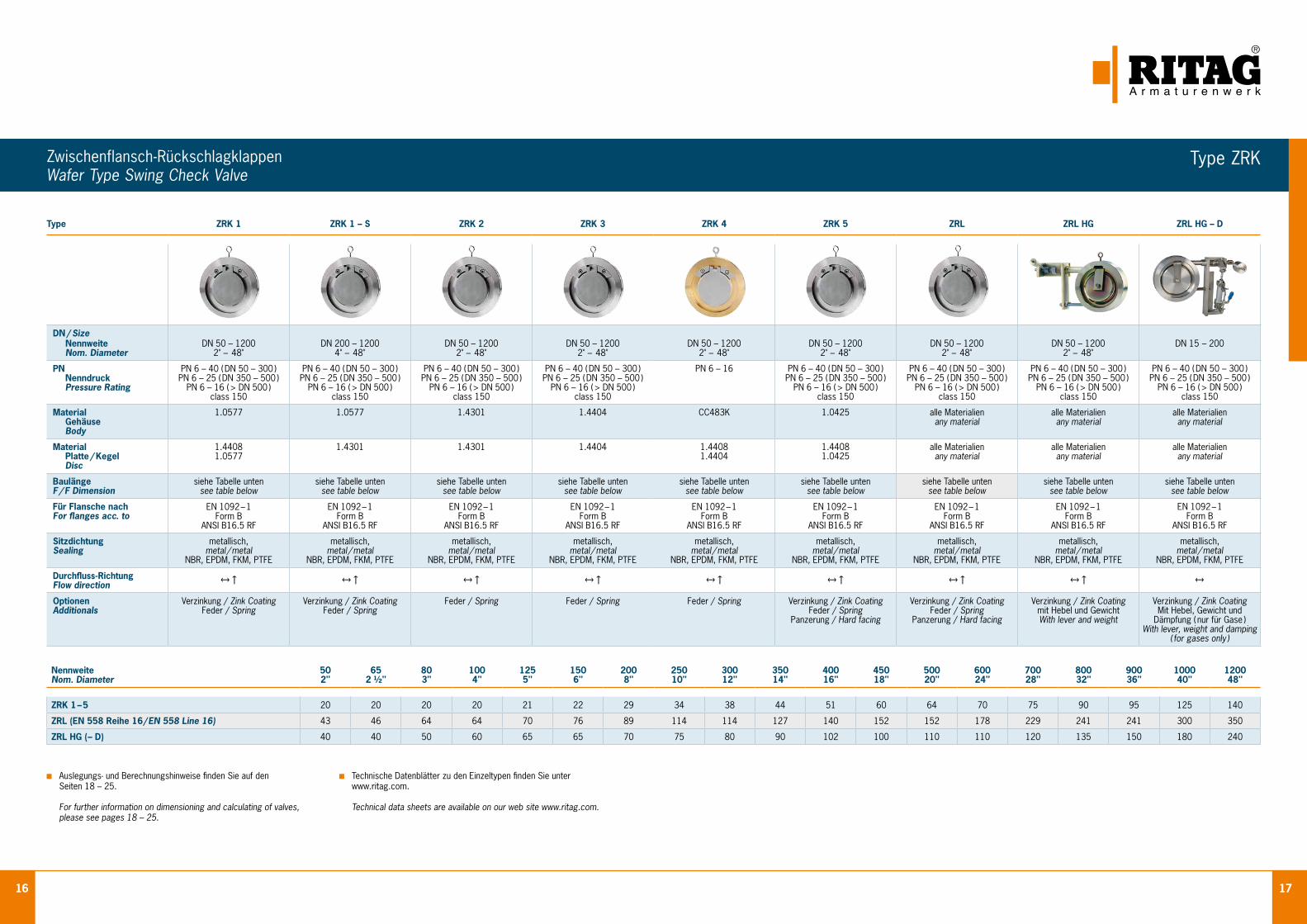
Zwischenflansch-Rückschlagklappen Wafer Type Swing Check Valve
Type ZRK 1 ZRK 1 – S ZRK 2 ZRK 3 ZRK 4 ZRK 5 ZRL ZRL HG ZRL HG – D
DN / Size Nennweite Nom. Diameter
DN 50 – 1200 2" – 48"
DN 200 – 1200 4" – 48"
DN 50 – 1200 2" – 48"
DN 50 – 1200 2" – 48"
DN 50 – 1200 2" – 48"
DN 50 – 1200 2" – 48"
DN 50 – 1200 2" – 48"
DN 50 – 1200 2" – 48"
DN 15 – 200
PN Nenndruck Pressure Rating
PN 6 – 40 ( DN 50 – 300 ) PN 6 – 25 ( DN 350 – 500 )
PN 6 – 16 ( > DN 500 ) class 150
PN 6 – 40 ( DN 50 – 300 ) PN 6 – 25 ( DN 350 – 500 )
PN 6 – 16 ( > DN 500 ) class 150
PN 6 – 40 ( DN 50 – 300 ) PN 6 – 25 ( DN 350 – 500 )
PN 6 – 16 ( > DN 500 ) class 150
PN 6 – 40 ( DN 50 – 300 ) PN 6 – 25 ( DN 350 – 500 )
PN 6 – 16 ( > DN 500 ) class 150
PN 6 – 16 PN 6 – 40 ( DN 50 – 300 ) PN 6 – 25 ( DN 350 – 500 )
PN 6 – 16 ( > DN 500 ) class 150
PN 6 – 40 ( DN 50 – 300 ) PN 6 – 25 ( DN 350 – 500 )
PN 6 – 16 ( > DN 500 ) class 150
PN 6 – 40 ( DN 50 – 300 ) PN 6 – 25 ( DN 350 – 500 )
PN 6 – 16 ( > DN 500 ) class 150
PN 6 – 40 ( DN 50 – 300 ) PN 6 – 25 ( DN 350 – 500 )
PN 6 – 16 ( > DN 500 ) class 150
Material Gehäuse Body
1.0577 1.0577 1.4301 1.4404 CC483K 1.0425 alle Materialien any material
alle Materialien any material
alle Materialien any material
Material Platte / Kegel Disc
1.44081.0577
1.4301 1.4301 1.4404 1.44081.4404
1.44081.0425
alle Materialien any material
alle Materialien any material
alle Materialien any material
BaulängeF / F Dimension
siehe Tabelle untensee table below
siehe Tabelle untensee table below
siehe Tabelle untensee table below
siehe Tabelle untensee table below
siehe Tabelle untensee table below
siehe Tabelle untensee table below
siehe Tabelle untensee table below
siehe Tabelle untensee table below
siehe Tabelle untensee table below
Für Flansche nachFor flanges acc. to
EN 1092 – 1Form B
ANSI B16.5 RF
EN 1092 – 1Form B
ANSI B16.5 RF
EN 1092 – 1Form B
ANSI B16.5 RF
EN 1092 – 1Form B
ANSI B16.5 RF
EN 1092 – 1Form B
ANSI B16.5 RF
EN 1092 – 1Form B
ANSI B16.5 RF
EN 1092 – 1Form B
ANSI B16.5 RF
EN 1092 – 1Form B
ANSI B16.5 RF
EN 1092 – 1Form B
ANSI B16.5 RF
SitzdichtungSealing
metallisch,metal / metal
NBR, EPDM, FKM, PTFE
metallisch,metal / metal
NBR, EPDM, FKM, PTFE
metallisch,metal / metal
NBR, EPDM, FKM, PTFE
metallisch,metal / metal
NBR, EPDM, FKM, PTFE
metallisch,metal / metal
NBR, EPDM, FKM, PTFE
metallisch,metal / metal
NBR, EPDM, FKM, PTFE
metallisch,metal / metal
NBR, EPDM, FKM, PTFE
metallisch,metal / metal
NBR, EPDM, FKM, PTFE
metallisch,metal / metal
NBR, EPDM, FKM, PTFE
Durchfluss-RichtungFlow direction
↔↑ ↔↑ ↔↑ ↔↑ ↔↑ ↔↑ ↔↑ ↔↑ ↔
OptionenAdditionals
Verzinkung / Zink CoatingFeder / Spring
Verzinkung / Zink CoatingFeder / Spring
Feder / Spring Feder / Spring Feder / Spring Verzinkung / Zink CoatingFeder / Spring
Panzerung / Hard facing
Verzinkung / Zink CoatingFeder / Spring
Panzerung / Hard facing
Verzinkung / Zink Coatingmit Hebel und GewichtWith lever and weight
Verzinkung / Zink CoatingMit Hebel, Gewicht und
Dämpfung ( nur für Gase )With lever, weight and damping
( for gases only )
Auslegungs- und Berechnungshinweise finden Sie auf den Seiten 18 – 25.
For further information on dimensioning and calculating of valves, please see pages 18 – 25.
Technische Datenblätter zu den Einzeltypen finden Sie unter www.ritag.com.
Technical data sheets are available on our web site www.ritag.com.
NennweiteNom. Diameter
50 2"
65 2 ½"
80 3"
100 4"
125 5"
150 6"
200 8"
250 10"
300 12"
350 14"
400 16"
450 18"
500 20"
600 24"
700 28"
800 32"
900 36"
1000 40"
1200 48"
ZRK 1 – 5 20 20 20 20 21 22 29 34 38 44 51 60 64 70 75 90 95 125 140
ZRL (EN 558 Reihe 16 / EN 558 Line 16) 43 46 64 64 70 76 89 114 114 127 140 152 152 178 229 241 241 300 350
ZRL HG ( – D) 40 40 50 60 65 65 70 75 80 90 102 100 110 110 120 135 150 180 240
Type ZRK

18 19
Einbau in horizontaler und vertikaler Rohrleitung Installation in horizontal and vertical pipeline
EinbauInstallation
Auslegung und Druckverlustberechnung von Rückschlagarmaturen Dimensioning and calculation of pressure drop for check valves
AuslegungDimensioning
Die Nennweite einer Rückschlagarmatur sollte immer so gewählt wer-den, dass sich der Betriebspunkt im Normalbetrieb auf dem linearen Teil der Armaturenkennlinie befindet (siehe Durchflussdiagramm). Ein Dauerbetrieb im nichtlinearen (= instabilen) Teil der Kennlinie führt zu einem erhöhten Verschleiß und den daraus resultierenden kurzen Stand-zeiten. Die am häufigsten auftretenden Schäden beim instabilen Betrieb sind z. B. Bruch der Feder oder Materialabtrag an den Führungen der Ventilplatten. Kennzeichnend für diesen Betriebszustand ist sehr häufig das so genannte „Klappern“ der Armatur, d. h. das ständige aufeinander schlagen der Dichtflächen. Die Durchflussdiagramme zur Ermittlung des Druckverlustes und zur Bestimmung des Betriebspunktes basieren auf Wasser bei 20 °C. Bei anderen Medien muss daher der so genannte äquivalente Wasservolumenstrom V
.W mit nachstehenden Formeln ermit-
telt werden:
The nominal width of a check valve should always be selected in such a way that the working point in normal operation is situated on the linear part of the characteristic curve ( see flow volume diagram ). Long term usage in a non-linear ( instable ) part of the diagram leads to an increased abrasion and further to a short service life. Frequent damages due to instable operation are e.g. breakage of the spring or material removal at the guidance of the valve discs. Characteristical for this working condition is often a so called “rattle” of the valve i. e. the sealing surfaces are permanently striking against each other. The flow volume diagram for calculating pressure drop and determination of the duty point are based on the medium water at 20 °C ( 68 °F ). For other media the equivalent water flow ( V
.W ) has to be determinated by means of the
following formulars:
V.W = V
. x
ρX
1000
ρX = ρN
273*pX
TX
V.W =
ρN*TX
pX
V.
N
519
V.
W = äquivalenter Wasservolumenstrom [m3/h] V.
W = equivalent waterflow [m3/h]
V.
X = Volumenstrom im Betriebszustand [m3/h] V.
X = flow of medium at working conditions [m3/h]
ρX = Dichte im Betriebszustand [kg/m3] ρX = density of medium at working conditions [kg/m3]
pX = Betriebsdruck [bar( a )] pX = pressure of medium at working conditions [bar( a )]
TX = Betriebstemperatur [K] TX = working temperature of medium [K]
ρN = Dichte im Normalzustand [kg/m3] ρN = density of medium at standard state [kg/m3]
V.
W = äquivalenter Wasservolumenstrom [m3/h] V.
W = equivalent waterflow [m3/h]
V.
N = Volumenstrom im Normzustand [m3/h] V.
N = flow of medium at standard state [m3/h]
ρN = Dichte im Normalzustand [kg/m3] ρN = density of medium at standard state [kg/m3]
TX = Betriebstemperatur [K] TX = working temperature of medium [K]
pX = Betriebsdruck [bar( a )] pX = pressure of medium at working conditions [bar( a )]
Für weitere Details, siehe www.ritag.com. For further details, please see www.ritag.com.

20 21
DruckverlustdiagrammePressure Drop Diagrams
Diagramme gelten für Wasser ( 20 °C ) Diagrams are based upon water ( 20 °C )
Diagramme gelten für Wasser ( 20 °C ) Diagrams are based upon water ( 20 °C )
DN / Size 2" – 56", Öffnungsdruck / Opening pressure 7 mbar DN / Size 50 – 1400, Öffnungsdruck / Opening pressure 7 mbar
Druckverlust / Pressure drop Δ p [mbar] Druckverlust / Pressure drop Δ p [mbar]
Volu
men
stro
m /
vol
ume
flow
Vw
[m
3 /h]
Volu
men
stro
m /
vol
ume
flow
Vw
[m
3 /h]
Teilöffnung = instabiler Bereich
partial opening = instable range
Teilöffnung = instabiler Bereich
partial opening = instable range
Vollöffnung = stabiler Bereich
full opening = stable range
Vollöffnung = stabiler Bereich
full opening = stable range
Type ZRD / API Type ZRD / DIN

22 23
Druckverlustdiagramme Pressure Drop Diagrams
Diagramme gelten für Wasser ( 20 °C ) Diagrams are based upon water ( 20 °C )
Diagramme gelten für Wasser ( 20 °C ) Diagrams are based upon water ( 20 °C )
DN / Size 15 – 200, ½" – 8", Öffnungsdruck / Opening pressure 20 mbar DN / Size 50 – 1200, 2" – 48"
Teilöffnung = instabiler Bereich
partial opening = instable range
Vollöffnung = stabiler Bereich
full opening = stable range
Vollöffnung = stabiler Bereich
full opening = stable range
Druckverlust / Pressure drop Δ p [mbar] Druckverlust / Pressure drop Δ p [mbar]
Volu
men
stro
m /
vol
ume
flow
Vw
[m
3 /h]
Volu
men
stro
m /
vol
ume
flow
Vw
[m
3 /h]
Type SR Type ZRK

24 25
Kurzzeichen Chemische Bezeichnung Handelsname Temperatur BeständigkeitAbbreviation Chemical Name Trade Name Temperature Resistant to nahezu alle organischen und anorganischen Polytertrafluorethylen - 200 °C bis 250 °C Chemikalien PTFE Polytetrafluorethylene Teflon® / Hostflon® - 200 °C to 250 °C almost all organic and inorganic chemicals Perfluorethylenpropylen- Copolymer Teflon® - 200 °C bis 200 °C ähnlich PTFE FEP Fluorinated ethylene propylene Neoflon® - 200 °C to 200 °C similar PTFE Perfluoralkoxy-Copolymer Teflon® - 200 °C bis 260 °C ähnlich PTFE PFA Perfluoroalkoxy Neoflon® - 200 °C to 260 °C similar PTFE Polyvinylidenfluorid SOLEF® - 60 °C bis 150 °C gute chemische Beständigkeit PVDF Polyvinylidene fluoride Hylar® - 60 °C to 150 °C good chemical resistance
Die angegebenen Beständigkeiten und Temperaturen sind Richtwerte und ent-binden den Kunden nicht von der Verantwortung durch eigene Recherchen die Einsatzfähigkeit und den bestimmungsgemäßen Gebrauch zu sichern.
Bei Elastomeren ist zu beachten, dass nur eine begrenzte Lebensdauer, z. B. durch Alterung bzw. Temperatureinfluss vorliegt. Ggfs. sind Inspektions- und Austauschintervalle vorzusehen.
Elastomere / Elastomer
Fluor-Kunststoffe / Fluoric plastics
The “resistant to” information as well as the temperatures are guide values that do not release the customer from the obligation to ensure the suitability and proper use by own examinations.
It has to be taken into consideration that elastomers have a limited life, e.g. due to ageing and the influence of temperatures. If necessary, inspections have to be carried out and replacement intervals prescribed.
Kurzzeichen Chemische Bezeichnung Handelsname Temperatur BeständigkeitAbbreviation Chemical Name Trade Name Temperature Resistant to Heißwasser, Luft, Dampf, verdünnte Säuren, sehr Kautschuk - 45 °C bis 140 °C gute Ozonbeständigkeit EPDM Ethylene propylene Vistalon® / Buna® - 45 °C to 140 °C Hot water, air, steam, diluted acids, very good diene rubber resistance to ozone Butan, Propan, Methan, Ethan, Emulsionen, Benzin Perbunan® - 30 °C bis 90 °C Heizöl, Mineralöle, Mineralölprodukte, Hydrauliköle NBR Nitril-Butadien-Kautschuk - 30 °C to 90 °C Butane, propane, methane, ethane, emulsions, Nitrile butadiene rubber petrol, heating oil, mineral oils, mineral oil pro- ducts, hydraulic fluids
FPM Fluor-Kautschuk Ozon, Sauerstoff, Erdgas, Kraftstoffe, Mineralöle FKM Fluorocarbon rubber Viton® - 25 °C bis 200 °C Hydrauliköl, organische Lösungsmittel - 25 °C to 200 °C Ozone, oxygen, natural gas, fuels, mineral oils, hydraulic oil, organic solvents
Säuren, Laugen, Kohlen wasserstoffe, Kraft- Perfluor-Kautschuk Kalrez® - 8 °C bis 315 °C und Schmierstoffe, Kerosin, Hydrauliköle FFPM Perfluor rubber - 8 °C to 315 °C Acids, alkaline solutions, hydrocarbons, fuels and lubricants, kerosene, hydraulic fluids
Werkstoff–Nr. Werkstoffbezeichnung DIN EN–Norm ASTM Werkstoff UNS–Nummer Handelsname Material–No. Material Name DIN EN Standard ASTM Material UNS No. Trade Name Grauguss gray cast ironEN – JL 1040 EN – GJL – 250 1561 A126 Grade B EN – JS 1030 EN – GJS – 400 – 15 1563 A536 Grade 60 – 40 – 18 ferritischer Stahlguss ferritic steel casting 1.0619 GP240 GH 10213 – 2 A216 WCB J03002 1.5419 G20Mo5 10213 – 2 A217 WC1 J12524 1.7357 G17CrMo5 – 5 10213 – 2 A217 WC6 J12072 1.7365 GX15CrMo5 10213 – 2 A217 C5 J42045 1.7379 G17CrMo9 – 10 10213 – 2 A217 WC9 J21890 A352 LCB J03003 A352 LCC J02505 austenitischer Stahlguss austenitic steel casting1.4308 GX5CrNi19 – 10 10213 – 4 A351 CF8 J92600 1.4408 GX5CrNiMo19 – 11 – 2 10213 – 4 A351 CF8M J92900 1.4552 GX5CrNiNb19 – 11 10213 – 4 A351 CF8C J92710 1.4581 GX5CrNiMoNb19 – 11 – 2 10213 – 4 ferritischer Stahl ferritic steel1.0038 S235JRG2 10025 1.0425 P265GH 10273 A515 Grade 60 1.0460 P250GH 10273 A105 1.0577 S355J2+N 10025 1.5415 16Mo3 10273 A 182 F1 K12822 1.7335 13CrMo4 – 5 10273 A 182 F12 Class 1 K11562 1.7362 X12CrMo5 10273 A 182 F5 K41545 1.7380 10CrMo9 – 10 10273 A 182 F22 K21590 A350 LF2 martensitisch nichtrostender Stahl martensitic stainless steel 1.4006 X12Cr13 10272 AISI410 S41000 1.4057 X17CrNi16 – 2 10272 AISI 431 S43100 1.4104 X14CrMoS17 10088 – 3 AISI 430 S43020 1.4122 X39CrMo17 – 1 10088 – 3 1.4313 X3CrNiMo13 – 4 10272 austenitischer Stahl austenitic stainless steel 1.4301 X5CrNi18 – 10 10272 A 182 F304 S30400 1.4305 X8CrNiS18 – 9 10272 AISI 303 1.4307 X2CrNi18 – 9 10272 A 182 F304L S30403 1.4401 X5CrNiMo17 – 12 – 2 10272 A 182 F316 S31600 1.4404 X2CrNiMo17 – 12 – 2 10272 A 182 F316 L S31603 1.4429 X2CrNiMoN17 – 13 – 3 10272 1.4435 X2CrNiMo18 – 14 – 3 10272 A 182 F316 L S31603 Basler Norm 1.4439 X2CrNiMoN17 – 13 – 5 10272 A 182 F317LN S31703 1.4529 X1CrNiMoCuN25 – 20 – 7 10272 N08926 254SMO 1.4539 X1NiCrMoCu25 – 20 – 5 10272 A 182 F904L N08904 Uranus B6 1.4541 X6CrNiTi18 – 10 10272 A 182 F321 S32100 1.4550 X6CrNiNb18 – 10 10272 A 182 F347 S34700 1.4571 X6CrNiMoTi17 – 12 – 2 10272 austenitisch, ferritischer Stahl ( Duplex,Superduplex ) austenitic, ferritic stainless steel ( duplex, superduplex )1.4462 X2CrNiMoN22 – 5 – 3 10272 A 182 F51 S31803 SAF2205 1.4410 X2CrNiMoN25 – 7 – 4 10272 A 182 F53 S32750 Superduplex 1.4501 X2CrNiMoCuWN25 – 7 – 4 10272 A 182 F55 S32760 Superduplex hochkorrosionsbeständige Werkstoffe high corrosion resistant alloys2.0872 CuNi 10 Fe C70600 Cunifer 10 2.0882 CuNi 30 Fe C71500 Cunifer 30 2.4066 Ni 99,2 DIN 17751 N02200 Nickel 200 2.4068 LCNi 99 VDTÜV 345 N02201 Nickel 201 2.4360 NiCu 30Fe VDTÜV 263 N04400 Monel 400 2.4602 NiCr 21 Mo 14 W VDTÜV 479 N06022 Hastelloy C22 2.4605 NiCr 23 Mo 16 Al VDTÜV 505 N06059 Alloy 59 2.4610 NiMo 16 Cr 16 TI VDTÜV 424 N06455 Hastelloy C4 2.4617 NiMo 28 VDTÜV 436 N10665 Hastelloy B2 2.4819 NiMo 16Cr 13 W VDTÜV 400 N10276 Hastelloy 276 2.4851 NiCr 60 23 Al DIN 17742 N06601 Inconel 601 2.4856 NiCr 22 Mo 9 Nb DIN 17751 N06625 Inconel 625 2.4858 NiCr 21 Mo VDTÜV 432 N08825 Incoloy 825 Titan Titanium3.7035 VdTÜV WB230/3 B348 Gr.2 R50400 3.7165 Ti 6Al – 4V VdTÜV WB230/3 B348 Gr.5 R56400
DichtungenSeat Rings
WerkstoffeMaterials

26 27
Prüfungen / Testings
Zertifikate / Certificates
Beispielhafte Prüfungen und ZertifikateExemplary Testings and Certificates
ISO 9001:2000 Zertifiziert das Qualitäts- Management-System nach DIN EN ISO 9001 für Entwicklung, Kon- struktion, Herstellung und Prüfung von Arma- turen.
Certifies the quality management system according to DIN EN ISO 9001 for the devel- opment, construction, production and testing of check valves.
DGRL 97 / 23 / EG Modul H Bestätigt, dass das Qualitätssicherungs- system dem Modul H der Druckgerätericht- linie 97 / 23 / EG ent- spricht.
Confirms that the quality assurance system complies with Module H of Pressure Equipment Directive 97 / 23 / EC.
EHEDG – Zertifikat Zertifiziert die Reinigbar- keit der Armatur nach den Hygienekriterien der EHEDG.
Certifies cleanability of check valves according to EHEDG hygiene requirements.
AD 2000 – HP0 Zertifiziert, dass RITAG als Hersteller nach AD 2000 – HP0 über- prüft und anerkannt ist.
Certifies that RITAG has been tested and acknowledged as a manufacturer according to AD 2000 – HPO.
DIN EN ISO 3834 – 2 Zertifiziert, dass RITAG als Schweißbetrieb nach DIN EN ISO 3834 – 2 überprüft und anerkannt ist.
Certifies that RITAG has been tested and acknowledged as a welding company according to DIN EN ISO 3834 – 2.
BAM Fire-Safe Zertifikat Bescheinigt, dass be- nannte Armaturentypen den Anforderungen BS 6755 Teil 2 ent- sprechen.
Certifies that named types of valves comply with the requirements of BS 6755 Part 2.
BV Zertifikat Bestätigt RITAG als Hersteller von Rück- schlagventilen nach Bureau Veritas Vorschriften.
Confirms RITAG as a manufacturer of non-return valves according to Bureau Veritas requirements.
Type Test Certificate (China) Zertifiziert, dass RITAG Produkte gemäß der chinesischen Norm TSG D7002 - 2006 (Pressure Piping Components Type Test Regulation) getestet und zugelassen sind.
Certifies that RITAG products have been tested and approved in accordance to Chinese Standard TSG D7002 - 2006 (Pressure Piping Components Type Test Regulation).
GOST – Zertifikat Bestätigt, dass die benannten Arma- turen den russischen Sicherheits- und Bau- vorschriften ent- sprechen und nach Russland eingeführt werden dürfen.
Confirms that named check valves comply with Russian safety and construction requirements and may be imported to Russia.
ISO 14001:2004 Mit diesem Zertifikat unterstreicht RITAG das hohe Engagement für die Einhaltung der Umweltschutznormen.
This certificate under- lines the strong commit- ment of RITAG for compliance with environ- mental standards.
OHSAS 18001:2007 Bescheinigt, dass das RITAG Management- system zielgerichtet die Arbeitschutznormen erfüllt.
Certifies that the RITAG management system meets the safety standards.
DichtheitTightness
EHEDG FiresafeFire Safe
TieftemperaturanwendungCryogenic Leakage Test
Druck und DichtheitPressure and Tightness
StrömungssimulationFlow Modulation
HO03

28 29
All inspections are carried out in accordance to the minimum scope of testing that is required by the standard applicable for the relevant material. All testing requirements need to be stated in the purchase order by the customer. After delivery has been effected it is only possible within the framework of the QM-system to issue a certification in acc. to EN 10204 / 2.2 for inspection only ( i. e. excluding material testing ).
Inspections
InspectionsOn standard valves inspections in acc. to DIN 3230 part 3, EN 12266 – 1, – 2 are carried out which are documented in a certification acc. EN 10204/2.2 resp. 3.1.
Checking of purchase order details – AA Checking of marking – AC Visual inspection, dimensional check – AD, AE, AP Shell test – BA, BQ / P10 Leakage test ( cast bodies ) – BE / P11 Seat leakage test – BN or BO / P12 Performance test – AG / F20
Material TestingThese testings are carried out in accordance to the minimum scope of testing that is required by the standard applicable for the relevant material. It applys for all valves with certifications acc. EN 10204 / 2.2 respectively 3.1.
Analysis Heat treatment Tensile test Impact test Corrosion test ( for stainless steel )
1 ) Description acc. to EN 10204, current edition
Standard Scope of Testing
Content of Certificates in acc. to EN 10204Certification acc. 2.2 1 ) This certification is issued on the basis of non-specific testing, i. e. the tested products must not originate from the lot. Certification acc. 3.1 1 )
This certification is issued on the basis of those testings which are required in the purchase order and/or which are carried out in accordance to any legal regulations incl. the applicable technical rules. These testings have to be carried out on the valve itself or on valves of the probe unit of which the delivery is a part of. In addition it is proved by an independent manufacturer’s inspector. The inspection mentioned in paragraph 1 is indicated in the standardized certification incl. a listing of material certificates applicable for the valve bodies. Certification acc. 3.2 1 )
This certification is issued on the basis of the legal regulations as well as the technical rules required in the purchase order by an official inspector mentioned in these regulations. The inspections are executed on the valves supplied. Confirmation of inspections byindependent manufacturer’s inspector as well as the inspector determined by the customer.
Additional Testings Liquid penetrant test Magnetic particle inspection Ultrasonic examination X-Ray Positive material identification ( PMI )
Die Ab nahmeanforderungen entsprechen dem für den jeweiligen Werkstoff beschriebenen Mindestprüfumfang der Norm. Alle Anfor-derungen sind bei der Bestellung anzugeben. Nach erfolgter Lieferung können aufgrund des QM-Systems nur noch Werkszeugnisse EN 10204 / 2.2 für die Bauprüfung ausgestellt werden.
Abnahmen
BauprüfungenAn den Standardarmaturen werden Bauprüfungen nach DIN 3230 Teil 3, EN 12266 – 1, – 2 durchgeführt und in einer Bescheinigung EN 10204 / 2.2 bzw. 3.1 dokumentiert:
Prüfung der Bestellangaben – AA Prüfung der Kennzeichnung – AC Besichtigung, Maßprüfung – AD, AE, AP Festigkeitsprüfung des Gehäuses – BA, BQ / P10 Dichtheitsprüfung ( Gussgehäuse ) – BE / P11 Dichtheitsprüfung des Abschlusses – BN oder BO / P12 Funktionsprüfung – AG / F20
WerkstoffprüfungenDie Prüfungen werden als Mindestprüfumfang gemäß der für den jeweiligen Werkstoff gültigen Lieferbedingung ( Norm ) aus ge führt. Dies gilt für Armaturen mit den Bescheinigungen EN 10204 / 2.2 und 3.1. Schmelzanalyse Wärmebehandlung Zugversuch bei Raumtemperatur Kerbschlagbiegeversuch bei Raumtemperatur IK-Beständigkeit bei austenitischen Werkstoffen
1 ) Bezeichnungen gemäß EN 10204, aktuelle Ausgabe
Standardprüfumfang
Inhalt der EN 10204-BescheinigungenWerkszeugnis 2.2 1 ) Bescheinigung, ausgestellt auf der Grundlage von nichtspezifischen Prüfungen, d. h. die geprüften Erzeugnisse müssen nicht aus der Lieferung stammen. Abnahmeprüfzeugnis 3.1 1 )
Bescheinigung, ausgestellt auf der Grundlage von Prüfungen, die in der Bestellung genannt sind und / oder nach amtlichen Vorschrif-ten und den zugehörigen technischen Regeln durchgeführt werden. Die Prüfungen müssen an den Armaturen oder an Armaturen der Prüfeinheit, von der die Lieferung ein Teil ist, durchgeführt worden sein und vom unabhängigen Abnahmebeauftragten des Herstellers bestätigt werden. Im standardisierten Abnahmeprüfzeugnis wird die in Abs.1 genannte Bauprüfung mit einer Auflistung der zugehörigen Werkstoffbescheinigungen für Armaturengehäuse aufgeführt.
Abnahmeprüfzeugnis 3.2 1 )
Bescheinigung, ausgestellt auf der Grundlage von in der Bestellung genannten amtlichen Vorschriften und den zugehörigen Technischen Regeln, durch einen in diesen Vorschriften genannten Sachverständigen. Die Prüfungen sind an den gelieferten Armaturen durchgeführt worden. Bestätigung der Prüfungen durch den unabhängigen Abnahmebeauftragten des Herstellers und dem vom Besteller bestimmten Abnahmebeauftragten.
Weitere Prüfmöglichkeiten Farbeindringprüfung Magnetpulverprüfung Ultraschallprüfung Durchstrahlungsprüfung Material-Identifikation ( PMI )

30 31
Weltweite VerfügbarkeitUnser before - und after sales Service ist rundum vorbildlich. Hier überzeugen wir durch unsere Professionalität. Angefangen von der Durchführung von Problemanalysen und Wartungsmaß- nahmen bis hin zur Vor - Ort - Betreuung und natürlich der prozessbezogenen Anpassung unserer Produkte sowie deren entsprechende Ersatzteilbevorratung. All das macht uns hoch flexibel und sichert den reibungslosen Ablauf in Ihrem Unternehmen.
Wo auch immer Sie RITAG - Armaturen einsetzen möchten, stehen Ihnen ausgesuchte und speziell geschulte Partner zur Verfügung. Zu ihren Aufgaben zählt nicht nur die Lagerhaltung, sondern auch Ihre kompetente Vor - Ort - Betreuung. So haben Sie den Vorteil des schnellen Zugriffs auf unsere Produkte und auf die entsprechende Beratung hoch motivierter Mitarbeiter, die mit den geschäftlichen Gepflogenheiten des Landes bestens vertraut sind.
Present WorldwideOur before and after sales service is exemplary in all aspects. Our professionalism will convince you. It all begins with conducting problem analysis and continues with the on-site customer advisory service and proceeds further with the process-related adaptation of our products as well as spare parts stockpiling. All of this makes us highly flexible and secures the smooth running of your company process.
Wherever you want to utilize RITAG valves worldwide, there is a selected and fully trained partner available to you. Their responsibilities cover not only the stock, but your competent on-site customer advisory service as well. Hence the advantage to you is not only the quick access to our products, but also the competent advice coming from highly motivated personnel who are extremely familiar with the business practices of the country and industry in question.
ServiceService
Vertretungen Representatives Deutschland Germany
Ägypten Egypt Australien Australia Bahrain Bahrain Belgien Belgium Brasilien Brazil Chile Chile Dänemark Denmark Finnland Finland Frankreich France Großbritannien Great Britain Hongkong Hong Kong Indien India Indonesien Indonesia Iran Iran Irland Ireland Italien Italy Japan Japan Katar Qatar Malaysia Malaysia Mexiko Mexico Niederlande The Netherlands Nigeria Nigeria Norwegen Norway Österreich Austria Polen Poland Portugal Portugal Russland Russia Saudi-Arabien Saudi Arabia Schweden Sweden Schweiz Switzerland Singapur Singapore Slowakei Slovakia Spanien Spain Südafrika South Africa Südkorea South Korea Taiwan Taiwan Thailand Thailand Tschechien Czechia Ungarn Hungary USA USA VAE UAE VR China PR China
Unser weiteres ProgrammEntire Product Range
Bodenventile / Tank Bottom Valves
Probenahmeventile / Sampling Valves
EPOS® Probenahmesysteme / EPOS® Sampling Systems
Probenahme von Flüssigkeiten, Handrad mit FederrückstellungSampling of fluids; Spring-to-close hand wheel
Probenahme von Flüssigkeiten, Schutzschrank mit von außen verschließ barer ProbeflascheSampling of fluids, safety cabinet with bottle being closed from the outside
Kolbenspritze zur sicheren Entnahme gefährlicher MedienPiston injector for sampling of hazardous fluids
Type BV-P Kolbenventil mit Kurbel bis DN 25 auch für die Rohrleitung geeignet.Piston valve with crank up to DN 25, also suitable for pipes.
Type BV-P Feststoffprobenahme aus Behältern, mit linearem Antrieb und pneumatischem Rüttler Sampling of solids from vessels, with li ne ar actuation and pneumatic compactor
Type BV-P Vollautomatische Probennahme von Feststoffen Fully automated sampling of solids
BA mit einfachwirkendem AntriebBA with single acting actuator
BAS mit Heizmantel und doppel- wirkendem AntriebBAS with heating jacket and double acting actuator
Sonderausführung Tankent- leerungsventil ( durch den Tank )Special Design Valve for tank draining ( through the tank )

Valve Experience. Made in Germany.
RITAGRitterhuder Armaturen GmbH & Co.Armaturenwerk KGIndustriepark HeilshornSachsenring 30D - 27711 Osterholz-Scharmbeck
Phone +49 (0) 47 95 - 5 50 42 - 0Fax +49 (0) 47 95 - 5 50 42 - 850eMail [email protected] www.ritag.com