zxmp m600 v2.20 product description b followed standards and recommendations .....73 zxmp m600 v2.20...
TRANSCRIPT

ZXMP M600 V2.20
Product Description


ZXMP M600 V2.20 Product Description
ZTE Confidential & Proprietary 1
ZXMP M600 V2.20
Product Description
Version Date Author Reviewer Notes
V1.0.01 2006/10/09 SunGuoQing HuangJianHui Not open to the Third Party
V1.0.02 2009/11/19 SunGuoQing HuangJianHui Not open to the Third Party
V1.0.03 2010/04/22 Sun Jianfeng HuangJianHui Not open to the Third Party
V1.0.04 2010/07/20 Sun Jianfeng
Bai Zhimin HuangJianHui Not open to the Third Party
V1.0.05 2012/05/25 Ma Guangpei Wang Linfeng Not open to the Third Party
© 2012 ZTE Corporation. All rights reserved.
ZTE CONFIDENTIAL: This document contains proprietary information of ZTE and is not to be disclosed or used
without the prior written permission of ZTE.
Due to update and improvement of ZTE products and technologies, information in this document is subjected to
change without notice.
ZXMP M600 V2.20 Product Description
2 ZTE Confidential & Proprietary
TABLE OF CONTENTS
1 Overview ............................................................................................................... 7
2 Highlight Features ............................................................................................... 8
2.1 Large Capacity And High Integration ...................................................................... 8
2.2 Rich service access types ...................................................................................... 8
2.3 Various Service Convergence ................................................................................ 8
2.4 Flexible Networking Modes .................................................................................... 9
2.5 Powerful Protection Capability ................................................................................ 9
2.6 Perfect Transmission Of Supervision Information .................................................. 9
2.7 Convenient Maintenance ........................................................................................ 9
2.8 Flexible chassis design ......................................................................................... 10
2.9 Multiple Power Access Modes .............................................................................. 10
2.10 Optional OSC/ESC ............................................................................................... 10
2.11 L2 Switching ......................................................................................................... 10
2.12 Distinctive Network Management System ............................................................ 11
3 Functionality ....................................................................................................... 13
3.1 System Function ................................................................................................... 13
3.2 Service Access Function ...................................................................................... 15
3.3 Service Convergence Function ............................................................................ 16
3.4 Protection Function ............................................................................................... 17
3.5 Communication and Supervision Functions ......................................................... 20
3.6 Alarm Output Function .......................................................................................... 22
4 System Architecture .......................................................................................... 23
4.1 Description of System Functional Platform ........................................................... 23
4.2 Structure of Hardware System ............................................................................. 23
4.3 ZXMP M600 Basic Architecture ............................................................................ 25
4.4 Functions and Classification of Cards .................................................................. 28
4.4.1 Optical Transponder Unit (OTUV) ........................................................................ 28
4.4.2 Service Convergence Card .................................................................................. 29
4.4.3 Optical Mux/DeMux Card (OMD) .......................................................................... 29
4.4.4 Optical Add/Drop Card (OAD) .............................................................................. 30
4.4.5 Optical Protect Card (OP) ..................................................................................... 30
4.4.6 Net Control Processor (NCP) ............................................................................. 30
4.4.7 Power Card for CWDM Unit (PCW) ...................................................................... 30
4.5 The NM Software System Structure ..................................................................... 30

ZXMP M600 V2.20 Product Description
ZTE Confidential & Proprietary 3
5 Technical Specifications ................................................................................... 33
5.1 System Indices ..................................................................................................... 33
5.2 Operating Wavelength .......................................................................................... 33
5.3 Mechanical Indices ............................................................................................... 35
5.4 System Component Indices .................................................................................. 37
5.4.1 OMD Specifications .............................................................................................. 37
5.4.2 OADM Specifications ............................................................................................ 43
5.4.3 OTUV Specifications ............................................................................................ 45
5.4.4 OP Specifications ................................................................................................. 49
5.4.5 OSC Specifications ............................................................................................... 49
5.4.6 SFE Specifications ............................................................................................... 50
5.5 Voltage Requirements .......................................................................................... 53
5.6 Power Consumption Requirements ...................................................................... 53
5.7 Environment Conditions ....................................................................................... 55
5.7.1 Grounding Requirements ..................................................................................... 55
5.7.2 Temperature and Humidity Requirements ............................................................ 55
5.7.3 Requirements for Cleanness ................................................................................ 56
5.7.4 Dustproof and Corrosion-Proof Requirements ..................................................... 56
6 Networking ......................................................................................................... 58
6.1 Point-to-Point Networking ..................................................................................... 58
6.2 Chain Networking ................................................................................................. 58
6.3 Ring Networking ................................................................................................... 58
6.4 Ring-with-Chain Networking ................................................................................. 59
7 Configuration Instructions ................................................................................ 60
7.1 System Configuration ........................................................................................... 60
7.1.1 OTM ...................................................................................................................... 60
7.1.2 OADM ................................................................................................................... 60
7.2 Equipment Configurations .................................................................................... 61
7.2.1 Metro Optical Terminal Equipment (OTM) ............................................................ 61
7.2.2 Metro OADM Equipment (OADM) ........................................................................ 65
Appendix A Abbreviations ................................................................................................... 69
Appendix B Followed Standards and Recommendations ................................................ 73

ZXMP M600 V2.20 Product Description
4 ZTE Confidential & Proprietary
FIGURES
Figure 1-1 Composition of ZXMP M600 CWU Chassis ......................................................... 7
Figure 1-2 Composition of ZXMP M600 CWE Chassis ......................................................... 7
Figure 3-1 Fiber Connection of 1+1 Optical Multiplex section Protection ............................ 17
Figure 3-2 Fiber Connection of 1+1 Optical Channel Protection on Client Side .................. 18
Figure 3-3 Block Diagram of 1+1 Optical Channel Protection (OTUVp) .............................. 19
Figure 3-4 Connection between Access Node and NMS via Ethernet Interface ................. 21
Figure 4-1 Functional Blocks of the ZXMP M600 Equipment .............................................. 23
Figure 4-2 Physical layout of ZXMP M600 equipment ......................................................... 25
Figure 4-3 6U Chassis Architecture (CWE) ......................................................................... 26
Figure 4-4 Card Position Arrangement in CWU Chassis ..................................................... 26
Figure 4-5 CWE Chassis Card Position Arrangement ......................................................... 27
Figure 5-1 the meaning of OMD5-1 name ........................................................................... 37
Figure 5-2 Optical Interfaces of OMD5-1/OMD4-5 Cards .................................................... 38
Figure 5-3 Optical Interfaces of OMDS Card ....................................................................... 38
Figure 5-4 the meaning of OMD4-1US name ...................................................................... 39
Figure 5-5 Optical Interfaces of OMD4-9U/OMD4-1US/OMD4-5U/OMD5-14U Cards ........ 40
Figure 5-6 the meaning of OAD1 name ............................................................................... 43
Figure 5-7 Optical Interfaces of OADM Card ....................................................................... 43
Figure 6-1 Application of point-to-point Networking ............................................................. 58
Figure 6-2 Application of Chain Networking ........................................................................ 58
Figure 6-3 Application of Ring Networking .......................................................................... 59
Figure 6-4 Ring-with-Chain Networking ............................................................................... 59
Figure 7-1 Functional Structure of OTM Equipment ............................................................ 60
Figure 7-2 Functional Structure of OADM Equipment ......................................................... 61
Figure 7-3 OTM Card Configuration (Add/Drop 8 Wavelengths) ......................................... 62
Figure 7-4 OTM Optical Fiber Connection (with 1310 nm Supervisory Channel) ................ 62
Figure 7-5 Card Configuration in OTM Equipment (CWE Chassis, Adding/Dropping 18
Wavelengths) ......................................................................................................................... 63
ZXMP M600 V2.20 Product Description
ZTE Confidential & Proprietary 5
Figure 7-6 Optical Connection of OTM Equipment (Adding/Dropping 18 Wavelengths) ..... 64
Figure 7-7 OADM Card Configuration (Add/Drop 3 Wavelengths) ...................................... 65
Figure 7-8 OADM Optical Fiber Connection (Add/Drop 3 Wavelengths) ............................. 66
Figure 7-9 Card Configuration in OADM Equipment (CWE Chassis, Adding/Dropping 8
Wavelengths) ......................................................................................................................... 67
Figure 7-10 Optical Connection of OADM Equipment (Adding/Dropping 8 Wavelengths) .. 68

ZXMP M600 V2.20 Product Description
6 ZTE Confidential & Proprietary
TABLES
Table 3-1 System Function .................................................................................................. 13
Table 3-2 Access Service Types ......................................................................................... 15
Table 4-1 Slots and Pluggable Cards in CWU Chassis ....................................................... 26
Table 4-2 Slots and Cards in CWE Chassis ........................................................................ 28
Table 4-3 List of the ZXMP M600 Card Names ................................................................... 28
Table 5-1 ZXMP M600 Wavelength Assignment (for General fiber) ................................... 34
Table 5-2 ZXMP M600 Wavelength Assignment (for Low Water Peak Fiber) ..................... 34
Table 5-3 Dimensions and Weight of Structural Parts ......................................................... 35
Table 5-4 Performance Parameters of OMD5-1/OMD4-5/OMDS Cards ............................. 40
Table 5-5 Performance Parameters of OMD4-1US/OMD4-5US/OMD4-9US/ OMD5-14US
Cards ...................................................................................................................................... 41
Table 5-6 Performance Parameters of OMD4-5U/OMD4-9U/OMD5-14U Cards ................ 42
Table 5-7 Performance Parameters of OADM ..................................................................... 44
Table 5-8 Line-Side Optical Transmit Port Parameters ....................................................... 45
Table 5-9 Line-side Optical Receive Parameters ................................................................ 46
Table 5-10 Client-side Optical Transmit-Receive Port Parameters (SDH Signal) ............... 47
Table 5-11 Client-side Optical Transmit-Receive Port Parameters (GbE Signal)................ 47
Table 5-12 Client-side Optical Transmit-Receive Port Parameters (FC Signal) .................. 48
Table 5-13 OP Performance Parameters ............................................................................ 49
Table 5-14 OSC Performance Specification ........................................................................ 50
Table 5-15 Line-side Optical Transmit Port Parameters ...................................................... 50
Table 5-16 Line-side Optical Receive Port Parameters ....................................................... 51
Table 5-17 Client-side Optical Transmit-Receive Port Parameters(GE Signal) .............. 52
Table 5-18 ZXMP M600 Voltage Requirements .................................................................. 53
Table 5-19 Power Consumption of Cards/Chassis in ZXMP M600 ..................................... 53
Table 5-20 Temperature and Humidity Requirements ......................................................... 55
Table 5-21 Requirements for Harmful Gases in the Equipment Room ............................... 56
ZXMP M600 V2.20 Product Description
ZTE Confidential & Proprietary 7
1 Overview
This chapter introduces ZXMP M600 and its location in ZTE transmission product family.
Unitrans ZXMP M600 is a metro CWDM system developed by ZTE. It features large
optical transmission capacity and can implement transparent transmission of various
services at multiple rates. It can be applied to the convergence and access layers of
large MANs as well as various layers of middle or small-sized MANs.
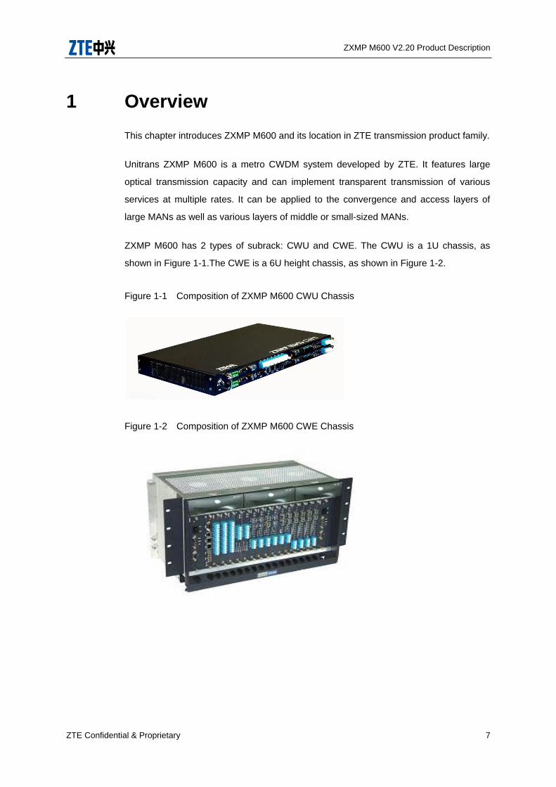
ZXMP M600 has 2 types of subrack: CWU and CWE. The CWU is a 1U chassis, as
shown in Figure 1-1.The CWE is a 6U height chassis, as shown in Figure 1-2.
Figure 1-1 Composition of ZXMP M600 CWU Chassis
Figure 1-2 Composition of ZXMP M600 CWE Chassis
ZXMP M600 V2.20 Product Description
8 ZTE Confidential & Proprietary
2 Highlight Features
2.1 Large Capacity and High Integration
A CWU chassis can be used to implement the bidirectional transmission of 4+1
wavelengths by building an optical terminal multiplexer (OTM) node.
Two piled CWU chassis can implement the bi-directional transmission of 8+1
wavelengths by building an OTM node. “+1” refers to the 1310 nm optical supervisory
channel (OSC).
A CWU chassis can implement the bidirectional transmission of 2+1 wavelengths by
building an optical add/drop multiplexer (OADM) node.
A CWE chassis can implement the bidirectional transmission of 18 wavelengths at most.
The maximum rate of each channel can reach 2.5Gbit/s. The wavelength selection and
wavelength interval are in strict compliance with ITU-T Recommendation G.694.2.
2.2 Rich service access types
ZXMP M600 adopts O/E/O conversion technology to convert the optical access signal to
the wavelength signal complying with ITU-T Recommendation G.694.2.
• Multi-rate services access, including STM-1, STM-4 and STM-16.
• Continuous-rate services access (10 Mbit/s ~ 2.7 Gbit/s), such as E3, T3/DS3, E4,
STM-0/STM-1/STM-4/STM-16, FE, GbE, FC, 2FC, ESCON and DVB-ASI.
2.3 Various Service Convergence
ZXMP M600 can multiplex (converge) and demultiplex low rate signals.
• Each ETM card can multiplex 2 channels of GE signals.
ZXMP M600 V2.20 Product Description
ZTE Confidential & Proprietary 9
2.4 Flexible Networking Modes
Functionality of ZXMP M600 can be changed from OTM to OADM by choosing different
combination of functional modules, making it more flexible for complicated network
topologies, such as chain, ring and tangent networks.
In addition, it supports flexible wavelengths add/drop from 1 to 18 and smooth upgrade
contributing to its modular architecture.
2.5 Powerful Protection Capability
ZXMP M600 supports 1+1 link optical multiplex section protection, and 1+1 optical
channel protection in ring network.
The switch criteria is the LOS signal of receiving module. The switch operation is
achieved by electrical cross switch chip.
2.6 Perfect Transmission of Supervision Information
ZXMP M600 provides four 100BASE-FX OSC interfaces and two 10/100M Ethernet
interfaces. The OSC transmission limit is 80 km.
2.7 Convenient Maintenance
• Support installation in the front.
• Support replaceable small form-factor pluggable (SFP) optical modules.
• Support mixed plug and hot plug of the usable cards in CWU and CWE chassis
except of the PCW and NCP card.
• Support the front installation and hot plug of the fan in the chassis.

ZXMP M600 V2.20 Product Description
10 ZTE Confidential & Proprietary
2.8 Flexible chassis design
• CWU chassis with the height of 1U (44 mm) and 6 card slots. It supports desktop
installation or IEC/ETSI standard 19’’ cabinet installation in the front or back.
• CWE chassis with the height of 6U (265.9 mm) and 18 card slots. It supports
IEC/ETSI standard 19’’ cabinet installation in the front or back.
• The CWE chassis is usually allocated alone in the station with concentrative
services.
2.9 Multiple Power Access Modes
• The input power supply of CWU chassis can be -48 V/-60 V DC, or 220 V (50
Hz)/110 V (60 Hz) AC. An external adapter is needed for AC input.
• The input power supply of CWE chassis is -48 V/-60 V DC.
• Two power supply cards in chassis guarantee reliable power supply for the system
by carrying out 1+1 hot backup.
2.10 Optional OSC/ESC
ZXMP M600 provides four OSC. It can also provide ESC electrical supervision function.
2.11 L2 Switching
ZXMP M600 supports L2 switching function, SFE/SOFE card can Multiplex 2 channels of
GE signals and 8 channels of FE, which can save wavelengths tremendously.
ZXMP M600 V2.20 Product Description
ZTE Confidential & Proprietary 11
2.12 Distinctive Network Management System
ZXONM E300 network management system, used for the ZXMP M600, provides friendly
user interfaces and is easy to operate.
It supports multi-layer management of NE layer, NE management layer and network
management layer with the following features:
• The system has good expandability and adaptability, for the object-oriented
technology is adopted in design and development to build up the C/S architecture with
three separated layers (interface layer, service layer and data layer).
• Complex networks can be constructed easily with the standard L2 layer Ethernet
switching technology.
• The usability and reliability are highly improved by the real-time data
synchronization and automatic switching between main station and sub-station.
• Upgrade without interrupting the service of foreground/background network
management software and embedded software of all cards.
• Unified management of CWDM/DWDM/SDH equipment.
ZXMP M600 can also use NetNumenTM U31 network management system.
• The system adopts the distributed, multi-process and modular design. It has such
management function as configuration management, fault management, performance
management, maintenance management, path management, security management,
system management and report management.
• It supports such services as TDM, ATM, Ethernet, PTN, WDM and intelligent
services.
• While assuring transport equipment functions, the system can manage and control
NE and regional networks.
ZXMP M600 V2.20 Product Description
12 ZTE Confidential & Proprietary
• The system adopts multiple network management technologies, complies with
ITU-T TMN ideas, collects the industry-leading NM software development experience
and provides powerful management functions and flexible networking.
• It supports the standard northbound interface.
ZXMP M600 V2.20 Product Description
ZTE Confidential & Proprietary 13
3 Functionality
3.1 System Function
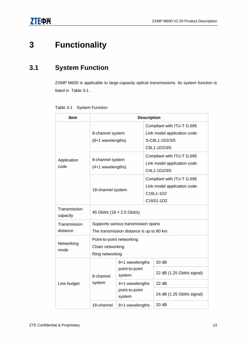
ZXMP M600 is applicable to large-capacity optical transmissions. Its system function is
listed in Table 3-1 .
Table 3-1 System Function
Item Description
Application
code
8-channel system
(8+1 wavelengths)
Compliant with ITU-T G.695
Link model application code:
S-C8L1-1D2/3/5
C8L1-1D2/3/5
8-channel system
(4+1 wavelengths)
Compliant with ITU-T G.695
Link model application code:
C4L1-1D2/3/5
18-channel system
Compliant with ITU-T G.695
Link model application code:
C16L1-1D2
C16S1-1D2
Transmission
capacity 45 Gbit/s (18 × 2.5 Gbit/s)
Transmission
distance
Supports various transmission spans
The transmission distance is up to 80 km.
Networking
mode
Point-to-point networking
Chain networking
Ring networking
Line budget
8-channel
system
8+1 wavelengths
point-to-point
system
20 dB
22 dB (1.25 Gbit/s signal)
4+1 wavelengths
point-to-point
system
22 dB
24 dB (1.25 Gbit/s signal)
18-channel 8+1 wavelengths 20 dB

ZXMP M600 V2.20 Product Description
14 ZTE Confidential & Proprietary
Item Description
system point-to-point
system 22 dB (1.25 Gbit/s signal)
4+1 wavelengths
point-to-point
system
22 dB
24 dB (1.25 Gbit/s signal)
18 wavelengths
Point-to-point
system
19 dB
21 dB (1.25 Gbit/s
signal)
Fiber type Compliant with ITU-T G.652, G.653 and G.655
Wavelength Compliant with ITU-T G694.2
Configuration
An OTM node consisting of a CWU chassis supports
bidirectional transmission of 4+1 wavelengths.
“+1” refers to 1310 nm optical supervisory channel.
An OTM node consisting of two piled CWU chassis supports
bidirectional transmission of 8+1 wavelengths.
“+1” refers to 1310 nm optical supervisory channel.
An OADM node consisting of a CWU chassis supports
bidirectional transmission of 2+1 wavelengths, including the
adding/dropping of two fixed wavelengths and the
pass-through of other wavelengths.
“+1” refers to 1310 nm optical supervisory channel.
An OADM node consisting of multiple CWU or CWE chassis
supports the adding/dropping of 1-18 wavelengths.
Protection OCH 1+1 protection
OMS 1+1 protection
Mean time
between failure
(MTBF)
> 50 000 hours/channel
Interface Supports open interfaces or integrated interfaces
Note:
• “1U chassis” refers to the ZXMP M600 chassis with the height of 44 mm.
ZXMP M600 V2.20 Product Description
ZTE Confidential & Proprietary 15
• “+1” refers to the 1310 nm optical supervisory channel.
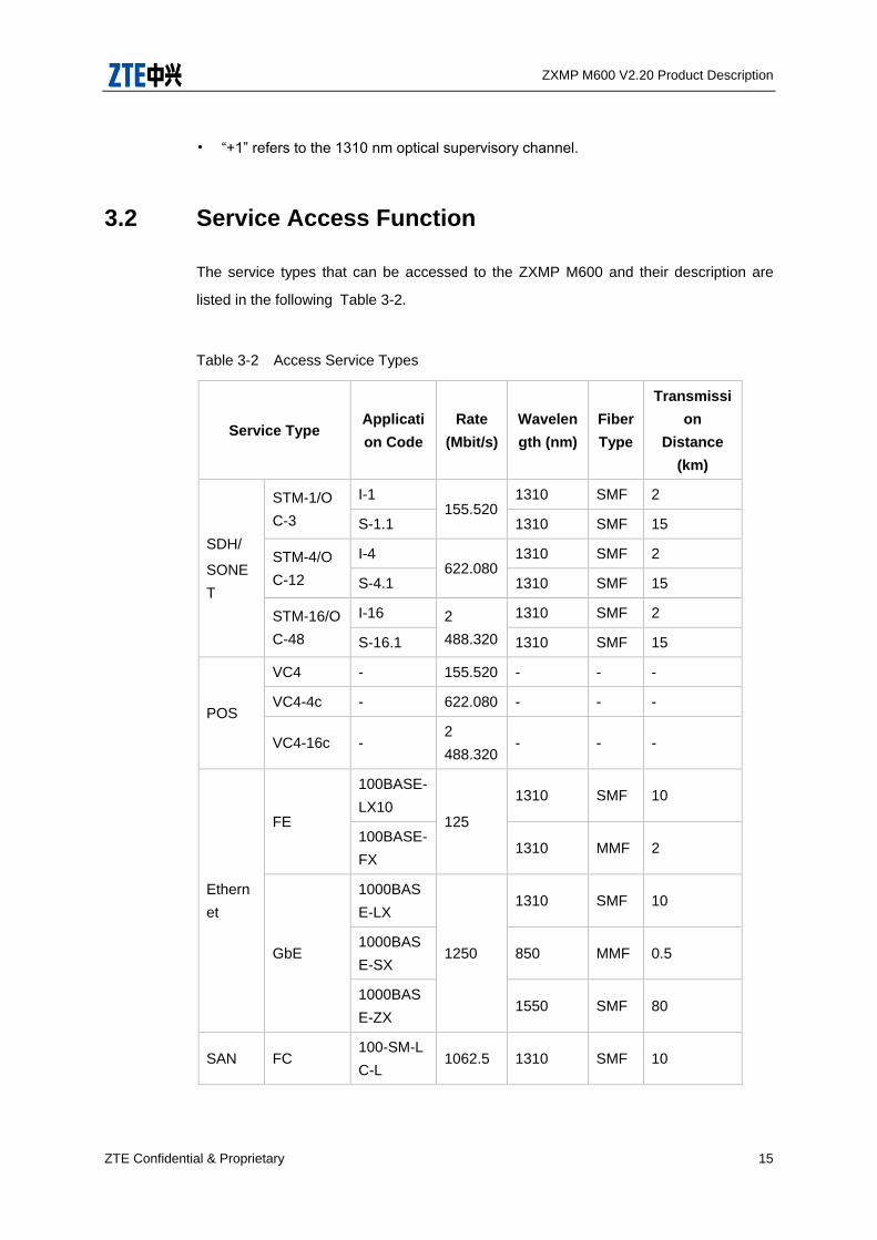
3.2 Service Access Function
The service types that can be accessed to the ZXMP M600 and their description are
listed in the following Table 3-2.
Table 3-2 Access Service Types
Service Type Applicati
on Code
Rate
(Mbit/s)
Wavelen
gth (nm)
Fiber
Type
Transmissi
on
Distance
(km)
SDH/
SONE
T
STM-1/O
C-3
I-1 155.520
1310 SMF 2
S-1.1 1310 SMF 15
STM-4/O
C-12
I-4 622.080
1310 SMF 2
S-4.1 1310 SMF 15
STM-16/O
C-48
I-16 2
488.320
1310 SMF 2
S-16.1 1310 SMF 15
POS
VC4 - 155.520 - - -
VC4-4c - 622.080 - - -
VC4-16c - 2
488.320 - - -
Ethern
et
FE
100BASE-
LX10 125
1310 SMF 10
100BASE-
FX 1310 MMF 2
GbE
1000BAS
E-LX
1250
1310 SMF 10
1000BAS
E-SX 850 MMF 0.5
1000BAS
E-ZX 1550 SMF 80
SAN FC 100-SM-L
C-L 1062.5 1310 SMF 10
ZXMP M600 V2.20 Product Description
16 ZTE Confidential & Proprietary
Service Type Applicati
on Code
Rate
(Mbit/s)
Wavelen
gth (nm)
Fiber
Type
Transmissi
on
Distance
(km)
100-M5-S
N-I 850 MMF 0.5
2FC
200-SM-L
C-L 2125
1310 SMF 10
200-M5-L
C-I 850 MMF 0.3
ESCON - 200 1310 MMF 2
OTN
P1I1-1D1
2666 .0
57
1310 SMF 2
P1S1-1D1 1310 SMF 15
P1L1-1D1 1310 SMF 40
P1S1-1D2 1310 SMF 15
Other
Optical
Interfac
es
DVB-ASI - 270 - - -
E3 - 34.368 - - -
T3/DS3 - 44.736 - - -
E4 - 139.264 - - -
Future
service -
10~2
700 - - -
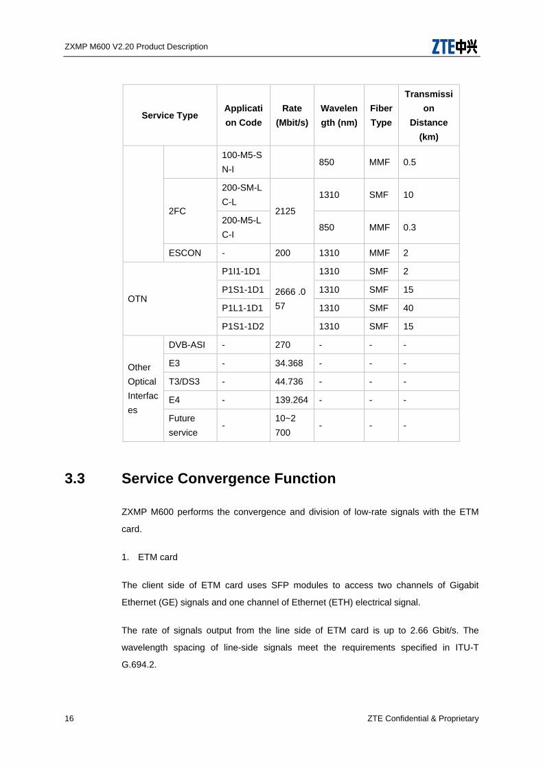
3.3 Service Convergence Function
ZXMP M600 performs the convergence and division of low-rate signals with the ETM
card.
1. ETM card
The client side of ETM card uses SFP modules to access two channels of Gigabit
Ethernet (GE) signals and one channel of Ethernet (ETH) electrical signal.
The rate of signals output from the line side of ETM card is up to 2.66 Gbit/s. The
wavelength spacing of line-side signals meet the requirements specified in ITU-T
G.694.2.

ZXMP M600 V2.20 Product Description
ZTE Confidential & Proprietary 17
Four types of ETM card are available: ETMb, ETMs, ETMp and ETMg;
• ETMb
Single-path bidirectional terminal ETM card without protection function. Its aggregate
optical interface uses an unpluggable optical module.
• ETMs
Single-path bidirectional terminal ETM card without protection function. Its aggregate
optical interface uses a pluggable SFP optical module.
• ETMp
Single-path bidirectional terminal ETM card with protection function.
• ETMg
Single-path bidirectional regenerator ETM card without protection function.
3.4 Protection Function
ZXMP M600 supports 1+1 link optical multiplex section protection and 1+1 optical
channel protection in ring network.
1. 1+1 Link Optical Multiplex Section Protection
The OP card performs 1+1 optical multiplex section protection.
Figure 3 illustrates the fiber connection of the protection.
Figure 3-1 Fiber Connection of 1+1 Optical Multiplex section Protection
OMD
OP
OMD
OTU
OP
OTU
OTU
OTU
OTU
OTU
Protection
n
n
Protection
Working
Working
Note:
ZXMP M600 V2.20 Product Description
18 ZTE Confidential & Proprietary
The OTU card in Figure 3-1can be replaced by ETM card according to actual situation.
• Working Principle
The OP card supervises the main optical channel.
The protection switching is carried out by the optical switch on the OP card when the
switching condition is met. The switching time is less than 50 ms.
• Switching Condition
The NMS gives the protection switching order when the OP card detects the LOS alarm
(the optical power is less than -25 dBm).
The OP and OTU card with protection function can perform 1+1 optical channel
protection in ring network on client side and line side respectively.
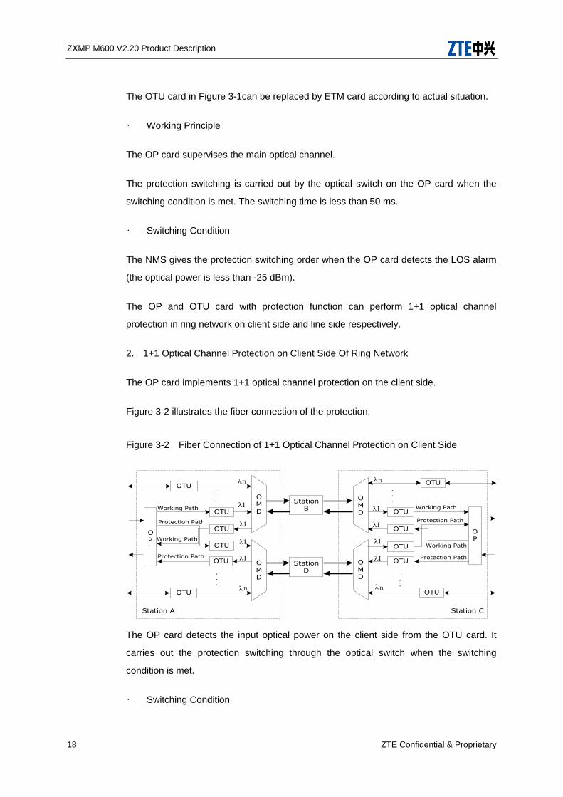
2. 1+1 Optical Channel Protection on Client Side Of Ring Network
The OP card implements 1+1 optical channel protection on the client side.
Figure 3-2 illustrates the fiber connection of the protection.
Figure 3-2 Fiber Connection of 1+1 Optical Channel Protection on Client Side
StationB
StationD
OMD
OMD
Working Path
Working Path
Protection Path
Protection Path
n
n...
.
.
.
OTU
OTU
OTU
OTU
OTU
OTU
OP
Station C
OMD
OMD
OP
Working Path
Working Path
Protection Path
Protection Path
.
.
.
.
.
.
n
n
OTU
OTU
OTU
OTU
OTU
OTU
Station A
The OP card detects the input optical power on the client side from the OTU card. It
carries out the protection switching through the optical switch when the switching
condition is met.
• Switching Condition
ZXMP M600 V2.20 Product Description
ZTE Confidential & Proprietary 19
The NMS gives the protection switching order when the input optical power from the OTU
card is less than –25 dBm.
• Advantage
The protection switching will not be disabled when one of the OTU card is at fault.
• Drawback
The cost is high with the demand of additional cards.
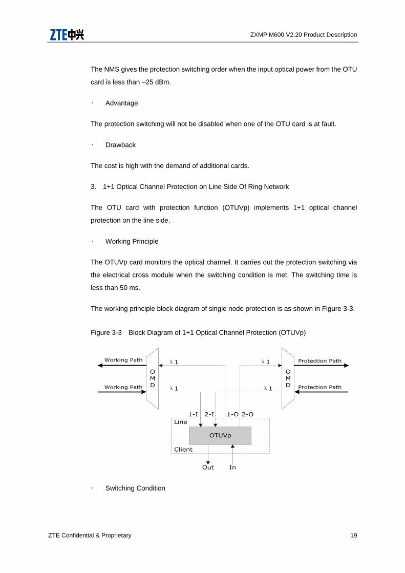
3. 1+1 Optical Channel Protection on Line Side Of Ring Network
The OTU card with protection function (OTUVp) implements 1+1 optical channel
protection on the line side.
• Working Principle
The OTUVp card monitors the optical channel. It carries out the protection switching via
the electrical cross module when the switching condition is met. The switching time is
less than 50 ms.
The working principle block diagram of single node protection is as shown in Figure 3-3.
Figure 3-3 Block Diagram of 1+1 Optical Channel Protection (OTUVp)
OMD
OMD
Working Path
Protection Path
Protection Path
Working Path
OTUVp
Out In
Client
Line
1-I 2-I 1-O 2-O
λ1 λ1
λ1λ1
• Switching Condition

ZXMP M600 V2.20 Product Description
20 ZTE Confidential & Proprietary
The NMS gives the protection switching order when the line receiving module on the
OTUVp card reports the LOS alarm.
• Advantage
The cost is low. And the OTU card performs the protection function.
• Drawback
The protection will be disabled when the OTUVp card is at fault.
3.5 Communication and Supervision Functions
1. Communication between NMS and Access Point
This sub-section describes the communication between the network management
system and access nodes from two aspects: software and hardware.
2. Software Interface
The software interfaces between the NCP card used in ZXMP M600 equipment and the
NMS include Qx, CLI and SNMP.
• Qx: the communication interface between ZXMP M600 and ZXONM E300 NMS/
NetNumenTM U31 developed by ZTE CORPORATION. It complies with TCP/IP.
• CLI: command line interface. User can use Telnet command to login the network
element and give orders in the command line interface.
• SNMP: simple network management protocol. It provides communication interfaces
between the ZXMP M600 and NMS developed by other manufacturers.
3. Hardware Interface
The access node is connected to the NMS via the Ethernet interface on the NCP card.
The identifier of Ethernet interface is ETH1 or ETH2.
ZXMP M600 V2.20 Product Description
ZTE Confidential & Proprietary 21
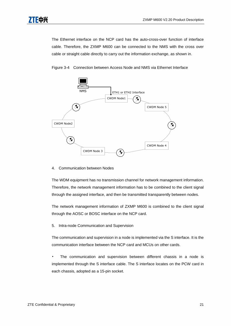
The Ethernet interface on the NCP card has the auto-cross-over function of interface
cable. Therefore, the ZXMP M600 can be connected to the NMS with the cross over
cable or straight cable directly to carry out the information exchange, as shown in.
Figure 3-4 Connection between Access Node and NMS via Ethernet Interface
CWDM Node1
CWDM Node2
CWDM Node 3
CWDM Node 4
CWDM Node 5
NMS ETH1 or ETH2 Interface
4. Communication between Nodes
The WDM equipment has no transmission channel for network management information.
Therefore, the network management information has to be combined to the client signal
through the assigned interface, and then be transmitted transparently between nodes.
The network management information of ZXMP M600 is combined to the client signal
through the AOSC or BOSC interface on the NCP card.
5. Intra-node Communication and Supervision
The communication and supervision in a node is implemented via the S interface. It is the
communication interface between the NCP card and MCUs on other cards.
• The communication and supervision between different chassis in a node is
implemented through the S interface cable. The S interface locates on the PCW card in
each chassis, adopted as a 15-pin socket.
ZXMP M600 V2.20 Product Description
22 ZTE Confidential & Proprietary
• The internal communication in the same chassis is implemented through the S
interface bus on the chassis backcard.
3.6 Alarm Output Function
ZXMP M600 provides alarm output function. It can output critical alarm, major alarm and
ring trip signals to the row-first cabinet in the equipment room. The alarm output interface
of ZXMP M600 is on the NCP card in the main CWU chassis, adopted as an RJ11 socket.
The interface identifier is ALM.

ZXMP M600 V2.20 Product Description
ZTE Confidential & Proprietary 23
4 System Architecture
4.1 Description of System Functional Platform
The structure of the ZXMP M600 equipment is shown in Figure 4-1
Figure 4-1 Functional Block of the ZXMP M600 Equipment
ZXMP M600 Metro CWDM equipment
OTM equipment and
OADM equipment
ZXONM E300 /
NetNumenTM
U31 NMS
Hardware system Network management software system
Mo
nito
r platfo
rm
Op
tical transfer
platfo
rm
Mu
ltiplex
ing/
dem
ultip
lexin
g p
latform
Serv
ice con
verg
ence
platfo
rm
Po
wer su
pp
ly
platfo
rm
Sy
stem
man
agem
ent
Co
nfig
uratio
n
man
agem
ent
Fau
lt
man
agem
ent
Perfo
rman
ce
man
agem
ent
Main
tenan
ce
man
agem
ent
Secu
rity
man
agem
ent
ZXMP M600 consists of hardware system and NM software system, which are
independent of each other and work coordinately.
4.2 Structure of Hardware System
The hardware system of ZXMP M600 includes an optical transfer platform, service
convergence system, multiplexing/demultiplexing platform, monitor platform and power
supply platform.
1. Optical transfer platform
It adopts the optical/ electrical/ optical conversion mode to implement wavelength
conversion of service signals and line signals.

ZXMP M600 V2.20 Product Description
24 ZTE Confidential & Proprietary
The service signals include multi-service signals with a rate lower than 2.5Gbit/s
and with the maximum rate being 2.5Gbit/s.
The line signals meet the requirements specified in ITU-T recommendation G.694.2.
2. Service convergence platform
It converges multiple channels of low rate signals into one wavelength for transmission
and implements the reserve process.
The low rate signals include standard STM-1, STM-4 signals with the maximum rate
being 2.5Gbit/s on the line.
3. Multiplexing/demultiplexing platform
It includes a multiplexing part and a demultiplexing part.
i Multiplexing part: It couples multiple channels of optical signals with different
wavelengths from the optical transfer platform and service convergence platform to a
piece of optical fiber for transmission.
ii Demultiplexing part: It divides the multiplexing optical signals from the line side
according to their different wavelengths and sends them to different optical transfer
platform and service convergence platform.
4. Monitor platform
• Collecting, processing and reporting the configuration, alarm and performance
information of the various platforms
• Receiving the command from the NMS and transferring it to the destination card
• Using a specified monitoring optical channel to transparently transmit the network
management information. The wavelength of the monitoring channel can be either
1310nm or 1510nm.
5. Power supply platform
It converts in DC input into +5V or -48V DC power to provide power for various platforms.
ZXMP M600 V2.20 Product Description
ZTE Confidential & Proprietary 25
Options –48V and –60V are available for DC power supply, and 1+1 warm backup are
practicable.
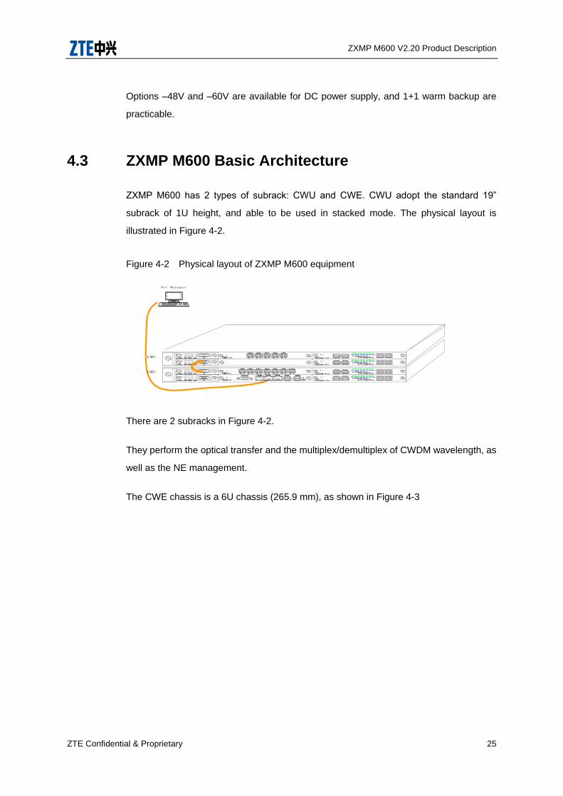
4.3 ZXMP M600 Basic Architecture
ZXMP M600 has 2 types of subrack: CWU and CWE. CWU adopt the standard 19”
subrack of 1U height, and able to be used in stacked mode. The physical layout is
illustrated in Figure 4-2.
Figure 4-2 Physical layout of ZXMP M600 equipment
Net Manager
NCP
AOSC BOSCETH1
RSTL3
CWU
CWU
ETH2
UPG Ch1 Ch2 Ch3 Line
OMD
Ch4Ch0
5-1 O I O I O I O I O I O I O I
Ch6 Ch7 Ch8
OMD
UPGCh5
4-5 O I O I O I O I O I
ALMRS232
PCWAS SGND PGND -48V
PCWAS SGND PGND -48V
PCWAS SGND PGND -48V
PCWAS SGND PGND -48Vh
OTUqmL-1-2
C1T C1R L1T L1RC2T C2R L2T L2R
OTU
C1T C1R L1T L1RC2T C2R L2T L2R
OTU
C1T C1R L1T L1RC2T C2R L2T L2R
OTU
C1T C1R L1T L1RC2T C2R L2T L2R
qmL-3-4
qmL-5-6
qmL-7-8
There are 2 subracks in Figure 4-2.
They perform the optical transfer and the multiplex/demultiplex of CWDM wavelength, as
well as the NE management.
The CWE chassis is a 6U chassis (265.9 mm), as shown in Figure 4-3

ZXMP M600 V2.20 Product Description
26 ZTE Confidential & Proprietary
Figure 4-3 6U Chassis Architecture (CWE)
1. Lug 2. Fiber Cable Reel-in Box 3. Fan Unit 4. Card
1. CWU Shelf
Figure 4-4 illustrates the card position arrangement in the CWU chassis. The number
following the card name represents the slot number.
Figure 4-4 Card Position Arrangement in CWU Chassis
OAD/OMD/OP/OTUV /OTUE/DSA/ETM ⑤NCP ⑤
OAD/OMD/OP/OTUV /OTUE/DSA/ETM ⑤OAD/OMD/OP/OTUV /OTUE/DSA/ETM ⑤PCW ⑤
PCW ⑤
Table 4-1 lists the slots in the CWU chassis and corresponding pluggable cards.
Table 4-1 Slots and Pluggable Cards in CWU Chassis
Slot No. Pluggable Card Remark
1, 2 PCW
PCWAS and PCWCS cards are optional.
Only two cards of the same type can be
inserted in one chassis.
ZXMP M600 V2.20 Product Description
ZTE Confidential & Proprietary 27
Slot No. Pluggable Card Remark
3 NCP
NCP card can only be configured in the
master CWU chassis at each site.
For the other CWU chassis at the site, slot 3
can be used for OTUV, OMD, OAD or OP
card.
4, 5, 6 OTUV, OMD, OAD,
OP and ETM
Each card can be inserted in any one of
these slots.
One card occupies one slot.
3-4, 5-6 SFE/SOFE
Each SFE/SOFE card occupies two slots,
one on the upper and the other on the lower
of the chassis.
In a master CWU chassis, SFE/SOFE cards
can only be plugged into slot 5 and 6 since
NCP card occupies slot 3.
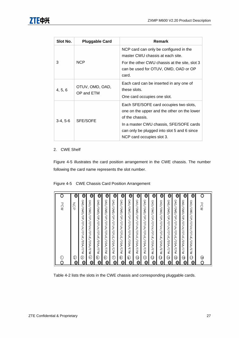
2. CWE Shelf
Figure 4-5 illustrates the card position arrangement in the CWE chassis. The number
following the card name represents the slot number.
Figure 4-5 CWE Chassis Card Position Arrangement
Table 4-2 lists the slots in the CWE chassis and corresponding pluggable cards.

ZXMP M600 V2.20 Product Description
28 ZTE Confidential & Proprietary
Table 4-2 Slots and Cards in CWE Chassis
Slot No. Pluggable Card Remark
1, 18 PCW
PCWAS and PCWCS cards are optional.
Only two cards of the same type can be
inserted in one chassis.
2 NCP -
3-17 OTUV, OMD, OAD, OP
and ETM
Each card can be inserted in any one of
these 15 slots.
One card occupies one slot.
3-17 SOFE, SFE Each SOFE/SFE card occupies any two
adjacent slots.
4.4 Functions and Classification of Cards
The names and applicable chassis of the cards of the ZXMP M600 equipment are shown
in Table 4-3.
Table 4-3 List of the ZXMP M600 Card Names
Unit/Card Name Code Full Name
Net control processor NCP Net Control Processor
Power card PCW Power Card for CWDM Unit
Optical transponder Unit OTUV Optical Transponder Unit
Optical Mux/Demux Card OMD Optical Mux/DeMux Card
Optical add/drop multiplexer OAD Optical Add/Drop Card
GE Service Convergence Card ETM GE Service Convergence Card
Fast Ethernet Switched and
Converged card SFE
Fast Ethernet Switched and
Converged card
Multiple cards can be plugged in the chassis to implement corresponding functions.
4.4.1 Optical Transponder Unit (OTUV)
The optical transponder unit, including OTUV card, implements the wavelength
conversion between service signal and line single through optical-electrical-optical
ZXMP M600 V2.20 Product Description
ZTE Confidential & Proprietary 29
(O/E/O) conversion. The line signal wavelength spacing meets the requirements of
G.694.2.
1. OTUV
Both the transmitting end and the receiving end of OTUV card employs 3R (Reshaping,
Reamplifying, Retiming) technology.
The client side of OTUV card uses Small-Form Factor Pluggable (SFP) module to access
traffic at any rate from 10 Mbit/s to 2.7 Gbit/s.
The line side of OTUV card uses laser optical module. The wavelength spacing of
line-side signals meet the requirements specified in ITU-T G.694.2.
OTUV card supports Automatic Power Shutdown (APSD) function.
The line side of OTUV card uses SFP module. The wavelength spacing of line-side
signals meet the requirements specified in ITU-T G.694.2.
4.4.2 Service Convergence Card
The service convergence cards converge multiple low-rate signals to one wavelength,
and implement the opposite procedure.
1. ETM card
The client side of ETM card uses SFP modules to access two channels of Gigabit
Ethernet (GE) signals and one channel of Ethernet (ETH) electrical signal.
2. SFE/SOFE card
SFE/SOFE card can Multiplex 2 channels of GE signals and 8 channels of FE with L2
switching function, which can save wavelengths tremendously.
4.4.3 Optical Mux/DeMux Card (OMD)
The OMD card multiplexes multiple optical signals with different wavelengths to transmit
over a single fiber, and divides the optical signal from the line side according to different
wavelength channels.

ZXMP M600 V2.20 Product Description
30 ZTE Confidential & Proprietary
4.4.4 Optical Add/Drop Card (OAD)
The OAD card adds and drops wavelengths at the OADM node.
4.4.5 Optical Protect Card (OP)
The OP card performs 1+1 protection function for the system. The 1+1 protection is
divided into optical multiplex section 1+1 protection and optical channel 1+1 protection
according to the position of the OP card in the system.
4.4.6 Net Control Processor (NCP)
1. Collect and process the configuration, alarm and performance information of all
network elements, and report the information to the network management system
(NMS).
2. Receive the command from NMS and transmit it to the destination card.
3. Transmit the network management information transparently through the assigned
optical supervisory channel.
4.4.7 Power Card for CWDM Unit (PCW)
The PCW card transforms external input power supply to +5 V DC or -48 V DC, supplying
all cards in the equipment. The external power supply can be DC and AC.
4.5 The NM Software System Structure
The unitrans ZXONM E300 uniform EMS/SNMS of optical network (ZXOMN E300 for
short) and NetNumenTM U31 are used for the ZXMP M600 to perform the software
management.
1. ZXONM E300
ZXONM E300 includes the following management functions.
• Fault Management
ZXMP M600 V2.20 Product Description
ZTE Confidential & Proprietary 31
• Performance Management
• Security Management
• Configuration Management
• Maintenance Management
• System Management
The ZXONM E300 consists of four layers:
• Device Layer
• Network Element Layer
• Network Element Management layer
• Sub-Network Management Layer
In addition, the ZXONM E300 can provide CORBA interface to the network management
layer.
Please refer to the ZXONM E300 manuals for detailed descriptions of the network
management software.
2. NetNumenTM U31
NetNumenTM U31 is the new generation transmission network management system fit for
the new development trend, which is oriented to service, make customer priority and
always try to pursuit excellence. It is the professional network management system for
telecommunication services supplier. It assures the core businesses are managed in a
safe, reliable and convenient operating environment.
NetNumenTM U31 is the network management system based on distributed, multi
process and plug-in design. It is the platform managing all ZTE’s optical transmission
products and supporting TDM, ATM, Ethernet, PTN, WDM and intelligent service. It
adopts multiple network management technologies, ITU-T TMN and e-Tom ideas in the
design and R&D. ZTE centralizes leading software development experience, so U31 has
powerful management and flexible networking capabilities.

ZXMP M600 V2.20 Product Description
32 ZTE Confidential & Proprietary
ZXMP M600 V2.20 Product Description
ZTE Confidential & Proprietary 33
5 Technical Specifications
5.1 System Indices
1. Compatible with Black-link and Black-box model.
2. Supporting open interfaces and integrated interfaces.
3. Application code: S-C8L1-1D2/3/5, C8L1-1D2/3/5, C4L1-1D2/3/5.
4. Supporting optical transmission of three fiber types: G.652, G.653 and G.655 fiber.
5. The 4+1 wavelengths system can be upgraded to 8+1 wavelengths system
smoothly. The highest transmission capacity is 45Gbit/s (18 × 2.5 Gbit/s).
6. ZXMP M600 can be configured as OTM or OADM equipment flexibly, supporting the
point-to-point, chain and ring networking architecture.
7. The maximum line attenuation of 4+1 wavelengths system does not exceed 22 dB.
The maximum line attenuation of 8+1 wavelength system does not exceed 20 dB,.
and that of an 18-channel system does not exceed 19 dB.
8. The wavelength spacing meets the requirement of ITU-T Recommendation G.694.2.
Note: The system does not support 1310 nm channel (“+1” channel) while using G.655
fiber in transmission, because its cut-off wavelength is 1450 nm.
5.2 Operating Wavelength
The operating wavelength of ZXMP M600 complies with ITU-T Recommendation
G.694.2. The special central wavelength and frequency used in multi-channel systems
are employed.
For the general fiber (G.652 A&B), the ZXMP M600 usually employs 8+1 wavelengths.
The wavelength spacing is 20 nm. “+1” refers to the additional channel in 1310 nm
window.
ZXMP M600 V2.20 Product Description
34 ZTE Confidential & Proprietary
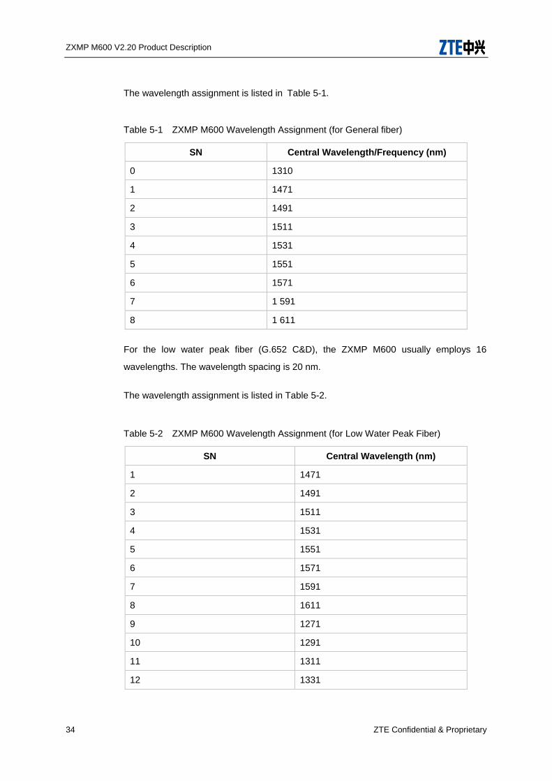
The wavelength assignment is listed in Table 5-1.
Table 5-1 ZXMP M600 Wavelength Assignment (for General fiber)
SN Central Wavelength/Frequency (nm)
0 1310
1 1471
2 1491
3 1511
4 1531
5 1551
6 1571
7 1 591
8 1 611
For the low water peak fiber (G.652 C&D), the ZXMP M600 usually employs 16
wavelengths. The wavelength spacing is 20 nm.
The wavelength assignment is listed in Table 5-2.
Table 5-2 ZXMP M600 Wavelength Assignment (for Low Water Peak Fiber)
SN Central Wavelength (nm)
1 1471
2 1491
3 1511
4 1531
5 1551
6 1571
7 1591
8 1611
9 1271
10 1291
11 1311
12 1331

ZXMP M600 V2.20 Product Description
ZTE Confidential & Proprietary 35
SN Central Wavelength (nm)
13 1351
14 1371
15 1391
16 1411
17 1431
18 1451
5.3 Mechanical Indices
The dimension and weight parameters of the component parts of ZXMP M600 are listed
in Table 5-3.
Table 5-3 Dimensions and Weight of Structural Parts
Structural Part Dimensions (mm) Weight
(kg)
Applicable
Chassis
CWU chassis
Desktop: 44 × 441.8 ×
242 (H × W ×D)
IEC Cabinet: 44 ×
482.6 × 242 (H × W
×D)
ETSI Cabinet: 44 ×
535 × 242 (H × W ×D)
Net: 3.3
Full: 7.7 -
CWE chassis
IEC Cabinet: 265.9 ×
482.6 × 270 (H × W
×D)
ETSI Cabinet: 265.9 ×
535 × 270 (H × W ×D)
Net: 9
Full: 16 -
Fan plug-in box 41.2 × 30.6 × 222 (H ×
W ×D) - CWU
Independent fan unit 44 × 145 × 247.5 (H ×
W ×D) - CWE
ZXMP M600 V2.20 Product Description
36 ZTE Confidential & Proprietary
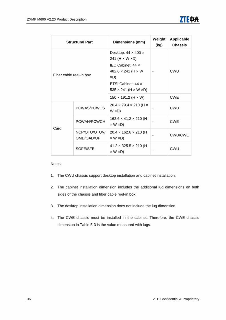
Structural Part Dimensions (mm) Weight
(kg)
Applicable
Chassis
Fiber cable reel-in box
Desktop: 44 × 400 ×
241 (H × W ×D)
IEC Cabinet: 44 ×
482.6 × 241 (H × W
×D)
ETSI Cabinet: 44 ×
535 × 241 (H × W ×D)
- CWU
150 × 191.2 (H × W) CWE
Card
PCWAS/PCWCS 20.4 × 79.4 × 210 (H ×
W ×D) - CWU
PCWAH/PCWCH 162.6 × 41.2 × 210 (H
× W ×D) - CWE
NCP/OTU/OTUV/
OMD/OAD/OP
20.4 × 162.6 × 210 (H
× W ×D) - CWU/CWE
SOFE/SFE 41.2 × 325.5 × 210 (H
× W ×D) - CWU
Notes:
1. The CWU chassis support desktop installation and cabinet installation.
2. The cabinet installation dimension includes the additional lug dimensions on both
sides of the chassis and fiber cable reel-in box.
3. The desktop installation dimension does not include the lug dimension.
4. The CWE chassis must be installed in the cabinet. Therefore, the CWE chassis
dimension in Table 5-3 is the value measured with lugs.
ZXMP M600 V2.20 Product Description
ZTE Confidential & Proprietary 37
5.4 System Component Indices
5.4.1 OMD Specifications
ZXMP M600 provides various OMD cards, including OMD5-1, OMD4-5, OMDS,
OMD4-1US, OMD4-5U, OMD4-9U, OMD5-14U, OMD4-5US, OMD4-9US and
OMD5-14US.
Among these cards, OMD5-1, OMD4-5 and OMDS cards are used in 8-channel systems;
while the other cards are used in 18-channel systems.
The following introduces the naming rule and available interfaces of these OMD cards.
• OMD5-1/OMD4-5 cards
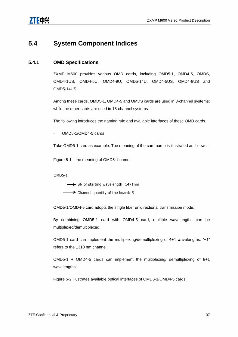
Take OMD5-1 card as example. The meaning of the card name is illustrated as follows:
Figure 5-1 the meaning of OMD5-1 name
OMD5-1
Channel quantity of the board: 5
SN of starting wavelength: 1471nm
OMD5-1/OMD4-5 card adopts the single fiber unidirectional transmission mode.
By combining OMD5-1 card with OMD4-5 card, multiple wavelengths can be
multiplexed/demultiplexed.
OMD5-1 card can implement the multiplexing/demultiplexing of 4+1 wavelengths. “+1”
refers to the 1310 nm channel.
OMD5-1 + OMD4-5 cards can implement the multiplexing/ demultiplexing of 8+1
wavelengths.
Figure 5-2 illustrates available optical interfaces of OMD5-1/OMD4-5 cards.

ZXMP M600 V2.20 Product Description
38 ZTE Confidential & Proprietary
Figure 5-2 Optical Interfaces of OMD5-1/OMD4-5 Cards
Co
up
ler
MUX
Co
up
ler
DE
MUX
MUX UPG/O
DE
MUX
OMD5-1
1551
1571
1591
1611
Line/I
UPG
CH1
CH2
CH3
CH4
CH0
/I
/I
/I
/I
/I
/I
1471
1491
1511
1531
1310
UPG
CH1
CH2
CH3
CH4
CH0
/O
/O
/O
/O
/O
/O
1471
1491
1511
1531
1310
CH5
CH6
CH7
CH8
/I
/I
/I
/I
1551
1571
1591
1611
CH5
CH6
CH7
CH8
/O
/O
/O
/O
Line/O
OMD4-5
UPG/I
Note: UPG - Upgrade interface /I - Input
Line - Line interface
CH0 - 1310 nm
/O - Output
• OMDS card
The line optical interface of OMDS card adopts the single fiber bidirectional transmission
mode.
Figure 5-3 illustrates available optical interfaces of OMDS card.
Figure 5-4 Optical Interfaces of OMDS Card
MUX
/
DEMUX
1471nm
1491nm
1511nm
1531nm
1551nm
1571nm
1591nm
1611nm
Couple
r
Line
1451nm
1310nm
MUX
/
DEMUX
1471nm
1491nm
1511nm
1531nm
1551nm
1571nm
1591nm
1611nm
Couple
r
Line
1451nm
1310nm
OMDS OMDS
Note: Line - Line optical interface
1310nm, 1451nm - Wavelength of optical supervisory channel
1471nm to 1611nm - Operating wavelengths
ZXMP M600 V2.20 Product Description
ZTE Confidential & Proprietary 39
OMD4-1US/OMD4-5U/OMD4-9U/OMD5-14U/OMD4-5U/OMD4-9U/OMD5-14U
cards
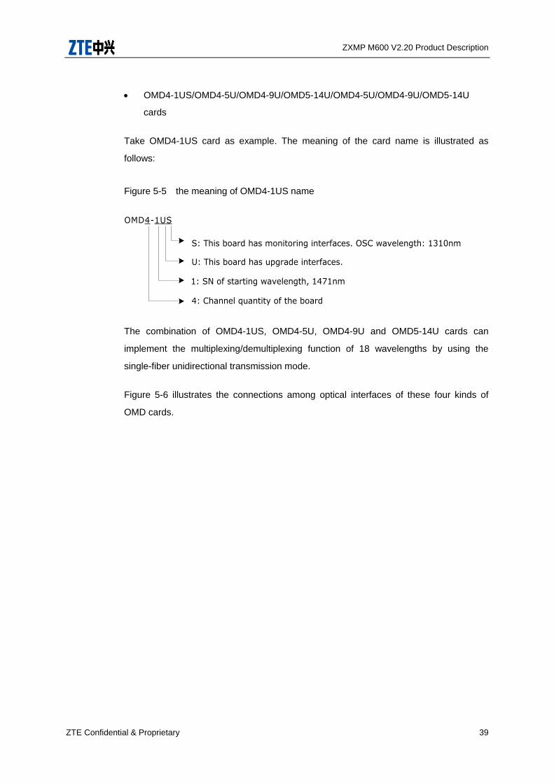
Take OMD4-1US card as example. The meaning of the card name is illustrated as
follows:
Figure 5-5 the meaning of OMD4-1US name
OMD4-1US
4: Channel quantity of the board
1: SN of starting wavelength, 1471nm
U: This board has upgrade interfaces.
S: This board has monitoring interfaces. OSC wavelength: 1310nm
The combination of OMD4-1US, OMD4-5U, OMD4-9U and OMD5-14U cards can
implement the multiplexing/demultiplexing function of 18 wavelengths by using the
single-fiber unidirectional transmission mode.
Figure 5-6 illustrates the connections among optical interfaces of these four kinds of
OMD cards.

ZXMP M600 V2.20 Product Description
40 ZTE Confidential & Proprietary
Figure 5-6 Optical Interfaces of OMD4-9U/OMD4-1US/OMD4-5U/OMD5-14U Cards
Line/O
Line/I
UPG
......
OMD5-14U
OMD4-9U
Line/O
Line/I
......
1271nm/Ito 1351nm/I
1271nm/Oto 1351nm/O
1311nm/O
Line/O
Line/I
UPGR...
...
1551nm/Ito 1611nm/I
1551nm/Oto 1611nm/O
OMD4-5U
OMD4-1US
Line/O
Line/I
......
1471nm/Ito 1531nm/I
1471nm/Oto 1531nm/O
1311nm/I
UPGB
Couple
r
MUX/DEMUX
MUX/DEMUX
MUX/DEMUX
MUX/DEMUX
1371nm/Ito 1451nm/I
1371nm/Oto 1451nm/O
The main performance parameters of ZXMP M600’s OMD cards are listed in Table
5-4,Table 5-5,Table 5-6.
Table 5-4 Performance Parameters of OMD5-1/OMD4-5/OMDS Cards
Parameter Unit OMD5-1 OMD4-5 OMDS
CWDM
central wavelength C nm
1471
1491
1511
1531
1310
1551
1571
1591
1611
1471/1491
1511/1531
1551/1571
1591/1611
1310/1451
CWDM [email protected] nm C ±6.5 C ±6.5 C ±6.5
Insertion
Loss (with
connector)
Line- CWDM dB ≤2 ≤3.5 ≤3.5
Line -UPG dB ≤2 - -
Line-1310nm/
1451nm dB ≤1 - ≤1

ZXMP M600 V2.20 Product Description
ZTE Confidential & Proprietary 41
Parameter Unit OMD5-1 OMD4-5 OMDS
Isolation
CWDM
channel to
adjacent
channel
dB
DEMUX:
≥30
MUX: NA
DEMUX:
≥30
MUX: NA
DEMUX:
≥30
MUX: NA
CWDM
channel to
non-adjacent
channel
dB
DEMUX:
≥45
MUX: NA
DEMUX:
≥45
MUX: NA
DEMUX:
≥45
MUX: NA
Upgrade
interface to
CWDM
DEMUX
signal
dB
DEMUX:
≥12
MUX: NA
- -
Return loss dB ≥40 ≥40 ≥40
Table 5-5 Performance Parameters of OMD4-1US/OMD4-5US/OMD4-9US/
OMD5-14US Cards
Parameter Unit OMD4-1
US
OMD4-5U
S
OMD4-9U
S
OMD5-14
US
CWDM
central wavelength C nm
1471
1491
1511
1531
1311
1551
1571
1591
1611
1311
1271
1291
1331
1351
1311
1371
1391
1411
1431
1451
1311
CWDM
[email protected] nm C ±6.5 C ±6.5 C ±6.5 C ±6.5
Insertion
loss (with
connector
)
Line-
CWDM dB ≤2.3 ≤2.3 ≤2.3 ≤2.3
Line-
UPG dB
≤2.2
(red
ribbon)
≤1.5
(blue
ribbon)
≤2.0 ≤1.8 ≤2.4

ZXMP M600 V2.20 Product Description
42 ZTE Confidential & Proprietary
Parameter Unit OMD4-1
US
OMD4-5U
S
OMD4-9U
S
OMD5-14
US
Line-131
1nm dB ≤1.2 ≤1.2 ≤1.2 ≤1.2
Isolation
CWDM
channel
to
adjacent
channel
dB
DEMUX:
≥30
MUX:
NA
DEMUX:
≥30
MUX: NA
DEMUX:
≥30
MUX: NA
DEMUX:
≥30
MUX: NA
CWDM
channel to
non-adjac
ent
channel
dB
DEMUX:
≥45
MUX: NA
DEMUX:
≥45
MUX: NA
DEMUX:
≥45
MUX: NA
DEMUX:
≥45
MUX: NA
Upgrade
interface
to CWDM
DEMUX
signal
dB
DEMUX:
≥12
MUX: NA
DEMUX:
≥12
MUX: NA
DEMUX:
≥12
MUX: NA
DEMUX:
≥12
MUX: NA
Return loss dB ≥45 ≥45 ≥45 ≥45
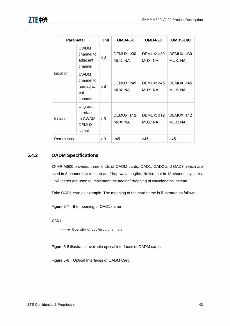
Table 5-6 Performance Parameters of OMD4-5U/OMD4-9U/OMD5-14U Cards
Parameter Unit OMD4-5U OMD4-9U OMD5-14U
CWDM
central wavelength C nm
1551
1571
1591
1611
1271
1291
1331
1351
1371
1391
1411
1431
1451
CWDM
[email protected] nm C ±6.5 C ±6.5 C ±6.5
Insertion
loss (with
connector)
Line-
CWDM dB ≤1.6 ≤1.6 ≤1.9
Line- UPG dB ≤1.6 ≤1.6 ≤1.8
ZXMP M600 V2.20 Product Description
ZTE Confidential & Proprietary 43
Parameter Unit OMD4-5U OMD4-9U OMD5-14U
Isolation
CWDM
channel to
adjacent
channel
dB DEMUX: ≥30
MUX: NA
DEMUX: ≥30
MUX: NA
DEMUX: ≥30
MUX: NA
CWDM
channel to
non-adjac
ent
channel
dB DEMUX: ≥45
MUX: NA
DEMUX: ≥45
MUX: NA
DEMUX: ≥45
MUX: NA
Isolation
Upgrade
interface
to CWDM
DEMUX
signal
dB DEMUX: ≥12
MUX: NA
DEMUX: ≥12
MUX: NA
DEMUX: ≥12
MUX: NA
Return loss dB ≥45 ≥45 ≥45
5.4.2 OADM Specifications
ZXMP M600 provides three kinds of OADM cards: OAD1, OAD2 and OAD3, which are
used in 8-channel systems to add/drop wavelengths. Notice that in 18-channel systems,
OMD cards are used to implement the adding/ dropping of wavelengths instead.
Take OAD1 card as example. The meaning of the card name is illustrated as follows:
Figure 5-7 the meaning of OAD1 name
OAD1
Quantity of add/drop channels
Figure 5-8 illustrates available optical interfaces of OADM cards.
Figure 5-8 Optical Interfaces of OADM Card

ZXMP M600 V2.20 Product Description
44 ZTE Confidential & Proprietary
OADM
ALine/I
ALine/O
BLine/O
BLine/I
B_ADiA_ADi i = 1, 2, 3
• ALine/BLine: Line optical interface in A/B direction
• A_ADi/B_ADi: Channel optical interface in A/B direction
• I/O: Input/Output
For example, “ALine/O” refers to the output line optical interface in A direction.
Table 5-7 lists the main performance parameters of ZXMP M600’s OADM.
Table 5-7 Performance Parameters of OADM
Parameter Unit CWDM Channel 1310 nm Window
CWDM bandwidth
@ 0.5 dB nm C ± 6.5 -
1310/1550 window
range nm -
1260-1360 (Transmit port)
1461-1621 (Reflect port)
Insertion
loss
(with
connector)
In-ou
t dB
≤ 1 (OAD1)
≤2 (OAD2)
≤3 (OAD3)
In-dr
op dB
≤ 1 (for 1310 nm wavelength adding/dropping on
OAD1/OAD2/OAD3)
≤ 1 (for one of the 8 CWDM wavelengths on OAD1)
≤ 2 (for one of the 8 CWDM wavelengths on OAD2)
≤ 3 (for one of the 8 CWDM wavelengths on OAD3)
Add-
out dB
≤ 1 (for 1310 nm wavelength adding/dropping on
OAD1/OAD2/OAD3)
≤ 1 (for one of the 8 CWDM wavelengths on OAD1)
≤ 2 (for one of the 8 CWDM wavelengths on OAD2)
≤ 3 (for one of the 8 CWDM wavelengths on OAD3)
ZXMP M600 V2.20 Product Description
ZTE Confidential & Proprietary 45
Parameter Unit CWDM Channel 1310 nm Window
Isolation dB DEMUX: ≥ 30
MUX: NA -
Return loss dB ≥ 45
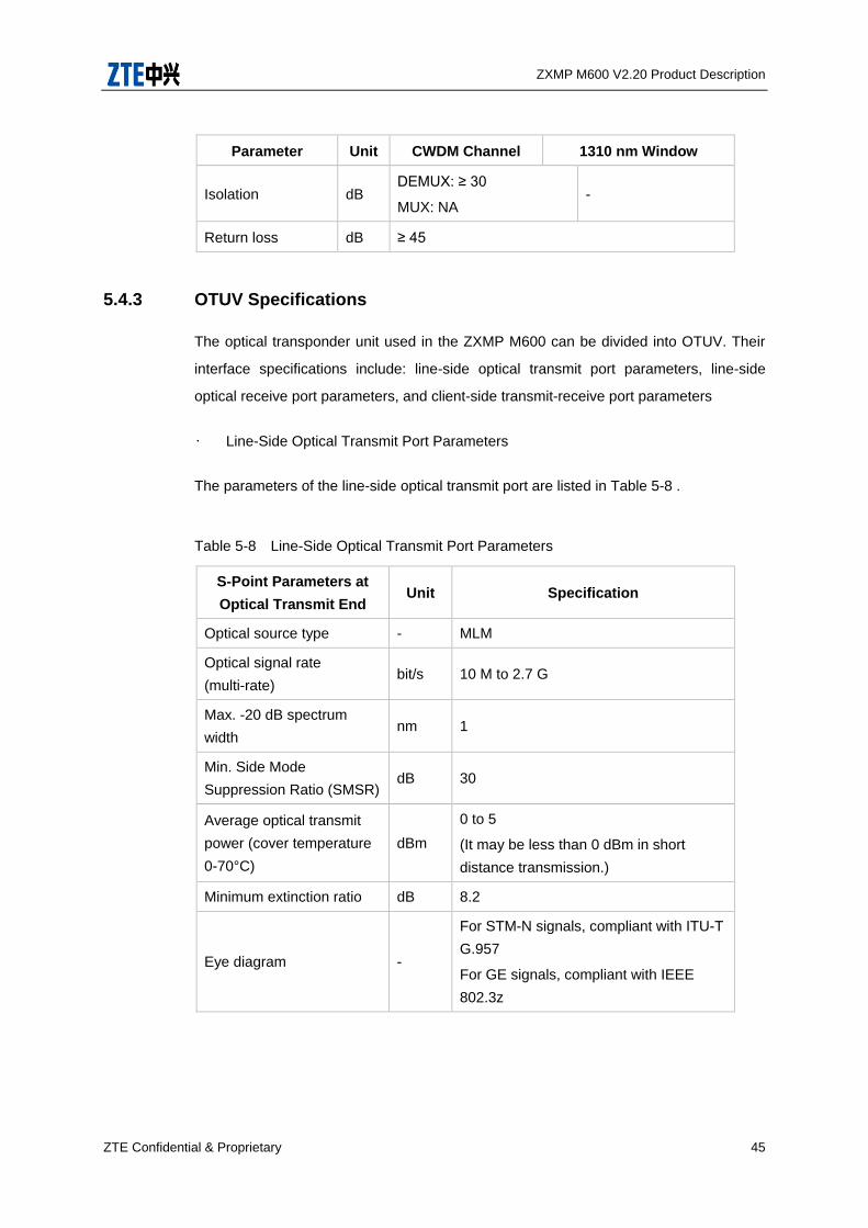
5.4.3 OTUV Specifications
The optical transponder unit used in the ZXMP M600 can be divided into OTUV. Their
interface specifications include: line-side optical transmit port parameters, line-side
optical receive port parameters, and client-side transmit-receive port parameters
• Line-Side Optical Transmit Port Parameters
The parameters of the line-side optical transmit port are listed in Table 5-8 .
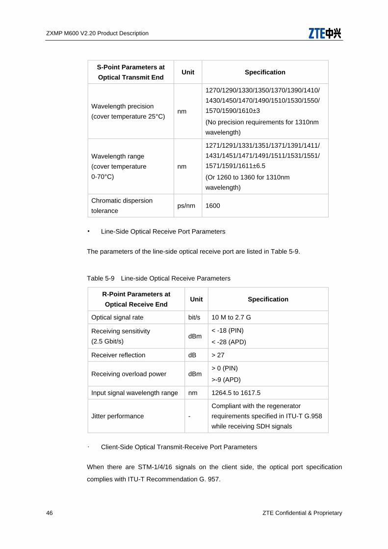
Table 5-8 Line-Side Optical Transmit Port Parameters
S-Point Parameters at
Optical Transmit End Unit Specification
Optical source type - MLM
Optical signal rate
(multi-rate) bit/s 10 M to 2.7 G
Max. -20 dB spectrum
width nm 1
Min. Side Mode
Suppression Ratio (SMSR) dB 30
Average optical transmit
power (cover temperature
0-70°C)
dBm
0 to 5
(It may be less than 0 dBm in short
distance transmission.)
Minimum extinction ratio dB 8.2
Eye diagram -
For STM-N signals, compliant with ITU-T
G.957
For GE signals, compliant with IEEE
802.3z
ZXMP M600 V2.20 Product Description
46 ZTE Confidential & Proprietary
S-Point Parameters at
Optical Transmit End Unit Specification
Wavelength precision
(cover temperature 25°C) nm
1270/1290/1330/1350/1370/1390/1410/
1430/1450/1470/1490/1510/1530/1550/
1570/1590/1610±3
(No precision requirements for 1310nm
wavelength)
Wavelength range
(cover temperature
0-70°C)
nm
1271/1291/1331/1351/1371/1391/1411/
1431/1451/1471/1491/1511/1531/1551/
1571/1591/1611±6.5
(Or 1260 to 1360 for 1310nm
wavelength)
Chromatic dispersion
tolerance ps/nm 1600
• Line-Side Optical Receive Port Parameters
The parameters of the line-side optical receive port are listed in Table 5-9.
Table 5-9 Line-side Optical Receive Parameters
R-Point Parameters at
Optical Receive End Unit Specification
Optical signal rate bit/s 10 M to 2.7 G
Receiving sensitivity
(2.5 Gbit/s) dBm
< -18 (PIN)
< -28 (APD)
Receiver reflection dB > 27
Receiving overload power dBm > 0 (PIN)
>-9 (APD)
Input signal wavelength range nm 1264.5 to 1617.5
Jitter performance -
Compliant with the regenerator
requirements specified in ITU-T G.958
while receiving SDH signals
• Client-Side Optical Transmit-Receive Port Parameters
When there are STM-1/4/16 signals on the client side, the optical port specification
complies with ITU-T Recommendation G. 957.
ZXMP M600 V2.20 Product Description
ZTE Confidential & Proprietary 47
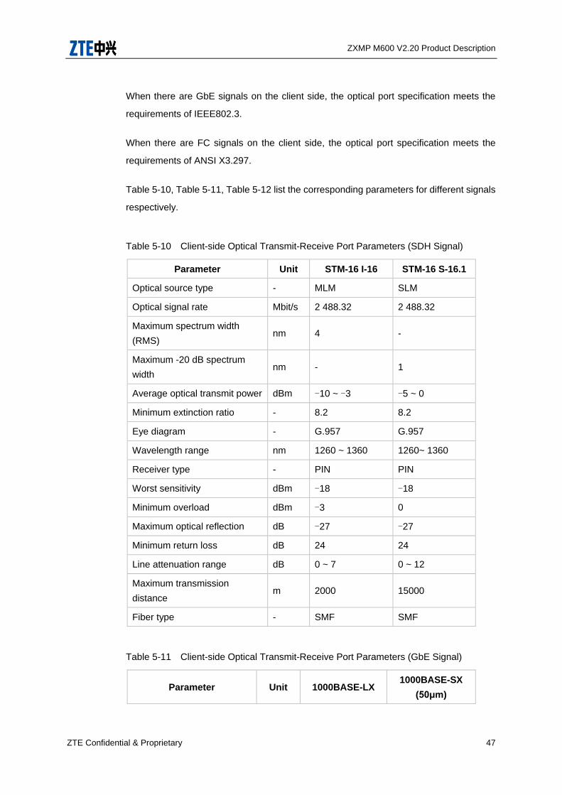
When there are GbE signals on the client side, the optical port specification meets the
requirements of IEEE802.3.
When there are FC signals on the client side, the optical port specification meets the
requirements of ANSI X3.297.
Table 5-10, Table 5-11, Table 5-12 list the corresponding parameters for different signals
respectively.
Table 5-10 Client-side Optical Transmit-Receive Port Parameters (SDH Signal)
Parameter Unit STM-16 I-16 STM-16 S-16.1
Optical source type - MLM SLM
Optical signal rate Mbit/s 2 488.32 2 488.32
Maximum spectrum width
(RMS) nm 4 -
Maximum -20 dB spectrum
width nm - 1
Average optical transmit power dBm -10 ~ -3 -5 ~ 0
Minimum extinction ratio - 8.2 8.2
Eye diagram - G.957 G.957
Wavelength range nm 1260 ~ 1360 1260~ 1360
Receiver type - PIN PIN
Worst sensitivity dBm -18 -18
Minimum overload dBm -3 0
Maximum optical reflection dB -27 -27
Minimum return loss dB 24 24
Line attenuation range dB 0 ~ 7 0 ~ 12
Maximum transmission
distance m 2000 15000
Fiber type - SMF SMF
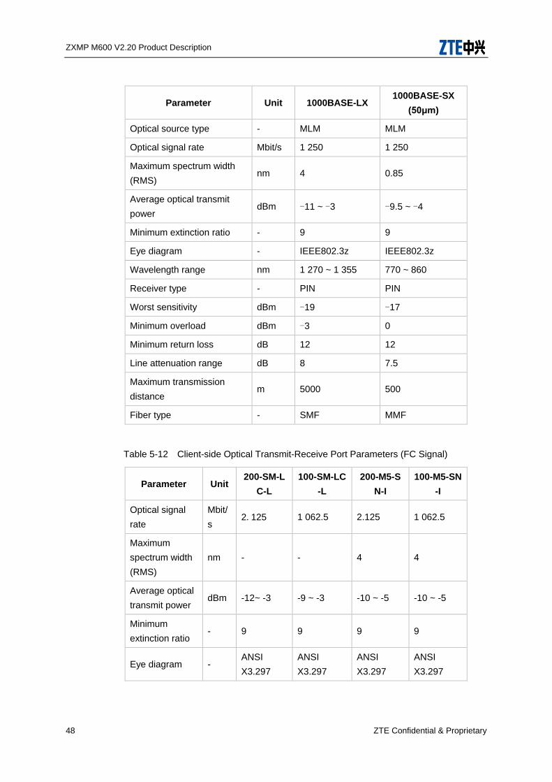
Table 5-11 Client-side Optical Transmit-Receive Port Parameters (GbE Signal)
Parameter Unit 1000BASE-LX 1000BASE-SX
(50μm)
ZXMP M600 V2.20 Product Description
48 ZTE Confidential & Proprietary
Parameter Unit 1000BASE-LX 1000BASE-SX
(50μm)
Optical source type - MLM MLM
Optical signal rate Mbit/s 1 250 1 250
Maximum spectrum width
(RMS) nm 4 0.85
Average optical transmit
power dBm -11 ~ -3 -9.5 ~ -4
Minimum extinction ratio - 9 9
Eye diagram - IEEE802.3z IEEE802.3z
Wavelength range nm 1 270 ~ 1 355 770 ~ 860
Receiver type - PIN PIN
Worst sensitivity dBm -19 -17
Minimum overload dBm -3 0
Minimum return loss dB 12 12
Line attenuation range dB 8 7.5
Maximum transmission
distance m 5000 500
Fiber type - SMF MMF
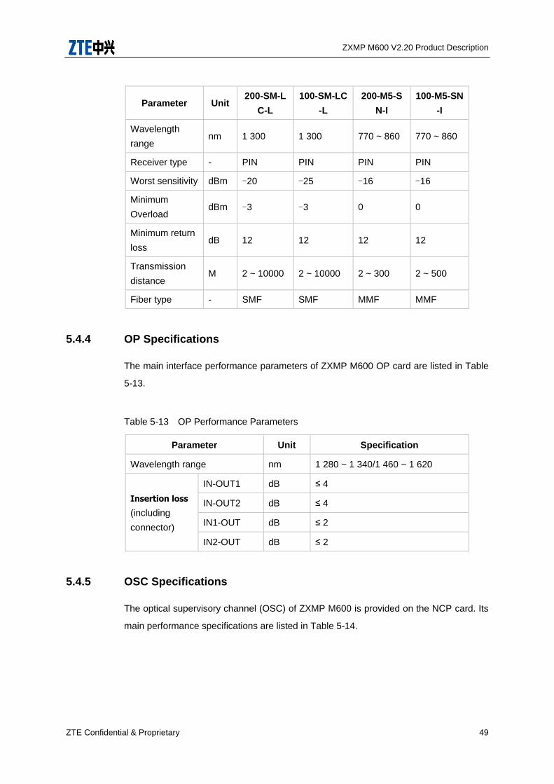
Table 5-12 Client-side Optical Transmit-Receive Port Parameters (FC Signal)
Parameter Unit 200-SM-L
C-L
100-SM-LC
-L
200-M5-S
N-I
100-M5-SN
-I
Optical signal
rate
Mbit/
s 2.125 1 062.5 2.125 1 062.5
Maximum
spectrum width
(RMS)
nm - - 4 4
Average optical
transmit power dBm -12~ -3 -9 ~ -3 -10 ~ -5 -10 ~ -5
Minimum
extinction ratio - 9 9 9 9
Eye diagram - ANSI
X3.297
ANSI
X3.297
ANSI
X3.297
ANSI
X3.297
ZXMP M600 V2.20 Product Description
ZTE Confidential & Proprietary 49
Parameter Unit 200-SM-L
C-L
100-SM-LC
-L
200-M5-S
N-I
100-M5-SN
-I
Wavelength
range nm 1 300 1 300 770 ~ 860 770 ~ 860
Receiver type - PIN PIN PIN PIN
Worst sensitivity dBm -20 -25 -16 -16
Minimum
Overload dBm -3 -3 0 0
Minimum return
loss dB 12 12 12 12
Transmission
distance M 2 ~ 10000 2 ~ 10000 2 ~ 300 2 ~ 500
Fiber type - SMF SMF MMF MMF
5.4.4 OP Specifications
The main interface performance parameters of ZXMP M600 OP card are listed in Table
5-13.
Table 5-13 OP Performance Parameters
Parameter Unit Specification
Wavelength range nm 1 280 ~ 1 340/1 460 ~ 1 620
Insertion loss
(including
connector)
IN-OUT1 dB ≤ 4
IN-OUT2 dB ≤ 4
IN1-OUT dB ≤ 2
IN2-OUT dB ≤ 2
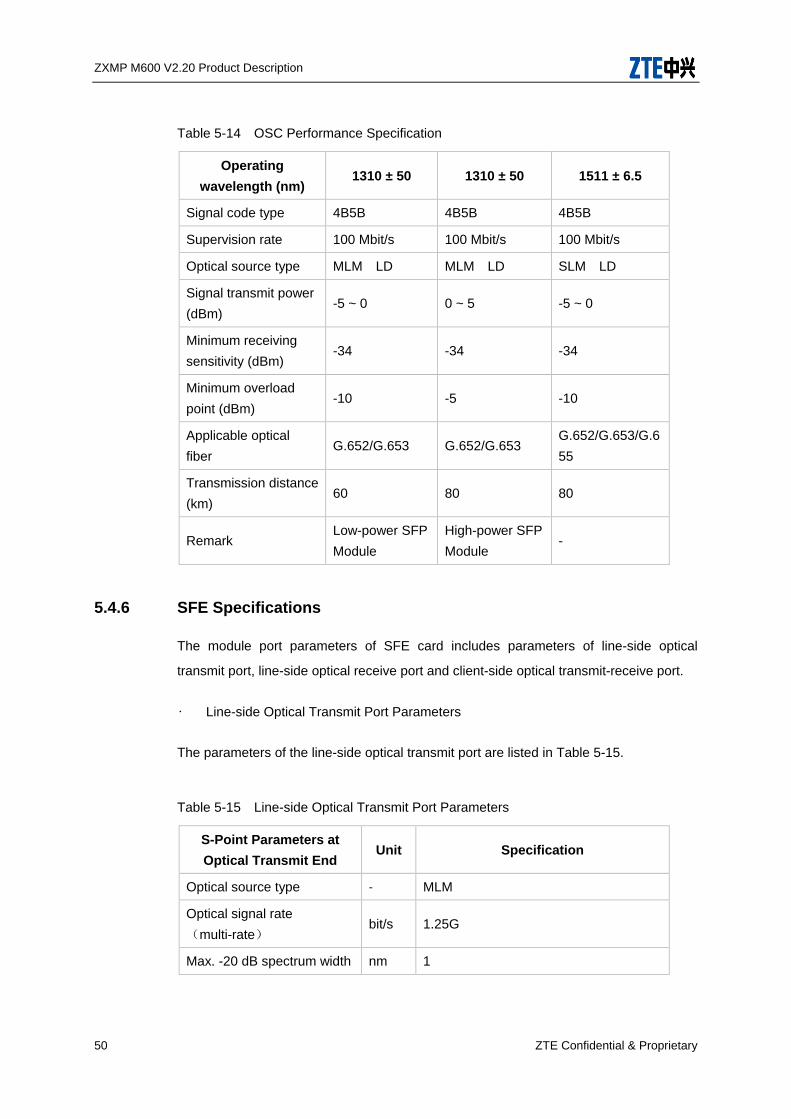
5.4.5 OSC Specifications
The optical supervisory channel (OSC) of ZXMP M600 is provided on the NCP card. Its
main performance specifications are listed in Table 5-14.
ZXMP M600 V2.20 Product Description
50 ZTE Confidential & Proprietary
Table 5-14 OSC Performance Specification
Operating
wavelength (nm) 1310 ± 50 1310 ± 50 1511 ± 6.5
Signal code type 4B5B 4B5B 4B5B
Supervision rate 100 Mbit/s 100 Mbit/s 100 Mbit/s
Optical source type MLM LD MLM LD SLM LD
Signal transmit power
(dBm) -5 ~ 0 0 ~ 5 -5 ~ 0
Minimum receiving
sensitivity (dBm) -34 -34 -34
Minimum overload
point (dBm) -10 -5 -10
Applicable optical
fiber G.652/G.653 G.652/G.653
G.652/G.653/G.6
55
Transmission distance
(km) 60 80 80
Remark Low-power SFP
Module
High-power SFP
Module -
5.4.6 SFE Specifications
The module port parameters of SFE card includes parameters of line-side optical
transmit port, line-side optical receive port and client-side optical transmit-receive port.
• Line-side Optical Transmit Port Parameters
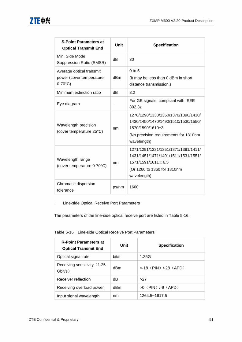
The parameters of the line-side optical transmit port are listed in Table 5-15.
Table 5-15 Line-side Optical Transmit Port Parameters
S-Point Parameters at
Optical Transmit End Unit Specification
Optical source type - MLM
Optical signal rate
(multi-rate) bit/s 1.25G
Max. -20 dB spectrum width nm 1
ZXMP M600 V2.20 Product Description
ZTE Confidential & Proprietary 51
S-Point Parameters at
Optical Transmit End Unit Specification
Min. Side Mode
Suppression Ratio (SMSR) dB 30
Average optical transmit
power (cover temperature
0-70°C)
dBm
0 to 5
(It may be less than 0 dBm in short
distance transmission.)
Minimum extinction ratio dB 8.2
Eye diagram - For GE signals, compliant with IEEE
802.3z
Wavelength precision
(cover temperature 25°C) nm
1270/1290/1330/1350/1370/1390/1410/
1430/1450/1470/1490/1510/1530/1550/
1570/1590/1610±3
(No precision requirements for 1310nm
wavelength)
Wavelength range
(cover temperature 0-70°C) nm
1271/1291/1331/1351/1371/1391/1411/
1431/1451/1471/1491/1511/1531/1551/
1571/1591/1611±6.5
(Or 1260 to 1360 for 1310nm
wavelength)
Chromatic dispersion
tolerance ps/nm 1600
• Line-side Optical Receive Port Parameters
The parameters of the line-side optical receive port are listed in Table 5-16.
Table 5-16 Line-side Optical Receive Port Parameters
R-Point Parameters at
Optical Transmit End Unit Specification
Optical signal rate bit/s 1.25G
Receiving sensitivity(1.25
Gbit/s) dBm <-18(PIN)/-28(APD)
Receiver reflection dB >27
Receiving overload power dBm >0(PIN)/-9(APD)
Input signal wavelength nm 1264.5~1617.5

ZXMP M600 V2.20 Product Description
52 ZTE Confidential & Proprietary
R-Point Parameters at
Optical Transmit End Unit Specification
range
• Client-side Optical Transmit-Receive Port Parameters
When there are GbE signals on the client side, the optical port specification meets the
requirements of IEEE802.3.They are listed in Table 5-17.
Table 5-17 Client-side Optical Transmit-Receive Port Parameters(GE Signal)
Parameter Unit 1000BASE-LX 1000BASE-SX(50μ
m)
Optical source type - MLM MLM
Optical signal rate Mbit/
s 1250 1250
Maximum spectrum
width(RMS) nm 4 0.85
Average optical
transmit power dBm -11~-3 -9.5~-3
Minimum extinction
ratio - 9 9
Eye diagram - IEEE802.3z IEEE802.3z
Wavelength range nm 1270~1355 770~860
Receiver type - PIN PIN
Worst sensitivity dBm -19 -17
Minimum overload dBm -3 0
Maximum receiver
reflection at R-Point dB -12 -12
Maximum transmission
distance m 5000 500
Fiber type - SMF MMF
ZXMP M600 V2.20 Product Description
ZTE Confidential & Proprietary 53
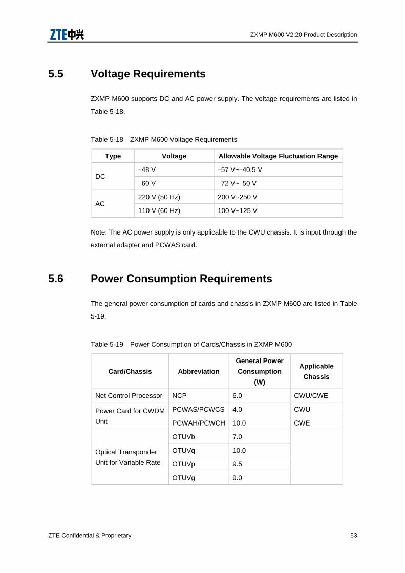
5.5 Voltage Requirements
ZXMP M600 supports DC and AC power supply. The voltage requirements are listed in
Table 5-18.
Table 5-18 ZXMP M600 Voltage Requirements
Type Voltage Allowable Voltage Fluctuation Range
DC -48 V -57 V~-40.5 V
-60 V -72 V~-50 V
AC 220 V (50 Hz) 200 V~250 V
110 V (60 Hz) 100 V~125 V
Note: The AC power supply is only applicable to the CWU chassis. It is input through the
external adapter and PCWAS card.
5.6 Power Consumption Requirements
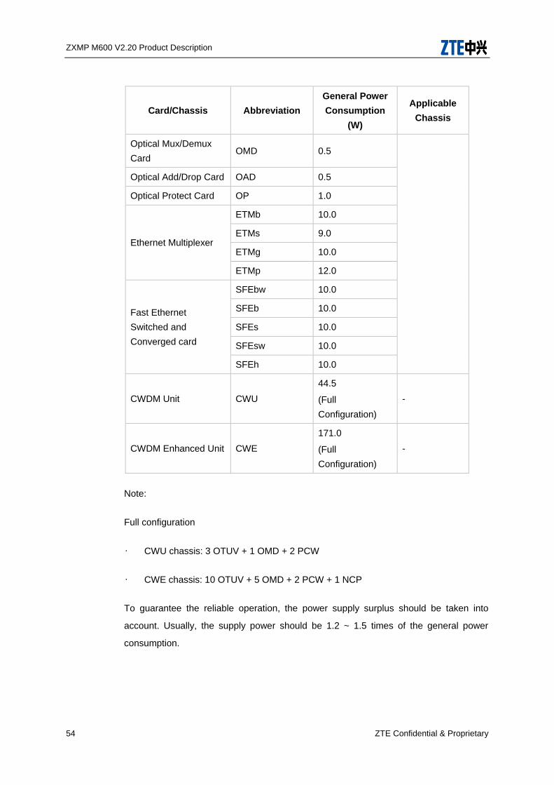
The general power consumption of cards and chassis in ZXMP M600 are listed in Table
5-19.
Table 5-19 Power Consumption of Cards/Chassis in ZXMP M600
Card/Chassis Abbreviation
General Power
Consumption
(W)
Applicable
Chassis
Net Control Processor NCP 6.0 CWU/CWE
Power Card for CWDM
Unit
PCWAS/PCWCS 4.0 CWU
PCWAH/PCWCH 10.0 CWE
Optical Transponder
Unit for Variable Rate
OTUVb 7.0
OTUVq 10.0
OTUVp 9.5
OTUVg 9.0
ZXMP M600 V2.20 Product Description
54 ZTE Confidential & Proprietary
Card/Chassis Abbreviation
General Power
Consumption
(W)
Applicable
Chassis
Optical Mux/Demux
Card OMD 0.5
Optical Add/Drop Card OAD 0.5
Optical Protect Card OP 1.0
Ethernet Multiplexer
ETMb 10.0
ETMs 9.0
ETMg 10.0
ETMp 12.0
Fast Ethernet
Switched and
Converged card
SFEbw 10.0
SFEb 10.0
SFEs 10.0
SFEsw 10.0
SFEh 10.0
CWDM Unit CWU
44.5
(Full
Configuration)
-
CWDM Enhanced Unit CWE
171.0
(Full
Configuration)
-
Note:
Full configuration
• CWU chassis: 3 OTUV + 1 OMD + 2 PCW
• CWE chassis: 10 OTUV + 5 OMD + 2 PCW + 1 NCP
To guarantee the reliable operation, the power supply surplus should be taken into
account. Usually, the supply power should be 1.2 ~ 1.5 times of the general power
consumption.
ZXMP M600 V2.20 Product Description
ZTE Confidential & Proprietary 55
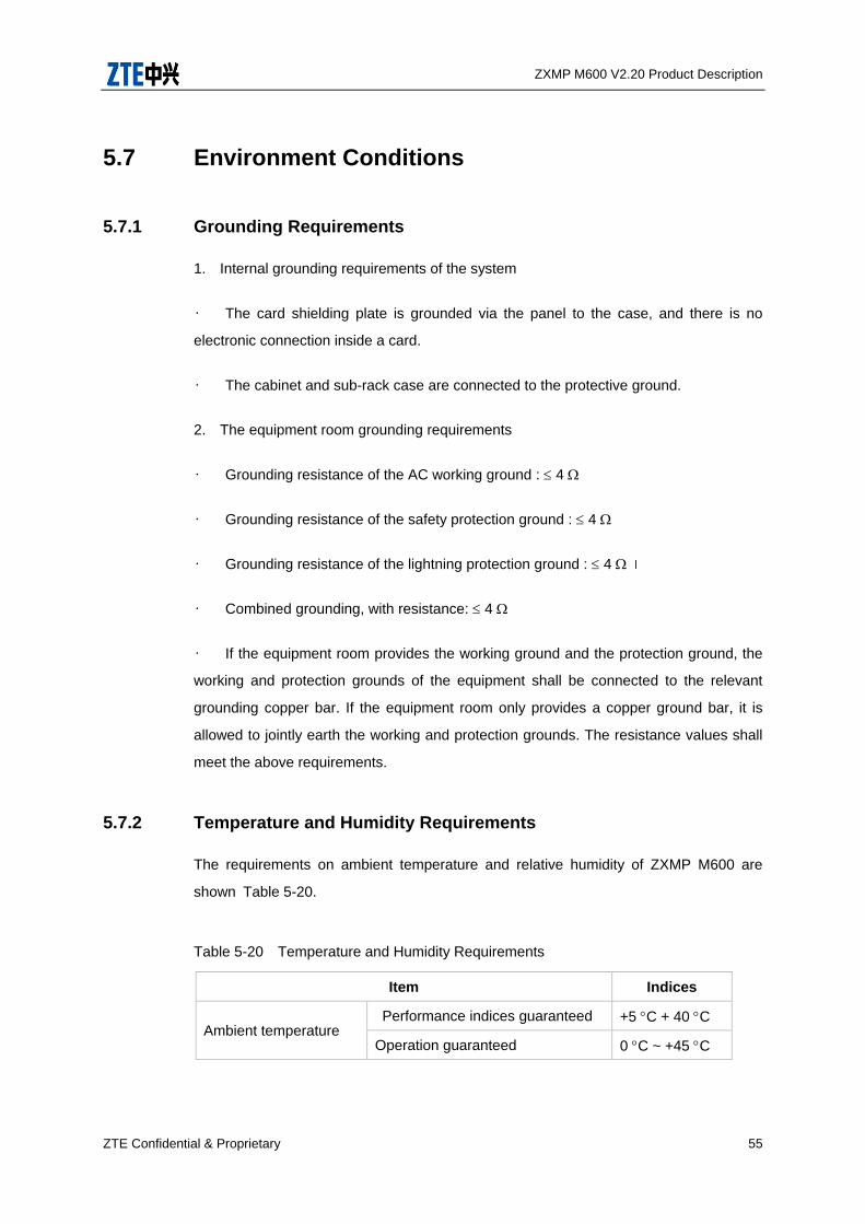
5.7 Environment Conditions
5.7.1 Grounding Requirements
1. Internal grounding requirements of the system
• The card shielding plate is grounded via the panel to the case, and there is no
electronic connection inside a card.
• The cabinet and sub-rack case are connected to the protective ground.
2. The equipment room grounding requirements
• Grounding resistance of the AC working ground : 4
• Grounding resistance of the safety protection ground : 4
• Grounding resistance of the lightning protection ground : 4
• Combined grounding, with resistance: 4
• If the equipment room provides the working ground and the protection ground, the
working and protection grounds of the equipment shall be connected to the relevant
grounding copper bar. If the equipment room only provides a copper ground bar, it is
allowed to jointly earth the working and protection grounds. The resistance values shall
meet the above requirements.
5.7.2 Temperature and Humidity Requirements
The requirements on ambient temperature and relative humidity of ZXMP M600 are
shown Table 5-20.
Table 5-20 Temperature and Humidity Requirements
Item Indices
Ambient temperature Performance indices guaranteed +5 C + 40 C
Operation guaranteed 0 C ~ +45 C
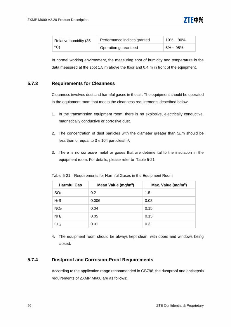
ZXMP M600 V2.20 Product Description
56 ZTE Confidential & Proprietary
Relative humidity (35
C)
Performance indices granted 10% ~ 90%
Operation guaranteed 5% ~ 95%
In normal working environment, the measuring spot of humidity and temperature is the
data measured at the spot 1.5 m above the floor and 0.4 m in front of the equipment.
5.7.3 Requirements for Cleanness
Cleanness involves dust and harmful gases in the air. The equipment should be operated
in the equipment room that meets the cleanness requirements described below:
1. In the transmission equipment room, there is no explosive, electrically conductive,
magnetically conductive or corrosive dust.
2. The concentration of dust particles with the diameter greater than 5µm should be
less than or equal to 3 104 particles/m3.
3. There is no corrosive metal or gases that are detrimental to the insulation in the
equipment room. For details, please refer to Table 5-21.
Table 5-21 Requirements for Harmful Gases in the Equipment Room
Harmful Gas Mean Value (mg/m3) Max. Value (mg/m3)
SO2 0.2 1.5
H2S 0.006 0.03
NO2 0.04 0.15
NH3 0.05 0.15
CL2 0.01 0.3
4. The equipment room should be always kept clean, with doors and windows being
closed.
5.7.4 Dustproof and Corrosion-Proof Requirements
According to the application range recommended in GB798, the dustproof and antisepsis
requirements of ZXMP M600 are as follows:

ZXMP M600 V2.20 Product Description
ZTE Confidential & Proprietary 57
1. Storage environment conditions: For 1K5/1Z1/1B2/1C2/1S3/1M3, the storage
duration is 180 days.
2. Transportation environment conditions: For 2K4P/2B2/2C2/2S3/2M3, the
transportation duration is 30 days.
3. Application environment conditions: For 3K5/3Z2/3Z7/3B2/3C2/3S2/3M3, the
continuous operation time is 20 years.
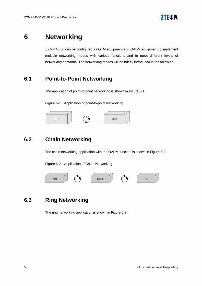
ZXMP M600 V2.20 Product Description
58 ZTE Confidential & Proprietary
6 Networking
ZXMP M600 can be configured as OTM equipment and OADM equipment to implement
multiple networking modes with various functions and to meet different levels of
networking demands. The networking modes will be briefly introduced in the following.
6.1 Point-to-Point Networking
The application of point-to-point networking is shown in Figure 6-1.
Figure 6-1 Application of point-to-point Networking
6.2 Chain Networking
The chain networking application with the OADM function is shown in Figure 6-2.
Figure 6-2 Application of Chain Networking
OTM OADM OTM
6.3 Ring Networking
The ring networking application is shown in Figure 6-3.
OTM OTM
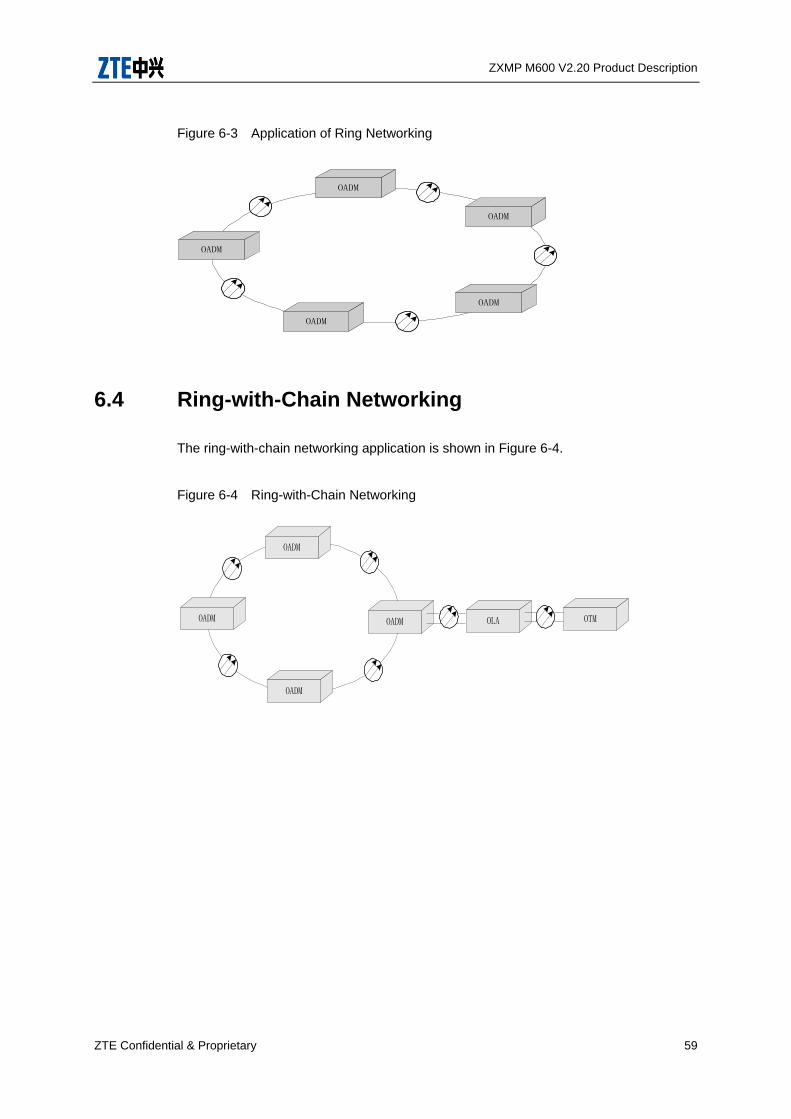
ZXMP M600 V2.20 Product Description
ZTE Confidential & Proprietary 59
Figure 6-3 Application of Ring Networking
OADM
OADM
OADM
OADM
OADM
6.4 Ring-with-Chain Networking
The ring-with-chain networking application is shown in Figure 6-4.
Figure 6-4 Ring-with-Chain Networking
OADM
OADM
OADM
OLAOADM OTM

ZXMP M600 V2.20 Product Description
60 ZTE Confidential & Proprietary
7 Configuration Instructions
7.1 System Configuration
ZXMP M600 can be configured as either OTM equipment or OADM equipment.
7.1.1 OTM
The OTM can add/drop all services and implement functions of a line terminal node.
When the ZXMP M600 is configured as OTM equipment, the relation among the
platforms is shown in Figure 7-1.
Figure 7-1 Functional Structure of OTM Equipment
Multiplexing/demultiplexing platform
Service signal
Service signal
Optical lineService
convergenceplatform
Optical transferplatform
Monitor platform
Mu
ltiplex
ing
Dem
ultip
lexin
g
7.1.2 OADM
The OADM equipment can add/drop services with specified wavelengths and directly
connect other services. When the ZXMP M600 is configured as OADM equipment, the
relation among the platforms is shown in Figure 7-2.
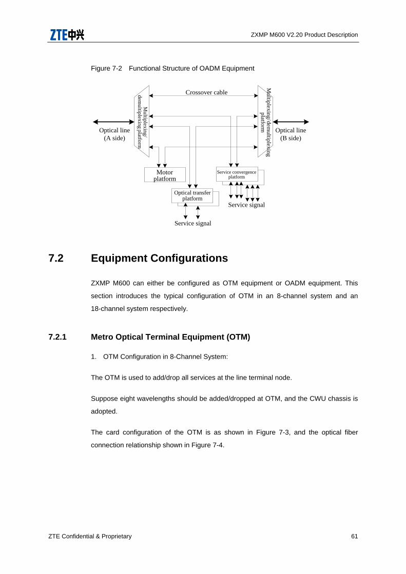
ZXMP M600 V2.20 Product Description
ZTE Confidential & Proprietary 61
Figure 7-2 Functional Structure of OADM Equipment
Mu
ltiplex
ing
/ dem
ultip
lexin
gp
latform
Crossover cable
Optical line
(A side)
Optical line
(B side)
Motorplatform
Optical transferplatform
Service convergenceplatform
Service signal
Service signal
Mu
ltiplex
ing
/d
emu
ltiplex
ing
platfo
rm
7.2 Equipment Configurations
ZXMP M600 can either be configured as OTM equipment or OADM equipment. This
section introduces the typical configuration of OTM in an 8-channel system and an
18-channel system respectively.
7.2.1 Metro Optical Terminal Equipment (OTM)
1. OTM Configuration in 8-Channel System:
The OTM is used to add/drop all services at the line terminal node.
Suppose eight wavelengths should be added/dropped at OTM, and the CWU chassis is
adopted.
The card configuration of the OTM is as shown in Figure 7-3, and the optical fiber
connection relationship shown in Figure 7-4.
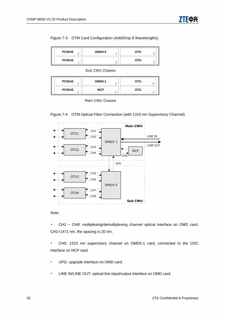
ZXMP M600 V2.20 Product Description
62 ZTE Confidential & Proprietary
Figure 7-3 OTM Card Configuration (Add/Drop 8 Wavelengths)
PCWAS
PCWAS
OMD5-1
NCP
OTU
OTU
PCWAS
PCWAS
OMD4-5 OTU
OTU
Main CWU Chassis
Sub CWU Chassis
1
2
3
4 6
5
1
2
3
4 6
5
Figure 7-4 OTM Optical Fiber Connection (with 1310 nm Supervisory Channel)
Note:
• CH1 ~ CH8: multiplexing/demultiplexing channel optical interface on OMD card,
CH1=1471 nm, the spacing is 20 nm.
• CH0: 1310 nm supervisory channel on OMD5-1 card, connected to the OSC
interface on NCP card.
• UPG: upgrade interface on OMD card.
• LINE IN/LINE OUT: optical line input/output interface on OMD card.
OTU1
OTU2
OTU3
OTU4
OMD5-1
OMD4-5
NCP
Main CWU
Sub CWU
UPG
CH0
LINE IN
LINE OUT
CH1
CH2
CH3
CH4
CH5
CH6
CH7
CH8

ZXMP M600 V2.20 Product Description
ZTE Confidential & Proprietary 63
The following explains the configuration of OTM as shown in Figure 7-3.
• PCWAS cards are used to provide –48 V DC power supply to the system.
• OTUV cards used in this OTM node are dual-path/bidirectional OTUV cards.
OTUV cards of other types can be used according to actual requirements.
• The OMD5-1 card configured in the master CWU chassis provides the 1310 nm
channel interface. In this configuration, the 1310 nm channel is used as the supervisory
channel.
• If the OMS 1+1 protection function is needed, determine the position of OP
card and corresponding optical connection according to the protection type.
If the service convergence function is needed, replace one OTUV card as shown in
Figure 7-3 with a ETM card.
2. OTM Configuration in 18-Channel System
Suppose an OTM equipment adds/drops 18 wavelengths and a CWE chassis is used.
The card configuration of the OTM equipment in the 18-channel system is shown in
Figure 7-5.
Figure 7-5 Card Configuration in OTM Equipment (CWE Chassis, Adding/Dropping 18
Wavelengths)
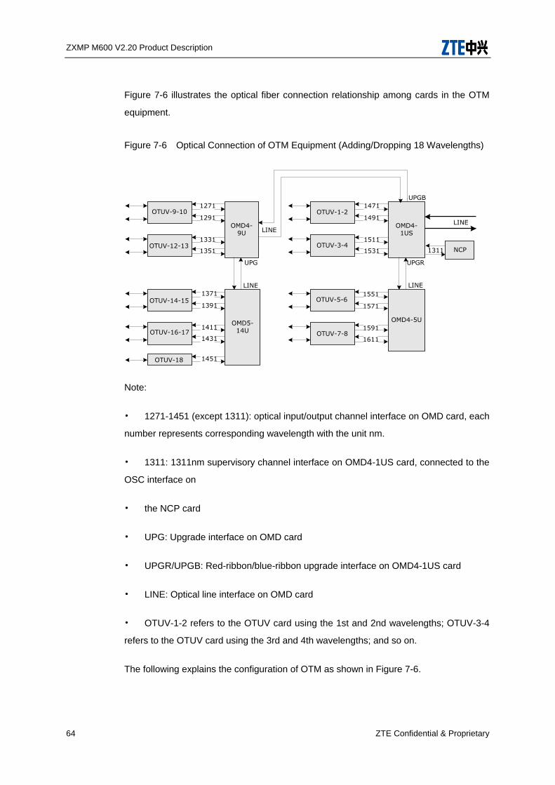
ZXMP M600 V2.20 Product Description
64 ZTE Confidential & Proprietary
Figure 7-6 illustrates the optical fiber connection relationship among cards in the OTM
equipment.
Figure 7-6 Optical Connection of OTM Equipment (Adding/Dropping 18 Wavelengths)
NCP1311
1271
1291
1331
1351
OMD4-9U
1371
1391
1411
1431
OMD5-14U
OTUV-18 1451
OTUV-1-2
OTUV-3-4
1471
1491
1511
1531
OMD4-1US
1551
1571
1591
1611
OMD4-5U
LINE
UPG
LINE
OTUV-5-6
OTUV-7-8
OTUV-9-10
OTUV-12-13
OTUV-14-15
OTUV-16-17
UPGB
UPGR
LINE
LINE
Note:
• 1271-1451 (except 1311): optical input/output channel interface on OMD card, each
number represents corresponding wavelength with the unit nm.
• 1311: 1311nm supervisory channel interface on OMD4-1US card, connected to the
OSC interface on
• the NCP card
• UPG: Upgrade interface on OMD card
• UPGR/UPGB: Red-ribbon/blue-ribbon upgrade interface on OMD4-1US card
• LINE: Optical line interface on OMD card
• OTUV-1-2 refers to the OTUV card using the 1st and 2nd wavelengths; OTUV-3-4
refers to the OTUV card using the 3rd and 4th wavelengths; and so on.
The following explains the configuration of OTM as shown in Figure 7-6.
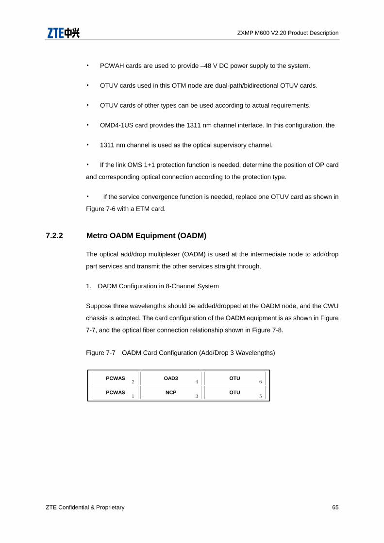
ZXMP M600 V2.20 Product Description
ZTE Confidential & Proprietary 65
• PCWAH cards are used to provide –48 V DC power supply to the system.
• OTUV cards used in this OTM node are dual-path/bidirectional OTUV cards.
• OTUV cards of other types can be used according to actual requirements.
• OMD4-1US card provides the 1311 nm channel interface. In this configuration, the
• 1311 nm channel is used as the optical supervisory channel.
• If the link OMS 1+1 protection function is needed, determine the position of OP card
and corresponding optical connection according to the protection type.
• If the service convergence function is needed, replace one OTUV card as shown in
Figure 7-6 with a ETM card.
7.2.2 Metro OADM Equipment (OADM)
The optical add/drop multiplexer (OADM) is used at the intermediate node to add/drop
part services and transmit the other services straight through.
1. OADM Configuration in 8-Channel System
Suppose three wavelengths should be added/dropped at the OADM node, and the CWU
chassis is adopted. The card configuration of the OADM equipment is as shown in Figure
7-7, and the optical fiber connection relationship shown in Figure 7-8.
Figure 7-7 OADM Card Configuration (Add/Drop 3 Wavelengths)
PCWAS
PCWAS
OAD3
NCP
OTU
OTU1
2
3
4 6
5

ZXMP M600 V2.20 Product Description
66 ZTE Confidential & Proprietary
Figure 7-8 OADM Optical Fiber Connection (Add/Drop 3 Wavelengths)
B_AD2
OAD3
OTUV1 OTUV2
NCP
ALine BLine
A_AD1 A_AD3A_AD2 B_AD3 B_AD1
AOSC BOSC
Note:
ALine: Line optical interface in A direction
BLine: Line optical interface in B direction
A_ADn: Channel optical interface n in A direction, n=1, 2, 3
B_BDn: Channel optical interface n in B direction, n=1, 2, 3
AOSC: Optical supervisory interface in A direction
BOSC: Optical supervisory interface in B direction
The following explains the configuration of OADM as shown in Figure 7-7.
• Two PCWAS cards are used to provide –48 V DC power supply to the system, as
shown in Figure 7-7.
• This configuration is applicable to the case of adding/dropping three wavelengths.
As shown in Figure 7-8, A_AD1 and B_AD1 are supervisory channels, which are
connected to AOSC and BOSC interfaces on the NCP card respectively. The supervisory
channel wavelength can be 1310 nm or 1510 nm.
• If it is unnecessary to use the 1310 nm supervisory channel as an add/drop
wavelength, the channel occupied by the NCP card in the OADM equipment as shown in
Figure 7-7 can be replaced by a service add/drop channel.
• Use proper OAD card according to the number of wavelengths to be added/dropped.
Use OAD1 card to add/drop one wavelength, OAD2 card to add/drop two wavelengths
and OAD3 card to add/drop three wavelengths.
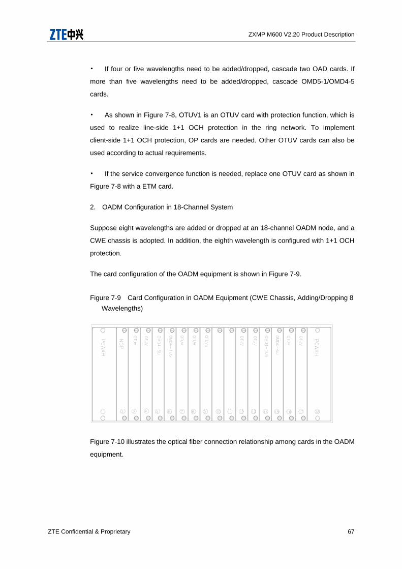
ZXMP M600 V2.20 Product Description
ZTE Confidential & Proprietary 67
• If four or five wavelengths need to be added/dropped, cascade two OAD cards. If
more than five wavelengths need to be added/dropped, cascade OMD5-1/OMD4-5
cards.
• As shown in Figure 7-8, OTUV1 is an OTUV card with protection function, which is
used to realize line-side 1+1 OCH protection in the ring network. To implement
client-side 1+1 OCH protection, OP cards are needed. Other OTUV cards can also be
used according to actual requirements.
• If the service convergence function is needed, replace one OTUV card as shown in
Figure 7-8 with a ETM card.
2. OADM Configuration in 18-Channel System
Suppose eight wavelengths are added or dropped at an 18-channel OADM node, and a
CWE chassis is adopted. In addition, the eighth wavelength is configured with 1+1 OCH
protection.
The card configuration of the OADM equipment is shown in Figure 7-9.
Figure 7-9 Card Configuration in OADM Equipment (CWE Chassis, Adding/Dropping 8
Wavelengths)
Figure 7-10 illustrates the optical fiber connection relationship among cards in the OADM
equipment.
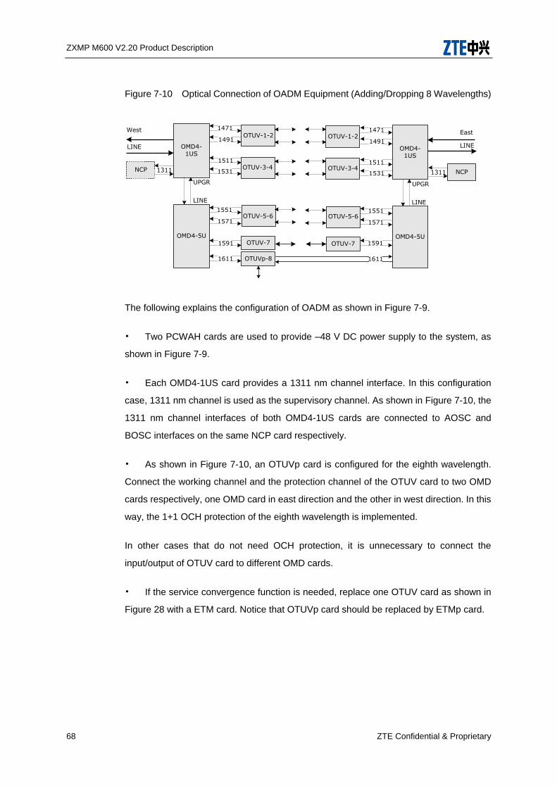
ZXMP M600 V2.20 Product Description
68 ZTE Confidential & Proprietary
Figure 7-10 Optical Connection of OADM Equipment (Adding/Dropping 8 Wavelengths)
NCP1311
1471
1491
1511
1531
OMD4-1US
1551
1571
OMD4-5U
LINE
LINE
UPGR
OTUV-1-2
OTUV-3-4
1471
1491
1511
1531
OMD4-1US
OTUV-7
1551
1571
1591
1611
OMD4-5U
LINE
OTUV-5-6
UPGR
OTUV-1-2
OTUV-3-4
OTUV-5-6
LINE
OTUVp-8
OTUV-7 1591
1611
West East
NCP 1311
The following explains the configuration of OADM as shown in Figure 7-9.
• Two PCWAH cards are used to provide –48 V DC power supply to the system, as
shown in Figure 7-9.
• Each OMD4-1US card provides a 1311 nm channel interface. In this configuration
case, 1311 nm channel is used as the supervisory channel. As shown in Figure 7-10, the
1311 nm channel interfaces of both OMD4-1US cards are connected to AOSC and
BOSC interfaces on the same NCP card respectively.
• As shown in Figure 7-10, an OTUVp card is configured for the eighth wavelength.
Connect the working channel and the protection channel of the OTUV card to two OMD
cards respectively, one OMD card in east direction and the other in west direction. In this
way, the 1+1 OCH protection of the eighth wavelength is implemented.
In other cases that do not need OCH protection, it is unnecessary to connect the
input/output of OTUV card to different OMD cards.
• If the service convergence function is needed, replace one OTUV card as shown in
Figure 28 with a ETM card. Notice that OTUVp card should be replaced by ETMp card.
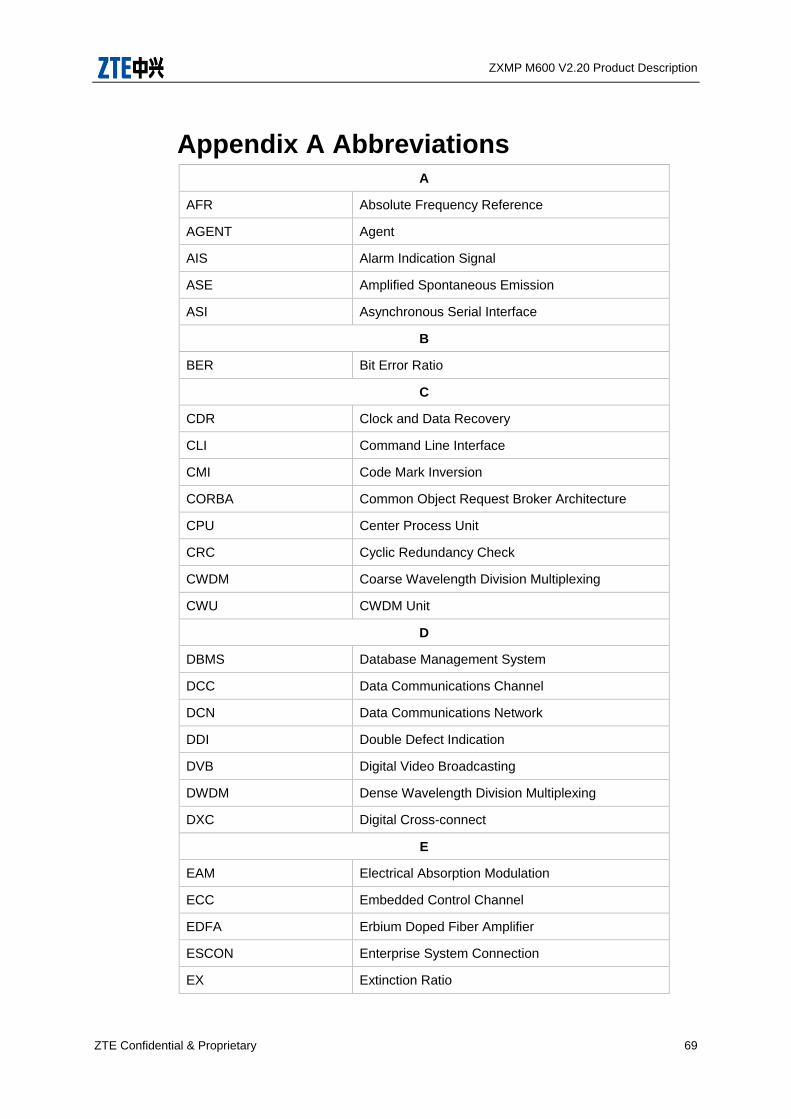
ZXMP M600 V2.20 Product Description
ZTE Confidential & Proprietary 69
Appendix A Abbreviations A
AFR Absolute Frequency Reference
AGENT Agent
AIS Alarm Indication Signal
ASE Amplified Spontaneous Emission
ASI Asynchronous Serial Interface
B
BER Bit Error Ratio
C
CDR Clock and Data Recovery
CLI Command Line Interface
CMI Code Mark Inversion
CORBA Common Object Request Broker Architecture
CPU Center Process Unit
CRC Cyclic Redundancy Check
CWDM Coarse Wavelength Division Multiplexing
CWU CWDM Unit
D
DBMS Database Management System
DCC Data Communications Channel
DCN Data Communications Network
DDI Double Defect Indication
DVB Digital Video Broadcasting
DWDM Dense Wavelength Division Multiplexing
DXC Digital Cross-connect
E
EAM Electrical Absorption Modulation
ECC Embedded Control Channel
EDFA Erbium Doped Fiber Amplifier
ESCON Enterprise System Connection
EX Extinction Ratio

ZXMP M600 V2.20 Product Description
70 ZTE Confidential & Proprietary
F
FC Fiber Channel
FDI Forward Defection Indication
FEC Forward Error Correction
FICON Fiber Connection
FPDC Fiber Passive Dispersion Compensator
G
GbE Gigabits Ethernet
GEM Gigabit Ethernet Multiplexing
GUI Graphical User Interfaces
I
IP Internet Protocol
L
LD Laser Diode
LOF Loss of Frame
LOS Loss of Signal
M
MANAGER
MCU Management and Control Unit
MMF Multi Mode Fiber
MQW Multiple Quantum Well
MSP Multiplex Section Protection
MST Multiplex Section Termination
MSTP Multi-Service Transport Platform
MTBF Mean Time Between Failure
N
NCP Net Control Processor
NE Network Element
NNI Network Node Interface
NMCC Network Manage Control Center
NRZ Non Return to Zero
NT Network Termination
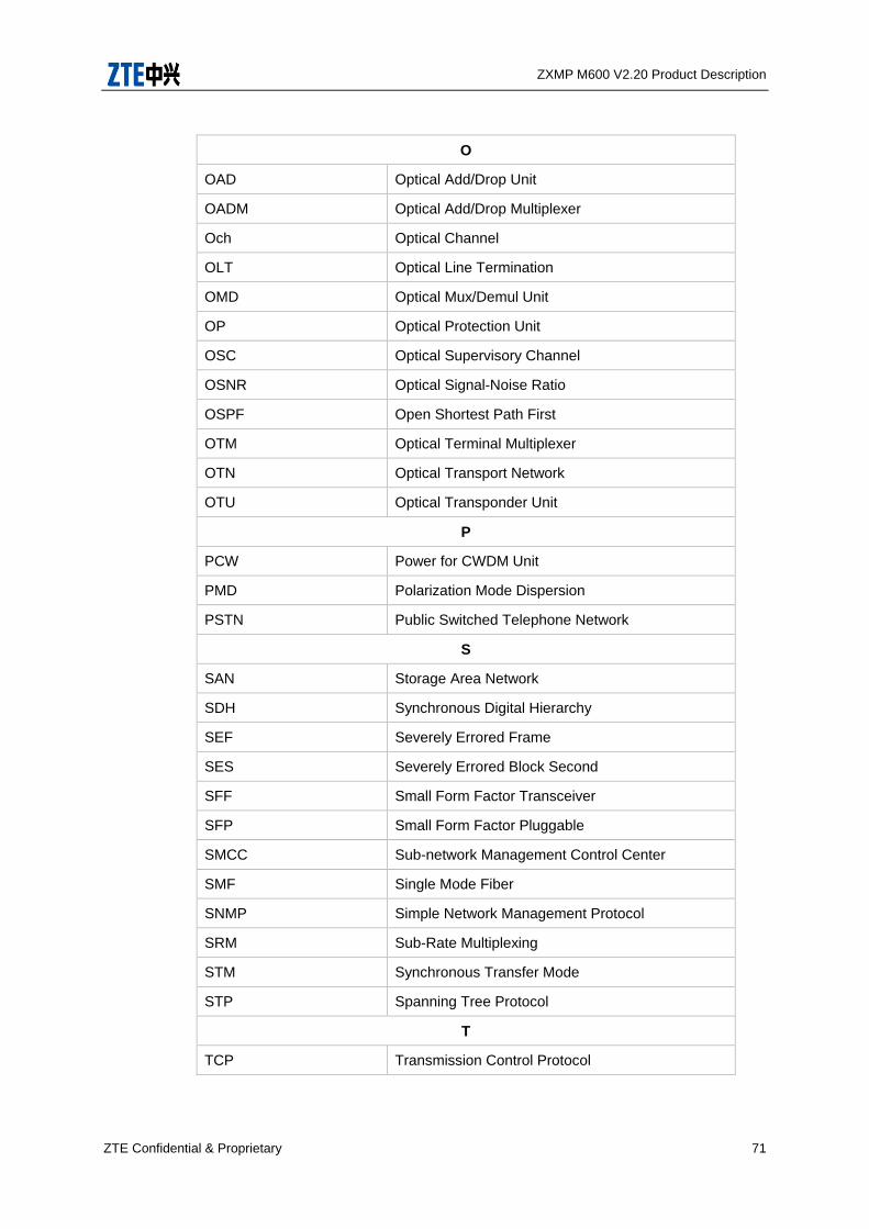
ZXMP M600 V2.20 Product Description
ZTE Confidential & Proprietary 71
O
OAD Optical Add/Drop Unit
OADM Optical Add/Drop Multiplexer
Och Optical Channel
OLT Optical Line Termination
OMD Optical Mux/Demul Unit
OP Optical Protection Unit
OSC Optical Supervisory Channel
OSNR Optical Signal-Noise Ratio
OSPF Open Shortest Path First
OTM Optical Terminal Multiplexer
OTN Optical Transport Network
OTU Optical Transponder Unit
P
PCW Power for CWDM Unit
PMD Polarization Mode Dispersion
PSTN Public Switched Telephone Network
S
SAN Storage Area Network
SDH Synchronous Digital Hierarchy
SEF Severely Errored Frame
SES Severely Errored Block Second
SFF Small Form Factor Transceiver
SFP Small Form Factor Pluggable
SMCC Sub-network Management Control Center
SMF Single Mode Fiber
SNMP Simple Network Management Protocol
SRM Sub-Rate Multiplexing
STM Synchronous Transfer Mode
STP Spanning Tree Protocol
T
TCP Transmission Control Protocol
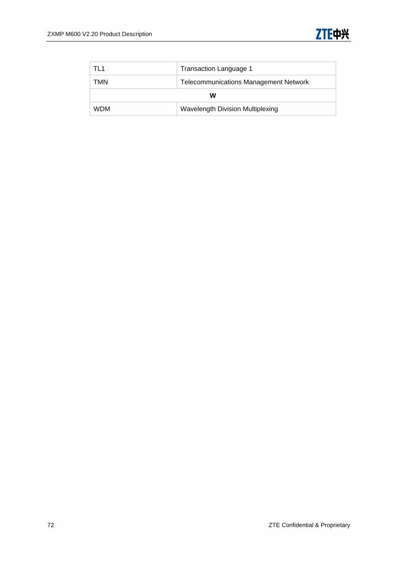
ZXMP M600 V2.20 Product Description
72 ZTE Confidential & Proprietary
TL1 Transaction Language 1
TMN Telecommunications Management Network
W
WDM Wavelength Division Multiplexing

ZXMP M600 V2.20 Product Description
ZTE Confidential & Proprietary 73
Appendix B Followed Standards and
Recommendations
ZXMP M600 complies with the following recommendations and standards follow the
table.
Recommendation
/
Standard
Description
ITU-T
G.652-2003-3 Characteristics of a Single-Mode Optical Fibre Cable
ITU-T
G.653-2003-12
Characteristics of a Dispersion-Shifted Single-Mode
Optical Fibre Cable
ITU-T
G.655-2003-3
Characteristics of a non-zero Dispersion Single-Mode
Optical Fibre Cable
ITU-T
G.694.2-2003-12
Spectral Grids for WDM Applications: CWDM Wavelength
Grid
ITU-T
G.695-2004-2
Optical interfaces for Coarse Wavelength Division
Multiplexing applications
ITU-T
G .703-2001-11
Physical/Electrical Characteristics of Hierarchical Digital
Interfaces
ITU-T
G.783-2000-10
Characteristics of Synchronous Digital Hierarchy (SDH)
Equipment Functional Blocks
ITU-T
G.798-2002-06
Characteristics of Optical Transport Network Equipment
Functional Blocks
ITU-TG.825-2002-
06
The control of jitter and wander within digital networks
which are based on the Synchronous Digital Hierarchy
(SDH)
ITU-T G.959.1 Optical Transport Network Physical Layer Interfaces
ITU-T G.871 Framework for Optical Transport Network
Recommendations
ITU-T G.872 Architecture of Optical Transport Networks
ITU-T G.873 Optical Transport Networks Requirements
ITU-T G.874 Management Aspects of Optical Transport Network
Element
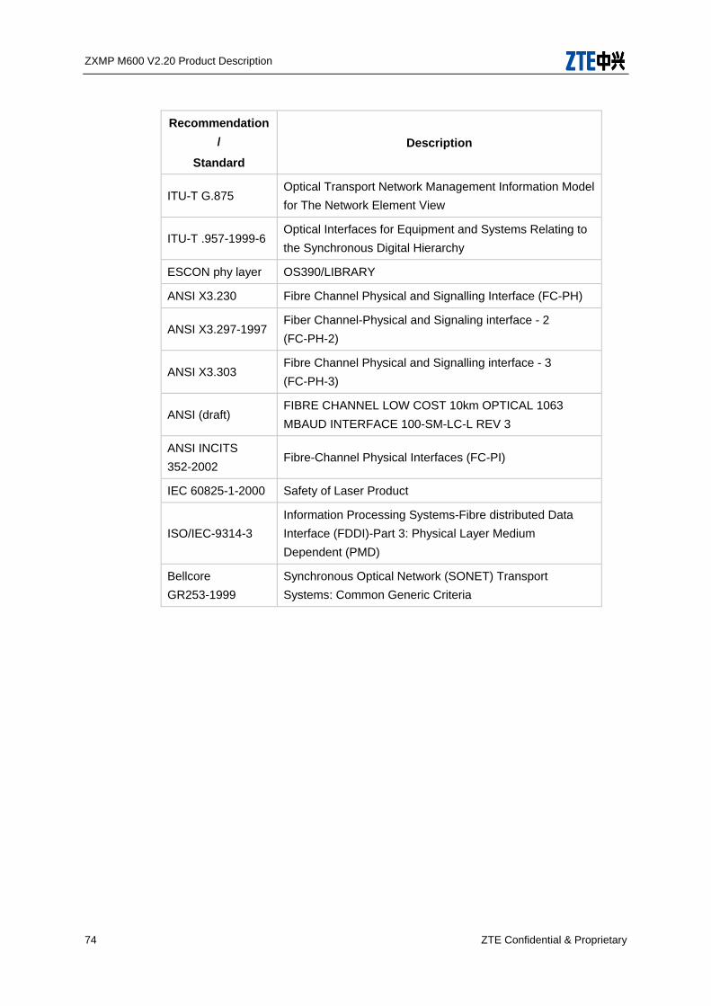
ZXMP M600 V2.20 Product Description
74 ZTE Confidential & Proprietary
Recommendation
/
Standard
Description
ITU-T G.875 Optical Transport Network Management Information Model
for The Network Element View
ITU-T .957-1999-6 Optical Interfaces for Equipment and Systems Relating to
the Synchronous Digital Hierarchy
ESCON phy layer OS390/LIBRARY
ANSI X3.230 Fibre Channel Physical and Signalling Interface (FC-PH)
ANSI X3.297-1997 Fiber Channel-Physical and Signaling interface - 2
(FC-PH-2)
ANSI X3.303 Fibre Channel Physical and Signalling interface - 3
(FC-PH-3)
ANSI (draft) FIBRE CHANNEL LOW COST 10km OPTICAL 1063
MBAUD INTERFACE 100-SM-LC-L REV 3
ANSI INCITS
352-2002 Fibre-Channel Physical Interfaces (FC-PI)
IEC 60825-1-2000 Safety of Laser Product
ISO/IEC-9314-3
Information Processing Systems-Fibre distributed Data
Interface (FDDI)-Part 3: Physical Layer Medium
Dependent (PMD)
Bellcore
GR253-1999
Synchronous Optical Network (SONET) Transport
Systems: Common Generic Criteria