design of the-step-feed activated sludge processdigitool.library.mcgill.ca/thesisfile64054.pdf ·...
TRANSCRIPT

c
0/ • "
"1
c
o
r. .. DESIGN OF THE-STEP-FEED
ACTIVATED SLUDGE PROCESS
by
OSWALDO MORENO
Department of Civil Engineering and Applied Mechanics McGill Univeràity Montreal, Canada
November 1987
A thesis 8ubmitted to the Faculty of Graduate Studies and Research in partial ful6.llment of the requirements
for the degree of Muter of Engineering
<ID Oswaldo Moreno 1987
->
D
."
•
\

·0
\
,\,4
ABSTRACT . (
.. : ... b ;.. ·~'I"" ~
... ",_-..' ',~~" .o ••
A ge~eral review of the theoretical ~d experimenlial background of ~he activated 1 • " ..
sludge process and onè of its modifica.tions, the step-feed, has been presented.
• ,," .. J • ~, .'
A mathen:tatical mqd~of the bi~degr~n in the aeration tank of a step-feed . . , .
.., activated sludge process is developed from fundamental theory. A comprehensive
1
model that includes the previoué biodegradation model and o'ne of the solids-liqui,d (
separation process is presented,' It considera the efHuent~ êlarific~ion and sludge , l" "
thickening processes, and ~counts for the ititeractiC;ns occurring between thé aeration -
~ tank and the final settling ~ank. This results hi 8.o>system of. nonlinear equations.
The ~~luti~n of the .~tem :of equations is carried out by it.p. i,tfaiive procedure, ~ ,
co~uter program thal permits a !east-cost design of the 8tep-f .. ~ act:vated oludRe ~ pro~s is ~ompleted. The least-cost optimization ia carried out using the complete
enumeration technique.
\; Finally, some simulatio~ results havé been presented, and general conclusions ob- \..
o
tained.
-,
••
~.
,#
,i
•
, ,

, . l~ _~ ..
1 /':1 ..
r Q'
o
C RÉSUMÉ "
, ' 1 -/
"
. . , ~ , ÇJ -
Une revue générale des acquis théoriques et expérimentaux sur ie procédé de boues .. \' , Q
. " activées et de l'une de ses modifications" l'alimentation étagée, a été présentée. • • .J
Un modèle mathématiQ..~e de la biodégr,adation dans le bassin d'aération d'un procédé' Q
J' de boües activé~~, ,à, alimentation étagée est develo~é,. à partir de la t4éorie fondit-(1 .:. "" ... ~ ~- '\ Il ~.."," ,A.,.. >1]
. mentale.' :~1'~" ~
Un modèle complet qui comprend letprécéden) modèle de 'bio4égradation, ainsi qu' • '0
un modèle du prQCédé de séparation solides-liquide, est présenté, Il considerè les . ' " c> t':> •• l
procéd~ de clarification de l'effluent et d'épaissisSement des boues, et traduit les . . • interactions entre le bassin d'aération et le bassin final de sédimentation. Ceci résulte
• en un système d'équations non-linéaires:
,) ,
a ' _ _ ,
La résolution du système d'équations- est obtenue par voie itérative. Un programme. -:t: ' , " 1 . ,
informatique est écrit, utili~ant une technique °d'optimisation, l'énumération ,-
,. .. -t ., , ,. complète, et il permet la conc~ption à moindre coût du' procédé de boues activées à "
alimentation étagée.
. . .' Finalement, des ~ultàts de1 simulation..sont présentés et des conclusions générales 0
obtenues.
/ , -oC
{ " 'f 'fi' 1
c , .' 1 : , / "
o
,
, , . 1.
,/ .: ii ..
.. ., .

,,'0
- ...
\
1
"" ,
";
\t oC
l " #f 1
~-
C>
r
o
,
• "",11.:J J
, .. . ,
. " Ci .(:,.
1 ACKNOWLEOGMENTS., '. \
.. 1
, , '
.< , ,
,
The autl,lor is very grateful
. thro'u~ho~his res~areh. to Professor Ro)and Ledue (oi his valuable guld~nce
1 \ . / . 'In addition the authorwould like to express his aineerc thanks to Professor Ronald . . . Gehr for his suggestions durlng this study:
. ~ -. , ~. . . Thank~ ~e extenaed t~ w..D. Cook for his eoniderable help i~ the ~se ~f t~e P? W program for' the typesetting of tbis man~seript., . "
. . The author was partially supported by the Depa:rtment of Civil Enginet!ring and - ' , ~. , ' Appliell Mechanies at MeGill University, and by the "'Natural Sciénces and EngineeriQg . \ , ,;' ,
Research Couneil of Canada.
•
\
\ . . . . .
"
0
~"
J
.
b -(
-, . ~;>;:,
t
1\
.. iü
''', ""
.' ~ . .. _.tlf \) ,
,
.'
,
/
"
o •
.,.
"
, '
'1 1

, c;
4.
. -
, 7' /
- \' ,
. . l :rABLE OF CON1EN:~
A:ijSTRACT • . . '.' . . ... '. _ ~j . •
RÉSUMÉ . . '. >0 • • • .\.' 1
ACKNOWLEpGMENTS LIST OF FIGURES : LIST'OF TABLÉS
LIST OF SYMBOLS , '
. . .'
.-
• , t
,;
-
"-"
" . •
1 INTRODUCTION \
, 'L' . Ii '" 2 LITERATURE REVIEW '
"
a •
2.1 WASTEWATER T~EATMENT . . ',' '.' . .
2.2 BIOLtrGICAL TREATMENT OF WASTEWATERS
'2.2.1 Mathen;latical Models of Bacterial Growth .
, .
2.3 ACT~ATED~UDGE PROCESS AND ITS M,ODIFICATIONS. .
2.3.1 The Process. . .. . .. . . " . . .. . . . . . . . .
2.4
2.3.2 Microbiology of the Pracess .
2.3.3 Mixing Regime of the Pracess'
2.3.4 Process Modifiçations , . .
S~EP-FEED ACTIVATED SLUDGE
2.4.1 Operating Experie~ce . . .
2.5 PROCESS DESIGN , . . . . . J
Q
. ... . .
2.5.1 Design and Opera~ional Parameters:. • . .
'" ... -. . , "ll •
,4
J • 2.5.1.1 Sludge Age and Biologie,al Growth Rate
D • Q
'2.5.1.2 Biological Solids Retention Time . . , . . : ; .
2.5.1.3 F~~~t~Microorganis~Ratioo a6d SPecifi~substr~te Utllization Rate . . • . . " . . • • . ~ . .
• • 1
...
"" -i"
. ii
iii
vii
viU ,.
i~ 0
1
5' &0 •
6 - ' , 7 10
10
11
12
13 16
21 ,. 23
1- 24
24
25
27

.'
.1
,~
'V \
1 \
\ " • 0
,
o
o 0
:JI
\ .
1"
,} .. ,-
- e
3 -MATHE(MATICAL MODEL '. . . . . . . . , 3.1 'SIMULATION' OF THE STEP-FEED:.PREIVIOUS STUDIES .',
3.2 SIMULATION OF T~E THICKENERï:CL~RIFtER,: PREVIeES STUDIES . '.' .... ' .. ' .... .,.. -.' ..... - '.
3.3 THE MP.DÈ;L : . . . .
3.3.1 B;odegradation Modèl
• 3.3.2 Final Settling'Tank Model , 3.3.2.1 Thickening . . .
3'.3.2.2 Clarification. . ._
. . " . fi' • • • • •
,~ . • ,'.... If • .' ., 0'
.' . . ~. ,
29
30
33 ; 37 37
5a 53
62
• 3.3.3 ~stem of Nonlinear Equations .
3.4 ALGORIITHM OF THEf MODEL
\ - ï
• t · .63 \ . . ~
3.4.1 Iteration Steps. . . . . . . ',' l •
3.4.2 Constr~bj.ts . . : . . . . . . .: . .' . . '. .
3.4.3 Comments on the D!!velopment of the Aigorithm' for Design
3.5 THE COMPUTER PROGRAM\.. . . . . . -' .
3.6 RESULTS . . . . . . '. '. . '.' .' . . . . . 1
3.6.1 C~mparison of Resulta with Literature' . - 1'"'
3.6.2 Other Resulta . . . . . . . .
64 ' p6
• 6~ ..
68
69
70 70,
75
4 D~SIGN AND OPTIMIZATION · 79~ • o.. t '1':'1 OPTIMUM DESIGN. . '. . • . . .
...... '
81 - . ~
4.2 TH~ àPTIMIZATION OF A STEP-FEED ~CTIVA'l'E]!) SLUDGE
PLANT, . '. ~ . . , . -. . . . "
4.2.1 .Coa~ Evaluation
. '.. . .
, l "
, , 83
· 'f 85
89 . 4.2.2 Other Considerations "
-4.3 OPTIMIZATION TEeHNIQUES '. . . . ~. . 91
91
92
93
93
98
4.3.1 App!~ations in Wastewater Treatment •..
4.3.2 Optimization î'echnique Selected . . -~: -;: -.-.-~.' . ... \ ~ "
4.4 DESrGN OF A STEP-F·EED TREATMENT PLANT . , , .
4.4.1 Design Examples . . c' •
4.4.2 Optimal Number of Stages , ~
, 4.4.3 Computer Time . . . ...
4.5 DISCUSSION OF RESULTS .
v
, \
"
-1
. . . .
-
• • 99 1
• . 100
..# (

t '
c
-- ~
•
,.. ~{, li
_ J 4 ,0, " lJ
" • • '" ri SlJMMARY A~ CONCLUSl6NS o .' ,0 • lQ,5
5.1 SUMMARY AND CONCLUSIONS 0 • o 0 105
5.2 FURTHER RESEARCH f o '0
• 1 . 107 . (
APPENDIX A - DESIGN OF AUXILIARY EQUIPMENT
11
A.l -AEtRATION SYST.EM (BLOWERS) 0 0 ~ 9 ,
A.2 ,REOIRCULATION AND SLU~GE PUI,vIPS
A.3 GRAVITY THICKENER 0 • 0 ., •• "0
A.4 'ANA,EROBIC DIGESTER . . . ". . . : 0 ~ Ü~ 111
, A.5 VACUUM FILTRATION . . . . . . . ~ 111
"
.,
"- 'b
APPENDIX B - ECONOMICA:L CONSIDERATIONS L,o '. ,- - . ,
ST INDEXES 0 • 0 • 0 0 0 - .- 0 0 0 ••• 0 0 0
8.2 PRESENT WORTH OF AN ANNUITY 0 • 0 0 0 0 0 •
o 112 .' t • 112
o • 114
A~PENDIX C - COST EQ;UATIONS FOR UNIT PRpCESSES 115
Col CAPITAL COSTS 0 • 0 • 0 0 "'t • • •• '. • 115
C.2 OPERATION AND MAINTENANCE COSTS . • . 118 . , C.3 ADDITIONAL EXPENDITURES 0 • • . APPEr;oIX D - PRO GRAM OUT:t:UT REFERENCES . . . 0 • • • • • •
-,
'-' ..
S -. "
.. ;-
. ." " .
>
~
-~
- )
122'
124
127
\ ' ~
\
\ 1
\
, 0 ..
j
- . .. vi
"
....
.. .)

. ~ .
'0
, J,
--1-
..
o
<
--- ., .. . o "
',',' /' '~',' ~IST OF FIGUR 5
~ ,~ Bacterial Growth Curve in a Batch 'Culture
)1
• "r' . , . 20.2 • ScltematÎC Representation of the Activated Sludge P ocess ,> . . .
> 2.3 Step-Feed Activated Sludge Process , . . " 2.4
-~ -:r.5,
Typical Operational Modes of ~he Step-Feed
Solids Distribution for different Feed-Modes - -,.-• 1..... .
,
'3J 3. 3.3
3.4 3,5 ~3.6
3.7
Scheme of an n-stage Step.-F-eed Activated Sludge System
Settling Velocity of Sludge S'uspensions . ,
Batch Flux Curve . . 111 .~ ..
State Point Locat~on " . . " . . ~, . .
Critifla:l Oondition , . . "' . . . .~. • . . • • ',' ~,' ~ '. O~gen Demand Profiles for Different Feed~o~s • . Area of Settling Tank as Function of Recycl tio.:. , .
· " .. , . , .
· .'. 3.8 Effects of the Number of Stages . . , .'. '. ". 1 •• "'
o
4.1 . Optimization of the Récyc1e Ratio ,~, .' .
4.2 _Optimization of the Biomass ConceJît~atioIf
4.3 Optimization of Biomass Concentration and Recycle Ratio," ,
.. ') -(
, r
vü
..
"
..
· . .
'" .
9
11
18 .. 19.
20 , . ,
38 55
56 60 .
"'"O~-- - :;
61 ~
74 76" :
liS "101
102
103

c , ".
",' 'f
,f
-'
/.
.
\-; ... LIST OF.TABLES
3.1 Comparison of Results with Literature - Biomass Distrihution /". ' f
3.2 Comparison of Results with Literature - Ratio Ka / X,. . , . . /
3.3 ~omparison of Results with Literature - Oxygen Demand-
3.4 Comparison of Resulta with Literature - Biomass and Substrate
Distribution . . . . .
3.5 Feed Mode, BSRT and Effluent ,QuaIity ".
4.1 Parameters and Variables used in the Design'
4.2 ExcesB Capacity Factois for Design in Wastewater Treatment ~ ..
4.3 . Result~ from Simulation E:x:amples +,_ ,fp
4.4 Optimal,NuIX],ber of Stages v'.
4.5 Computer Running Time • e •••
..
-\- -
t-
..
.. 1 \: .
\
, .. vili
'71
72
73
75
77 .\ . '" 'v 80
89
98
'Mo • 99' ..-99~
,
CI

o
, " ,
.~ <.~ •
'; . l ' ..
• • o '
~,
LIST OF SyOMB'OLS <,'(. '\
) ..... ) .. .,
The following symbols are used i:r;. Chapters r t'c> 5: .... ::J ..
,
a
A /
Amin
Agt
Av/ ....
b ~BOD
BODel1
fJODss
. . e'xperiinentally determined constant, ~. /kg·d
cross-seetional area of final se,ttling tank, m2 •
minimum cross-sectional area of final settling tank, m2 ,
area of grav~t~ tjJ.ickener, m2
'" area, of vacuum fUter, m2 ~
o experimentally determined constant, dimensionless
5-day biochemical oxyge)! demand, mg/L
'-..
BODTOT '
effluent total biochemical oxygen dem~d, mg/L
insoluble BOD due to suspended soUds, mg/L
total biochemical oxygen demand, mg/L
BSRT
BSRT(J
. BSRTA
BSRTmin
BSRTr
BSRTT
Cl r
C2
C
Ce
Ci
biological solids retention time, d
B SRT for aeration tank wasting, d
aer,ation basin biological solids retention time, d
minimum biological solids retention time, d
BSRT for recycle line wasting, d
total 'System bi~logical solids retention time, d.
--estimated constant, dimensioIÙess
estimated constant, dimensionless •
suspJ!nded solids concentration, g/L
effluel'J,t susp..ended solids concentration, g/L !;,:: :;l ;''!1'''~,.
suspended sôlids concentration at point i, g/L A' ':'
,.
Cn ~ . SS concentratioIJ, in the last stage of the aeration tank, g/L '. .
eL Cu
COST ./D
E
Umiting suspendèd solids concentration, g/L <. ,,' \ , - li,
underflow (recycle line) SS concentration, g/L ~t coat (capital, or operation and maintenance), d~llars :;~:!'.
des,ign variable which moat significantly influences the coat
process effieiency, percentage
• <
fss
fur. factor to estimate the BOD due to 8uspended solide, mg BOD/g SS
\ conversion factor for conv~rting BODu to BODa, dimensionl~8
Ut
. '
" . ',1 l ~ '~ ,
o
.î j
" "1 ~:
" J";
o

(
'.
(
ft
O~,i
O~,TOT
ORA P.,i
P.,TOT
q
Q. QID QlDa
Qlllr
Qo
'II '".
R 8
80
81
8 •. 8,
80 •1
1.
1 . food-to-microorganism ratio, d - 1
constraint i solids flux due to gravit y, kg/m'l· d
" ,
limiting solids flux due to gravit y, kg/m'l, d.,
solids flux due to grav,ity at concentration CL' kg/m2• d
ç
batch flux curve solids flux, kg/m'l· d
subindex that indicates the stage number <J , •
microbial decay coefficient, d- 1
specifie 8ubstrate utilization rate coefficient, L/mg . d
first-order growth rate eoefficient, L/mg , d
half-velocity constant; mg/L ,
number of stages of the aeration, tank
sludge settling characteristics exponent, L/g
oJ(ygen requirement for stage i, kg/d .
total oxygen requiiement, kgf d
overflow rate, ml d exeess sludge produced in stage i, kg VSS/d
-total exçess slu{lge production, kg V:SSfd ..
specifle substrate utilization rate, d- 1
effluent treated wastewater flow rate, mSf d
waste sludge flow rate, mS Id' flow rate of sludge wasted from a.eration tank, m' Id"
'-... flow rate of slu,dge wasted from recycle line, m' /d
i~uent flow rate, m'f d biomus growth rate, mg VSS/L . d ith Itage biomass growth rate, mg YSS /L . d
lit Itage biomu8 growth ~ate, mg -YSS /L . d . "il
lat stace substrate utilizatioD, rate, mg BODIL. d
it~ stage substrate utiIization rate, mg BODIL· d
recycle ratio, dimensionless " concentration of growth-limiting su1?strate, mg/L
influent soluble'subStrate concentration, mg BODIL
lst stlge soluble substrate cQIlcentration, mg BOD /L
efBuent soluble,substrate concentration, mg BODIL
" ith stage soluble substrate concentrati~n, mg BOn IL lubanate concentration entering lat stage, mg BODIL
1 x
'. ",.
D
•

. , 0,
o
8 0 ••
8F. SWD
v
v.
Vo
v
Xi of>
Xa. XA
J(e XI X r
Xl XT
YT
Yob•
substrate conce~tration entering stage i, mg BODIL., safety factor for process i, dimensionless
sidewater depth, m •
gravit y settling velocity of the sludge at concentration ç, ml d
settling velocity at any point i in the liquid, ml d
sludge settling characteristics coe.ffl,cient, ml d volume of each stage, mS
volume of the aerobic digester, mS
total volume of the a.eration tank, mS
decision Variable i average /bioma.ss concentraÙon, !lig VSS IL
. "' aeratloJ}' basin biomass concentration, mg VSS /~
'eflluent biomass concentration, mg VSS IL
ith stage bioma:ès co~centration,' mg VSS IL r~yclé Une bioma.ss concentration, mg VSS IL
lst stage biomass concentration, mg VSS IL total activé microbial 'mass in the system, g
• to~al yield coefficient, mg VSS/mg BOn
J • ""observ~d yield coefficient, mg VSS/mg BOn
fraction of influJIlLflow diverted to lst stage, dimensionlesB ..
fraction of influent flow' diverted to ith stage, dimensionless
specifie growth rate, d - 1
maximum specifie growth rate, d- 1 .
" The following syinbols art? used in Apendices: .
A
.Ag~
Av/
AIR AN"\~
~~ .. ~ :,
, " ' area ,of settling tank or gravit y thickener, thouaanda of square Ceet
area of the gre.vity thickener, m2
area of vacu~m fUter, m2 or square ceèt . . air !equirement, standard cubic feet per minute (SCFM) . annuity, dolla.rs
present capital cast, thousandS of U .S. dollars , contingencies and om~8ion8,o thousands of ll .. S. qollars

(
•
. ,
(
cc. . cc, cc. CCTOT
CF.
Ep
" "g; .Et "
. El
.E2
Icon. .e
, fmGe
F
he Hl H
2 .
int OC OC
VlG'
OCmea
O2 ,7'070
P Pc POWER"
PW q
Q
Qo s '
. ('
? , o.. _
cost of engineering, thouslnds of II .S. dollars . , " "
cost of IB:Jld, tho~andà ot U.S. '-dollars
profit for contractor, thousands of U.S. dollars· '.~
total unit processès capital cost, ~ous.ands ot U .S. dollars • [> 1)
conversion factor" O.0817;SCFMjkgjd' ~ 1 \ (J ,
pump efftctë~y, 'fraction '
,G ~r~fer iiifcièncM~acti -f
pumping efficiency for tHe recirculating sludge, perdmtage
p~mping efficiency Cfor the sludge system, percentage ~ tr..__ _ t ~
cost index ratio for ~onstruction
cost index ratio for materials
firm 'blowers capacity, thoU8~ds of SCFM
total dynamic head, m
p~mping head (pr the recycle line, feet « pumping head for the sl~dge system, feet
int~rest rate, fractton
p,reRqt annual O&M costs, thousands of U.S. dollars'
costà of labor, thousands of U .S. dollars
costa of materials, thousàn~ of U". dollars _
, total oxygen requirements, kgl d or lb j d
number of payment 'periods
present power costs, cents (U.S.) per kilowatt-hour
power of the pump, kW
present worth, dollars
initial firm pUIllping' capacity, MGD (U.S.) .. .... pumped Bow rate, mS Is ~ inB~ rate to the plant, MGD (U.S.) soUda filtration rate, ~~}lS (U.S.) per year . ,
. ..'
volufDA! of the anaerobic d.igester, mS or millions of gallons (U.S.) volume of activated sludge aeration tank, millions' of gallons (U:S.) inUial firm pumping capacity, gallons (U.S.) per minute
present maintenance wages,-U .S. dollars per hour ~
present operation wages, U.S. dollars per hour •• J
specific weight of liq~id pumped, kN 1m3
.. .. ..
xii
•
, , \

1
.. ,
.. -
~
o
( .. . . 11
\ , .. •
CHAPTER 1 1
INTRODUCTION, .
'" Water is an es,sent~aI resour~jto human. beings. It is used for personal pu~poBes, such
~ hygiene and, most importtnt1y,'fo.t; su;Vival. Lack of drinking ~ater results 'in death ., ..
within ten· da~s. A4,pitionally, wat~s used for domes,tic, industrial,. agricultural, . !, 1
." navigation, and reci-aational purp08-&. ' ,
Throughout the history of.civjlization, water has played (unfortunitely) an ~p1portant
role as a carrier of wastes. Earlier civilizations, which usually flourjshed b~ide bodies
o{ water, dunïped theïr human wastes directIy" into adjoining watercoursés. It _was
only in the mid-nineteehth centtl,l'Y, that poor ~uality of ,drinking water wu considered
to be directly responsible for many diseases.
tfntr,eated domestic wastewaters may contain over 100 types of viruae8 and pathogenic , \
bacteria (Tchobanoglous and Schroeder, 1985), t,hus being a potential source of dis, . ,.
ease transmission. Reported waterborne diseués inc1ude amebiuis, cltolera, gas-. . , , \
troenteritis, infective hepatitis, poliomyelitis, tuberculoeÏl, and typh6id fever (Metcalf ,r' , ' and Eddy, 1979; Tchobanoglous and Schroeder, 1985).
~
Another significant problem derived from the direct disposaI of org~ic ",utes in a
watercl:>1usë is the.reduction (and in sOme caSes the exhauation) of dissolved oxygen, . . - .. which is fundamental for· the existence of flsh and bther living oraanÏlms in aquati.c
~ .. '-
1
\

1
,- ,
ec~Y;'teDIJI. AlBo, ac;umuJation of ~trea~d ~~ater ProdUc~'I;"'ge amountS of . ,\
malodorous gases.
Collection M storm water and drainage dates from early Roman times. Nevertheless,
the eoIl.ection of wastewater began only in the early 1800s. A ,iant step was taken in • •
the progress of wastewater collection systems in 1842, when an 'English engineer, W.
Lindley, designed a "modern" collection system that includeq. many ofl the princip les à
used today (Peavy et al., 1985). ,
The treatment of wastewater cl about as ~ .ol~tion to the nuisances '~sociated , with polluted bodies of water. After the self-purification eap~1ty of these bôdS of
,
water ~ere deterio!,ated due to the excess of organic wastes received, the nuisances
pro4uced became insupportàble. Rudimentary wastewater treatment systems ap
peared ~n Europe in t~e late 1800s and e~ly 19OQs, but it was only by the 192~s that
wastewater tleatment evolved to processes BUch as those used today (Peavy et al., .
1985).
Do.mestic wastewater tr~atment p;ocesses have tr~dilonally been ~esi$nated to re- · '
duce susp~nded Bolids, organic matter, and pathogens to acceptaple levels before dis-• >
charging the effluent into the watercourses. Current effluent standards for seéo~da.ry
(biologie al) treatmen~ restrict the main quality indexes, that is, the biochemical mey-,
.. gen demand, suspended soli , and hydrogen-ion concentrations, to Vàlues that will
- not' cause significant harm to t
The desip of wastewater treatme t facilities wu totally empirical "until the Middle
of this century. Presently, treatment processes art! more thoroughly understood. ~} . "
• . , Rational and empirical relationships that describe the;fundamental behavior of these
procesaes have been formulated and are widely accepted for design purposes. There , 1
ÙI concern in our s~iety, however, about the cost involved in sucP projects. Process "-
2 r
c '
'0
...
J
desi,gn optimization has become an i~portant ste~ -În the design procedure as a re$ult:. '
of the large investments required to meet water quality goals. '1
~ Biological tr~atment processes are" important, and frequently ind~spensabl~, comper .
nents of domestic wastewater treatment facilities. In particular, the activated sludge' :' ,
process is extensively used, mainly due to its efffciency.in reducing organic matter and .. ' . ~
suspended soUds. The main objective of this study is to formulate a new meth6dology 1 \ <f • ~ ,. ,
for the design of an i~creasingly popular Dt0dific~tion of thé c?nventional activated ~
~e ~rocess, t1le step-feed ~tiv~ted sludge process. ":'Î , "
- ~ l This modification consist~ essentially of a particular J>iping~system such' that the , , . influent i+sfed at several points along the 'aeration tank. The step-feed activated
sludge pr s has shawn interesting advantages over the conventional process, s\1ch . . as even air require~~nts, control of s~lids loading to the secondary clarifie: 1 and
others.
The step-feed is a system with a. high degrée of fiexibility, which results from the . . almost ~ndless number of different ways in which the infiaw can be fed t~ the ~ration
. tank. The step-feed process can virtually operate under ~ condition betw~en plug-• , CI _
fiow and contact-stabilization, thus making it difHc~lt to elaborate a model that . " . ,
describes the b.ehavior of the process for any particular operating condition. , -,
.. ~ ~ ~
The biod,egradation of C?rganic 'matte~ in continuous cultures has. been extensively
studied and documented. Principles derived from such studies have been applied to
biological wastewater treatment in order to better understand the pr"ocess. In this
study, a mathematical model that describes the biodegradation process occurring •
in the aeriLtion tank of a step-feed a:ctivated sludge process is developed from funo
damentall\eory. This model considera an n-:stage aeration tank. A second model ( 1 1
th1.t explains the solida-lIiquid separation phenomena in the secondary clarifier is
..

c) '.
-"
,
c - , .
- . . ' " ,
1 l '
, '
. / annexed to th former, to a.ccount for the significant interrelations existin( between
, .-, 1
both systems. . ,
,
. AIso, an impo t,nt objective of,' this research is to write a èomputer program that ~
include; 'the ~athematical.m!del th,at simul~tes the step-feed process, so ~hat a1l'
the calculatioj& necessary for th"é"design, 0 extremely cum?ers~me to do "by h~nd",
can he carried;out on a microcomputer. A simple'opt1mization routine (which uses
the 'complete ~nun1eration technique) is inçluded in the proaram for the purpos~ of 1 > • \ ~
obtaining a least-cost design. \
, It is believed that the presé'nt stuQ,y will make a contribution in the field 'ofwastewater
, 1
treatment, not only ,b~~UBe of the direct benefits ob~ai~ed from the application of , ,
f -? ' - M
the proposed method hi the'd~ign of wastewater treatmènt facilities, but also due 'fi- . ' • ~ ," - ,
to the possibility of ~ing it as a b~é for subs~quent studies about optimization and
op~ration tèChniques for the step--feed process.
) .
" , Il \ e,
r ,
.f" P , < ,
0 \
" "
"""" L "
\
" l,
.'
\
1
"
· :,, __________ ~.L-________________________________ _

,
o , .
,"
.)
. ,
o ,
-,
,
't:t
CHAPTER .2
'~
LITE~ATURE REVI~W
2.1 WASTEWATER TREATMENT
", ~ , .
Il
, \
-, . \ -
Wastewater 'is a turbid Iiquid, mainly water; containing a diveralty of organic and l •
. ,
inorganic matter in the form of suspended solids, colloidal partJcles, dissolved com-
pounds, and diverse microorganisma. Org'fic matter i~ pr_~ent as paper, rags, body
> wastes, soap, detergents, food residues, fats, oil, grease, etc. Inorganic ·substances in
clude sand, day, nitrates, 8.ID:Dl0nia, phospha~es, and metallic salta (Dix, 1981j Peavy .. '- ~ . et al., 1985). '. . • )
Wastewaters are Wlually classified as municipal or industrial. Ch,aracteristica of ina
dustrial wastewaters may vary con~iderably from industry to indWltry: The compo.., . . C ~.
sition of municipal - also calied domestic - wa.àtewaters is affected by the infiltra... . .'
. tionjinflow in the collection system, aIi:d 1>, the presence of i~duatrial wastes. The
main èffect of the former is dilution of' the .as~_er, ~htlè industrial wastewaters ~ . ~
. can Iiotably change the chemical composition of the ~astewater. The most signif-, ... .
icant constituents in a typical municipa\ ~astewater are usual~ 8W1pended soUds,
~iodegr~ble otganic matter, and .pathogens. '. .
J
'. ----------------------------------------------------.......... ...

1
] c
;
c
Thè~ main objective of was~ewater treatqlent is to reduce the polluting components
to levels whereby effluent discharge will not cause serious impact on the receiving
water bodies. These levels ar~~tablished as stan4ards for wastewater discharges. ; .
. . ~adi~onal tre~tme-';t plants for municipal wastewaters consist of a combinat ion of
'physical,' chemical; and biological processes designed to reduce suspended solids, a . .. ~ ..
biodegradable orgânic matter, anàl pathogens to acceptable levels prior to efH uent
,discharge: Con~e~tional physicattnit operations are screening, sedimentation:' and
filtration. C.èemical proceSSe8 include dis infection and~oagulation.
2.2 BIOLOGICAL TREAl
In biological was~ewater t eatment processes, the removal of contaminants is accom
plishéd by biologi~al me . Microotlanisms, main}y bacteria, act as active agents n
1)
for eonverting easily biod gradable organic mat~er and other nutrients into dégraded
products. 1 !
. Biologie,al treatment pr~rses are usually classifted, according to met abolie activity,
as aerobic,' anaerobic, f~ultative, or anoxie processes, and aceording to the type qf
growth of the mieroorganisms, as suspended- or attached-growth. The aerobic
, processes m08t frequently used aJ.,'e the activated sludge process, &eI:ated lagoon,s and
ponde, trickling flltera, and rotating biological contactora .... " , ~
. . Each biological treatment process has advantages and disadvantages. Activated
aludge is very flexible and requires not much space, but performance is moré variable ç 1
(Niku and Schroeder, 1981; Nikù et al., 1982), and op~ation is more complex than
with attached-growth processes. The latter are simple to operp.te and have quite a
,. , , 6
,

,1'l,. 'U
-,
1
. ~
1 . uniform performance, but removal efficiency is poorer than that of Jluspended-gtowth ( -~-
processes.
"2.2.1 Mathematlcal Models' of Bactarla. Growth
Mëi.thematic~l models of pure bacterial c,ulture growth were originally developed by Monod, and Nov.ick and Szilard, ànd later elaborated by Herb'ert, Elsworth and
Telling (Lawrence and McCarty, 1970). , When a culture. of viabl~ batteria- is provided with an excase of soluble food (euh-
• str~t.,) and nutrients, and' in a 8uitable environment (O.B. tomperature", pH, and
,~ others), unrestrict~owt~akes pla.ce. After a certain size ia reached" each of the
orig~al cells divides into two new organisms, by a meth,.nism known as binary fls
siôn. The general growth pattern followed by many speciee of bacte_~ia in a batch
system, is slmilar to that shown in Figure 2.1. The growt)l curve may be divided i~to
six distinct phases (Monod,-1949):
Il
. 1. The lag phase: repreflents the time requ.ired for the organialDll to adapt to
the new environment.
2. The 8Cc~leration phase: the growth,rate increues from null to maximal.
3. The exponential phasë: maximal and co~tant growth rate and, maximum
ratè of eubstrate' utilization. '-
4. TIn! d~lining growth phase: Ihe ~owth r~te dec~eues due to a decre~ i~
- substrate concentration.
O. The stationary phase: null, net growth rate resultinl from exha~tlon of
1 ,
o

c'
c
8ubstratè and/or aceumulatiop. of toxie metabolites. There exists a balance
between growth of new cells and èeath of old ones. . ,
6. The endogenous phàse: high death rate exceeds the formation of new cells. '\\'1" 1:
Organisms subject to endog~noU8 metabolism. \ 1
" Jo .,... ,~
The 'rate of growth d'uring the exponential phase is described by the following rela:
tionship: •.
1
. (dX)/ rg = dt g = p,X (2-1~ ,
where ï
r (1 = biomass growth rate, mg VS§/L·d - 1.
p, = specifie growth rate, d - 1 "t ~
X ,::. concentration of mieroorganisms; mg VSS /L
In,cl)Îltinuous cultures under limiting substrate conditions (exponential and declining
growth rate regions), the specifie growth rate may be quantitatively described by the
following expression, prop08ed by Monod (1949):
, where
#-1", = maximUm specifie growth ra~e, d- 1 ,
S = concentration of growth-limiting suœtrate, mg/L li)
K. = half-velocity constant, ma/L
(2-2)
Organic waste- eonstituents are usually the growth-limiting substrate for hetera
trophic 'microorganÎllms. Ail other e88ential nutritional requirements' should be in
8
)
J

------ -------- ----------
0
"
..
\
o
\ • -S>.. .... .. 5 ..... a cu
'1:t - 4 tU .....
's.. CP .... 3 u td
..a -u 2· C) -
..
... ~ 1
1
CP 1 en .a
1 a. lia CI - 1
1
"i l
D 1
P: tU ln cu
.CI Q.,
cs 0 -CU ...
J
1
~ "
1
1 CU
~~-I u CU
,
I·j 1 ~ CP Q" l1l:I wa
1; 1 lU
~ ..cl CU Q" a. 0
en 0 ~ ftS
1
... ~ a .CI - 1 Co
~ 0 a .-- .- - cu cu
1
CI l' lU IID .-.- - - i p-
d u fil
~ cu
1
w d 0 Cl. H cu
1
1 ' .
-1 ~------~----~------~--~~----~----------~~~
Figure 2.1 Bacterial Growth Curve in a Batch Culture.
- excess BUch that no iimiting eft'ect is exerted on the g;owth rate., .
<>
~<
.. -
'- fi
Substitution of equation (2-2) into equation (2-1) results in an expression for the
rate of gr~th of microbial culttires under limiting substrate conditiop,s: 1 -
#lm X 8 r =
• /1 K, +8 (2-3)
, \
For the limiting case, when S is much amaller than K" the previous equation reduces ~ , .
to the Collowing eXpression: o:~
• r, = K' XS. (2-4)
)
. " where
9
. ,
,

(
o
l
K' = i!.m. = first-order growth coefficient, L/mg·d K, . .
Equation (2-4) is known aB the "first-order kinetics" equation, Bince it is a first-order
~ expression with respect to sùbstrate concentration.
Other expre8sions for the specifie growth rate have been proposed by ~everal authors, . ,
including Teissier, Contois and Moser (Metcalf and Eddy,eJ,9791, ,but they are not as
~idely used as equations (2~3) and (2-4) .
• or
2.3 ACTIVATED SLUDGE PROCESS AND ITS MODIFfcATIONS·
2.3.~ The Proëess
~ ~ J The activated sludge pracess ~J18 developed in England in the early 1900s (Joint
,
Committee of th.e WPCF and the ASCE, 1977). It was implemented i~ the U. S. in
. the 19208, though it was not' until the 19408 that the pracess was largely used. The
process is now used worldwide. )
Activated. siudge is an aerobic, suspended growth process. It involves the growth
of microo~ganisIIl5 in an aeration tank. These microorg'anisms stabilize the organic
wastes that are present in the inflow. The mixture of wastewater and microorgan
isms ia called ~he mixed-liquor. This is a heterogeneous microbi"al culture composed
mostly of a.erobic and facultative bacteria, protozoa and rotifers. The bacteria per
form the decomposition of the organic materiaJ, whereas protozoa and rotifers act as
effluent polishers, .consuming dispersed bactêria and amall biological flocs (Benefield
and,Randall, 1980) •
... A typical activated sludge system consista of a reactor or aeration tank, a settling
10 1· \
/

.. QG.
. "
J- . AERATION
1 90 T4NK Qo(HI). r. ~t
/ ,V., X, S.
'" . ,
~ . , ,
.. , Ir, Se .
\
Qw. r A
" · · · ·
, ,
.~
·~f~l;"i:~
SECONDAllY CURlrlD (QI
~ le, ,St
~ . , QIr,Ir,St
1
Figure 2.~ Schematic Repres~ntation of the Activated Sludge Process.
-or
tank, and a 8Iudge recycle system. The microbial culture is maintained in the reactor 1 1 . .
in which aeration is provided to supply oxygen to th~ microorganisme .. The mixed-
liquor that leaves the reactor ftows into a settling tank (a180 called clarifier) where " ,
the biomass is gravity-separated from the effl.uent stream. A portion of the sluage •
is returned (or recyc1ed) to the aeration tank while the excess is removed for further
treatment and dispQ8al. A schematic representation of the attivated sludge process
is shawn in Figure 2.2. '
2.3.2 Microblology of the Process
Since the microbial culture is responsible fo~ the removal of the orlanic wute, lt ia
of fundamental importance to underatand t.ne nature and beh.vior of the mieroor-'" ..
11
1 (
,;

(
1
,
C·
o ganisms, in order to properly design and operate an activated sludge process.
Bacteria in the aeration tank use the soluble organic waste (substrate) and oxygen, for
the ~ynthesi6 of new c~~s (anabolism) and to ~btaÎn energy for aU cel~~lar fu~~tions ,
(catabolism). An iwpottant fraction of the original waste is converted irfto cellular
materialj this is represented by the yield coefficient, Y. This coefficient rilay range, ,
for domestic wastewaters, from 0.4 to 0.8 (Metcalf and Eddy, 1979); the remaindèr
is metabolized to Iow-~mergy compounds, mainly carbon dioxide and water, tand in , .'
Iower proportions, to nitrates and sulfates.
In general, the bacteria in the microbial culture include members of the genera Pseu-. domonas, Zoogloea, Achromobacter, Flavobacte.rium, Nocardia, Bdellovibrio and My-
cobacterium (Met calf and Eddy, 1979). Additionally, some nitrifying bacteria (Nitro-
8om!;'nas and Nitrobactef) and filamentous species" BUch as Sphauotilus, Beggiatoa,
ThiothriA.Leucothriz, Pariçella and Geotrichum may al~o be prese:p.t (McKee and
Fair, 1942; Metcalf and Eddy, 1979;,NoWak et al., 1jJ!!. However, the filamentous D
speéies are undesirable since t~ey produce sludge bulking, a phenomenon ~hat d~te-.
riorates the settling characteristics of the siudge, thus Ieading to a massive discharge
< of Buspended soUds over 'the weirs of the clarifier. (
2.3.3 Mlllng Regime of the Protes. ,
.1
Most commonly, the hydraulic (or mixing) regime. of activated sludge aeration 'tanl:~ , \ , .
is c~~~idered either as complet~ mbe or as plug flow. ThoseJ~ng conditions are , ,
ideàl bu.t rarely achieved during actual plant operation, specially for the plug flow
mode (Milbury èt al., 1965). Deviations from the plug ~ow are mainly due t? a
high degree of backmixing in the tank as a ~~nsequence of the aettation iLDd mixing
12
,. .
1

{ ,
o
:0
y
, 1
- "\ ( . provided to the mixed-liquor a~ong with larg~ ~Ydraulic residen,ce timès (Erickson
et al., ~ 1968b). Deviations from complete mix are due tO'stagnant zones and' short -.. . ,
ciicuiting.
Non-ideal ,mixing conditions can be described by the "plug fld'w with dispersion"
model (Weh,ner and Wilhelm, Ü~58). This mode} predicts the behavior of the reactor
according to the degre~of dispersion. A dispersion factor of zero represents ideal.
plug fiow while a value of infinitum represents i~eal complete mix. o
\
The mixing regime affects the overall removal effièiçncy of the process. It also affects , . \
" the oxygen requirements and -the response 'of the system to shock loads {Lawrence
o • ,
and ~cCarty;î970j 'Benefield anel Randall, 1980). . \ . ,
o
2;3.4 Process Modifications .. 0
l .
Classically, wastewater treatment by activated sludge was accqplplished by mixing ~J \~
,the waste"with the activated sludge at th~ead end of a long, narrow aeration basin, . ' of •
c where mixing conditions were nominally plug ilow, followed by the separation step
(or sedimentation). Tl?is arrangement is. known as "conventional activated 'sludge
pracess" .
N umerous operational problems arose from sucb ~ design. As the sludge wu recycled (, ~ . <l
back to the head end of the aeration basin and contacted with the incoming wutewa-
.ter, thé oxygen requiremènts fre~uently exceeded the capacity of the aeration system,
whereas at the exit, the air supply was excessive.
.1
Variations of th~ original conventionaI process have been dèsigned in order to correct
its' 'defici~ncies .• The most well known modifications are (Co~ittee WPM-EED,
13
..

1
(
..
\,
(
1980; Benefield and Randall, 1980;. Metcalf ,d Eddy, 1979; Tdiobanoglous and
Schroeder, 1985): -, ' \ ..
1. Tapered aeration: The tlow pattern of this process is the same as tha:t of the .
conventionaI, activated siudge proces~. The differénce consists of an adjust-
ment in the air diffusers so that the air supply correspondS' to the demand:
more air is provided at the he ad end than at the exit end of the aeration (0
tank. B~nefits of the ~dification in.clude reduced capitaTand operation ~and
mâinténance costs, and the avoidance of over-aeration, which inhibits the , ' ("
. growth of nitrifying-organisms (Metcalf and Eddy, 1979).
2~ ~ This process, the t~pic of this thesis, will, be described in detail C>- •
. in Section 2.4. " '. .
3. Complete mbe: In this pracess the influent wastewater and return sludge are 1
dispersed"' aIm08t instantly throughout the aeration b~in as they reach it. - ..
Aeration and mixing is, in generaI, provided by surface aerators or suh-
,merged turbine units. Advantages of the prOCe!iS inc,lude its capacity to . \
bpndle shock loads, and uniform oxygen dêm.and throughout the aeration
tank. This process has become very popular in the lut decades.
" , 4. Contact stabilizationi The fundamenta1 principle of this modification is based
" -v
on the adsorptive property of the activated sludge. puring the treatment,
two steps occur: colloidal and finely sU8pended organic materials are ad
sorbed in the activated sludge and the sorbed organics are stabilized: Each
phase occurs in different tanks, termed contact tank and reaeration - or
stabililation - tank, r~pectively. The proc~ is effecii~ely used to treat , ~
domestie and industrial wastes with a h!Jh fractiop. of insoluble or)anics.
. 1. p • ~
..
, 1

/
/
..
-, ~
. . ~
5 .. Extended aeration: In the extended aeratio~" process: the etudge \uspension
is aerated over a long period, and maintained in the endogeno~ 'phase of
growth. Advantages includ~ insensibility to shock loads, and low sl\ldge r-
production. Nevertheless, its application is generalkv restricted to small mu- ~ . ,. ~
nicipal treatment plants (less tnan 3800 m3 Id or 1 MGD) and certain la!g' .
industrial applications.
6. High rate: In this particular case, the detention time in the aeration tank ,
is low and t!J.._.foQd-to-microorganism ratio (F lM) is~. Under sucli
.l conditions, th~ specifie growth rate and specifie substrate utilization rate
are high. This process is primarily used as a preliminary treatment process
for high-strength wastes, or ",hen no strict effluent stBAdards have to be
achieved.
7. Oxidation ditch: This pracess consists of a éircular path ra; tor "ra.cetrack~ 1
" ~c ,
t(. 8.
1where the wastewater is aerated, mixed and recirculated by horizontal brush-
aerators. The oxidation' ditch operates essèntially as an extended aeration
pr; ... in à.n intermittent or continuons mode. ./.'
Kraus pracess: This process vias developed to ~ope with pr~ms usociated
to wastes having nitrogen deficiency. Recirculated sludge, digester super-• ~
natant and digested sludge are aerated in a separated tank for about 24 \ .
hours to convert the ~nia nitrogen into nitrate, which is then m~ed
;;th. the return .IU!1a~ ~fita obtainei include c9rrec:tio~ 0tthe l1i~ro,~n defic]ency and improve~eability of the mixed::=liq~or. .
,
g: Hiah purity oxyseni Here, pure oxygen "(about 95%) is uaed instead of air to_~~
improve the rate of oxygen transfer. Th~&eration tank·is generally covered ~
and th~ oxygen recirculated. This procees is partittllarly applicable when re-... . 15
" ,f
...-:. ,'!"
L QI
~ .~

(
/
( 1
c) \,
-
d~ced aeration tank volume is desired or whe~ high BOD re~~af efficiencies
. are req'uired.
10. Batch: The original ac'tivated sludge pracess was a single tank operated in
J>atch'mode. Operàting problems during the separation stage·resulted in the
development of continuous flow systems. The batch pracess consists of a
cycle of five steps: BU, react, settle, decant, and idle. It reappeared in the
late 70's aB separation technmues improved. Today, the pracess is known as
sequepcing batch r~tor (SBR) a.ctivated sludge (Irvine and Busch, 1979). , "
2.4 SrEP-FEED ACTIVATED SLUDGE
,
The step-feed process (also known as, step-a.eration or step-Ioading) was originally
developed by Kessener in 1937 and then applied in treatment plants' in Holland
(Ganczarczyk, 1983). However, other sources report that Gould was the pioneer of .
the process, by incorporating that principle-:\ the Tallmans Island Plant in New
York City in 1~39 (Gould, 1939; McKee and F,r, 1942; Edwards, 1949; Weers and
Andrews, 1974; Metcalf and Eddy, 1979; Wilb!r et al., 1980). )
This' modification of. the convention&l ~;ivat •• IUdge ~~..: was intro~uœd as
a solution to the oper~ional problems of uneven oxygen requirements in the con-1 •
v~ntional aeration t~. When high loads of organic wastes are intr~duced in the
conventional ~eactor, a high demand of oxygen is exerted by. th, microorganis'ms at ,.' -- . ..
the vefY beginning of the reactor. Frequently, the aeration cap~ity of the reactor is'
net enough tô 8upply the required Oxygen (Committee on WPM-EED,1980).
J In the atep-feed activated .I~ proc;"', the waotewater is fed into the aeration
16

tank at several passes (or stages) along its length and the l'eturn sludge is introduced \
at th.e he ad end of the tank. A schematic representation of the pJ'ocess is shown in
Figure 2). - ' 1
The following are among the most important tàenefits derived from. the step-fe~ process (Torpey, 1948; Edwards, 1949; Committee on WPM-EED, 1980j' Benefield
~nd Randall, 1980; Gancz~czyk, 1983; S9Jrensen, 1985; Keinath, 1985; Thompson, "
1987):
1. Better equalitation of the waste load.
2. Operation flexibility.
3. More uniform oxygen demanâ along the aeration tank, with lower peak de
mand.
4. Allows operational control of the eludge age and hydraulic residence time.
5. Aeration tank size may be rêduced coneiderably.
6. Can be ùsed in pre\nt~ng gross proce:s failute due to hydraulic overloading , J \ ' . . \; or sludge bulking. \.
> \ i
A step-feed plant can be qpera~ed i~ many differe~t modes, bJ manipulating the
inflow pattern. It can b~ used J ~ conventional - 'plug fl~ - procese (~hen, the , .
total inflow is directed to the first pass) 1 as a contact stabilization pr9Cess (total inflow _ . . - ,
" 0 the last pass), and theoretically any other way in between. Ail these patterns can . ~
e named step-feed modes. Since an inflow drverted equally to each pass is commonly
ed, this will be referred to hereaftr as the "standard step-feed mode". A schematic
representation of these operational piodes is shawn ln Figure 2.4.
The IJÜXed-liquor sU8pended solids,
in the act~r eludge. lta profil
changed br of the Ieee! patte
))' LSS, is often proportional to the active biom888
along the aeration tank tan he conveniently
(Torpey, 1948; Gould, 1953; Andrews, 1974;
17

c-
l '
c
..
l'
INrLUENT
AERATION TANK
RECYCLE LI NI
SECONDARY CLARIFIER
nSTE
Figure 2.3 Step-Feed ~iva~ed Sludge Pracess.
/
Buhr et al., 1984). This is represented quantitatively on Figure 2.5. Sucb a solids ,
distrib,ution allows for a more uniform food-to-microorganism ratio, and overcomes
organic overload problems. The reèycle ratio, defined 88 the flow of sludge recycled
to the aeration taille divided by the influent flow, is also another factor that affects \ 1
the MLSS dist~ibutio~ in a step-feed plant. The solide distribution along the-r~actor
is more even under high recycle ratio operation (Buhr et al., 1984); this effect is more
significative when a subatantial portion of the influent is fed to the first passe
A more uniform rate of oxygen utilization is expected when operatinlon the step
feed mode (Andrews, 1974; Wilber et al., 1980),88 compared to t'lie plug fiow mode,
. ainee the recyded sludge - and th~' tive biomw - is (r0gressively dilut:d with
wastewater through the reactor. W ber et al. (1980) reported oxygen uptake ratios ,
of up to six, for plug flow, between the first and the last pass, compa.req. to ratios of
18

·ft 'JtI
o ~ <J,
\
. '-
.
, . , CONTACT STABILIZATION
. ~ .
PLUG FLOW
.. .
...
STANDARD STEP-~EED \
Figure 2.4 Typical Operational Modes of the Step-Feed.
..

c
1 •• 0 1 •• 0 1 .. 0 ZIO
,',
Figure 3.G Soliels Distribution for dift'erent Feed-Modes.
about, one and a half for standard step-feed.,
When the influent feed location is shifted to the last pus (contact stabilization mode),
a drastic decreue in the MLSS of the lut pus is ~hieved. By implementing~ this
control strategy, the plant operator can signific~tly red~ce the effects of clarification , ~
and thickening overloada (Keinath, 1985).
20
· .

------- ------
/'
o
.'
o
•
... e
Although Wilber et al. (1980) and the Committee on Water Pollution Management
(1980) reported that the aeratioll tank volume II1ight De reduced under step-feed ~ .'.
operatio}l, such a statement can' be misleading: The .!verag~· biomass concentratic?n o ,
in the ·a.erafion ~a~k{an 'be increase~ by movlng the feed toward its ex~ e~q w~~le re
ducing the biomass wasting. Therefore, less-vrilume- is requi~ed to maintain a certai~ - " .... '\
amount of biomass in the rea.ctor. This, in fad, permits one to achieve"a particular
biological solids retention time, with a red\Jced aeration tank volume. Nevèrtheless, ï't r
, .
is necessary to point out the importance of designing the treatm~nt process using the . . ~
final effluent quality (BOD and SS) as a primary objective. B\ological solids reten-, 0 t • ,
tion time or the food-to-microorganism ratio are parameters related to âesign and, ,
operation, but particular values of these parameters do not produce the sarne effiuent , -'
quality under,different step-feed conditions. This point will be further discussed .in t
Section 3.6.2.
\
2.4.1 Operating Experience 1 •
,
Many ·activated sludge plants have beén designed and~perated un der the step-fe~d ' mode since its fttst implementation in the late 19308. -Some of the experience gained ,
is discussed nereafter.
Torpey (1948) reported operating data and results of step-feed operation at the
Bowery Bay Plant, New York City. He found that the step-feed operation provided
a v8;l~able method for restoring balance to secondary clarifiera aft'ected bi problems
such as sludge' bu~. This balance wu reached in a much shorter time with the
step-f~d pracess t~ when Wlin~ the conventional pracess. He also poin~d out th~ fiexibility of the system for accommodating high hydraulic or organiè. loada.
il 21
J

c Gould (1953) presented the operating results of several step-feed plants in New York
, City. that handle~ wastewater HOM from 110 xia" ~80 xia' ",. /,d (29, to l~l MGD). He observed proper operation of the plaflts, and obtained ~removal efficien
cies ranging from 87 to 95% for both BOD and ~S. More uniform air requirements ~
throughout the aeration tank were noted, and possibilities for ai~ economy were in-
'"' dicat~d.
West (1975) concluded, based or.{ fundamental theory .and operating experiences,
that degraded sludge quality associated with poor settling can usually be improved
by moving the feed point toward the exit end of the aeration t~k. On the other '" f>J
hand, final ~muent quality (measur~d as soluble BOD) can usually be improved by . ' , .
turning the system toward the plug flow mode (i.e., 100% of the influent flo,:" directed
to the first stage). ~,
- Investigations'carried out in two large pilot plants by Sf6rJnsen (1980), showed that i
possible"benefits from step-feed operation are effluent quality control, energy savings,
and reduced sludge production. .
MiyaJi "et al. (1980) evaluated a new multi-st.age,step-feed pracess for biologie al
nitrogen removal. They analyzed full-scale pl~t operating data and conclu'ded that
. éjRe process wu economically co~venient since th~ recycle ratio, and th~refore the
power cost, eould be greatly reduced. ~ r
,-< •
Pilot plant experiments accomplished at the Wastewater Technology Centre, Burling-
ton, Ontario (Yust et al., 1981; Stephenson et al., 1982), demonstrated that a better , ' ,
control of the specific oxygen utilization rate (SCOUR) can be achieved using the ,
step-feed process as compared to the complete mix process. SCOUR is used aS a dy
naalic control variable: High effluent suspended solids concentrations were ob~erved
for the atep-feed ~eriments, but they were mainly attributed to excess air flow
22

• o.
" (
rates in the final pass of the aeration tank.
Computer simulations and field observations at a number of wastewater treatment
plants allowed Buhr et al. (1984) to analyze the effects that changes in the feed point
had on the solids distribution in the a.eration basin and clarifier. Feeding the influent
neu 'the he ad of the aeration tank produced higher return sludge concentrations than . , when feeding near the exit. As a consequence, the solids loading into the secondary
'clarifier was also higher, thus deteriorating the clarifier performance. They found that . , s'
Many plants exhibited limitations to the implementation of the step-feed operation.
Those shortcomings most often occurred in the hydraulic capacity of the feed channel,
the sludge handling capacity,- and in the single-pass aeration capacity. In a later
discussion of the paper (Jones and Sçhroeder, 1985), tlie authors' response pointed.
out that a step-feed change toward the end of the ta:nk would always Iower the sludge __ ,
blanket and improved the stability of the process . .,
2.5 PROCESS DES N
The desi~ of an .acti ted sludge treatment plant involyes a comprehensive knowl-..
edge of each of the it operations used for the treatment. Extensive research hu ...,
been done over the put 70 years to delineate' the physical, chemical, and biological ~ , . , \
relationships necessary for a proper d~ign of wutewater treatment systems (Smith,
1969). ,.
/ -~ Math~matical models that describeo the gr~th Qf pure microbial cultures under con-
, "
tinùous flow were originally presented by Monod, and Novick and Szilard. ~kenfelder
(1967) propoeed designing methods for!Ul activated sl~dge ;yatem, b_d 0r0ad-~ , t\ .. . '{' , .. 23

(
•
• o
•
ing factors and sludge age. Law~nce and McCarty (1970) developed mathematical
models for severai biologicai treatment processes, including complet~ mix with and
without soJids recycle and plug flow systems.
~ .. 'Nevertheless, actual design prooedures are still subject to engineering interpreta-"'-
tion and highly infl~ced by"'the "experience ~f the designer. Frequently, laboratory 1 •
and' pilot plallt studies are required to supp6rt engineering decisions (Committee on o • "1
WPM-EED, 1980). ... 1 ~ '(, ;-
"
~ 2.5.1 Design and Operatlonal Parameters
Design and operation of activated sludge plants have been carried out in severai . ,
different ways. However, these techniques ~e always based on certain definite design f • ~
and operation parameters that describe the performance of activated sl~dge systems. - ,
The most important of these parameters are discussed in the following Unes .
.. , 2.5.1.1 Siudge Age and Blological Growth Rate
•
The concept of sludge age it- believed to have ol'iginated with Gould (TOl'pey, 1948; . . Gould, 1953). He defined sludge age as "the weight of dry suspended soHds ln the
\f . ac:ration tanks divided by the daily drœ weight 0 of the incoming suspended sQÜds of
the sewage". By this expretision, Gould wu measuring what he calleft the biologie t .. ~...r..
time, in daya, for the system ..
'4. • l , Garret,and Sawyer (1951) introdueed the biological growth rate.as lL parameter for
\," ,
the control of the efftueQ,t quality. rhey defined t4e rate of growth for a conventiollal - ...
acti'tatedtludge system as "the pounds of solids wa'sted' per day per pound of solids . . )
,in ~he system, wllen the solids are maintained constant". This is equivalent to the. "
.. 24
/

l """ 1
i
,/
o . i
1
, "-r~ii>rocal of the sludge age.
2.5.1.2 8iologicalSolids Retention TIme
This term, al50 known as mean cell residence time or sludge age, was introd~èd by \
.-
Pearson (Jenkins and Garrison, 1968) 'as ,a redefinition of th sludie age formulafed
by Gould. This paramete; was suggested as a tr~e measure f the age pf the aetivated . 1
sludge. Jenkins and Garrison (1968) indicated that Pear n's definition of mean cell , ,
- residence time was more realistic as a measure of the Isludge agé because it was , ~ 1
directly related to hacterial growth. ,fjawrence and McCarty (1970) emphasized the
'fi importance of the biological solids ~etention time as an operational parameter and
related it to microbial growth, 8ubstrate assimilation, and process efficiency. ' (J ~
Biologicaholids retention time (BSRT) i8 defined as the total active microbial mass " ,1 ">
in the treatment system divided by the total quantity of active ml&robial mass with-
drawn daily, including both the hiosolida pt+rposely wast hose lost in the
effiuent. Mathematically, this may he expressed as:
" (2-5)
where
'iéT = total active microbial maSs in 'the system, i , . . , { ~~)x = total active microbial mus wit)tdrawn daily, sI d r'
. ~ g
It is common practice to ûse volatile 8USrnded solida as a m~asure of the active
!.." ~ ~~aI:mas8 (Middletàn and Lawrence, 1974). -However, Jenkins dd Garrison
( \.. \J.1968) indicated that sure measuremen~ has soine limitatioWJ' and that serious errara
.' ~ay ~ Ïl}tr~uc:d in the predictions of t~e ~etica of the procen, if ~pera,g at high
• 25 û{
)

(
"
{
o
"
rates of eell growth. More specifie indicators of biomass, BUen as ATP measurement,
h~ve be~n "used" but analysis prqcedures are very eumbersome when eompar~d with
VSS determination,s (Patterson et al~, 1970; Biospherics Ine., 1972; Middleton anô
Lawrence, 1974),
'. , ,
When eonsidering the BSRT in an activated sludge process, sorne discrepaney has
resulte'(( as to the microbial mass that should be used (StaIl a~d Sherrard, 1978). One
approach is to use only the micr<>;bial solids in the aeration basin, on the assumption
that nearly ,a11 the waste is met,abolized in the aeration tank. This leads, to ,the
following mathematical expression :
where
BSRTA = aeration basin biological soHds retention time, d
Vr = total volume of aeration basin, mS
Xa =, aeratjon basin biomass coneentrition, mg VSS/L
Q", = waste sludge flow rate, mS Id
Q. = effluent treated wastewater flow rate, mS / d
Xr = recycle Hne biomass concentration, mg VSS/L
X. = efBuent biomass concentration, mg VSS /L
"
',' '\
" .-'"
(2-6)
,/
In the othér approach, all the microbial solids in the a.cti~ed sludge process should
. be taken into account (biomass in the aeration basin, clarifier, and sludge~ return f •
.. Co Q./f
line). This 'is expreued by the following relationship :
"
o t ..
:KT BSRTT = Q X 'Q X
• r + • •
26
(2-7)
o

J
,
",
t.
\ where '
BSRTT = tetaJ system biologicai solids retention Ume, d . ...
StaIl and Sherrard (1978) concluded that the aeration basin biological solids retention
time, B SRT ... , sh~ld be the parametr ~o choose, because of the ease in measuring o •
~eration basin solids compared to tdtal !lystem solids. In order to obtain a mèasure-
ment of the total system solids,.it is'necessary to measure solids concentration within
the secondary clarifier and in the recycle Une.
Two particular BSRT va.lues are of special inter~ 'tLawrence and McCarty, 19701
Metcalf and Eddy, 1979; Benefield and Randall, 1980). BSRTmln is the minimum .. o , biQ}ogical so1ids retention time, a~ which complete failure of the process occurs. Below
B SRT": i~' biomass is removed from the system faster than it is generated, leading to , .
a total washout of microorganisms. The design vafue of BSRT, denoted by BSRTdlI ~ ,
must ,be significantly gre"tet than BSRTmin • Adequate efficiency and reliability in
biological treatment processes requires design values~T from 2 to 20 times Ci /
BSRTmln (Metcalf and Eddy, 1979). ,
2.5.1.3 Food-to-Mierborganism Ratio' and Specifie Substrate U'tillzation Rate " .;
• The concept of food-to--microorganism -ratio as a control parameter wu developed
by McKinney (Stail and Sherrard, 1978). It is defined as the rate ôf su})strate loading
divided by the biomass present in the aeration tank, that is :
(2-8)
where •
!- = food-to-microorganism ratio, d - 1
, \ 27

("
. )
-\0 = infiuenl soluble substrate conc~ration. mg BODIL
Another parameter of importance is the specifie substrate utilization rate, q. ,It - ~
is defined as the mass of BOO u~ed per day, divided by the mass of suspended
solid~ in the aeration tank (StaIl ~nd Sherrard, 1978; Metcalf and Eddy, 197~).
"Mat~~maticallY, the specifie utilization rate and the food-to-microor~anism rati~ are related by the following expression:
where
_ (FjM) E - 100
q = specifie Bubstrate utilization rate" d- 1
-S. = effluent soluble suhstrate concentration, mg BODIL
il
In the ~ve expression, the efficieney of treatment, expressed as a percent age, is 1
defined as:
E = 100(80 - Se) 8 0 •
(2-10)
,,-Lawrence and McCarty (19jP) suggested ~hat BSRT should generally he selected as
the control parameter over either the F lM ratio or the specifie suhstrate utilization " 0
rate, hecause the first is the most rêadily measurahle and the m08t easily controllable. 1
( 28 ~
..

----1
-. J.
CHAPTER 3 l ,
lYIATHEMATICAL MODEL
The objèctive of this chapter is to develop the mathematical model for- the simula-
tion/ design of the stêp::Feed activated sludge processr "
Before describing the model, a review of ~reVioU8 studi .. carried out ln th. fie IL ~
simulation of the step-feed activated sludge and the solids-separation proce~ is
presented.
The model <present herein consiste of a set of nonlinear equations that lepresents .
til'e biodegradatio pro<es. ~urrmg ~n the aeration .tank of a .tep-fee: treatrnrt
system. A second ,model, for the simulation of the solids-separation prooe!Js, is %.lso
annexed to the fir~t, in order to accoq.nt for/he interactions ~ccurring ~etween' the
two processes.· " ,... , ,
An algorithm for ~ the' previous . set of nonlinear equations is introduced. A
computer program tha includes the previous modem and the algorithm wu devel-" " .
d is bl'iefly described here .
. Finally, a comparison b~/fœen the resûlts obtained with the model and thOle reported , .
\
in the literature is carried out.
29
...... ,

( 3.t SIMULATION OF THE STEP.-F~ED: PREVIOUS STUDIES
~
, (
lfany studfes have been dealing with the simulation of the step-feed process. The
purpose of this section is to review some of these.
Gould (1939) sU~gested that smalle; tank capacities would be required when a step-'<;
feed strategy wu Qbed. He expected equivalent performance for a two-tanks step-
feed system as for a ihree-tanks conve~tional system. Gould,also anticipate~ a more
uniform action of thè eludge and reduction of the oxygen demand peaks, but no
/ quantitative analysis was shown . . . -.. -. Polonesik et al. (1965) were probably t'he mst to optimize the effect of the hydraulic
regime - step-feed - on the performance of an activated sludge system. They , ~
modeled a three-passe8 step-feed process, and carried out an optimization of the
Bow pattern to the aeration basin, concluding that the feed should be distributed ;:.,
toward the front of the aeration tank and thus avoiding the last passes wherever
possible. They also analyzed the distribution of the volume on. each compartment
and conc1uded that the aeration tank volume .should he' divided equally among the +
stages in order to achieve the maximum efficiency. '
. Erickson et al. (1968a) modeled a step-feed \Vaste treatment system for ~ptimization
purpoaes. The mode} considerèd. two sub-stages on each st;Ke or compartme~t. A
first sub-stage represented the mixing behavior of the stagfand a second su~tage the aeratiqn and t~e bïodegradation processes. The effect of the endogenous respi
ration wu negleeted. In a ~ubsequent pape; (Eritkson e"t al., 1968b), a procedure , ,
was presented for determining the optimum flow regime for sever al types of activated
sludge systems, ~ncluding the step-;feed process. The etreets of the recyding of mi
croorganisma and endog~oU8 respiration were taken !nto account. They found that , , ,
30 ..

~ -:; ...... --~t
1
'0
the ratio USo, denoted""by them as KI, d percent -treatment significantly affect
the optimal designt and conclud~d tha:t, fo small values of Ki and of percent treat
ment, step-feed could be prefèrred to other processes, in order 'to notably reduce the
aeration tank volume requirements.
, B
Andrews (1974) develop~d a dynamic mathematical model to simulate the transient-
state behavior of a step-feed process. Material balances for biomass and substrate
were made within the aeration tank, excluding the clarifier. 'l'he results were qu~1i
tatively compared to the field data reported by Torpey. The model was considered
incomplete JS it did not include several significant factors, the most important being ,
the clarIfier beh"avior and the'relaUonship between sludge ige ~d settling character-
istics of the wastewater. ~ ,
A more elaborate dynamic mathematical model w .. introduced by Busby and An- )
drews (1915). The model incorporates the concépts of stored, active and inert mass. . . ,
AIso, consideration was given to the primary functions of the solida-Uquid separator
(thickening, clarification ~d sludge storage). This model has served as the basis
for many studies related to dynaID:ic control of step-feed plants (Yust et al., 1981;
Stephenson~et al., 1982).
West (1915) proposed a methodology to assist in the oReration of step-feed activated 1
sludge;plants. Only the'hydraulic b~avior wu taken into account. Discussion of the
effects of switching to diverse step-feed modes wu induded and seve~al, numerical
examples were presented. , '
,
Stenstrom and Andrews (1919) developed 'a structural dynamic model for the sim-
ulation of the activàted sludge, in order to arialyze control' strategies. 'The model , ,
includes the aeration tank and secondary clarifie~, and uses tim.e-seriés models to
simulate the influent wastewater quality. The structural nature of the model permits
31
j

• J 1.' ...... 1
c
. ~ the simulation ~f modifications of the activated sludge process, such as step-feed and
- - 1 - .. . •
contact stabilization. Nitrification effects are considered.
A modification of the models presented by Busby and Andrews (1975) and Stenstrom
and Andrews (1979) was made by Sf6rensen (1980). Instead of the Monod equation, he
used a first order equation for the BOD removal term. The model was ca@rated using
experimental data obtained in large pilot plants and used afterward for simulation
studies. Oxygen consumption and production- of excess sludge were investigated.
Benefield and Randall (1980) detaHed the use of steady-&tate substrate and biomass
balances for the simulation Sf the step-feed pracess. They assumed that the biomass \
concentration on eacij , tage is the sarne, 'even under the consideration that the inflow
is divided equally ~ ~ihe stag~. A trial and error method for the est~mation of
, the BSRT, recycle ratioan~ Bubstrate concentration on each stage was sugg~ted .
., Wilber et al. (1980) escribe'd some of the important parameters used in the design
of the step-feed process. In developing a procedure for design, they assumed that
suhstrate utilization follows first-order kinetics. However, biomass balances did not
consider the biological-growth terme Final clarifier behavior was taken into account, \ • (f
but only for fuced conditions of thickening.
Buhr (1982) developed equations to model the solids distribution in a step-feed plant.
Allowance was made for suspended solids in t,he influent and for the net biomass , \
generation. The latter term was assumed to be approximately equally distributed
a.r4.ong the pas~es. -The behavior of the settling tank was not considered.
The previous paper&-show that significant research has been done in the simulation .' J .... ,."
of the step-feed activated sludge process. These range from qualitative estimations,
as thOie made early after thè 4evelopment of the step-feed process, to elabOrate ( .~.
32
1
, -

o
models sucb ~ that prop08ed by Busby and Andrews. The latter is maybe the most
.important model that simulat~ the dynamic behavior of the step-feed process, as
can be concluded from the number of subsequent studies that are based on it.
3.2 SIMULATION OF THE THICKENER-CLARIFIER: PREVIO'US STUDIES
Many rese chers have pointed out the importance o~idering the performance
of 'the final s ttling tank on the design' of ~ti~ated )sludge proceSSe5 (Dick, 1970j
Lawrence and Unes, 1971; Dick and Javaheri, 1971; Dick and Young, 1972; Dick, ~ ,
1976; Ghohria , 1978; Riddell et al., 1~83j Chapman, 1983). Keinath et 41. (1977)
suggested that bioaolids inventory can he applied to preventing system failure.
i\ large numher of studies have been carried out in the put concerning the th'ickening . . process. ~lthough there are many different modela that deacribe this process, they
are ~In:t08t invariahly sustained by the limiting flux theory. The limiting flux is a
concept wideIy llSed in the design of sludge thickening. It is de6.ned as the maximum
flux of solids that can he transmitted toward the tank bottom at a certain level where ,
the cross-sectional area of the settling tank behaves as a "bottleneck". The settling / / , '
tank is then designed accordÏllg to this limiting flux and the total s"lids loadinl' This
, concept was introduced by Coe and Clevenger, in 916, and used later by'Yoshioka
and Hasaett (Vesilind, 1979) in the formulation of
buis of the' thickening theory. f
Several mathematical mode18 that describe the thickening pracess for secondary set
tHng t~ ha~e been proposed in the lut twenty years. Some of the moet important
are mentioned below!
33

\
c '(
1
..
Vesilind (1968) discus~d earlier "thickener design methods. Based ,on ex~rimental results from severaf researchers, he suggested a direct method to obtain the required
'\
settling tank area. For this method, the settIing velocity equation is d~termined by
considering that the function je exponential, that is, the logarithm of -the settliI\g
velocity is proportional to the suspended solide concentration.
Dick and Young (1912) used the c6'hcepts of the limiting flux theory, an& a math-
"' ematical expression of the settling ~elocity as a function of the suspended solids
concentration, in the development of a mathematical model for the simulation of the
thickening perform~ce of final settling tanks. 'A power-type function was fitted to
the experimental data: '\
where
)=4C-'
t1 = gravity settling velocity of the sludge at concentration C, m/ d
C = suspended soUds concentration, g/L
a = experimentally determined constant, m· /kgid . )
b = experimentally determined constant, dimens~
Four independent equations permittedthe ah~is of the final settling tank perfor
~ance. Two maJor limitations of the model are that the value oC the coefficient b
has to he larger than one? and that the previous equation is, in general, no~ .valid for
MLSS concentrations below about 3000 mg/L (Wilson and Lee, 1980; Riddell et al.,
1983).
Kemath et al. (1977) alao made use of the limiting flux theory and of a new concept, , .
the state point, introduced by McHarg (I073), to deftne a method for designing and
34
(

/
, , 0"
/ /
o
l '
/
operating an activated sludge trèatment plant (aerator + finalsettling tank). 'They .
included equat~ons that estimate the effluent suspended soUds eoncentration (clari-...
fication, efficiency) as a function of the mixed-liquor suspended solids concentration . .
, and the overfiow rate. f, . .
To estimate the capacity of an ~tivated sludge pymt, Riddell et al. (1983) presented
a method for the design of the settling tank. Sol~tions for both the exponential
. ~d the power models were provided. Tb,eir modela were based, in ,part, on the -
works of Vesilind, a.nd Dick and Young. A "critical" recycle ratio wu considered and
'" alternà.te methods were prop~ed for estimation of the area of the tank at each side
of th~ critica.l value. ,
The clarification pracess' has also been studied by a large number of authors. Some \
of the most important are briefty reviewed in the following paragraphs.
-PHanz (1969) carried out experiments for the study of the clarification proces_s in
secondary sedimentation basins. He suggested that secondary clarifiera should be
designed on the buis of the produc~ of the overflaw rate a.nd the suspended solids " ,
conceptration of the ~ed-liquor.
Agnew (1972) presented a correlation for the estimation of c1arification.efflciencies in
the activated sludge system. He found that the efBuent suspended soUda concentra
tion is a function of the o'Verfiow rate and mixtd-liquor suspended solida concentra-. tion.
{:~d Suidan (1915) uaed a type-1 aettling mode! (;ilerete particl .. )n dilute
suspens.ion) to simUlate the clarificàtion proceu in water and wutewater treatment
systems. For this model, the settling velocity is a function of partic1e IJize and prop
erli .. of the 8~d. The diUet a~plication of thia type pf ~ il imprlldie~ becauae
, 35 ~ t

1· 1
(
(
the size of particles must he know{l and à corr~tion factor that _ account for the shape
of the particles is also necessary (Peavy et al., 1985). Furthermore, the behavior of . biological suspensions mày differ notably from that of type-l suspensions.
Perhaps t'he most adequate model for the clarification process Ïs that proposed by
Chapman (1983). After an an",lysis of seven variables of the process, he concluded
that th1'est regression equation contained tbe following variables: MLSS concentI:a
tionr"dewater de~th and feed flor rat~. Statistical .. apalysis of the experimental data
showed that the previous parameterl account for 78% 'of the variability observed in
effluent SS c0Il:cen,ra~ion. This model will be further analyzed in Section 3.3.2.
The studies reviewed in this section reflect. part of the extensive research accomplished \ \ .
in the field-of sedimentation. The process of thickening is weil understood and)s
mainly desâibeâ by the "limiting flux theory" and the "state point concept". The - f'
methodology used J?y Dick and Young in developing their model is herein .considered
as the nl08t appropriate for obtaining a model that describes the thickening step
of the solids-separation prOCe88. Vesilind 's relationship for the settling v~locity will ..
be used because it ~as less limitations than the power relationship, and it has been . \,
more widely accepted. Since the model proposed by Dick and Young has a limited
applicability over a wide range' of recycle ratio values, the state point conQept will be
included in this work. ) '1;1
Clarification theories are weil established, although their application to secondary --clarifiera Seem8 to he limited. Onl~ a, few modela have satisfactorily pre~cted the
efftuent 5S concentration for aetivated sludge systems. The empirical model proposed
by Chapman is selected for this study because its experiments were carried out in
& step-feed pirot plant and it estimated adequately the performance of secondary
clarifiera.

...
... .
o )
3.3 THE MODEL
The step-feed activated sludge model developed hereafter describes the behavior of 1"" .. -
the step-feed process for the purp08e of design of a treatment facility using this
" particular process. Oversimplifying assumptions are avoided b~ause they could in-_ \
troduce significant deviations on the predictions made by the model. On the ot'her
hand, the assumptions that are made' to build the model presented heiéin are largely
justified and supported by many investigations.
A model that simulates the behavior of the secondary clarifier is annexed to the
" model for the aeration tank, to predict the interactions between the reactor and the . , " clarifier, an4 the resulting global effects on the efficiency of, the plant.
A scheme of the step-feed activated sludge system and the nomenclature to be used , ,
is represented in Figure 3.1. The step-feed activated sludge syatem con-sists of an
aeration tank, diviied in n equal stages or puses, and a secondary clarifier with a
return sludge line. The inflow wastewater can be diverted, at any desired proportions,
to each stage. The ~etum sludge (underftow from the secondary clarifier) ÏII fed to
the head end of the aeration basin in order to .maintain an adequate concentration of
microorganisms. Excess biomaas (sludge) can be withdrawn from eithèr the aeration
tank or the recycle t~.
1 ,
3.3.1' Biodegradation Madel
The mode} developed he .. earter simulates the biodegra,dation of organic w .. ~ in the
aeration tank of II. step-feed activated sludge system. The bUÎI of thÎl model ÎI
the fundamental theory regarding biodegraciation proc ... and the activated .Iudge , .
31
..
t
, .

.. . . -
l
--r
Coll QI
~ ~
...
CI
\
o
...
~
, Qo,s o . ,
,
0 .-... .
~
" .....
"
, OCI OCz
'11 ,il . " :
S .. ~ S~/ Xl: Xz : V ~ V ~ , . "~NIa: ... :
.
•
~
" ... .
c,. ...
. CXi . ,~
1 • · · : Si' : \ .' . : li ,:' · " - • V . · . · : · . : .AIII· . : : S)
- .
. .AERATION TANK )
t '.-
rqo .. : . t,
Ir
* \ ~ b
CXIl . ~
. : Sn ~Xn : V :,.. .
- . <
,
.g
c
-
q.a ln
A · · ·
Qu( Hi) ..: "
~ .)
.
- r
-' ------
t --.
p
•
-tff
SETTL I~NG, ' · TANK
~ --
~
or 1 . ~
~
• . -1
sc:heDie of ..:\l ..... tage Step--Feed Activated Sludge Syst.;"'. ~ , ,~
Figure 3.1 ,
o~ / 1
"
•
~
.~
r
Qo -Qw - <:1
J(
Qwr

. .
"
'.
t ,.
• 0
• \, , . 1 •
- ... ", .. . pracess.
> •
Th •. following ':'Ù'!'Pti0Jl8'~;11 b,. ~ad~. to mO~bl~degradatl~n pr",,';'. in a
step-jeeg system: ...
, (1) Each stage of the aeration tank behaves as a complete mjx reactor. Practi
~
< ca~ results have proven tha~ e~en nominal plug flow systems behave in 'an ...
•. intermédiate state between plug flow and complete mix (Benefleld and Ran-
daU, 1980). Nevertheless, Milbury et al., (1965) have shawn that in most 1
" cases of biologieal systems, the assumption of perfed mixing ia vaUd.
• (2) Influent substrate concentration remains constant. The BOD concentration
of raw wastewater fluct~a.tes significantly even on a one-hour buis (Metcalf Il
.. ~ 7 \
and Eddy, 1979). Nevertheles8~ S~rensen (1980) 8uggeated that the activated
sludge i~ an autoregulating system able to even out dynamic differences oc
cuVing in the BOD loading. This is in part a result of the equalization effect
of primary clarifiera.J
, (3) Biomass eoncë'ntration in the raw wastewater is)fwl. This is valid in moai
cases, sinee even if there ia active biomua in the raw wutewater, thia ia • r . .
. negligible eompared to the quantity of active biomua in the retum aludge ,
(Benefield and Rand~ll, 1980; Tyteca, 1985).
, ~n.stated about how important the biologi activity la in the finalsettllng
>
tank (see Section 2.5.1.2). Most researchers and process designers, hewever,
consider th~t growth OC.CU~8 alm08t 'exclusivel;, in tfe reactor (Dean~r and, ,. r Il • .. ,.
Martinaon, 1974). Operational data ~ indicates that almost ail the wute ( ..
is biode&!Jdated in the Aeration tant (Benefield and Randall, 1980). ThUl, 0 , < ,
39 '.
-!Olt •

)
( ..
(
(5)
by assuming that ail biologjcal activity accurs in the aeration tank, the model f'
ie simplified while litt le accuracy is lost .
é::I Il>
Ali the biodegradable materials are in the soluble form. Although this
may be true for certain industritl w~aters, it is not for mun~cipal w~tewaters (Benefield and Randall, 1980). A typical, medium strength, domestic
wastewater may have up to 60% of non-soluble BOD (Metcalf and Eddy, , /'
1979). However, the model remains valid when proper procedures are used
for determining the biokinetic coefficients (Benefield and Randall, 1980).
(6) The biodegradation follows first-order kinet*cs. There have been many de-o •
bates with respect to this ass~mption~ Many investigators have pointed out
that, under normal conditions of domestic wastewater treatment, the reac
tions follow a first-order kinetics. (Eckenfelde:, 1967; Jenkins and Garrison, , ,
1968; Mynhier and Grady, 1975; Sj2Stensen, 1980). This assumption is eq'Üv-
aIent to a simplification of Monod kinetics, vaUd when Se <: K •.
(7) The biokinetic coefficients remain constant along the reactor. Even
though this assumption is made in aimost every model for biodegradation
processes, it has been pointed out that under normal wastewater treatment
field conditions, slowly degradable compounds may accumulate, thus affect- .
i;g th~ coefficients (Benefield and Randall, 1980):
(8) The whole system i'a under 'steady-state conditions. This is a common ap-,
pro~ among designers, .betause of the mathematical complexity' involved
in the development of dynamic modela. The use of safety factors is among
the procedures used for coping with influent variability (Tyteta, 1985).
The equations presented subsequently describe the diff'erent design variables for a
40

" II.
\
o Q
given ~et o~ defined parameters. Mathematical expressions are developed from mass
balances around the individual sta~es and the whole system, and from kineticS" re..
lations.hips and basic concepts from theory of the ,ctivated sludge process. The ,
biological soIids retention time, BSRT, is selected for use as one of the design vari-o
ables because it can be measured easily and accurately, hence it'can be reasonably
used for operational control. , .
The total volume of the aeration tank, VT , for n equal-volume stages is,
where
n =: number of stages of the aeration tank
V = volume of each stage, m3
(3-1)
Transient-state material balances within the boundaries r any particular system can
be written as:
\
(
net rate of change)
°4mass within system
( J;'ate at which mus) ( rate at which mus )
= appears in ~tem - disappears from system
Under steady-state conditions, the left-hand side of the above expression is equal to
zero, thus, the material balance reduces to:
(rate at whic:h mus)-·- - ( rate at which mus ) appears in system = ditaWe&r8 from system
41

c
Thus, a steady-state material balan~e for substrate on the first stage of the aer~tion
tank gives
where
thus,
where
substrate entering = Qo (al So + R Se)
substrate beihg psed = V r,ul }
substrate leaving = Qo (al + R) ~l
Qo = influent flow rate, m3 /d
al :::: fraction of influent flow diverted to lst stage
Sl :::: lBt stage soluble substrate concentration, mg BODIL
R = recycle ratio = recycle line flow 1 influent flow
r,U, = lst stage substrate utilization rate, mg BOD/L·d
Qo al So + RQo Se - Qo (al + R) SI = V r. ul "' -
ilar fashion, for stage i (1 < i < n):
as = {ract~on of influent flow diverted to ith stage
S, =. ith stage soluble substrate concentration, mg BOD /L
tr4. 4 = ith stage substrate utiliz~tion rate, mg BOD /L~d
" For stage n:
42
·' ,. ..
(3-2.11
(3-2.i)
"

1
Q, "'. s, + Q,(Ë '" + ~-l - Q, (1+ R) S. = Vr, ••
It is impof. notice that S. is equivalent t~' S,.
A steady-state material bl!1ance for biomass, in the first stage, gives
biomass entering = R Qo Xr
biomass generated (net) = V r 11&
biomass leaving = Qo (al + R) Xl
where
thus,
Xr = recycle line biomass concentration, mg VSS/L
Xl = lat stage biomass concentration, mg VSS/L , .
r"l-- = lst stage biomass growth rate, mg VSS/L.d
Similarly, for stage i (1 < i < n): , ,
where
Q,( î: ... + R )X'-l -Q, (t ... +R )x, = - Vr., 1= 1 1-1
x, = ith stage biomass concentration, mg VSS IL .l' r"i = ith stage biomass growth rate, mg VSS/L·d
For stage n: -
43
\
(3-2.n)
.,.
(3-3 1)
,.
, ,

c
Qo('E Q, + R )X"-l -Q~ (1 + R)Xn = - ~r(/ .. '1'" 1
(3-3.n)
A steady-state mater~al balance for ,biomas~ around the entire system (reàctor +
cla~ifier) gives, for shidge wasting from the last stage of the aeration tank:
.t4
YT [V r'''1 +V r,,,, +.'.+Vr,,,..1-kd·nXO V -[Qwo X" +(Qo -Q,u)Xel = 0 (3-4~.a)
where
Yr = total yield coefficient, mg VSS/mg BOD J
" kd = microbial decay coefficient, d- 1 ,
r
XG = (E~ ... l X, ) 1 n = average biomass concentration, mg VSS/L
Q.,o = flo'W rate 9f sludge wasted from aeration tank, mS Id X. = efftuent biomass concentration, mg VSS IL
"" ,
For sludge wasting from the recycle line,
Yr [V r"'l + V r,,,, + ... + V r,u" ]-kd n XG V -[Q.,r Xr + (Qo -Q.,r)X.] = 0 (3-4.b) .
where
Q .. r_ = flow rate of sludge wasted froJll recycle Une, mS Id
From lb definition in equation (2-5.), the B SRT la, for sludge wasting from the - .
aeration tank: .

--
1
)
where
B$RTo. = BSRT for aeration tank wasting, d
For wasting from the recycle line, it is
where
BSRTr = BSRT for recyc;le line wasting, d
From equa.tions (3-2.1) to (3-2.n) and (3-4.a.), we have
"
Substitution of equation (3-5.a) into the previous one giv.
which can be rearranged into the form , ,
(3 .. S.a.)
(
(3-S.b)
a
,

c
From equation, (3-2.1) to (3-2.n) and (3-4.b)', we have
, .. YT [Qo So + RQo S" - (Jo (1 + H) S*'I = kd nXo V + [QVlr Xr + (Qo - QVlr) Xe]
Substitution of equation (3-5~b) into this lut equation gives
'\
which can be rearranged to yield
1 = YT Qo (So - Sil) _ kd BSRT, nXo V
r (3-7)
Comparing equations (3-6) and (~-7), 'it should be noted that the value of BSRT is
indepèlIdent of the locati~n of th~int. Therefore,
(3-8)
A relationship for the kinetics of su.PItrate removal can he obtained for each stage,
under . the aasumption of a first-order rate of reaction:
.'
for i = 1,2, ..• , n (3-9)
where <.'
46
, .
r

'.
. K = specific substrate utilization rate coefficient, L/mg.d
. . Substitution of equation (3-9) for j=l into equation (3-2.1), and proper rearrange-
ment of the resulting equation gives
S1 = Qo (So Ql -+ Se R) Qo (Ql + R) + V K Xl
From equations (3-2.i) and (3-9) for j=i
with 1 < i < n.
Si = (Jo [So a..+ (E::: Q, +·R) Si-d Qo (E;";-l Q, + R) + V K Xi
From ~qu~tions (3~2.n) ,and (3-9) with j=n
s _ (Jo [So Qra + ( E~_-ll Q, + R) Sn- d n - (Jo (1 + R) + V K X" '
. (3-10.1)
(3-10.i)
(
(3-10.n)
The bi~mas8 concentrations can be obtained by proper substitutions of the material-"
balance equations for substrate and biomass, in the following relationahip: . .r-
(3 .. 11)
J
Substitution of Iquations (3-2.1) and (3-3.1) into equ~tion (3-11) with i' = 1, .and . ,
proper rearrangement resulta in
'1

, t
c
. 1 Xl = Qo {YT [80 al + 1!- Se - (QI ~ R) S d + R Xr}
Qo laI + R) + kd V
From equations (3-2.i), (3-3.i) and (3-11)
"xl = {Q.{YT ISo"" + (Ëa.+ R) SI_' - (ta, + R) SIl 1= 1 1= 1
+ (ï:", + R) X.-,n/{Qv Cta,+R) +kd V} 1= 1 1= 1
with 1 < i < n.
From equations (3-2.n), (3-3.n) and (3-11) with i = n,
\
(3-12.1)
. (3-12.i)
•
(3-12.n)
The.speci6.c 8ubatrate utilization rate, q (de6.ned in Section 2J.1.3), is equivalent to
the rate of 8ubstrate utilization per unit amount of biomass:
,
q="(!~).= (~)! X X (3-i3) .
where
( ~) = (~)" = J8~batrate utilization rate, mg/L·d
'-

"
Since the substrate utilization reaction rate follows first-order kinetiés:
q,. = K SJ for i = 1,2, ... , n (3-14)
From the definition of the specifie substrate utilization rate,
, Qo (1 + R) (So,n - Sn) qn = X V
, n (3-15)
where So,n is the substrate concentration entering into the lut stage. In general, the
substrate concentration entering any, stage can be obtained from a mass balanée for
substrate in the s~age:
For stage 1,
\ wher~
50 ,1 = substrate concentration en~ering lst stage, mg BODIL
For stage i (with 2 ~ i < n),
where
'. • \
,. , c
>
80 •4 ':.- suDstrate concentration entering stage i, mg BODIL
49
/
(3-16.1)

c
. ,
The volume of each sta~e of th~ aeration tank, V, ie calculated by subst'ituting the 1 - - f ~
e<tuation (3-14) with j=n into the equation (3-15), and reuranging
V = Qo (1 + R)(So,,. - S,.) Xn K S,.
-Other parameter,s als~ calculated during the design of a step-feed activated sludge
sy~tem are BSRT"'iFl' sludge production, oxygen requirement~, and rate of sludge . wasting.
The derivation of the equation for the estimation of the minimal B SRTt. is presented . . below. -F:or wasting from the aeration tank, substitution of equations (3-9), for j=l
.. to n, into equation (3-4.a) gives
Substitution y of equation (3-;5.a) into equation (3-18) gives . , .
which can be rearra.nged as ~ .
1 YrK \ ~~ = -[X1 S1 +X2 S2 + ... +X"Sn]-kd BSRT. nX. . "
(3-19)
50
..

,
. "
o !
, \,
l'he ~ame results are obtained if the sludge is ~asted from the recycr~ Une. ~herefore,
1 Yr K ~ -B8RT = nX". [X1S1 + X3 83 + ... + XnSnl ~ kd (3-20) ~
1 1
,. 1
• • 1
The min~al biologie al solids retention time is the val~e of ,~SRT below which no 1 1 1
substrate is removed. The latter condition can be express~d ~y the following rela-
tionships:
, v-
S1 = 82 = ... = Sn = So (3-21)
~
Substitutlr6n of equation (3-21) into equation (3-20) gives an expression for"
B SRTm in ,
(3-22)
. . ' )
For proper design of the sludge .handling ~disPOllal facilities, it is n~essary to
estimate the exce&S' sludge producéd during the treatment of the 'wutewater. The 1
exCe8S sludge production in s~age i (with 1 ~ i ~ n) can he calculated by using the
, pr~ flow and substrate balances in the sludge production expression suggested ~
Benefi~ld and Randall (1980):
(3-23)
where
'51

,
",
c
. , , '
Pa Î = exêess sludge produced in stage i, kg VSS/d , l 'li.
<;Jo q
Yob• = observed yield coefficient, mg VSS/mg BOD
l' • 0 .. '. i:;" '-+
The observed yield coe ~lent, Yob., is equal to the ,net biomass produced divided
by the maas of substrate utilized in the biodegradation of the wastewater (Stall and 1
o ~
Sherrard,1978). It is related to the total yield coefficient br. the following,relationship
(13enefield and Randart, 1980): .
(3-24)
l ) c-\ .
The aerat~on sysJem is an important compo~etrr' of th~ .activated s dge. Without
adequate supply of oxygen to the microorganisms, the tre~tment prOCeBS will ~l. The oxygen requirement for stage i (with 1 ~ i < n) can be estimatelby u;ing the , proper flow and substrate balances in the ~gen requirement ~ressioniuggested
. by Benefield and Randall (19~O,,:
'.
(3-25)
wher~ p
O2,; = oxygen requirement for stage i, ~g/d
Id -., ~g~. = conversion fa(tor for converting 'l30D" to BDDa . . , , .
The r-.,te of sludge wasting cap be calculated by rearranging equation (3-5.a) or ~ .... 0
(S-5.b), depending on the point of wasting (note that BSRTG = BSRTr = BSjlT): ,
- for wuting from the aeration t~;
S2 c

'i J \.
", "
• \
--~~-~-----~
. \
o
Q = (nX" VjBSRT) - Qo X • • _ )II" X :..... X
o ".
- for wasting from the recycle Une,
> , 1
'\
Q = (nX" VjBSRT) - QQ X.
IIIr • X-X r •
"
(3-26.b) .
The above equations are the buis of the model prop08ed herein. To summarize , . , , ~ th~ equations developed, the biodegradati~n process is descri~d by,equations (3-8), ' .
4?: \.<t ~
(3-10.1) to (3:-10.n), (3-12.1) to (3-12.~), (3-16), and (3-17). Equations (3-22) ,to
(3-2~.a) or (3-26.b) are also important 'f~r.the· estilX).ation of other design variables
o{ the step-feed activated sludge.
, . 3.3.2 Rnll Settling Tlnk Mode!
t \
/
o
. \
'Final settling tanks"are expected to accomplish both 'clarification of the efÎluent and, ,
thick~ing of the return sludge("Thererore, th: perf~rmance of bath ~roceasee ahbuld , l be considered in the design step.- ~e two proceuà are diacuued in the following ,
Unes. ~ ,
3.3.2.1 Thickeni'" '-Q
,
. .
\ ,
~ . • The model for the simulation of the thickening proceu in the, final settling tank, uud
1 1
!
hereafter, is based partially upon the work of Dick and YOUDg (1972). However,.the
relatiolUlhip between settlins velocity and 8uspended solids concentration UNd here
-. r
" " . . :g

(
..
•
, .
(
is that suggested by Vesilind (1008). The concept of state point is applied to predict
the behavior of the final settIing tank under sorne "critical" conditions.
" Às mentioned earlier (Section 3.2), the settling velocity can be expressed as a fuz:tc
tion of the suspended solids concentration. V~silind (1968) proposed the following
exponential function:
whete
v, ::::: settling velocity at any point i in the'liquid, m/d" ~
C, = s~pended solids concentration at point i, g/L , -,
Va = sludge settling characteristics coefficient, ml d (J
ft. = sludge settling characteristics exponent, L / g
(3-27)
The "eonstants" Va and ft are intrinsic ,properties of the shfdge. They'are influenced '
by biological variables like the biological solids retention time (Bisogni and Lawrence,
1971)i4 it is thus necessary to estimate them in each particular Set of conditions: . "
Equation (3-27) represents a straight line in a plot of Inv, versus C, (see Figure 3.2). ,\
The solids flux due to gravit y, at any point i, is equal to the product of the SS , concentration at point i and the settling velocity of the solids at that concentration: '" ,
(3'-~8)
where
G, = soUda flux due to gravit y, ;'g/m2.d
. ' ,

l
,d.
.. t' ..... CJ o -(1)
:> bD d ..... -..., ..., (1)
(/)
, ,
o li
}
Solide Concentration ,
Figure 3.2 Settling Velocity of Sludge Suspensions.
Therefore, by substitution of equation (3-27) into (3-28), we have
which is known as the batch flux curve. This curve is represented in Figure 3,3.
Under limiting flux conditions, a tangent to the batch flux curve intercepta th~ ordi
nate axis at the value G L (limiting solids flux), and the abscisBa ax!s at the underftow
suspended soUds concentration. Cu. The condition is illustrated by the dasqed Une f
in Figure 3.3. o
Differentiation of equation .(3-29) at the limiting 8uspended lIolids concentration, CL' o
c givçs
(3-30)
55
, . b

t
c
en ~ .... -o CIl
GL
" ) ......
1
U 1· ...... l "-
...... L _______ ......
,. ------------~----------?----~---I
SoUda Concentration l '"
1 1 1 1 1 1 1
Figure 3.3 Batch Flt& Curve.
. ",'
which Îs eqtiivalent to the negative slope of the tangent to the b~tch flux curve, at
the conc~tration dL ,
6 (3-31)
where " represen~ the, und~flow velocity, in m/d. This rariab1.e is related. to the
limitlng soUda flux, G L , as follon

(3-32)
where
Cu ' underftow (reeycl~ line) SS concentration, gjL
The underftow velocity, u, can be èstixpated by considering that solids in the body of
the clarifier move uniformly down ~ a result of the underflow velocity. Mathemati
ca11y, this Îs express-ed as /
Qr RQo u=-=--A A
where
A = cross-sectional area of fina:l settling tank, m2
,/"'
(3-33)
The suspended solids concentration of the underflow liquid, Cv, can be expressed
as a function of the suspended soUds concentration of the inftow coming from the
aeration tank, in the f0410wing relationship
(3-34)
where
Cn = SS concentration in the lut stage of the aeration tank, g/L
~ G~ represen~s' the value of the soUds flux due to gravit y settling at the con~entratjon
~ C~, then the value of~G~ is that given byequation (3-29), that is
G~ = CL 110 e-" 0"
'J
57
(3-35)
ft

c The vah,le of G~ tan also be obtained from a graphie al analysis of the batch flux
curve (Figure 3.3). The expression for G~ is given by ~
(3-36)
Substitution of equatiôns (3-31)-a.nd (3-st) into jequation (3-36), and proper ar-1 {).
rangement, gives a second-order equation in CL, 1
(3-37)
. The two solutions of equation (3-3,7) are, in general, physically feasible as can he
deducep Crom the batch flux curve. Sinee the larger value of CL (more toward the
right aide on thé batch flUx curve) is the desired solution, this value ois given by
(3 .. 38)
. Once CL is determined, substitution" of its value in equation (3-35) permits the
estimation,of G~. Thén, using equation (3-36), u can he obtained, which allows for . 'the calculation of the ar'ea of the clarifier Crom 'equation (3-33).
Another parameter commonly considered in the design and operation of final settling
tanks is the overflow rate, 0 RA, which ~J he mathematically expressed as ,..,
where 1
ORA= Qo A
68
(3-39)
/
1
.'

'\
DRA = overflow ~ate, mJd J
Under certain conditions, ~he basic model by Dick and Young does not'permit the es
timation of the settling tank design vàriables (i.é. area, ORA, Cu, and others). That 4
is the caSe when the 'recycle ratio, R, iS,higher than certain value herein referred to .. ,
as the "critical recycle ratio". The value of the critical recycle ratio, Re, is estimated , .
by considering that the expression inside the square root in equation (3-a8) is équal
to zero. For this case, the critical recycle ratio is obtained by substituting equation \
(a-34) in the expression Cu ~ = 4Cu /n. This results in
R Cn. e = 4Jft - en.
Thua, the value of R must be smaller than or equal to Re in order to be able to apply . equation (a-38), that is
(3-41) .. :
When th~ value of Ris larger than -Re, the concept of-the state point is used to salve
the problem. The state point of a critically loaded clarifier is the intersection point •
of the tangent to the batch flux curve and the DRA Une, -where the ORA Une is a
straight Îine st~ting at the origin and w~th slope equal to the overflcw.: rate (Keinath
et al., 1977). The abscissa value of the state point corresponds t~ the su.5pended
solids concentration of the wl!8tewater leaving the aeration tank, Cn (see Figure 3.4).
-Wh~~ is lower than Ro, the s~te point lies on the verticalline at the v~lue of Cn t
at some value under the batch fl,x curve. If R ia equal to R.,,,, the s_U8pend~d soUda . , J •
concentration leaving the aeration tank becomes the limiting concentration (Riddell , ,
et al.~ 1983); under this critical condition Gi, moves to the inflexion point of the batch , 0
curve, here denoted as G;.ôP (see Figure a.5), where the following relatiolllhipe can
he established:
- 59
\

r
c
•
gJ
~ .... .... o.
CIl
1 1
1
,t
'1 Ir-..
"" / l '
1 1 State
1 Point
. .
,
1 : ORA /-_-J
1"
Solids Concentration
Flgure~.4 State Point Location.
ORA = Grop , C,.
G· u = TOP
Cv.' - C"
G• - C -Ile,. ., TOP - ,. tlo e " '
. where C., ÙI the value of C. under critical conditions.
00-
.!
(3-42)
(3-43)
(3-44)

• ."
G TOP
/ /
/ /
/ /
~ ,~. 'l 'l'
/ /
/ /
/
/ /
\ ,
<if
\ \
\
"
en Cv' Solida Concentration
}l!Qure 3.5 Critical Condition.
The minimum area of the clarifier accura at ~hia point. Thus _. \
~ .,
-----
(3-45)
When the recycle ratio is' higher than Re, the perff;)rmance of die settling tank is , .
~
fixed by the value of Ami,. (see Figure 3.5). Therefore,
, RQfJ u=Ami,.
61
(3-46)
(3-47)
, .

1
c.
C
where ORA' and u' are the values for DRA and u under critical conditions.
3.3.2.2 Clarification
The model prop9sed by Chapman (1983) is used in this research to model th~ clari
fication process in the secondary clarifier. Arter statistical analysis of data obtained l ' tI' •
in a step-feed pilot plant, Chapman obtainecbthe following empirical equation:
1 { Qo(l + R) ~ (Jo(l + R) } Ce = 1000 -180.6 + 4.0Cn + 135.6 2~A + SW~(90.2 - 62.5 24A )
1) '(3-48)
where
C. = effiuent suspended solids, g/L f
SWD -;- sidewater depth, m.
r
." Even though the 8id~water depth has a significant effect on the effluent quality, as
, stated by Chapman, design methods ~d cost . information for settling tanks have
been repeatedly based only on the area ,of the tank. Since the value of the ~idewater
depth was varied only withln a small range (1.48-1.94 m) during the experimentai e 1
study, the value used here is assumed to be 1.94 m. 'This approaéh was used by Tàng
et al. ,(1987b). Under the previous assumptions, the previous equation reduces to:
1 { , ,Qo (1 + R) } C. = 1000 -5.61 + 4.0Cn +. 14.35 24A (3-49)
'The suapended soUda in the effluent have an'effect on the total BOD of the effiuent.,
This fraction of the total BOD ie termed the insoluble BOO, and can be estimated
as! , . BODs ;, = IS5 C. (3-50)
where
,/
62
, .
/

, . \ \ ~
BODss = insoluble BOO> due to suspended solids, mg/L r \ fss = factor to estimate the BOD due to suspended-solids, mg BOD/g \S'S
, 1
Dick (1970) suggested a factor of 600 mg BOD/g SS for activated sludge effluents. Q
The effluent total biochemical oxygen dem~d, BOD.I r, is càlculated as the sum of
Se ~d BODss .
The fundamentals of the procesaes of thîckening and clarification have been cons id
ered in order to establish the previous. equations. The area of the final settling tank
is selected as the larger of the areas required for each of the two processes. In essence,
the primary equations required for the design of the settling tank are (3-31), (3-33),
(3-34),(3-35), (3-36), (3-38), (3-42), (3-43), (3-49), and (3-50). The above expres
sions for the thickening model are similar to those obtaine~by RiddeU et al. (1983).
However, the clarification process is included in this study, due to its importance in
the design of the settling tank.
3.3.3 System of ~ ... r Equltlons
The proposed model for the simulation of the biodegradation in a step-feed activated
sludge process consists of a ~f equations that prediets "the most imp~rtant design ' ..
variables. Those are equations (3-10.1) to (a-lD.n) for the estimation of the substrate
concentration along the reactor, equations (3-12.1) to (3-12.n) for the calculation of
the biomass distribution, equation (3-S) 'for the estimation of the biological solida
retention time, an4 equation (3-18) for the estimation of the volume of the aeration
tank. Then, for n stages, a system of 2": + 2 equations il obtaineq. Most?f these
equations are nonlinear, thus making solution diflicult.
OÎ'lce these equa~iona are solved, the other design variables, such Ba slud" production,
63
\J',
...
(

c
air requirements, final settling tank area and underflow and overflow concentrations, , . -etc., can be calcul~ted directly from the relationships developed .
. 3.4 AlGORITHM OF THE MODEl
The desig~ o~ ~ wastewater_ treatment system involves establishing s~me desi~ed ef
fluent quality. For giv~n condi~ions of the facility (to~al inflow, waStewater charac
terJstics, biological'c~aracteristics of the sludge, etc.), there are several variables that -
can be changed' freely without altering the overall J plant efficiency. Models s~h as
the one presented by Lawrence and McCarty (1970), that describé the behavior of
a complete mix activated sludge system, have two degrees of freedom (Le., the de-• ,
sign engineer has the p08sibility of arbitrarily fixing two different variables in order
to achieve the desired efticiency). Generally, these input variabl-:s are the biological
solids retention time (B SRT) and the recycle ratio.
The step-feed modification of the conventional activated sludge process introduces a
significant degree of flexibility for the design or the operation of the plant. This is \
the' result of an innnite number of different inflow pattern alternatives, co\sidering
that the inflow can be split,-into non-equal fractions for each stage. As mentioned
before, the step-feed mode directly affects the global efliciency of the system.
Other variabîês that can be modified are the distribution of the total volume Qf the
aeratio~ tank amo~ tlie several passes and the number of passes it~elf. It has been
shawn (Poloncsik 1 al., 1965; Erickson et al., 1968b) that, under the as.umption of
first-order biodegradation kinetics, the optimum operation is obtained by splitting
the total volume into equal volumes for each stage. Also, put prac;tice has shdWn ,
l '

.. '-
... that the number of stages used in a step-feed plant are commonl~ 3 or 4 . (),~/
Tlius, under the previous conditions, only. three parameters are left as input variables , 0
for the design of the system. For the purpose of this study, the following vaiiablès o
are selecte<;l: (1) the inflow pattern mode, (2) the,recycle ratio, and (3) the biomass.
concentrati~n (last-p~s or average con,c~ntrationS'). Afthough .other sets ot:variables u' •
could be selected, the previous one1 has commonly been chosen because of the advan-
tages that it offers, especially for optimization applications (Middleton and Lawrence, . -
1974).
The ZSPOW subroutine (from th~ IMSL software package of mathematical 8ubrou-(
tines) was used initially to solve the system of equations. This software package was ,
found to be very cumbersome. Furthermore, the results obtained were very poor. ,
Frequently, computer runS of the program did not converge. When convergence
occurred, the results were found to depend on the "startin.g 'value" assumed, and
even for small differences between starting values, results differed considerably. This
method was abandoned for the above reasons.
As an alternative to the fact that no analytical solution could be obtained, a numerical
method consisting of an iterative procedure w~ derived for the particular system.
After evaluation, it was concluded that th~ method ia very useful for obtaining the
solution of the system of equations. Significant advantages of this approach are that:
(1) it is Îlot dep,endent on the use of any special aoftware package to solvé the design
equatiorur, (2) the solution to the system of. equat~~ d~ ~ot depend ~n the starting
value assumed, and (3) the convergence of the iterdt{e method is, in moet casea, very
fast. ,
1 Note: Infiow pattern mod~ do not apply to. etudies of conventional or complete mix .
activated sludge systems.
65

\'
c
,1> The iteration consists' of five steps, named: initialization, first:"iteration, second-'
Iteration, ëlarifier-design, ,and termination. The first three ~e conce;ned wi~e design of the aeration tank. Each step is expla.'illed separately, in the following sèction.
c ,
'-
3.4.1 ' Iteration Steps
1. Initializ§tion Step:
The purpose ~f this s~p is the estimation of ~ starting value, for the iteration
procedure. The first. action in the d~termination of the design parameters .
, '
consists of the estimation of SO,n • This is done by using Se, the desired) ./
, .
.
effluent soluble substrate concentration, inâtead of SJ_ 1 , in equation (3-ra(. Next, the volume of the aeration tank is calcula~d by means of equation
(3-16). FinallY,' th~ bioldgical solids Tetention âme is estimated by using
equation (3-8).
2. Fiat-Iteration Step:
The estimation of the biomass concentration in eaolt. stage is ma.d
ering hydraulic dilution of the returllÏng sludge by the incoming w
consid-
(i.e., biological growth is neglected). When the concentration ofthe last stage
is speeified, the calculations are straigntfo'rward, but if the average biom~
is specified, then a ratio of average to lut pass concentrations has to' be
88sumed.
After the biomass concentrations are obtained, the substrate toncentrations
are calculated and new values for V and BSRT are estimated.·
3. SecoDd-Iteration Step:
Purins a second iteration, more accurate values of biomass concentration

FI 1 1
1
1
J
a.I\e estimated, that is, the error on the estimation is reduced significantly. \ -
Using results from the previous step f'pr biomass and "ubstrafe concentra-, d'
tions as starting points, new biomass con'centrations are calculated u,ing t-he
corresponding equations. .'
.. Next, substrate concentrations ue recalculated tRnd llew ;values for V ana . BSRT are obtained. The 'proce~ure is repeated until the substrate con-
~cent"-'!tion in .t~e lastopas., Sn, diffen from ihe d .. ired efllue~t ~Ubat"-.t. ncentration, Sa, by a value that is less than an arbitrarily selécted small , . ,
quantity, and the biomass distribution s~tis6.es a simUar restriction (on Xn
The convergence is acc~erat~d by making the term' (Xd .... ., equal to.
(Xdo/d X (Xn )duir"d / (Xn )u/cu/ahd .lor using Xa" instead of Xn wJ1en ap
propnate}, and Sn to S, - 0.25 X (S" - Sn" The factor 0.25 wu arbitrarily <!> r <:. •
, . ~
selected and it'was retained aCter observing that~t produced adequate con-
vergence.
~ 'ft ' 4. Clarifier-Design Ste'p:
The model for the clarifier iB used to estimate the varioUIJ variables' of this ~ \ ,0
system. First, underftowanRlimiting underftow concentration a.re estimated. (. "'"
Then, the area of the' clarifier, the overfiow râ.te, the effluent suspended solids
concentration, and ~he BOD dU,e to the suspended soUds are calculated.' ..
5. Termination Step:
Finally, the· totaJ B0D of the effluent stream is c:alculated, and c:ompared .
to the desired efflue~t quality value. When this value is not achieved, a new • 0
S" value is estimated and calculations .are performed from the initializl.tion
step on. The whole procedure is r~ted until th~ required'value il obtai~ed. ~ • $a
61
~~---------------
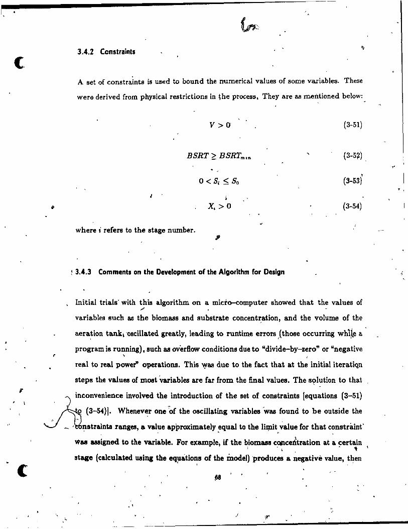
i.
c
,
i'
c
Il
3.4.2 Constraints
A set of constraints is used ta bound the nurnerical values of sorne variables. These
were derived from physical restrictions in the pracess. They are as m.entioned below:
V> 0' (3-51)
BSRT ~ BSRTmsn (3-5~)
1
0< S, < So (3-53)
, •
X. > 0 (3-54)
w here i refera ta the stage n umber. ;
t 3.4.3 Commenta on the Oevelopmént of the Aigorithm for Design
, Initial trials' with this algorithm on a micto-computer showed that the values of "" variables such ac the biomass and substrate concentz:ation, and the volume of the
aeration tankJ 'oBcillated greatly, leading to runtime errora (th08e occurring wh1le a . "
program is running), sucb as overflow conditions due to "divide-by-zero" or "negative ~
real to real power" operations. This 'YU due to the fact that at the initial iteratiQn
steps the values of m08t 'variables are far from the final values. The sc;>lution to that
Ainconvenience involved the .. introduction of the Bet of ~onstraints [equations (3-51)
q (3-54)]. Whenever one of the 08cillating variables wu found to be outside the " ~
-' ~straints ranges, a value approximately equal to the liJ;nit w.lue for that constraint' _ • .. Il ...
Wu usigned to the variable. For example, if the ~iom88S c~ce~tration at a ~ert~n
stage (calcula.ted using the eq~ations of the model) 'produces a negativé value, t~en \ '
, 1
" e'
.r
l'
T

a value equal to 0.0001 is assigned to that biomass concentration and the iteration
is then continued. This led to a significant reduction in the 'number of iterations . required for convergence to the solution values and it eliminated the problem of
computational errors. Cl
..
;'
3.5 THE COMPUTER PROGRAM
The atep-feed a.ctivated sludge modela, and the solution algorithm were included in a
computer progrâm, called STEPF, to simulate the step-feed activated sludge pracess
on a microcomputer.
The program' was written in Microsoft FORTRAN 77. This language was ebosen
because of its immense popularit'y in the scientific and engineering 'fields. \
The computer program consists basically of four sec,tions. First, the biodegradation
in t~~' aerat~~>n tank is modeled for the given constraints in effluent qu'Polit,. The
second section consists of the design of the clarifier for the given conditions (sorne • t
of them being results from the first step). Next, the auxiliary equipment for sludge
treatment (thickener, digester, vacuum filter, pumps) Îs designed. Finally, the total
cost of the project is evaluated.
, (, An opt,imization routine (Optimization is b~iefiy introduced in Chapt;; .î)--is used
to estimate the least--eost design. Once a ~ip alternative is defined, the design . variables ~ate4, for the whole system, and the total coet for t~e alterni'-tive ~
is computed. After analyzing a11 the alternatives in that way, thë minimal coat is , . , detemlined. " '
j'

,
l
c '"
The prog~am was written in such a way that a high level of flexibility is given to the
user, so that this i~portant requirement of the design engineer is achieved. Options » , ,
,were given for selection of alternatives in the fqIlo\\Û.J\i parameters or conditions: , - . • Biomass concentration: aeration tank average or last stage.
• Effluent BOD constrà.int: solublè or total.
• Sludge wasting location: aeration tank or recycle line.
• Volume of aeration tank: fi.xed or calculated. \
• System of units: Système International, (SI) or English. , . . ~
~ Cost optimization: no optimization, optimization of the recycle ratio, opti-
mization of the biomass concentration, and optimization of b.oth paramete!s . . . ' ~ .....
Additionally, a large number of system parameters can be updated by the user.
Default values are suppUed in case the user does not have that particular information. , - t~-,/ ,
These data are supplied in files denoted STEPF.DAT and STEPF.FIX. The results~.
are retained in a file named RESULTS.REP.
3.6 RESUlTS,
"
3.6.1 ComPirlaon of Resulta wlth L1terature
0,
• • It ois con~nient to compare the results obtained in th~ research \:Vith those reported in
the literature. The STEPF program h88 been run with data from numerical examples ..
found in the following studies.
, ,
Buhr et 01. (1984) presented variations of the soUds distributions with feed point in '\ f ,
& four-pua step-feed plant. Comparison of the Buhr et al: results with simulations
70

l Table 3.1 Comparison of Results with Literature - Biomass Distribution. 1 ' ~~I
, l .".
InftoVi Distribution Recycle Biomus Concentration (ms/L) Source
al a~ as a" Ratio Xl x~ X" x. , , -,
1 0 0 0 0.3 1000 1000 1(}()()j. 1000 B . 985 1000 1005 1010 M
0 1 0 0 0.3 2350 550 55O. 550 B 2310 • 555 " 565 575 M ...
0 0 1 0 0.3. 1620 1620 380 380 B • 1625 1.580 390 "05
\ M
" 0 ° 0 1 0.3 1240 1240 1240 .280 B
1380 1230 1100 290 M~
1»
1 0 0 1.0 5000 5000 5000 S (.
4980. 4995 5000 41
! ,1 .! 1.0 6100 4800, 4100 S \ 3 3 3
"9 6115 4910 4100 M .. •
\: 0 ! .! 1.0 6900 "600 3500 S ~ 2
6945 4645 3500. M
~ la 0 1 1.0 6000 6000 3000 S
J' 5980 5~ 3000 M
l,
. B = B~t 01. (1984) 1-S ,= SOreDJeD (1985) " -.
"" /
M = Model r
~
'8 ~
~btain~ with the model of ~is study showed a devia.tion no areater than 11.3%,
with an average deviation of 3.~%(see.Table 3.1) . '
SjZJ~ensen (1985) sÎIDulated a three-pus step-feed plant. He reported results of lolids
-~ ~ 71
"

(
1
J-
-,
c
distribution along the aeration tank for different feed modes. His results are within a
2.3% deviation compared to predictions by the model of ihis study with an average . deviation of Of8% (8ee Table 3.1).
Table 3.2 Comparison of Results with Literature - Ratlo Xa / Xn. j... ,. 1
Inflow Distribution
0.25 0.25 0.25 0.25
0.25 0.25 0.25 ' 0.25
0.25 0.25 0.25 0.25
-0.00 0.00 0.50" 0.50
0.00 0.00 0.50 0.50 0.00- 0.00 0.50 0.50
;
W = Wi1ber et al. (1980) M = Model
D = Ditference (%)
,
Recycle
Ratio
0.05 0.30
0.60
0.10
0.30 0.60
Ratio Xa / X'; ... W M D
2.0 1.9 -5.0 1.6 1.5' -6.3 1.4 1.4 0.0
6.2 ' 6.2 0.01 2.9 2.8 . -3.4
2( ).9 -5.0 ...
...
.... -- ~ / ~ -,~
,..,.~
;~ L...
Wilber et'al. (1980) showed the effect of diverse feed modes o~ the ratio, of average
soUda concentration to last-pass soUds cOientration, in a four-~ass s~~p-feed plant.
The _d~viation between bath models is low~~!'ll or equal to 6 .• % for aIl of the cases / ,
presented (s~ Table 3.2).
Wilber et al. also studied the oxygen demand profile for a plug flow feed .mode ~ ... '"
and for a standard step-feed mode. A comparison of the data presented by t,hese ~
authora with thoee, obtained in this study is pre'Sented in Table 3.3. Even though /
the difference between both predictions is in BOille cases as high as 30% (the average , .
12
,.

-.. ', \.
\ 't>
o
\
deviation is 13.0%), the profile of the oxygen demand along the reactor is ~iJriilar in
both cases.
, .'
Here, it is convenient to mention that the oxygen demand profile along a reactor
depends on both the mixing regime and the 'feed mode. The differe~t oxygen demand t" '. profiles resulting from cotnb~nlti~ns of t11ese factors are shown in Figure 3.6, for both
theoretical and simulated results. T~c: difference between theoretical and simulated -.p-.
\.. results is due to the .......... "tlon taken in tI:e development of this model th.t e""h
st~ge of the aeration tank be)laves as a complete rilix reactor.
~ ,
Table 3.3 Companson of Results with Literature - Oxygen Demand.
1
- . . Feed Mode Source % of Average Oxygen Demand
plug Wilber et r,l. (1980) 200 110 50 35 ;
flow Model 185 110 65 "0
DlfFerence (%) -7.5 ,. 0.0 30.0 14.3
/
f~ard Wilber et al. (1980) 125 105 90 80
etep-feed Model 110 100 95 95 '-<>
'""" >! Difference (%) 18.8
0
, .. 12.0 -".8 5.6 v
" "
,
Andrews (1974) simulated a four-pau step-feed plant with secondary clarifier. He
pres~ted ~ for steady-state conditions under different feed pattel1ll. Si.milar
results ef biomus apd substrate distributions, IfSRT, and, VT were obtained using
the model ptesented here (~ Table '3.4). However, due to the different kinetics
used by Andrews (Monod's kinetics) and in thit"fesearch' (ftnt-order kinetics), the . :. ....... '
13
\
\
, t: .. "
.}

~ C1 Cd a " Q
C1
" ~ 0
\
PASS 1
<C,
• 0
"-
.,
1 E1
,QI
ca
e f
PASS 1
C
l'heoretlcal Plug Flow Regim47 •
Feed la Pass 1
'1:1
~ s .~
C1
" ~ 0
PASS 2 PASS ,3 PASS '" PASS 1
(a) Feed to Pass 1
Theoretlcal PIUI Flow Rellme
Slandard Feed
'd C1 al a u i:I
C1 QI
~ '~
0
p'
.' , PASS 2 PASS 3 PASS ... PASS 1
(h) Standard Feed
Sim'ullllion Resull!!
Feed lo' Pass 1
PASS 2 PASS 3
Q...)
Simulation Reluits
l
Slandard Feed
II'
PASS 2 PASS 3 '
Flau,re 1.8 Oxygen\ Demand Profiles for Differen~ F~-Modes.
"
J
PASS ..
. PASS "

;jS" ~ '.
\ \
. . .ut~ ...{.(. J biokinetic coefficie~ __ ed are dift'erent in each modela Resulta should be carefully ,
compared since both equations predict the same results only when S, is much smaller
than K., but the numerical simulatiots presented ~herein show that this is not the
casE1, specially for the plug flow mode. )
Table 3.4 Comparison ?f Results 'with Lit.er~tul1e - Biomass and Substrate Distribution.
-BiomUl Concentration
(mg VSS/L) Substrate Concentration Source
(mg BODIL) Xl X 2 X s X, 81 82 S3 S,
1
Inflow fraction to puaes = 0.25 - 0.25 - 0.25 - 0.25
4010 2690 \ 2030 1630 6.0 9.0 12.0 14.0 A 4010 2687 \2028 1634 6.5 9.0 1 11,6 14.0 M •
\ ------------~------------~------~-------------! , '\
Inflow fraction to pUla = 0.00 - 0.50 - 0.50 - 0.00
7850 2660 1620 '1620 0.1 18.0 28.0 8.0 A
7848 2658 Ib21 1624 0.1 17.9 27.0 8.0 M \ \
1
A = À.Ddrews (1974)\ ~ '\ M = Model \
/
\
3;6.2 Other Results 1 )
1
Other results obtained with the 'program STEPF are analyzed herein. 1
TranAition Recycle Ratio;
Figure 3.7 shows the area of th~, settlin, tank u a fu~ctlon of t~ recycle ratio.
75
, 1
----_ .. -----------------------------

c'
/ / /
2500
,-.
e 2000
cd 1500, Q) ~
-<
0.20 0.30 0.40 0.50 O.sO Recycle Ratio
, -Figure 3.'1 Area of Settling Tank as Function of Recycle Ratio.
,
The curve shows a minimum area which corresponds to a ratio derioted' here as the ','
transition recycle ratio. In the region corresponding to values of R lower than this '" -
value, the thickening process controls the solids-'Separation process. In this region, ! , '
the area requir4UD.ents are highly influenced by the recycle ratio. For values of R
higher tban the transition recycle ratio, clarification controle the separation process.
The area requirements here are not as dependent on R. These results correspond to \ ,"
the input data presented in Appendix D.
NUmber of Stages;
Th. number ofstag .. of th. aeratipn tank directly" affects the v)ume ofthe aeration
tank and the area of the c1~ifier. Figure 3.8 8h~ tn.e results 'obtained for aeration
tanks with two to eight stages. These changes in the aeration tank volume and
secondary clarifier area will have a direct effect on the total coat of the treatment
'T6
, .

•
o
plant. This point will be discussed in Section 4.5.5.
Feed Mqde. B SRT and Removal EfficiencYi
Table 3.5 shows the effect of the feed mode (alpha coefficients) on the biological
solids retention time .. and removal efficiency~ As mentioned before (Section 2.4), the
same effluent quality, measured as either total (BODel!) œ- soluble BOD (Se), can
be obtained with different feed patterns. The results show tha~the B SRT for each
different feed mode is also different. This indicates that selection of the -B SRT for
the design of a step-feed plant does not ensure that a desired efficiency or effluent
quality will be obtained, even when the average biomass in the system (and therefore
B SRT) increases for the standard step-feed mode when compared to the plug flow
mode. . ,
Table 3.6 Feed Mode, BSRT and Effluent Quality.
Inflow Diatribution Simulated
BODel1 S. (mg/L) (mg/L)
-0.25 0.25 . 0.25 o.~ 30·/ 25.1
~\0.5O 0.50 ' ,0.00 O. 30' 1 25.1
0.50 30' 25.1 0.00 0.50 0.00 0.00 0.50 '0.50 0.00 30" 25.-1
0.25 0.25 0.25 0.25 16.9 12" 0.50 '0.50 0.00 0.00 16.9 12" 0.50 Q.oo 0.50 0.00 16.9 12"
'0.00 '0.50 0.50 0.00 16.9 12"
, BOD.11 UNd _ input parameteJ'
•• S. UHd u input parameter
71
-- 1 ('
3.87 0.88 1 1.61 3.23
10.10 .
1.29 2.76 5.51
\
.\ .\ , __ ._. __ , _____ ..1.-____ --::....-________ ..... ____ _

",
~
C 40000 "
~l.. ~ ,-~ ~ 35000
(,,) - \ 9 3Qàoo -~ 25000
l 2000~ ~ 0
:; 15000 ... ~
10000 2 3 4 5 6 7 8
,Number of Stages
~
'(a) Volume of Aeration Tank " ,
\
6000 /
5000 . l,. - .
\
~400p ,
III -~ 3000 ~
.! 2000
~ 1000 ' ,
_1
-' >
0 ,.J 2 .3 4 5 6 8
Number of Stales
(b) Area of Settling Tank
Flg1ue 1.8 Eft'ects of the Number of Stages.
(. 78
'11"
~ ,.
J

-e \
CHAP,TER' 4 ."
DESIGN ANQ OPTIMIZATION
One of the purp08es of this research is ta integrate the mathematical model developed
herein to an optimiz,tion techniqu~, in sucb a way that it can be used by d~sign , - '" -engineers to find the va~ues of the operational parameters that yield a least-cost
~ , J,
design of the step-feed activated sludge system. o ,
Q
In this chapter, optimization techniques are first briefly reviewed, a~ng with their
applications in the design of wastewater treatinent plants. Then, a methodology for
cost-effective design of step-feed a.ctivated sludge plants is pr~ent~d. The model J
used for the simulation of the system is that developed in Chapter 3.
The following terminology will be used in this chapter: (>-
• System parameters: ~h08e quantities that repreaent input conditions to the
design/optimization problem. Their values are' intrinsic to the characteristic8
of the treatment system .
• . Input variables: those variables that are independent Crom the characteristics
'" of the treatment system. They are input conditions that c~ he usigned
arbitrarily with a feaaible val~e.
79
,

"
( \
c
, ) • Design variables: those variables to be estimated by the mod.el. They res~lt
• from modeling the system for those conditions given by the syste!D- parame-
ters and variables.
A U;t of the system parameters, input variables, and ~os_t important design yariables
is sh.own in Tabl~ 4.1.
\
\
.-
Table 4.1 Parameters and Variables used in the Design.
SYSTEM PARAMETERS: _________________________________________ 0
!nOuent Flow, Qo !nOuent S"ubstrate Concentration, So Ratio VSS/SS Biokinetic Constants: Y T, K, kd
" Siudge S'e'~tling Characteriatics: Vo, ft. Amortilation Period and Inter~t Rate, p ~d int
'\ INPUT V:ARIABLES:
Flow mode, a's Recycle Ratio, R
Biomus Concentration: :>ca or Xn
DESIGN VARIABLES:
Aeration.Tank Volume, VT
Biological Solids Retention Time, BSRT Biomua Concentration per Stage: Xl, X" ••• , Xn Sube~rate Concentration per Stage: Sl' S" ••• , Sn Biomua Concentration of the Recycle Line, x,. Soluble, Insoluble and Total Effluent BOO Sludge Production per Stage, p s •i
Oxygen Requirements per Stage, 0, .• Siudge Wasting flow, Q.,G or Q.,r Area of Clari6er, A Overflow Rate, ORA Aeration System Capacity Recirculation and Siudge ~umpa Capacity Gravit y Thiekener Are .. , Age . Anaerobie Dig~ter Volume, V dig
Vacuum FUter Area, A.t 0
80

--.,.
1 -
, "
. ,
.'
,l
'-- . J
4.1 , OPTIMUM DESIGN
"
o ,.
Generally, ,the final selection of a. treatment system is based on 'bot.h the technical . , "
performance of the system and on an economic evaluation ,of it. When~ver sev-'~
. eral alternatives give appropriatj! and similàrly 'acceptable results, from 'a technical . .
_ viewpoint, an ,~co~omic study May, be undertaken in order to select the leut-cost
treatment system.
The. mathematical model for a standard optimizatlon problem, where limited re
sour~es have to 'be optimally aUocated among competing activities, May ~e repre
s~nted as follôws (Hillier and peberman, 1986): "
opthnize
z = l(x1tz~, ... ,z,.)
. J \ (. subject to the'restrictio~
for i = 1,2, ... ,m ,.'
(4-2.a) n .~
and
..
~, for i = 1,2, ... ,le (4-Z.b) .
where the oP'timizatio~, termed the objutive lunctjon~ May co~ist of the 'maxi-,
mizatidn_or minimization of a particular problem. The le variables Xl' Z" ••• , z" are " 1
, calI,!'!d decision variables. The restrictions ordinarily are called constraintl, These are
the mathematical representationS of physical or functional constraints.
\ , When optimization techniques are applied to process design, two dift'erent objectives '
~
l '
May be established: (1) to maximize the efficiency of the prOCeB8 or (2) to miniinize
81 j
\
'; )

~ ..
,.
costs. Both object1ves2are usually -injçppositi,on, tITat is, better efficiency requires
a larger' cost, and vice versa. In the case, of a wastewater treatment plant, the
efficiency required to meet t~e effiue~t quali~\standards can generally be attained,
without technical limitatJons, by processes such as activated sludge. Therefore, the
optimization is ca~ried out as a costs minimizatiort (objective function), while the' «<> - T
removal efficiencies for pollutants lik,e BOD and SS are represented ir the optimization
problem by ~ set of constraints.
The objective function for the cost minimization of a treatment system, should include
both capital and operating and maintenance (O&M} costll. Capital' cost8 are those
associated with the initial investment. The mostOimportant to consider are purchased ~
equipment, buildings, land, construction expenses, as wellas engineering, supervision, ./,
and contractor's fees. On the other hand, O&M costs include raw materials (e.g.
chemicals), labor ~ages;or opera~on and maintenance, power and utilities. "
As mentioned earlier (Chapter 2), many kinds of biological wastewater treatment sys- ,
tems can.. be used for final treatment, because they ail can achieve the effluent quality
standards established for secondary effluents, Even within a "pecific system, 8uch
as activated sludge, ,alternatives such as \ifferent modifications of ~he convention al
process, and different operational conditions, yield feasible designs that achieve the
water quality goals. Studies of cost~timization have proven that this is an effective ~
tool for design, with reported savings as high as 25% compared to more conventional fit.. /
design methods (Tyteca, 1985; Tang et al., 1987b).
Nevertheless, Craig et al. (~78) pointed out that m08t treatment plants are designed
without ,analyzing the diffe:tnt combinations of individual treatment unit. that would
determine the least';'"C08t des' . It is important to note that in order to obtain' an , ,
optimum design for the ove aIl system, individual unit. cannot be evaluated sep&- -
, . 82
1

c
, \
\
rately, sinee considerable interactions occur among the unit processes '(Par'kin and .,..
Dague, 1972; ; Suidan et ~., 1983; Tang et al., 1~87b ). , ...
Mathematical models for cost optimization of wastewater treatment plants have ap~
peared in the literature sinee 1962 (Tyteca, 1985). These optimization studies ~on-1
sider either parts of, ~r. t~e ~h~le treatment plant. Rossman (1980) reported tlia:t in
a group of waste treatment system models, the majority do not integrate wastewater
and sludge treatments.
Initial optimization studies frequently considered only two or three of the most im
portant processes of the plant. ~rickson et al. (1968b) modeled an activated sludge J
system 'consisting,of an aeration basin and_ a secondary clarifier. Parki~ and Dague ~ .
(1972) included a primary settler, activated sludge, a final settler, and a digester in
thefr model. More recent studies integrate -almost ail the significant prpcesses of the ~
treatment. Optimization modela that incorporate aeration basins and aerfLtion sys-
tems, primary and secondary clarifiers, recycle pumps, thidœners, digesters, vacuum
filtera, and sludge disposaI- facilities are frequently round, mainly in recent literature /
(Middleton ,and Lawrence, 1974; Cr~ig et al., 1978j Rossman, 1980j.Tytëca, 1981;
Suidan et al., 1983; Tang et al., 1987b l'.
4.2 THE OPTIMIZATION Of A STEP-fEED AC,TIVATED SLU~GE PLANT
As mentioned previously (Section 3.4), the model presented in ~his <study has three
input variables, that is, there ar~ three degrees of freedom for the design. These are ,.'
- the in~ow distribution coefficients [i.e., the ",.alpha (a) coefficients], the recycle ratio ,
jR), and either the average (XCI) or the lut stage (X,,) biom&1!8 concentratio~.
83

"j),"\
" 1
. -The aim M'th'is éhapter is to apply an optimization technique to the model developed
pin Chapt: 3' to obtain a least-cost design.' F~hat Plirp'oSe~he values of th~ alpha , i.. i • \ ,
coefficients }'Vill he considered as a systèm parame ter in the modlt'. This decisien was
based on two reasons: (1}-it was round that using three variables in t'he optimiza- -
tion process lincreases the computing time of the iteràtive procedure to sometimes . . prohibitive valu~s, an~ (2) the design feed mode should be :stablished accordirtg to
, the characteristics of ~ wastewater (e.g. influent substrate concentration, soluble
fraction), -the desired efficiency and stability of th'e process among other factors.
/ ' , (
The remaining input variables are the recycle ratio ahd the biomass concentration.
These variables have,been customarily used as input variables in mathematical models >'
for the deSign of activated sludge syst~ms (Lawrenée and McCarty, 1970; Mynhier .. and Grady, 1975; Benefield and R.andall, 1980; Ong and Lee, 1987). Since the flnal
settling, t~k size is directly influenced by t'he 'recycle~ratio (as predicted by' the "
solids fl~ theory and Chapman's clarification mo~el previously reviewed), Many
researchers have used these, as weIl as oth.er factors, in analyzing tradeoffs betlween
the aeration tank and the secon~ary clarifier in order to ohtain a least-:cost des,ign . ~
of activated sludge treatment plants (Middleton .and Lawrenc~, 1.974; Grady, 1977; "--- .-
Craig et al., 1978; Rossman, 1980;' Stenstrom and Andrews, 1980; Tyteca, 1981;
Tyteca and Smeers, 1981; Suidan et al., 1983; Tyteca, 1985).
_ The feasible region is defined here as aIl the points on' the recycle ~atio/biomull co~
centration plane, for which the design solution satiafies aU the specifled constraints . •
Application of optimizat~on techft\ques to a particular problem requires the 8el~ti~n
of the objectiv.e function, the' decision variables, and. ,the constraints. The deciaion
v~ia!>les may he consiqereq as thoee deiign variables which ilirectly affect the ob
jective function (e.g. aeration tank v~lume, clarifier area). The constraintl can he , .
\
(.
! , i

, q
c'
J
., "
, ''''
(
"" ..
J .v
derived from physical or operational restricti~ns affeÇting the process. c..- . '
In addition to the aeration tank an~ the secondary clarifier, other. proçesses or units
included in the optfmization are: aeration system, recirculation and sludge pumping J , ..
oC> " systems, slu~e aerobic digestion, and vacuum filtration. Preliminary treatment anà
~ , primary sedimentation were excluded because being upstream processes, it can be
• u
assumed ,that they di,0t affect the optimization of t1Îe aeratioh tank/ secondary
clarifier. The only co .. quence ~f the previous ... umption is Ùl:,t the total c~t obtained does not co espond to the cost of the whole treatment facility.
- ~ , , -,
4.2.1 Cost Evaluation
Cullinane (1979) identifled four levels of cost estimation: the "horseback" estimate, . ' .
the planning estimate, the engineering estimate, and the contractor's estimate, also ,
known as the fbid". F~r cost-effective prelimi~ design of step-feed processes, the . . . coat estimate should be carried out at the planning level, as it will hereafter.
" . The planning estimate is based on knowledge of the basic system !ol"mulation. Two
,
methods can be utilized for ~hat objective. Firs't, parametric cost estimation is a
statistical approacli where cost is a function of a limited number of variables (gen-. - . , !,
erally gnly one, e.g. flow, volume, surface area}, obtained by statistical analysis of,
similar facilities. The second method is the cost element approachj here the user in
puts unit costs information, such as coat for building, excavation, and land, priees for 1
coricrete, pipe, chemicals, and electricity, and labor wages. AnJntermediat~ position y •
is rrequently adopted where some important cost, elements, BUch as labor wages and
, 'elèctricitf, a:r~ set as input values in the parametric cost functions (Middleto~ and
, ·:C '- ',' Lawrence, 1974; Cr&lg ) al., 1978; R:_, 19~Oj Tyt~~, ?9.81\. • ,
~ . 85 9
, . \ ,

-0 1 •
r ~ • .... _~ t _
~'\ {11'2 fI:~I:, l' ,_,_
~ ---., -'-'
The '~ost functlo,ns should be simple and reliable. The simplest function tener",lly , <'1" ~ ~ .
giv~ the bést 're~ults (Spaine and Walski.., 1917). The data used should come from \ . \\ , "
heterogeneous sources (i.e., different time periods, locations,'manufacturers) t'e be • q , . ' , ..
applicable to general estimates (Tyteca" 1985): Whe~ using existing coat functions, . .
the qriginal source of the cost data should be known. In this way, ail the 88sumptions ,
mad~ and the costs included can also be known. Most cost relationshipe are of the
form ~(Spaine_and Walski, 1977j Ty:teca et al., ~977j Arceivala, 1981): )
where
, COST = cost (capital, or operati6n.and maintenance), dollars --, D = design variable which most significantly influences the COflt . ,
1 ~
Cl' C:a = estimated constants, dimensionles8 1. - ~
. w~n the shape of the curve changes considerably ,~er a ~ide range of th~ d ign
varIable, it is tecommended to sJ?iit the who le rang~ of D into several sections and
, to fit curves to eéÎch sectiQn (Spaine and WaI8ki,~1977).
o
It is important to n~te that the use of coat functions that relate the coat of the unit
process to 8i~gle variables like influent flow rat~, organic 10ad, -or eftlClency, by\UIIe8
the relationship8 that describe t~e ~erformance of the' syiStem, therefore they cannot
be used·' to optimize the proces~ performance. Furthermore, these coat functions ~ 1 ~ ,
frequently have poor correla:tion coefficients (as low as 0.52) and should be Uled only ,
for rough preliminary estimates (Dames and Moore, 1978a an~ 1978b). ~ ..;r '" ':t) ,-' -,
f ~ ,-
On the other hand, cost functions that relate the coat to design variables can be used f'
in the optimization, and also appea:r to be more reliable (Tyteca et al., 1977). Never-
theless, tl}is C08t infomiatlon is mainly available through con.st~~to~_and consulting -({
8& , .<
-~--------------------------------------------------....

•
c
,l
) f' J
I,
..
c (
firms, while publications are scarce. Smith (1968)' compilea available cost information \ ')
and presented it as both global (whole treatment plant) and indiv!dual process costs.
The costs of preliminary treatment, return pumping, c~lorination, auxiliary facili-'.. ,. .,.,
ties, and land requirements were presented as' a function of pJant size, while costs fo~
influent pumps, 'p~ima.ry~and sec~ndarY ~edime~tation tanks-, aeration tank, blowers, - , ' .
digesters, and vacuum filters were evalùated as func'tions qf their design parameters. • '. Q
Patterson and Banker .. (1971) presente~ datL in grapnic form, i'Or prelimin"ary esti-~ , A"
" 1 ~ .",")
mation of construction and other initial investment capital costs for 21 major pJant , ~ . . \
çomponents, as weIl as operation and maintenanc~ costs for 15 individual compo-. . . , . nent.s ~~f tr~atment plants: This is one Of the most comp.Iete and reliable pubfications
1\- 4 • ~ \
on wastewa.ter tre1s.tment cost estimation. .1t has "been used as the source i>f cost
informatioror many studies in 'wastewater, treatment ~ost analysis and optimization
(Middleton and Lawrence, 1974j I}einath et al., 1977j -Craig et al., 1978j Ketchum et
,> al., 19~9i Tyteca, 1981j Suidan et al., 1983; Tang ~t\al., 1~87b).
To carry out the optimization, the model dev,eloped in Chapter 3~equires detaited
cost infor~atiori for each of the processes of the treatment plant. The costs sho~ld be·
functions of the design parameters, such as aeration basin volqp1e, clarifier area, etc.
Also, to give Bexibility to the model, it should allow the input of variable operation'
cO!lts, s.uch..as wages" electricity cost, and other significant coat factors. The st~~
presented 'by Patterson and B~ker satisfies these requirements and ispselected here
as t~e 8~urce of cost information for the economic optimization of the step-feed
activated sludge design. " \. t; • For. th. pllfpoeJ of Îhis study, cost iunctions' for th. fon:Wing proc..... WeIe nec-
essary: sedimentation, a.eration basin, aeration sys~em (diffuSed air), recirculation
p~ping, sludge pumping, sludge digestion, and vacuum filtration. In addition;\cost
o -. ( 87

1
.. .
('
•
o
'fl1nctions for die Most signifièant additional expenditures, !luth as ,engineering and " -
contractor.'s fees, contingenciès and omissions, and e~t of land -were taken from the , "
work.presented by Smith (Î969). ""i: ,
Analy~al expressions of the cost dat~, ~resented in gr"'aphic fo}m by Pa't~~rl!lon and •
Banker, were developed by Çraigd al. (lQ78). The cost'functions for the diffused-â.ir
a~ration syst-em, not presented in this last reference, were direc~ly obiained by linear . . . , - "\.. regression of thé data. The cost functions for t,he different components of the 'plant
and for the ~additional expe~daures arllfpresented'in AppendiX. C.
" G When éomparing--several dlfferent ~lternatives of a proj~t where the initial invest-
ment (capital coat) an~ the annuities (O&M: c~sts) are usually different ,for ~ach case,
it is common practice to detérllline the present worth of eaclr'alternative and ,then to .. '. , ,1
. ,;' 'malte the comparison. Thus, equation-(4-1) c~ be expressed as ~ .
Z = (total càpital costs) + (total annùal costs)(present worth factor) " (4-4) r$'
l.
..,. ç
Det~ils about' the eStimation of the present worth and present 'Yorth factor are ,.ven
hi Appendix B. a -
/ .Also, importance should be givell to obsolescence of the coet .data. Most cost in
formatio~ available for economic analyses is outdated, because.prices of equipment, /' .1' t
materials, power j etc., change considerably w1th time. Therefore it is necessary to -:,
update this information· to make it .useful. This can be accompli~hed f~irly aècu-
.rately by the use of cost indexes. Although cost indexès do not take into account
aIl f~tors (e.g. ,technologi~al advancements, local conditions), they give a general'
1 • estimate, useful for preliminary design. analysla. The use of coet indexes il detailed
~ Appendix B.
ss'
,
" <1>'
(

!
..
•
. ./
"-)
c-~ , y
1 / .v' !.
/
! " /
-\
, <;-
4.2.2 Other Consid'erations t
1
'~ Th4!! unit processes for sludg~ treatI}lent must b~ designed to include their costs in ;he
C ,
", J f·
., J \.
objective function. Nevertheless, the optim.ization of these processes is- beyond the 'lI -
objec.tives of this !esearch. The~efore, a conventional procedure is used for the design j, '. ~
of each component. The.procedures used in U\;:is study for the design of processes . . ",.. -LI f (1
other than the aerati~n tank and the secondary -darifier ~e ~resented in Appendix A. L. \ <
'\ ., . ~
It Î8 common practice to use an excess capacity factor (safety factor) f-or each of '" 1" •
\ .. the unit 'prOÔeBses of the facility. Once the unit processes are designeq on a steady-
;state buis, excess ~apacity should be provided to hahdle peak conditions w1thout
déterioration of the effluent quality beyond the standards or quality objectives. In . , \ (
this study, the safety factors used are those report.ea by Smith (1009). They are
.. • presented in·Table 4.2. #' , . .
• w,
Table 4.~ ...
o •
fi,' e f .
'" .. -" . . EXCèSll. Capacity Factors for Desigp in Wutewater Trea.tment.~"
.., - "l-
I·
Unit Proceu • '.
Safety E",oACtor
L
Aeration Tank 1.20 Aeration Byetem 1.50 o ' ,
SeUling Tank 2.00 . a. Recirculation Pumps 2.00 ,
Sludge Pumpa 2.00
Gravit y Thickener 1- 1.50 '1>
Anaerobie Di,eater 2.00 Vacuum Filter 1,00
"89
.-

\
1
\
,
1
. t-"
D -
o
. .
"
il, • l '
, .
" "" .
• ; J ~
t\ .." .. "
"
Aft~r co.n.~dering b~th.the pres/nt,worth facto~ aJl~ the safety facto~ for each ef th~ .
unit'pr,ocesses ~o be includedin this researc~, equation (4-1) can b~ written as:
• t.' / . , , .
,= . '\~' 'Capitai Cost(SF, x Xi) + PWF X .' E /.o&~o~t(SF.. x x,) ail procen.. ail proc .....
where "
,. (
/ . ,. -O~,TOT = total oxygen requirement, kg/d
, -) 1
, ,
p.,TdT = t~ta! excess sludge'-production, kg VSS/d
Age = area of gravit,cy thickener, ~2
Velig = volume of the aerobic digester, ms'
l) l' 4.1 = area of vacuum iUter, m~ Q .." •
.'
S-F. -l , safety factor for procees i ~
Xi = decisi9n, variable i
#>;J .. , ,
, r
Thé c<?~traints' U8e~ in this study ~an be.expressed as: , . ,
. ,
( , \ . ,"
'. 1
BOPTOT ~ 30 ,mg/L
c~ S o.oà 'g/L r
and o
\
.. ,VT , A., R, Q., 02,TO.T, p.,'I' 0 '1' ,A,;' Vell,,', Ât" ~ 0
( . " 90
• . q.
, ..
• 1
(4-5)
..
• *
(4-6.a)
'(4-6.b)
(4-6.c)
( /
, Î

,
\"
" ,
....
( (
.. 4.3 OPTIMIZATION TECHNIQUES ,
.. " 4.3.1. App~lcations in Wastewater Treatfl\ent " j, ..
• ~_ ,. 1 • , _ -( ..... , da . 1
fu the field' df wastewater tfeatfnent, ,; large n~er of differ~nf i~1Î.niques have been , .
used to solve optimization algorithms. ~hese methods in~l~de: li,!1e~r progr~ipg, . . .
nonlinear programming (e.g. generalized reduced graàient, sequential quadratic pro- . .
gramming, geometric programming), dynamic pl'ogramming, the simplex search te~h-, .
.......... ~.....6;eii'",-g'raphical parametric enumeration, the discrete.ma.ximum princip le, simula-~ ,
., tion, golden sect!oILsearch, implicit enumeration and complete enumeration (Tyteca ~
et al., 1977; Rossman, 1980; ~Tyteca, 1985; Tang, et al., 1,8~a). Many of thesê
teèhniques have not been extensively àtceptéd for design because of their drastic 1 ... Q .. •
limitations (Craig et al., 1978). For linear programming, ail the functions must be
Uneu; dynamic programmh\g has limitations when recycled streams are eonsidered,
and whe~ltiple p~l~tants are stud~eaj nonli~ear programming pr~duces~multiple ,~
local optima, depending on the atarting point, the bounds on the variables, and othèr
initial conditions; enumera.tion techniques sometimes require considerable computing ..
., time. r..-'
. ,
Tyteca et al. (1977' classified the optimization models itiio two groups: (1) the -~ . economist-operations researcher group, chara.cterized by highly elaborated optimiza-
• CI' ~ l' •
~on techniques a.nd strongly si~plified mat~e,m~al n:,0dels, ~ ... d (2)_ ~he bi~log~t-
mathematician group, d~eated by trivial optimization techniques and elaborated . • m&themati~a.l ~ode1s whJch attempt to describe a.ccurately the operation of the plant.
,
" 91 ~
( 4M
• 1:1 \ <--

-
,~
.,
4.3.2 Opti~mizatiol) Technique,Selected
.. . /
' 0
" ,
.Q "' "
1 As oa result of the relative çomple~ity' of the model th describes the behavior of
a step;-feed aclivated sludge.' plant, and because it is n one of the objectives, of . « .this resefch'to analyze the applicability of different optlmization ~~hniqueB for this
parti~ular case, complete enumeration was selected as the optimization technique to ~) ') ~
, " as most useful for design engineers. '.
L~e. used {l the le~t-cost de~ign. Parkin and Dague (197
S co~sidered this method
o '1 ,.,,' 1 .. b ' ..
For tfFe ~omplete enumeration tec1:!nique, the range for eacl(input variabl~ to be~ . . ' . optimized is ~lit into a specifie number of'segments. The design space is defined as
the set of aH possible combinat ion; of the input variablês. r:r*tal coat is ~stiinated for
each alternative of the design space, in §;arc%o e leas~ost design. This technique "-
has, been successfully applied to the optimization 0 w~ewater treatment systems ~ ~ by Parkin and I?ague (1972), Middleton and 'Lawrence 1974), and by the U.S. Army .
Corp of Engineers (1915) with the CAP:QET computer ogram.
~ng and Lee (~987) stated that, because ~omp'lex techniques often require Itarge
~ amounts of computer resources, they' may not be suitable for ,implementing on a riii-~
crocomputer'10n the other hand, complete enumer8;~ion ro~tines, li1re t~ one ~sed in • 1
this reseatch, can ~asily be implemented. Thus, one of thè major dlsadvantages of this
t~hnique (large c~puter time requireme~) has diminished signifi~antly' nowadayÇ • due to the actuaI high performance-Iow cost feilture of ~odern personaI computers.
. \ ..
, .
.! d
t

C 1 , .
. ' . .
-/
..
c
o •
4.4 DESIGN OF A STEP-FEED TREATMENT PLANT t
In this section, somé design ëxamples of step-feed treatment plants will he illustrated . ,;'
çThe computer program and m,ethodology presented in this research ~ill be used for
that purpose. AIso, other results ohtained ~ith the program will be presented and "
discussed.
4.4.:1 D'esign Exemples , ç;
.. 1. No Optimization
Q
Designfa step-feèd..: ~reatment plant capable of handIing 50,000 m3 / d of domestic
wastewater. The waste has a total soluble organic content of 400 mg BOD;/L. The
quality standards require an effluent with a total BODs con~entra.tion lower than ~O
• • ~g/L, and a SS concentration c10wér than 30 mg/L.
The wastewater ~as the following characteristics:
r
Ratio VSS/SS = 0.75
Settling coefficients:
Va = 15.0 cm/min
ft =' 0.6 L/"g (
Biokinetic coeffitients:
Ye ='0-.60 mg VSS/mg BODa
/cd = 0.04 day-l .!. , K = 0.03 L/mg·d
...... ----
, The' plant will be oper~ted in the standard step-feed mode. The aeration basin is
, 93
Ct
R

"
" divilled into four stages, e~lvwit}t equal.volume. The shidge is w~ted from the
• 0
recycle line. •
J Me~calf and 'Eddy (1979) reported the following r8.I!g,es of typical de~ign values for
Q
"'the recycle ratio and the MLSS (average SS concentration in the mixed liquor): , ,
MLSS = 2,000 - 3,500 mg/L
R = 0.25 - 0.75
'1, • j;)' c
For design purposes, values of 3,000 mg VSS lb for the biomass concentration (equivt ... , , ~
aLent to 4000 mg MLSS/L) and 0.50 for the recycle ratio were selected.
~i.
The service life of the plant is estimated at 20 ye8.fs. The interest rate is 9%. 'the
cost index ratios for construction, materi~ and ~killed labor are 2.994, 3.005, and,
2.812 respectively (see Appendix B for ca1cuI~,
~ith this information, 'the computer program\r.,r the design of •• tep-feed ;ant i. . ;
executed. The steps to follow are: .,
1. Introduce the above information in the file STEPF.DAT. é:~
2. DExecute the program STEPF:
,:,' respond to the optiniization prompt with "0" (no optirpization). p
3. Display the file RESULTS.REP to see the results of the design.
, The results are shawn in Table 4.3. , .
\ 2. Optimization of the Recycle Ratio • \
v ~
For those conditions given in ExampJe r~o. 1, design,a step-feed treatment plant,
but minimize the total cost of the plant for values of the 'recycle ratio ranging from
0.1 to 0.8 (use a 0.01 step). ',' ;' o
t
\
, '

The steps to follow are:
1. Introduce the given information in the file STEPF.DAT.
2. Execute the program STEPF: .
- respond to the optimization prompt witl} "2" (optimization).
- select R (recycle ratio) as· the optimization parameter.
- introduce the range and the step for R.
3. Display the file RESULTS.REP to see th~ results of the design .
• The results are shown in Table 1.3. .
3.\ Optimization of the Biomass Concentration
... For those conditions given in Example No. 1, design a step-feed treatment plant, but
• 1
mjnimize the tq;tal cost of the plant for values of the biomass concentration ranging , d ,
from 1000 to 4000.mg VS,S/L (use a 100 mg/L step.).
The steps to follow are: \
1. Introduce the given information in the file STEPF.DAT._
2. Execute the program STEPF: '. .
- respond to the optimization prompt with "2" (optimization).
- select X (biomass èoncentration).as the optimization parameter.
. ' - introduce the range and the 'step for X. ~
_ 3. Diapla1 the flle RESJJLTS.REP to see the results of the des\gIÎ._
The results are shown in Table 4.3. ..
4. Qptjmilation Baud on Both Pwmeters
-
( For tlloae conditions ,iven in EXample No. 1, design a s~ep-feed treatm.ent .. plant, CI ~ ~ t.
" 95
.. , .
\ 0
D

. • -
but minimize the total cost of the plant for values of the recycle ratio ranging from
0.1 to 0.8 (use a 0.01 step), and for values of the biomass ~oncentration ranging from . 1000 to 4000 mg VSS/L (use a 100 mglL step).
The steps to follow are:
1. Introduce the given information, in the file STEPF .DAT. , ,
2. Execute the program S,TEPF:
- respond to the optimization prompt with "2" (optimiz,ation). 1-
~ sel~t BO-TH as the optimization parameter.
- introduce the range and the step for R. -t
- introduce the rabge and ..the step fQr X. ,
3. Display the file RES~LTS.REJ to see the reaults of the design.
The results e.re shawn in !(able 4.3.
J . ,
.. , J 5. Post-design of a PIUK Flow System
\
For thœe c~nditiOJlll giv.n in Example No. 4. a ",tep-feeci plant' wu designed. ~t ~ d~ired to study the behavior of this plant when.operated in pl~g ftow ~ode (post- ,\
design).
The physical.characteristics of the system, that is aeration tank volume, final settling . . tank p'ea, and most system parameters, remain unchanged. A. recycle ratio of 0.20 is
used. The post~~ign of the plug flow system under sucb conditioJ1l is shawn below.
The steps to follow' are:
, "",,~ 1. IntrOduce the given info~tion in the file STEPF .DAT ..
2. Select the option to fix the volume of the aeration tank .. • 0 •
"
.·-'-t~_-,,---.!.-_________ ~ _______ _

c.
• J.
• b
o 0 ., , Î
3. Fix the value for the volume . .to tQat value obtained in Example No. 1. , .. .
, ~
4. Execute the program STEPF: "-~-~- " c Il
- re8pond to the optimization prompt ~itp, "pn (no optiniiza.~ion). - , '
S. Display the file RESULTS.REP t6' see,the results of the design. • C> 1)
.... _ ~. Î' ...
6. If the area of the' fin~l sèthing tank is more than the original valué, tncrease 4. -:e; ",. t; ,
" " li" tIÎe vàlue of R )fudio to step 4. Repeat until new area is lower or equal to . : ' " the former.
f. a
The results are shown in Table04.3.
1 Dulm· ofï ~2D'W StabUization Syatem \
• For conditio~ similar to those given in Example No. 4, design a contaét stabilizatiQn
system. A new ~oefHcient K was obtained ~or operation under this particular mode.
Its vah~e is 0.100 .L/mg·d. A new average biomass concentration of 4,000 mg VSS/L . . will be U!ed, 'given the larger storage capacity ~f this mode of operation. The'recyc1e
ratio is tèduced to 0.20.
. The siep~ to follôw are:
1. Introduce the given information in the file STEPF .DAT. , , .
~2.-Execute the program STEPF: .. ','
• - reepond to the optimization prompt with "O~, (no' optimization). ,
3. DiapIay the file RESULTS.REP to s~ the results o(the des}~.
The resulta are shawn in Table 4.3. t1
.. . '
, '
•
91 '
, fi
)

e
~
<11
...
e-'
-l , . , ,...
\' Table 4.3 Results Crom Simula.tion Examples.
. l
• Simulation Examplea
-'Of 1 2 3 " 1) 6
• ! .. .. Feed Mode STO STO STO STO P·F C·S
,t
R 0.25 0.25 0.20 0.20 10
Xo (msfL) ",3000 3000 380 4000 ~ . Rapt 0.42 0.21 . . XoP1 (m,fL) 2800 2100 1)
BSRT {dl .
'( 3.83 • 5.30 5.151 15."0 0.83 19.94-
VT (m3 ) 12460 '16730 22480 24170 2"170 31280 , A (m2 ) i57~ { 2320 1790 1760 1080 2870
:. Total Coat (Mill$) 32.73 29.12 28.61 28.159 2~.80 30.~9
"" '2 .... ~ ;'
STO = S~andard F~ Mode , P-F = Plug Flow-Uoëie C-S = Gontact Stâbilli.,tion Mode
I,~
..
~ ~
4.4.2 Optimal Number of Stage.
"An optimization of the number of stages was carried out for several interest rates.' . ~
This W88 done by individual ealculations, that ÎS, the program STEPF is run once .. ' . . ", lit
for each different number of stages and interest' rate, and then the miritmum,eost is
establish,ed by comparison. This method is not very eumbersome Binee the variable
studied (the number oC stages) is diserete and, due to practicallimitations, it takes . . valu~ iJi only a amall range, say two to eight stacél. ~he results are shawn in
~
Table 4.4.
.1
,. .

c: '\ ->
•
','
( '>
Table 4.4 Optimal Number of Stages. \) , \
int (%1 p (yean) , Total 'Coat (Mill. CANS) n=2 0=3 • n=4 n=5 n=6 n=7 n=8
.. 31.~ 6 20 81.99 31.98 31.98' ~31.98 31.97 31.97
8 20 29.62 29.60 29.59 29.58 29.57 29.57 29.58 , 10 20 27~,74 27.72 27.70 27.69 27.68 27.67 27.68
12 15 ,25.27 25.24 25.22 25.21 25.19 25.19 25.19 . -- 14 15 24.31 24.27 24.25 24.23 ~4.22 24.21 24.21
16 15 23.48 23.44 23.42 • 23.40 23.39 23.38 '23.38 ./
F "" 1
4.4.3 . Computer nme
The' runJU~g tire of th~ pr~gr~ wu evaluated. The Si~Ul~tiOns correspond'ing t,o , the previouS examplea were executed using an mM-AT personal computer. The
, running timea are âhown in Table 4.5.
1"able 4.5 . ( Computer Running Time.
, 1
"
"
. .. 99 r "
o
•

(
• "
\
4.5 DISCUSSION OF RESULTS '
, .'
Analysi~ of the résults obtained in Exampies No. 1 to 4 shows the importànce >
of the optimization step in the design of a step-fèed ~ctivated sludge treatment .. - -
plant. Optimizations wit~ respect to recycle ,ratio (Ex~ple No. 2) .ind hiomass . ,
concentration, (Ex~ple No. 3) resulted. iu.,savings of 12.4 and 14.4% as compa~d to
~n~oPt~izatioÎl" des~gn (Example No. 1). ~pti!llization ~ith respect tp both
var~es (Example No. 4). resulted in savings of about 14.5%. 0 l ,6 \
o
. Fr~m the previous results it can also be ~bserved that the most significant components
~ l{;",,~~--~ f"
of the capital cost are the aeration tank/aeration system~.sècondary clarifier, and
'anaerobic digester. For Example No. 4, t~ capital cost of these items represents" ,
more than 80% of the capital cost of the entire plant (see Appendix D). Even though
'the proportion of costs of each of the ·pre.vi<?us items de pends on the input variables,'"
the most considerable tradeoff for aU the cases,studied occurs between the aeration
tank and the secondary clarifier costs. The costs of(the aeration sys'tem and ~h~ • , .. c
anaerobic digester do not chan~e considerably. '\l'his May be due to the faet that ,
,oxygeIf1!equirement and sludge production do not change significantly over a wide , l
range of valûes of biomus conèentration and recycle ratio. ,
The most significant portion of savings due to the optimization correspondS to the , .
cap~tal cost. These savinp May 8ccount for more than 83% of the.total savin". The
\otal operation and maintenance coat décreases only slightly, mainly u a rault of •
the decrease in the secondary cla,rifier O&M coat. t Cl
~: , ,
l The previoU8 coat estimates are subject to the validity of the COlt data and their "
1 100 ~
..

..
1
c
40.00
~ .. ~ 35.00 CJ . ~~ -tJ 8 30.00
3 0
E-t
25.00 . 0.00
, 4-
" "
..
. \
~
q.
0.2-0
1 ,
. 0.40
Recycle
t'
f. '
'--('
~
-"
0-.80
Figure 4.1 Optimization'of the Recycle Ratio. .' -~ (!
") J
,.
'1.00 •
t
, accuracy d~penda mainly on that of the coat functions. Th~refe,. ~recautioÎl should '
be taken 'Yhen uaing.inaccurate coat information. IC" )
\ - " S.n,iti~ity analvais.
'il>
The optimisation with respect to the r.ecycle ratio 4J represented in Figure 4.1. The l> • • .!
least-cost design is CANS ~9.12 millions, corresponding to a recycle ratio of 0.42. It
ia obsemd that t4e total cQIJt is ~ot largely affected by the value of R for a wide . . ragion &round the oIStimum point, that is, the function is not ~ery sensitive to R in
. . ~
,this re,gi~n. In t~~ range 0.3Q ~ R ~ 0.78, the t~t~ costa r~ain with~ about 5% 1..
above the minimum cost. However, it can he observed-that the curve has dift'erent
a~i~ivity on each aide of the optimum. The region corresponding to low R values
101
') \
....
,
'"

-
-
>
o -.
40'.00
-- )
"'" z -< 35.00 . tJ . --'" ::!! -~I
CIl 8 30.00
25.00
/1
• \ '
., O. 10QO 2000 3000 / 4000 '
" , Bioma99 Concentration (mg VSS!L)
~ \
Figure 4,~ Optimization of the Biomaas Concentration. , "
<- "',' with respect. to the optimum is highly sensitive. to changes in R; whiIe the region
corresponding to values of R that are higher than the optimum is less sensitive. -, ' ~. f
Figure' 4.2 :hOWS t~e ~Pt~z.tion of the total c~t with res~~ to th. b~lII8II. con~ , . cetitration. Analyses simi@r ~o the above presented shows thàt the 'minimum cost •
tilt (CAN$ 28.61 millions) oc:curs at, X a ;::: 2300 mg VSS IL. . For the range
1800 :$; XG :$; 2700, th~ total costs remain within about 5% above the minimum 1 • (
cast. The curve also 1tas dift'erent se~itivit;..on eacli side of the optimum, although
this ls not as significant as for the recy~le ràtio." '.. ..... ~ ,
c.
The optimization of th~ total cost with 'respect to bath ti;'mus- conce~r~nd recycle ratio ~ shawn in Figure 4.3. ~he curve shows several' cost contou~ in the ..,
.,. . J 102 f,
l'
l ,
..

.. 1 c
c
...
1\
()
..
(
J
'-.. J
, :i' 6000 j'
......... en TOTAL COST (Mill. CANS)
f.P blJ, ,
S " .. -4000 d C)
:;j aS
lb .'-'\. d ~ 2000 d ' 0
t.)
m, m
.' , , ,. aS ,a~ 0 C) .~ . 0.00 C:Q
f
• '\ 1..00 Recycle' Ratio
1.5 2.0Q'
.. i
1 3J
~lgure 4.3 -- J
Optimization of Biomass Concentration and Recy~le R~tio. -
design space. These are approximately eHipticàl in shape. Similar shapes of the
cost surfaces were obtained by Middleton and Lawrence (1974). The shape of the,
curve indicates that coat does not change significant!y ::.:: R and Xa, both in..crease
~roportionally, but chqes drastically for a decrea:se in R with an increase in i-a or
vfèe versa. The last eft'ect _is more acute near the optimum.
~ Optimiz&tion for the nUmber of stages.
. ,'H "
Resulta of the optimi:tation, for the number of sta8es are shawn in Table 4.4. The
total cost of the project is çaléulated as the capital coat plus the present 'worth of the , .
" . 103
/
1
. .

.'
1
•
1
~
1 ~&M ~ilUities, ~d decreases as interest rate rises as predicted by equation (a-3)
'" , "
, -• i'n Appendix B. It can be ?bserved that the optimum design depends on "the interest
rate for the amortization of,the capital cost. ~ow interest rate (e.g. 6%), gives an . '
optimum number of stages equal to six. High~r interest rates displace theooptimum . ~
'\number of stages toward higher values, that is, seven or eight. However, the difference
in total ~ost between the optimum and any other number of stages 1s insignifl~ant ,
r ~.
(less than 0.6%). Therefore, it can be concIuded that the number of stages do not , 1 (
'affect the total cost of the plant, and thus the selection of the nU,mber of stages shou~d p
be bâ:Jed on' practical reasons only. As mentioned before, the benefits obtained from , ~ 4
'the step-feed pracess are mainly related to the operation of the facility, esp.ecially --under transient conditions.
Running Time.
-The,computer program STEPF was.executed in an IBM":AT personal computer. The
-'average running time for simple designs or smaU optimizations (Examples l, 2, 3, 5 .
'- and 6) was 9.1 seconds. If a large number of alternatives· has to be analyzed (e.g.
Example No. 4), higher r~nning ~imes are required. Èxample No. 4 consisted of
a design space of 2201 different alternatives-:- The required' time for execution Wa8 o
, less than 8 minutes, while the accuracy obtained in determining the optimum on
thè response surface (this accùracy bein,g pro·portional to the Bize of the incremental >
steps in R and Xa ) wu appropriate.
(
...
1~
1
, 1
1

~---------------------------~ ~~~-~ --
! .. (J
c ."
0 .
(
-
. '
,r
c' .. "
CHAPTER ~
SUMMARY~ AND CONCLUSIONS , ~' ,
(
5.1 SUMMARY AND CONCLUSIONS
". rA review of the literature showed t,hat the step-feecj. activated sludge process . has been applied successfully in the treatment of domestic wastewatérs. Its
v ~,
acceptance is actually increasing as a result of improv;ments in the areas of
control and operation of treatment facilities .
• The process of biodegradation of organic wastes can be described 'by the
Monod and first-order kinetics models. The latter, which is a sÏIpplifica
tidn of the former model under çertain conditionS, was found adeq,\&te for
application to the analysis of the step-feed process.
,(, -,
• A historical overview of the ac~ated sludgé and one of its modifications, the
. ,
step-feed activated sludge process, "Has presented. Various papers repor~ing ~
operating experiences of step-feed -plants were reviewed. It is concluded
fro.m th08e reports that the process provides the plant with an extr~rdinary
degree of ftexibility. Oxygen' requirements are more uniform 'along t&e ~r-
105
)

/
• t
..
o
\.,
• 't'< .
ation tank. Furthe~more. tempor~' pr~blems such as sludae bulkinti a~ "'"
hydr~ overloads can be adeq~ately handled.
• Several studies of the simulation of the step-feed process were analy.zed. lt ~ .
was concluded that ther.e are only a few models that take into account the
behavior of both the aeration tank and th"e secondary settling tank, consider
ing their interrelations. When the solids-separation proceS's-was considered, . the 'clarification process was not properly modeled in these studies. ,
~,\,
• A comprehensive model for the simulation/design of the step-feed actiyated •
sludge process is developed. It considers an aeration tank divided into nv
stag~d a secondary settling ~ank. The model consists of several interact-. , .. ing "sub-models" that simulate the biodegradation of the organic wastes, the
fi
. thicke.ning of the sludge and t,ification of the effluent, in a step-~eed
- plant !>perating un der steady-state conditions.
" • The biodeg~a~atibn of soluble substrate is described by"an innovative model
developed from fundamental theory. It performs the estimation of the
biomass and sub~rate concentrations at any stage of the aeration tank, the
biological s~lids reiention time, aeration t~k volume, sludge production, air
requirements, and other significant design variables.
~-~ \ • A model for the âim~lation of the thickening-clarification processetl occurring
, -1 in the secondary settling tank was presented. The model includes individuaL
. . modela for each of the' above processes, to estimate the required area. The
~ ~
thickening model is based on the limiting flux theory and thè state point q
co~ept. Clarification îs' based on an empirical model. In the light of ~he
r&ults obtained it is concluded that bo.th processes are necessary for design, i
sinee for a wide range of operating conditiona, any of them can° control the ~
106
, '
"'!

. ---
o
,
separation process.
, • An iterative procedure was found adequate for solving the system of equa-
tions that mod~ls the performance of the aeration tank-clarifier.
• The convergence of the comp'Utational method is satisfactory, as indicated by CI
, ,J
)the low computer running times required. Those ranged fro!D 4-18 seconds
for most cases studied up to 8 minutes for relatively large optimizations.
The use of constraints in the algorithm and an initialization step that yields
.' a "starting point" for the iteration, are the main factors that improve the
convergence. The use of total BOD as the effiuent BOD constraint diminishes
the convergence of the method, increasihg th~ required computer running
time.
J
5.2 . FURTHER RESEARCH o
) The followJng poin ts should be considered for further research:
... The concepts of stored, active and inert biomass may be added to this model , ,
in order to account {or a broader range of conditions, specially for the simu
, lation of the contact-stabilization process, where the adsorbed biomass has
a significant effect on tiré total efticiency of the process.
. • Experimental verification of the proposed model is highly desirable. v
\ .
• ItkOuid he recomm.~ded that th. efroct of the biologicaI BolidB retention
ti~e on the sludge settling pro~rties he included. This will allow for a
107 r

..
\
\ , ,
\,
o
J
o , '
.. " . ,better estimation of the design variables whenever th~ desi(fn BSRT ia far ... from 'that initially used to measure the properties of ~he sludge . .,
• Sensitivity analysis of the feed mode for different biokinetie coefficients would
allow evaluation of the ap lie ab ilit y 'of various modifications of the activated \
• sludge pracess.
-. The use of more sophisticated models for the' design of the thiekener, di
gestert-vacuum filtèr, and pumps would improve the reliabUity'of the de
signjoptimization of the plant.
, \
, ..
1 , ,
\ IF
..
"
108

1 , 0
1 r
'C
o
•
1 APPEND~X A . \--
DESIGN'tlFI
AUXILI~RY EQUIPMENT
• Q
"
. :,.'
, .
Sinee the main objective of this work is the modeling of a step-feed activated sIudge
proceJi, and the opti~ization of 'the design for this, any auxi1i~ processes in the
facility will be designed (for economical evaluation purp08~ only) using the following
conventionail methods. Although the design techniques used below are simple, they
describe properly the performance of the different units if the design factors used , n
(efficiencies, Ioading factors, etc.) are adequately estimated.
Q
"A.t AERATION SYSTEM (BLOWERS)
Diffused air systema for activated sludge can be.designed on the buis of transfer
efficiency. A medium-bubble diffused air system has a transfer. efficiency that may
range from 6 to 15% (Metcalf and Eddy, 1979). Then, the required capàcity of the
blowera can 'be estimated as:
\
., 1 \ : l
where .
AIR = 92.7'OT X CF Et
AIR = ail requirement, standard èubic feet per minute (SCFM)
109
(A-I)
o
1
(

( ,
o
/
02.TOT = total oxygen requirements, kg/ç
Et = transfer effi'ciency, frâction ~ . CF = conversion factor, ,9.081"Z SCFMlkg/d
Il
A.2 RECfRCUlATION AND SlUDGE PUMPS
The required capacity of the pumps may be estimated from the following relationship:
(A-2) ,
where
POWER,. = power of the pump, kW' , "f = specifie weight of liquid pumped, kNJms
• Q = pumped flow rate, mS) B
\
,0
he = total dynamic head, m
Ep = pump efficiency, fraction 0
... 0
A.3 GRAVITV THICKENER o ., .
Gravity thickeners c~ he designed on t~e buis of soUds IOading. Typical valuell of
soUds loading, for primary plus \Vaste activated sludge, are 29 to 49 kg/m2 .d (Culp, . . ~
1979). Assuming a solids loading value that fails into the given range, the area of o
the thickener Î8 o»tained as :
Ag. = (BOIlds fee~ing rate ~o the thi~Jœner., kgf d) 80Hds Ioadmg, kg/m . d ,dry bul.
(A-a) ,
where 1
Ag. = area of the gravit y thiclqmer, m'

,
c
,
A.4 ANAEROBie DIGESTER < , -
Designing an anaerobic digester can involve complicated models' that use fundamenti.l
prÎnciples of biochemistry and microbiology (for example, s~ Andrews, 1974). A" ,
simpler method to determine the required digester volume is based on,..a, loading \
factor. Typical solids loadings for atandard-rate digesters range from 0.5 to 1.6
kgf m3 • d of volatile solids (Metcalf and Eddy, 1979). After selecting ~ solids loading,
the volume of the digester is determined as : (,
( - v., ~ (volatile soUds feeding rate to the digester, kgf d)
dlg l'd 1 d' • k / S d ~ 'so 1 s oa mg, g m . dry bath'
(A-4) 1"
whete ~--
• 0-
V~ig = volume of the anaerobic digester, mS
A.5 VAeÛUM FILTRATION
, . Vacuum fllters can be desi~d by t!lree dift'erent meth~ds: (1) previous experience
with'A similar eludge, (2) ~lter leaf test, and (3~ s~eciflc resistance to filtr~tion. The. 1
flrst one is selected for its simplicity. Typical filter yields for mixed (primary + seéondary) digested slu<:ige are 20 to 25 kgfm2 ·h of dry solids. Metcalf and Ed\iy
. ., , ,
~ -~(-1979) recommend a. design yield of 17.0 kg'm2 .h when the quality of the sludge is ~ / ,
- to be dete~niined. Therefore, the area. of the filter is calcula.ted as:
A. = (SOlids feeding ra.te.to the filter, kg/h) 1 . filter yield, kg/m"J . h dry b •• l.
(A-5)
where
i'
"
, -
'i

~ 1
" -)
~
.. 1
.. "
~
œ • ,) "
.. "
"
\ APPEN 0.1 X B .t""
" r-
ECONOMICAL ~ONSID~RATIONS
B.l CaST INDEXES ..
A clt" index is a number that shows the coot at certain condition. relative to .ome " J
base cOjlditiona. The term. "conditions" generally refer~ to tim~althoug~ it can also .
refer-to other factors-like place or type of indU8try.
When th~ cost informat,ion fo~ a project corresponds to som/4fme in the past, i.~ is nêc~sary to update it. The present COlt can be estimated'-Uing the follo~ng
1
relationship:
Q .. J index value at prese' t ti e \--Present cost = Orlgmal-coet x . dl" l' (B-l) - . - m ex va ue at orlgma tlme
The cast indmç' ratio is a term defined i~ .this study as:
C· t' ~ . _ index value at pres~nt time
08 ln ex ratra - i dl" l' n ex va ue at orlgma tlme (B-2)
Among the m08t important C08t indexes used in tbe area of wastewater treatment
are those pUQlished by ENR (formerly Engineering N~wt-RuortIJ and the U.S. EP.A_
.. 112
/
IJ.
~
-

}
'.
/
(
1
Water Quality Office (Joint Committee of ASCE ànd WPCF, 1971). . ' . /
The -ENR cost indexes are selected for th~s study sinee they are easily a~ilable to ,
.. the design engineer, and they include indexes for construction, eommon and skilled
labor, and materials. However, other cost indexes can be selected since they are input ~
para.f'neters to the computer program.
To compute the present cost index ratio (uaing equation B-2), the origina.l a.nd the
actual cost indexes are necessary. The data presented b~ PattersQJl and Banker (1971)
correspond to 'J~uary I~1. The cost indexes for that time were (Engineering New~-. . Rectd, 1~71):
Construction coat index = 1465.44
Skilled labor coat index = 1410.52
Ma,terials cost index = 547.68 /
The cost indexes for June, 1987, w!!re (ENR, 1987):
Construction cost index = 4386.80
Skilled labor, cost index = 3966.37
Materials coSt index = 1645.65 '\
~ The cOst index ratios, as of June, 1987: lit.- following values:·
Construction coat index ratio = 2't . .
,.
Skilled labor coot index ratio ~ 3.\ Materials.c\ndex ratio = 2.812
\ r •
113
'. '
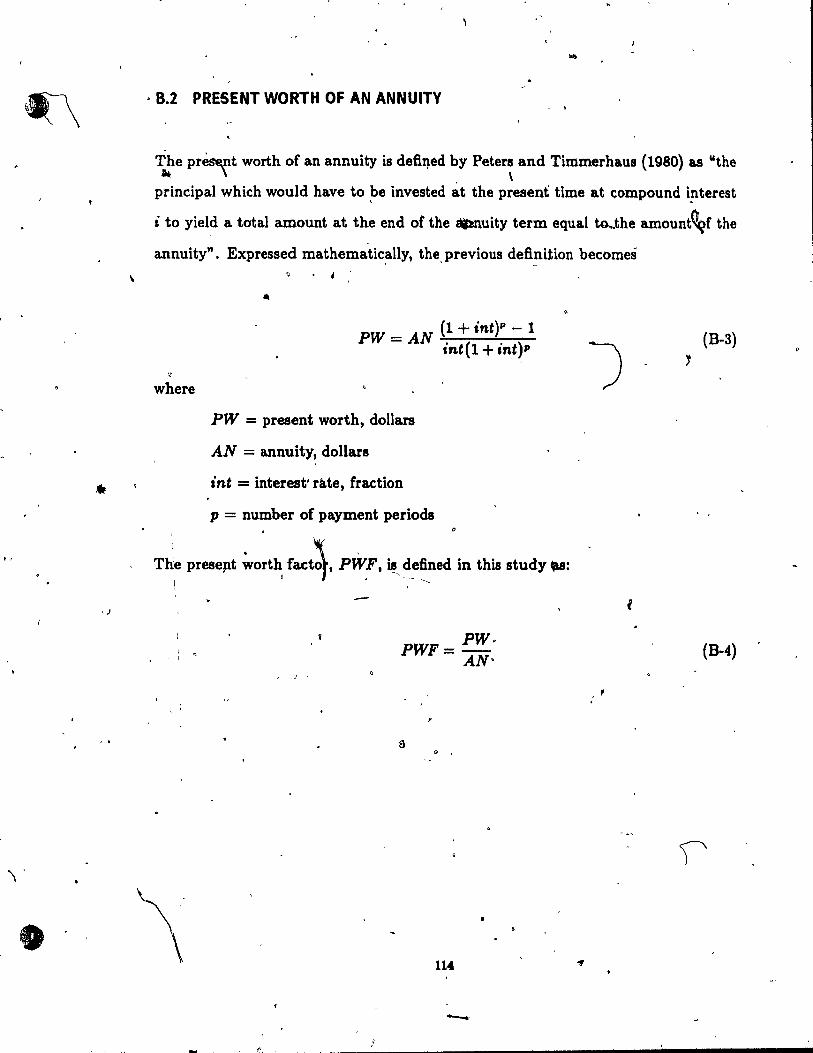
\
•
, .
, 8.2 PRESENT WORTH OF AN ANNUITY
The prè~nt worth of an annuity is defi~éd by Petera and Timmerhaus (1980) as "the - \ \ principal which would have to ~e invested àt the present time at compound Î!lterest
i to yiel~ a total amount at the end of the 8Itnuity term equal tG...the amountC!çf the
annuity". Expressed mathematically, the previous definition becomes .' -
where
PW = AN (1 + int)p - 1 intel + int)p
PW = present worth, dollars
AN = annuity, dollars
int = interest' râ.te, fraction
p = number of payment periods D
TJ. preseJlt ~o~~ fac~. PWF. is, ~eflned in this atudy ., 1 •
l ' 1
1 '. 1
• J
\
PWF= PW· AN-
,
114
-
(B-3)
(B-4)
,
.,

1
, (
APPENDIX C / COST EQUAT,IONS FO~ ÙNIT PROCESSES
Almost ail of the followinl equations were presented by Craig et cd. (1978). The
_source of the colJt fiiformation iithe study published by Patterson'and Banker (1971).
The 'equations for the aere.tion'system (diffused D:.ir), not presented by Craig et al.,
we~e obtained 'by the author. A power-type equation w~ fitted to the data using
linear regr~8ion.
The capital and O&M costs are estimated at their ~res~nt value by inc1uding the
appropriate cost index ratios in the èorresponding equations.
C.l CAPITAL COSTS
~ The coat informati~n used herein corr~ponds to January 1971. Thus, the present
\ #
value of the capital cost of each of the unit processes is calculated by multiplying the
capital c~t at January 1971 ~Y tfoat index .ratio fO)' ~Datruction. The ":,,ulting
equations are: - . . 115

'-
r
, 1
Settling tank and gravit y thiçkener,
"'where
cc = present capital <:ost, thousands of U.S. dollars
•
(C-1)
A = area of settling tank or gravit y thickener, thou8&l\ds of square feet l ' ," 100,,,-' = cost index ratio for construction
Aeration tank . ..
" . ' ....
~ , "
.\
(C-2)
Vr = volùme of activated sludge a:eration tank, millions of gallons (U.S.) ,
Aeration system (.-diffused air). ,
... ' , CC = 73 po.e'J X Icon ••
where \ :F = firm. blowe~ capacity, thousands of SCFM
Recirculàtion pllmps.
(C-4) ...
116

,. , tI
'.
, \
"" " .
'Were
q = initial firm pump~ng capacity, MGD (U.S.)
J
Sludge pumPeh
cc = 4.5 WO.63 X Icorut
where \ 0
w ;::: initial firm pumping capacity, gallons (U.S.) per minute
~nae[obiç dimter. ,.
1
OC = 300 Vell" 0.60 X Icond .. , l' .,
~where
Veli" = digester volume, millions of gallons (U.S.)
Vacuum fil\er. "
Id
qc = 5.4 A./ O•71
X Icor ....
where .~.
Â. '- = 'iilter area, square feet
117
(C-6)
, (C .. 7)
,

o
. - . \ , .. ..
. ~
/
C.~ OPERATION AND MAINTENANCE COSTS c , " - . J The,present O&M costs for e·ach of the 'fnit processes a.re ca.lculated as the suro of .
'four terms: operation costs f , maintenance costs, power costs, and material costs. The . '
tirst three terms are based on unit' w'aies an'd powe~ costs. 'lie cOsts of- materials f '
have to be corrected to pr.,esent ~ime by mUltiPl~ them b! a cost index ratio: for
materia.ls. The following expresl!lions result: - '1
Settling tank and gravit y thickener. ,
o J For A >3.0
For A < 3.0
where
00 = 360 W AO.30 -+ 270 ' Ao,Te + 200 w: AO. u op Imat ,_ ma
1 ~
l '
oc = present annua.l O&M costs, thousands of jl.S. dollars
~ WJp = present operation wages, U.S. dollars. per hour' . Ob
Wma = present maintenancè wages, U'~f' dollars per hour
/mot = cost index ratio for. materials
Aera.tion system (diff'used air) ..
~or F ~ a,.o \ . ,
(C-8.1)
(C .. 8.2)
OC = 740 WoP ?J'u +390 Wmo r·u :+2.0 ima? QoO.4' + 1.86 O2,1'0'1'' p~ ,(C-o.1) ,
$. 11S - -.
,

I~ 1
1
1
) -'
For F < 3.0 ,
OC ~ 960 W •• P"" + 460 W m. P"" + 2.0 ~m ""Qo o.,; + 1.~ 0,(1' 0 T p,. (C-9.2)
\ where
Qo = infioW rate ta. the plant, MGD (U.S.)
.. O2 .7''07'' = total oxygen requirements, Ibid
1.. Pc = present power costs, cents (U.S.) per kilowatt-h~
Recycle pymps.
,For q ~ 10.0
For 4.0 ~ q <: 10.0
OC"= (21 q+390) W •• +(15q+370) Wm • +220 fm:';~ + 1150;: q H, (C-IO.'.!)
For 1.0 ~ q < 4.0
. . OC' (21 ) w: ( ) w. '0 62 1150 Pc' q Hl ( ) = q+390 0" + 15 9,+310 ma :-350 fm~t q'.+ El' C-I0.3
,
For q < 1.0 o
where
Hl = pumping head for the recycle line, feet
El = PUmp~ efficiency for the recirculating sJudge, percentage . , ,
,.
119

•
\
•
, " "
Sludge pumœ .
- ;C = 14~ W wo. u + 59 W. wo.u + 8~ j,' wo.u + 1,656 Po 'w H 2 (0-11) 't. ()p ma ma' E' \ ~ \1'
wlJere
HI! = pumping head for the sludge system, feet
E'J = pJlmping efficiency for the sludge system, percent age \
AnaerCltbic digester, f
Oost of labor:
For Veli" ~ 1.5 ..
..
.. \ i '.
OC. a = 1200 W();Veli" o.as + 710 Wma Vd~" 0.82 , For 0.52 ~ Vd~" < 1.5
-- ~.
t'
OC. 4 = 1300 W()P Veli" 0.65 '+ 790 W ma Vdi" 0.6& '. ,
.1
For Veli" < 0-.52
where Cl
OC •• = coets of labor, thousanda of U.S~ dollans 'tt .t _ 1
Cost of materiala:
120 \~
1 \ ~
(C-12.1)
(C~12.2)
(C-12.3)
1 •
\
" .

"
J
1
•
/
.'. . . ..... 1. .~. For Vdlg ~ 0.75
, ..... , - OCm 0 = 3300 Vdig o.ee (C-12.4),.
-(
For Vdig • < 0.75 " <-
~ , .. (C-12.5)
• o
,
where . _ • ri,
odmo ;:: ~08tS of materillS', thous~ of u:s. d~tlars . .
~coo~: -,
oc = 00"114 +OOmo (C-12.6)
vacuym tilt§r.
For S ~ 10.0 <'v
OC = 3.6 WOP So.18-+ 0.83 ~m .. So ... ~ 1000 /:"ot (0.046 SO.11 + 0.026'·S'6:i{r .
,ç (C-13.1)
For 5.0 < S < 10.0 • (
~ 0
OC = 13 Wo~ 8°·12 + 0.83 Wm .. SO'u + 1000 /", .. t (0.046 SO •. 11 + 0.026 8°.16)
~ <4. t·. ' • oc;, '. -
~i' '(C-13.2) -. --For·3.0 < S < 5.0
~ l '
• OC= ~3 W., 8"' TI +~,8 Mf-. 8"'.' +1000 1 ••• (O,~ S:' Tl +~'~ 8"",') (C-13.3) 1 , 1
.. 1" _,
-"-\,I o , ~
For 1.0 < S_.< 3.0 1
• ~ 1 0
\
'. - ....-

J',
J 'r--
• FQr S < 1.0 - ., ~
B OC = 62 H;'oP 8°·53+14 Wmei 8°·4&+1000 fma. (0.046 So.Tl +0.026 8°·10) (C-13.5)
') wh~re
8 = Bolids 6,ltration raie, tons {U.S.) per year , --
"
1
C.3 ADDITIONAl EXPENDITURES
,
The equations that 'allow the computation of the additional expenditures includ~d - . ,
in the initi~l inyestment were taken from the wor~ by Smith (1969). -Thoae- coat .. ,
functions are: f ~
, s.iP J
Il
1 \-
1 Profit for contractor. ,1 ... .
CCPO ;:::: 0.10 CC'(OT
where -
CCpo -: profit for contractor, thowsan~ of U.S-, d,oHan
cap al ~OfIt, thousanda of U.S. dollare ,
\ C t' ". d .. ~ on 1I1Iencles an om1S810
, ,(! • 0
: "(C-15) ~
• ~ .
where a J ; . ~ "
, . ' " 'CCdô ~DtÏDI~c:it!l'and omiuions, thousands of U.S •. dollan)' . \. , . "---- -
\ ~ H2 10( , . .

'1
. ~
l ~
0
\ \
o
çost of Engineering.
where •
cc. = cost of engineéring, thousands oru.s. dollars o
Cost of land.
cc, = 0.02 CCTOT
where
cc, = coat <if land, thousands of U.S. dollars
, ,
"
..
123 0,
1 .. PJ
(C-16)
ù
(C-17)
"
/
. "
1

-------------.--- ------
o
1. ,
APPENDIX 0
PIf0 9 RAlYI OUTPUT
• <.
The complete output of ih~ program itshown in the Unes below. It corresponds to
the output of Example No. 4.
, , o
program: STEPF
DESIGN INPUT DATA:
STAGES - 4
Qo - 50000.00 So ..
cu .. m./d mg BOD/L mg BOD/L BOOTe -
Xe -VSS/SS -
400.0 30.0 30.0 .7'50
mg SS/L (upper .bound)
BIOKINÈTIC CONSTANTS: . yt - .600 mg VSs/mg BOO Kd - .040 l/d K ,- .030 L/mg d
FLOW COEFFICIENTS: Alpha (1) - .250 Alpha (2) - .250 Alpha (3) - .250 Alpha (4) - .250
Settlinq'velocity coett. -settli~q exponent -
1
, 15.000 ClD/min, .60000 L/q .
,
III
Amortization period (y.ars) - 20 , Interest rate ct) - 9.00 currency Exchange • 1. 300 CANSjUS$ /" •
R (optimum) .- .2100 --x.:(~t~ - 210~.OO
,
\''\
. (
(

DES~GN PARAMETERS:
AERATION TANK: ~
24174.~4 cu.m. 5.40 d
TOTAL VOLUME -SSRT -BSRT (Xllin) - .14 d
âXÔMASS DISTRIBUTION
X(1) -X(2} • X(3} • X(4) -
Xa • Xr •
3237.28 mg VSS/L 2163.19 mg VSS/L 1650. 06 mg VSS/L 1349.47 XIIg VSS/L
2100.00 7775.52
mg VSS/L mg VSS/L'
Soluble BODInsoluble BOO -Tota! BOO-
t18.84 ~g/L 11.15 mg/L 30'.00 mq/L
SLUDGE PRODUCTION/STAGE
Sludge(l) - r 2468.16 Kg VSS/d Sludge(2) - 2351.14 Kg VSS/d Sludge (3) - 2309.50 Kg VSS/d Sludga (4) - 2275.19 Kg VSs/a.
SUBSTRATE DISTRIBU1ION
S (1) -S(2) = S (3) = S(4) -
8.5218 .mg BOD/L 12.1~85 mg BOD/L 15.6444 '1IIg BOD/L 18.8449 mg BOD/L
OXYGEN REQUIREMENTS/STAGE
02req(1) • 3998.02 Kg/d 02req(2) .. 3808.48 Kg/d' 02req(3} - 3741:02 Kg/d 02req(4) .- 3685.45 Kg/d
TOTAL SLUOGE PROD. - 9403-.98 Kg VSS/d ~
TOT~LUDGE FLOW - 1119.77 cu.m./d (from recycle line) TOTAL XYG~N REQ. - 15232.98 Kg/d
- SETTLING TANK:
Area ORA u GL Xe XL
- 1761.48 sq.m. (thickeninq gover~s) 1.97 cm/min -- .41 cm/min --• 61.80 Kg/sq.m. d
18.59 mg SS/L ) . 8280.71 mg SS/L 1 (
TREATMENT PLANT DESIGN"""
Act.Slud. tank volume -Aeration system dapacity -secon~ary claritier area -Recirc. pumps capacity' -Sludge pumps capacity -Thickener area -Anaerobie digastar volume • Vacuum tiltar area •
(
29009.56 31735.40
3522.95 21000.00 1555~24 361.14
26092.04 17.51
. " . .
125 .~
CU.XII. cu.m./hr ,
sq.m. cu.m./d L/min sq.m. cU.m. sq.m •
'-
e ( ( ( ( ( ( (
, '.
SF .. 1. 20 )
SF - 1.50 J SF - 2.00 ) SF - 2. 00 ) SF • 21('00 ) SF - 1. 50 ) SF - 2. 00 ) SF - 1. 00 )
,
"
(,

-\
-B
)
•
"
)
CAPITAL COST FOR THE TREATMENT PLAN'!': .. (in CAN $) ,.
const~c7ion index - 2.9940
Coat çf act. slud. tank - $ 2643986.32 Coat ot aeration system • $ 1744832.68 Coat of secondary clarifier • $ 1727005.53 Coat of .J'Scirc. pumps - $ 241274.55 Coat ot sludge pumpa • $ 425265.93 Coat of thickener • $ 298942.54 Cost of anaar. digester - $- 3647283.57-Coat ot vacuum .til ter • $ 866999.98
Sub-total capital co st - $ 11595591.'09
" Profit for contractor - ~( 1159559.1l
Contingencj,§Ul.. and omissions - 1739338.66 Cost of enqineering - \ 648306.55 Co st ot land - $ 231911.82
Plant> total capital cost - $ 15374707.23
~ YEARLY O&M COST FOR THE
(in CAN $) TREATMENT PLANT:
index - 3.0050
O&M of aeration system - $ 809587.50 O&M 0 secondary clarifier - $ 66579.83 O&M o recir~ump. .... $ 58791.03 O&M f slud9'fl' wnps • $ 53964 .~3 O~M t thick er . • $ . 15673. 0 O&M of anaer. diqester • $ i78593.60 O&M qf vacuum rilter • $ 264689.40
Total O&M co st (par y,ar) j' $, 1447880.00
""1-
TOTAL PRESE~.WORTH OF PLAN • $ 2859'1741.23 (in CAN $)
~I
" 0,
/ , .
! \
...
1 -
C P
" ,
')

....... '(
)
l
.'
REFERENCES
Agnew, R.W., "A mathematical model of a final clarifier", U .S. EPA, Water Pollution Control ~search Series, Project 17090 F JW, February 1972.
, Andrews, J.F., "Dynamic Models and Control Strategies (or WasteW'ater Treatment Processes", Wate", RtSMrch, Vol. 8, 1974, pp. 261-289.
Arceivala, S;;1., "Wastewater Treatment and DisposaI", Marcel Dekker, Inc., New -York, 1981. \' •
Benefleld, L.D. and~Randall, C.W., "Biological Process Design for Wastewater Treatment" , Teleprint Publishing, Virginia, 1980.
Biospherics, Ine., "Biomass Determination - A New Technique for Activated Sludge Control", Water Pollution Control Research Series 17050 EOY 01/72, U.S. Environ-
/ mental Protection Agency, Washington, D.C., 1972.
Bjsogni, J., Jr. and Lawrence, A.W., "Relationships between Biological Solids Retention Time and Settling CharacteristÎcs of Activated Sludge", Water Research, Vol. 5, 1971, pp. 753-763. '"
Buhr, H.O., Goddard, M.F., Wilson, T.E. and Ambrose, W.A., "Making Full Use . , of ~tep Feed Capability", Jour. Water Pollut. Control Fed., Vol. 56, No. 4, 1984, pp. 325-330.
Buhr, H.O., "Solida Distribution in a Step Feed Plant", internaI ReFr\ Greeley and"" Hansen, Phoenix, Ariz., 1982. ' ,
Busby, J.B. and Anàiews, J.F., "Dynamie Modeling and Control Strategies for the Aetivated Sludge Pracess", Jour. Water Pollut. Control Fed., Vol. 47, No. 5, 1975, pp. 105~-1080.
Chapman, D.T., "The influence of pracess variaJ?les on,secondary clarification", Jour. Water Pollut. Control Fui., Vol. 55, No. 12, December 1983, pp. 1425-1434.
1 •
Conimittee on Water Pollution Manag~ment of the Env. Eng. Div., "Engineering design variables for the a.ctivated sludge p~ocess" , Jour. En"ironmental Eng. Division, ,ASOE, Vol. 106, June 1980, pp. 473-503. "
Craig, E.W., Meredith, D.D. and Middleton, A.C., "AIgor~m for optimal1activated sludge design", Jour. Enuironmental Eng. Dim'sion, ABeE, Vol. 104, Decemkr 1978, pp. 1101-,1117.
Oullinane, M.J., "Computer-based wastewater manâgement C08t estimating techniques - the second generation", Environmental Laboratory, U.S . .Arrily Engineer Waterways Experiment Stationt April 1979.
1 •
Dames && Moore, "Construction Costs for Municipal Wastewater Treatment Plants: 1973-1977", Technical Report, U.S. EPA 430/9-77-01${1978a .
.. 127 ..

------------------------~----- -y-- -
o
1.
Dames F:, Moore, "Analysis of Operations and Ma1ntenanc~ Costa for Municipal 'Waste~ Treatment' Plants", TeclÙlical Report, U.S. EPA 430/9-77-915, 1978b.
Deaner, D.G. and Martinson, ,S. "Communication: Definition and Calculation of Mean Cell 'Residence Time", Jour. Water Pol/ut. Control Fed., Vol. 46, No. 10, October 1974, pp. 2422-2424.
Dick, R.I., "Role of Activate~udge Final Settling Tanks", Jour. Sanitarll Eng. Division, ASeE, Vol~ 96, SA2, AP~ 1970, pp. 423-436.
Dic~, R.I., "Folklore in the Design of Final Settling Tanks", Jour. 1ater Pol/ut. Control Fed., Vol. 48, No. 4, 1976, pp. 633-644.
Dick, R.I., and Javaheri, A.R., Discussion of "Unified Hasis for Biological Treatment .Design and operation", Jour. Sanitarll Eng. Division, ASCE, Vol. 97, SA2, April 1971, pp. 234-238.
Dick, J.1. and Suidan, M.T., "Mod~ling and Simulation of Clarification and Thickening Pr~esses", In MathemaUcal Modeling f~r Water Pollution Contr~l- Processes by T.M. Kèinath and M.P. Wanielista~ Eds., Ann Arbfr S~ie;nce, 1075, pp. 147 .... 191.
Dick, R.1. and Young, K. W., "Analysis of Thickenin~ Performance of Final Settling Tanks", l!7th lndustrial Waste Conference, Purdue Univ., May 1972, Part 1, pp. 33-54.
Dix, H.M., "Environmental Pollution", John Wiley & Sons, New York, 1981. > -
Eekenfelder, W.W. Jr., "Comparative biological waste treatment design", Jour. Sanitary Eng. Division, ASCE, Vol. 93, SA6, December 1967, pp. 157a-;170 .
• ' Edwards, G.P., "Discussion - Factors Affecting the Efficiency of Activated Sludge Plants", Sewage Warka Journal, Vol. 21, 1949, pp. 640. '
Engineering News-Record, Vol. 186, No. 2, January 14, 1971-
ENR, Vol. 218, No. 24, June 11, 1987.
Erickson, L.E., Ho, Y.S .• and Fan, L.T., "Modeling and Optimization of Step Aeration Waste Treatment Systems", Jour. Water Pollut. Control Fed., Vol. 40, No. 5, May lofH>8a, pp. 717-732. ()
Erickson, ~~~' Chen, G.K.C. and Fan, L.T., "Modeling and Optimization of Biological Waste 'atment Systems", Water - Chemical Engineering Progrell SJlmpolium
\
Series, Vol. , No. 90, 1968b, pp. 97-110. . ,
Ganezarezyk, J.J., "Activated Sludge Pracess: Theory and Practice", Marcel Dekker, Ine., New York, 1983.
Garret, M.T. and Sawyer, C.N., "Kineticl of Removal of Soluble BOD by Activated Sludge", Proceeding. olthe'7th lndustrial -WBlte Conference, Purdué Uniuer.itll, 1951, pp. 51-77.
128 \
("

t
'", ,
Ghobrial, F .~., "Importance of the c~arificati~ phase in biOlogiC~l process control", Water Re8ta~ch, Vol. 12, 1978, pp.J009-1016.
1 Gould, R.H., ,"Tallman's Island Works Opens for World's Fait", Municipal Sanitation, Vol. 10, No. 4, 1939, pp. 185.
Gould, R.H., "Sewage Aeration Practice in New York City", 'Proceedings ASCE, Paper 307, Vol. 79, October 1953, pp. 307-1-307-11>1-
,
Grady, C.P.L. Jr., "Sirnplified op~imization of activated sludge process" , Jour. Environmental Eng: Divi8ion, ASCE,'Vol. 103, June 1977, pp. 413-429. J/lJ Hillier, F.S. and Lieberman, G.J., "Introduction to Operations Research", 4th Ed., Holden-Day, Ine., 1986.
Irvine, R.L. and Busch, W.,' "Sequ~ncing Batch Biological Reactors - An Overview"j Jour. Wattr PC?l.lut. Control Fed., Vol. 51, No. 2, 1979, pp. 235-243.
-Jenkin~, D. and Garrison, W.E., "Control of activated sludge by mean cell reâidence time", 'Jour. Water Pollvt:" Control Fed., Vol. 40, No. 11, Part 1, November 1968, pp. 1905-1919. 1
A Joint Committee·èf the Water Pollut. Control Fed. and the ASCE, ""Wastewater Treatment Plant Design", Washington D.C.,,1977. )
. Jones, W.L. and Schroeder, E.D., "Discussion of: Making,Full Use of Step Feed Capability", by H.O. Buhl; et al., Jour. Wattr Pollut. Cl3ntrol Fed., Vol. 57, No. 9, 1985, pp. 974-975.
Keinath, T.M., Ryckman, M.D., D~a, C.H. and Horer, D.A., "Aetivated SludgeUnified System Design and Operation", ABCE Proceuling8, Vol. 103, No. EE1-6, 1977, pp. 82~849 .
. Keinath, T.M., "Operational Dynamics ~d Control of Secpndary Clarifiers", Jour. Water Pollut. Cqntrol Fed., Vol. 57~o. 7, July 1985, pp. 770-776.
'\ Ketchum, L.H. Jr., Irvine, R.L. and Liao, P., "First coat analysis of sequencing batch biological reactors", Jour. Wattr Pollut. Control Fed., Vol. 51, No. 2, February 1979,
/ pp. 288-297.
Lawree.' W.L. and McCarty, P.L., "Unified Basié for-'Biological Treatment Design and O~tion", Jour. Sanitary Eng. Divi8ion, ASqE, Vol. 96, 1970, pp. 757-778.
1 Lawrence, W.L. and Milnes, T .Jt., "Role of Activated Siudge Final Settling Tanks '(Discussion by)", Jour. Sanitary Eng. Divi8ion, ASCE, Vol. 97, 1971, pp. 121-123.
MeHarg, W.H., "Designing the Optimu~ S~tem for Biological-Waste-Treatment", Ohemical Engineer.'ng, Vol. 80, December 24 1973, pp. 46-49.
,. ,
MeKee, J.E., and Fair, G.M., "Load Distribution in the Activated Slud.ge Process", SeVHJge Work.t Journal, Vol.. 14, No. 1, 1942, pp. 121. '
129

•
Metcalf'" Eddy,. 'Wastewater Engineerin~: Treatment, Disposai, Reus ( , 2nd 'Ed., McG~w-Hill, New York, 1979. :J' Middleton, A.C. and Lawrence, A.W., "Coat Optimization of Activated Sludge Systems", Biotechnology and Bioengineering, Vol. 16, 1974, pp. 807-826.
Milbury, W.F., Pipes, W.O. and Grieves, R.B., "Compartmentalization of aeration tanks", Jour. Sanitary Eng. Division, ASeE, Vol. 91, June 1965, pp. 45-61.
. Miyaji, Y. et al; "Biological Nitrogen Removal by Step-Feed Process", Prog. Water Technol. (G.B.) Vol. 12, 1980, pp. 193.
Monod, J., "The Growth of Bacterial Cultures", Annual Review of Mierobiology, Vol. 3, 1949, pp. 371-394.
Mynhier, M.D. and Grady, C.P.L~, Jr., "Design Graphs for Activated Sludge Pracess", Jour. Environmental Eng. Division, ASOE, Vol. 101, 1975, pp. 82g.....846.
· Niku, S. . 4d Schroeder, E.n., "Stability o( ActivkÎed Sludge Pracesses based on Statistical easures", Jour. Water Pollut. Oont;';';F~d., Vol. 53, No. 4, April 1981, pp. 45?~7 . ~-<.,. Niku" S. S oeder, E.D. and Haugh, R.S., "Reliability and Stability of Trickling Filter P oc " Jour. Water Poli ut. Oontrol Fed., Vol. 54, No. 2, February 1982, pp. 129-134. -. "
Nowak, G., Brown, G. and Yee, A., "Eff'ects of feed pattern and dissolved oxygen on , growth of filamentous bacteria", Jour. Water Pollut. Control' Fui., Vol. '58, No. 10, October 1986, pp. 978-984. '
Ong, S.L. and Lee, G.S., ~Optimizing the Design of an Activated SludgejSecondary Clarifier System via Univariate Search Technique", Water, Air and Soil Pollution, Vol. 34, No. 1, 1987, pp. 1-9.
Parkin, G.F. and Dague, R.R., "Optimal Design of Wastewater Treatment Systems by Enumeration", Jour. San#o.rfl Eng. Division, ABOE, December 1972, SA6, pp. 833-851.
Patterson, J.W 0' Brezonik, P.L. and Putnam, H.D., "Meuurement and Significance of Adenosine Triphœphate in' Activated Sludge" , Environmento.l Seienee Fi Ttchnologu, Vol. 4, No. 7, July 1970, pp. 569-575. '
Patteraon, W.L. and Banker, R.F., "Estimating Costs and Manpower Requirements for Conventional Wastewater Treatment Facilities", Water Pollution Control Res. Sere 17090 DAN 10/71, U.S. EPA, 1971.
Peavy B.S., Rowe, n.R. and Tchobanogloua, G., "Envil'Onmental E • Il Mc-Graw Hill, New York, 1985.
Petera, M.S. and Timmerhaus, K.D., "Plant Design an onomies for Chemical Engineers",3rd Ed., McGraw-Hill, New Yo
...d- . '
\

L
r
\
)
Pftanz, P., "Performance of iActivated Sl~dge) Secondary Sedime~tation Basins", Proceedings of the .4th International Conf., International Assoc. on Water Pollut. Research, Praguè, 1969, pp. 569-581.
\ '
Poloncsik, S., Grieves, R.B. and Pipes, W.O., Jr., "Process Optima in Activated Sludge", ProceedingB of the eOth InduBtrial Waste Conference, Purdue University, May 1965, pp. 197-209.
Riddell, M., Lee, J. and Wilson, T., "Method for estimating the capacity of an activated sludge plant", Jour. Water Pollut. Control Fed., Vol. .55, No. 4, April 1983, pp. 360-368. ~
Rossman, L.A., "Synthesis of waste treatment systems by implicit e~umeratl\lJl(l"" Jour. Water Pol/ut. Con.trol Fed.I.Vol. 52, No. 1, January 1980, pp. 148-160.
Smith, R. "Cost of conventional and advanced treatment of wastewater" ,Jour. Wattr Pollut. Control Fed' j Vol. 40, No. 9, September 1968, pp. 1546-1574.
, Smith, R., "Preliminary design 'of wastewater treatment systems", Jour. Sanitary Eng. Division, ASCE, Vol. 9~ebruary 1969, pp. 117-145.
S~rensen, P.E., "Èvaluat.ion or-dperational Benefits to the Activated Sludge Proce8s Using Step Feed Control Strate2i ", Prog. Water Technology, Vol. 12,1980, pp. 109.
St6rensen, P.E., "Modelling of E ent Quality Control for Activated Siudge Plants", in Mathematical Models in ological Waste Water Treatment, Elsevier, 1985, pp. 133-146. '
Spaine,,,P.A. and Walski, T.M., "Problems in performing cast analyses for facility planning", ASCE Environmental Eng. Conference, Nashville, TN, July 1977.
StaIl, T.R. and Sherrard, J.H., "Evaluation of Control Parameters for the Activated Siudge Pracess", Jour. Water Pol/ut. Control Fed., Vol. 50, No. 3, 197~, pp. 450-457 .
. Stenatrom, M.K. and Andrews, J.F., "Real-Time Co trolof tivated Sludge Process". Jour. Environmental Eng. Division, ASCE, Vol. 05, A il 1979, pp. 245-260.
Stenstrom, M.K. and Andrews, J.F., "Cast interaçtions in activated sludge systems" , Jour. Environmental Eng. Division, ASCE, VoY.i06, August 1980, pp. 787-796.
, Stephenson, J .P., Monaghan, ,B.A. and Yust, L.Y., "Pilot Scale Investigation of Com-puterized Control of the Activated Sludge Pracess" , Report SCAT -12, Cânada Mortgage and Housing CorporatioI}.-Environment Canada, 1982.
Suidan, M.T., Saunders, F.M., Godfrey, C.S. and Steward, H.T., "Wastewater treatment: sensitivity analysis", Jour. Environmental Eng., ASCE, Vol. 109, No. 1~ 1983,
/
pp. -120-138. .
Tang C., Downey Brill, E., Jr., an\ Pfeffner, J.T., "Optimization Techniques for Sec- ( ondary Wutewater Treatment System" , Jour. Environmental Eng., ASeE, Vol. 113, No. 5, October 1~7a, pp. 935-951. '
131
\

1
/
Tang C., Downey Brill, E., Jr., and Pfeffner, J.T., "Comprehensive Model of Activated Sludge Wastewatèr Tr~atment System" 1 Jour. Environmental Eng., ASeE, Vol. 113, No. 5, October 1987b, pp. 952-969.
Tchobanoglous, G. and Schroeder, E.D., "Water Quality: Chara.cteristics, Modeling, Modification" , Addison-Wesley, Inc., Mus., 1985.
Thompson, D., "Step Feed for Reducing the Impact of Storm Flow", Wutewater Technology Centre Newsletter, Environment Canada, No. 9, November 1987, pp. 4. . ,
Torpey, W.N., "Practical~esults of Step-Aefation", 8ewage Works Jour., Vol. 20, 1948, pp .. 781
Tyteca, D., "Nonlinea.r programming model of wastewater treatment plant", Jour. • Environmental Eng. Division, ASCE, Vol. 107, August 1981, pp: 747-766.' .
, Tyteca, D., "Mathematical Models for C08t-Effècti:ve BiologicaI Waatewater Treat-ment", in Mathematical Models in Biological 'Wa.ste!Water Treatment, Elsevier, 1985, pp. 737-802. (
t.yteca, D. and Smeers, Y., "Nonli~ear progra.mming design of wastewater treatment plant", Jour. 'Environmen.tal Eng. Division, ASCE, Vol. 107, August 1981, pp. 767-779.
Tyteca, D., Sméen, Y. and Nyna, E., "Mathema.tical Modeling and Economlc Optimization of Wa.stewàter Treatment Plants", CRC Critical ReviewI in Environmental Control, Vol. 8, No. 4, December 1977, pp. 1-89.
U.S. Army Corp of Engineers, "Computer Assisted Procedure for the Design and Evaluation of Wastewater Treatment Systems (CAPDET)", Dra!t Dept., Office of the Chief of Engineers, Corps of Engineers, Depa.rtment of the Army, 1975.
Vesilind, P.A., "Design of Prototype Thickeners from Batch Settling Tests", Water and Sewage Worka, Vol. 115, No. 7, July 1968, pp. 303-307.
Vesilind, P.A., "Treatmerlt and Disposai of wastewater sludges" , 2nd. Ed., Ann Arbor Science Publishers, Inc., Michigan, 1979. . Ween, W.A., and Andrews, J.F. f "1:he Effect of Conta.cting Patterns on the Transient Response of Activated Sludge Systems", 47th Ann. Conf. Water Pollut. Control Fed., Denver, CoL, October 1974. ~
• A
Wehner, J.F~, and Wilhelm, R~F. ~oundary Conditions of Flow Reactor", Chemical Engineering Science, Vol. 6, 1 8, pp. 89.
J V --
) West, A.W., "Operational Control Procedures for the Activated Sludge Proces., Part m-B, Calculation Procedures for Step-Feed Process Responsee", Report No. PB-258-268, Prep~ed for U.S. EPA, Washington, D.C., 1075.
Wilber, C. m, Martin, R.F., Kra.snoff, P.J. and Donnellon, J.J., "Step Aeration Design", 53rd Annual Water Pollut. Control Fed. Conference, Las Vegas, Nevada, September 28-0ctober 3, 1980. J '
132
/
'4

........ 1
, "
- - 1
Wilson, T.E. and Lee, J.S., "A COD;.lparison of Final Clarifier Design Techniques"'; p~oé. of,the Research Symp08ia 53rd Annual Water Pollut. Control Fed. Confez:ence" ,Las Yegas, Nevada, 1980, pp. 1-12. '
u
Yust, 'L.J., Stephenson; J .P, and Murphy, K.L., "Dynamic Step Feed Control for Organic Carbon Removal,in a SU8pe~~ed Growth System"" Water Scie~ce and Tech-n%gy, Vol. 13, 1981, pp. )'29-736. " , -.
, ('
\
, '-
--- l
183
, -'