- sfi system sfi system - ラバーメイド セミライブ …97supraturbo.com/1997 service...
TRANSCRIPT
SF0GG-01
-SFI (2JZ-GTE) SFI SYSTEMSF-1
1327Author: Date:
1997 SUPRA (RM502U)
SFI SYSTEMPRECAUTION1. BEFORE WORKING ON FUEL SYSTEM, DISCON-
NECT NEGATIVE (-) TERMINAL CABLE FROM BAT-TERY.
HINT:Any diagnostic trouble code retained by the computer will beerased when the negative (-) terminal cable is removed fromthe battery.Therefore, if necessary, read the diagnosis before removing theterminal.2. DO NOT SMOKE OR WORK NEAR AN OPEN FLAME
WHEN WORKING ON FUEL SYSTEM.3. KEEP GASOLINE AWAY FROM RUBBER OR LEATH-
ER PARTS.4. MAINTENANCE PRECAUTIONS(a) In event of engine misfire, following precautions should
be taken.(1) Check proper connection of battery terminals, etc.(2) After repair work, check that the ignition coil termi-
nals and all other ignition system lines are recon-nected securely.
(3) When cleaning the engine compartment, be espe-cially careful to protect the electrical system fromwater.
(b) Precautions when handling oxygen sensor.(1) Do not allow oxygen sensor to drop or hit against an
object.(2) Do not allow the sensor to come into contact with
water.5. IF VEHICLE IS EQUIPPED WITH MOBILE RADIO SYS-
TEM (HAM, CB, ETC)If the vehicle is equipped with a mobile communication system,refer to the precaution in the IN section.6. AIR INDUCTION SYSTEM(a) Separation of the engine oil dipstick, oil filler cap, PCV
hose, etc. may cause the engine to run out of tune.(b) Disconnection, looseness or cracks in the parts of the air
induction system between the throttle body and cylinderhead will allow air suction and cause the engine to run outof tune.
7. ELECTRONIC CONTROL SYSTEM(a) Before removing SFI wiring connectors, terminals, etc.,
first disconnect the power by either turning the ignitionswitch OFF or disconnecting the negative (-) terminalcable from the battery.
HINT:Always check the diagnostic trouble code before disconnectingthe negative (-) terminal cable from the battery.
P03244
LockPress Down
P03245
Lock
Insert
P13048
SST
P12072
Fuel PumpConnector
SF-2-SFI (2JZ-GTE) SFI SYSTEM
1328Author: Date:
1997 SUPRA (RM502U)
(b) When installing the battery, be especially careful not to in-correctly connect the positive (+) and negative (-) cables.
(c) Do not permit parts to receive a severe impact during re-moval or installation. Handle all SFI parts carefully, espe-cially the ECM.
(d) Do not be careless during troubleshooting as there arenumerous transistor circuits and even slight terminal con-tact can further troubles.
(e) Do not open the ECM cover.(f) When inspecting during rainy weather, take care to pre-
vent entry of water. Also, when washing the enginecompartment, prevent water from getting on the SFI partsand wiring connectors.
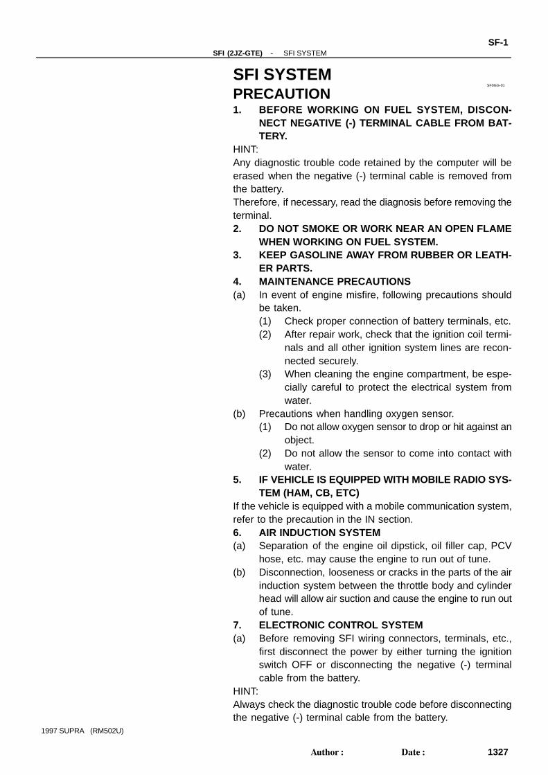
(g) Parts should be replaced as an assembly.(h) Care is required when pulling out and inserting wiring con-
nectors.(1) Release the lock and pull out the connector, pulling
on the connectors.(2) Fully insert the connector and check that it is locked.
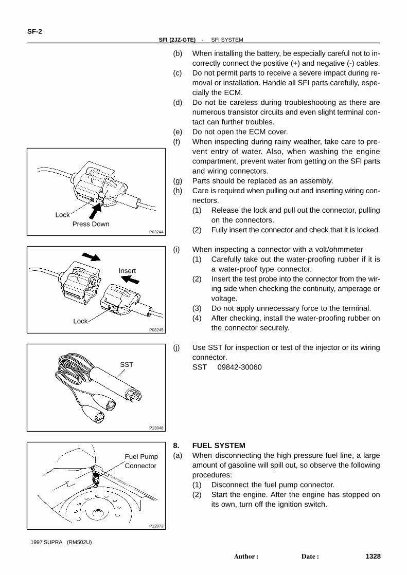
(i) When inspecting a connector with a volt/ohmmeter(1) Carefully take out the water-proofing rubber if it is
a water-proof type connector.(2) Insert the test probe into the connector from the wir-
ing side when checking the continuity, amperage orvoltage.
(3) Do not apply unnecessary force to the terminal.(4) After checking, install the water-proofing rubber on
the connector securely.
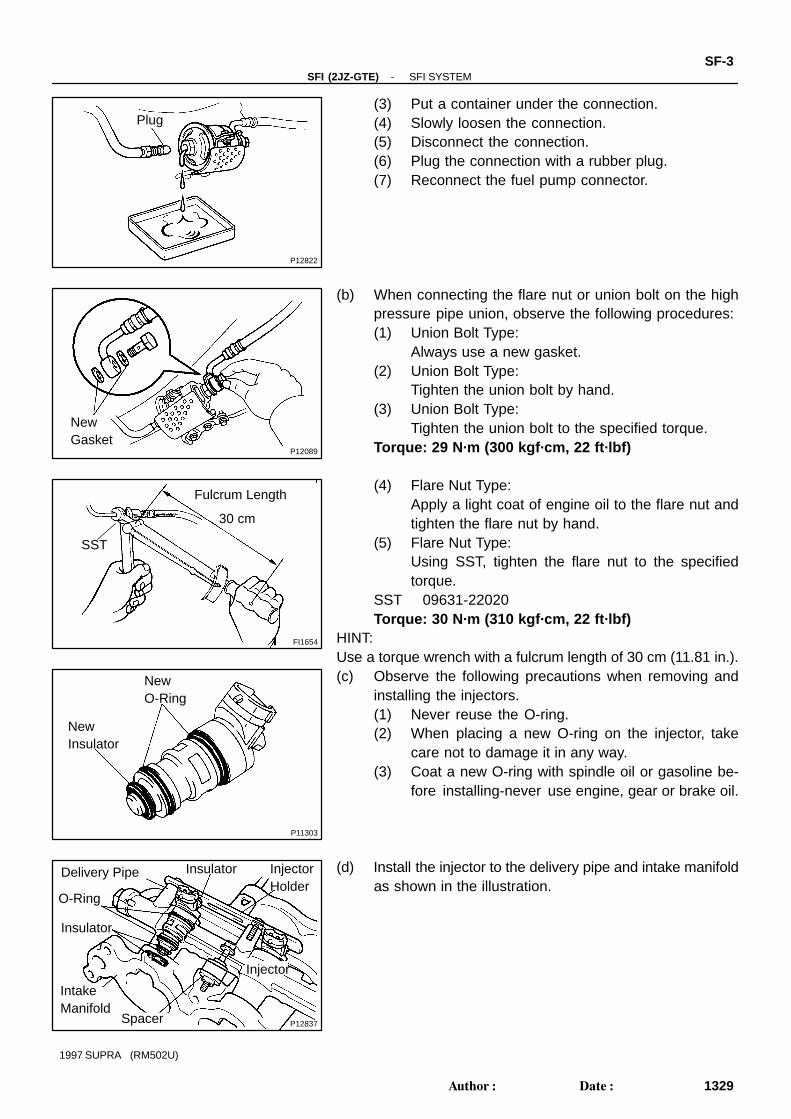
(j) Use SST for inspection or test of the injector or its wiringconnector.SST 09842-30060
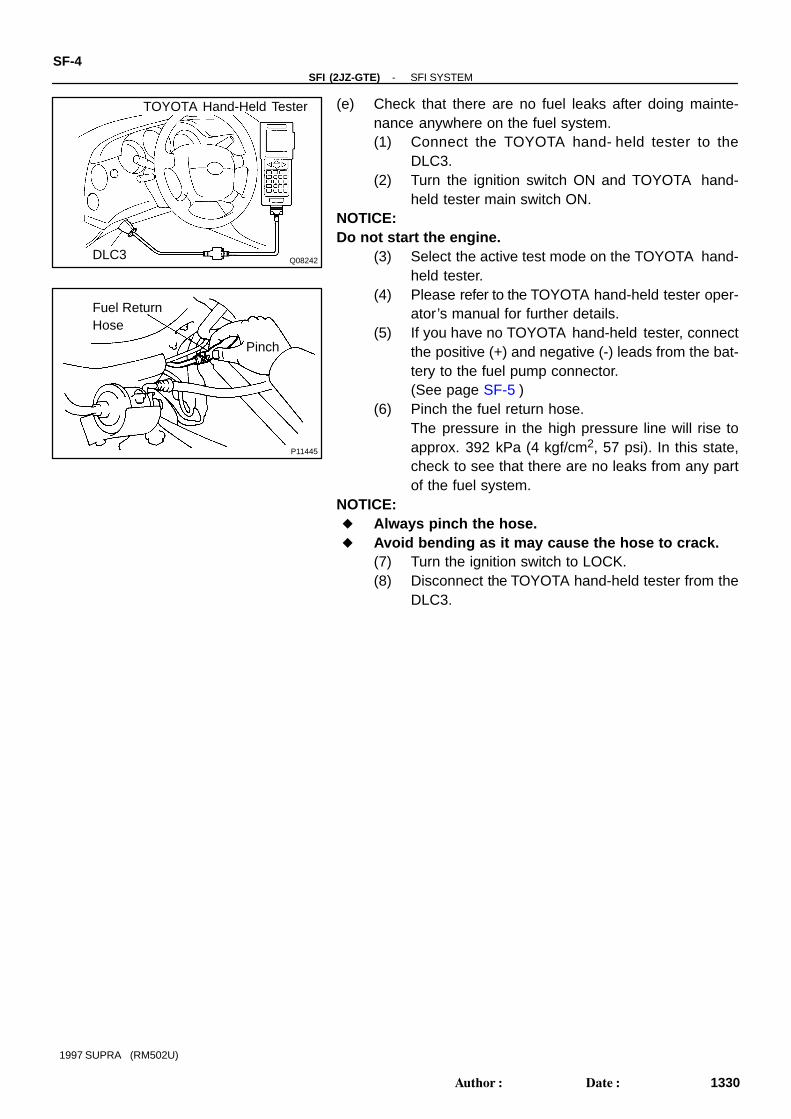
8. FUEL SYSTEM(a) When disconnecting the high pressure fuel line, a large
amount of gasoline will spill out, so observe the followingprocedures:(1) Disconnect the fuel pump connector.(2) Start the engine. After the engine has stopped on
its own, turn off the ignition switch.
P12822
Plug
P12089
NewGasket
FI1654
Fulcrum Length
30 cm
SST
P11303
NewO-Ring
NewInsulator
P12837
Delivery Pipe
O-Ring
Insulator
IntakeManifold
InjectorHolder
Injector
Spacer
Insulator
-SFI (2JZ-GTE) SFI SYSTEMSF-3
1329Author: Date:
1997 SUPRA (RM502U)
(3) Put a container under the connection.(4) Slowly loosen the connection.(5) Disconnect the connection.(6) Plug the connection with a rubber plug.(7) Reconnect the fuel pump connector.
(b) When connecting the flare nut or union bolt on the highpressure pipe union, observe the following procedures:(1) Union Bolt Type:
Always use a new gasket.(2) Union Bolt Type:
Tighten the union bolt by hand.(3) Union Bolt Type:
Tighten the union bolt to the specified torque.Torque: 29 N·m (300 kgf·cm, 22 ft·lbf)
(4) Flare Nut Type:Apply a light coat of engine oil to the flare nut andtighten the flare nut by hand.
(5) Flare Nut Type:Using SST, tighten the flare nut to the specifiedtorque.
SST 09631-22020Torque: 30 N·m (310 kgf·cm, 22 ft·lbf)
HINT:Use a torque wrench with a fulcrum length of 30 cm (11.81 in.).(c) Observe the following precautions when removing and
installing the injectors.(1) Never reuse the O-ring.(2) When placing a new O-ring on the injector, take
care not to damage it in any way.(3) Coat a new O-ring with spindle oil or gasoline be-
fore installing-never use engine, gear or brake oil.
(d) Install the injector to the delivery pipe and intake manifoldas shown in the illustration.
Q08242
TOYOTA Hand-Held Tester
DLC3
P11445
Fuel ReturnHose
Pinch
SF-4-SFI (2JZ-GTE) SFI SYSTEM
1330Author: Date:
1997 SUPRA (RM502U)
(e) Check that there are no fuel leaks after doing mainte-nance anywhere on the fuel system.(1) Connect the TOYOTA hand- held tester to the
DLC3.(2) Turn the ignition switch ON and TOYOTA hand-
held tester main switch ON.NOTICE:Do not start the engine.
(3) Select the active test mode on the TOYOTA hand-held tester.
(4) Please refer to the TOYOTA hand-held tester oper-ator’s manual for further details.
(5) If you have no TOYOTA hand-held tester, connectthe positive (+) and negative (-) leads from the bat-tery to the fuel pump connector.(See page SF-5 )
(6) Pinch the fuel return hose.The pressure in the high pressure line will rise toapprox. 392 kPa (4 kgf/cm2, 57 psi). In this state,check to see that there are no leaks from any partof the fuel system.
NOTICE: Always pinch the hose. Avoid bending as it may cause the hose to crack.
(7) Turn the ignition switch to LOCK.(8) Disconnect the TOYOTA hand-held tester from the
DLC3.
Q08242
TOYOTA Hand-Held Tester
DLC3
P11446Fuel Inlet Hose
P12558
Fuel InletHose
SF0GH-01
Z13307
Fuel Inlet Hose SST
Gasket
SST
SST
Gasket
(Union)
-SFI (2JZ-GTE) FUEL PUMPSF-5
1331Author: Date:
1997 SUPRA (RM502U)
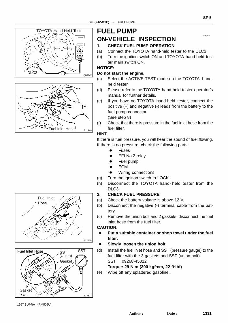
FUEL PUMPON-VEHICLE INSPECTION1. CHECK FUEL PUMP OPERATION(a) Connect the TOYOTA hand-held tester to the DLC3.(b) Turn the ignition switch ON and TOYOTA hand-held tes-
ter main switch ON.NOTICE:Do not start the engine.(c) Select the ACTIVE TEST mode on the TOYOTA hand-
held tester.(d) Please refer to the TOYOTA hand-held tester operator’s
manual for further details.(e) If you have no TOYOTA hand-held tester, connect the
positive (+) and negative (-) leads from the battery to thefuel pump connector.(See step 8)
(f) Check that there is pressure in the fuel inlet hose from thefuel filter.
HINT:If there is fuel pressure, you will hear the sound of fuel flowing.If there is no pressure, check the following parts:
Fuses EFI No.2 relay Fuel pump ECM Wiring connections
(g) Turn the ignition switch to LOCK.(h) Disconnect the TOYOTA hand- held tester from the
DLC3.2. CHECK FUEL PRESSURE(a) Check the battery voltage is above 12 V.(b) Disconnect the negative (-) terminal cable from the bat-
tery.(c) Remove the union bolt and 2 gaskets, disconnect the fuel
inlet hose from the fuel filter.CAUTION: Put a suitable container or shop towel under the fuel
filter. Slowly loosen the union bolt.
(d) Install the fuel inlet hose and SST (pressure gauge) to thefuel filter with the 3 gaskets and SST (union bolt).SST 09268-45012Torque: 29 N·m (300 kgf·cm, 22 ft·lbf)
(e) Wipe off any splattered gasoline.
Q08242
TOYOTA Hand-Held Tester
DLC3
P12563
DisconnectPlug
SF-6-SFI (2JZ-GTE) FUEL PUMP
1332Author: Date:
1997 SUPRA (RM502U)
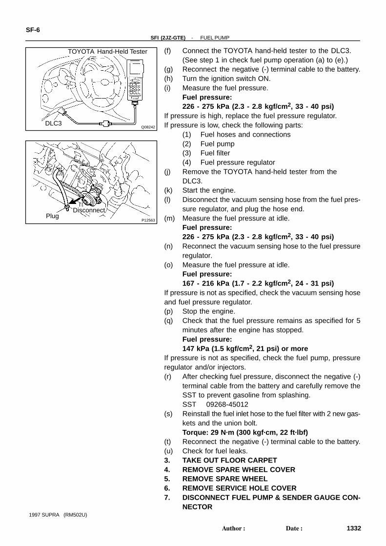
(f) Connect the TOYOTA hand-held tester to the DLC3.(See step 1 in check fuel pump operation (a) to (e).)
(g) Reconnect the negative (-) terminal cable to the battery.(h) Turn the ignition switch ON.(i) Measure the fuel pressure.
Fuel pressure:226 - 275 kPa (2.3 - 2.8 kgf/cm 2, 33 - 40 psi)
If pressure is high, replace the fuel pressure regulator.If pressure is low, check the following parts:
(1) Fuel hoses and connections(2) Fuel pump(3) Fuel filter(4) Fuel pressure regulator
(j) Remove the TOYOTA hand-held tester from theDLC3.
(k) Start the engine.(l) Disconnect the vacuum sensing hose from the fuel pres-
sure regulator, and plug the hose end.(m) Measure the fuel pressure at idle.
Fuel pressure:226 - 275 kPa (2.3 - 2.8 kgf/cm 2, 33 - 40 psi)
(n) Reconnect the vacuum sensing hose to the fuel pressureregulator.
(o) Measure the fuel pressure at idle.Fuel pressure:167 - 216 kPa (1.7 - 2.2 kgf/cm 2, 24 - 31 psi)
If pressure is not as specified, check the vacuum sensing hoseand fuel pressure regulator.(p) Stop the engine.(q) Check that the fuel pressure remains as specified for 5
minutes after the engine has stopped.Fuel pressure:147 kPa (1.5 kgf/cm 2, 21 psi) or more
If pressure is not as specified, check the fuel pump, pressureregulator and/or injectors.(r) After checking fuel pressure, disconnect the negative (-)
terminal cable from the battery and carefully remove theSST to prevent gasoline from splashing.SST 09268-45012
(s) Reinstall the fuel inlet hose to the fuel filter with 2 new gas-kets and the union bolt.Torque: 29 N·m (300 kgf·cm, 22 ft·lbf)
(t) Reconnect the negative (-) terminal cable to the battery.(u) Check for fuel leaks.3. TAKE OUT FLOOR CARPET4. REMOVE SPARE WHEEL COVER5. REMOVE SPARE WHEEL6. REMOVE SERVICE HOLE COVER7. DISCONNECT FUEL PUMP & SENDER GAUGE CON-
NECTOR
B01419
Ohmmeter 4
5
B01429
4
5
Battery
-SFI (2JZ-GTE) FUEL PUMPSF-7
1333Author: Date:
1997 SUPRA (RM502U)
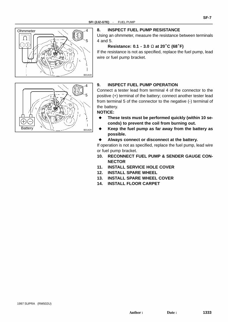
8. INSPECT FUEL PUMP RESISTANCEUsing an ohmmeter, measure the resistance between terminals4 and 5.
Resistance: 0.1 - 3.0 Ω at 20°C (68°F)If the resistance is not as specified, replace the fuel pump, leadwire or fuel pump bracket.
9. INSPECT FUEL PUMP OPERATIONConnect a tester lead from terminal 4 of the connector to thepositive (+) terminal of the battery; connect another tester leadfrom terminal 5 of the connector to the negative (-) terminal ofthe battery.NOTICE: These tests must be performed quickly (within 10 se-
conds) to prevent the coil from burning out. Keep the fuel pump as far away from the battery as
possible. Always connect or disconnect at the battery.
If operation is not as specified, replace the fuel pump, lead wireor fuel pump bracket.10. RECONNECT FUEL PUMP & SENDER GAUGE CON-
NECTOR11. INSTALL SERVICE HOLE COVER12. INSTALL SPARE WHEEL13. INSTALL SPARE WHEEL COVER14. INSTALL FLOOR CARPET
SF0GI-01
Z13599
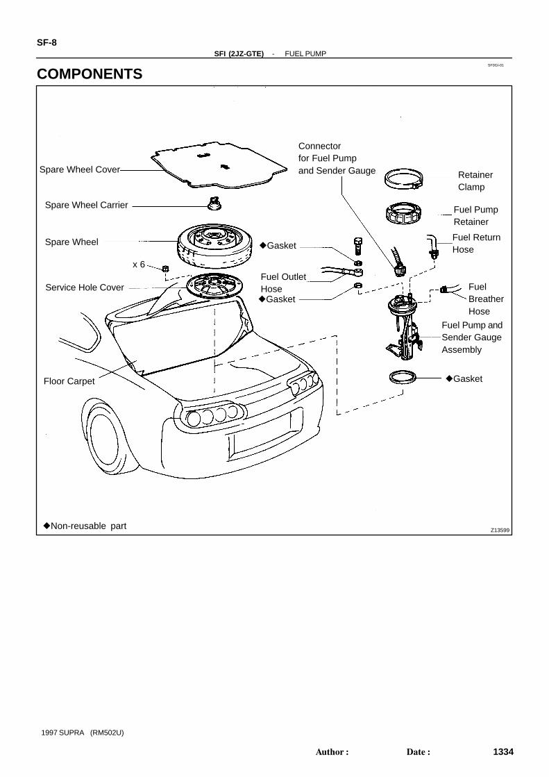
Spare Wheel Cover
Spare Wheel Carrier
Spare Wheel
Service Hole Cover
Floor Carpet
Connectorfor Fuel Pumpand Sender Gauge
Gasket
Fuel OutletHose
Fuel ReturnHose
Gasket
RetainerClamp
Gasket
FuelBreatherHose
Fuel Pump andSender GaugeAssembly
Non-reusable part
Fuel PumpRetainer
x 6
SF-8-SFI (2JZ-GTE) FUEL PUMP
1334Author: Date:
1997 SUPRA (RM502U)
COMPONENTS

P18050
Fuel Pump Filter
Fuel Sender Gauge
Fuel Hose
Lead Wirefor Fuel Pump
Fuel Pump
Rubber Cushion
ClipFuel Pump Bracket
Non-reusable part
-SFI (2JZ-GTE) FUEL PUMPSF-9
1335Author: Date:
1997 SUPRA (RM502U)
SF19Z-01
P11357
(1)(2)
(3)
(4)
P11280
SST
Rib
P12033
Fuel ReturnHose
SF-10-SFI (2JZ-GTE) FUEL PUMP
1336Author: Date:
1997 SUPRA (RM502U)
REMOVALCAUTION:Do not smoke or work near an open flame when working onthe fuel pump.1. TAKE OUT FLOOR CARPET2. REMOVE SPARE WHEEL COVER3. REMOVE SPARE WHEEL4. REMOVE SERVICE HOLE COVER
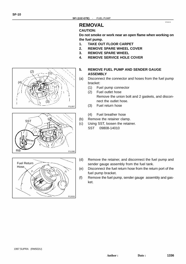
5. REMOVE FUEL PUMP AND SENDER GAUGEASSEMBLY
(a) Disconnect the connector and hoses from the fuel pumpbracket:(1) Fuel pump connector(2) Fuel outlet hose
Remove the union bolt and 2 gaskets, and discon-nect the outlet hose.
(3) Fuel return hose
(4) Fuel breather hose(b) Remove the retainer clamp.(c) Using SST, loosen the retainer.
SST 09808-14010
(d) Remove the retainer, and disconnect the fuel pump andsender gauge assembly from the fuel tank.
(e) Disconnect the fuel return hose from the return port of thefuel pump bracket.
(f) Remove the fuel pump, sender gauge assembly and gas-ket.

P11481
SF0GK-01
P11970
P11482Pull
P11971
Clip
-SFI (2JZ-GTE) FUEL PUMPSF-1 1
1337Author: Date:
1997 SUPRA (RM502U)
DISASSEMBLY1. REMOVE FUEL SENDER GAUGE FROM FUEL PUMP
BRACKET(a) Disconnect the connector from the fuel pump bracket.(b) Remove the 2 screws and sender gauge.
2. REMOVE FUEL PUMP FROM PUMP BRACKET(a) Remove the lead wire.
(b) Pull out the lower side of the fuel pump from the pumpbracket.
(c) Remove the rubber cushion from the fuel pump.(d) Disconnect the fuel hose from the fuel pump, and remove
the fuel pump.
3. REMOVE FUEL PUMP FILTER FROM FUEL PUMP(a) Using a small screwdriver, remove the clip.HINT:At the time of installation,please refer to the following items.Use a new clip.(b) Pull out the pump filter.
SF0GM-01
P12033
Fuel ReturnHose
P13168
Z09524
SST
Rib
Area
P11279
-SFI (2JZ-GTE) FUEL PUMPSF-13
1339Author: Date:
1997 SUPRA (RM502U)
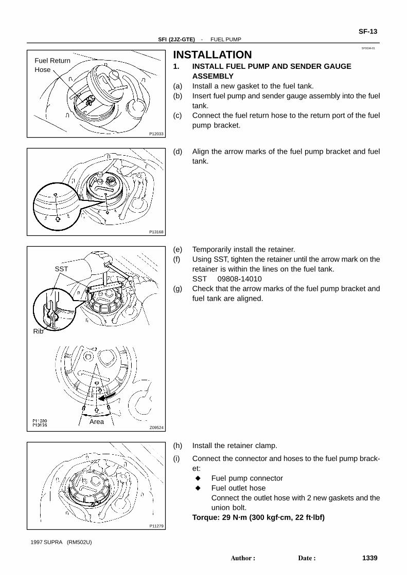
INSTALLATION1. INSTALL FUEL PUMP AND SENDER GAUGE
ASSEMBLY(a) Install a new gasket to the fuel tank.(b) Insert fuel pump and sender gauge assembly into the fuel
tank.(c) Connect the fuel return hose to the return port of the fuel
pump bracket.
(d) Align the arrow marks of the fuel pump bracket and fueltank.
(e) Temporarily install the retainer.(f) Using SST, tighten the retainer until the arrow mark on the
retainer is within the lines on the fuel tank.SST 09808-14010
(g) Check that the arrow marks of the fuel pump bracket andfuel tank are aligned.
(h) Install the retainer clamp.
(i) Connect the connector and hoses to the fuel pump brack-et: Fuel pump connector Fuel outlet hose
Connect the outlet hose with 2 new gaskets and theunion bolt.
Torque: 29 N·m (300 kgf·cm, 22 ft·lbf)
SF-14-SFI (2JZ-GTE) FUEL PUMP
1340Author: Date:
1997 SUPRA (RM502U)
Fuel return hose Fuel breather hose
2. INSTALL SERVICE HOLE COVER3. INSTALL SPARE WHEEL4. INSTALL SPARE WHEEL COVER5. INSTALL FLOOR CARPET6. CHECK FOR FUEL LEAKS

SF0GN-01
P18725
Fuel Pressure Regulator
O - Ring
Cruise Control Actuator Cable
Throttle Body
Sub-ThrottlePosition SensorConnector
Air Hose
Water Bypass Hose
PS Air Hose
Vacuum Sensing Hose
GasketFuel Return Pipe
Gasket
Accelerator
Throttle Position Sensor Connector
EVAP Hose
Sub-Throttle Actuator Connector
Gasket
Non-reusable part
-SFI (2JZ-GTE) FUEL PRESSURE REGULATORSF-15
1341Author: Date:
1997 SUPRA (RM502U)
FUEL PRESSURE REGULATORCOMPONENTS
SF0GO-01
P11323
FuelReturnPipe
VacuumSensingHose
P11324
SF-16-SFI (2JZ-GTE) FUEL PRESSURE REGULATOR
1342Author: Date:
1997 SUPRA (RM502U)
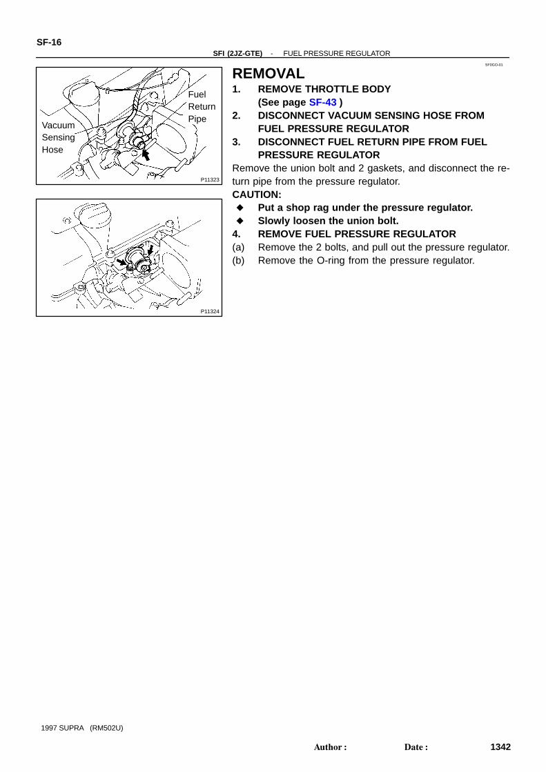
REMOVAL1. REMOVE THROTTLE BODY
(See page SF-43 )2. DISCONNECT VACUUM SENSING HOSE FROM
FUEL PRESSURE REGULATOR3. DISCONNECT FUEL RETURN PIPE FROM FUEL
PRESSURE REGULATORRemove the union bolt and 2 gaskets, and disconnect the re-turn pipe from the pressure regulator.CAUTION: Put a shop rag under the pressure regulator. Slowly loosen the union bolt.
4. REMOVE FUEL PRESSURE REGULATOR(a) Remove the 2 bolts, and pull out the pressure regulator.(b) Remove the O-ring from the pressure regulator.

SF0GP-01
B02654
New O-Ring
P13049
PressureRegulator
NewO - RingDeliveryPipe
CORRECT WRONGWRONG
P11324
-SFI (2JZ-GTE) FUEL PRESSURE REGULATORSF-17
1343Author: Date:
1997 SUPRA (RM502U)
INSTALLATION1. INSTALL FUEL PRESSURE REGULATOR(a) Apply a light coat of gasoline to a new O-ring, and install
it to the pressure regulator.
(b) Attach the pressure regulator to the delivery pipe.(c) Check that the pressure regulator rotates smoothly.NOTICE:If it does not rotate smoothly, the O-ring may be pinched,so remove the pressure regulator and do steps (b) and (c)above again.
(d) Install the pressure regulator with the 2 bolts.Torque: 9.0 N·m (90 kgf·cm, 80 in.·lbf)
2. CONNECT FUEL RETURN PIPE TO FUEL PRESSUREREGULATOR
Install the return pipe with 2 new gaskets and the union bolt.Torque: 28 N·m (280 kgf·cm, 21 ft·lbf)
3. CONNECT VACUUM SENSING HOSE TO FUELPRESSURE REGULATOR
4. INSTALL THROTTLE BODY(See page SF-48 )
5. CHECK FOR FUEL LEAKS(See page SF-1 )

P11358
Sound Scope
SF0GQ-01
P11359
P11416
Ohmmeter
SF-18-SFI (2JZ-GTE) INJECTOR
1344Author: Date:
1997 SUPRA (RM502U)
INJECTORON-VEHICLE INSPECTION1. INSPECT INJECTOR OPERATIONCheck operation sound from each injector.
(1) With the engine running or cranking, use a soundscope to check that there is normal operating noisein proportion to engine speed.
(2) If you have no sound scope, you can check the in-jector transmission operation with your finger.
If no sound is heard or unusual vibration is felt, check the wiringconnector, injector or injection signal from the ECM.
2. INSPECT INJECTOR RESISTANCE(a) Disconnect the throttle body without disconnecting the
water bypass hoses from the air intake chamber.(See page SF-42 )
(b) Disconnect the 6 injector connectors.(c) Using an ohmmeter, measure the resistance between the
injector terminals.Resistance: Approx. 1.95 Ω at 20°C (68°F)
If the resistance is not as specified, replace the injector.(d) Reconnect the 6 injector connectors.(e) Reinstall the throttle body to the air intake chamber.
(See page SF-48 )

SF0GR-01
S04780
Engine WireProtector
Air Intake Chamber Stay
IAC Valve Connector
VSV Connector for EGR
Turbo Pressure Sensor ConnectorVSV Connector for Fuel Pressure Control
Water Bypass Hose
Control Cable Bracket and Cable
Vacuum Hose
IAC Valve PipeEVAP Hose
Gasket
EGR PipeBrake BoosterVacuum Hose
EngineWireProtector
Engine Wire Bracket
Engine Wire Clamp
GroundCable
EGR Gas TemperatureSensor Connector
Manifold Stay
No.4 Water Bypass PipeWater Bypass Hose
Air IntakeChamber
PS Air Hose
Injector ConnectorEngine WireClamp
InsulatorInjector O - Ring
Vacuum Sensing Hose
SpacerDelivery Pipe
Fuel Return Pipe
Sub-Throttle PositionSensor Connector
Injector Holderx3
Fuel Inlet Pipe
PCV Hose
Oil Dipstick and Guide for A/T
Gasket
Gasket
Air Hose
PS Air Hose
Water Bypass Hose
Sub - Throttle ActuatorConnector
Engine Under Cover
Gasket Insulator
Spacer
Fuel Return HoseThrottle Body
Throttle PositionSensor Connector
Oil Dipstick and Guidefor Engine
O - Ring
O - Ring
Gasket
Gasket
Non - reusable part
-SFI (2JZ-GTE) INJECTORSF-19
1345Author: Date:
1997 SUPRA (RM502U)
COMPONENTS
SF0GS-02
P12565
Pull
O-Ring
S00910
Engine Wire ClampO-Ring
Pull
FuelReturnHose
P11322
ChamberStag
CableBracket
P11321(1) (2) (3)
(4)
SF-20-SFI (2JZ-GTE) INJECTOR
1346Author: Date:
1997 SUPRA (RM502U)
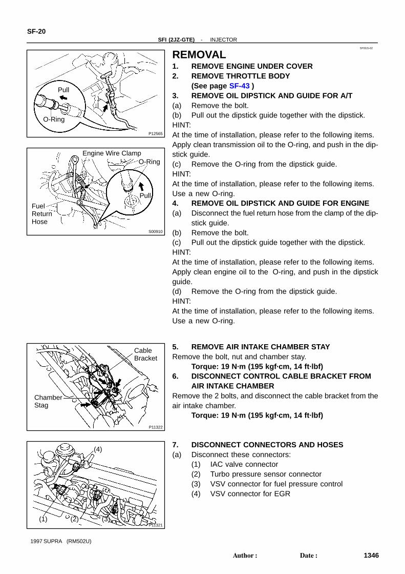
REMOVAL1. REMOVE ENGINE UNDER COVER2. REMOVE THROTTLE BODY
(See page SF-43 )3. REMOVE OIL DIPSTICK AND GUIDE FOR A/T(a) Remove the bolt.(b) Pull out the dipstick guide together with the dipstick.HINT:At the time of installation, please refer to the following items.Apply clean transmission oil to the O-ring, and push in the dip-stick guide.(c) Remove the O-ring from the dipstick guide.HINT:At the time of installation, please refer to the following items.Use a new O-ring.4. REMOVE OIL DIPSTICK AND GUIDE FOR ENGINE(a) Disconnect the fuel return hose from the clamp of the dip-
stick guide.(b) Remove the bolt.(c) Pull out the dipstick guide together with the dipstick.HINT:At the time of installation, please refer to the following items.Apply clean engine oil to the O-ring, and push in the dipstickguide.(d) Remove the O-ring from the dipstick guide.HINT:At the time of installation, please refer to the following items.Use a new O-ring.
5. REMOVE AIR INTAKE CHAMBER STAYRemove the bolt, nut and chamber stay.
Torque: 19 N·m (195 kgf·cm, 14 ft·lbf)6. DISCONNECT CONTROL CABLE BRACKET FROM
AIR INTAKE CHAMBERRemove the 2 bolts, and disconnect the cable bracket from theair intake chamber.
Torque: 19 N·m (195 kgf·cm, 14 ft·lbf)
7. DISCONNECT CONNECTORS AND HOSES(a) Disconnect these connectors:
(1) IAC valve connector(2) Turbo pressure sensor connector(3) VSV connector for fuel pressure control(4) VSV connector for EGR

P11991
P11317
(1)(2)
(3)
Clamp
P11318(4) (5)
S04464
(10)
(8)(6) (7)
(9)
(11)
S04463
EGR GasTemperatureSensorConnector
EGR Pipe
-SFI (2JZ-GTE) INJECTORSF-21
1347Author: Date:
1997 SUPRA (RM502U)
(b) Remove the bolt, and disconnect the engine wire protec-tor from the body.
(c) Disconnect these hoses:(1) Air hose from IAC valve
Disconnect the IAC valve pipe from the clamp onthe cylinder head cover, and disconnect the air hosefrom the IAC valve.
(2) Air hose (from air intake chamber) fromvacuum pipe on IAC valve pipe
(3) Air hose for EGR from valve pipe
(4) PCV hose from PCV valve(5) Vacuum sensing hose from fuel pressure
regulator
(6) Water bypass hose (from IAC valve) from No.4 wa-ter bypass pipe
(7) EVAP hose (from air intake chamber) fromvacuum pipe on manifold stay
(8) EVAP hose (from vacuum pipe on No.4 waterbypass pipe) from No.2 vacuum pipe
(9) EVAP hose (from charcoal canister) from No.2vacuum pipe
(10) PS air hose from air intake chamber(11) Brake booster vacuum hose from union on air in-
take chamber8. DISCONNECT EGR GAS TEMPERATURE SENSOR
CONNECTOR(a) Disconnect the connector from the No.2 vacuum pipe.(b) Disconnect the sensor connector from the wiring connec-
tor.9. REMOVE EGR PIPE(a) Remove the union bolt holding the EGR pipe to the EGR
valve.Torque: 64 N·m (650 kgf·cm, 47 ft·lbf)
P11315
No.4 WaterBypass Pipe
Manifold Stay
P11314
Clamp
GroundCable
S04462
P11312
Water
HoseBypass
Z09317(3)
Gray
Dark
(1)
(2)Gray(1)
Gray(1)
DarkGray(1)
(2) Gray(1)
DarkGray(1)
SF-22-SFI (2JZ-GTE) INJECTOR
1348Author: Date:
1997 SUPRA (RM502U)
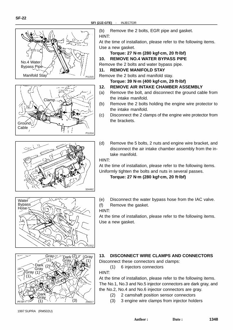
(b) Remove the 2 bolts, EGR pipe and gasket.HINT:At the time of installation, please refer to the following items.Use a new gasket.
Torque: 27 N·m (280 kgf·cm, 20 ft·lbf)10. REMOVE NO.4 WATER BYPASS PIPERemove the 2 bolts and water bypass pipe.11. REMOVE MANIFOLD STAYRemove the 2 bolts and manifold stay.
Torque: 39 N·m (400 kgf·cm, 29 ft·lbf)12. REMOVE AIR INTAKE CHAMBER ASSEMBLY(a) Remove the bolt, and disconnect the ground cable from
the intake manifold.(b) Remove the 2 bolts holding the engine wire protector to
the intake manifold.(c) Disconnect the 2 clamps of the engine wire protector from
the brackets.
(d) Remove the 5 bolts, 2 nuts and engine wire bracket, anddisconnect the air intake chamber assembly from the in-take manifold.
HINT:At the time of installation, please refer to the following items.Uniformly tighten the bolts and nuts in several passes.
Torque: 27 N·m (280 kgf·cm, 20 ft·lbf)
(e) Disconnect the water bypass hose from the IAC valve.(f) Remove the gasket.HINT:At the time of installation, please refer to the following items.Use a new gasket.
13. DISCONNECT WIRE CLAMPS AND CONNECTORSDisconnect these connectors and clamps:
(1) 6 injectors connectorsHINT:At the time of installation, please refer to the following items.The No.1, No.3 and No.5 injector connectors are dark gray, andthe No.2, No.4 and No.6 injector connectors are gray.
(2) 2 camshaft position sensor connectors(3) 3 engine wire clamps from injector holders
P11310
FuelReturnPipe Fuel
InletPipe
P11309
Z09319
Insulator
P11307
P11305
Spacer
-SFI (2JZ-GTE) INJECTORSF-23
1349Author: Date:
1997 SUPRA (RM502U)
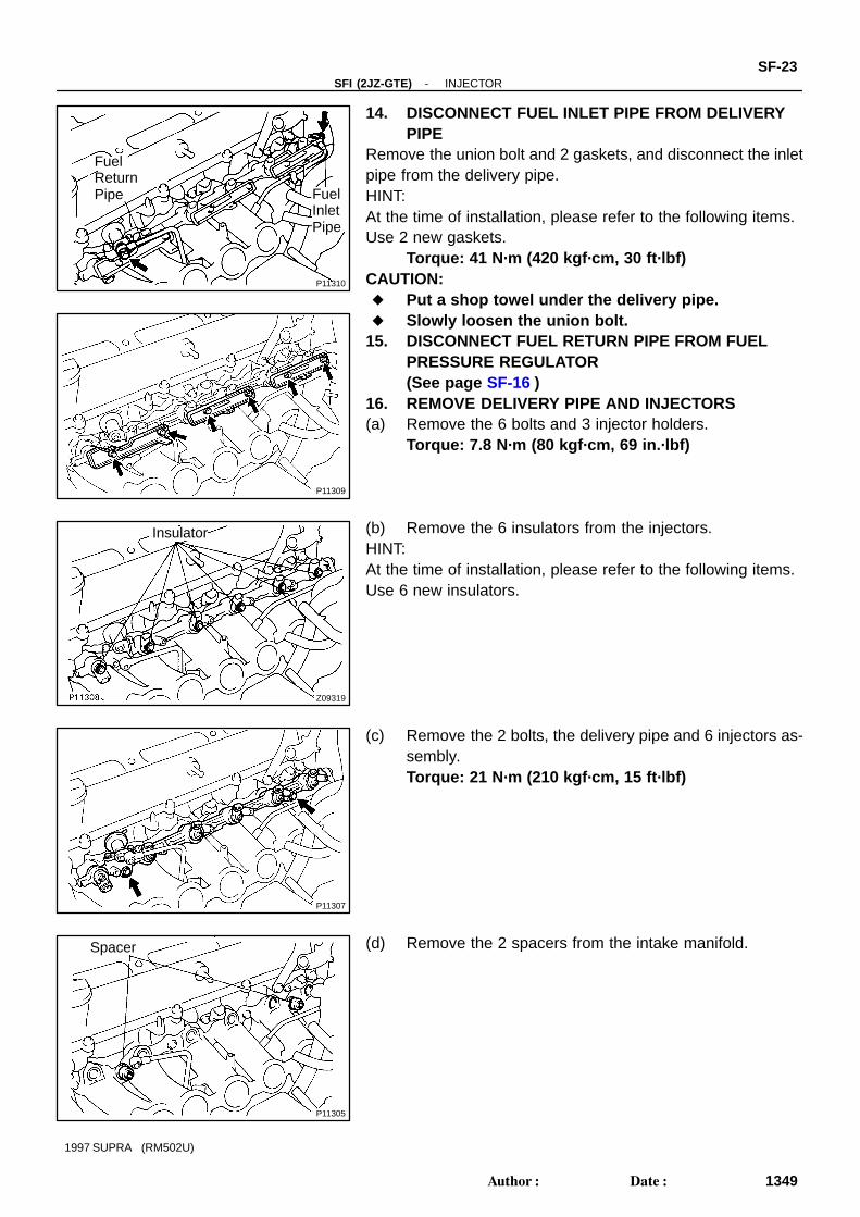
14. DISCONNECT FUEL INLET PIPE FROM DELIVERYPIPE
Remove the union bolt and 2 gaskets, and disconnect the inletpipe from the delivery pipe.HINT:At the time of installation, please refer to the following items.Use 2 new gaskets.
Torque: 41 N·m (420 kgf·cm, 30 ft·lbf)CAUTION: Put a shop towel under the delivery pipe. Slowly loosen the union bolt.
15. DISCONNECT FUEL RETURN PIPE FROM FUELPRESSURE REGULATOR(See page SF-16 )
16. REMOVE DELIVERY PIPE AND INJECTORS(a) Remove the 6 bolts and 3 injector holders.
Torque: 7.8 N·m (80 kgf·cm, 69 in.·lbf)
(b) Remove the 6 insulators from the injectors.HINT:At the time of installation, please refer to the following items.Use 6 new insulators.
(c) Remove the 2 bolts, the delivery pipe and 6 injectors as-sembly.Torque: 21 N·m (210 kgf·cm, 15 ft·lbf)
(d) Remove the 2 spacers from the intake manifold.
Z09318
Insulator
SF-24-SFI (2JZ-GTE) INJECTOR
1350Author: Date:
1997 SUPRA (RM502U)
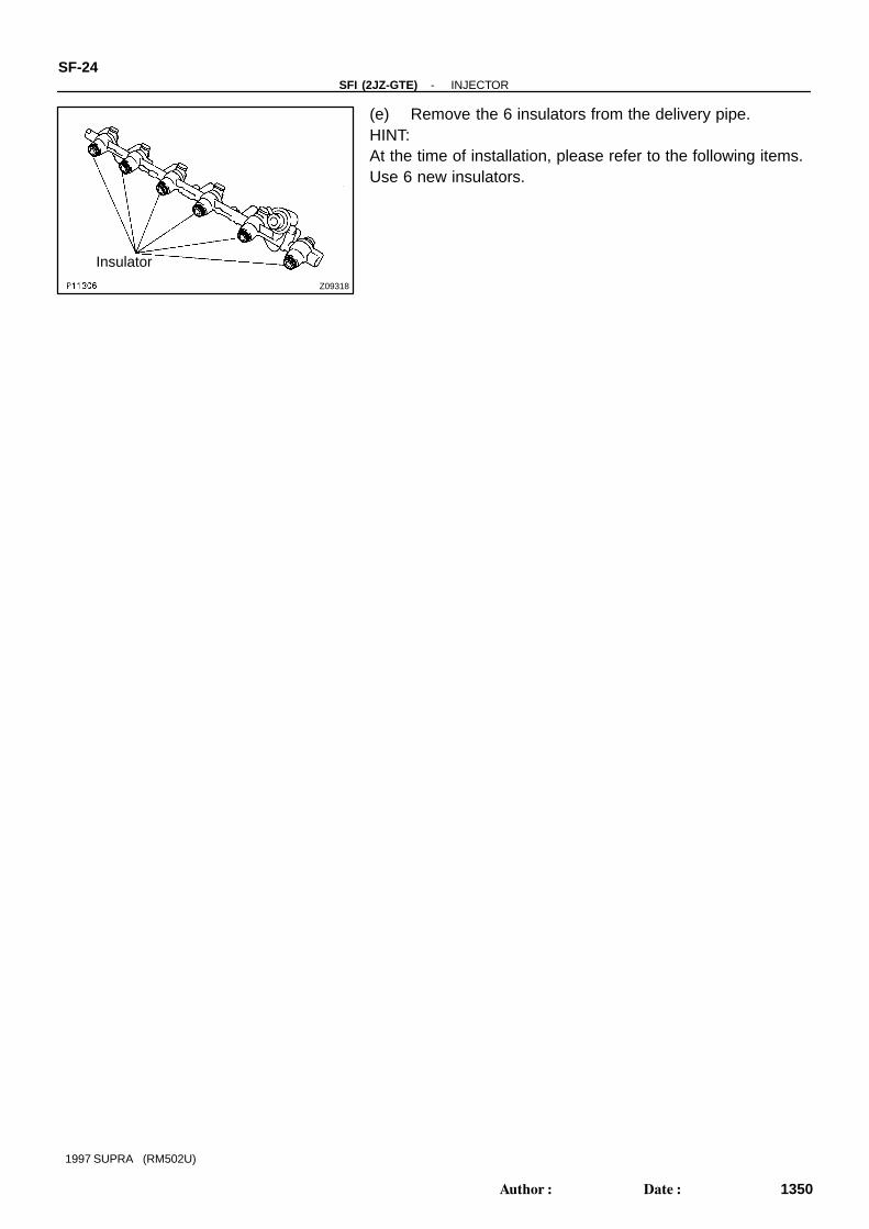
(e) Remove the 6 insulators from the delivery pipe.HINT:At the time of installation, please refer to the following items.Use 6 new insulators.
SF0GT-02
P12826
Injector
Fuel Pressure Regulator
SST(Union)
Fuel Return Hose(On Vehicle) SST
(Union)
Fuel Filter(On Vehicle)
SST(Hose)
SSTUnion
Delivery Pipe
P11302
Insulator
P12558
Fuel InletHose
-SFI (2JZ-GTE) INJECTORSF-25
1351Author: Date:
1997 SUPRA (RM502U)
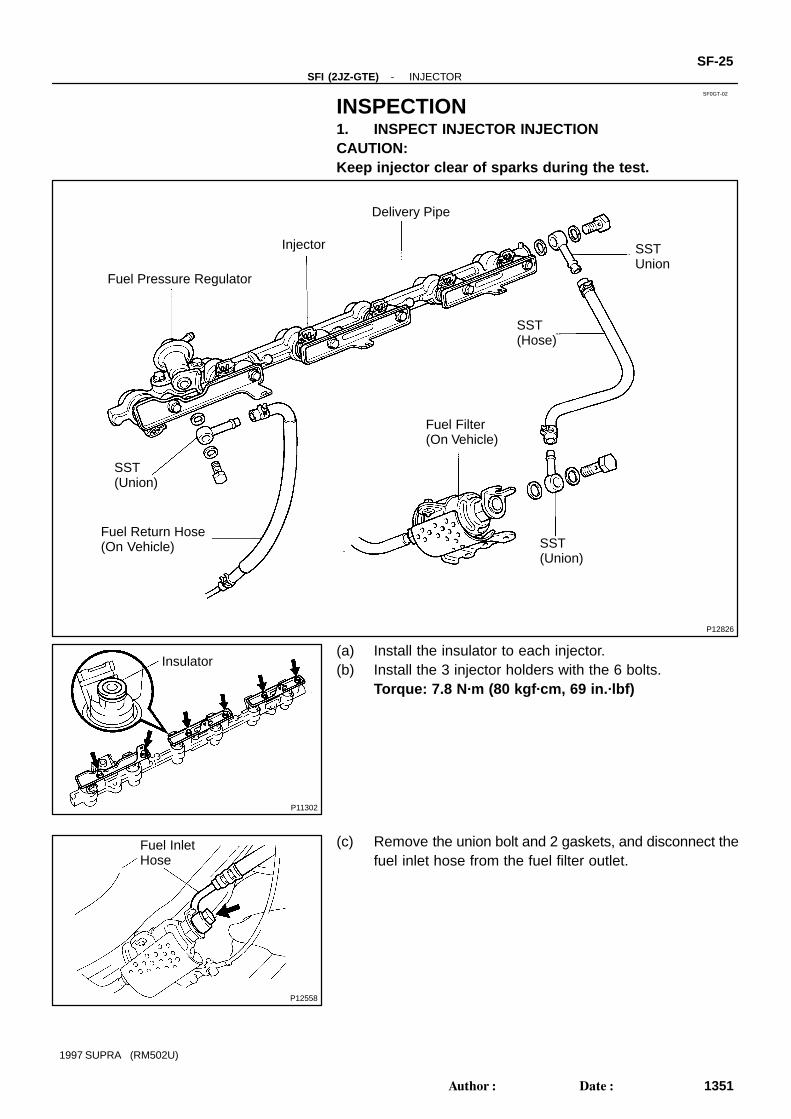
INSPECTION1. INSPECT INJECTOR INJECTIONCAUTION:Keep injector clear of sparks during the test.
(a) Install the insulator to each injector.(b) Install the 3 injector holders with the 6 bolts.
Torque: 7.8 N·m (80 kgf·cm, 69 in.·lbf)
(c) Remove the union bolt and 2 gaskets, and disconnect thefuel inlet hose from the fuel filter outlet.

Z13305
SST(Union)
SST(Hose)
UnionBolt
Gasket
P12559Fuel Return Hose
Z13308
Fuel ReturnHose
SST(Union)
GasketUnionBolt
Z13304
SST (Union)
Gasket
UnionBolt
SST (Hose)
SF-26-SFI (2JZ-GTE) INJECTOR
1352Author: Date:
1997 SUPRA (RM502U)
(d) Connect SST (hose) to the fuel filter outlet with SST(union), the 2 gaskets and union bolt.SST 09268-41046 (90405-09015)Torque: 29 N·m (300 kgf·cm, 22 ft·lbf)
(e) Disconnect the fuel return hose from the fuel return pipe.
(f) Connect the fuel return hose to the fuel outlet of the pres-sure regulator on the delivery pipe with SST (union), the2 gaskets and union bolt.SST 09268-41046 (09268-41071)
(g) Connect SST (hose) to the fuel inlet of the delivery pipewith SST (union), the 2 gaskets and union bolt.SST 09268-41046 (90405-09015)
(h) Put the injector into the graduated cylinder.
Q08242
TOYOTA Hand-Held Tester
DLC3
P12548
SST (Wire)
Connect
P12549
-SFI (2JZ-GTE) INJECTORSF-27
1353Author: Date:
1997 SUPRA (RM502U)
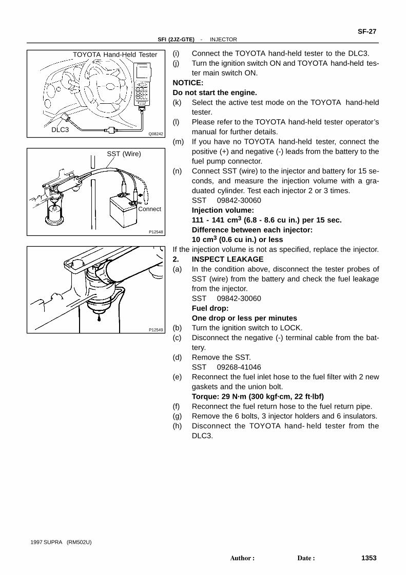
(i) Connect the TOYOTA hand-held tester to the DLC3.(j) Turn the ignition switch ON and TOYOTA hand-held tes-
ter main switch ON.NOTICE:Do not start the engine.(k) Select the active test mode on the TOYOTA hand-held
tester.(l) Please refer to the TOYOTA hand-held tester operator’s
manual for further details.(m) If you have no TOYOTA hand-held tester, connect the
positive (+) and negative (-) leads from the battery to thefuel pump connector.
(n) Connect SST (wire) to the injector and battery for 15 se-conds, and measure the injection volume with a gra-duated cylinder. Test each injector 2 or 3 times.SST 09842-30060Injection volume:111 - 141 cm3 (6.8 - 8.6 cu in.) per 15 sec.Difference between each injector:10 cm3 (0.6 cu in.) or less
If the injection volume is not as specified, replace the injector.2. INSPECT LEAKAGE(a) In the condition above, disconnect the tester probes of
SST (wire) from the battery and check the fuel leakagefrom the injector.SST 09842-30060Fuel drop:One drop or less per minutes
(b) Turn the ignition switch to LOCK.(c) Disconnect the negative (-) terminal cable from the bat-
tery.(d) Remove the SST.
SST 09268-41046(e) Reconnect the fuel inlet hose to the fuel filter with 2 new
gaskets and the union bolt.Torque: 29 N·m (300 kgf·cm, 22 ft·lbf)
(f) Reconnect the fuel return hose to the fuel return pipe.(g) Remove the 6 bolts, 3 injector holders and 6 insulators.(h) Disconnect the TOYOTA hand- held tester from the
DLC3.
SF0GU-01
P13047Gasoline
Gasoline
P11300
Push
SST
Push
P11303
NewO-Ring
NewInsulator
Z09022
Push
Connector
Push
SF-28-SFI (2JZ-GTE) INJECTOR
1354Author: Date:
1997 SUPRA (RM502U)
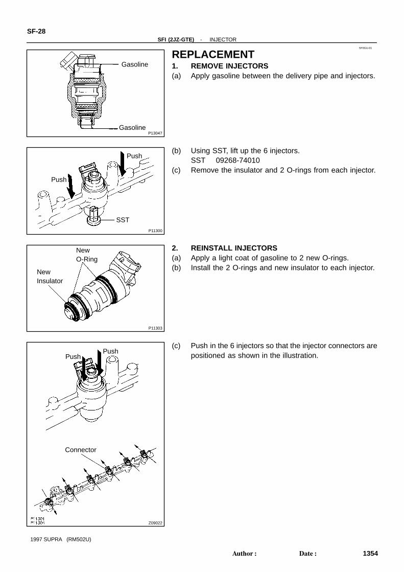
REPLACEMENT1. REMOVE INJECTORS(a) Apply gasoline between the delivery pipe and injectors.
(b) Using SST, lift up the 6 injectors.SST 09268-74010
(c) Remove the insulator and 2 O-rings from each injector.
2. REINSTALL INJECTORS(a) Apply a light coat of gasoline to 2 new O-rings.(b) Install the 2 O-rings and new insulator to each injector.
(c) Push in the 6 injectors so that the injector connectors arepositioned as shown in the illustration.
SF0GW-01
P18730
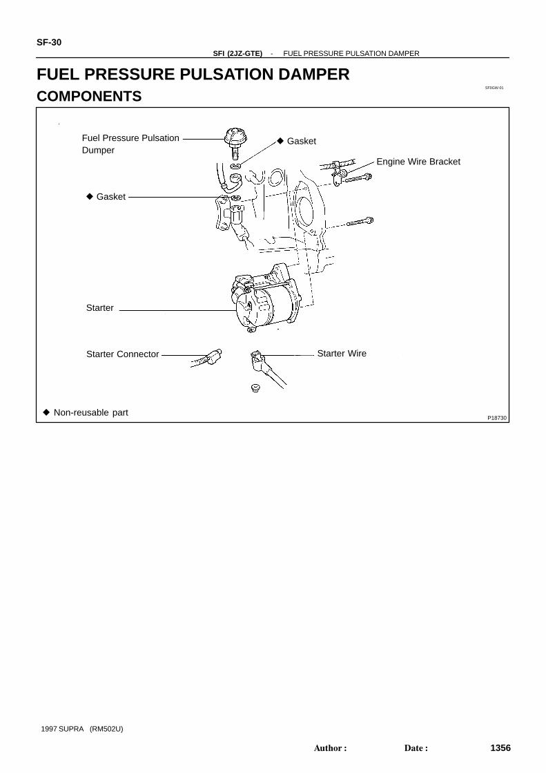
Fuel Pressure PulsationDumper
Gasket
Starter
Starter Connector
Engine Wire Bracket
Starter Wire
Gasket
Non-reusable part
SF-30-SFI (2JZ-GTE) FUEL PRESSURE PULSATION DAMPER
1356Author: Date:
1997 SUPRA (RM502U)
FUEL PRESSURE PULSATION DAMPERCOMPONENTS
SF0GX-01
B02655
SST
-SFI (2JZ-GTE) FUEL PRESSURE PULSATION DAMPERSF-31
1357Author: Date:
1997 SUPRA (RM502U)
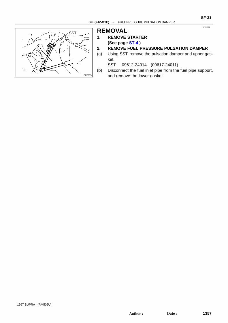
REMOVAL1. REMOVE STARTER
(See page ST-4 )2. REMOVE FUEL PRESSURE PULSATION DAMPER(a) Using SST, remove the pulsation damper and upper gas-
ket.SST 09612-24014 (09617-24011)
(b) Disconnect the fuel inlet pipe from the fuel pipe support,and remove the lower gasket.
SF0GY-02
B02656
NewGasket(Large)
NewGasket(Small)
B02657
FulcrumLength
SST
SF-32-SFI (2JZ-GTE) FUEL PRESSURE PULSATION DAMPER
1358Author: Date:
1997 SUPRA (RM502U)
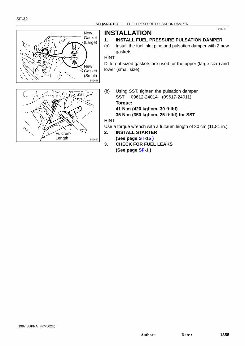
INSTALLATION1. INSTALL FUEL PRESSURE PULSATION DAMPER(a) Install the fuel inlet pipe and pulsation damper with 2 new
gaskets.HINT:Different sized gaskets are used for the upper (large size) andlower (small size).
(b) Using SST, tighten the pulsation damper.SST 09612-24014 (09617-24011)Torque:41 N·m (420 kgf·cm, 30 ft·lbf)35 N·m (350 kgf·cm, 25 ft·lbf) for SST
HINT:Use a torque wrench with a fulcrum length of 30 cm (11.81 in.).2. INSTALL STARTER
(See page ST-15 )3. CHECK FOR FUEL LEAKS
(See page SF-1 )

SF0H0-02
P20903
No.2 Fuel TankProtector
Fuel InletPipe Shield
Fuel Tank Cap
Fuel PumpRetainer
Fuel Pump and
Gasket
Fuel Breather Pipe
Fuel Tank Band
Fuel Tank Protector
Fuel Tank
EVAP Hose
Retainer Clamp
Fuel Outlet Pipe
Fuel returnHose
Fuel Return Hose
Gasket
Gasket
Sender GaugeAssembly
Non-reusable part
SF-34-SFI (2JZ-GTE) FUEL TANK AND LINE
1360Author: Date:
1997 SUPRA (RM502U)
COMPONENTS

SF0H1-01
BO0919
Crack Leakage
FI1654
SST Use SST
(310 kgf·cm, 22 ft·lbf)
Fulcrum Length
(11.81 in.)
SST : 09631 - 22020
30 N·m
30 cm
FU0041
Pipe
2 - 7mm(0.08-0.28 in.)
Hose
Clip
0 -3mm(0 - 0.12 in.)
-SFI (2JZ-GTE) FUEL TANK AND LINESF-35
1361Author: Date:
1997 SUPRA (RM502U)
INSPECTIONINSPECT FUEL TANK AND LINE(a) Check the fuel lines for cracks or leakage, and all connec-
tions for deformation.(b) Check the fuel tank vapor vent system hoses and connec-
tions for looseness, sharp bends or damage.(c) Check the fuel tank for deformation, cracks, fuel leakage
or tank band looseness.(d) Check the filler neck for damage or fuel leakage.(e) Hose and tube connections are as shown in the illustra-
tion.If a problem is found, repair or replace the part as necessary.
SF0H2-01
P18727
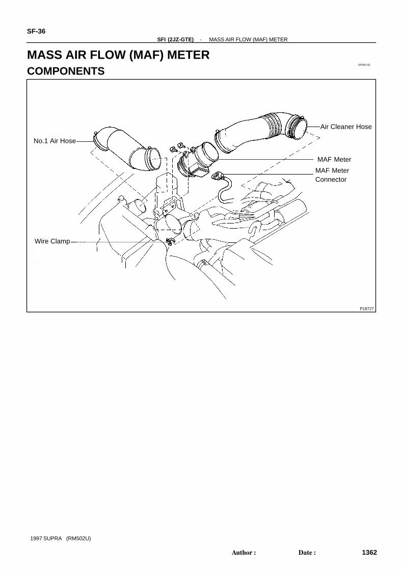
No.1 Air Hose
Wire Clamp
Air Cleaner Hose
MAF MeterConnector
MAF Meter
SF-36-SFI (2JZ-GTE) MASS AIR FLOW (MAF) METER
1362Author: Date:
1997 SUPRA (RM502U)
MASS AIR FLOW (MAF) METERCOMPONENTS

SF0H3-01
P12084
Clamp
Connector
-SFI (2JZ-GTE) MASS AIR FLOW (MAF) METERSF-37
1363Author: Date:
1997 SUPRA (RM502U)
REMOVAL1. REMOVE NO.1 AIR HOSE2. REMOVE AIR CLEANER HOSE3. REMOVE MAF METER(a) Remove the 2 bolts, and disconnect the MAF meter from
the air cleaner case.Torque: 6.9 N·m (70 kgf·cm, 61 in.·lbf)
(b) Disconnect the MAF meter wire from the wire clamp onthe air cleaner case.
(c) Disconnect the MAF meter connector, and remove theMAF meter.

SF0H4-01
FI6961
E2 THa
Ohmmeter
P12997
Voltmeter
VG
E21
Air
SF-38-SFI (2JZ-GTE) MASS AIR FLOW (MAF) METER
1364Author: Date:
1997 SUPRA (RM502U)
INSPECTION1. INSPECT MAF METER RESISTANCEUsing an ohmmeter, measure the resistance between terminalsTHA and E2.
Resistance:
-20 °C (-4°F) 10 - 20 kΩ
0°C (32°F) 4 - 7 kΩ
20°C (68°F) 2 - 3 kΩ
40°C (104°F) 0.9 - 1.3 kΩ
60°C (140°F) 0.4 - 0.7 kΩ
If the resistance is not as specified, replace the MAF meter.
2. INSPECT MAF METER OPERATION(a) Connectfthe MAF meter connector.(b) Connectfthe negative (-) terminal cable to the battery.(c) Using a voltmeter, connect the positive (+) tester probe to
terminal VG, and negative (-) tester probe to terminalE21.
(d) Turn the ignition switch ON.(e) Blow air into the MAF meter, and check that the voltage
fluctuates.If operation is not as specified, replace the MAF meter.(f) Turn the ignition switch OFF.(g) Disconnect the negative (-) terminal cable from the bat-
tery.(h) Disconnect the MAF meter connector.
P11325
SF0H6-01
P12079
P12560
Turn
DashpotAdjusting Screw
Push Rod
SF-40-SFI (2JZ-GTE) THROTTLE BODY
1366Author: Date:
1997 SUPRA (RM502U)
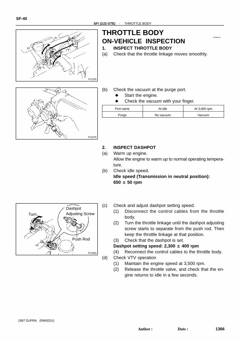
THROTTLE BODYON-VEHICLE INSPECTION1. INSPECT THROTTLE BODY(a) Check that the throttle linkage moves smoothly.
(b) Check the vacuum at the purge port. Start the engine. Check the vacuum with your finger.
Port name At idle At 3,000 rpm
Purge No vacuum Vacuum
2. INSPECT DASHPOT(a) Warm up engine.
Allow the engine to warm up to normal operating tempera-ture.
(b) Check idle speed.Idle speed (Transmission in neutral position):650 ± 50 rpm
(c) Check and adjust dashpot setting speed.(1) Disconnect the control cables from the throttle
body.(2) Turn the throttle linkage until the dashpot adjusting
screw starts to separate from the push rod. Thenkeep the throttle linkage at that position.
(3) Check that the dashpot is set.Dashpot setting speed: 2,300 ± 400 rpm(4) Reconnect the control cables to the throttle body.
(d) Check VTV operation(1) Maintain the engine speed at 3,500 rpm.(2) Release the throttle valve, and check that the en-
gine returns to idle in a few seconds.
Z13303
Disconnect
Plug
ThrottleOpenerAdjustingScrew
-SFI (2JZ-GTE) THROTTLE BODYSF-41
1367Author: Date:
1997 SUPRA (RM502U)
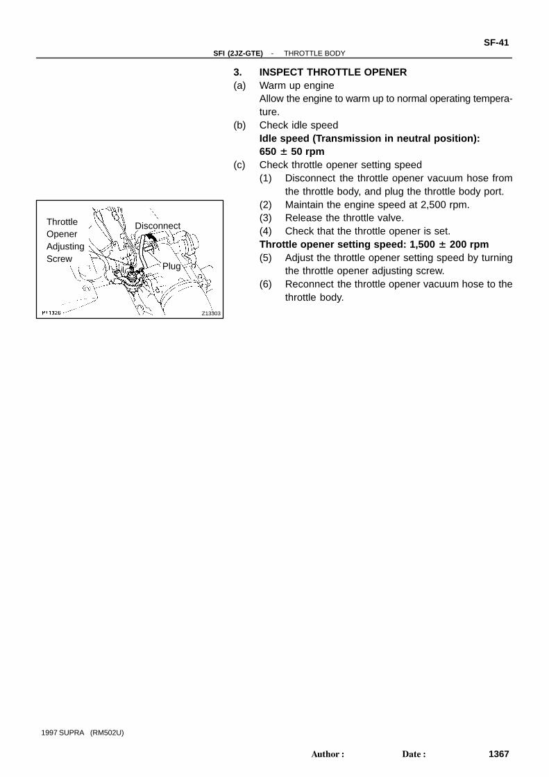
3. INSPECT THROTTLE OPENER(a) Warm up engine
Allow the engine to warm up to normal operating tempera-ture.
(b) Check idle speedIdle speed (Transmission in neutral position):650 ± 50 rpm
(c) Check throttle opener setting speed(1) Disconnect the throttle opener vacuum hose from
the throttle body, and plug the throttle body port.(2) Maintain the engine speed at 2,500 rpm.(3) Release the throttle valve.(4) Check that the throttle opener is set.Throttle opener setting speed: 1,500 ± 200 rpm(5) Adjust the throttle opener setting speed by turning
the throttle opener adjusting screw.(6) Reconnect the throttle opener vacuum hose to the
throttle body.
SF0H7-01
P18724
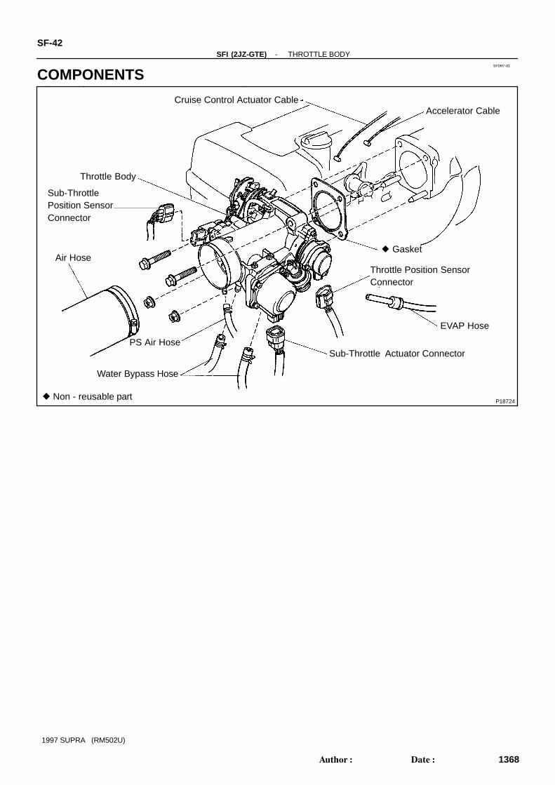
Cruise Control Actuator Cable
Throttle Body
Sub-ThrottlePosition SensorConnector
PS Air Hose
Air Hose Gasket
Throttle Position SensorConnector
Sub-Throttle Actuator Connector
EVAP Hose
Water Bypass Hose
Accelerator Cable
Non - reusable part
SF-42-SFI (2JZ-GTE) THROTTLE BODY
1368Author: Date:
1997 SUPRA (RM502U)
COMPONENTS
P11327
(4)
(3)
(2)
(!)
(5)
(6)
P11328
SF0H8-01
P11329
(1)
(2)
(3)
(4)
-SFI (2JZ-GTE) THROTTLE BODYSF-43
1369Author: Date:
1997 SUPRA (RM502U)
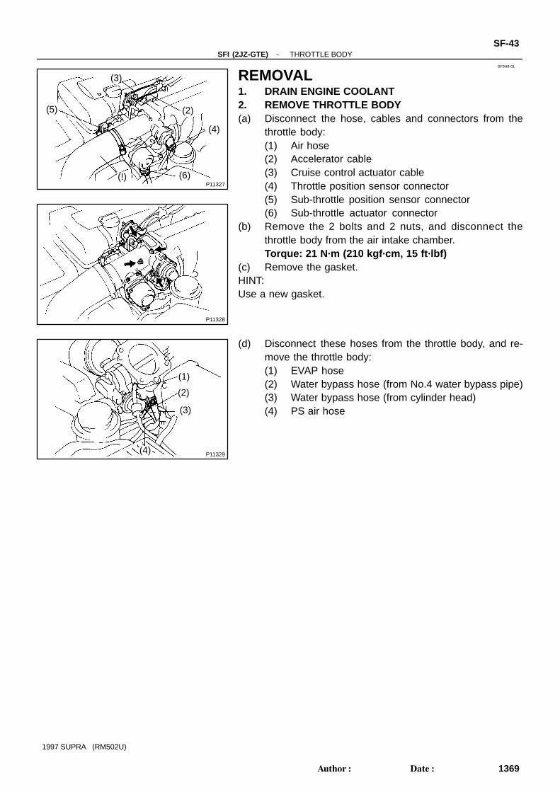
REMOVAL1. DRAIN ENGINE COOLANT2. REMOVE THROTTLE BODY(a) Disconnect the hose, cables and connectors from the
throttle body:(1) Air hose(2) Accelerator cable(3) Cruise control actuator cable(4) Throttle position sensor connector(5) Sub-throttle position sensor connector(6) Sub-throttle actuator connector
(b) Remove the 2 bolts and 2 nuts, and disconnect thethrottle body from the air intake chamber.Torque: 21 N·m (210 kgf·cm, 15 ft·lbf)
(c) Remove the gasket.HINT:Use a new gasket.
(d) Disconnect these hoses from the throttle body, and re-move the throttle body:(1) EVAP hose(2) Water bypass hose (from No.4 water bypass pipe)(3) Water bypass hose (from cylinder head)(4) PS air hose
SF0H9-02
P11982
P11488
Throttle Lever
Throttle Stop Screw
Vacuum
NoClearance Disconnect
P11489
Vacuum
DisconnectFeelerGauge
Z09088
Ohmmeter
VTAVC
E2 IDL
P11453
SF-44-SFI (2JZ-GTE) THROTTLE BODY
1370Author: Date:
1997 SUPRA (RM502U)
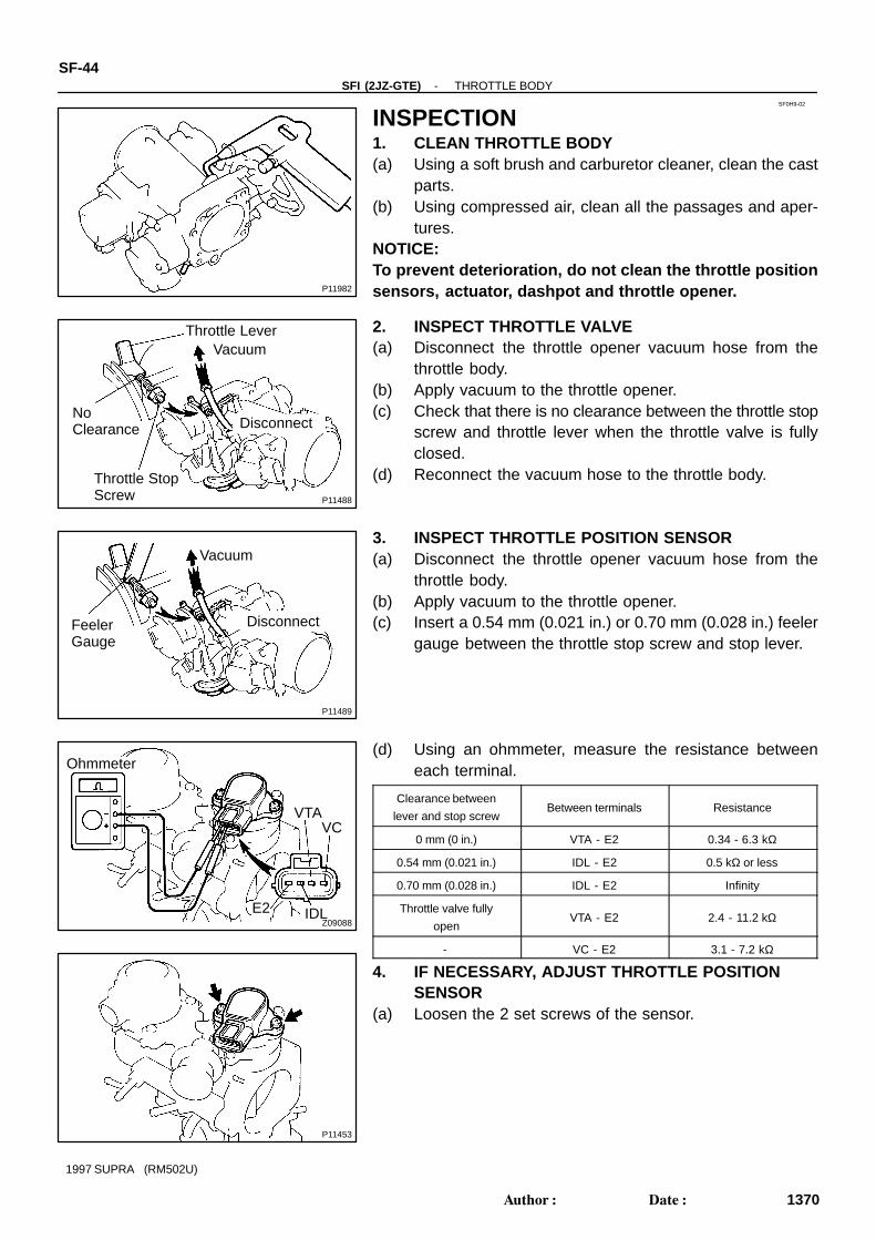
INSPECTION1. CLEAN THROTTLE BODY(a) Using a soft brush and carburetor cleaner, clean the cast
parts.(b) Using compressed air, clean all the passages and aper-
tures.NOTICE:To prevent deterioration, do not clean the throttle positionsensors, actuator, dashpot and throttle opener.
2. INSPECT THROTTLE VALVE(a) Disconnect the throttle opener vacuum hose from the
throttle body.(b) Apply vacuum to the throttle opener.(c) Check that there is no clearance between the throttle stop
screw and throttle lever when the throttle valve is fullyclosed.
(d) Reconnect the vacuum hose to the throttle body.
3. INSPECT THROTTLE POSITION SENSOR(a) Disconnect the throttle opener vacuum hose from the
throttle body.(b) Apply vacuum to the throttle opener.(c) Insert a 0.54 mm (0.021 in.) or 0.70 mm (0.028 in.) feeler
gauge between the throttle stop screw and stop lever.
(d) Using an ohmmeter, measure the resistance betweeneach terminal.
Clearance between
lever and stop screwBetween terminals Resistance
0 mm (0 in.) VTA - E2 0.34 - 6.3 kΩ
0.54 mm (0.021 in.) IDL - E2 0.5 kΩ or less
0.70 mm (0.028 in.) IDL - E2 Infinity
Throttle valve fully
openVTA - E2 2.4 - 11.2 kΩ
- VC - E2 3.1 - 7.2 kΩ
4. IF NECESSARY, ADJUST THROTTLE POSITIONSENSOR
(a) Loosen the 2 set screws of the sensor.

Z09125
0.65 mm
S00022
Ohmmeter
IDLE2
Turn
B02446
B02858
0.54 or 0.70 mm
Ohmmeter
E2 IDL
P11455
Ohmmeter
A
B
A-B-
-SFI (2JZ-GTE) THROTTLE BODYSF-45
1371Author: Date:
1997 SUPRA (RM502U)
(b) Insert a 0.65 mm (0.026 in.) feeler gauge between thethrottle stop screw and stop lever.
(c) Connect the tester probe of an ohmmeter to the terminalsIDL and E2 of the sensor.
(d) Gradually turn the sensor clockwise until the ohmmeterdeflects, and secure it with the 2 set screws.
(e) Recheck the continuity between terminals IDL and E2.
Clearance between
lever and stop screwContinuity (IDL - E2)
0.54 mm (0.021 in.) Continuity
0.75 mm (0.028 in.) No continuity
(f) Reconnect the vacuum hose to the throttle body.
5. INSPECT SUB-THROTTLE ACTUATORUsing an ohmmeter, measure the resistance between the ter-minals (A and A-,to B and B-).
Resistance: 0.82 - 0.98 Ω at 20°C (68°F)If the resistance is not as specified, replace the actuator.
P11981
P12006
Throttle Stop ScrewNo ClearanceSub-Throttle
Valve
ClosedThrottleValveGear
Z09126
Sub-ThrottleValve
Closed0.41 or0.48 mm
Z09128
Ohmmeter
E2IDL
VTAVC
P12003
SF-46-SFI (2JZ-GTE) THROTTLE BODY
1372Author: Date:
1997 SUPRA (RM502U)
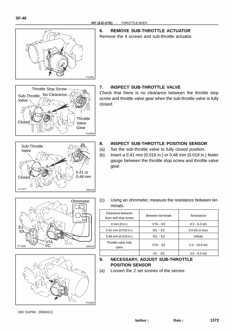
6. REMOVE SUB-THROTTLE ACTUATORRemove the 4 screws and sub-throttle actuator.
7. INSPECT SUB-THROTTLE VALVECheck that there is no clearance between the throttle stopscrew and throttle valve gear when the sub-throttle valve is fullyclosed.
8. INSPECT SUB-THROTTLE POSITION SENSOR(a) Set the sub-throttle valve to fully closed position.(b) Insert a 0.41 mm (0.016 in.) or 0.48 mm (0.019 in.) feeler
gauge between the throttle stop screw and throttle valvegear.
(c) Using an ohmmeter, measure the resistance between ter-minals.
Clearance between
lever and stop screwBetween terminals Resistance
0 mm (0 in.) VTA - E2 0.3 - 6.3 kΩ
0.41 mm (0.016 in.) IDL - E2 0.5 kΩ or less
0.48 mm (0.019 in.) IDL - E2 Infinity
Throttle valve fully
openVTA - E2 2.0 - 10.8 kΩ
- VC - E2 3.5 - 6.5 kΩ
9. NECESSARY, ADJUST SUB-THROTTLEPOSITION SENSOR
(a) Loosen the 2 set screws of the sensor.

Z09127
Sub-ThrottleValve
Closed0.45 mm
S00023
Ohmmeter
E2
IDLTurn
Z09130
Sub-ThrottleValve
0.41 or0.48 mmClosed
Ohmmeter
E2IDL
VTAVC
-SFI (2JZ-GTE) THROTTLE BODYSF-47
1373Author: Date:
1997 SUPRA (RM502U)
(b) Set the sub-throttle valve to fully closed position.(c) Insert a 0.45 mm (0.018 in.) feeler gauge, between the
throttle stop screw and throttle valve gear.
(d) Connect the tester probe of an ohmmeter to the terminalsIDL and E2 of the sensor.
(e) Gradually turn the sensor clockwise until the ohmmeterdeflects, and secure it with the 2 set screws.
(f) Recheck the continuity between terminals IDL and E2.
Clearance between
lever and stop screwContinuity (IDL - E2)
0.41 mm (0.016 in.) Continuity
0.48 mm (0.019 in.) No continuity
10. REINSTALL SUB-THROTTLE ACTUATORInstall the sub-throttle actuator with the 4 screws.

P11385
P11417
Ohmmeter
S4
S3 B1
S2B2
S1
SF0HB-01
-SFI (2JZ-GTE) IDLE AIR CONTROL (IAC) VALVESF-49
1375Author: Date:
1997 SUPRA (RM502U)
IDLE AIR CONTROL (IAC) VALVEON-VEHICLE INSPECTION1. INSPECT IAC VALVE FOR OPERATING SOUNDCheck that there is a clicking sound immediately after stoppingthe engine.If operation is not as specified, check the IAC valve, wiring andECM.2. INSPECT IAC VALVE RESISTANCENOTICE:”Cold” and ”Hot” in these sentences express the tempera-ture of the coils themselves.”Cold” is from -10 °C (14°F) to 50°C (122°F) and ”Hot” isfrom 50 °C (122°F) to 100°C (212°F).Using an ohmmeter, measure the resistance between the ter-minals (B1 (or B2) to others).
Resistance:
Cold 15 - 25 Ω
Hot 20 - 30 Ω
If resistance is not as specified, replace the IAC valve.

SF0HC-01
P18728
IAC Valve Connector
IAC Valve
Gasket
Air Hose
Water Bypass Hose
Water Bypass Hose
Non-reusable part
Seal Washer
Check Valve
SF-50-SFI (2JZ-GTE) IDLE AIR CONTROL (IAC) VALVE
1376Author: Date:
1997 SUPRA (RM502U)
COMPONENTS

SF0HD-01
P11386Connector
P11418(1)
(2)
(3)
P12820
Check Valve
SealWasher
-SFI (2JZ-GTE) IDLE AIR CONTROL (IAC) VALVESF-51
1377Author: Date:
1997 SUPRA (RM502U)
REMOVAL1. DRAIN ENGINE COOLANT2. DISCONNECT IAC VALVE CONNECTOR3. REMOVE IAC VALVE(a) Remove the 2 bolts, and disconnect the IAC valve from
the air intake chamber.(b) Remove the gasket
.
(c) Disconnect these hoses from the IAC valve, and removethe IAC valve:(1) Air hose(2) Water bypass hose (from No.2 water bypass pipe)(3) Water bypass hose (from No.4 water bypass pipe)
(d) Remove the seal washer and check valve.
SF0HE-01
P11389
Battery
Closed
B1
S1S2 B2
S3
S4
P11388
Battery
B1
S1S2 B2
S3
S4
Open
SF-52-SFI (2JZ-GTE) IDLE AIR CONTROL (IAC) VALVE
1378Author: Date:
1997 SUPRA (RM502U)
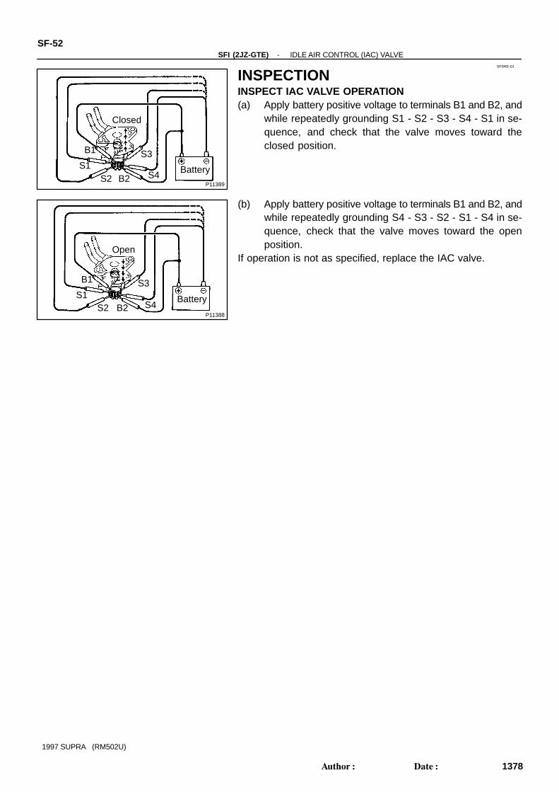
INSPECTIONINSPECT IAC VALVE OPERATION(a) Apply battery positive voltage to terminals B1 and B2, and
while repeatedly grounding S1 - S2 - S3 - S4 - S1 in se-quence, and check that the valve moves toward theclosed position.
(b) Apply battery positive voltage to terminals B1 and B2, andwhile repeatedly grounding S4 - S3 - S2 - S1 - S4 in se-quence, check that the valve moves toward the openposition.
If operation is not as specified, replace the IAC valve.
SF0HF-01
P11387
Check Valve
SealWasher
Inside
-SFI (2JZ-GTE) IDLE AIR CONTROL (IAC) VALVESF-53
1379Author: Date:
1997 SUPRA (RM502U)
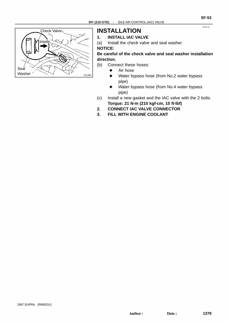
INSTALLATION1. INSTALL IAC VALVE(a) Install the check valve and seal washer.NOTICE:Be careful of the check valve and seal washer installationdirection.(b) Connect these hoses:
Air hose Water bypass hose (from No.2 water bypass
pipe) Water bypass hose (from No.4 water bypass
pipe)(c) Install a new gasket and the IAC valve with the 2 bolts.
Torque: 21 N·m (210 kgf·cm, 15 ft·lbf)2. CONNECT IAC VALVE CONNECTOR3. FILL WITH ENGINE COOLANT
P11276
EFI MainRelay
SF0HG-01
P07170
OhmmeterNo Continuity
Continuity
Ohmmeter
1
3
5
2
P07171Battery
Ohmmeter
Continuity 1
3
5
2
SF-54-SFI (2JZ-GTE) EFI MAIN RELAY
1380Author: Date:
1997 SUPRA (RM502U)
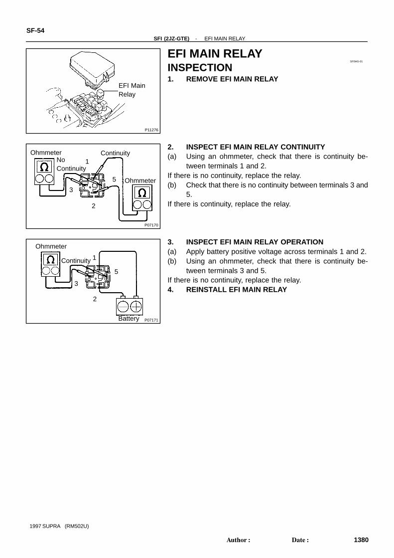
EFI MAIN RELAYINSPECTION1. REMOVE EFI MAIN RELAY
2. INSPECT EFI MAIN RELAY CONTINUITY(a) Using an ohmmeter, check that there is continuity be-
tween terminals 1 and 2.If there is no continuity, replace the relay.(b) Check that there is no continuity between terminals 3 and
5.If there is continuity, replace the relay.
3. INSPECT EFI MAIN RELAY OPERATION(a) Apply battery positive voltage across terminals 1 and 2.(b) Using an ohmmeter, check that there is continuity be-
tween terminals 3 and 5.If there is no continuity, replace the relay.4. REINSTALL EFI MAIN RELAY

P11277
EFI No.2Relay
SF0HH-01
P07170
OhmmeterNo Continuity
Continuity
Ohmmeter
1
3
5
2
P07171Battery
Ohmmeter
Continuity 1
3
5
2
-SFI (2JZ-GTE) EFI NO.2 RELAYSF-55
1381Author: Date:
1997 SUPRA (RM502U)
EFI NO.2 RELAYINSPECTION1. REMOVE EFI NO.2 RELAY
2. INSPECT EFI NO.2 RELAY CONTINUITY(a) Using an ohmmeter, check that there is continuity be-
tween terminals 1 and 2.If there is no continuity, replace the relay.(b) Check that there is no continuity between terminals 3 and
5.If there is continuity, replace the relay.
3. INSPECT EFI NO.2 RELAY OPERATION(a) Apply battery positive voltage across terminals 1 and 2.(b) Using an ohmmeter, check that there is continuity be-
tween terminals 3 and 5.If there is no continuity, replace the relay.4. REINSTALL EFI NO.2 RELAY

SF0HI-01
P11345
Solenoid ResistorAssembly
CoverSolenoid Resistor
Bracket
SolenoidResistorConnector
SF-56-SFI (2JZ-GTE) SOLENOID RESISTOR
1382Author: Date:
1997 SUPRA (RM502U)
SOLENOID RESISTORCOMPONENTS
SF0HJ-01
P11451
Ohmmeter
#20
#30
#40#50
#10
#60
+B
-SFI (2JZ-GTE) SOLENOID RESISTORSF-57
1383Author: Date:
1997 SUPRA (RM502U)
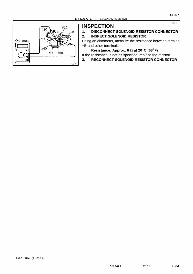
INSPECTION1. DISCONNECT SOLENOID RESISTOR CONNECTOR2. INSPECT SOLENOID RESISTORUsing an ohmmeter, measure the resistance between terminal+B and other terminals.
Resistance: Approx. 6 Ω at 20°C (68°F)If the resistance is not as specified, replace the resistor.3. RECONNECT SOLENOID RESISTOR CONNECTOR

SF0HK-01
P11478
Vacuum Sensing Hose
VSV
VSV Connector
Vacuum Sensing Hose
SF-58-SFI (2JZ-GTE) VSV FOR FUEL PRESSURE CONTROL
1384Author: Date:
1997 SUPRA (RM502U)
VSV FOR FUEL PRESSURE CONTROLCOMPONENTS

SF0HL-01
P11340
Ohmmeter
Continuity
P11341
Ohmmeter
No Continuity
P11342
Air
E
G
P11343
Air
E
Filter
Battery
-SFI (2JZ-GTE) VSV FOR FUEL PRESSURE CONTROLSF-59
1385Author: Date:
1997 SUPRA (RM502U)
INSPECTION1. REMOVE VSV2. INSPECT VSV FOR OPEN CIRCUITUsing an ohmmeter, check that there is continuity between theterminals.
Resistance: 33 - 39 Ω at 20°C (68°F)If there is no continuity, replace the VSV.
3. INSPECT VSV FOR GROUNDUsing an ohmmeter, check that there is no continuity betweeneach terminal and the body.If there is continuity, replace the VSV.
4. INSPECT VSV OPERATION(a) Check that air flows from port E to G.
(b) Apply battery positive voltage across the terminals.(c) Check that air flows from port E to the filter.If operation is not as specified, replace the VSV.5. REINSTALL VSV

SF0HM-01
P11421
Air HoseVSV Connector
VSV
SF-60-SFI (2JZ-GTE) VSV FOR INTAKE AIR CONTROL VALVE
1386Author: Date:
1997 SUPRA (RM502U)
VSV FOR INTAKE AIR CONTROL VALVECOMPONENTS
SF0HN-01
P11371
Ohmmeter
Continuity
P11372
Ohmmeter
No Continuity
P11414
Air
E
Filter
P11373
Air
E Battery
F
-SFI (2JZ-GTE) VSV FOR INTAKE AIR CONTROL VALVESF-61
1387Author: Date:
1997 SUPRA (RM502U)
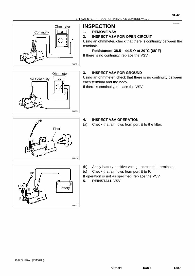
INSPECTION1. REMOVE VSV2. INSPECT VSV FOR OPEN CIRCUITUsing an ohmmeter, check that there is continuity between theterminals.
Resistance: 38.5 - 44.5 Ω at 20°C (68°F)If there is no continuity, replace the VSV.
3. INSPECT VSV FOR GROUNDUsing an ohmmeter, check that there is no continuity betweeneach terminal and the body.If there is continuity, replace the VSV.
4. INSPECT VSV OPERATION(a) Check that air flows from port E to the filter.
(b) Apply battery positive voltage across the terminals.(c) Check that air flows from port E to F.If operation is not as specified, replace the VSV.5. REINSTALL VSV

SF0HO-01
P11346
No.1 Air Hose
Engine Wire
VSV Assembly
Air Hose
Air Hose
VSV Connectorfor Waste GateValve
VSV Connectorfor Exhaust GasControl Valve
Bracket andVSV for ExhaustGas Control Valve
VSV for WasteGate Valve
SF-62-SFI (2JZ-GTE) VSV FOR WASTE GATE VALVE
1388Author: Date:
1997 SUPRA (RM502U)
VSV FOR WASTE GATE VALVECOMPONENTS

SF0HP-01
P11378
Continuity Ohmmeter
P11379
No Continuity Ohmmeter
P11380
Air
EF
P11381
Air
EF
Battery
-SFI (2JZ-GTE) VSV FOR WASTE GATE VALVESF-63
1389Author: Date:
1997 SUPRA (RM502U)
INSPECTION1. REMOVE VSV ASSEMBLY2. INSPECT VSV FOR OPEN CIRCUITUsing an ohmmeter, check that there is continuity between theterminals.
Resistance: 22 - 26 Ω at 20°C (68°F)If there is no continuity, replace the VSV.
3. INSPECT VSV FOR GROUNDUsing an ohmmeter, check that there is no continuity betweeneach terminal and the body.If there is continuity, replace the VSV.
4. INSPECT VSV OPERATION(a) Check that air does not flow from port E to F.
(b) Apply battery positive voltage across the terminals.(c) Check that air flows from port E to F.If operation is not as specified, replace the VSV.5. REINSTALL VSV ASSEMBLY
SF0HQ-01
P11347
No.1 Air Hose
Engine Wire
VSV Assembly
Air HoseAir Hose
Bracket andVSV for WasteGate Valve
VSV for ExhaustGas Control Valve
VSV Connectorfor Exhaust GasControl Valve
VSV Connectorfor Waste GateValve
SF-64-SFI (2JZ-GTE) VSV FOR EXHAUST GAS CONTROL VALVE
1390Author: Date:
1997 SUPRA (RM502U)
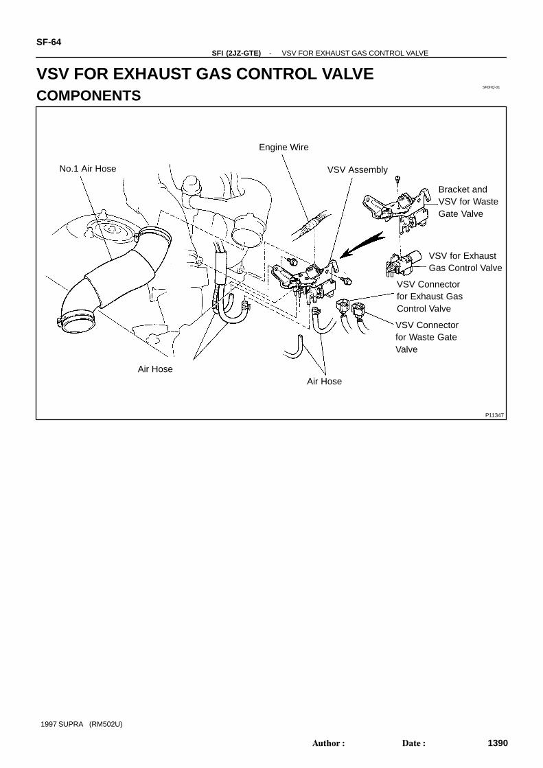
VSV FOR EXHAUST GAS CONTROL VALVECOMPONENTS

SF0HR-01
P11382
ContinuityOhmmeter
P11383
No Continuity
Ohmmeter
P11415
Filter
Air
E
P11384
F
Air
E Battery
-SFI (2JZ-GTE) VSV FOR EXHAUST GAS CONTROL VALVESF-65
1391Author: Date:
1997 SUPRA (RM502U)
INSPECTION1. REMOVE VSV ASSEMBLY2. INSPECT VSV FOR OPEN CIRCUITUsing an ohmmeter, check that there is continuity between theterminals.
Resistance: 38.5 - 44.5 Ω at 20°C (68°F)If there is no continuity, replace the VSV.
3. INSPECT VSV FOR GROUNDUsing an ohmmeter, check that there is no continuity betweeneach terminal and the body.If there is continuity, replace the VSV.
4. INSPECT VSV OPERATION(a) Check that air flows from port E to the filter.
(b) Apply battery positive voltage across the terminals.(c) Check that air flows from port E to F.If operation is not as specified, replace the VSV.5. REINSTALL VSV ASSEMBLY
SF0HS-01
P11480
Air Hose
VSV
Control Cable Clamp
VSV Connector
SF-66-SFI (2JZ-GTE) VSV FOR EXHAUST BY-PASS VALVE
1392Author: Date:
1997 SUPRA (RM502U)
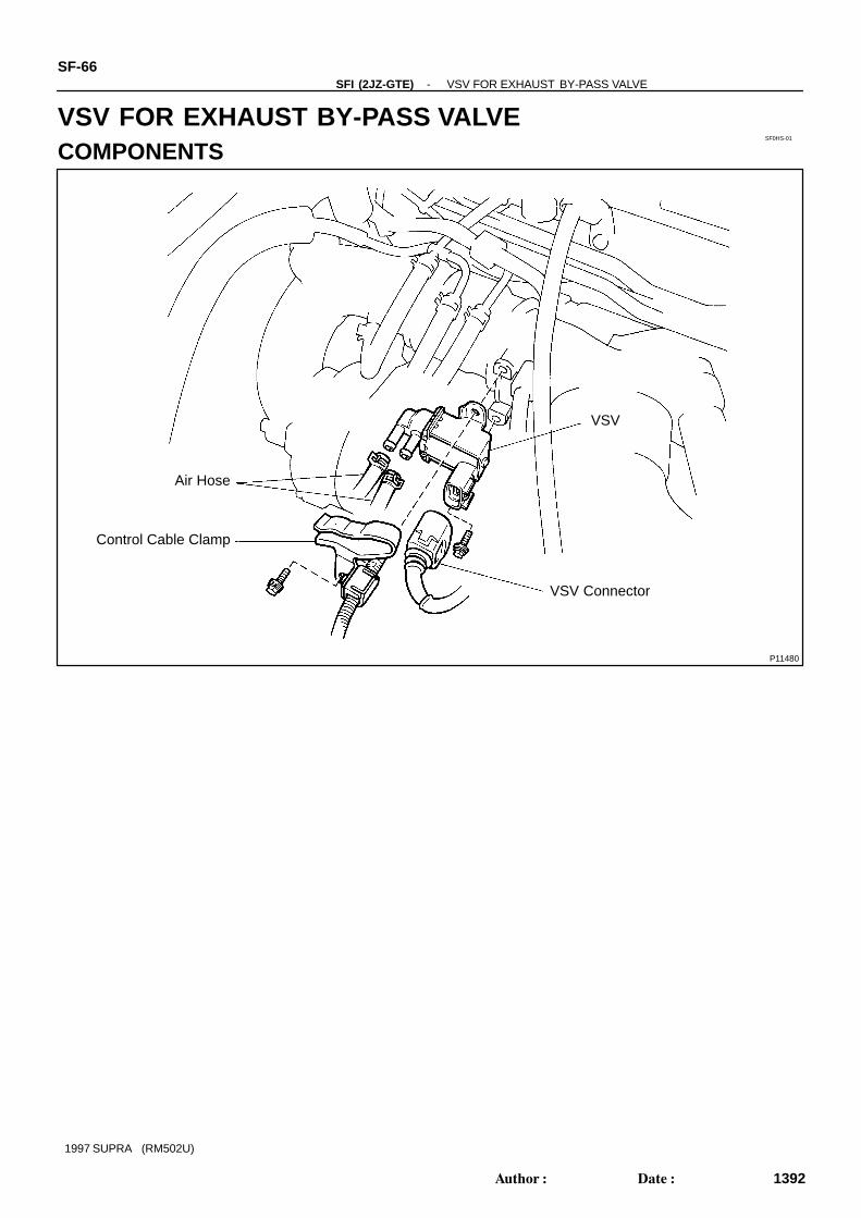
VSV FOR EXHAUST BY-PASS VALVECOMPONENTS
SF0HT-01
P11374
Continuity Ohmmeter
P11375
No Continuity Ohmmeter
P11376
Air
E
F
P11377
Air
EF
Battery
-SFI (2JZ-GTE) VSV FOR EXHAUST BY-PASS VALVESF-67
1393Author: Date:
1997 SUPRA (RM502U)
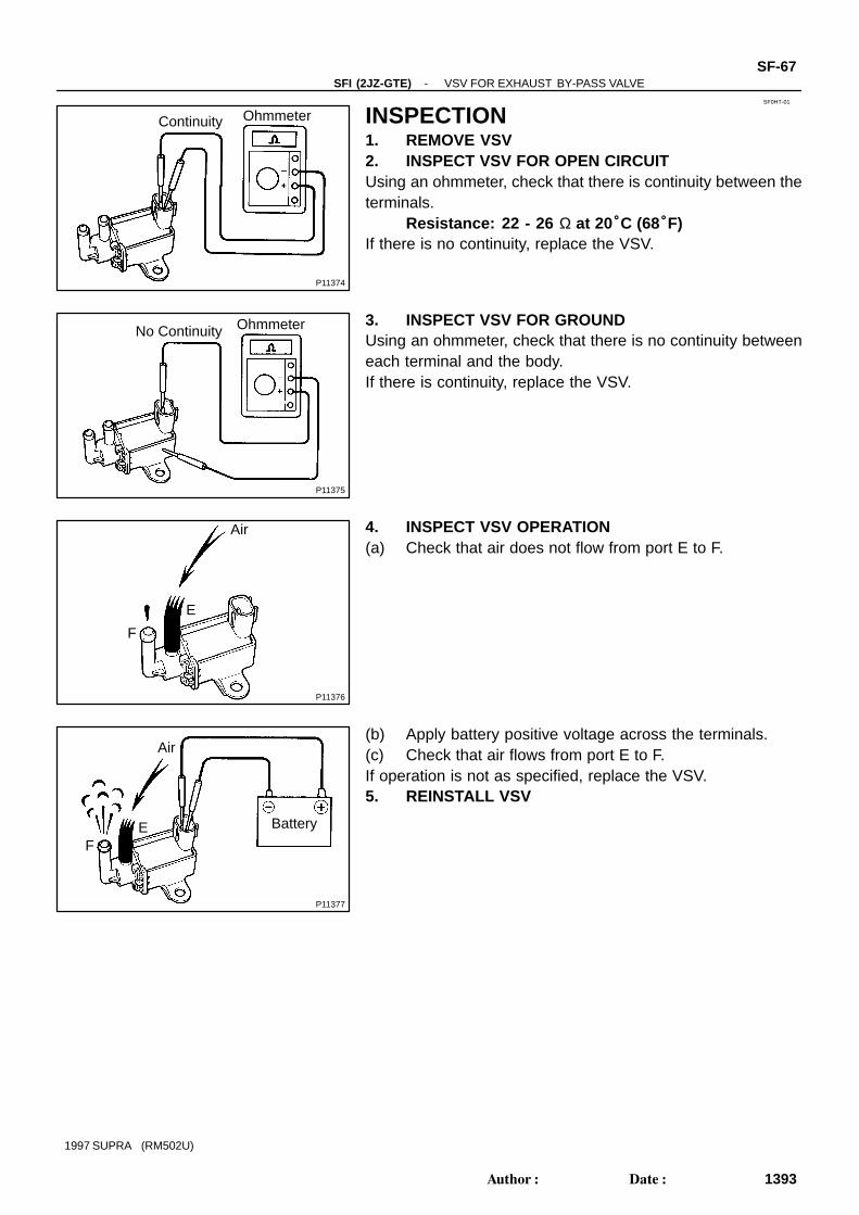
INSPECTION1. REMOVE VSV2. INSPECT VSV FOR OPEN CIRCUITUsing an ohmmeter, check that there is continuity between theterminals.
Resistance: 22 - 26 Ω at 20°C (68°F)If there is no continuity, replace the VSV.
3. INSPECT VSV FOR GROUNDUsing an ohmmeter, check that there is no continuity betweeneach terminal and the body.If there is continuity, replace the VSV.
4. INSPECT VSV OPERATION(a) Check that air does not flow from port E to F.
(b) Apply battery positive voltage across the terminals.(c) Check that air flows from port E to F.If operation is not as specified, replace the VSV.5. REINSTALL VSV
SF0I2-01
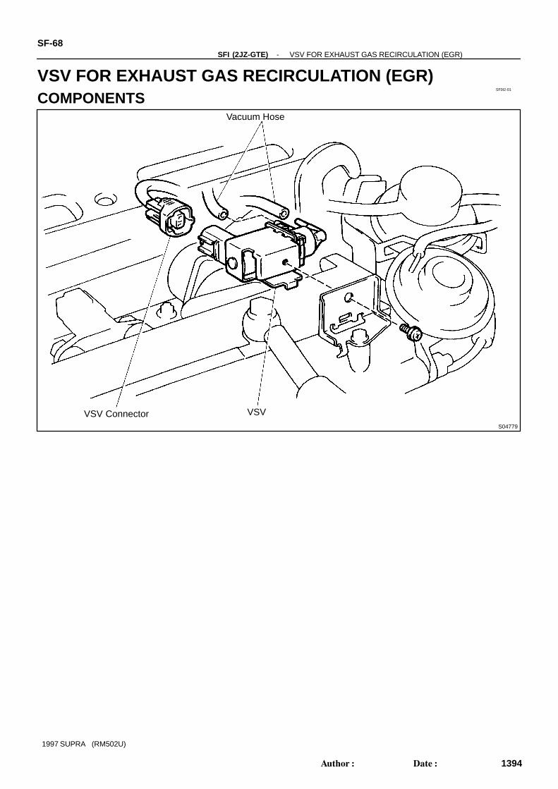
S04779
Vacuum Hose
VSV Connector VSV
SF-68-SFI (2JZ-GTE) VSV FOR EXHAUST GAS RECIRCULATION (EGR)
1394Author: Date:
1997 SUPRA (RM502U)
VSV FOR EXHAUST GAS RECIRCULATION (EGR)COMPONENTS
SF0I3-01
P11360
Ohmmeter
Continuity
P11361
Ohmmeter
No Continuity
P11362
Air
E
F
P11363
Air
E
F
Battery
-SFI (2JZ-GTE) VSV FOR EXHAUST GAS RECIRCULATION (EGR)SF-69
1395Author: Date:
1997 SUPRA (RM502U)
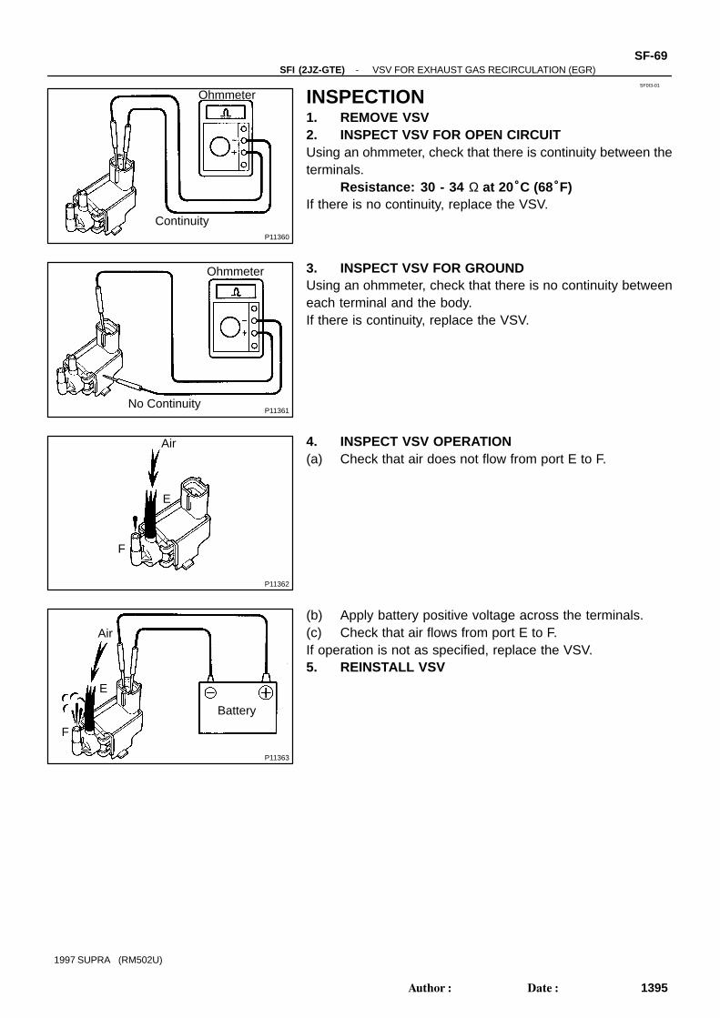
INSPECTION1. REMOVE VSV2. INSPECT VSV FOR OPEN CIRCUITUsing an ohmmeter, check that there is continuity between theterminals.
Resistance: 30 - 34 Ω at 20°C (68°F)If there is no continuity, replace the VSV.
3. INSPECT VSV FOR GROUNDUsing an ohmmeter, check that there is no continuity betweeneach terminal and the body.If there is continuity, replace the VSV.
4. INSPECT VSV OPERATION(a) Check that air does not flow from port E to F.
(b) Apply battery positive voltage across the terminals.(c) Check that air flows from port E to F.If operation is not as specified, replace the VSV.5. REINSTALL VSV
SF0HX-01
P11407
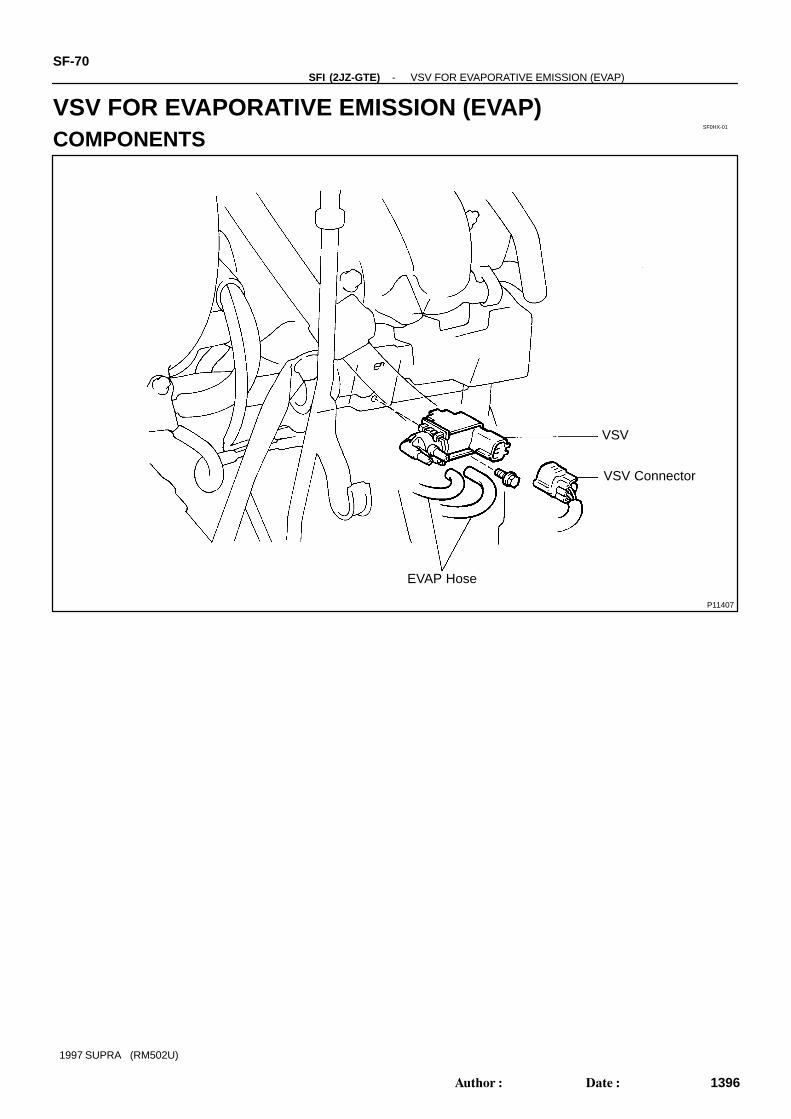
VSV
VSV Connector
EVAP Hose
SF-70-SFI (2JZ-GTE) VSV FOR EVAPORATIVE EMISSION (EVAP)
1396Author: Date:
1997 SUPRA (RM502U)
VSV FOR EVAPORATIVE EMISSION (EVAP)COMPONENTS
P11456
Ohmmeter
Continuity
SF0HW-01
P11457
Ohmmeter
No Continuity
P11458
Air
EF
P11459
Air
EF
Battery
-SFI (2JZ-GTE) VSV FOR EVAPORATIVE EMISSION (EVAP)SF-71
1397Author: Date:
1997 SUPRA (RM502U)
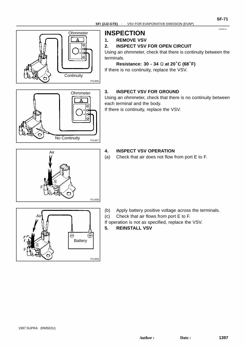
INSPECTION1. REMOVE VSV2. INSPECT VSV FOR OPEN CIRCUITUsing an ohmmeter, check that there is continuity between theterminals.
Resistance: 30 - 34 Ω at 20°C (68°F)If there is no continuity, replace the VSV.
3. INSPECT VSV FOR GROUNDUsing an ohmmeter, check that there is no continuity betweeneach terminal and the body.If there is continuity, replace the VSV.
4. INSPECT VSV OPERATION(a) Check that air does not flow from port E to F.
(b) Apply battery positive voltage across the terminals.(c) Check that air flows from port E to F.If operation is not as specified, replace the VSV.5. REINSTALL VSV
SF0HY-01
P11477
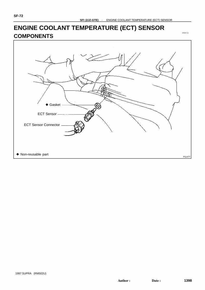
Gasket
ECT Sensor
ECT Sensor Connector
Non-reusable part
SF-72-SFI (2JZ-GTE) ENGINE COOLANT TEMPERATURE (ECT) SENSOR
1398Author: Date:
1997 SUPRA (RM502U)
ENGINE COOLANT TEMPERATURE (ECT) SENSORCOMPONENTS

SF0HZ-01
P11473
SST
Z02917
Ohmmeter
Acceptable
TEMPERATURE °C(°F)
RE
SIS
TAN
CE
κΩ
-SFI (2JZ-GTE) ENGINE COOLANT TEMPERATURE (ECT) SENSORSF-73
1399Author: Date:
1997 SUPRA (RM502U)
INSPECTION1. DRAIN ENGINE COOLANT2. REMOVE ECT SENSOR(a) Disconnect the ECT sensor connector.(b) Using SST, remove the ECT sensor and gasket.
SST 09205-76030
3. INSPECT ECT SENSORUsing an ohmmeter, measure the resistance between the ter-minals.
Resistance: Refer to the graphIf the resistance is not as specified, replace the ECT sensor.4. REINSTALL ECT SENSOR(a) Install a new gasket to the ECT sensor.(b) Using SST, install the ECT sensor.
SST 09205-76030(c) Connect the ECT sensor connector.5. REFILL WITH ENGINE COOLANT
SF0I0-01
Z13774
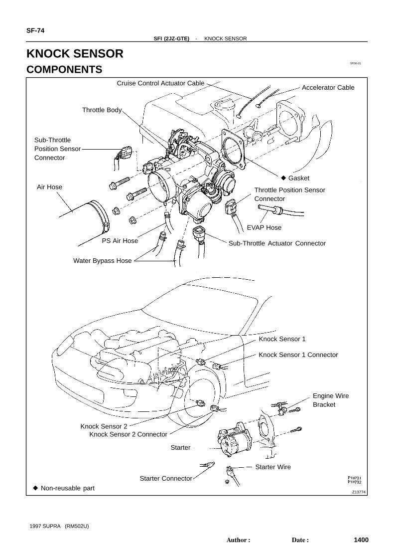
Cruise Control Actuator CableAccelerator Cable
Throttle Body
Sub-ThrottlePosition SensorConnector
Air Hose Gasket
Throttle Position SensorConnector
EVAP Hose
Sub-Throttle Actuator Connector
Water Bypass Hose
Knock Sensor 1
Engine WireBracket
Starter
Starter Connector
Non-reusable part
Starter Wire
PS Air Hose
Knock Sensor 1 Connector
Knock Sensor 2Knock Sensor 2 Connector
SF-74-SFI (2JZ-GTE) KNOCK SENSOR
1400Author: Date:
1997 SUPRA (RM502U)
KNOCK SENSORCOMPONENTS
SF0I1-01
P12819
SST
P01630
Ohmmeter
-SFI (2JZ-GTE) KNOCK SENSORSF-75
1401Author: Date:
1997 SUPRA (RM502U)
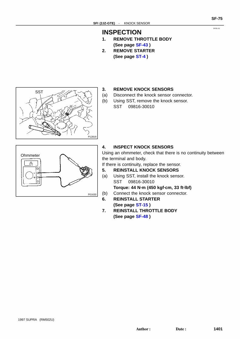
INSPECTION1. REMOVE THROTTLE BODY
(See page SF-43 )2. REMOVE STARTER
(See page ST-4 )
3. REMOVE KNOCK SENSORS(a) Disconnect the knock sensor connector.(b) Using SST, remove the knock sensor.
SST 09816-30010
4. INSPECT KNOCK SENSORSUsing an ohmmeter, check that there is no continuity betweenthe terminal and body.If there is continuity, replace the sensor.5. REINSTALL KNOCK SENSORS(a) Using SST, install the knock sensor.
SST 09816-30010Torque: 44 N·m (450 kgf·cm, 33 ft·lbf)
(b) Connect the knock sensor connector.6. REINSTALL STARTER
(See page ST-15 )7. REINSTALL THROTTLE BODY
(See page SF-48 )
SF0HU-01
S03269
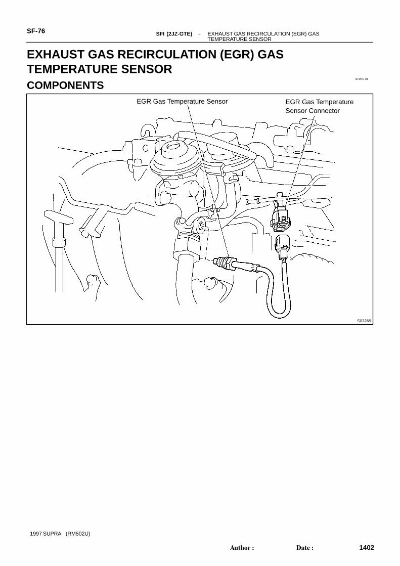
EGR Gas Temperature Sensor EGR Gas TemperatureSensor Connector
SF-76 -SFI (2JZ-GTE) EXHAUST GAS RECIRCULATION (EGR) GAS TEMPERATURE SENSOR
1402Author: Date:
1997 SUPRA (RM502U)
EXHAUST GAS RECIRCULATION (EGR) GASTEMPERATURE SENSORCOMPONENTS
SF0HV-01
P03193
Oil
-SFI (2JZ-GTE) EXHAUST GAS RECIRCULATION (EGR) GAS TEMPERATURE SENSOR
SF-77
1403Author: Date:
1997 SUPRA (RM502U)
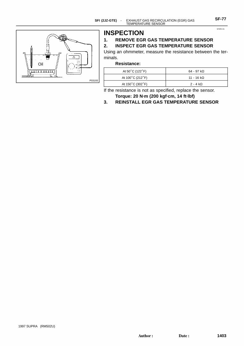
INSPECTION1. REMOVE EGR GAS TEMPERATURE SENSOR2. INSPECT EGR GAS TEMPERATURE SENSORUsing an ohmmeter, measure the resistance between the ter-minals.
Resistance:
At 50°C (122°F) 64 - 97 kΩ
At 100°C (212°F) 11 - 16 kΩ
At 150°C (302°F) 2 - 4 kΩ
If the resistance is not as specified, replace the sensor.Torque: 20 N·m (200 kgf·cm, 14 ft·lbf)
3. REINSTALL EGR GAS TEMPERATURE SENSOR
SF0I4-01
P11410
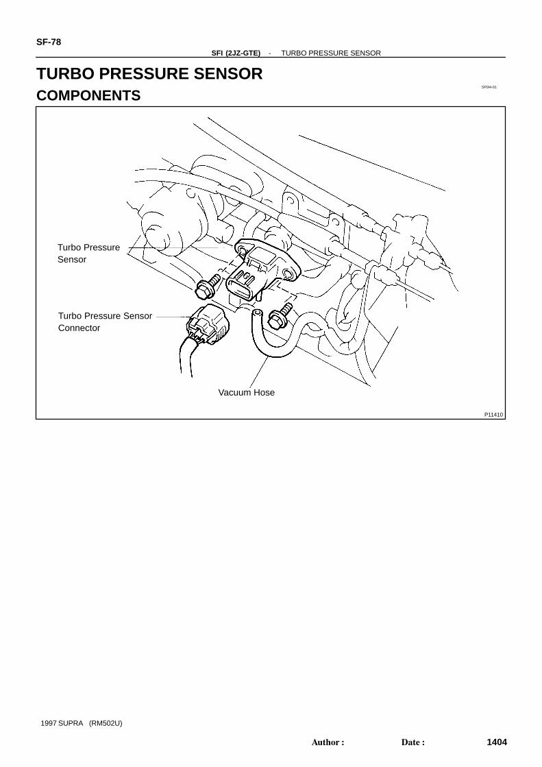
Turbo PressureSensor
Turbo Pressure SensorConnector
Vacuum Hose
SF-78-SFI (2JZ-GTE) TURBO PRESSURE SENSOR
1404Author: Date:
1997 SUPRA (RM502U)
TURBO PRESSURE SENSORCOMPONENTS
SF0I5-01
P11390
Disconnect
P11419
Voltmeter
E2
VC
P11984
P12022
Disconnect
-SFI (2JZ-GTE) TURBO PRESSURE SENSORSF-79
1405Author: Date:
1997 SUPRA (RM502U)
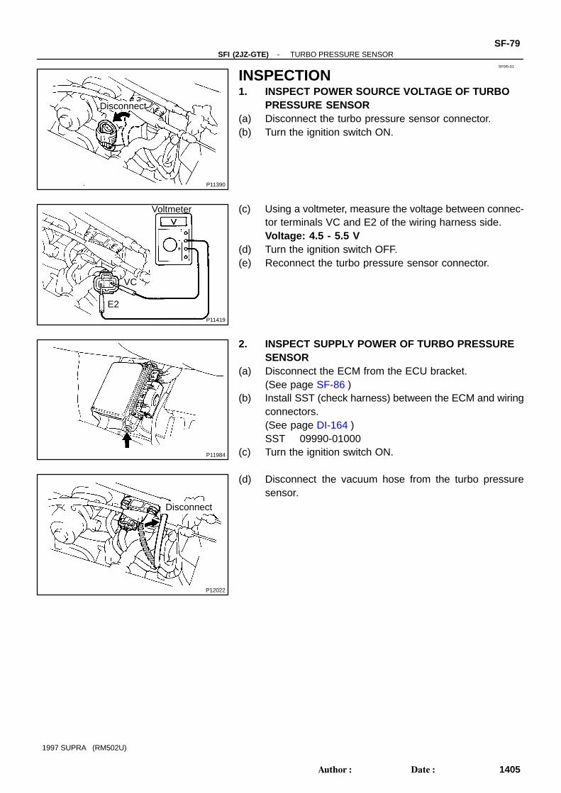
INSPECTION1. INSPECT POWER SOURCE VOLTAGE OF TURBO
PRESSURE SENSOR(a) Disconnect the turbo pressure sensor connector.(b) Turn the ignition switch ON.
(c) Using a voltmeter, measure the voltage between connec-tor terminals VC and E2 of the wiring harness side.Voltage: 4.5 - 5.5 V
(d) Turn the ignition switch OFF.(e) Reconnect the turbo pressure sensor connector.
2. INSPECT SUPPLY POWER OF TURBO PRESSURESENSOR
(a) Disconnect the ECM from the ECU bracket.(See page SF-86 )
(b) Install SST (check harness) between the ECM and wiringconnectors.(See page DI-164 )SST 09990-01000
(c) Turn the ignition switch ON.
(d) Disconnect the vacuum hose from the turbo pressuresensor.

Z09082
Voltmeter
Vacuum
E2 PIM
SSTECM
AppliedVacuum
kPammHgin. Hg.
Voltagedrop V
13.31003.94
26.7 40.0 53.3 66.72007.87
30011.81
40015.75
50019.69
0.15 -0.35
0.4 -0.6
0.65 -0.85
0.9 -1.1
1.15 -1.35
P11986
Insert
SF-80-SFI (2JZ-GTE) TURBO PRESSURE SENSOR
1406Author: Date:
1997 SUPRA (RM502U)
(e) Connect a voltmeter to terminals PIM and E2 of the ECM,and measure the output voltage under ambient atmo-spheric pressure.
(f) Apply vacuum to the turbo pressure sensor in 13.3 kPa(100 mmHg, 3.94 in.Hg) segments to 66.7 kPa (500mmHg, 19.69 in.Hg).
(g) Measure the voltage drop from step (c) above for eachsegment.Voltage drop:
(h) Remove the SST.SST 09990-01000
(i) Reinstall the ECM. (See page SF-86 )(j) Reconnect the vacuum hose to the turbo pressure sen-
sor.
SF0I6-01
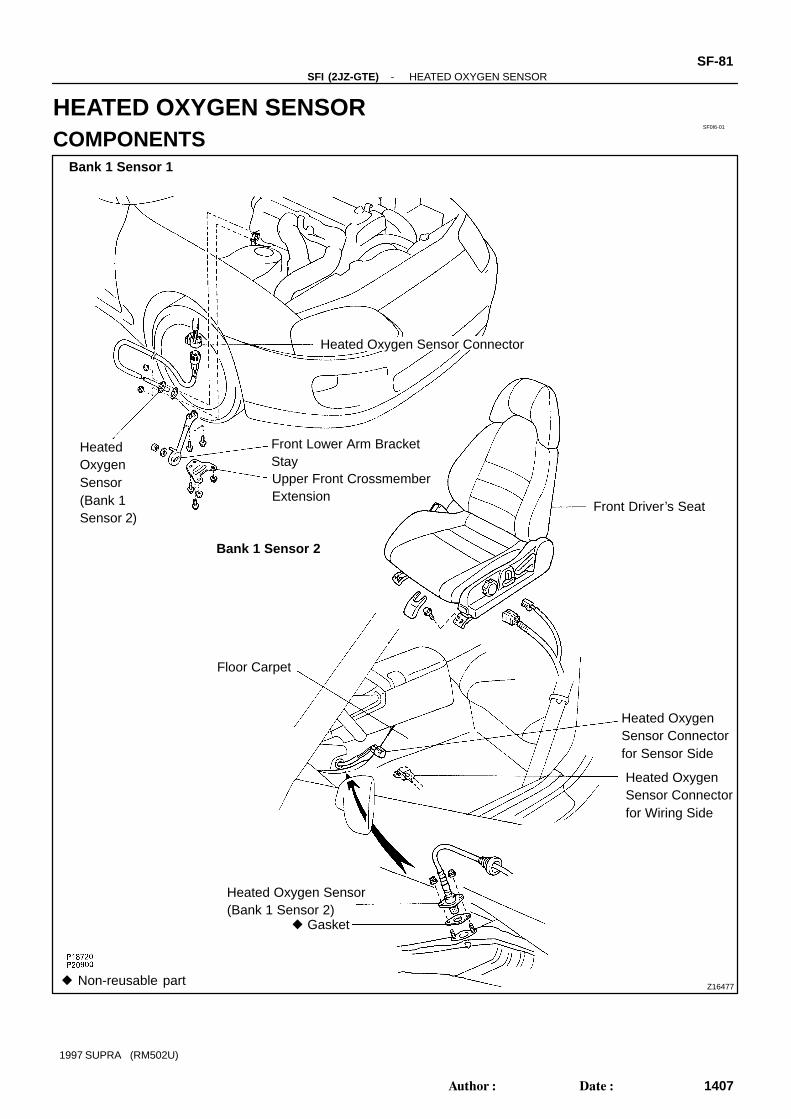
Z16477
Heated Oxygen Sensor Connector
Front Lower Arm BracketStayUpper Front CrossmemberExtension
HeatedOxygenSensor(Bank 1Sensor 2)
Front Driver’s Seat
Floor Carpet
Heated OxygenSensor Connectorfor Sensor Side
Heated OxygenSensor Connectorfor Wiring Side
Heated Oxygen Sensor(Bank 1 Sensor 2)
Gasket
Bank 1 Sensor 2
Bank 1 Sensor 1
Non-reusable part
-SFI (2JZ-GTE) HEATED OXYGEN SENSORSF-81
1407Author: Date:
1997 SUPRA (RM502U)
HEATED OXYGEN SENSORCOMPONENTS
SF0I7-01
P11993
Ohmmeter
+B HT
Bank 1 Sensor 1
P11483
Ohmmeter
+B
HT
Bank 1 Sensor 2
SF-82-SFI (2JZ-GTE) HEATED OXYGEN SENSOR
1408Author: Date:
1997 SUPRA (RM502U)
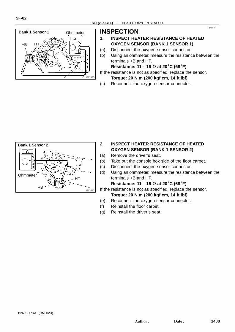
INSPECTION1. INSPECT HEATER RESISTANCE OF HEATED
OXYGEN SENSOR (BANK 1 SENSOR 1)(a) Disconnect the oxygen sensor connector.(b) Using an ohmmeter, measure the resistance between the
terminals +B and HT.Resistance: 11 - 16 Ω at 20°C (68°F)
If the resistance is not as specified, replace the sensor.Torque: 20 N·m (200 kgf·cm, 14 ft·lbf)
(c) Reconnect the oxygen sensor connector.
2. INSPECT HEATER RESISTANCE OF HEATEDOXYGEN SENSOR (BANK 1 SENSOR 2)
(a) Remove the driver’s seat.(b) Take out the console box side of the floor carpet.(c) Disconnect the oxygen sensor connector.(d) Using an ohmmeter, measure the resistance between the
terminals +B and HT.Resistance: 11 - 16 Ω at 20°C (68°F)
If the resistance is not as specified, replace the sensor.Torque: 20 N·m (200 kgf·cm, 14 ft·lbf)
(e) Reconnect the oxygen sensor connector.(f) Reinstall the floor carpet.(g) Reinstall the driver’s seat.

SF0I8-01
P20904
Fuel Pump ECU
Fuel Pump ECUConnector
RH Deck TrimSide Board
Rear Deck Trim Cover
Inner QuarterWheel Hose Cover
Stay Support Cover
Removal Roof Stay
Service Hole Cover
Floor Carpetx4
x3
-SFI (2JZ-GTE) FUEL PUMP ECUSF-83
1409Author: Date:
1997 SUPRA (RM502U)
FUEL PUMP ECUCOMPONENTS
SF0IA-01
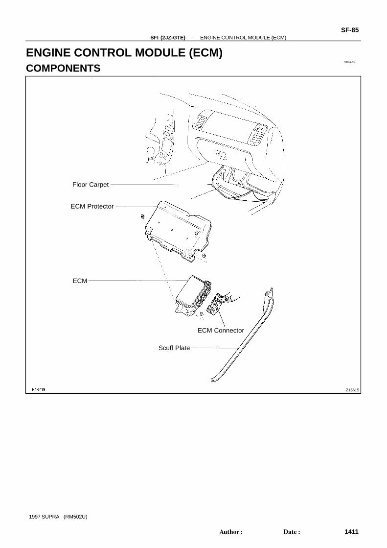
Z16615
Floor Carpet
ECM Protector
ECM
ECM Connector
Scuff Plate
-SFI (2JZ-GTE) ENGINE CONTROL MODULE (ECM)SF-85
1411Author: Date:
1997 SUPRA (RM502U)
ENGINE CONTROL MODULE (ECM)COMPONENTS

SF0IB-01
P11983
P11985
Bolt
Z06725
(Before Connection) (After Connection)
ConnectorBoltCollarStopper
Less than 1 mm
Female
Nut
MaleConnector
P11986
Insert
SF-86-SFI (2JZ-GTE) ENGINE CONTROL MODULE (ECM)
1412Author: Date:
1997 SUPRA (RM502U)
INSPECTION1. DISCONNECT NEGATIVE (-) TERMINAL CABLE
FROM BATTERY2. REMOVE SCUFF PLATE3. REMOVE ECM PROTECTOR(a) Take out the front side of the floor carpet.(b) Remove the 2 nuts and ECM protector.
4. REMOVE ECM(a) Remove the nut, and disconnect the ECM from the floor
panel.(b) Fully loosen the bolt and disconnect the 2 ECM connec-
tors, and remove the ECM.5. INSPECT ECM
(See page DI-164 )
6. REINSTALL ECM(a) Connect the 2 ECM connectors.
Match the male connector correctly with the femaleconnector, then press them together.
Tighten the bolt.Make sure the connector is completely connectedby tightening the bolt until there is a clearance ofless than 1 mm (0.04 in.) between the bottom of themale connector and the end of the female connec-tor.
(b) Install the ECM with the nut.7. REINSTALL ECM PROTECTOR8. REINSTALL SCUFF PLATE9. RECONNECT NEGATIVE (-) TERMINAL CABLE TO
BATTERY
SF0IC-02
Q08242
TOYOTA Hand-Held Tester
DLC3
P11358Sound Scope
-SFI (2JZ-GTE) FUEL CUT RPMSF-87
1413Author: Date:
1997 SUPRA (RM502U)
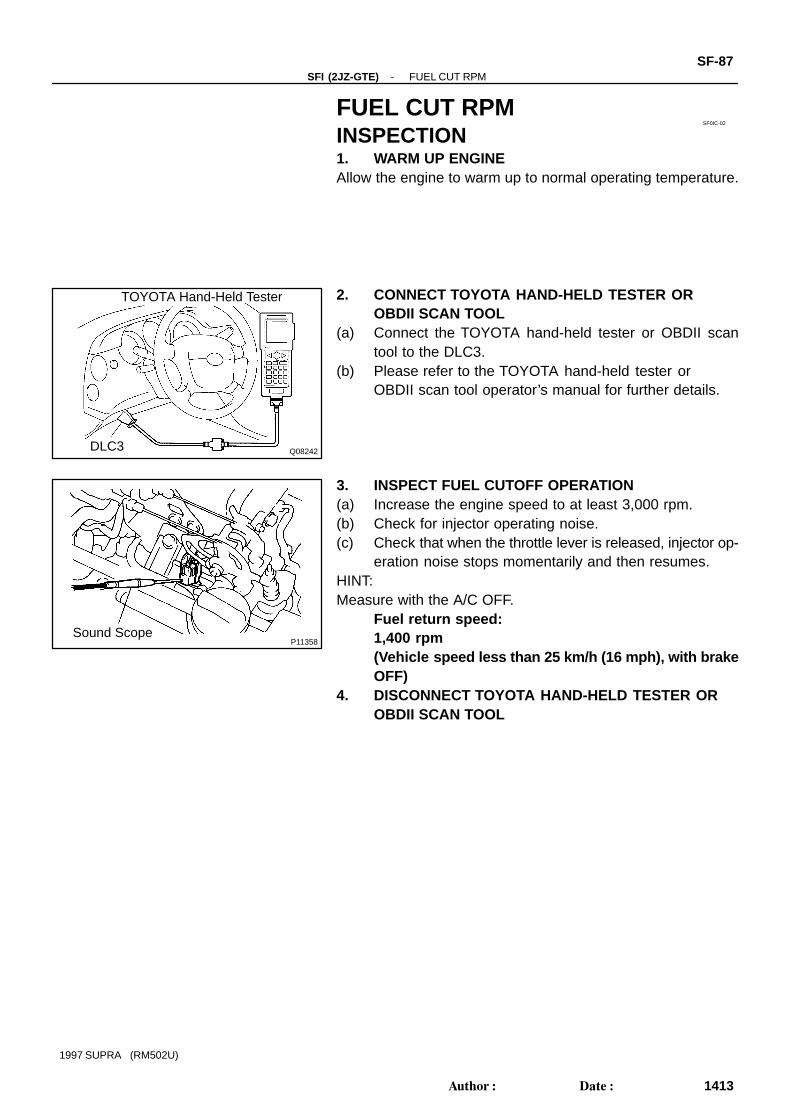
FUEL CUT RPMINSPECTION1. WARM UP ENGINEAllow the engine to warm up to normal operating temperature.
2. CONNECT TOYOTA HAND-HELD TESTER OROBDII SCAN TOOL
(a) Connect the TOYOTA hand-held tester or OBDII scantool to the DLC3.
(b) Please refer to the TOYOTA hand-held tester orOBDII scan tool operator’s manual for further details.
3. INSPECT FUEL CUTOFF OPERATION(a) Increase the engine speed to at least 3,000 rpm.(b) Check for injector operating noise.(c) Check that when the throttle lever is released, injector op-
eration noise stops momentarily and then resumes.HINT:Measure with the A/C OFF.
Fuel return speed:1,400 rpm(Vehicle speed less than 25 km/h (16 mph), with brakeOFF)
4. DISCONNECT TOYOTA HAND-HELD TESTER OROBDII SCAN TOOL