09/09/2003, westinghouse electric co., use of mnsa-2 as
TRANSCRIPT

Use of MNSA-2 as a Contingency Repairfor BMI Nozzles
Westinghouse Electric Company
September 9, 2003
BNFL Slide 1 Westinghouse
GBNFL Slide I OWestinghouse

Meeting Agenda
* Purpose of Meeting
* MNSA Overview & Mock-up Demonstration
* Experience
* MNSA-2 Design
* Qualification of MNSA-2 Assembly and theRPV lower head
* Preliminary Risk Analysis
* Relief Request Overview
* Wrap-up
Slide 2 Westinghouse
AIM6
QjBNFL Slide 2 aftsfinghouse
I .
Purpose
* Several plants are considering the use of MNSA-2as a contingency for RPV bottom mounted nozzle(IMI/BMI) repairs
* Provide summary information relating to thetechnical suitability and adequacy of this repair forapplication to BMI nozzles
* Receive Staff feedback concerning use of MNSAon BMI nozzles
BNFL WSlie3 (OWestinghouse

MNSA OVERVIEW
* The MNSA (Mechanical Nozzle Seal Assembly)is a mechanical device that provides both sealingand structural support for nozzle connections.
* MNSA has been accepted and installed on nozzlesin the CE fleet (Hot Legs, Pressurizers and SteamGenerators)
* Previous nozzle sizes bound that of BMI's
* Design and qualification test reports were submittedto the NRC in support of MNSA installation
OBNFL Slide4 Westinghouse

A ,
MNSA OVERVIEW
* There are two types of MNSAs* MNSA-1 seals on the outside of the pressure
boundary* MNSA-2 seals on the flat surface at the
bottom of the counterbore
* MNSA is an alternative to weld repair for leaks inJ-groove welded Alloy 600 instrument nozzles.
* MNSA-2 will be employed in the BMI application
IBNFL Slide 5 (SWesfinghouse

4.
MNSA OVERVIEW* MNSA has been designed and qualified as a permanent
repair for an ASME Section 111, Classl pressureboundary for the life of the plant.
MNSA is a repair which can be visually inspected fromthe vessel O.D.
* Vessel wastage U.T. inspections can be made withMNSA in place
* MNSA will not interfere with future volumetric NDE of theBMI nozzles
* NRC has accepted MNSA repairs for at least 2 fuelcycles
(BNFL Slide 6 (SWestinghouse

Technical Considerations for Utilization ofthe MNSA Contingency
* MNSA Strengths:- No breach of the pressure boundary required for
installation- Lower Radiological Dose for installation- Does not require cutting, disposal and replacement of in-
core instrumentation- Design accommodates wastage inspection from reactor
vessel outside surface- Visual examination of the leak off tube can be performed
at subsequent outages to confirm primary seal integrity- Not a new method - successfully used in primary system
pressure boundary applications (ASME Ill Class 1)- The anti-ejection feature provides a second barrier to
nozzle ejection and the potential for a LOCA@DBNFL Slide 7 ()Westinghouse

MNSA-2 Mock-up Demonstration
Ti
Inboard/IFla
Channel
Compress.
BNFL Slide 8 *Westinghouse
C-OI

MNSA Experience Summary
I ______ INSTALLED MNSAS
.._ _ _ _ ._ _ _ _ _ _ _ _ _ _ ...-. 1Plant Name # installed Location When installed When removed
IMaine Yankee 1 Pzr RTD nozzle 1995 Plant shut down'SONGS 2 2 Lower Pzr Hd Feb-98 Still on
ISONGS 2 2 Hot Leg RTD Feb-98 Jan-99ISONGS 2 2 Stm Gen PDT Feb-98 Still onSONGS 3 I 1 Side Pzr RTD Mar-98 Still onSONGS 3 2 Lower Pzr Hd Mar-98 Still on
-.. ... ... _ _ _ . .~ ~ ~~~~~~~~~~~~~~~~~~~~~~~~~~~~~~~~~~~~~~~~~~~~~~~~~~~~~~~~~~~~~~~~~~~~~~~~~~~~~~~~~~~~~~~~~~~~~~~~~~~~~~~~~~ _ _ _ _ _ _S i l oCalvert Cliffs 1 1 Side Pzr RTD Mar_0 Still onCalvert Cliffs 1 2 Lower Pzr Hd Mar-00 Still onCalvert Cliffs 1 4 Upper Pzr Head Mar-00 Still onCalvert Cliffs 2 1 Side Pzr RTD Mar-01 still on
iCalvert Cliffs 2 2 Lower Pzr Hd Mar-01 Still on.IPalo Verde 3 I Hot Leg RTD Oct-01 I Apr-03Palo Verde 2 Pzr Htr SlM Apr-03 Still onMillstone 2 2 Pzr Htr Sly Feb-02 Still on -
_ _ _ _ _ _ _ _ _ .. . ,
AN02(MNSA2) 6 Pzr Htr Slv Mar-02 Still on
Fort Calhoun - Upper Pzr Head Oct-00 Feb-03 Iaterford 3 3 Hot Leg Inst Noz Mar-99 Oct-00
BNFL Slie 9 G Wetinghousldmh�
""LBNFLqu Slide 9 OWesfinghouse

MNSA-1 Design
* Grafoil seats against nozzleOD and vessel OD
:~~~~~~~~~~~~~~
* 4 bolts load compressionring
* Belleville Washers
* Tie Rods prevent ejection ifloss of weld
Top Plate
CompressionRing (Split) -
Retaining Ring -(Split)
Load Ring -
Base Plate -
- Tie Rod
4, 1/2 Bolts
- BellevilleWashers
GratoilSeal
BNFL Slide 10 G Westinghouse
Q)BNFL Slide 1 0 oWestinghouse

MNSA-2 BMI Design
BNFL Slide ii Westinghouse
(BBNFL Slide I I (SWestinghouse

Similarities Between MNSA-1 and MNSA-2
* 4 bolt pattern* Grafoil primary seal* Same materials* Same bolt torque values or less* Seal seats on OD of nozzle* Qualified to ASME NB 3200* Prototype tested
GBNFL Slide 12 (OWestinghouse

MNSA-2 Design Features
* Standardized design* No system breach required / /
* Seal - packing gland type, live A.12V M.LD , ; \\loading ~~~~~~~~~~~~~~~~~~~~~~~~~~~~STAJ'4LESS STEEL 1//sloading CTJ~LEADODIG
* Seal is NOT dependent onexisting surface condition A-82 BUTTER O.W, /SLV
M S2 RFOI EEAL ~E* Compression load normal to E L / E/.ROFSA
-CUMPRESS-ON COLLAJRseal I TU E nUNG
Secondary seals provide leak P /,y (BINOAP.) 2 . \ OUTER LrAvOrr SuJ.
off control (visual ;confirmation (OUTBOARD)
BELEIVLLUE HET_1RJOM NURO
L WE tASH! Y CLAMPRET AIDEDRO PATof primary seal integrity) WASIIESE / A SY
TINRLADED RD TOP AL DOLA T
0 Anti-ejection feature 3ELLE PLATE
* Existing J weld not required for WAOHERS
structural integrity
q H BNFL Slide 13 (SWestinghouse

MNSA-2 Primary and Secondary Seal Design
* Primary Seals PreventsReactor Coolant (RC)Leakage
* The secondary seal divertsRteactor Coolant away fromvessel and prevents anydamage to base material inthe unlikely event of aprimary seal leak
G BNFL Slide 14 0 Westinghouse

Installation Process to Ensure ProperAlignment• Tapped holes for tie rods are drilled with a
precision jig that is clamped to the nozzle. Jig hasdrill bushings that align drill parallel to nozzle axis.
* If holes were drilled skewed to nozzle, the MNSAcould not be assembled.
* Tie rods are tensioned evenly using crisscrosspattern.
* Tie rods are tightened to a specified torque valueusing calibrated torque wrench.
O.OOO..3
BNFL Westinghouse
Installation Process to Ensure ProperAlignment (cont.)* Bottom of counterbore is machined perpendicular
to nozzle axis. Grafoil seal provides somecompliance.
* Compression collar is relieved on inner surface toprovide clearance.
* If counterbore is machined eccentric to nozzle,clamp cannot be assembled.
* Hence, no side load is imparted to BMI nozzle.
OOOOOAA4
qpBNFL Westinghouse

Qualification of the MNSA-2Assembly and the RPV Lower Head
BNFL Slide 15 Westinghouse~~~~~~~~~~~~~~~~~~~~~~~~~~~~~~~~~~~~~~~~~~~~~~~~()BNFL Slide 1 5 sWestinghouse

Qualification Status* MNSA-2 was previously qualified for use on the
pressurizer lower head to repair heater sleeve leaks
* Qualification is being extended to apply to theRPVLH BMI locations
- Generic evaluations currently being completed to supporta relief request submittal at the end of September
>> Stress analysis>> Tooling Demonstration>> Installation procedures>> NDE methods
- Plant specific documentation to be completed when aspecific leak is identified
OOOOOA.12
BNFL Westbighouse

Qualification Criteria* Analysis as an ASME Code Section III Class I Pressure
Boundary Component (RPVLH and MNSA) inaccordance with the RV Design Specification-Primary Stresses (Local & General)- Primary + Secondary Stresses- Fatigue Usage
* Functional Tests to confirm sealing effectiveness- Leakage Tests
»> Pressure, Seismic, Thermal Cycling
- BelIville Washer Compression Test
* Corrosion Evaluation of RPVLH BMI nozzle bore* Flaw Evaluation of remaining leakage crack in J-weldOBNFL Slide 17 SWestinghouse

Loading Conditions
* Loads covering all design transients are evaluatedprior to and after an assumed nozzle ejection(Levels A, B, C and D)
- Installation preload- Internal pressure
Steady-state and transient thermal conditions- Seismic Loads- Design Mechanical Loads- Impact load on the anti-ejection device
(DBNFL Slide 18 3 Westinghouse

LocationsEvaluated
* RPVLH Evaluation
-Typical innermostand outermostlocations areanalyzed
))Intermediate locationsare bounded __Am pi
- Counterbore
-Tapped attachmentholes
(BNFL Slide 19 O Westinghouse

All Portions of the MNSA-2 are Evaluated
* Per the ASME Codeincluding:
-Threaded rods to vesselshell
-Tie rods for preventingnozzle ejection
- Compression collar
- Flanges and impact plate
- Belleville washers, flatwashers and nuts
(DBNFL Slide 20 BWestinghouse

Analysis Methodologies
* 3-D Finite ElementAnalysis (ANSYS)-Temperatures andStresses
* Handbooks andclassical methods
-tress concentrationfactors and fatiguestrength reductionfactors
(DBNFL ~~~~~~~~~Slide 21 (O)Westinghouse

Typical model for evaluation of PM, PL andP + Qstresses
Am&
qqBNFL Slide 22 BWestinghouse

Typical FEA model for Steady State and Transient ThermalAnalyses of Lower Head (Pressurizer) and MNSA-2 Temperatures
I
WSEC-MNSA2
EN
JAN 15 200214:52 :46MODAL SOLUTIONSTEP=1iBUD =1TIME=1TDMP (AVG)P.s!s0PowerGraphlczBFACETV1AVRS=MHat
Ma =224.664Mc =653
Zv =1*DISI=8 .07*Xr =1.995YI =-55.716Z-BU11BR
224.664272.257319 85367 443415.036462.628510.221557.814605:407653
---. Emma
(DBNFL Slide 23 OWestinghouse

Analysis Results ASME IIl Code
* Pressurizer Lower Head and MNSA-2 componentsmeet all ASME Code Criteria for the pressurizerapplication
* Preliminary Pressure load case results for theRPVLH are consistent with the pressurizer results
BNFL Slide 24 Westinghouse
Aish,
5""BNFL%v Slide 24 (OWestinghouse

Preliminary Analysis Results for RVLower Head
* Pressure Load-CaseGeneral Primary Membrane Stress
>> Allowable is Sm = 26.7 ksi (SA 533 Gr. B @ 5500F)>> Pm = PR/2T + P/2 = -22 ksi (Hand calculation based on NB-3324.2)
>> FEA Pm 21 ksi w/oMNSA>> FEA Pm =21 ksi w/MNSALocal Primary Membrane Stress
>> Allowable is 1.5SM = 40.05 ksi>> FEAPi= 24ksiw/oMNSA>> FEA PI = 27 ksi w/MNSA
OOOOOA.1
%DBNFL Westinghouse
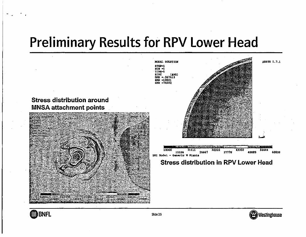
Preliminary Results for RPV Lower HeadNODAL SOLUTION
STEP-ISUB -1TINE-1SINT (AW)DMX -. 067615SMN -10801SMX -74682
4NSYS 5.7.1
Stress distribution aroundMNSA attachment points
10000 21111 32222 43333 5444415556 26667 37778 40889 60000
BMI Model - Generic W Plants
Stress distribution in RPV Lower Head
B NFL Slide 26~~~~~~~~~~~~~~~~~~~~~~~~~~~~~~~~~~~~~~~~~~~~~~~~~~~~~~
Q)BNFL Slide 26 OWestinghouse

Qualification Testing
* Functional testing previously completed for thepressurizer application
* These tests are applicable to the BMI application,because
- The Pressurizer heater sleeves envelope the BMI nozzlesizes
- Hillside effects are more severe in the pressurizer
- Temperatures are higher in the pressurizer
- Thermal transient rates are more severe in the pressurizerOOOOOA.2
BNFL Westinghouse

Qualification Testing (cont.)* Leak testing
Hydrostatic Test
>> Test in accordance with ASME Code demonstrates zero leakage
Thermal Cycle Test
> 3 Heat-up/Cool-down Cycles demonstrates zero leakage
Seismic Load Test
>> Demonstrates zero leakage
>> Establishes rigidity
* Axial Compression Test on Belleville Washer Packs- Determines stiffness values for FEA model
OOOOOA.3
A2" BNFL Westinghouse

Seismic Qualification Setup
* MNSA-2 is
* Frequency
"Rigid"
is > 50 Hz
* Sine sweep testingperformed pressurized to3000 psi
(DBNFL Slide 29 BWestinghouse

Corrosion Evaluation of Nozzle Bore* Primary coolant will leak through cracks and fill annulus
between nozzle and vessel-Unclad low alloy steel exposed to primary coolant-Some general corrosion of the steel will occur during
operation, outages, startups-Calculate an overall corrosion rate-Estimate total corrosion (increase in hole diameter) to
end-of-life-Calculate maximum increase in hole diameter beforeCode rules exceeded
-Compare total lifetime corrosion with the maximumincrease in hole size to demonstrate acceptability to EOL
GBNFL Slide 30 (SWestinouse

Flaw Evaluation--------- -
-
* Flaw evaluation performed inaccordance with ASME CodeSection Xl
* Free field stresses in RPVLHdetermined with 3-D FEA model-Maximum combined pressure +
thermal stress* Assumed flaw
-Through cladding, butter and J-weld
* Stress intensity factorsdetermined using Raju-Newmancorrelations
�mI
Bore Hole.....
aBore Hole Wall
-I-.-.-.-.- ........................flt {
Clad
Base -
Mea
a~~~~---
BNFL Slide 31 �WesUnghouse
(DBNFL Slide 31 OWestinghouse

Preliminary Risk Analysis
BNFL Slide 32 O Westinghouse
(DBNFL Slide 32 OWestinghouse

Preliminary Risk Analysis Results
* A risk model was prepared in terms of an event treewhich is quantified for a spectrum of cases to simulate theuncertainty in the j-weld flaw probabilities.
* All reasonably realistic cases meet the risk acceptancecriteria of CDF < 1.OE-06/year comfortably, for one ormore MNSAs installed for both Westinghouse and B&Wdesigned plants.
OOOOOA.13
11BNFL G Westinghouse

Preliminary Risk Analysis Results
* For Westinghouse designed plants, the best estimatecase, results in a CDF of 1 .56E-1 0/year. The upperbound estimate results in a CDF of 1.56E-09/year.
* For B&W designed plants, the calculated CDF values are2.14E-1 0/year (best estimate), and 2.14E-09/year (upperbound).
* With these small values of CDF, the LERF criteria are alsomet.
* The risk of vessel failure due to MNSA installation isessentially unchanged.
OOOOOA.14
BNFL * Westinghouse

Risk Analysis Results
* A risk model was prepared in terms of an event treewhich is quantified for a spectrum of cases to simulate theuncertainty in the j-weld flaw probabilities.
* All reasonably realistic cases meet the risk acceptancecriteria of CDF < 1.OE-06/year comfortably, for one ormore MNSAs installed for both Westinghouse and B&Wdesigned plants
OOOOOAA4
X RBNFL S ga Westinghouse

Risk Analysis Results
* For Westinghouse designed plants, the best estimatecase, results in a CDF of 1.56E-10/year. The upperbound estimate results in a CDF of 1.56E-09/year.
* For B&W designed plants, the calculated CDF values are2.14E-1 0/year (best estimate), and 2.14E-09/year (upperbound).
* With these small values of CDF, the LERF criteria are alsomet
* The risk of vessel failure due to MNSA installation isessentially unchanged
OOOOOA.5
BNFL Westinghouse

MNSA-2 Relief Request Overview
BNFL Slide 36 O Westinghouse
Idol&
Q)BNFL Slide 36 (SWestinghouse

MNSA=2 Relief RequestThis section discusses the Relief Request for theMINSA-2.
* In the event of a leaking BMI, it is recognized thatadditional information will be required for return topower such as:
- NDE results of all penetrations
- Root Cause analysis
- Failure Modes & Effects Analysis
- Future plans for inspection & monitoringOOOOOA.1 1
BNFL Westinghouse

MNSA-2 Relief Request
*System- Reactor Coolant System (RCS)
*Components- Will identify specific nozzle locations
*ASME Code Applicability-Will identify year/addenda for each site-Section Xl applicability
-Section III applicability
OBNFL Slide 38 O Westinghouse

l.
MNSA-2 Relief Request
Code Requirements- Rules for replacing ASME Sect. Ill Class 1 welded nozzle integrity
with mechanical clamps are not clearly defined in ASME Section III
- Code interpretation allows mechanical connections if designed toASME Section III
* MNSA-2 a proposed alternative to weldedconnection
Basis for Relief- Cite regulatory provisions for relief [10 CFR 50.55(a)(3)(i)]
- The MNSA-2 will provide an acceptable level of quality & safetyOOOOOA.6
BNFL Westinghouse
MNSA-2 Relief Request
* Basis for proposed alternative-Current design of nozzle-MNSA-2 Application, Description, & Design
- Design-Materials of construction-Structural analysis of MNSA-Structural analysis of vessel with MNSA-Flaw evaluation-Corrosion evaluation-Qualification Testing
OBNFL Slide 40 Westinghouse

MNSA-2 Relief Request
* Pre-service Testing & Inspection in accordance with ASMESection Xl
-VT-1 on bolting in accordance with IWA-4820-Pressure test & VT-2 inspection performed as part of
plant restart at normal operating pressure inaccordance with IWA-471 0(c) & Code Case N-416
* In-service Testing & Inspection in accordance with ASMESection Xi-VT-2 inspection performed prior to plant start-up following
each refueling outage-VT-1 in-service inspection for category B-G-2
(DBNFL Slide41 OWestinghouse

ao 1,
Wrap-Up
* This presentation has covered-MNSA-2 design details-Operating experience-Status and discussion of structural analysis
being performed-Corroborating test information-Preliminary risk analysis results-Format of relief request
* Are there any other issues associated with the useof MNSA for the BMI application?
GBNFL Slide 42 (sWestinghouse

Back-Up Slides
BNFL Slide 43 Westinghouse~~~~~~~~~~~~~~~~~~~~~~~~~~~~~~~~~~~~~~~~~~~~~~~~~~~~~~~~~~~~~~~~~~~~~~~~
(BNFL Slide 43 sWestinghouse

MNSA-2
e Seismic Test MNSA-2
T4
Inboard/4Fla
Channel
Compres
BNFL SIide�
(DBNFL Slide 44

Compression Collar
* Split Compression Collar-Weep holes allows fluid tobe channeled away fromvessel in event of primaryseal leakage
GBNFL Slide45 BWestinghouse

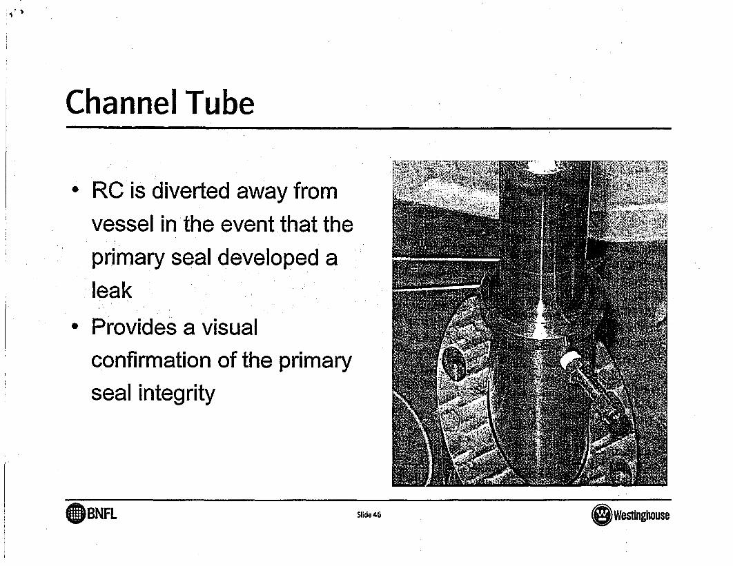
Channel TubeOp F.~~~~~~~~~~~~~~~~~~~~~~~~~~~~~~~~~~~~~~
* RC is diverted away fromvessel in the event that theprimary seal developed aleak
* Provides a visualconfirmation of the primaryseal integrity
G BNFL ~~~~~~~~~~Slide 46 (O)Westinghouse
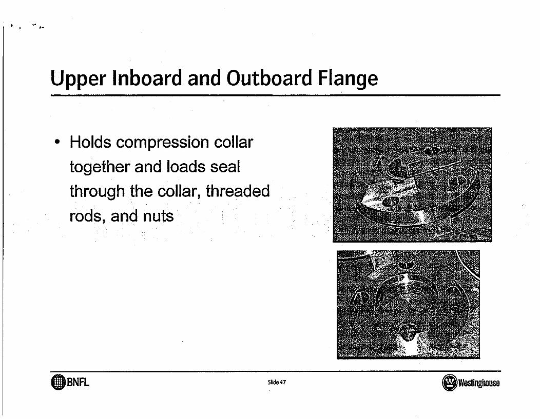
Upper Inboard and Outboard Flange
* Holds compression collartogether and loads sealthrough the collar, threadedrods, and nuts
BNFL Slide 47 Westinghouse
Aa&
AmBNFLw Slide 47 (Swestinghouse

* .
Inboard Upper Flange
* Inboard flangeassembled ontocompression collar
• Outboard flange fitsover the top of inboardflange forming acontinuous solid flange
( BNFL ~~~~~~~~~~Slide 48 (s)Westinghouse

Back-Up Slides
BNFL Slide 43 Westinghouse
Q)BNFL Slide 43 OWestinghouse

MNSA-2
* Seismic Test MNSA-2
T(
Inboard/4
Cha
Channel
Compres
BNFL Slide 44
(DBNFL Slide 44

Compression Collar
* Split Compression Collar-Weep holes allows fluid tobe channeled away fromvessel in event of primaryseal leakage
BNFL SIide45 Westinghouse
(DBNFL 9ide 45 OWestinghouse
Channel Tube
*RO is diverted away fromvessel in the event that theprimary seal developed aleak
*Provides a visualconfirmation of the primaryseal integrity
( BNFL ~~~~~~~~~~Slide 46 O Westinghouse

Upper Inboard and Outboard Flange
* Holds compression collartogether and loads sealthrough the collar, threadedrods, and nuts
BNFL Slide 47 0 West~~~~~~~~~~~~~~~~~~~~~~~~~~~~~~~~~~~~~~~~~~~~~~~~~~~~~~~~~~~~~~~~~~~~~~~~~~~~~~~~~~~~~~~~~~~~~~~~~~~~~~~~~~~~~~~~~~~~~~~~~~~~~~~~~~~nghouse~~~~~~~~~~~~~~~~~~~~~~~~~~~~~~~~~~~~~~~~~~~()BNFL Slide 47 (OWestinghouse

Inboard Upper Flange
* Inboard flangeassembled ontocompression collar
* Outboard flange fitsover the top of inboardflange forming gacontinuous solid flange
(DBNFL ~~~~~~~~~~~Slide 48 o Westinghouse