1 announcements l bring motors to lab this week. l bring eight 1n4001 diodes to lab per team. get...
Post on 22-Dec-2015
214 views
TRANSCRIPT
1
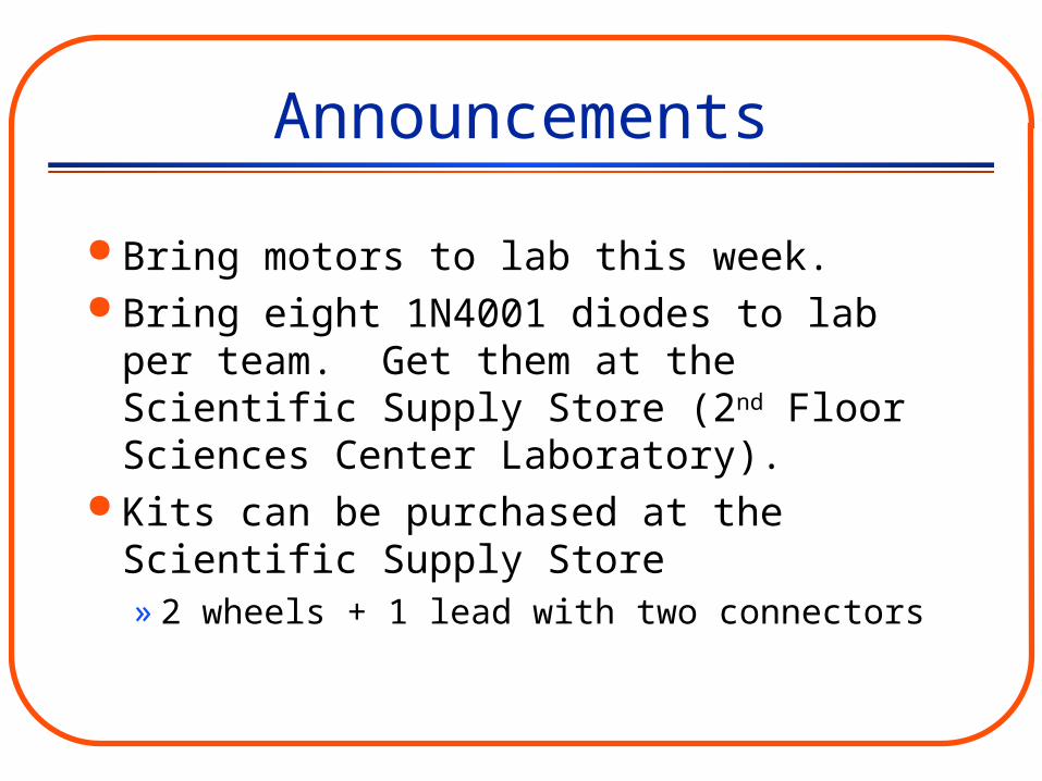
Announcements
Bring motors to lab this week. Bring eight 1N4001 diodes to lab per team.
Get them at the Scientific Supply Store (2nd Floor Sciences Center Laboratory).
Kits can be purchased at the Scientific Supply Store» 2 wheels + 1 lead with two connectors

2
Announcements Most of your work on the Lego car will be
done outside of lab and lecture.» Labs 3-7 and 9 are designed to provide the
technical knowledge and measurements required to design and build your car
» Lab 13 is an (optional) open lab when you can work on your car
– Week preceding the competition
– You should have your car designed and built by this lab
3
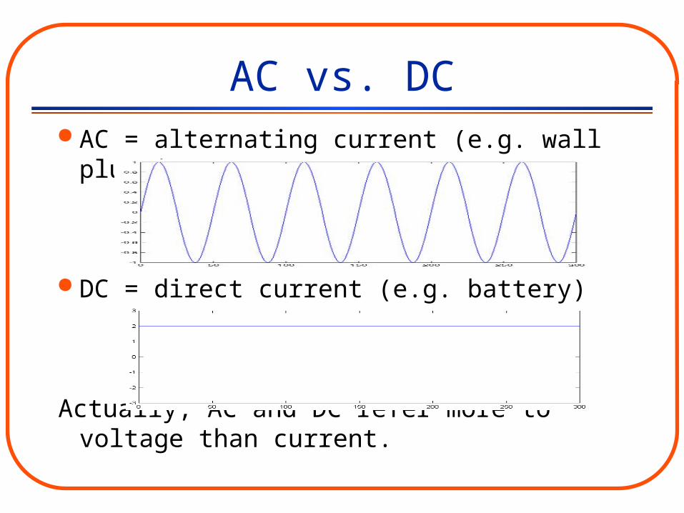
AC vs. DC AC = alternating current (e.g. wall plug-in)
DC = direct current (e.g. battery)
Actually, AC and DC refer more to voltage than current.

4
Period (T) – the time to complete one cycle of the waveform (Units: seconds)
Frequency (f=1/T) – the number of cycles per second (Units: hertz, Hz=1 cycle/s)
AC terminologyT = 50milliseconds = 0.05 seconds
f = 1/T = 1/0.05 = 20 HzT

5
Amplitude -- peak value of the signal (Units are V if a voltage source)» Measure from 0 to peak
AC terminology
Amplitude = 1V

6
RMS value -- “root-mean-square”, or square root of average squared value. Equal to amplitude/ for sine wave.
» Example: Sine wave with amplitude of 5V– RMS value = 5/1.4159 = 3.54V
AC terminology
2

7
AC to DC
Problem #1: Audio amplifier will not generate DC
waveform, since the ear cannot hear DC (constant) or low frequencies (< 20 Hz)

8
Amplifiers Amplifiers respond differently to different frequencies

9
Audio Amplifier Response
This plot shows the output of an audio amplifier to an input sine wave of constant amplitude but different input frequencies.
Frequency in Hertz
RM
S A
mpl
ifie
r R
espo
nse
in V
olts

10
AC to DC
Problem #2: Legos® motors are DC motors. They will
not turn with an AC power supply. (Or at least they will not turn constantly in the same direction!)
11
AC to DC
Another way to state the problem is that an AC signal has a zero average value.
To drive the motor consistently in one direction, we need an input signal with a non-zero average value.
12
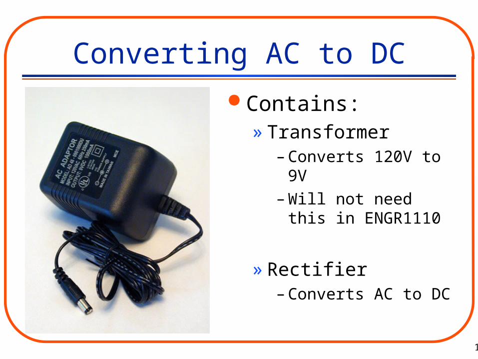
Converting AC to DC
Contains:» Transformer
– Converts 120V to 9V
– Will not need this in ENGR1110
» Rectifier– Converts AC to DC

13
Converting AC to DC
Two types of rectifiers
» Half-Wave
» Full-Wave or Bridge
14
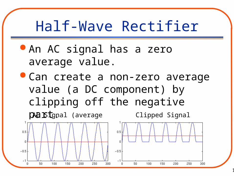
Half-Wave Rectifier An AC signal has a zero average value. Can create a non-zero average value (a DC
component) by clipping off the negative part.
AC Signal (average in red) Clipped Signal (average in red)
15
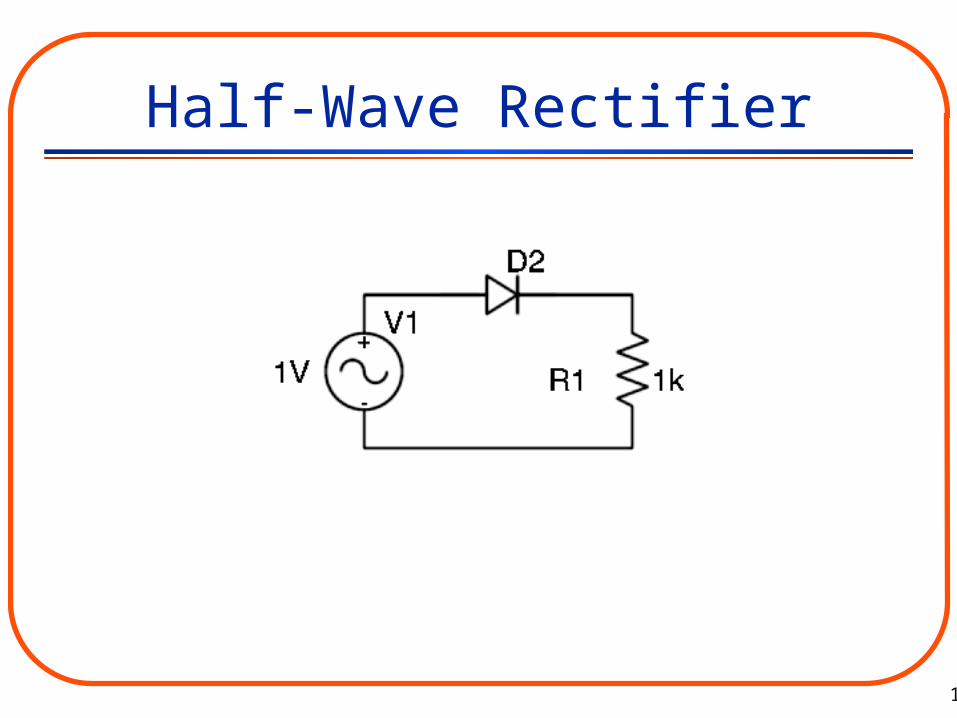
Half-Wave Rectifier
16
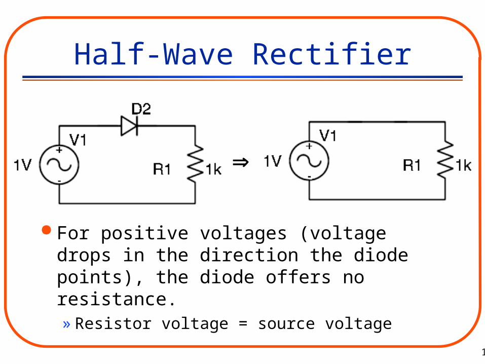
Half-Wave Rectifier
For positive voltages (voltage drops in the direction the diode points), the diode offers no resistance.» Resistor voltage = source voltage

17
Half-Wave Rectifier
For negative voltages (voltage rises in the direction the diode points), a diode offers infinite resistance. » Acts like an open circuit
– Current (I) = 0
» Resistor voltage = 0V Why?
V=IR and I=0

18
Half-Wave Rectifier
0 0.1 0.2 0.3 0.4 0.5 0.6 0.7 0.8 0.9 1-1
-0.8
-0.6
-0.4
-0.2
0
0.2
0.4
0.6
0.8
1
0 0.1 0.2 0.3 0.4 0.5 0.6 0.7 0.8 0.9 1-1
-0.8
-0.6
-0.4
-0.2
0
0.2
0.4
0.6
0.8
1
0 0.1 0.2 0.3 0.4 0.5 0.6 0.7 0.8 0.9 1-1
-0.8
-0.6
-0.4
-0.2
0
0.2
0.4
0.6
0.8
1
0 0.1 0.2 0.3 0.4 0.5 0.6 0.7 0.8 0.9 1-1
-0.8
-0.6
-0.4
-0.2
0
0.2
0.4
0.6
0.8
1
+
-
+
-
Source (input) voltage
Resistor (output)voltage

19
Half-Wave RectifierInput voltage Output voltage
+
-

20
Half-Wave Rectifier
The half-wave rectifier “wastes” part of the input signal, since the negative lobes of a sine wave are just clipped off.
It is possible to use both the positive and negative lobes with a full-wave bridge rectifier.

21
Bridge Rectifier The circuit below inverts the negative lobes
of a sine wave and preserves the positive lobes.

22
Bridge Rectifier
0 0.1 0.2 0.3 0.4 0.5 0.6 0.7 0.8 0.9 1-1
-0.8
-0.6
-0.4
-0.2
0
0.2
0.4
0.6
0.8
1
0 0.1 0.2 0.3 0.4 0.5 0.6 0.7 0.8 0.9 1-1
-0.8
-0.6
-0.4
-0.2
0
0.2
0.4
0.6
0.8
1
0 0.1 0.2 0.3 0.4 0.5 0.6 0.7 0.8 0.9 1-1
-0.8
-0.6
-0.4
-0.2
0
0.2
0.4
0.6
0.8
1
0 0.1 0.2 0.3 0.4 0.5 0.6 0.7 0.8 0.9 1-1
-0.8
-0.6
-0.4
-0.2
0
0.2
0.4
0.6
0.8
1
-
+
-
+

23
Bridge Rectifier The result of the bridge rectifier is shown in
the plot on the right.
AC Signal (average in red) Clipped Signal (average in red)

24
Bridge Rectifier Notice that the average value is higher than
for a half-wave rectifier but at the cost of three extra diodes.
Half-wave rectifier Bridge rectifier

25
Capacitor Filter
In the circuit below, the capacitor begins to “fill up” when the source voltage is positive. When the source is negative, the capacitor begins to discharge and acts like a temporary battery to keep up the voltage across R.

26
Capacitor Filter
A typical plot of output voltage (across R) for a capacitor filter is shown below:
27
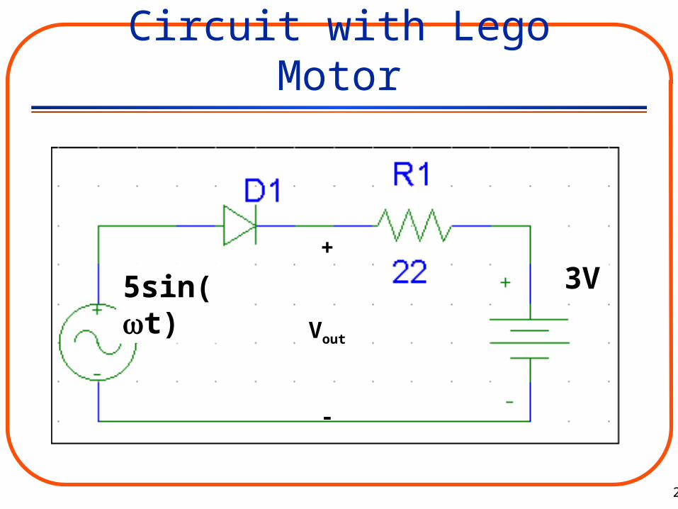
Circuit with Lego Motor
+
Vout
-
3V5sin(t)
28
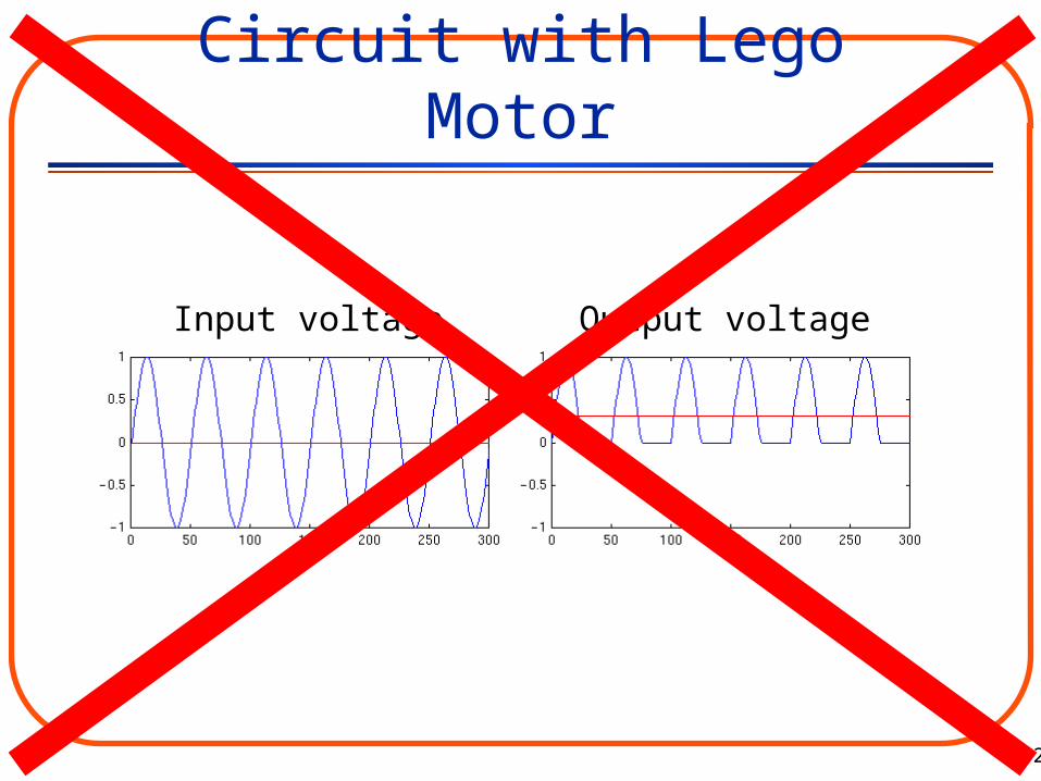
Circuit with Lego Motor
Input voltage Output voltage

29
Circuit with Lego Motor
+
Vout
-
3V5sin(t)
30
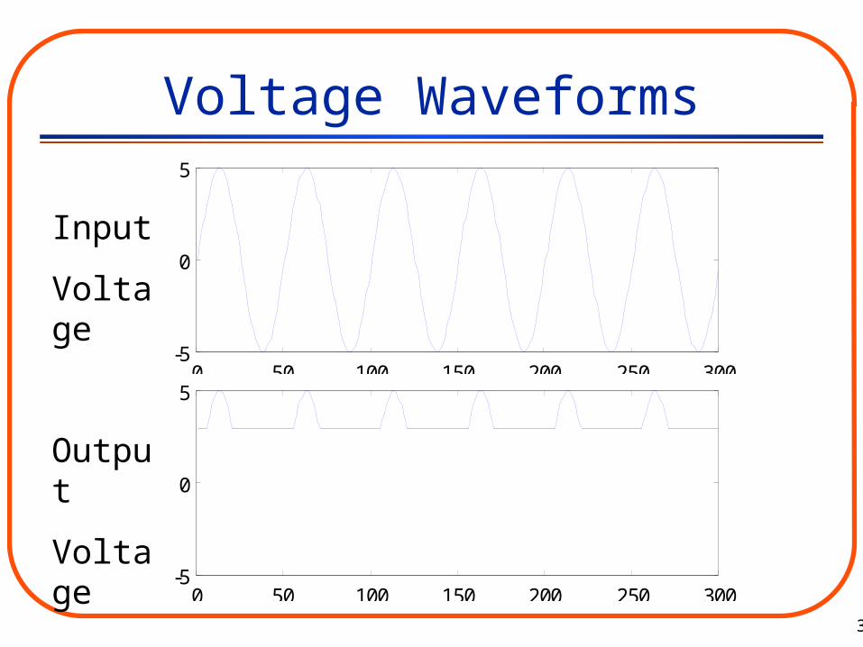
Voltage Waveforms
0 50 100 150 200 250 300-5
0
5
0 50 100 150 200 250 300-5
0
5
Input
Voltage
Output
Voltage

31
1. Let R1=10 ohms, and R2=20 ohms. Find the voltage V2 if V1=6V.
2. Electrical voltage is analogous to which quantity related to water flowing through a pipe?
a) pressure b) flow rate c) volume
3. Electrical current is analogous to which quantity related to water flowing through a pipe?
a) pressure b) flow rate c) volume
QuizPut name, lab day and time, and section number on quiz!!