1 ee 543 theory and principles of remote sensing antenna systems
TRANSCRIPT
1
EE 543Theory and Principles of
Remote Sensing
Antenna Systems

O. Kilic EE 543
2
Outline• Introduction• Overview of antenna terminology and antenna parameters
– Radiation Pattern• Isotropic, omni-directional, directional• Principal planes• HPBW• Sidelobes
– Power Density– Radiation Intensity– Directivity– Beam Solid Angle– Gain and Efficiency– Polarization and Polarization Loss Factor (PLF)– Bandwidth
• Antennas as Receivers• Circuit representation of an antenna• Reciprocity• Friis transmission equation
O. Kilic EE 543
3
Outline
• Radiation from currents and apertures– Sources of radiation– Current (wire) antennas
• Vector and scalar potentail• Short (Hertzian) dipole• Linear antennas
– Aperture fields (e.g. horn antennas)• Kirchoff’s scalar diffraction theory• Vector diffraction theory
– Array Antennas• Array Factor• Main beam scanning• Endfire antennas• Pattern Multiplication• Directivity calculations
O. Kilic EE 543
4
Summary
• So far we have discussed how waves interact with their surrounding in various ways:– Wave equation– Lossy medium– Plane waves, propagation– Reflection and transmission
• In this topic we discuss how waves are generated and received by antennas.
O. Kilic EE 543
5
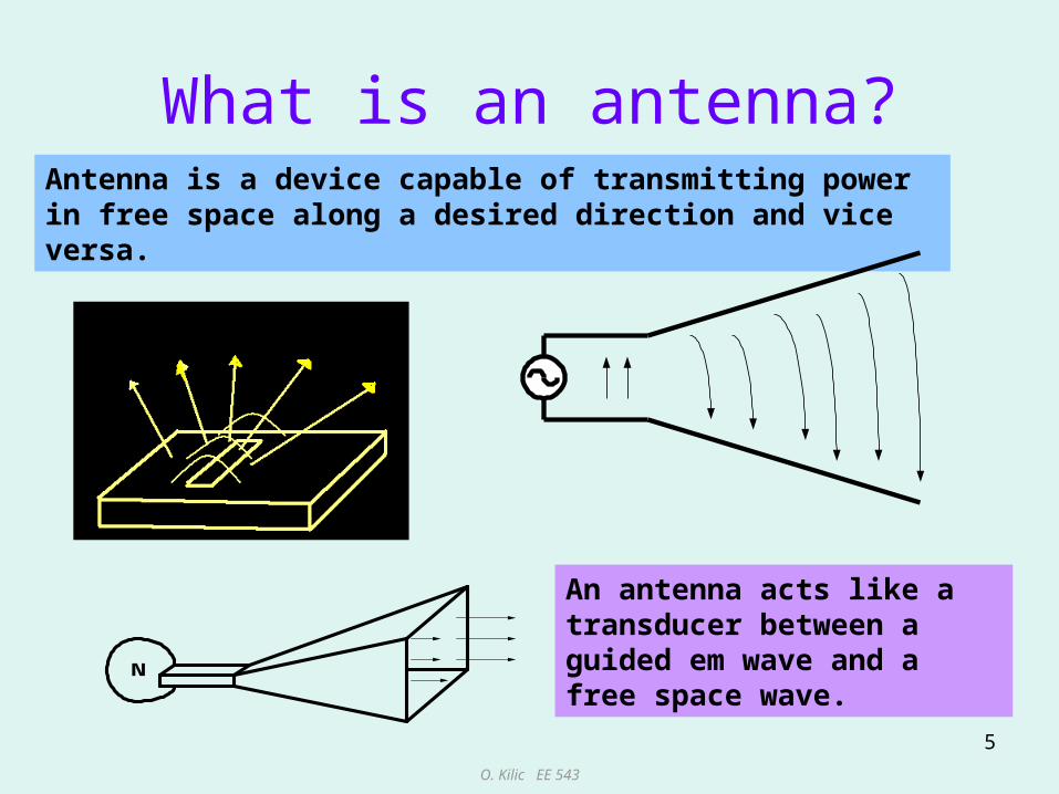
What is an antenna?Antenna is a device capable of transmitting power in free space along a desired direction and vice versa.
N
An antenna acts like a transducer between a guided em wave and a free space wave.
O. Kilic EE 543
6
What is an antenna
• Any conductor or dielectric could serve this function but an antenna is designed to radiate (or receive) em energy with directional and polarization properties suitable for the intended application.
• An antenna designer is concerned with making this transition as efficient as possible, ensuring as much power as possible is radiated in the desired direction.
O. Kilic EE 543
7
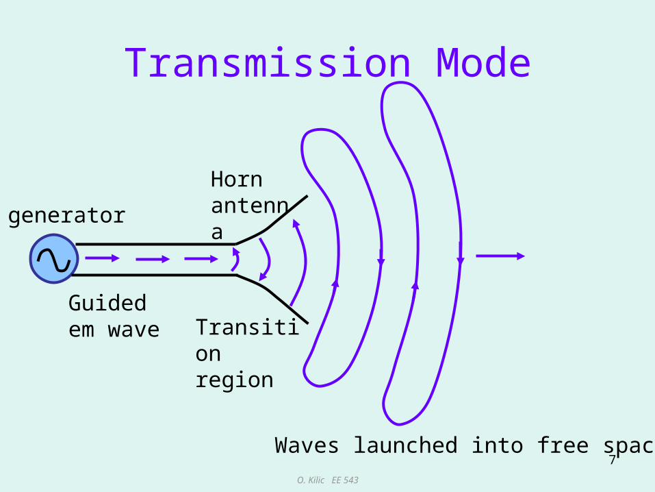
Transmission Mode
generator
Guided em wave Transition
region
Waves launched into free space
Horn antenna

O. Kilic EE 543
8
Reception Mode
detector
Guided em wave Transition
regionIncident wave
Receiver
O. Kilic EE 543
9
Antenna Types
• Antennas come in various shapes and sizes.
• Key parameters of an antenna are its size, shape and the material it is made of.
• The dimensions of an antenna is typically in wavelength,, of the wave it launches.

O. Kilic EE 543
10
Some examples
Thin dipole Biconal dipole loop
Parabolic reflector microstrip
O. Kilic EE 543
11
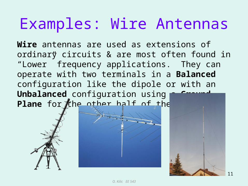
Examples: Wire AntennasWire antennas are used as extensions of ordinary circuits & are most often found in “Lower” frequency applications. They can operate with two terminals in a Balanced configuration like the dipole or with an Unbalanced configuration using a Ground Plane for the other half of the structure.

O. Kilic EE 543
12
Examples: Aperture AntennasAperture antennas radiate from an opening or from a surface rather than a line and are found at Higher frequencies where wavelengths are Shorter. Aperture antennas often have handfuls of sq. wavelengths of area & are very seldom fractions of a wavelength.

O. Kilic EE 543
13
Examples: Reflector AntennasReflector antennas collect or transmit (focus) energy by using a large (many wavelength) dish (or parabolic mirror). These are very high gain (directional) antennas used to communicate with or detect objects in space.

O. Kilic EE 543
14
How do these structures launch em energy?
• EM energy can be radiated by two types of sources:– Currents: (e.g. dipole, loop antennas. Time varying
currents flowing in the conducting wires radiate em energy.)
– Aperture fields: (e.g. horn antenna. E and H fields across the aperture serve as the source of the radiated fields.)
• Ultimately ALL radiation is due to time varying currents. (E and H fields across the horn aperture is created by the time varying currents on the walls of the horn.)
O. Kilic EE 543
15
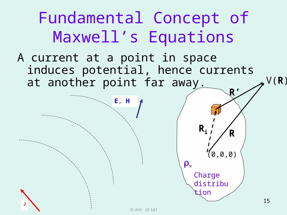
Fundamental Concept of Maxwell’s Equations
A current at a point in space induces potential, hence currents at another point far away.
J
E, H
v
Charge distribution
RRi
R’
(0,0,0)
V(R)

O. Kilic EE 543
16
Overview of Antenna Parameters
– Radiation Pattern– Radiation Power Density– Radiation Intensity– Directivity– Gain and Efficiency– HPBW– Polarization and Polarization Loss Factor (PLF)– Bandwidth– Beam Solid Angle

O. Kilic EE 543
17
Radiation Pattern (Antenna Pattern)
• An antenna pattern describes the directional properties of an antenna at a far away distance from it.
• In general the antenna pattern is a plot that displays the strength of the radiated field or power density as a function of direction; i.e. , angles.

O. Kilic EE 543
18
Coordinate System

O. Kilic EE 543
19
Solid Angle
lengtharcrad0.1
r
sr0.1
2rareasurface
2total circumference radians
224 rrSareasurfacetotal o
24oS
srr
ddrds )sin(2
ddr
dsd )sin(
2
Solid angle defines a subtended area over a spherical surface divided by R2.
Units: Steradians (Sr)
ddr
dsd )sin(
2
For unit angle:
For unit solid angle:

O. Kilic EE 543
20
Solid Angle
sindl r d
dl rd ddrds )sin(2

O. Kilic EE 543
21
Types of Radiation Patterns
IdealizedPoint Radiator Vertical Dipole Radar Dish
Isotropic Omni-directional Directional
O. Kilic EE 543
22
Isotropic Antenna
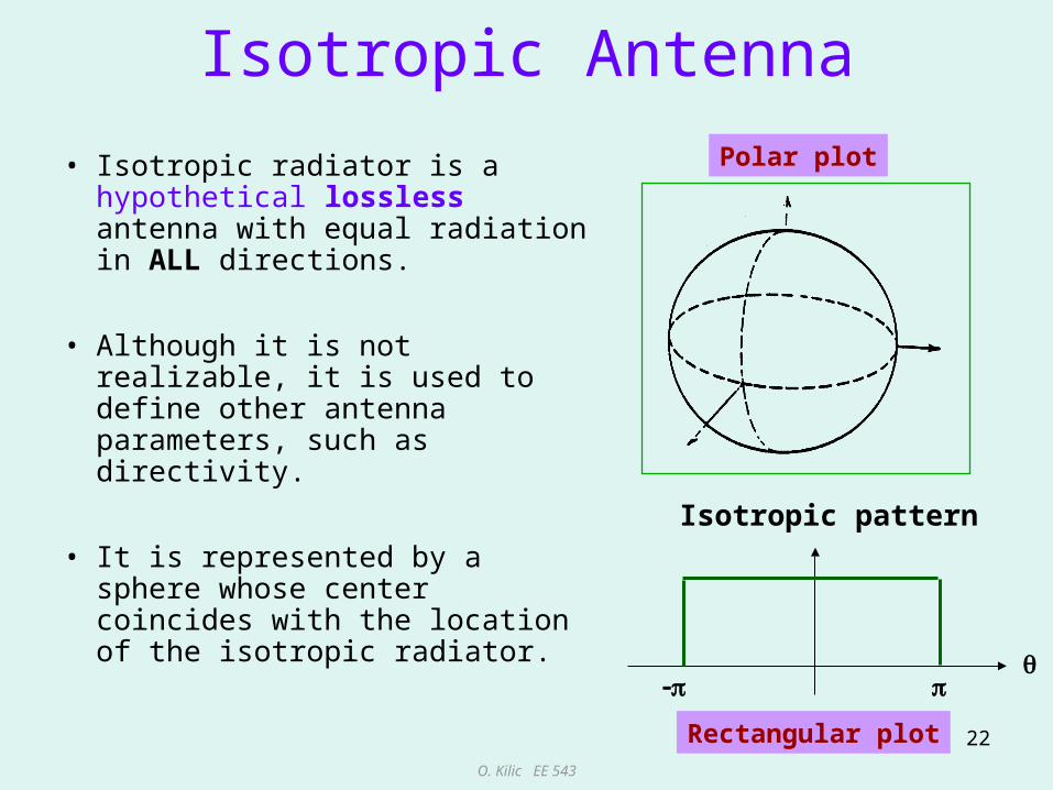
• Isotropic radiator is a hypothetical lossless antenna with equal radiation in ALL directions.
• Although it is not realizable, it is used to define other antenna parameters, such as directivity.
• It is represented by a sphere whose center coincides with the location of the isotropic radiator.
Isotropic pattern
Polar plot
Rectangular plot

O. Kilic EE 543
23
Directional Antenna
• Directional antennas radiate (or receive) em waves more efficiently in some directions than others.
• Usually, this term is applied to antennas whose directivity is much higher than that of a half-wavelength dipole.

O. Kilic EE 543
24
Omni-directional Antenna
Omni-directional antennas are special kind of directional antennas having non-directional properties in one plane (e.g. single wire antennas).

O. Kilic EE 543
25
Principal PlanesE and H planes
Antenna performance is often described in terms of its principal E and H plane patterns.
• E-plane – the plane containing the electric field vector and the direction of maximum radiation.
• H-plane – the plane containing the magnetic field vector and the direction of maximum radiation.
Note that it is usual practice to orient most antennas so that at least one of the principal plane patterns coincide with one of the geometrical planes

O. Kilic EE 543
26
Principal Planes
Another definition for principal planes is elevation () and azimuth () plane.

O. Kilic EE 543
27
Antenna Pattern Lobes
Full Null BeamwidthBetween
1st NULLS
Main lobe
Side lobes
Back lobes
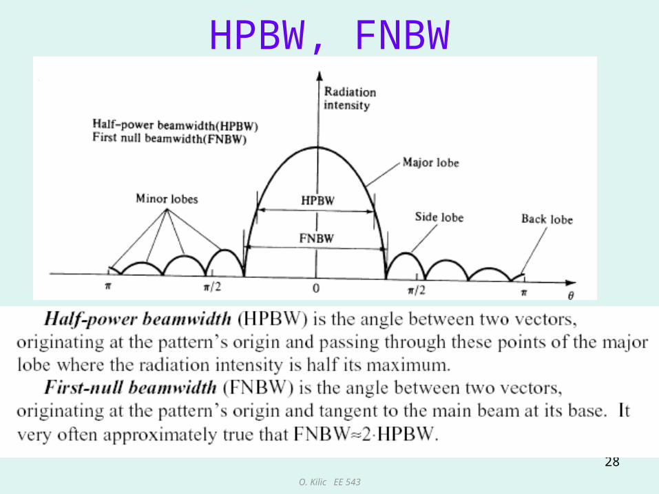
A pattern lobe is a portion of the radiation pattern bounded by regions of relatively weak radiation intensity.
nulls
Half power beamwidth
O. Kilic EE 543
28
HPBW, FNBW

O. Kilic EE 543
29
Field Regions• Close to the antenna, the field patterns change rapidly
with distance, and include both radiating energy and reactive energy energy oscillates toward and away from the antenna.
• In the near field region non-radiating energy dominates.• Further away, the reactive fields are negligible and only
the radiating energy is present.• Sufficiently far away; i.e. far field (Fraunhofer) region
field components are orthogonal. The angular distribution of fields and power density are independent of distance. Equipartition between electric and magnetic stored energy.
• In between is the transitional, radiating near field region also known as Fresnel region. The angular field distribution is dependent on the distance.
• Note that there is no abrupt change in the fields as the boundary between these regions is crossed.
O. Kilic EE 543
30
Field Regions
D
R1
R2
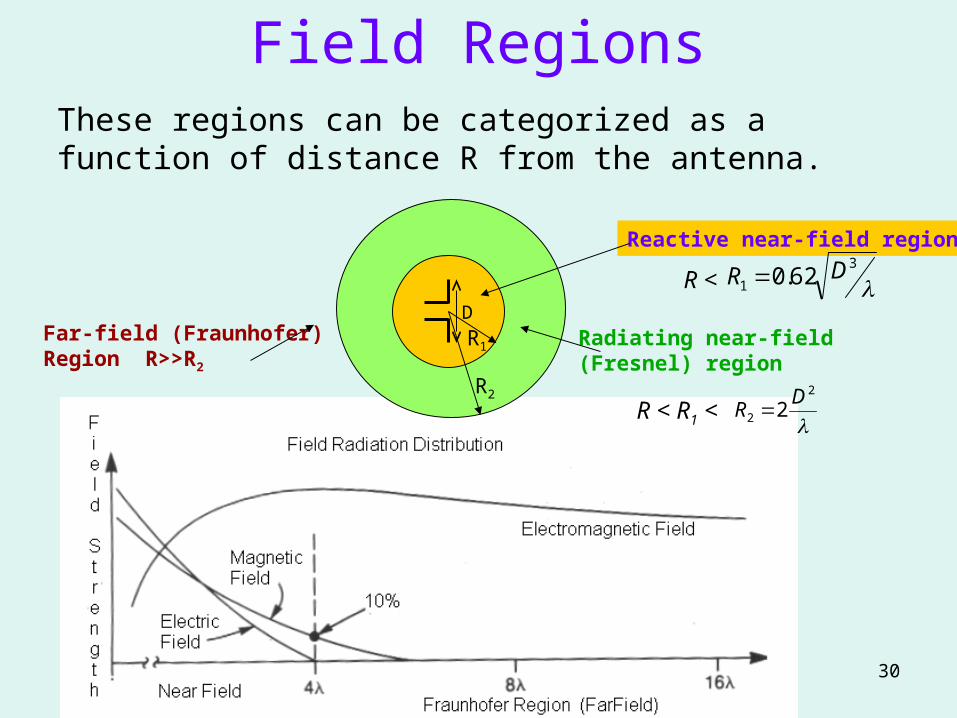
Reactive near-field region
3
1 62.0 DR
Radiating near-field (Fresnel) region
2
2 2D
R
Far-field (Fraunhofer) Region R>>R2
These regions can be categorized as a function of distance R from the antenna.
R <
R < R1 <
O. Kilic EE 543
31
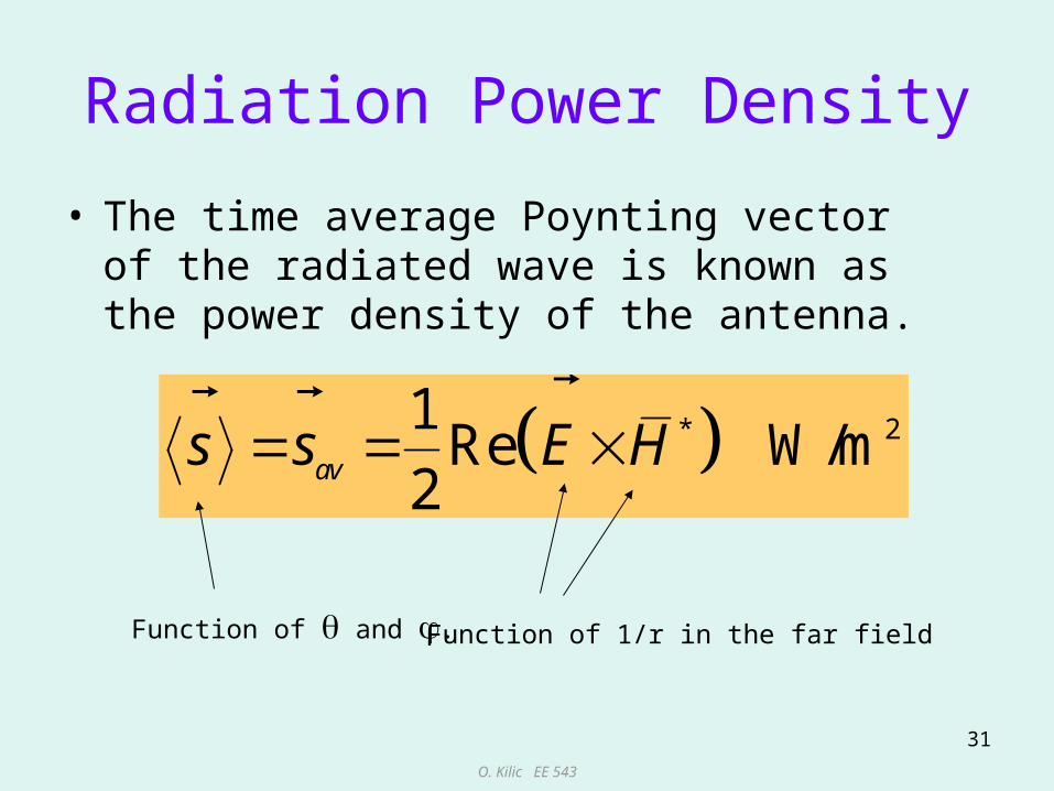
Radiation Power Density
• The time average Poynting vector of the radiated wave is known as the power density of the antenna.
* 21Re W/m
2
avs s E H
Function of and . Function of 1/r in the far field
O. Kilic EE 543
32
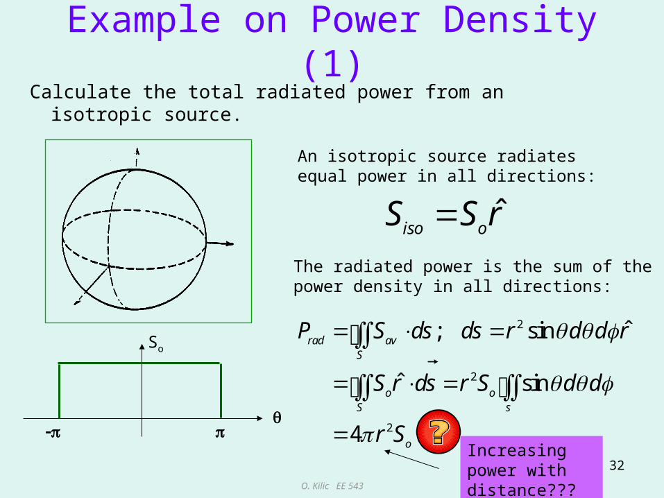
Example on Power Density (1)Calculate the total radiated power from an isotropic source.
ˆiso oS S r
An isotropic source radiates equal power in all directions:
The radiated power is the sum of the power density in all directions:
2
2
2
ˆ; sin
ˆ sin
4
rad avS
o oS s
o
P S ds ds r d d r
S r ds r S d d
r S
So
Increasing power with distance???

O. Kilic EE 543
33
Reiterate isotropic source
• An isotropic source radiates equal power in all directions at a given distance form the source.
• The distance is in the far field, and the power density is a function of 1/r2
• The power density of an isotropic source is
24tot
o
PS
r
O. Kilic EE 543
34
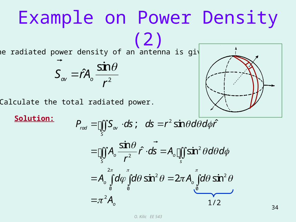
Example on Power Density (2)
2
sinˆ
av oS rAr
The radiated power density of an antenna is given by
Calculate the total radiated power.
Solution: 2
2
2
22 2
0 0 0
2
ˆ; sin
sinˆ sin
sin 2 sin
rad avS
o oS s
o o
o
P S ds ds r d d r
A r ds A d dr
A d d A d
A
1/2
O. Kilic EE 543
35
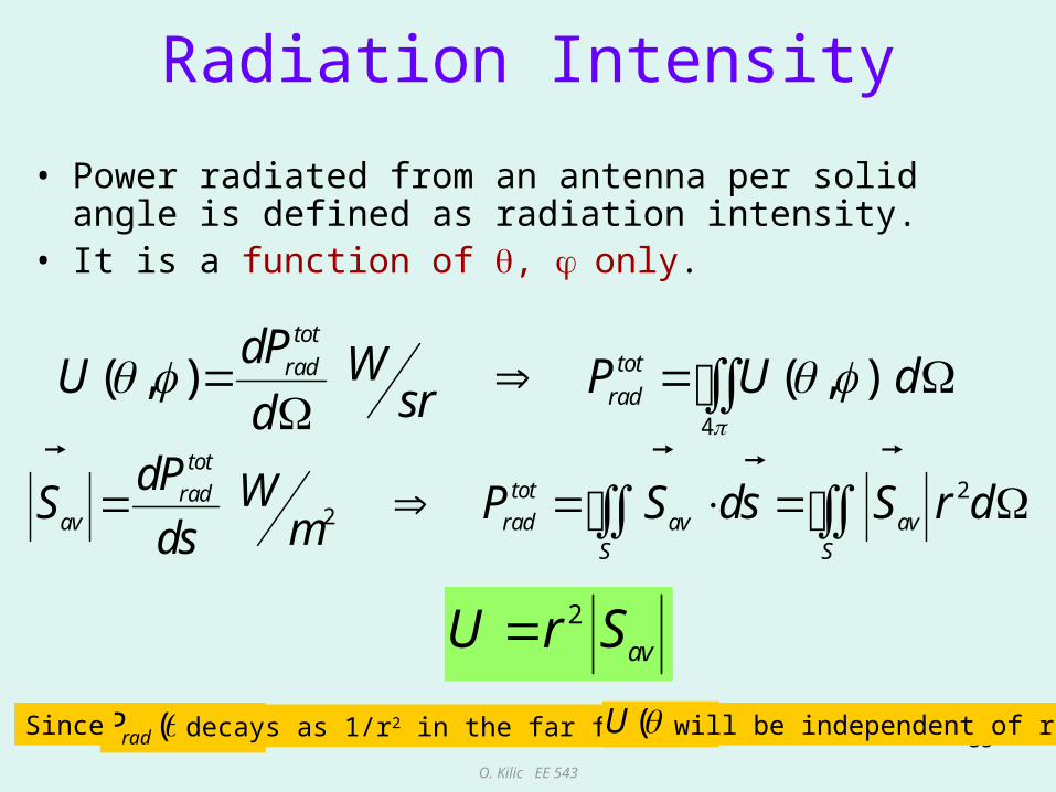
Radiation Intensity
• Power radiated from an antenna per solid angle is defined as radiation intensity.
• It is a function of , only.
4
( , ) ( , )tot
totradrad
dP WU P U dsrd
22
tottotrad
av rad av avS S
dP WS P S ds S r dmds
2
avU r S
),,( rPrad decays as 1/r2 in the far fieldSince ),( U will be independent of r
O. Kilic EE 543
36
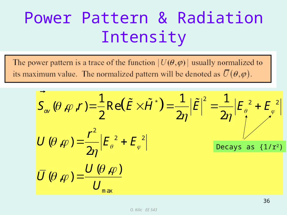
Power Pattern & Radiation Intensity
2* 2 2
22 2
max
1 1 1( , , ) Re
2 2 2
( , )2
( , )( , )
avS r E H E E E
rU E E
UU
U
Decays as {1/r2)
O. Kilic EE 543
37
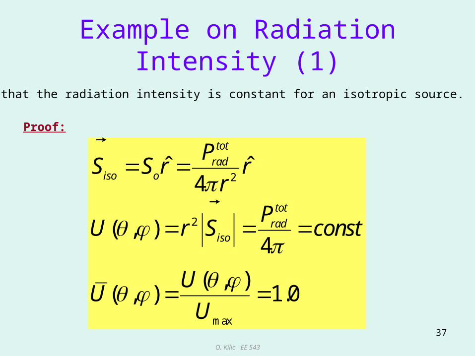
Example on Radiation Intensity (1)
2
2
max
ˆ ˆ4
( , )4
( , )( , ) 1.0
tot
radiso o
tot
radiso
PS S r r
rP
U r S const
UU
U
Show that the radiation intensity is constant for an isotropic source.
Proof:

O. Kilic EE 543
38
Example on Radiation Intensity (2)
2 2
2
2 2
ˆ
4
4 4
iso o
iso o o
o oo
S S r
P r S A
A AS
r r
2
rad oP A
For an antenna with average power density given by
calculate the power density of an equivalent isotropic radiator, which radiates the same amount of power.
Solution:
From previous example, the total radiated power for this antenna is given as
For an isotropic source to radiate the same power as this antenna:
So
Sav
2
sinˆ
av oS rAr
O. Kilic EE 543
39
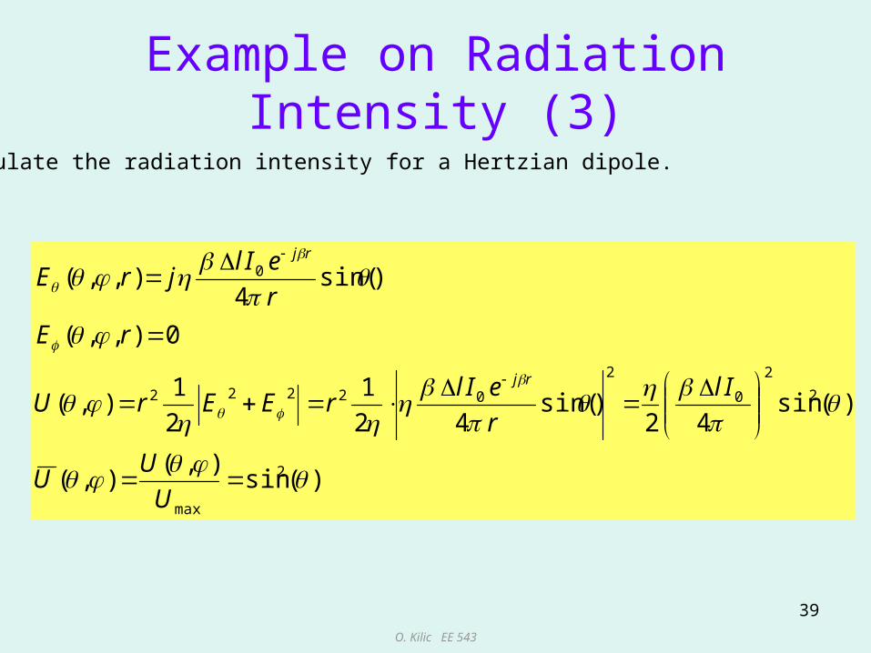
Example on Radiation Intensity (3)
)(sin),(
),(
)(sin42
)sin(42
1
2
1),(
0),,(
)sin(4
),,(
2
max
2
2
0
2
02222
0
U
UU
Il
r
eIlrEErU
rE
r
eIljrE
rj
rj
Calculate the radiation intensity for a Hertzian dipole.

O. Kilic EE 543
40
Beam Solid Angle
• The solid angle, A, required to radiate all the power of the antenna if the radiation intensity U were uniform and equal to its maximum value within the beam and zero elsewhere.
A
A Umax. A = Ptot

O. Kilic EE 543
41
Beam Solid Angle
Thus the total radiated power is given by Prad = Umax A
max
max max
2
0 0
( , )
( , )( , )
( , ) ( , )sin
rad A
A
A n n
P U d U
U dU
dU U
U d d d U
Normalized radiation intensity

O. Kilic EE 543
42
Directivity
Directivity is the ratio of the radiation intensity of an antenna in a given direction to the radiation intensity of an equivalent isotropic antenna.
maxmax
( , ) ( , ) ( , )( , ) 4
4
4 1 ( )
tot totrado rad
tot
rad
U U UD
PU P
UD directivity
P
O. Kilic EE 543
43
Directivity
• Directivity is a measure of how well antennas direct (focus) energy in one direction.
• For an isotropic source, the directivity is 1; i.e. exhibits no preference for a particular direction.
• Directivity is typically expressed in dB.• If a direction is not specified, typically the
maximum value is implied.

O. Kilic EE 543
44
Directivity Example (1)
0.1
0.1),(
4),(
4),(
o
totrad
totrad
o
D
P
UD
PUU
Show that the directivity of an isotropic source is 1.
O. Kilic EE 543
45
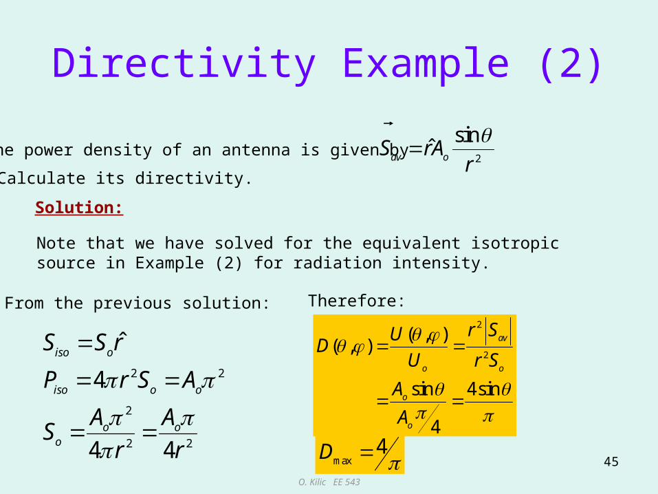
Directivity Example (2)
2
sinˆ
av oS rAr
2 2
2
2 2
ˆ
4
4 4
iso o
iso o o
o oo
S S r
P r S A
A AS
r r
2
2
( , )( , )
sin 4sin
4
av
o o
o
o
r SUD
U r S
A
A
The power density of an antenna is given by
Calculate its directivity.
Solution:
Note that we have solved for the equivalent isotropic source in Example (2) for radiation intensity.
max4D
Therefore:From the previous solution:
O. Kilic EE 543
46
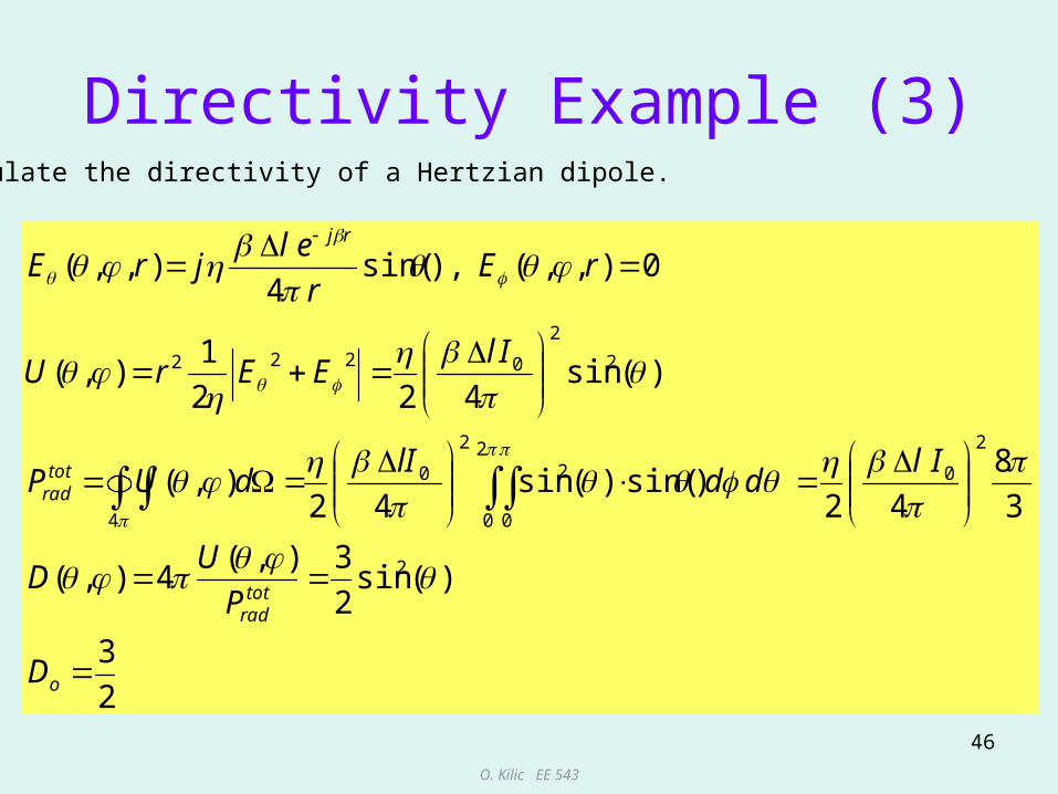
Directivity Example (3)
2
3
)(sin2
3),(4),(
3
8
42)sin()(sin
42),(
)(sin422
1),(
0),,(),sin(4
),,(
2
2
02
0 0
2
2
0
4
2
2
0222
o
totrad
totrad
rj
D
P
UD
Ildd
lIdUP
IlEErU
rEr
eljrE
Calculate the directivity of a Hertzian dipole.
O. Kilic EE 543
47
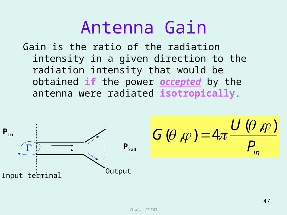
Antenna GainGain is the ratio of the radiation intensity in a
given direction to the radiation intensity that would be obtained if the power accepted by the antenna were radiated isotropically.
( , )( , ) 4
in
UG
P
Pin
Prad
Input terminalOutput
O. Kilic EE 543
48
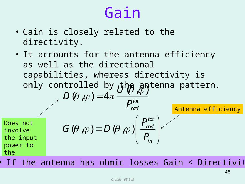
Gain• Gain is closely related to the directivity. • It accounts for the antenna efficiency as well
as the directional capabilities, whereas directivity is only controlled by the antenna pattern.
( , )( , ) 4
( , ) ( , )
tot
rad
tot
rad
in
UD
P
PG D
P
Antenna efficiency
Does not involve the input power to the antenna
If the antenna has ohmic losses Gain < Directivity.
O. Kilic EE 543
49
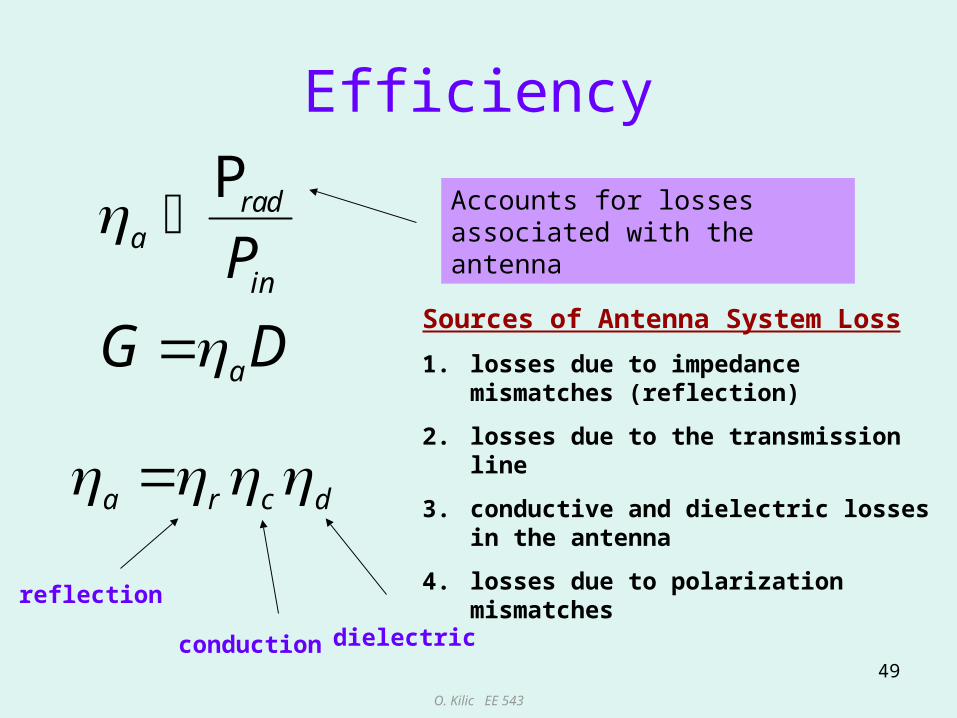
Efficiency
Prada
in
a
P
G D
Accounts for losses associated with the antenna
Sources of Antenna System Loss
1. losses due to impedance mismatches (reflection)
2. losses due to the transmission line
3. conductive and dielectric losses in the antenna
4. losses due to polarization mismatches
a r c d
reflection
conduction dielectric

O. Kilic EE 543
50
Overall Antenna Efficiency
The overall antenna efficiency is a coefficient that accounts for all the differentlosses present in an antenna system.
polarization mismatches
reflection efficiency (impedance mismatch)
conduction losses
dielectric losses
conductor & dielectriclosses
a
p r c d p r cd
p
r
c
d
cd
O. Kilic EE 543
51
Antenna Circuit Model
• The Tx antenna is a region of transition from a guided wave on a transmission line to a free space wave.
• The Rx antenna is a region of transition from a space wave to a guided wave on a transmission line.
• Thus, the antenna is a transitional circuit which interfaces a circuit and space.
O. Kilic EE 543
52
Antenna as a Circuit
• The input impedance of an antenna is the impedance presented by the antenna at its terminals.
• The input impedance will be affected by other antennas or objects that are nearby.

O. Kilic EE 543
53
Antenna and How It Responds to the Environment
TX or RX Antenna
Rr
Rr
Region of space within the antenna response pattern
Virtual transmission line linking the antenna with space
The radiation resistance can be thought of as a “virtual” resistance that couples the transmission line terminals to distant regions of space via a virtual transmission line.

O. Kilic EE 543
54
Antenna Impedance• For the discussions that follow, we will assume
that the antenna is in an isolated environment.• The input impedance of the antenna is
composed of real and imaginary parts:
Zin = Rin +jXin
• The input resistance, Rin represents dissipation in the form of heating losses (Ohmic losses) or radiation.
• The input reactance, Xin represents power stored in the near field of the antenna.
O. Kilic EE 543
55
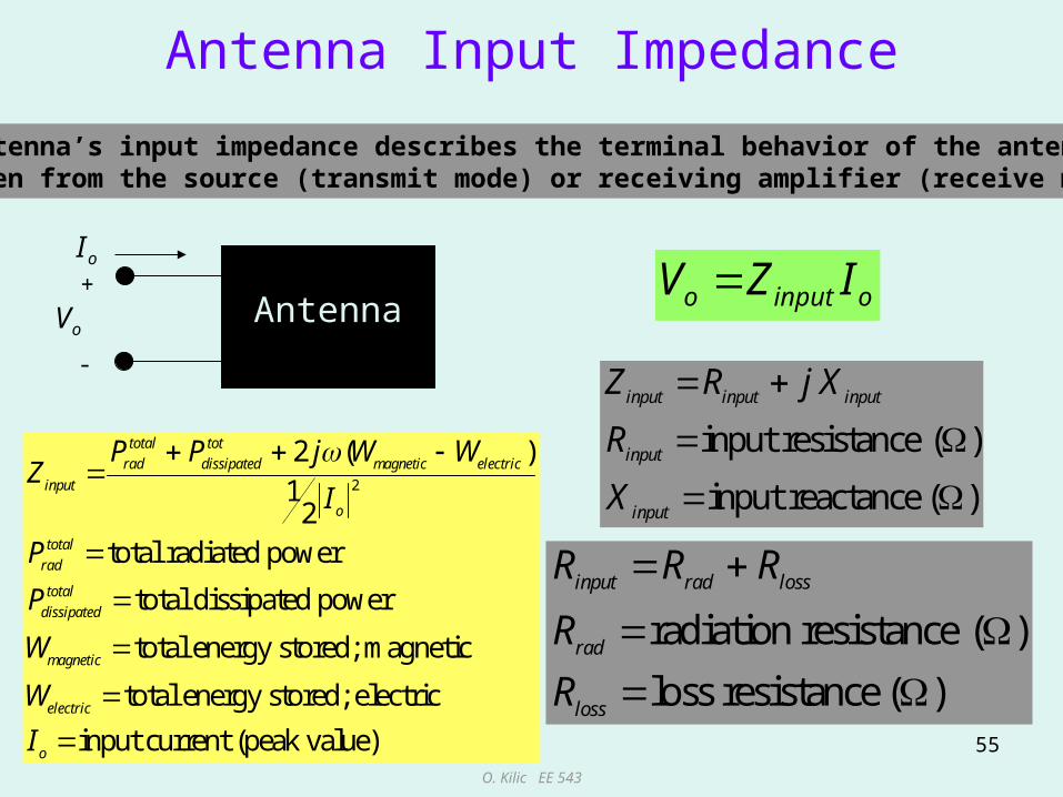
Antenna Input Impedance
An antenna’s input impedance describes the terminal behavior of the antennaas seen from the source (transmit mode) or receiving amplifier (receive mode).
input resistance ( )
input reactance ( )
input input input
input
input
Z R j X
R
X
Antenna oinputo IZV
radiation resistance ( )
loss resistance ( )
input rad loss
rad
loss
R R R
R
R
2
2 ( )1
2total radiated power
total dissipated power
total energy stored; magnetic
total energy stored;
total tot
rad dissipated magnetic electric
input
o
total
rad
total
dissipated
magnetic
electric
P P j W WZ
I
P
P
W
W
electric
input current (peak value)oI
oI+
-
oV
O. Kilic EE 543
56
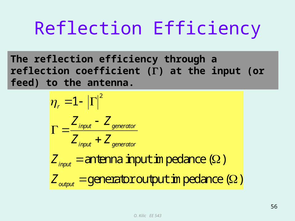
Reflection Efficiency
The reflection efficiency through a reflection coefficient () at the input (or feed) to the antenna.
21
antenna input impedance ( )
generator output impedance ( )
r
input generator
input generator
input
output
Z Z
Z Z
Z
Z

O. Kilic EE 543
57
Transmitting Antenna Circuit Model
Vg=generator voltage (peak)Rg=generator output resistanceXg=generator output reactanceRg=antenna conductor loss resistanceRr=antenna radiation loss resistanceXA=antenna input reactance
O. Kilic EE 543
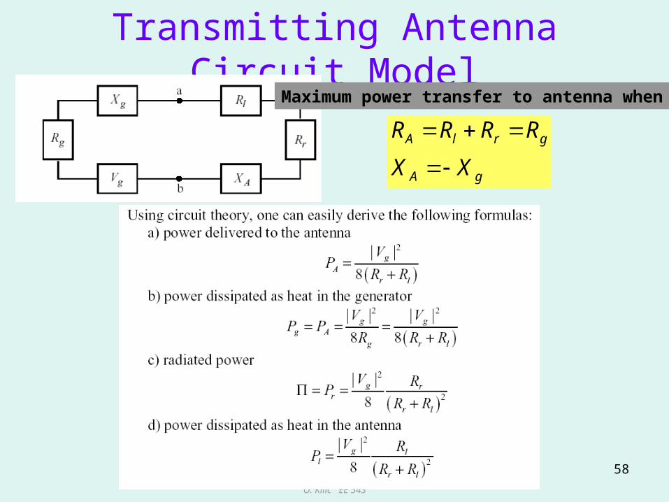
58
Transmitting Antenna Circuit ModelMaximum power transfer to antenna when
gA
grlA
XX
RRRR
O. Kilic EE 543
59
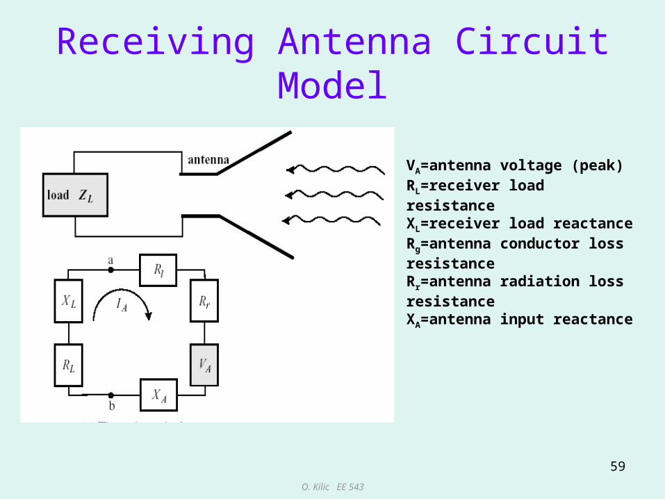
Receiving Antenna Circuit Model
VA=antenna voltage (peak)RL=receiver load resistanceXL=receiver load reactanceRg=antenna conductor loss resistanceRr=antenna radiation loss resistanceXA=antenna input reactance
O. Kilic EE 543
60
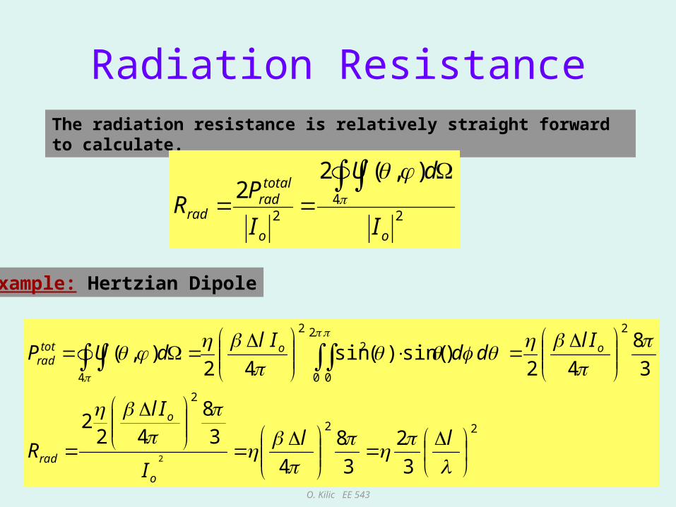
Radiation ResistanceThe radiation resistance is relatively straight forward to calculate.
24
2
),(22
oo
totalrad
radI
dU
I
PR
Example: Hertzian Dipole
22
2
22
0 0
2
2
4
3
2
3
8
4
38
422
3
8
42)sin()(sin
42),(
2
ll
I
Il
R
Ildd
IldUP
o
o
rad
oototrad
O. Kilic EE 543
61
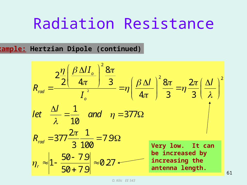
Radiation Resistance
Example: Hertzian Dipole (continued)
2
2
2 2
82
2 4 3 8 2
4 3 3
1377
102 1
377 7.93 100
50 7.91 0.27
50 7.9
o
rad
o
rad
r
l I
l lR
I
llet and
R
Very low. It can be increased by increasing the antenna length.

O. Kilic EE 543
62
Antenna Conduction and Dielectric Efficiency
radcd
cd rad
R
R R
Conduction and dielectric losses of an antenna are very difficult to separate and are usually lumped together to form the cd efficiency. Let Rcd represent the actual losses due to conduction and dielectric heating. Then the efficiency is given as
For wire antennas (without insulation) there is no dielectric losses only conductorlosses from the metal antenna. For those cases we can approximate Rcd by:
2 2 2o
cd s
l lR R
b b
where b is the radius of the wire, w is the angular frequency, s is the conductivityof the metal and l is the antenna length
O. Kilic EE 543
63
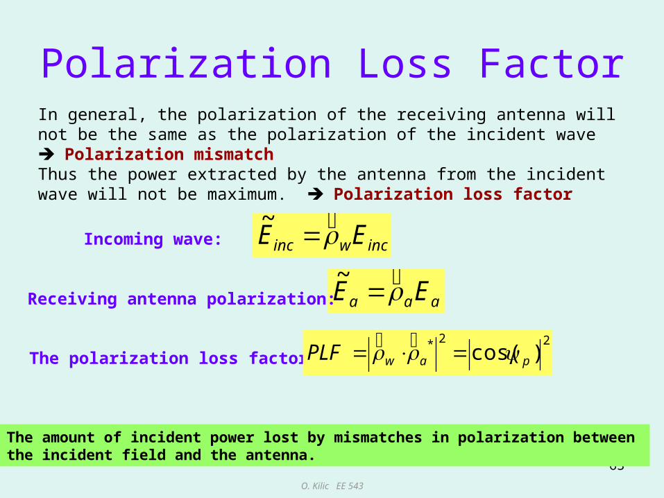
Polarization Loss Factor
incwinc EE ~
In general, the polarization of the receiving antenna will not be the same as the polarization of the incident wave Polarization mismatch Thus the power extracted by the antenna from the incident wave will not be maximum. Polarization loss factor
aaa EE ~
The polarization loss factor:22* )cos( pawPLF
The amount of incident power lost by mismatches in polarization between the incident field and the antenna.
Incoming wave:
Receiving antenna polarization:

O. Kilic EE 543
64
Effective Aperture
plane waveincident
AphysicalPload
?
load physical incP A S
Question:
Answer: Usually NOT
loadload eff inc eff
inc
PP A S A
S
How much power can we pick up with a receive antenna???
O. Kilic EE 543
65
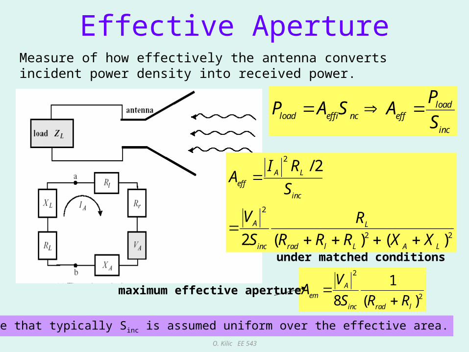
Effective Aperture
under matched conditions
loadload eff inc eff
inc
PP A S A
S
2
2
2 2
/ 2
2 ( ) ( )
A L
eff
inc
A L
inc rad l L A L
I RA
S
V R
S R R R X X
2
2
1
8 ( )A
em
inc rad l
VA
S R R
maximum effective aperture
Note that typically Sinc is assumed uniform over the effective area.
Measure of how effectively the antenna converts incident power density into received power.
O. Kilic EE 543
66
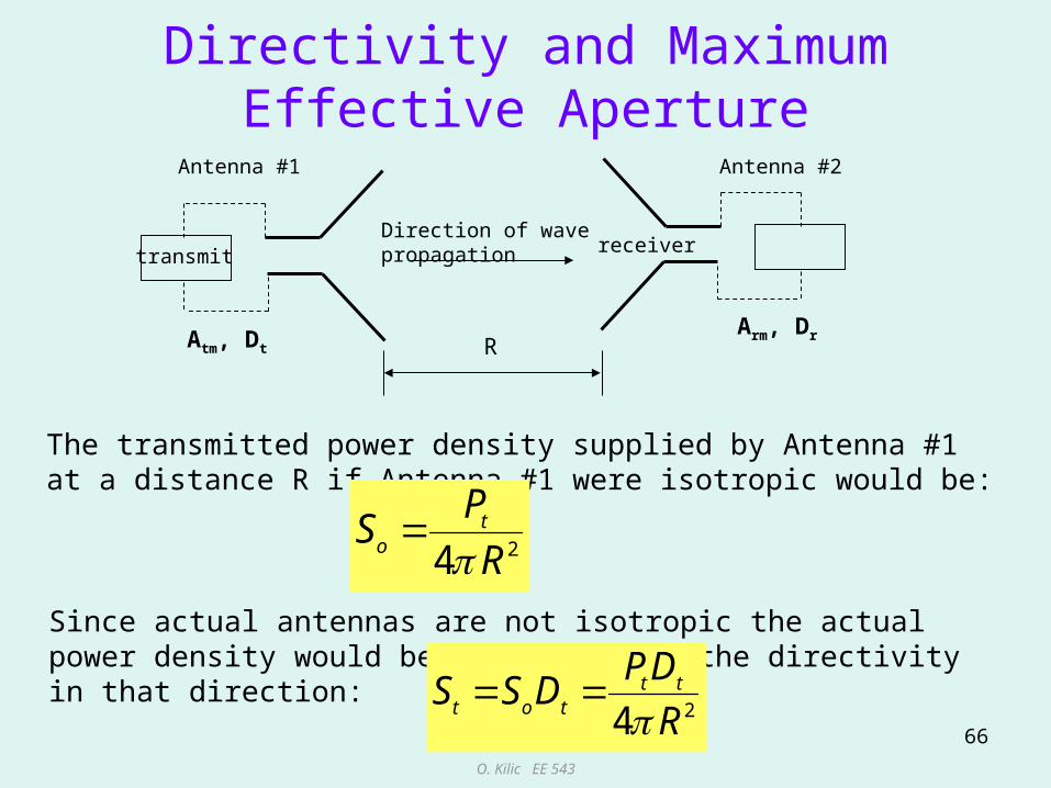
Directivity and Maximum Effective Aperture
Antenna #2
transmit receiver
R
Direction of wave propagation
Antenna #1
Atm, DtArm, Dr
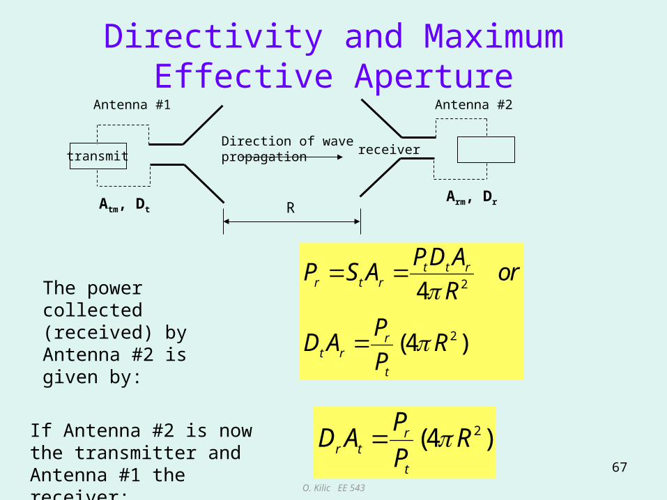
The transmitted power density supplied by Antenna #1 at a distance R if Antenna #1 were isotropic would be:
24t
o
PS
R
Since actual antennas are not isotropic the actual power density would be multiplied by the directivity in that direction:
24t t
t o t
PDS S D
R
O. Kilic EE 543
67
Directivity and Maximum Effective ApertureAntenna #2
transmit receiver
R
Direction of wave propagation
Antenna #1
Atm, DtArm, Dr
The power collected (received) by Antenna #2 is given by:
2
2
4
(4 )
t t rr t r
rt r
t
PD AP S A or
R
PD A R
P
If Antenna #2 is now the transmitter and Antenna #1 the receiver:
2(4 )rr t
t
PD A R
P
O. Kilic EE 543
68
Directivity and Maximum Effective Aperture (no losses)
Antenna #2
transmit receiver
R
Direction of wave propagation
Antenna #1
Atm, DtArm, Dr
2(4 )rt r
t
PD A R
P
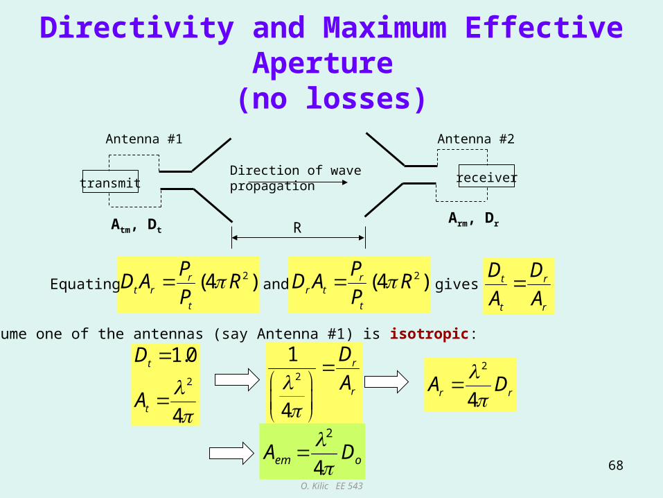
Assume one of the antennas (say Antenna #1) is isotropic:
2(4 )rr t
t
PD A R
PEquating and t r
t r
D D
A Agives
2
1.0
4
t
t
D
A
2
1
4
r
r
D
A
2
4r rA D
oem DA4
2

O. Kilic EE 543
69
Maximum Directivity, Effective Aperture and Beam Solid Angle
14
4
( , ) ( , )4
( , )
4
n n
n A
o
A
U UD
U d
D
oem DA4
2
Also
Therefore 2
em AA For a fixed wavelength Aem and A are inversely proportional.

O. Kilic EE 543
70
Effective Aperture (as a function of direction)
2
2 2
2
4( , )
( , ) ( , )14 4 ( , )
4
( , ) ( , ) ( , )
em o
ne
n
e n em n
A
A D
UA D
U d
A U A U
Can be used for received power when the direction of incident radiation is arbitrary, not necessarily along maximum directivity. Useful when dealing with incoherent radiation form extended sources such as sky or terrain.
O. Kilic EE 543
71
Directivity and Maximum Effective Aperture (include losses)
Antenna #2
transmit receiver
R
Direction of wave propagation
Antenna #1
Atm, DtArm, Dr
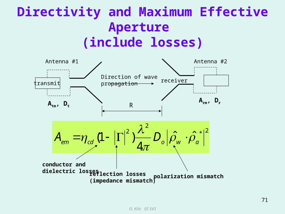
222 *ˆ ˆ(1 )
4em cd o w aA D
conductor and dielectric losses reflection losses
(impedance mismatch)polarization mismatch

O. Kilic EE 543
72
Friis Transmission Equation (no loss)
Antenna #2
Antenna #1
R
transmit
Atm , D
treceiver
Arm, D
r
The transmitted power density supplied by Antenna #1at a distance R and direction (qr,fr) is given by: 2
( , )
4t t t t
t
PDS
R
tt)
rr)
The power collected (received) by Antenna #2 is given by:
2
2 2
2
( , ) ( , ) ( , )
4 4 4
( , ) ( , )4
t t t t t t t t r r rr t r r
rt t t r r r
t
PD PD DP S A A
R R
PD D
P R
O. Kilic EE 543
73
Friis Transmission Equation (no loss)
Antenna #2
Antenna #1
R
transmit
Atm , D
treceiver
Arm, D
r
tt)
rr)
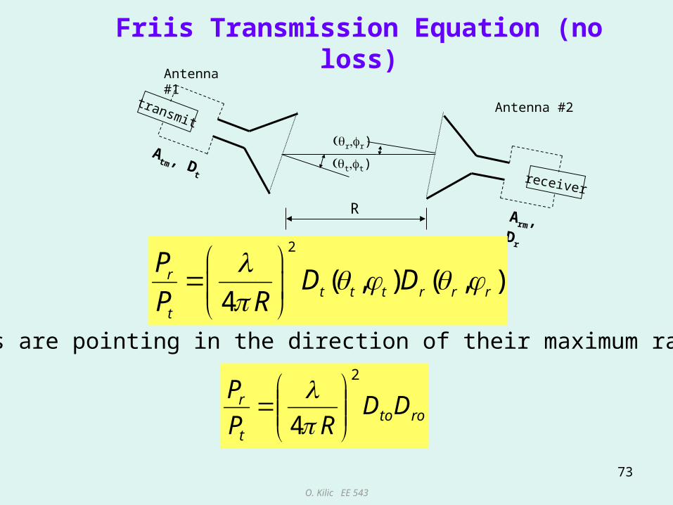
2
( , ) ( , )4
rt t t r r r
t
PD D
P R
If both antennas are pointing in the direction of their maximum radiation pattern:
rotot
r DDRP
P2
4
O. Kilic EE 543
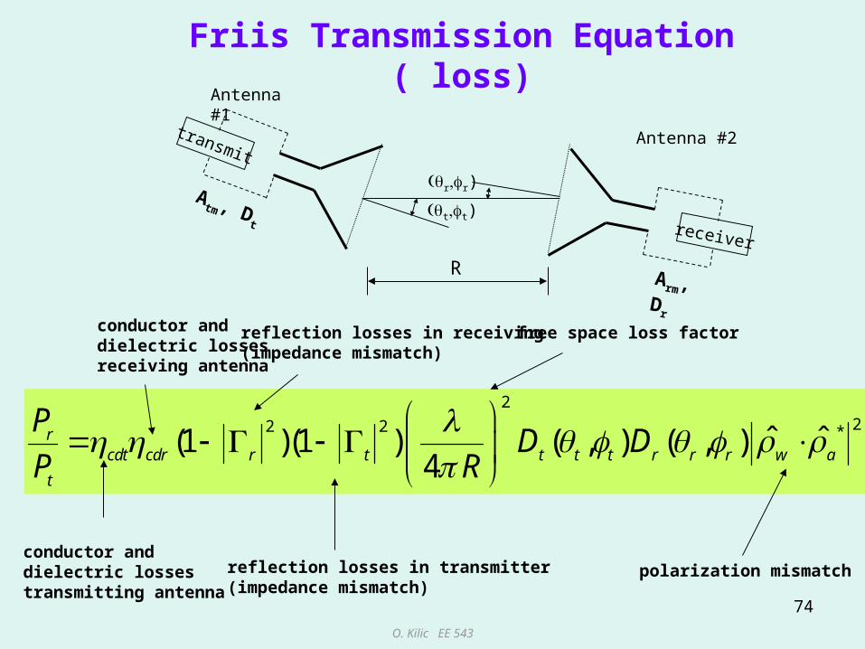
74
Friis Transmission Equation ( loss)
Antenna #2
Antenna #1
R
transmit
Atm , D
treceiver
Arm, D
r
tt)
rr)
222 2 *ˆ ˆ(1 )(1 ) ( , ) ( , )
4r
cdt cdr r t t t t r r r w a
t
PD D
P R
conductor and dielectric lossestransmitting antenna
conductor and dielectric lossesreceiving antenna
reflection losses in transmitter(impedance mismatch)
reflection losses in receiving(impedance mismatch)
polarization mismatch
free space loss factor

O. Kilic EE 543
75
Friis Transmission Equation: Example
Two losses X-band (10.0 GHz) horns are separated by distance of 100. The reflection coefficients measured at the terminals of the transmitting and receiving antennas are 0.1 and 0.2 respectively. The directivities of the transmitting and receiving antennas are 16 dB and 20 dB respectively. Assuming that the power at the input terminals of the transmitting antenna is 3.0 W, and the antennas are aligned for maximum radiation between them and the polarizations are matched, find the power delivered to the receiver.
mWPr 777.4

O. Kilic EE 543
76
References
• Stutzman “Antenna Theory and Design”
• Microwave Remote Sensing, F. T. Ulaby, et.al. Addison-Wesley
• Kraus
• Balanis, “Antenna Theory”.
• EE 540 lectures, Prof. Mirotznik