1. introduction 1 - king county, washington · summary of culvert construction process ... overview...
TRANSCRIPT

Produced by: King County Department of Transportation Roads Services Division Roads Maintenance Section Environmental Unit Special Operations Unit October 25, 2004 Contributing Staff: Stephen Conroy, Senior Ecologist Rob Fritz, Supervising Ecologist Linda Goheen, Crew Lead Janine Johansen, Ecologist John Schut, Equipment Operator Grant Smith, Senior Ecologist Report Coordinator: Michael O’Neil, Senior Engineer Contact any of the above staff at (206) 296-8100


Table of Contents
1. INTRODUCTION...................................................................................................................................................... 1 PURPOSE ........................................................................................................................................................................ 1 SUMMARY OF CULVERT CONSTRUCTION PROCESS ...................................................................................................... 2
Pre-Construction Checklist ....................................................................................................................................... 2 General Construction Procedure .............................................................................................................................. 2
PRESENTATION OF DOCUMENT INFORMATION .............................................................................................................. 3 2. BYPASS CONSTRUCTION ..................................................................................................................................... 4
GRAVITY BYPASS PIPE AND CHANNEL LIMITS AND BENEFITS..................................................................................... 4 PUMP BYPASS LIMITS AND BENEFITS ........................................................................................................................... 5 PROCESS FOR DIVERTING FLOW..................................................................................................................................... 5 BYPASS SEDIMENT REDUCTION .................................................................................................................................... 6
3. CULVERT PLACEMENT......................................................................................................................................... 8 PROCEDURE ................................................................................................................................................................... 8 CHECK DESIGN GRADE TO FIELD CONDITIONS............................................................................................................... 9
4. STREAMBED CONSTRUCTION ......................................................................................................................... 10 BEGINNING STEPS FOR ALL STREAMBED TYPES .......................................................................................................... 10 WETLAND CONNECTOR............................................................................................................................................... 11 RIFFLE MEANDER........................................................................................................................................................ 11 BOULDER CASCADE .................................................................................................................................................... 11 FINISHING STEPS AND COMMENTS ALL STREAM TYPES ............................................................................................. 12 METHODS TO PLACE STREAMBED GRAVEL ................................................................................................................ 12
Closed Lid Structure placement practices............................................................................................................... 12 Open Lid Structures................................................................................................................................................. 13
5. AROUND THE EDGES ....................................................................................................................................... 14 PLACEMENT OF HEAD WALLS ..................................................................................................................................... 14 WALL CONSTRUCTION AND INTERSTITIAL PLANTING................................................................................................ 14 FINAL GRADING AND MULCHING................................................................................................................................ 15 PLANT PROPAGATION FROM CUTTINGS ...................................................................................................................... 15
Cutting Plant Identification..................................................................................................................................... 16 7. MATERIALS......................................................................................................................................................... 18
ITEMS TO CONSIDER IN SELECTION OF STRUCTURE..................................................................................................... 18 STREAM BED................................................................................................................................................................ 19
Streambed Armor and Sub-Grade Gravel Gradation ............................................................................................. 19 Streambed Cobble/Boulder Mix .............................................................................................................................. 19 Method for determining mix of standard materials................................................................................................. 20 Source of Streambed Gravel and Boulders ............................................................................................................. 20
SANDBAGS................................................................................................................................................................... 20 GLOSSARY................................................................................................................................................................... 21

Figures
Figure 1 Boulder Cascade in 10' CMP ............................................................................................................................. 1 Figure 2 Block Net ........................................................................................................................................................... 2 Figure 3 Plastic Sheet Channel......................................................................................................................................... 4 Figure 4 Bypass Construction Process ............................................................................................................................. 5 Figure 5 Straw Bale Energy Dissipater ............................................................................................................................ 6 Figure 6 Base Placement .................................................................................................................................................. 8 Figure 7 Lid Placement .................................................................................................................................................... 8 Figure 8 Checking Grade Using String Line.................................................................................................................... 9 Figure 9 Boulder Cascade Riffle Meander Construction ............................................................................................... 10 Figure 10 Riffle Meander ............................................................................................................................................... 11 Figure 11 Boulder Layer Placement for Cascade........................................................................................................... 11 Figure 12 Methods for Streambed Placement: Bulldozer, Conveyor Belt, Power Barrow.......................................... 13 Figure 13 Completed Bed in Open Lid Structure........................................................................................................... 13 Figure 14 Placing Willow Stakes in Wall ...................................................................................................................... 14 Figure 15 Final Grading ................................................................................................................................................. 15 Figure 16 Temporary Erosion Control ........................................................................................................................... 15 Figure 17 Harvesting Stakes........................................................................................................................................... 16 Figure 18 Plant Identification......................................................................................................................................... 17 Figure 19 Assembly of Structural Plate Pipe ................................................................................................................. 18 Figure 20 Crane working space....................................................................................................................................... 18 Figure 21 Streambed Armor Gravel ................................................................................................................................ 19 Figure 22 Streambed Subgrade Gravel........................................................................................................................... 19

October 25, 2004 2004 Fish Passage Construction
1. Introduction
Purpose This document provides guidance on the construction of fish passable culverts. These recommended construction practices will help reduce turbidity, improve stream habitat performance, and efficiently use resources. Construction crews, biologists, and engineers developed these methods drawing on experience gained during their past construction efforts. This is part of our Endangered Species Act Section 4d program for sharing construction techniques between maintenance crews. Structures discussed here are fish passable culverts. For this discussion, culverts will be considered as structures enclosing the top, sides, and frequently the bottom of the stream corridor. These structures typically range from 4 to 30 feet in width. Although many jurisdictions consider anything spanning greater than 20 feet a bridge we will call all structures discussed herein, culverts. All structures discussed require little, if any, poured in place concrete work. The structures themselves are constructed almost entirely of prefabricated structural elements that can be placed by most maintenance crews.
King Co. DOT Maintenance Environmental Unit - 1–
For these installations, mean annual flows range from 0.25 to 5 cubic feet per second (CFS) and may be perennial or intermittent. This may seem small but they have bankfull widths from 5 to 30 feet and the associated storm flows range from 40 to 500 CFS. To provide a culvert that will pass all flows, sediment, wood, debris and allow fish passage, requires culverts four to eight times larger than those sized for hydraulic capacity alone. At a minimum the width of culverts is 20 percent larger than the bank full channel width plus 2 feet to provide these functions. This document will only lightly discuss design elements. A detailed discussion of the design process is contained in the Washington Department of Fish and Wildlife’s 2003 manual entitled, “Design of Road Culverts for Fish Passage”. Particular attention should be given to the section discussing streambed simulation. This manual is available at http://wdfw.wa.gov/hab/engineer/cm/.
Figure 1 Boulder Cascade in 10' CMP
and Special Operations Unit
October 25, 2004 2004 Fish Passage Construction
Summary of Culvert Construction Process The following provides some basic planning guidelines for use by the construction crews and their leads. Crews that do this work regularly will know these steps in much greater detail than listed here. Those crews that do not regularly perform this type of work will gain guidance making their operations more effective.
Pre-Construction Checklist 1. Order materials.
a) Culvert may take several weeks to fabricate and deliver. b) Find providers for rock, backfill gravel, streambed gravel, etc.
2. Schedule machinery. a) Crane. b) Track hoe. c) Trucks. d) Pumps for bypass and dewatering.
3. Verify utility locations and relocations. 4. Erect temporary road closure signs. 5. Locate bench marks. 6. Layout culvert placement. 7. Set pavement cut limits. 8. Schedule crew, agency inspectors, environmental and archaeological support.
General Construction Procedure Detailed discussions of some construction procedures listed below are provided in later sections. 1. Preconstruction meeting with interested parties (may include but not be limited to supervisor, construction crew,
utilities, and regulatory agencies) to review project expectations. Meet with designers on site to review their project conceptualization, limits of work, and verify horizontal and vertical controls.
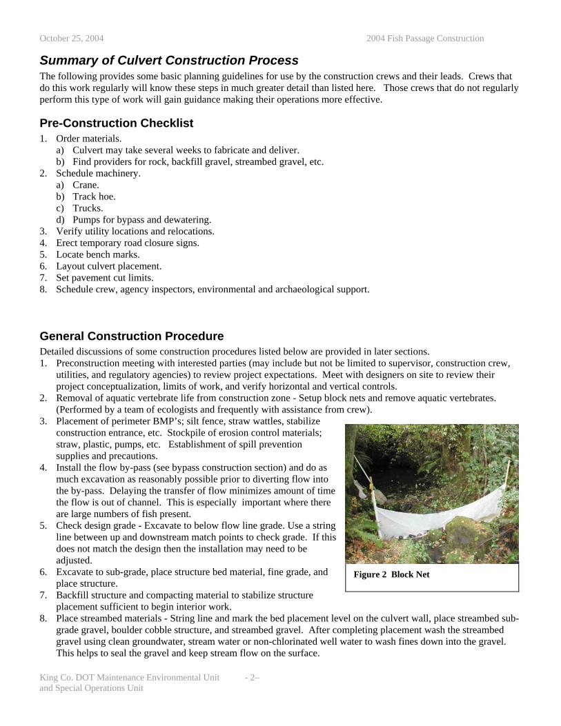
2. Removal of aquatic vertebrate life from construction zone - Setup block nets and remove aquatic vertebrates. (Performed by a team of ecologists and frequently with assistance from crew).
3. Placement of perimeter BMP’s; silt fence, straw wattles, stabilize construction entrance, etc. Stockpile of erosion control materials; straw, plastic, pumps, etc. Establishment of spill prevention supplies and precautions.
Figure 2 Block Net
4. Install the flow by-pass (see bypass construction section) and do as much excavation as reasonably possible prior to diverting flow into the by-pass. Delaying the transfer of flow minimizes amount of time the flow is out of channel. This is especially important where there are large numbers of fish present.
5. Check design grade - Excavate to below flow line grade. Use a string line between up and downstream match points to check grade. If this does not match the design then the installation may need to be adjusted.
6. Excavate to sub-grade, place structure bed material, fine grade, and place structure.
7. Backfill structure and compacting material to stabilize structure placement sufficient to begin interior work.
8. Place streambed materials - String line and mark the bed placement level on the culvert wall, place streambed sub-grade gravel, boulder cobble structure, and streambed gravel. After completing placement wash the streambed gravel using clean groundwater, stream water or non-chlorinated well water to wash fines down into the gravel. This helps to seal the gravel and keep stream flow on the surface.
King Co. DOT Maintenance Environmental Unit - 2– and Special Operations Unit

October 25, 2004 2004 Fish Passage Construction
9. Complete backfilling and compaction. Compaction after moving flow into the structure is not recommended because the vibration often results in sediment plumes.
10. Transition flow to new channel and remove bypass system. 11. Remove block nets. 12. Site clean up and landscape.
Presentation of document information This chapter provided a general overview of construction processes to successfully complete a culvert replacement project. Later sections add detail to some of the processes listed in the general construction procedures followed by guidelines for the ordering of streambed materials.
King Co. DOT Maintenance Environmental Unit - 3– and Special Operations Unit

October 25, 2004 2004 Fish Passage Construction
2. Bypass Construction (item 4 of General Procedure)
Stream flow must be bypassed around the project site prior to the start of in channel work. There are two methods to bypass flows: 1) Gravity pipe bypass 2) Pump bypass In low flow conditions a pump by-pass may be used during the working hours and temporary gravity pipe placed and used for the off hours.
King Co. DOT Maintenance Environmental Unit - 4–
e problem.
Site conditions will determine what type of bypass is best for the project. To effectively minimize turbidity problems the bypass must collect both surface and subsurface flows.
Gravity Bypass Pipe and Channel Limits and Benefits • Gravity bypasses do not require as much
maintenance as the pump bypass, but do require heavy equipment and more time for installation.
• Depending on site conditions, a gravity bypass may be more practical for project that is expected to last longer than a week or when normal flows are greater than ½ CFS.
• Where leakage might be a problem, (e.g. high flow, pipe joints on erosive soils etc), a gravity by-pass pipe should be constructed of ADS N-12 WT pipe or equal. This type of polyethylene pipe has a bell and spigot watertight joint. Where leakage is minor, duct tape wrapping of joints may resolve th
• To minimize disturbance of vegetated stream buffers, stop pipe excavation as soon as practical. Extend pipe above ground as far as possible and/or use a plastic sheeting lined channel, limiting site preparation to vegetation trimming and light hand grading.
Figure 3 Plastic Sheet Channel
• Once installed gravity by-passes require little maintenance and are more dependable than pump systems.
and Special Operations Unit

October 25, 2004 2004 Fish Passage Construction
Pump Bypass Limits and Benefits • For very small flows less than 0.25 CFS, a pump bypass may be a better option than a gravity bypass. • Limited capacity – It is difficult to provide pumping capacity greater than one CFS using typical crew operated
pumps and hose. One CFS through a 6 inch hose will buck similar to a fire hose • Nighttime maintenance -
o 24 hour monitoring by a crewmember is often required to insure continuous pump operation and prevent vandalism and theft. For normal flows there are secure pump systems able to run 24 hours without crew assistance available for rent.
o Alternatively a temporary gravity bypass can be set up using pipe or plastic sheeting. Care shall be used to maintain downstream flow and minimize turbidity when transferring the water to and from the temporary bypass
• Noise may be a factor as well, but there are completely enclosed pumps that are quieter. • If pumps are used, the intake should be screened to prevent fish from being sucked into the pump. The pump
intake should be placed downstream of the block net. • A backup pump should be available on site. • The pump should be capable of pumping the probable high flow anticipated during the construction activity. • If placed in a stream or wetland, the pump should have secondary containment measures to catch fuel or fluid
leaks. This can be as simple as placing the pump in a plastic container or on absorbent pads.
Process for diverting flow
Figure 4 Bypass Construction Process
1. Environmental staff sets block nets, removes fish, and amphibians and then monitors the stream throughout the diversion process for fish or amphibian stranding during channel dewatering. Frequently, fish will be missed during fish exclusion activities and it is essential for environmental staff to be on site during dewatering to catch stranded fish and amphibians.
2. Place erosion control and flow diversion measures where inlet pipe enters channel. Prevent flow from washing construction area and keep flow from entering bypass pipe until the bypass is completed.
3. Construct bypass piping, pumps, and downstream plastic sheet dispersion pad/channel.
4. If bypass flow is from a pump or has high energy, a Straw Bale Dissipation Pool may be needed.
5. Construct initial diversion structure. The purpose of this structure is to divert the bulk of the flow with minimal disturbance to the channel. It is not intended to stop seepage under the structure. This should be installed as close to bypass inlet as practical.
a) Remove larger boulders and cobble from bed. b) Place plastic and sand bags for the structure to a
height that no flow is cascading over the top. 6. Open inlet to allow flow to begin by-passing. Monitor
downstream reaches to make sure the stream does not dry up during the flow transition.
7. Construct cutoff diversion structure immediately downstream of initial structure. This structure is intended to stop seepage as much as practical.
a) If using metal sheets, drive into ground as far as practical or until seepage is cut off.
King Co. DOT Maintenance Environmental Unit - 5– and Special Operations Unit
October 25, 2004 2004 Fish Passage Construction
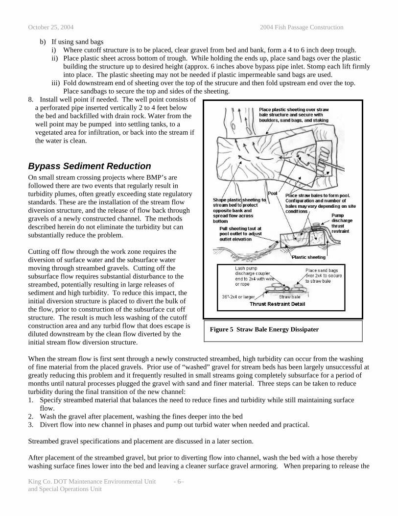
b) If using sand bags i) Where cutoff structure is to be placed, clear gravel from bed and bank, form a 4 to 6 inch deep trough. ii) Place plastic sheet across bottom of trough. While holding the ends up, place sand bags over the plastic
building the structure up to desired height (approx. 6 inches above bypass pipe inlet. Stomp each lift firmly into place. The plastic sheeting may not be needed if plastic impermeable sand bags are used.
iii) Fold downstream end of sheeting over the top of the strucure and then fold upstream end over the top. Place sandbags to secure the top and sides of the sheeting.
8. Install well point if needed. The well point consists of a perforated pipe inserted vertically 2 to 4 feet below the bed and backfilled with drain rock. Water from the well point may be pumped into settling tanks, to a vegetated area for infiltration, or back into the stream if the water is clean.
Figure 5 Straw Bale Energy Dissipater
Bypass Sediment Reduction On small stream crossing projects where BMP’s are followed there are two events that regularly result in turbidity plumes, often greatly exceeding state regulatory standards. These are the installation of the stream flow diversion structure, and the release of flow back through gravels of a newly constructed channel. The methods described herein do not eliminate the turbidity but can substantially reduce the problem.
King Co. DOT Maintenance Environmental Unit - 6–
ff
Cutting off flow through the work zone requires the diversion of surface water and the subsurface water moving through streambed gravels. Cutting off the subsurface flow requires substantial disturbance to the streambed, potentially resulting in large releases of sediment and high turbidity. To reduce this impact, the initial diversion structure is placed to divert the bulk of the flow, prior to construction of the subsurface cut ostructure. The result is much less washing of the cutoff construction area and any turbid flow that does escape is diluted downstream by the clean flow diverted by the initial stream flow diversion structure. When the stream flow is first sent through a newly constructed streambed, high turbidity can occur from the washing of fine material from the placed gravels. Prior use of “washed” gravel for stream beds has been largely unsuccessful at greatly reducing this problem and it frequently resulted in small streams going completely subsurface for a period of months until natural processes plugged the gravel with sand and finer material. Three steps can be taken to reduce turbidity during the final transition of the new channel: 1. Specify streambed material that balances the need to reduce fines and turbidity while still maintaining surface
flow. 2. Wash the gravel after placement, washing the fines deeper into the bed 3. Divert flow into new channel in phases and pump out turbid water when needed and practical. Streambed gravel specifications and placement are discussed in a later section. After placement of the streambed gravel, but prior to diverting flow into channel, wash the bed with a hose thereby washing surface fines lower into the bed and leaving a cleaner surface gravel armoring. When preparing to release the
and Special Operations Unit

October 25, 2004 2004 Fish Passage Construction
flow into the channel remove the subsurface flow cutoff structure first and then use the initial stream diversion structure to control the release of flow into the channel. Remove a small number of sand bags at a time, wait for the flow to clear and then remove a few more; continue the process until all of the flow is in the new channel and then remove the stream bypass. Continuing partial flow through the bypass during re-watering as described above helps dilute turbidity released from the new channel. A small pump may also be used at the culvert outlet to carry initial turbid flows from the culvert to an infiltration or treatment area. Monitor downstream reaches during this flow transition to ensure that flow is maintained.
King Co. DOT Maintenance Environmental Unit - 7– and Special Operations Unit

October 25, 2004 2004 Fish Passage Construction
3. Culvert Placement (Expansion of item 5 of General Construction Procedure)
King Co. DOT Maintenance Environmental Unit - 8–
Procedure 1. Set up on-site construction material stock piles if area
available. 2. Excavate to rough grade and haul off waste. 3. Verify plans: check plan grade to onsite conditions. Determine
if design layout matches the existing stream grade. If not, contact the designers.
4. Finish rough grade. Place and fine grade culvert sub base material. Use of pea gravel is not recommended for the sub base. Because of the open texture of the material, stream flow frequently finds a path to sub base and flows through it under the box rather than on the streambed surface. The selected subgrade material should have sufficient fines to prevent this type of piping of flows under the structure.
5. Layout culvert placement. 6. Place culvert or base section of box if in two parts. If using a structure
requiring a crane, completion of the subgrade and arrival of the crane must be well planned. Cranes have high rental rates and are costly to leave idle on site.
7. Seal structure if required 8. Begin backfill. 9. Construct streambed (see later section for details). 10. Place and seal culvert lid. 11. Construct headwall if required and complete backfill and roadway grading. If using a concrete box structure with a removable lid you must make the designers aware that they structure needs to have a recessed lip or weld plates to keep the lid from moving after placement. Even with the use of sealants the lid may turn if machinery is maneuvering on top of them. There have also been problems with culverts placed on sloping grades with the lids being vibrated out of position during compaction of fill and pavement.
Figure 6 Base Placement
Figure 7 Lid Placement
and Special Operations Unit

October 25, 2004 2004 Fish Passage Construction
Check design grade to field conditions (Item 5 of General Construction Procedure and Item 4 of Culvert Placement Procedure)
Figure 8 Checking Grade Using String Line
Because field conditions may change between the time of a design survey and construction of the culvert it is important to check the culvert design grade to the actual stream grade. • Excavate below plan stream invert but above culvert
foundation grade. • Run string line between up and down stream
match inverts. The invert of the culvert will usually be a minimum of 2 feet below the string line at the downstream end.
King Co. DOT Maintenance Environmental Unit - 9–
oulder
If elevation of string line in culvert zone does not match planned stream grade within approximately 0.3 feet at inlet or outlet then contact designers. Foundation grade may need to be raised or lowered or grade drop habitat structures added at either end: i.e. log or bcascade.
and Special Operations Unit
October 25, 2004 2004 Fish Passage Construction
4. Streambed Construction
King Co. DOT Maintenance Environmental Unit - 10–
ructures:
Figure 9 Boulder Cascade Riffle Meander Construction
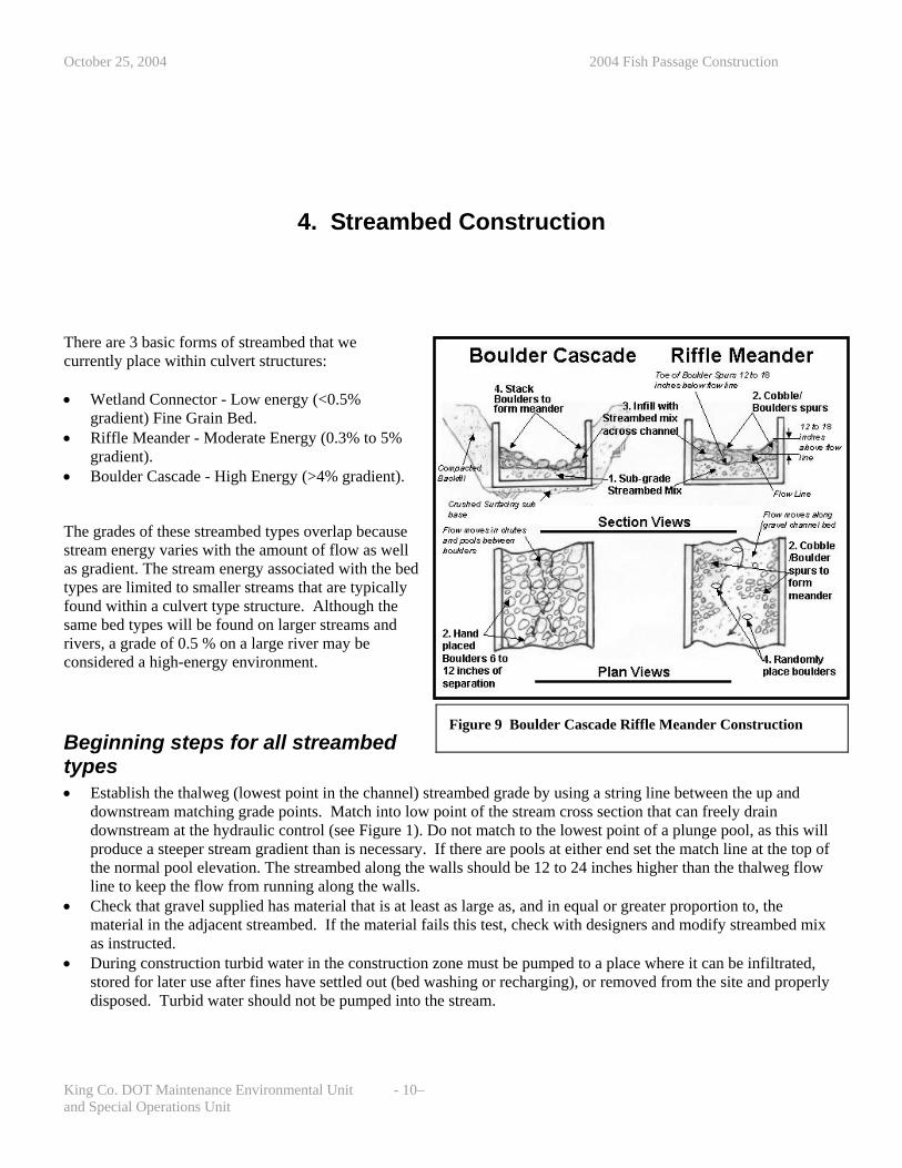
There are 3 basic forms of streambed that we currently place within culvert st • Wetland Connector - Low energy (<0.5%
gradient) Fine Grain Bed. • Riffle Meander - Moderate Energy (0.3% to 5%
gradient). • Boulder Cascade - High Energy (>4% gradient).
The grades of these streambed types overlap because stream energy varies with the amount of flow as well as gradient. The stream energy associated with the bed types are limited to smaller streams that are typically found within a culvert type structure. Although the same bed types will be found on larger streams and rivers, a grade of 0.5 % on a large river may be considered a high-energy environment.
Beginning steps for all streambed types • Establish the thalweg (lowest point in the channel) streambed grade by using a string line between the up and
downstream matching grade points. Match into low point of the stream cross section that can freely drain downstream at the hydraulic control (see Figure 1). Do not match to the lowest point of a plunge pool, as this will produce a steeper stream gradient than is necessary. If there are pools at either end set the match line at the top of the normal pool elevation. The streambed along the walls should be 12 to 24 inches higher than the thalweg flow line to keep the flow from running along the walls.
• Check that gravel supplied has material that is at least as large as, and in equal or greater proportion to, the material in the adjacent streambed. If the material fails this test, check with designers and modify streambed mix as instructed.
• During construction turbid water in the construction zone must be pumped to a place where it can be infiltrated, stored for later use after fines have settled out (bed washing or recharging), or removed from the site and properly disposed. Turbid water should not be pumped into the stream.
and Special Operations Unit

October 25, 2004 2004 Fish Passage Construction
Wetland Connector 1. Place streambed mix to the flow line. 2. Provide additional streambed armor mix along the channel edges to form meanders, with a continuous upland area
along both walls above high water line. This provides passage under the road for amphibians and small mammals. Typically this design will be used where roads cross wetlands and the culvert is the hydrologic connection between the bisected parts of the wetland. The up and downstream beds are made up of fine-grained soils with very little gravel. In some cases the culvert may be left to fill itself. If a channel is constructed inside a wetland connector, its primary goals are to allow for passage of fish, amphibians, and terrestrial animals.
Riffle Meander 1. Place a layer of sub grade streambed mix to within 12 to
18 inches of the thalweg flow line.
King Co. DOT Maintenance Environmental Unit - 11–
han
o
2. Construct boulder/cobble spurs, or clusters, along the walls. The largest boulder does not need to be more ttwice the size of the largest boulder used in the streambed mix. The spurs should be constructed to 12 t24 inches above the thalweg flow line along the walls then tapering downward across the channel. The clusters should not protrude more than 40% of the distance across the culvert.
3. Place streambed armor gravel to the thalweg flow line across the bed and infill the voids in the boulder spurs.
4. Place boulders and cobbles randomly on the bed to increase the stream complexity.
During high flow the streambed digs down, scouring gravel below its normal bed level and then it refills again with fresh gravel from upstream as the flow rate falls. To prevent the boulders from being undercut and rolled away during scouring flows, their base must be deeper than the depth of maximum scour. This depth is also the level that the initial layer of streambed subgrade mix typically is placed in step 1. The placement of boulder spurs along the channel edges forces the stream to meander throughout the length of the culvert, varying the depth and providing pools and eddies throughout the structure. This improves the ability of aquatic species to move through the structure for a range of flows.
Figure 10 Riffle Meander
Figure 11 Boulder Layer Placement for Cascade
Boulder Cascade 1. Place a layer of sub grade streambed mix to an elevation
within 12 to 18 inches of the flow line targeting a level that is deeper than the estimated maximum depth of scour (see above).
2. Place a layer of boulders about 6 to 18 inches apart. At a minimum these boulders should be approximately one to two times the size of the largest boulder used in the streambed mix.
3. Infill the spaces with streambed mix. 4. Form the thalweg by placing boulder clusters along the
wall to move the stream flow back and forth. 5. Infill the clusters with streambed mix.
and Special Operations Unit
October 25, 2004 2004 Fish Passage Construction
During high flow the gravel will wash between the boulders with some of the larger streambed mix rock lodging or bridging the spaces between the boulders, resulting in a complex series of chutes and pools. The result is a structurally stable channel resulting as the gravel/cobble matrix lock the boulders together.
Finishing Steps and Comments all Stream Types 1. Wash the gravel surface prior to diverting flow into new channel. The gravel can be washed in place with water
stored from construction operation, with clean ground water, by partial re-watering with stream flow, or with imported non-chlorinated well water.
2. Use external water or a small portion of stream flow to charge ground water in the streambed. 3. Slowly divert flow into the new channel a small amount at a time. Because of high turbidity, the first of these
flows may need to be pumped out of the channel to a settling tank or infiltration area. 4. As the turbidity reduces to a point that mixing action with down stream flow makes the resulting turbidity
negligible, divert more stream flow into the channel. 5. When turbidity reduces to acceptable levels repeat the previous step until all flow is diverted. • Do not divert flow into new channel until roadway compaction is complete. Complete as much construction
as possible before diverting flow. • Remove the diversion structure in the following order: well point, cutoff structure, and lastly the initial structure
in stages. • Use the initial structure to control the release of flow allowing no more than a third of the flow at a time into the
new channel and waiting for the flow to clear before adding additional flow. • Maintain flow in downstream channel at all times. The goal of these steps is to reduce turbidity released by the stream washing through the new gravel bed. The initial (step1) streambed washing helps clear the bed of some of the surface fines by washing them into the bed and helping seal it to prevent excessive subsurface flow. The later steps will result in some turbidity moving downstream but by diverting flow in stages the intensity of the turbidity plume is reduced. The steps outlined above for the introduction of water to the new culvert with low turbidity may require 4 to 8 hours or more to complete, therefore it is best to begin bypass removal in the morning.
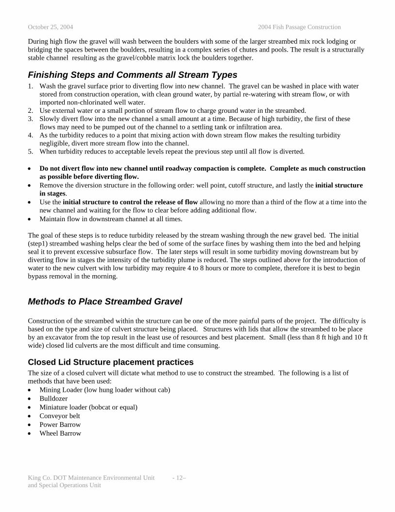
Methods to Place Streambed Gravel Construction of the streambed within the structure can be one of the more painful parts of the project. The difficulty is based on the type and size of culvert structure being placed. Structures with lids that allow the streambed to be place by an excavator from the top result in the least use of resources and best placement. Small (less than 8 ft high and 10 ft wide) closed lid culverts are the most difficult and time consuming.
Closed Lid Structure placement practices The size of a closed culvert will dictate what method to use to construct the streambed. The following is a list of methods that have been used: • Mining Loader (low hung loader without cab) • Bulldozer • Miniature loader (bobcat or equal) • Conveyor belt • Power Barrow • Wheel Barrow
King Co. DOT Maintenance Environmental Unit - 12– and Special Operations Unit

October 25, 2004 2004 Fish Passage Construction
Figure 12 Methods for Streambed Placement: Bulldozer, Conveyor Belt, Power Barrow
No matter which method is used, there must be advance planning because the stream must be entirely built in layers from bottom to top as material is placed through the length of the culvert (initial sub grade placement, boulder placement, final streambed mix layer, etc). Because of the limited space within the culvert, much of the placement must be done by hand once the material is delivered into the culvert. Conveyor belts of the right size and power to deliver a variety of material sizes are difficult to find. They deliver material to one point that then must be handled into position. Each movement of the belt requires resetting of support bracing. This method also requires good access to the inlet and outlet in order to insert the conveyor inside the culvert. Use of any petroleum-powered vehicle within the structure requires the placement of ventilation equipment. This usually consists of large generator-powered fans at the inlet and outlet.
Open Lid Structures For placing streambed material, open lidded structures are preferred. After setting the base section, the streambed material and boulders can easily and quickly be placed by a trackhoe. After the placement of streambed is complete the lid can be placed and the structure backfilled and covered. This eliminates days of work and greatly improves quality of work over that of closed lid structures. There are two types of open lidded structures available: • Four sided concrete box with removable lid. The structure
comes in two parts; a base section that includes floor and walls, with the second piece being the top slab. These are available in widths up to 35 feet. Due to their weight, these culverts frequently require cranes or a large trackhoe for placement.
• Metal arch with concrete foundation. The foundation may be a stem wall with footings or a concrete base section similar to the base section of the 4 sided box structure. The height of the walls needs to be constructed above the maximum level of the streambed material to allow placement of this material prior to installing the lid.
Figure 13 Completed Bed in Open Lid Structure
King Co. DOT Maintenance Environmental Unit - 13– and Special Operations Unit

October 25, 2004 2004 Fish Passage Construction
5. Around the Edges
Placement of Head walls Use of headwalls and rock-lined banks must be minimized. Regulatory agencies are looking for a stream in as natural setting as possible. Rock walls along the channel are discouraged. Everything else can look great, but the rock walls remind agencies of too many river systems that have been largely rocked and leveed, greatly reducing biological functions of the banks. Head walls are necessary for the stability of the road but only use them to the extent necessary. Rounded boulders placed in clusters along a bank to deflect flows are normally acceptable, but do not rock line the banks. Designs for maintenance frequently are based on a minimum amount of survey information. This can make it difficult for crews to determine where cut and fill lines will fall. If it appears that more wall is needed than indicated on the plans, work with the ecologist and engineer to modify the placement. If a wall appears to be excessive and cannot be reasonably justified, regulatory agencies will often require its removal. If there are issues with the head wall location they should be discussed in design review, and prior to the pre construction conference. The construction crew should review the plans with their supervisor. The supervisor or crew lead should attend the pre-construction meeting to discuss crew concerns and comments.
Figure 14 Placing Willow Stakes in Wall
Wall Construction and Interstitial Planting Construction methods for a headwall range between those of a rockery and revetment. Normally the construction of the headwall requires the interstitial layering of vegetation cuttings. Willow cuttings are 2 to 3 feet in length and ½ to 2 inch in diameter. Throughout wall installation the rocks are selected to decrease in size from subgrade to final grade. After a layer of rock is placed, spread a light layer of top soil, place willow slips or other cutting as required, water, and then place the next layer repeating the procedure. • The base rock is usually below final grade and topsoil and
willow are not installed until a rock layer is placed that will be above the finish grade.
• Following installation of the base course the first soil lift is placed.
• Willow stakes are placed in the topsoil prior to the next lift of rock. The willows stakes are locked in place beneath the next lift of rock.
• The final lift of soil and willow is installed at the base of the road shoulder, and is setback far enough from the culvert end to prevent shoulder material from falling into the stream.
King Co. DOT Maintenance Environmental Unit - 14– and Special Operations Unit
October 25, 2004 2004 Fish Passage Construction
• The last rock lift is installed to support the base of the shoulder. • Not all sites are suitable for cuttings. Other plants, such as salmonberry, can be planted in the first winter after
construction. • Cuttings may need to be watered if dry conditions persist.
King Co. DOT Maintenance Environmental Unit - 15–
nlet
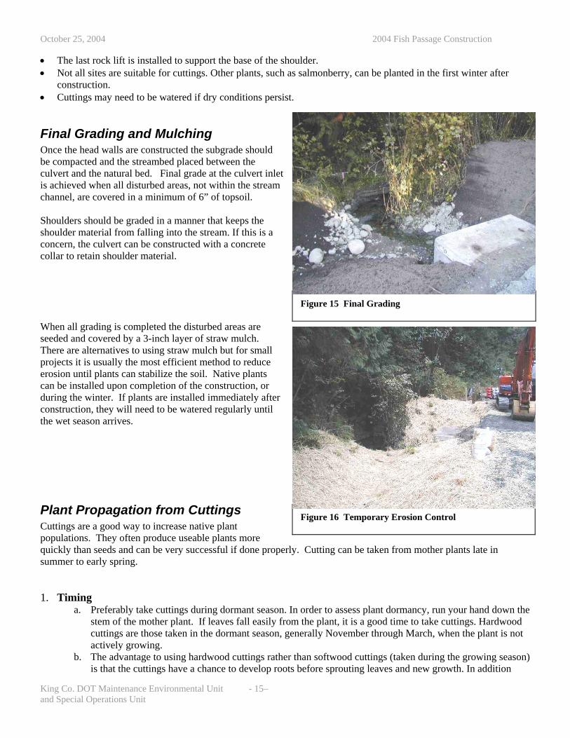
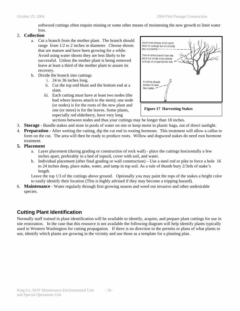
Final Grading and Mulching Once the head walls are constructed the subgrade should be compacted and the streambed placed between the culvert and the natural bed. Final grade at the culvert iis achieved when all disturbed areas, not within the streamchannel, are covered in a minimum of 6” of topsoil. Shoulders should be graded in a manner that keeps the shoulder material from falling into the stream. If this is a concern, the culvert can be constructed with a concrete collar to retain shoulder material. When all grading is completed the disturbed areas are seeded and covered by a 3-inch layer of straw mulch. There are alternatives to using straw mulch but for small projects it is usually the most efficient method to reduce erosion until plants can stabilize the soil. Native plants can be installed upon completion of the construction, or during the winter. If plants are installed immediately after construction, they will need to be watered regularly until the wet season arrives.
Plant Propagation from Cuttings Cuttings are a good way to increase native plant populations. They often produce useable plants more quickly than seeds and can be very successful if done properly. Cutting can be taken from mother plants late in summer to early spring.
Figure 15 Final Grading
Figure 16 Temporary Erosion Control
1. Timing
a. Preferably take cuttings during dormant season. In order to assess plant dormancy, run your hand down the stem of the mother plant. If leaves fall easily from the plant, it is a good time to take cuttings. Hardwood cuttings are those taken in the dormant season, generally November through March, when the plant is not actively growing.
b. The advantage to using hardwood cuttings rather than softwood cuttings (taken during the growing season) is that the cuttings have a chance to develop roots before sprouting leaves and new growth. In addition
and Special Operations Unit
October 25, 2004 2004 Fish Passage Construction
softwood cuttings often require misting or some other means of moistening the new growth to limit water loss.
2. Collection
King Co. DOT Maintenance Environmental Unit - 16–
a. Cut a branch from the mother plant. The branch should range from 1/2 to 2 inches in diameter. Choose shoots that are mature and have been growing for a while. Avoid using water shoots they are less likely to be successful. Unless the mother plant is being removed leave at least a third of the mother plant to assure its recovery.
b. Divide the branch into cuttings i. 24 to 36 inches long.
ii. Cut the top end blunt and the bottom end at a slant.
iii. Each cutting must have at least two nodes (the bud where leaves attach to the stem); one node (or nodes) is for the roots of the new plant and one (or more) is for the leaves. Some plants, especially red elderberry, have very long sections between nodes and thus your cuttings may be longer than 18 inches.
Figure 17 Harvesting Stakes
3. Storage - Bundle stakes and store in pools of water on site or keep moist in plastic bags, out of direct sunlight. 4. Preparation - After wetting the cutting, dip the cut end in rooting hormone. This treatment will allow a callus to
form on the cut. The area will then be ready to produce roots. Willow and dogwood stakes do need root hormone treatment.
5. Placement a. Layer placement (during grading or construction of rock wall) - place the cuttings horizontally a few
inches apart, preferably in a bed of topsoil, cover with soil, and water. b. Individual placement (after final grading or wall construction) – Use a steel rod or pike to force a hole 16
to 24 inches deep, place stake, water, and tamp in top soil. As a rule of thumb bury 2/3rds of stake’s length.
Leave the top 1/3 of the cuttings above ground. Optionally you may paint the tops of the stakes a bright color to easily identify their location (This is highly advised if they may become a tripping hazard).
6. Maintenance - Water regularly through first growing season and weed out invasive and other undesirable species.
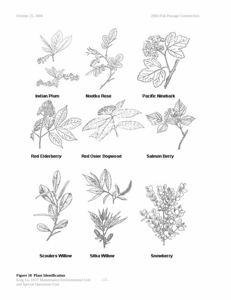
Cutting Plant Identification Normally staff trained in plant identification will be available to identify, acquire, and prepare plant cuttings for use in site restoration. In the case that this resource is not available the following diagram will help identify plants typically used in Western Washington for cutting propagation. If there is no direction in the permits or plans of what plants to use, identify which plants are growing in the vicinity and use those as a template for a planting plan.
and Special Operations Unit
October 25, 2004 2004 Fish Passage Construction
King Co. DOT Maintenance Environmental Unit - 17– Figure 18 Plant Identification
and Special Operations Unit

October 25, 2004 2004 Fish Passage Construction
7. Materials
Items to consider in selection of structure
King Co. DOT Maintenance Environmental Unit - 18–
Crews constructing culverts need to be active in the selection of the type of structure used at a site. The type of structure selected will greatly impact the difficulty, construction duration, and cost of a facility.
• Time for assembly. o Structural plate structures require a
substantial amount of time to bolt together. An 80 foot long, 16 foot diameter structure required 5000 bolts, employing a crew of 4 for two weeks.
o Most larger prefabricated structures require a 4 to 8 week manufacture lead time.
• Access: o For crane; particularly for concrete
structures. o Delivery vehicles. Trucks carrying heavy
structural elements may need to back in for substantial distances.
• Electrical line clearances required for operation of equipment lifting structure into place.
• Weight of structure. Particularly a problem for concrete structures (Frequently the crane will set the base section and an excavator will set the lids after the placement of the streambed. The excavator must be sized to lift the lids otherwise maintaining the crane on site will become very expensive.) There may be weight limits on roads, bridges, and ferries that can prohibit the use of concrete structures.
• Ability to place the streambed as specified. To many agencies this is the most important part of the project. A bad job here is similar to building a dream home exterior and then finishing the interior with cardboard and sawdust. The more difficult the placement of material the less likely the crews will be able to produce the desired results. Use open lidded structures for best results.
Figure 19 Assembly of Structural Plate Pipe
Figure 20 Crane working space
• Familiarity of crews with structure type.
and Special Operations Unit

October 25, 2004 2004 Fish Passage Construction
If using a concrete box structure with a removable lid you must make the designers aware that they structure needs to have a recessed lip or weld plates to keep the lid from moving after placement. Even with the use of sealants the lid may turn if machinery is maneuvering on top of them. There have also been problems with culverts placed on sloping grades with the lids being vibrated out of position during compaction of fill and pavement.
Stream bed The following specifications were developed to maximize streambed biological functions, maintain surface flow and minimize turbidity. While providing these functions, it also is a recipe that gravel mine sources can easily understand and produce. The gravel shall be produced from rounded stone, no crushed stone. 1) Streambed gravel is broken into sizing categories:
King Co. DOT Maintenance Environmental Unit - 19–
obble/
e
• Base streambed gravel - 100% less than 4 inches
• Streambed cboulder - 4 inches to the largest sizneeded
2) The Base streambed gravel will be provided in two classifications:
• Streambed Armor Gravel - 100% passing the 4 inch and 0 to 5 % passing the 200 sieve.
• Streambed Sub-grade Gravel - 100% passing the 4 inch and 5 to 10% passing the 200 sieve.
Figure 21 Streambed Armor Gravel
Figure 22 Streambed Subgrade Gravel
Streambed Armor and Sub-Grade Gravel Gradation Detailed specifications for these standards products follow: Streambed Armor Gravel Sieve Size % Passing4” Square 100 3” Square 88-100 1-1/2” Square 60-86 ¾” Square 41-65 3/8” 27-49 No. 4 16-38 No. 40 10-20 U.S. No. 200 0-5
Streambed Sub-grade Gravel Sieve Size % Passing4” Square 100 3” Square 88-100 1-1/2” Square 62-88 ¾” Square 42-68 3/8” 32-54 No. 4 22-44 No. 40 15-30 U.S. No. 200 5-10
Streambed Cobble/Boulder Mix Varies from 36" to 4" diameter boulder/cobble rounded rock (no riprap or quarry spalls or artificially fractured rock). The mix shall be well graded from the maximum dimension requested down to 4”. When ordered, this material should
and Special Operations Unit
July 19, 2004 2004 Fish Passage Construction
be mixed with either the Streambed Armor Gravel mix or the Streambed Sub-grade Gravel Mix to produce the final streambed materials. Note: The cobble/boulder material will need to be visually graded; there is no standard equipment for mixing or sorting this size of material. The gravel pits typically have stockpiles of over sized material sorted in approximate size ranges. We should not be concerned if some of the cobble/boulder material provided exceeds the maximum specified size range. A few larger pieces will add to the stream structure.
Method for determining mix of standard materials The streambed armor gradation was derived using a sizing sequence to minimize void space after applying Washington Department of fish and Wildlife (WDFW) guidelines. The sub-grade material varies from this criterion, below the #4 sieve, where finer material is greatly increased to reduce bed infiltration. The placed streambed material will be a mix of these standard materials. To specify the mix of material, review the WDFW derived gradation and pick the gradation percentage that requires material greater than 4 inches in size. The percent of material below that point will be made of the Base Streambed gravel and the amount above that is made of Streambed Cobble/Boulder. Because the mixing of these materials is rough, the first batches should be viewed and if the mix appears too coarse or too fine then the mix should be amended to develop an acceptable recipe for mixing of material. The gravel mine operator should be encouraged to keep a record of the relative proportions of source materials so that suitable mixes can be duplicated in the future.
Source of Streambed Gravel and Boulders Most pit sites have sufficient screened materials to produce the base streambed gravels. A common source for fines at pit sites is the fine wash pond cake material. Larger rounded boulders can be found at many pit sites but they may need advance notices to set aside material from their oversized stock. Unless they are notified, the oversized material is usually broken and crushed, or buried.
Sandbags If sand bags are to be removed following the completion of construction, use woven synthetic fiber or plastic bags. Burlap bags degrade very rapidly, frequently in as little as two weeks of submergence will leave them is such a weakened condition that they will burst when moved, resulting in downstream turbidity problems. When using non-biodegradable products it is important that these products be removed from the site following construction to avoid becoming a habitat hazard. When permanently leaving bags in place to reinforce a stream edge until planting can stabilize a site or other similar purpose use burlap or other biodegradable fabric.
King Co. DOT Maintenance Environmental Unit - 20 –

July 19, 2004 2004 Fish Passage Construction
Glossary Armor gravel: A streambed mix of gravel that contains 0-5% fines passing the #200 sieve and 10-20% passing the #40 sieve. This mix is used as an upper layer during streambed construction. Bankfull channel width: The zone that extends to the edge of the rooted vegetation on each side. Characterized by the start of perennial vegetation, and often by a change in the channel side slope to a more horizontal grade. The stage at which stream flow enters the floodplain. Boulder cascade: A stream channel of greater than 4% gradient where the substrate is composed of large boulders that are immobile during most flows. Pools are small, shallow and flow is often turbulent. Hydraulic control: The streambed at the outlet of a pool that maintains the water surface elevation within the pool. A streambed feature that creates a backwater in an area of the channel. Monolithic channel: A stream channel characterized by the massiveness, rigidity and uniformity of its substrate. Plunge Pool: A pool created by vertical scour, usually associated with a waterfall or culvert outlet. Residual Pool: A pool that exists at extreme low flow and in which the water surface is maintained by the hydraulic control. Riffle Meander: A stream channel of 0.5% to 4% gradient in which the vertical grade features are provided by pools and riffles, and which demonstrates lateral sinuosity. Sub-grade gravel: A streambed gravel mix containing contains 5-10% fines passing the #200 sieve and 15-30% passing the #40 sieve. This materiel is placed underneath the armor gravel layer and is designed to help support surface flows by providing a rapid sealing of interstitial spaces. Thalweg: The stream path that the lowest flow will follow; usually in the form of a deep trough in the cross section view of the channel
King Co. DOT Maintenance Environmental Unit - 21 –