1 introduction -...
TRANSCRIPT

Long and Fast Up/Down CountersPushpinder Kaur CHOUHAN
6th Jan, 2003
1 Introduction
Circuits for counting both forward and backward events are frequently usedin computers and other digital systems. Digital clocks and watches are ev-erywhere, timers are found in a range of appliances from microwave ovensto VCRs and counters for other reasons are found in everything from auto-mobiles to test equipment. Since a counter circuit must remember its paststates, it has to possess memory. For this purpose flip-flops are used. Thenumber of flip-flops used and how they are connected determine the numberof states and the sequence of the states that the counter goes through in eachcomplete cycle. Although we will see many variations on the basic counter,they are all fundamentally very similar.
The paper presents recent advances in the design of constant-time up/downcounters in the general context of fast counter design. An overview of ex-isting techniques for the design of long and fast counters reveals severalmethods closely related to the design of fast adders, as well as some tech-niques that are only valid for counter design. The main idea behind thenovel up/down counters is to recognize that the only extra difficulty with anup/down counter is when the counter changes direction from counting upto counting down (and vice-versa). For dealing with this difficulty, the newdesign uses a shadow register for storing the previous counter state. Whencounting only up or only down, the counter functions like a standard up-onlyor down-only constant time counter, but, when it changes direction insteadof trying to compute the new value (which typically requires carry propa-gation), it simply uses the contents of the shadow register which containsthe exact desired previous value. An alternative approach for restoring theprevious state in constant time is to store the carry bits in a Carry/Borrowregister.
The simplest type of counter is the Binary Counter. The 2-bit ripplecounter circuit has four different states, each one corresponding to a countvalue. Similarly, a counter with n flip-flops can have 2n states. The numberof states in a counter is known as its mod number. Thus a 2-bit counteris a mod-4 counter.A mod-n counter may also described as a divide-by-ncounter because it can also be used to divide the input pulse frequency byfactor of n(the mod number). Thus, the mod-4 counter is an example of adivide-by-4 counter. In general we can write counter as binary modulo-2N
N-bit counter where the value s(t) of the counter is incremented by one ineach clock cycle: s(t+1)=s(t)mod2N
1

Besides this basic behavior, most counter types have several other fea-tures, the most important ones being illustrated with the help of a “black-box” model as in Figure 1.
Figure 1. “Black-box” generic counter model with the most common control signals.
1. Resettable - The counter value is reset to all zeros when the RESET inputis active.2. Loadable - The counter is loaded with the N-bit value at the In inputlines when the LOAD input is active.3. Reversible - The counter counts “up” (increments) when the UP/DOWNinput signal is inactive and counts“down”(decrements) when the UP/DOWNinput signal is active.4. Count-enable — The counter increments every clock cycle only when theCNT input is active.5. Terminal Count — TC output signal active when the counter reachesthe maximum value (all ones) counting up or reaches the minimum value(all zeros) when counting down.6. Readable on-the-fly — The counter state (Out) can be read reliably with-out stopping the clock. Ideally, this sampling rate should be equal to theclock rate.
2 Counters
2.1 Asynchronous Counter
A three-bit asynchronous counter is shown in Figure 2. The external clock isconnected to the clock input of the first flip-flop (FF0) only. So, FF0 changesstate at the falling edge of each clock pulse, but FF1 changes only whentriggered by the falling edge of the Q output of FF0 and so on. Because ofthe inherent propagation delay through a flip-flop, the transition of the inputclock pulse and a transition of the Q output of FF0 can never occur at exactly
2
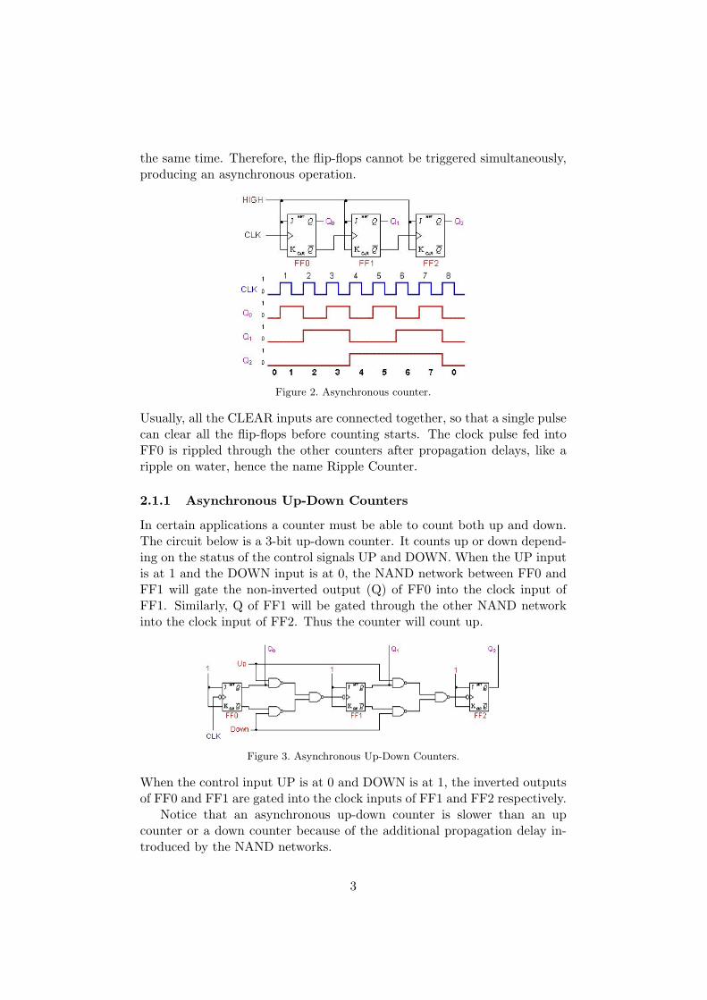
the same time. Therefore, the flip-flops cannot be triggered simultaneously,producing an asynchronous operation.
Figure 2. Asynchronous counter.
Usually, all the CLEAR inputs are connected together, so that a single pulsecan clear all the flip-flops before counting starts. The clock pulse fed intoFF0 is rippled through the other counters after propagation delays, like aripple on water, hence the name Ripple Counter.
2.1.1 Asynchronous Up-Down Counters
In certain applications a counter must be able to count both up and down.The circuit below is a 3-bit up-down counter. It counts up or down depend-ing on the status of the control signals UP and DOWN. When the UP inputis at 1 and the DOWN input is at 0, the NAND network between FF0 andFF1 will gate the non-inverted output (Q) of FF0 into the clock input ofFF1. Similarly, Q of FF1 will be gated through the other NAND networkinto the clock input of FF2. Thus the counter will count up.
Figure 3. Asynchronous Up-Down Counters.
When the control input UP is at 0 and DOWN is at 1, the inverted outputsof FF0 and FF1 are gated into the clock inputs of FF1 and FF2 respectively.
Notice that an asynchronous up-down counter is slower than an upcounter or a down counter because of the additional propagation delay in-troduced by the NAND networks.
3

2.2 Synchronous Counter
In synchronous counters, the clock inputs of all the flip-flops are connectedtogether and are triggered by the input pulses. Thus, all the flip-flops changestate simultaneously (in parallel). The circuit in Figure 4 is a 3-bit syn-chronous counter. The J and K inputs of FF0 are connected to HIGH. FF1has its J and K inputs connected to the output of FF0, and the J and Kinputs of FF2 are connected to the output of an AND gate that is fed bythe outputs of FF0 and FF1. After the 3rd clock pulse, both outputs of FF0and FF1 are HIGH. The positive edge of the 4th clock pulse will cause FF2to change its state due to the AND gate.
Figure 4. Synchronous Counter.
The most important advantage of synchronous counters is that there is nocumulative time delay because all flip-flops are triggered in parallel. Thus,the maximum operating frequency for this counter will be significantly higherthan for the corresponding ripple counter.
2.2.1 Synchronous Up-Down Counters
A circuit of a 3-bit synchronous up-down counter is shown in Figure 5. Sim-ilar to an asynchronous up-down counter, a synchronous up-down counteralso has an up-down control input. It is used to control the direction of thecounter through a certain sequence.
Figure 5. Synchronous Up-Down Counters.
See the sequence shown in Table 1. For both the UP and DOWN sequences,Q0 toggles on each clock pulse. For the UP sequence, Q1 changes state onthe next clock pulse when Q0=1. For the DOWN sequence, Q1 changesstate on the next clock pulse when Q0=0. For the UP sequence, Q2 changesstate on the next clock pulse when Q0=Q1=1. For the DOWN sequence,Q2 changes state on the next clock pulse when Q0=Q1=0.
4

Table 1. Sequence Table.
2.3 Ring Counter
The simplest shift register counter is a circulating shift register connected sothat the last FF shifts its value into the first FF. The FFs are so connectedso that information shifts from left to right and back around from Q0 to Q3.In most instances only a single 1 is in the register and it is made to circulatearound the register as long as clock pulses are applied. Thus it is called aring counter.
Figure 6. Ring Counter (a) Block Diagram; (b) Waveforms; (c) State Diagram; (d)
Sequence Table.
The waveforms, block diagram, sequence table and state diagram is shown inFigure 6. We have assumed the starting state of Q3=1 and Q2=Q1=Q0=0.This counter function as Mod-4 counter, since it has four distinct statesbefore the sequence repeats. Although this circuit does not progress throughthe normal binary counting sequence, it is still a counter because each countcorrespond to unique set of FF states. Each FF output waveform has afrequency equal to one-fourth of the clock frequency. A Mod-N ring counteruses N flip-flops connected in the same arrangement as shown in Figure 6.
2.4 Twisted-tail Counter
The basic ring counter can be modified slightly to produce another type ofshift register counter, which will have somewhat different properties. TheTwisted-ring counter is constructed exactly like a normal ring counter except
5
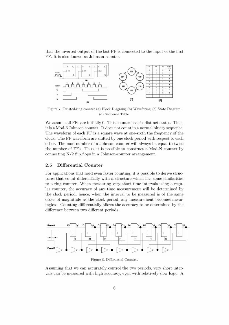
that the inverted output of the last FF is connected to the input of the firstFF. It is also known as Johnson counter.
Figure 7. Twisted-ring counter (a) Block Diagram; (b) Waveforms; (c) State Diagram;
(d) Sequence Table.
We assume all FFs are initially 0. This counter has six distinct states. Thus,it is a Mod-6 Johnson counter. It does not count in a normal binary sequence.The waveform of each FF is a square wave at one-sixth the frequency of theclock. The FF waveform are shifted by one clock period with respect to eachother. The mod number of a Johnson counter will always be equal to twicethe number of FFs. Thus, it is possible to construct a Mod-N counter byconnecting N/2 flip flops in a Johnson-counter arrangement.
2.5 Differential Counter
For applications that need even faster counting, it is possible to derive struc-tures that count differentially with a structure which has some similaritiesto a ring counter. When measuring very short time intervals using a regu-lar counter, the accuracy of any time measurement will be determined bythe clock period, hence, when the interval to be measured is of the sameorder of magnitude as the clock period, any measurement becomes mean-ingless. Counting differentially allows the accuracy to be determined by thedifference between two different periods.
Figure 8. Differential Counter.
Assuming that we can accurately control the two periods, very short inter-vals can be measured with high accuracy, even with relatively slow logic. A
6

differential counter is shown in Figure 10, has two periods which are com-binational delays, the faster one through a buffer, the slower one througha transparent latch. The idea is to measure the short interval between twoevents (signal edges) by propagating the first coming signal through theslower path (transparent latches) and the second one through the fasterpath (buffers). Since the path for the second signal is faster, there will bea moment when it will catch up the first signal, and the circuit in Figure10 captures that moment into a one-hot representation. If the two delaysare denoted as δ1 and δ2 and the second signal catches up after k stages,then the time interval between the two events is ∆ = k · (δ1− δ2) and it canbe seen that very small intervals can indeed be measured accurately if thedifference (δ1 − δ2) can be made small enough.
3 Counters Classification
There are many variations possible on the basic counter behavior by com-bining the basic counter behavior in order to obtain a more complex counterbehavior, hence it is useful to classify counters. The following list is notcomplete but have the most commonly found cases. Depending on whetherthe counter can be initialized to one state or to any state counters can beclassified as:
• Noninitializable — This is the simplest case, it can only be used forspecific applications (e.g., frequency divider).
• Resettable — This is necessary for most applications and also neces-sary for testing purposes, without a large penalty in performance orarea.
• Loadable — This is a more general case but typically has lower per-formance and higher complexity.
Depending on whether the counter traverses the circular state diagramin one direction only or in both, counters can be classified as:
• Up-only — This is the most common case and easy to understand.Counter counts in forward direction.
• Down-only — This is equivalent to the up-only case but it counts inbackward direction. In simple words it is opposite of the up-counter.
• Up/down — This is the most versatile but typically at the cost oflower performance. Depending upon the signal activated the countercounts in forward direction or in backward direction. Because of thisproperty it is sometimes called a “reversible” counter.
7

Depending on whether all the state registers are clocked with the samesignal counters can be:
• Asynchronous — Simple structure, cannot be read “on-the- fly,” canhave registers that are clocked by other signals than the clock. Likein the ripple-carry counter, the first flip-flop is clocked by the externalclock pulse, and then each successive flip-flop is clocked by the Q orQ’ output of the previous flip-flop.
• Semisynchronous — A “hybrid” attempt of combining the simplicityof asynchronous designs with a synchronous behavior on only some ofthe outputs.
• Synchronous — This is the most robust and can be read “on-the-fly”,but the routing and loading of the clock can become a performancebottleneck. In synchronous counter all memory elements are simulta-neously triggered by the same clock.
Sometimes it is possible to use “counters”with a state diagram that doesnot return from the last state to the initial state. Depending on whetherthis happens or not, counters can be classified as:
• Periodic — This is the normal case with a circular state diagram.
• Aperiodic — This is the case where the counter does not return to theinitial state (e.g., the differential counter).
Periodic counters can be classified according to the number of states:
• Modulo-2N — Special case of 2N states, typical for an N-bit binarycounter, the counter “wraps-around” from the last state by itself.
• Modulo-P — This is more general case than the modulo-2N , the modulo-P counter is many times obtained from a modulo-2N counter, eitherby decoding the state P and resetting to zero, or by loading with Pwhen the counter reaches zero. Modulo-P ring counters are obtainedwithout a need to decode states or explicitly load the counter.
Depending on the state encoding, counters can be classified as:
• Binary — The most common case in which the sequence of states isthe ascending or descending binary sequence.
• Quasi-binary — The case where the relation between a state and itsbinary equivalent can be easily determined.
• Non-binary ¯ The state encoding is not related to the binary se-quence(e.g., ring counters).
8

4 Prescaled Counters
The Prescaled counters, on which the paper is based, are synchronous cir-cuits having the following characteristics:1. Binary counting sequence.2. Clock period independent of counter size.3. Readable on the fly with the sampling rate being equal to the countingrate.4. Space complexity linear in the number of bits (i.e., O(N)).5. Count up, down, or up/down.6. Resettable.
The idea behind prescaled counter is the characteristic of the binarynumber system. The higher order bits are stable for long periods of timeand the terminal count (TC) output from the two least significant bits, whichbecomes a CARRY-in into the most significant block, is periodic with a lowerfrequency than the clock signal. For an M-bit counter block, the terminalcount will have a frequency 2M lower than the clock, with the moment whenthe terminal count from low-order bits is active being exactly the time whenhigher order bits need to be incremented. This means that the “virtual”frequency at which high-order bits need to operate is much lower than forthe low order bits.
Therefore, Prescaling long counters requires partitioning them into a se-ries of sub-blocks of increasing sizes in order to take advantage of the reducedfrequency required by high order bits. The simplest prescaled counters haveonly two such blocks, with a small and fast least-significant module calledthe prescaler and a slower large counter for high-order bits as shown inFigure 9.
Figure 9. Counter partition into a fast prescaler and a slower high-order partition.
For higher order blocks, successive terminal count signals from the pre-vious stages become exponentially farther apart in time, hence, higher orderblocks can have exponentially increasing sizes. In a correctly designed con-stant time counter, the clock period is limited only by the speed of the leastsignificant block, hence, the first prescaler is typically very small (one ortwo bits). The size of each sub-block must be chosen such that the CARRYpropagation inside the block is shorter than the delay between two succes-sive terminal counts from the corresponding prescaler. Thus, the CARRY
9

propagation inside the block is not on the critical path and does not affectthe clock period.
4.1 Terminal Count Generation
The prescaled generation of the TC-in to a partition has to be synchronouswith the true clock. Several different approaches have been proposed for theprescaled generation of the TC to high-order partitions. The first proposedsolution, by Ercegovac and Lang, uses a relatively inefficient ring/twisted-tail counter, which practically doubles the overall complexity of the counter.The ring/twisted-tail counters are regular and their VLSI implementationmay not be very inefficient. A much simpler TC generation, proposed byVuillemin, uses a backward CARRY propagation chain that takes the char-acteristics of the binary number system further into account.
4.2 Partitioning
Partitioning is the most important part of prescale counters. Depending onthe choice of the prescaled CARRY-in generation method, the partition sizescan be determined:1. In a top-down manner, first determine the size of the most significantblock, which is chosen as large as possible, and then recursively determinethe sizes of the lower order blocks. By assuming unit delays for the combi-national gates and a unit delay clock, an N-bit counter is first partitionedinto an (N - dlog2Ne) most significant block and into another dlog2Ne blockwhich is recursively partitioned in the same manner. For example, in thecase of a 64-bit counter, a top-down partitioning results in the followingblock sizes: 58, 3, 2, 1. The top-down procedure reduces the penalty paidfor having ring counter prescalers, but has the disadvantage that countersof different sizes will require different partition sizes, hence, design reuse isdifficult to implement. For a 128-bit counter, the top-down partioning leadsto: 121, 4, 2, 1 block sizes.2. In a bottom-up manner, first decide the size of the least significant block,then choose the second block as large as possible without affecting the clockperiod, then choose the third, etc. A bottom-up partitioning, assumes unitdelays for the combinational gates, and a unit delay clock. It determines theleast significant block with n0 = 1 bit, the second block with n1 = 2n0 = 2bits, the third block with n2 = 2(n0+n1) = 8 bits, and so on. For the sameexample of a 64-bit counter, a bottom-up partitioning results in the follow-ing block sizes: 53, 8, 2, 1. This bottom-up procedure has the advantageof using a few “standard size” modules as building blocks for counters ofdifferent lengths with only the most significant block of a non-standard size.For a 128-bit counter, the bottom-up partitioning leads to: 117, 8, 2, 1 blocksizes.
10

5 Constant-Time Up/Down Counters
The main advantage of up/down counters is that it have only a constantnumber of inputs (CLK, UP/DOWN, RESET, and CNT) independent ofthe counter size, hence, it seems more likely to be able to design a constanttime up/down counter. The main idea behind the technique for designingconstant time up/down counters is to realize that it is easy to have a con-figurable counter (configured as an up-counter, it will have a CARRY chainand, configured as a down-counter, it will have a BORROW chain) and theonly extra difficulty is when an up-only or down-only counter changes di-rection. This change of direction is the only moment when the CARRY (orBORROW) chain inside a block may not have enough time to propagateuntil the next TC from the corresponding prescaler. The solution proposedin the paper is to have the desired value prestored and simply load this valuewhen necessary, instead of trying to compute it. This can be easily accom-plished by using a shadow register that is always loaded with the previousblock value whenever the block is loaded with a new value.
Figure 10. Block diagram of the constant time up/down counter.
The block diagram of the proposed up/down constant time counter isshown in Figure 10. The design is synchronous, with a CLK active on therising edge, a RESET active HI, and an UP/DOWN input, which is LO forcounting up and HI for counting down. The following issues have determinedthe structure of the new counter:1. The prescaled TC generation must itself be up/down, hence it can beimplemented as an up/down ring counter and the top-down partitioningmethod is needed in order to minimize the size of the ring counters.2. Each block needs to be configurable for counting either up or down. Aseparate configuration bit for each block is needed to keep track of the blockconfiguration.3. Each sub-block has a shadow register that stores the previous blockvalue (i.e., decremented or incremented by one block-least-significant bit
11

depending on the configuration). When the block configuration is “up”,the shadow register stores the present value minus one LSB and when theconfiguration is “down”, it stores the present value plus one LSB.
The sub-blocks in this design function is practically independent of eachother, the ring counter inside each block effectively replace the need forreceiving the TC from lower order blocks. The complexity of the up/downcounter is more than up-only counter because of the extra shadow registerand the configurable CARRY chain.
5.1 Least-Significant Bit Counter
A 1-bit counter counts in the same sequence, no matter if it is up-only,down-only, or up/down, hence, the first block as shown in Figure 11, canbe a simple 1-bit counter which acts both as the 1-bit least significant bitand as a ring counter for the second block. There is no need for a shadowregister or configuration bit for the first block.
Figure 11. Least-significant bit block.
5.2 Configuration Bit
A configuration bit for each higher-order block keeps track of how the block isconfigured (up or down). A CARRY-in can occur only if the UP/DOWN in-put signal is 0 (UP), while a BORROW-in can occur only if the UP/DOWNinput signal is 1 (DOWN). There are four possible cases:Case 1. The block is configured “up” and a CARRY-in comes from the ringcounter. The configuration remains the same (up) and the block behaves likea normal up-only constant time counter. The shadow register gets loadedwith the present block value, while the block gets loaded with its next (in-cremented) value. Since the present configuration is “up”, this means thatthe previous “event” was also a CARRY-in, hence, enough time has passedfor CARRY propagation inside the Incrementer/Decrementer (which is con-figured as an incrementer).Case 2. The block is configured“down”and a BORROW-in comes from thering counter. The configuration remains the same (down) and the block be-haves like a normal down-only constant time counter. The shadow registergets loaded with the present block value, while the block gets loaded withits next (decremented) value. Since the present configuration is “down”, thismeans that the previous“event”was also a BORROW-in, hence, enough timehas passed for BORROW propagation inside the Incrementer/Decrementer
12

(which is configured as an decrementer).Case 3. The block is configured “up” and a BORROW-in comes from thering counter. The block changes configuration to “down” and it swaps thepresent value with the shadow register. The Incrementer/Decrementer out-put is disabled in this case, hence, there is no need in this case to wait forBORROW propagation.Case 4. The block is configured “down” and a CARRY-in comes from thering counter. The block changes configuration to “up” and it swaps thepresent value with the shadow register. The Incrementer/Decrementer out-put is disabled in this case hence, there is no need in this case to wait forCARRY propagation.
Figure 12. Configuration bit inside each block.
When after counting up for a number of cycles, the counter changesdirection by only changing lower order bits. In such a case, the high-orderblocks will still remain configured up and will only change configurationwhen a BORROW-in comes from the again, before a BORROW-in, thehigher order block will never know that the lower order blocks were in adifferent configuration for a period of time. The configuration register isimplemented as a simple D edge-triggered flip-flop as shown in Figure 12.The configuration of each block can only change when a CARRY-in (orBORROW-in) is received from the ring counter. When the configurationchanges (the present configuration is up and the next one is down, or vice-versa), the SWAP signal becomes active, which enables swapping the valueof the block with the shadow register. When the configuration stays thesame, the block register is loaded from the Incrementer/Decrementer andthe shadow register is updated with the previous block value.
5.3 Clock Period
For simplicity, unit delays are assumed for all the combinational gates inthe circuit (including multiplexes and XOR gates). There are several criti-cal paths in the circuit that determine the minimum clock cycle to be largerthan one unit delay, as in the case of the up-only counter:1. The least significant bit block has a unit delay, so it does not representthe critical path.2. Incrementing/decrementing the ring counter requires two unit delays,since the ring counter is a bidirectional shift register.3. Swapping the value of the block with the value of the shadow register
13
requires a unit delay through a multiplexer and in parallel, the multiplexercontrol signal requires two unit delays as shown in Figure 10. The timingof the UP/DOWN signal is on the critical path and the signal needs to besynchronized with the clock.4. By choosing a proper size for each block, the delay of Incrementer/Decrementerwhich takes care of CARRY (or BORROW) propagation inside the blockcan be masked, and this delay should not be on the critical path.
The clock frequency is independent of counter size but is lower (by a con-stant) than for an up-only counter because of the extra complexity. Insteadof being limited only by the low order prescaler, the speed is also limited bythe extra logic needed for swapping with the shadow register.
5.4 Up/Down Ring Counter
As explained in section 2.4, a 2N -bit twisted-tail ring counter has 2(N+1)
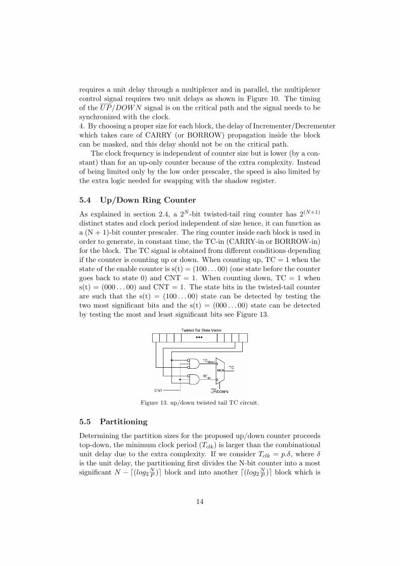
distinct states and clock period independent of size hence, it can function asa (N + 1)-bit counter prescaler. The ring counter inside each block is used inorder to generate, in constant time, the TC-in (CARRY-in or BORROW-in)for the block. The TC signal is obtained from different conditions dependingif the counter is counting up or down. When counting up, TC = 1 when thestate of the enable counter is s(t) = (100 . . . 00) (one state before the countergoes back to state 0) and CNT = 1. When counting down, TC = 1 whens(t) = (000 . . . 00) and CNT = 1. The state bits in the twisted-tail counterare such that the s(t) = (100 . . . 00) state can be detected by testing thetwo most significant bits and the s(t) = (000 . . . 00) state can be detectedby testing the most and least significant bits see Figure 13.
Figure 13. up/down twisted tail TC circuit.
5.5 Partitioning
Determining the partition sizes for the proposed up/down counter proceedstop-down, the minimum clock period (Tclk) is larger than the combinationalunit delay due to the extra complexity. If we consider Tclk = p.δ, where δis the unit delay, the partitioning first divides the N-bit counter into a mostsignificant N − d(log2
NP )e block and into another d(log2
NP )e block which is
14

recursively divided in the same manner until the smaller block is a 1-bitcounter. For p = 2 and N = 64, the partitioning leads to the sizes:60,3,1.
5.6 Incrementer/Decrementer
The Incrementer/Decrementer can be easily implemented as a ripple chain,as shown in Figure 14. For an n-bit block, the delay through the ripple chainwill be n times the unit logic delay and if this delay is less than the time be-tween two consecutive CARRY-ins (or BORROW-ins) from the ring counter(which should always be true by partitioning), the Incrementer/Decrementeris not on the critical path. The configuration is controlled by the configura-tion bit for each block.
Figure 14. Incrementer/Decrementer.
5.7 Initializing the Counter
For a regular N-bit counter which has 2N possible states, all the states arelegal. In the case of the proposed constant time up/down counter, whichhas many extra state flip-flops (the configuration bits, the ring counters, theshadow registers), it is very important to initialize the counter to a legalstate. A RESET signal is needed to initialize all the configuration bits to 0(counting up), the counter block values to all-zeros, the shadow registers toall-ones (block value minus 1), and the ring counters to all-zeros.
6 Alternative Design - use of Carry/Borrow Reg-ister
An alternative solution to the use of a shadow register is to store the bit-wiseXOR between the previous state and the current state in the Carry/BorrowRegister (CBReg). With this information available, it is possible to restorethe desired previous state in one gate delay. For comparison, both solutionsare presented in Figure 15. In Figure 15(a), the carry bit that was used inthe last transition is stored in CBReg and is used in the place of the carrycomputed by the incrementer/decrementer chain. Figure 1(b), the value ofthe previous state is stored in a shadow register and can replace the nextstate that is being computed by the incrementer/decrementer.
15

Figure 15. Design of next state generator (a) Using carry/borrow from previous state
transition; (b) using shadow register to store the previous state bit.
7 Conclusion
The methodology behind designing synchronous up/douwn counters of ar-bitrary length with period independent of counter size is presented in detail.The main idea of the solution to the problem is to store the previous stateof the counter for use when the counter reverses direction. For that useof two type of registers is described. Use of Shadow Register is explainedin detail and simple procedure of the use ofCarry/Borrow Register is de-scribed. The experimental results for the up/down counters were obtainedusing simulation for a 64-bit design and estimates of the area and delays forother cases.
The paper is very technical and very well explained. To make the basic,simple counter and examples are given. Counter classification is very helpfulin understanding the characteristic of the counters. Block diagrams of eachcounter and their parts helped in understanding the working of countersmore easily.
References1: Digital Systems Principles and Application By Ronald J. Tocci.2: Computer Arithmetic Algorithms and Hardware Designs By BehroozParhami3: http://www.play-hookey.com/digital/synchronous counter.html4: http://www.eelab.usyd.edu.au/digital tutorial/part2/counter01.html5: http://www.hcc.hawaii.edu/∼ richardi/113/index.htm
16