1.1 current status of the iron and steelmaking industry
TRANSCRIPT

Reduction of iron ore fines in the ffcon furnace 1
1 Introduction
1.1 Current status of the iron and steelmaking industry
Current world iron production comprises of 600 million tons per year (MTPY) of hot
metal and pig iron, 37.1 MTPY of direct reduced iron (DRI) and hot briquetted iron
(HBI), and approximately 2 MTPY of hot metal produced by direct smelting. Most hot
metal is produced in blast furnaces, which are operated in conjunction with mining
beneficiation plants, pelletizing plants, sinter plants, coke batteries, limestone plants,
oxygen plants, fuel gas plants and power stations(l).
Virtually all the steel in the world is either produced in an oxygen steelmaking
converter (such as a BOF, LD or OBM (Q-BOP)) or an electric arc furnace (EAF)(2).
Most of these steelmaking equipment was built or rebuilt between 1955 and 1975.
The BOF and EAF were the best technologies available at that time to further process
blast furnace hot metal and relatively inexpensive scrap, into steel.
During the last three decades, more efficient blast furnaces, oxygen steelmaking,
continuous casting and hot metal- and ladle metallurgy practices were developed.
However, technology drivers are currently changing. At present, the most important
technology drivers are(2,3,4) :
~ Lower capital and fixed cost: The capital cost to value added ratio for
integrated steelmaking is the highest of any major industry. Existing facilities
are therefore expanded and renewed to optimise their useable life(l). Both
ore-based production and scrap-based production are accompanied by high
fixed, labour and raw material cost. Producers therefore tend towards lower
capital costs as well as lower and more flexible fixed costs.
~ Energy and environmental: Environmental drivers are usually in response
to national or international regulation, with reduction of greenhouse gasses
and recycling of steelmaking waste materials the major drivers. The
reduction of energy consumption goes hand in hand with reduction of CO2
emissions. Although reduction of energy consumption may be limited (due to
the laws of conservation of energy), CO2 emissions can be reduced by using
fossil fuels to replace electrical energy. Note that electrical energy is only
about 30-40% effective when considering production and transmission.
1
Reduction of iron are fines in the ffcon furnace 2
~ Flexibility: In order to be responsive to market conditions, steel makers need
flexibility regarding raw materials, energy and production. Flexibility
regarding the use of scrap, hot metal, direct reduced iron (DRI), waste oxides
and iron carbide, and the substitution of coke with coal(S), will allow the
producer to minimize input costs. The use of fossil fuel as well as electrical
energy will optimise the process with respect to energy, cost and productivity.
Finally, processes that can reduce or increase production economically will
enable producers to respond to market conditions.
~ Competitive forces: New technologies need to be competitive with existing
technologies. The production cost of liquid steel therefore needs to be
reduced continuously.
Industry's response to these technology drivers will probably result in incremental
improvements in existing technologies as well as in major dev.elopments in certain
areas (of which one is direct iron and steelmaking processes)(6). During the next 20
years the blast furnace will continue to produce .most of the iron requirements, while
direct reduced iron (DRI) could represent 20% of the virgin iron units by 2015(3).
Direct smelting may be commercialised, initially for treatment of waste oxides and to
supplement scrap or to increase hot metal in integrated plants(6).
1.2 Direct reduction processes
Direct reduction processes are methods for reducing iron ore directly to metallic
iron(7). These methods bypass several of the steps currently used in conventional
steelmaking. Direct reduction processes can be separated into two major categories:
i.e. gas-based- and coal-based processes.
1.2.1 Gas-based DRI processes
Gas-based processes dominate the direct reduced iron (DRI) market, with shaft
furnace gas-based processes accounting for 94% of world DRI production. From
this, the Midrex process accounts for 70% (with 50 operational furnaces), the HYL
processes accounts for 23% (with 29 operational furnaces) while the Arex accounts
for approximately 1% (with 5 operational furnaces). The contribution of the Purofer
furnace is negligible(!) while the Danarex process is still at pilot plant stage. The
major differences between these processes are the way in which reducing gas for the
2

Reduction of iron ore fines in the ffcon furnace 3
process is generated, The Midrex uses a natural gas reformer, the HYL uses a steam
reformer, and the Arex is based on direct injection of natural gas into a reduction
shaft , All of these processes require the use of high grade, sized iron ore lumps
and/ or pellets as feedstock, Typical process parameters for shaft furnace gas-based
processes are shown in Table 1 .
Table 1 : Process parameters for shaft furnace gas-based processes ( 1,8) ,
Parameter 1""' li "'dMX r Hn Hn II 1 ~I p~:::::) ref~:::~g) d~'
II~ "":o~r""'e/~p""'e~lIe""'ts~)'i-o: t~/""'t ~DR~I 1-1.45 . 1.45 I 1.42 I I 1.45 II 1.42 II
I Natural gas If Gcal/t I 2.42 jr 2.42 :Ji 2,23 . 12.2-2.4]C.4 ]1 Oxygen
, NmJ/t
Pressure atm 1
1~C: .. M":e",t":a"""lI",,iz .. a:,,t~i o~n~II~,,""":,olo~O ~~I!l 92 -9 5
I %C in DRI 1[ % Ji 1.0-3.5 J[ [CaPital cost )l USD/t Jf 125 II
-=:JI 41 Ji II 38 II
5 JI II 2 II 1 II
92-95
1.2-4.5 I[ 92-95 I 92-95 II 91-94]
1.0-5.0 J 1 ,8-2.0 r1.0~?J1 140 ]I JI II
In addition to shaft furnace gas based processes are flu id ised bed gas based
technolog ies such as the Fior-, Finmet- , Iron carbide- and Circored processes,
These processes were developed to use iron ore fines as feedstock and are mostly
mUlt i-stage processes,
The Finmet process was derived from the Fior process (of which a plant is
operational in Venezuela ), Two Finmet plants are currently operational: one at Port
Hedland , which was commissioned in 1999, and another that was commiss ioned at
Orinoco Iron C.A in 2000, The Finmet is a 4-stage process, operating at a pressure
between 11 and 13 atm, and temperatures between 550°C and 800°C. The main
problems encountered wi th th is process were difficulties in achieving high degrees of
reduction due to temperature control as well as problems with briquetting of the
product.
3
Reduction of iron are fines in the ffcon furnace 4
The Iron carbide process, which was developed by Hazen Research Institute, uses
iron ore fines to produce 80% Fe3C. The single vessel process is essentially a two
stage batch process . During the first stage the ore is reduced at temperatures
between 570°C and 600°C with hydrogen (from a steam reformer) , after which the
metal is carburised with methane. Although the design capacity of the plant was
300000 tons per annum (tpa), the Trinidad plant had an actual capacity of 120000
tpa and was therefore shut down in 1999.
The Circored process, which was developed by Lurgi and commissioned in 1999,
produces HBI from iron ore fines. For this, the process uses almost pure hydrogen,
which is produced in a steam reformer with natural gas as heat source. The process
comprises of two reduction stages, i.e. a circulating Fluid ized bed as well as a fixed
fluidised bed. The Fluidized bed operates at 630°C and a pressure of 4 atm to
achieve between 92 and 93% metallisation. Due to the use of hydrogen as reductant
the carbon content of the product is virtually zero . Although the process uses readily
available ore fines, the operating cost of the process is relatively high.
1.2.2 Coal-based DRI processes
Coal-based DRI processes comprise the following:
~ Rotary kiln based processes
~ Rotary hearth based processes
~ Fluidised bed based processes
The coal-based processes are less environmentally friendly than gas-based
processes, due to higher CO, emissions. The production of fine ashes containing
sulfur compounds, which requires treatment before disposal, is another potential
problem of these processes(!)
Coal based DRI production is mainly accounted for by rotary kiln processes such as
the SL/ RN process (with commercial plants in South Africa, India and New Zealand ),
the Davy process (with commercial plants in South Africa and China ), and the Accar
process (with a commercial plant in Norway) .
4

Reduction of iron ore fines in the ffcon furnace 5
The SL/RN process is schematically shown in Figure 1
Figure 1 :
(_ECT,"~-ST":"-I:
r '1 r:.AT;'-:)R
I :':-E'O W.\T£R
) RJTARY C-::L(P
r-
Schematic illustration of the SL/RN process(1)
Rotary kilns (such as the SL/ RN) typically have capacities ranging between 150000
and 200000 tpa. These processes charges lump ore, pellets and fines (1.42 t/t HB!),
fine coal (0.85 t/t HBI) and limestone and dolomite (mainly for sulphur removal) into
an inclined kiln that rotates at speeds less than 1rpm. The ore is dried, pre-heated
and reduced as it moves along the length of the kiln. Between 92 and 93 %
metallization of the iron ore is achieved within 14 hours, due to solid state reduction
in the composite bed. The heat for reactions is provided by combustion of coal and
part of the CO and H, that evolves from the reduction reactions, as well as from air
fuel burners. The process is operated at atmospheric pressure in the temperature
range 10000C to 1100°C. At the discharge end DR! is separated from char and ash to
yield metal with a carbon content of 0.5% and sulphur content less than 0.02% . The
major weaknesses of the process are the high capital cost, limited plant size, possible
environmental impact, complex handling procedures at the exit end of the kiln and
quality limitations of the DR! due to the presence of sulphur and gangue.

Reduction of iron ore fines in the ffcon furnace 6
Rotary hearth coal-based processes include the Fastmet, Inmetco, Comet,
Primus, 101, Redsmelt and Itmk3 processes. The Fastmet process is schematically
shown in Figure 2.
Figure 2:
Burner ,,-"---... Fuel ~mJlJrJ,{
Hot Reduced Pellets
Solids Flow
Schematic illustration of Midrex's Fastmet process(l).
In the Fastmet and Inmetco processes, pellets containing ore fines (1.34 tit DRI) and
coal fines (0.38 tit DRI) are charged onto a rotary hearth where they are dried, pre
heated and reduced in the solid state. Carbon in the agglomerate is the reductant,
with various air-fuel burners providing heat for the reactions. The process is
operated at atmospheric pressure in the 12000C to 1350°C range. 92% Metallization
is achieved within 12 to 15 minutes to produce metal with a carbon content between
1.5 and 5%, and sulphur content between 0.12 and 0.2%. The design capacity
regarding iron production is 450000 tpa. However, the two operational plants that
were commissioned in 2001 at Kobe steel (for processing of waste oxides) have
capacities of 50000 tpa.
The Comet process is similar to the Fastmet and Inmetco processes, but ore and coal
fines are charged as discrete layers. Since the excess char and ash can be removed
from the final product, the DRI produced has lower carbon (0.5 to 0.7%) and sulphur
(0 .02 to 0.06%) content.
The fluidising bed coal-based Circofer process (developed by Lurgi) is similar to
the Circored process. The difference however is that instead of using natural gas,
the process uses gas generated (at 1000°C in a gasifier) from coal. The main inputs
6

Reduction of iron ore fines in the Ifcon furnace 7
to the process consist of iron ore fines (1.42 tit HBI), coal (0.8 tit HBI) and oxygen
(205 Nm3/t HBI). The iron ore fines (in the size range 0.03 to 1.00 mm) are pre
heated to between 800 and 900°C and pre-reduced during the first stage in a
circulating fluidised bed, after which final reduction occurs in another fluidised bed.
The process produces 92 % metallized HBI with carbon content about 2% and
sulphur content less than 0.02%. The design capacity for this plant is 500000 tpa.
1.3 Direct Smelting processes
1.3.1 Two stage processes
Two stage direct smelting processes are processes such as the Corex, Finex, Hismelt,
AISI, OIOS, CCF (which is similar to cleansmelt), IDI, Redsmelt, Fastmelt, Inmetco
etc. These processes use an ore pre-reduction step followed by a smelting step.
Pre-reduction occurs either in shaft furnaces (Corex and AISI), fluidised beds (DIOS
and Hismelt), rotary hearth furnaces (Redsmelt) or melting cyclones (CCF). In these
processes, ore is charged to the pre-reduction furnace where off gas from the smelter
unit is used for partial reduction of the ore. The partially reduced ore, coal, fluxes,
oxygen and/or air are fed to the smelter unit, containing hot metal and slag. The
furnace is operated at a pressure of 4 atm with the temperature of the pre-reduction
shaft and smelter approximately 900°C and 15000 C respectively. Since the cleaned
product gas from these processes has considerable value, the gas is either consumed
as fuel for the plant, utilised in direct reduction plants, or used to produce electricity.
The Corex process (developed by Voest Alpine) is schematically shown in Figure 3.
This is the only smelting reduction technology in commercial use, with four of the
five plants currently operational.
7

Figure 3:
Reduct ion of iron ore fines in the Ifcon furnace 8
M~I1" r G~qifie r
Hot MetAl And Slag
Pell,ts/Addltlves
Top Gss
Reduction Shaft
...
Reduction Gas
Ol:ygen
Scrubber
Hot Ga. Cyclon~
Gas
Schematic illustration of the Corex process(!) .
Export Gas
Settling Pond
Typical consumption rates for the Corex are as follows: lump ore and pellets: 1.48 ti t
hot metal (HM), coal : 0.98 ti t HM (of which 10% is usually coke) and limestone:
0.242 t i t HM . The carbon content of the metal produced is typically 4 to 5% and the
sulphur content between 0.05 and 0.1 % . The slag typically has a CaO/ Si02 ratio
between 1 and 1.3, with a FeO content between 1 and 2. Typical production rates
are between 600000tpa and 1.1 MTPY. The major weaknesses of the process are
high capital cost, limited size compared to blast furnaces and the need to utilize off
gas to be competitive.
1.3.2 One stage processes
One stage direct smelting processes are processes such as the Romelt (also
Vanyukov), Technored, Ausmelt and Ifcon® The Romelt process is schematically
shown in Figure 4.
8

Reduction of iron are fines in the ffcon furnace 9
C:f:=:~.:'.,,~, °xx~en \8
1- foaming slag; 2- siphon for hot metal; 3- siphon for slag; 4 - refractory lined hearth; 5 - orifice; 6 - feed hopper; 7 - flue gas duct; 8 -lower tuyeres;
9 - upper tuyeres; 10 - calm slag; 11 - water-cooled panels
Figure 4: Schematic illustration of the Romelt process(1).
In Romelt and Ausmelt processes, lump or fine ore, coal and fluxes are charged
directly into the smelter containing hot metal and slag. The Romelt process uses
tuyeres located in the vessel sidewalls for air/oxygen injection, while the Ausmelt
(which was developed for non ferrous metals) uses a top lance system. Fine coal is
also injected through the lance in the Ausmelt process.
The Romelt process consumes 1.5 to 2.0 tons of iron ore fines, 0.8 to 1.1 tons of
coal, 0.1 tons of limestone, 850 to 1100 Nm3 of oxygen and 450 to 700 Nm3 of air to
produce a ton of hot metal. The hot metal contains 4 to 5 % carbon and 0.025 to
0.05 % sulphur, while the slag produced has a CaO/Si02 ratio between 1 and 1.3,
with a FeO content between 1.5% and 3%.
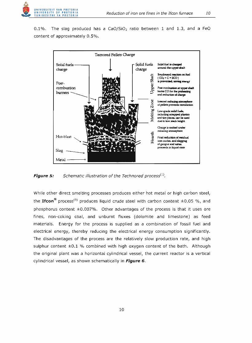
The Technored process (which is shown schematically in Figure 5) uses unfired
green pellets (1.5 to 1.6 tit HM) and coal (0.74 tit HM) to produce hot metal with
carbon contents between 3.5% and 4.5%, and sulphur contents between 0.05% and
9
Reduction of iron ore fines in the Ifcon furnace 10
0.1%. The slag produced has a CaOjSi02 ratio between 1 and 1.3, and a FeO
content of approximately 0.5%.
Figure 5:
Solid fuels ---, charge
Postcombustion burners _____
Hot-blast ~
Metal -----+
Tecnored Pellets Charge
1 Solid fuels charge
Solid fuel is charpd uound the upper IhaIt
.:::: Boudouard radian on fuel ~ (CO,+C-XO) (J) is prevented. ..... BI8JY
~ I'ost combustion at uppw shaft ::> bums co trw !be preIwaIing
.net reduction 01 chup
:!! InIema1 reducinr aano.pbee ~ of peIIetI ~ noxidatian
~ Low~de.olid tuell, '.c including SCftpped plutia ~ Ind tin pieces. can be used
~ ..... __ ~ duelDlowslackheight
Final reduction of residUAl iron oxides, Ind sllgging of pngue .net ashes, proceeds in liquid s!alle
Schematic illustration of the Technored process(l),
While other direct smelting processes produces either hot metal or high carbon steel,
the Ifcon® process(9) produces liquid crude steel with carbon content ±O.OS %, and
phosphorus content ±0.007%. Other advantages of the process is that it uses ore
fines, non-coking coal, and unburnt fluxes (dolomite and limestone) as feed
materials. Energy for the process is supplied as a combination of fossil fuel and
electrical energy, thereby reducing the electrical energy consumption significantly.
The disadvantages of the process are the relatively slow production rate, and high
sulphur content ±0.1 % combined with high oxygen content of the bath. Although
the original plant was a horizontal cylindrical vessel, the current reactor is a vertical
cylindrical vessel, as shown schematically in Figure 6.
10

0 , / Air Lance
Slag
Slag tapping spout
Reduction of iron are fines in the ffcon furnace 11
Raw material
Feeders
Freeboard
Solids bed
Off gas
+--+--+ Outer surface of solids bed
Final reduction and melting
Meta l tapping spout
Induction heater
Figure 6: Schematic representation of the current configuration of the
Ifcon® furnace.
1.4 Process description of the Ifcon® process
The feed material is a composite mixture of iron ore fines, coal, dolomite and
limestone. The material mixture is fed from the top of the furnace, through the
freeboard , onto a solids bed . The solids bed, which floats on top of the metal bath ,
covers most of the planar surface of the bath.
The bath is heated from below with induction hea ters . Molten metal and slag are
tapped intermittently through tapping spouts, by tilting the vessel.
Combustib le gasses (such as CO and H2 ) {l O) are released into the freeboard, from the
so lids bed. Additional heat for the process is provided by post -combustion of these
gasses with oxygen enriched air.
The amounts of ore and coal fed into the furnace, is controlled in such a way that
there is always a slight excess of iron oxide in the slag. This means that the burden
11

Reduction of iron ore fines in the Ifcon furnace 12
at the bottom of bed is almost depleted of carbon. This resu lts in the production of
low carbon crude steel.
The Ifcon® process can be div ided into three characterist ic horizontal zones: the
freeboard , the so lids bed and the liquid bath, which are schematically shown in
Figure 7. The main material and energy flows are also indicated in the figure .
FEED MATERIALS 0" Coal Dolomite Umestone
\ .
FREEBOARD
SOLIDS BED
LlQUIOBATH
INDUCTION HEATING
FURNACE OFF-GAS
BLAST MIXTURE Oxygen Ai r
TA. liquid s teel Uquid slag
Figure 7: Schematic representation of the Ifcon process, indicating
the most significant mass and energy input and output streams.
1.4.1 The Freeboard
The main purpose of the freeboa rd is to generate heat by post-combustion of process
gasses and other combustibles. This is achieved wi th oxygen-enriched air.
The heat generated is transferred to the upper part of the so lids bed, where it is used
to drive the overall endothermic reduction reactions.
The rate at which heat is generated for a specific air oxygen mixture is mainly
determined by the rate at which combustible gasses evolve from the solids bed and
the degree of post-combustion achieved in the freeboa rd (1l,12.13>,
12
Reduction of iron are fines in the ffcon furnace 13
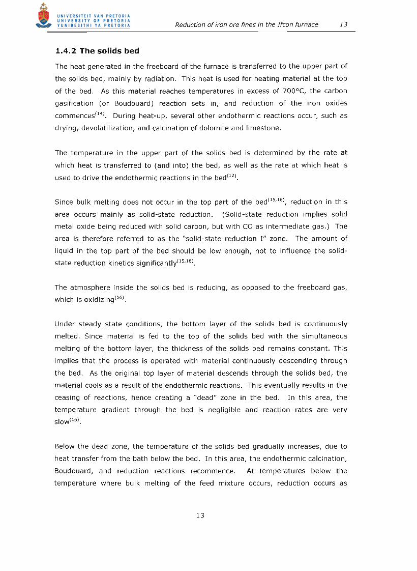
1.4.2 The solids bed
The heat generated in the freeboard of the furnace is transferred to the upper part of
the solids bed, mainly by radiation. This heat is used for heating material at the top
of the bed. As this material reaches temperatures in excess of 700°C, the carbon
gasification (or Boudouard) reaction sets in, and reduction of the iron oxides
commences(14). During heat-up, several other endothermic reactions occur, such as
drying, devolatilization, and calcination of dolomite and limestone.
The temperature in the upper part of the solids bed is determined by the rate at
which heat is transferred to (and into) the bed, as well as the rate at which heat is
used to drive the endothermic reactions in the bed(12).
Since bulk melting does not occur in the top part of the bed(15,16), reduction in this
area occurs mainly as solid-state reduction. (Solid-state reduction implies solid
metal oxide being reduced with solid carbon, but with CO as intermediate gas.) The
area is therefore referred to as the "solid-state reduction I" zone. The amount of
liquid in the top part of the bed should be low enough, not to influence the solid
state reduction kinetics significantly(15,16).
The atmosphere inside the solids bed is reducing, as opposed to the freeboard gas,
which is oxidizing(16).
Under steady state conditions, the bottom layer of the solids bed is continuously
melted. Since material is fed to the top of the solids bed with the simultaneous
melting of the bottom layer, the thickness of the solids bed remains constant. This
implies that the process is operated with material continuously descending through
the bed. As the original top layer of material descends through the solids bed, the
material cools as a result of the endothermic reactions. This eventually results in the
ceasing of reactions, hence creating a "dead" zone in the bed. In this area, the
temperature gradient through the bed is negligible and reaction rates are very
SIOW(16).
Below the dead zone, the temperature of the solids bed gradually increases, due to
heat transfer from the bath below the bed. In this area, the endothermic calcination,
Boudouard, and reduction reactions recommence. At temperatures below the
temperature where bulk melting of the feed mixture occurs, reduction occurs as
13

Reduction of iron are fines in the ffcon furnace 14
solid-state reduction. This area is therefore referred to as the "solid-state reduction
II" zone.
This study will investigate reduction occurring in the solids bed.
1.4.3 The molten bath
As the material at the bottom of the solids bed is heated to a temperature exceeding
the liquidus of the slag, bulk melting of the material (as well as dissolution of solids
into the slag) occurs. It is therefore expected that reduction, in this area, will occur
as liquid-solid-state reduction . (Liquid-solid-state reduction implies reduction of
molten metal oxide (which is dissolved in a slag) with carbon, which is either solid or
dissolved in the metal, with CO as intermediate gas.) The mixing reaction regarding
slag formation, as well as the reactions between metal and slag, is also expected to
occur in this zone(16). This is where final reduction and melting of bed material
occurs and is referred to as the "final reduction and melting" zone.
Electrical energy input to the bottom of the furnace is required to supply energy for
the reduction reactions occurring in the "solid-state reduction II" and "final reduction
and melting" zones. Electrical energy is also required for melting of the slag and
metal produced. The metal bath acts as a transport medium for this energy(13). The
bath also serves as a reservoir for the produced metal and slag.
The slag chemistry of the process is controlled by changing the feed mixture. Slag
metal equilibrium is however not achieved(17).
By considering the discussion above, the process can be re-divided into six zones, as
shown in Figure 8.
14

Reduction of iron are fines in the Ifcon furnace 15
FEED MATERIALS 0,. Coal Dolomite Limestone
1 FURNACE OFf -GAS
FREEBOARD 0
SOLID STATE REDUCTION I
DEAD ZONE
SOLID STATE REDUCTION /I
FINAL REDUCTION AND MEL TING
0
MOL TEN METAL
\ Y •
INDUCTION HEATING
BLAST MIXTURE Oxygen Air
TAP liqu id steel Liqu id slag
Figure 8: Schematic representation of the IFCON process, indicating the most
significant mass and energy input and output streams
1.5 Hypothesis statement
During the first Ifcon test work(18) 80% reduction was achieved in the upper part of
the solids bed, at a feed rate of 135 Fe/m'/h (which corresponds with a production
rate of 56 kg Fe/m' / h) . During pilot plant trails, crude steel was produced at a rate
of 100 kg Fe per m' (sca led to the planar surface area of the bath ) . Additional
investigations(10.12, 19) showed that approximately 30% reduction was achieved (as
solid state reduction ) in the "solid state reduction I n zone of the so lids bed. At the
time it was assumed that the rate of reduction was controlled by a combination of
the rate of heat transfer from the freeboard to the solids bed and the rate of the
gasification reaction. It was also assumed that volatiles did not contribute to the
reduction reaction in the solids bed(lS)
15

Reduction of iron ore fines in the ffcon furnace 16
Regarding the bottom of the solids bed, it was assumed that final reduction (up to
80% reduction ) was achieved as solid-state reduction. The reduced burden was then
melted, to form slag and liquid metal.
1.5.1 Objective of this study
This study aimed to test the assumptions stated above, by investigati ng the
following:
" Is the rate of reduction in the so lids bed influenced by the rate of heat
transfer to the solids bed?
" Is the rate of reduction in the solids bed influenced by the reactivity of the
coal ?
" Is the rate of reduct ion in the solids bed influenced by the reducib ility of the
ore?
" Does volatiles contribute to the rate of reduction in the sol ids bed?
" Is final reduction (up to 80% ) achieved as solid -state reduction at the bottom
of the solids bed, when produci ng at a rate of 100 kg Fe per m ' of planar bath
surface area, per hou r ?
" If final reduction is not achieved as so lid-state reduction, at a rate of 100 kg
Fe/ m'/h, what is the extent of reduction achieved as solid-state reduction?
Ifcon® is a very complex and integrated process, which cannot be dupl icated in a
single laboratory experiment. The investigation was therefore done in two phases.
1. 5 .1 .1 Phase 1: Rate determining step investigation
The main aim of the first phase of this investigation was to determine the optimum
feed materials (and criteria for the selection of optimum feed material ) for the "Solid
state Reduction In zone. From literature, it was not clear what the rate-determining
steps are during reduction in a solids bed (comprising of ore coal and fluxes ) . The
influence of changes to specific material characteristics and process parameters on
the extent of reduction achieved in a mixed solids bed was therefore determined
experimental ly .
16
Reduction of iron are fines in the ffcon furnace 17
Process parameters that were varied included:
~ Ore type (to achieve changes to the reduction rate constant).
~ Coal type (to achieve changes to the Boudouard rate constant).
~ The temperature to which the material mixture was exposed .
A modelling approach combined with experimental results was used to do the
investigation.
Note that the accent of this study was to confirm whether specific process
parameters influenced the rate of solid-state reduction of a composite material
mixture, and therefore results were more of a qualitative, than quantitative nature.
1.5.1.2 Phase 2: production rate investigation
The second phase of the investigation focussed on solid -state reduction at the
bottom of the solids bed. The main objective of this phase of the study was to
investigate the extent to which final reduction occured as solid-state reduction at the
bottom of the solids bed. Secondary objectives were to back calculate the heat
transfer coefficient in the solids bed and to determine the rate at which final
reduction can be achieved as solid-state reduction (in the solids bed of the Ifcon®
process). For this, a modelling approach combined with experimental results was
also used.
17