1/45 chapter 5 – signal encoding and modulation techniques
TRANSCRIPT
1/45
Chapter 5 – Signal Encoding and Chapter 5 – Signal Encoding and Modulation Techniques Modulation Techniques
2/45
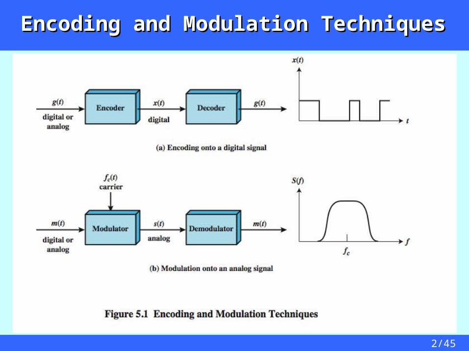
Encoding and Modulation TechniquesEncoding and Modulation Techniques
3/45
Digital Signaling Versus Analog Digital Signaling Versus Analog SignalingSignaling
Digital signaling Digital or analog data is encoded into a digital signal Encoding may be chosen to conserve bandwidth or to
minimize error
Analog Signaling Digital or analog data modulates analog carrier signal The frequency of the carrier fc is chosen to be compatible
with the transmission medium used Modulation: the amplitude, frequency or phase of the carrier
signal is varied in accordance with the modulating data signal by using different carrier frequencies, multiple data signals
(users) can share the same transmission medium
4/45
Digital SignalingDigital Signaling
Digital data, digital signalSimplest encoding scheme: assign one voltage level to binary
one and another voltage level to binary zeroMore complex encoding schemes: are used to improve
performance (reduce transmission bandwidth and minimize errors).
Examples are NRZ-L, NRZI, Manchester, etc.
Analog data, Digital signalAnalog data, such as voice and videoOften digitized to be able to use digital transmission facilityExample: Pulse Code Modulation (PCM), which involves
sampling the analog data periodically and quantizing the samples
5/45
Analog SignalingAnalog Signaling
Digital data, Analog SignalA modem converts digital data to an analog signal so that it
can be transmitted over an analog lineThe digital data modulates the amplitude, frequency, or
phase of a carrier analog signalExamples: Amplitude Shift Keying (ASK), Frequency Shift
Keying (FSK), Phase Shift Keying (PSK)
Analog data, Analog SignalAnalog data, such as voice and video modulate the
amplitude, frequency, or phase of a carrier signal to produce an analog signal in a different frequency band
Examples: Amplitude Modulation (AM), Frequency Modulation (FM), Phase Modulation (PM)

6/45
Digital Data, Digital SignalDigital Data, Digital Signal
Digital signaldiscrete, discontinuous voltage pulseseach pulse is a signal elementbinary data encoded into signal elements
Periodic signalsPeriodic signals
7/45
Data element: a single binary 1 or 0 Signal element: a voltage pulse of constant amplitude Unipolar: All signal elements have the same sign Polar: One logic state represented by positive voltage the other
by negative voltage Data rate: Rate of data (R) transmission in bits per second Duration or length of a bit: Time taken for transmitter to emit
the bit (Tb=1/R)
Modulation rate: Rate at which the signal level changes, measured in baud = signal elements per second. Depends on type of digital encoding used.
8/45
Interpreting SignalsInterpreting Signals
Need to know timing of bits: when they start and endsignal levels: high or low
factors affecting signal interpretationData rate: increase data rate increases Bit Error Rate (BER)Signal to Noise Ratio (SNR): increase SNR decrease BERBandwidth: increase bandwidth increase data rate encoding scheme: mapping from data bits to signal elements

9/45
Comparison of Encoding Schemes
signal spectrumLack of high frequencies reduces required bandwidth, lack of dc component allows ac coupling via transformer,
providing isolation, should concentrate power in the middle of the bandwidth
Clockingsynchronizing transmitter and receiver with a sync
mechanism based on suitable encoding
error detectionuseful if can be built in to signal encoding
signal interference and noise immunitycost and complexity: increases when increases data rate

10/45
Encoding Schemes
Positive level (+5V)
Negative level (-5V)
Positive level (+5V)No line signal (0V)Negative level (-5V)

11/45
Encoding Schemes
12/45
NonReturn to Zero-Level (NRZ-L)
Two different voltages for 0 and 1 bitsVoltage constant during bit interval
no transition, i.e. no return to zero voltagemore often, negative voltage for binary one
and positive voltage for binary zero
13/45
NonReturn to Zero INVERTED (NRZI)
Nonreturn to zero inverted on onesConstant voltage pulse for duration of bitData encoded as presence or absence of signal
transition at beginning of bit time transition (low to high or high to low) denotes binary 1no transition denotes binary 0
Example of differential encoding since have– data represented by changes rather than levels– more reliable detection of transition rather than level
14/45
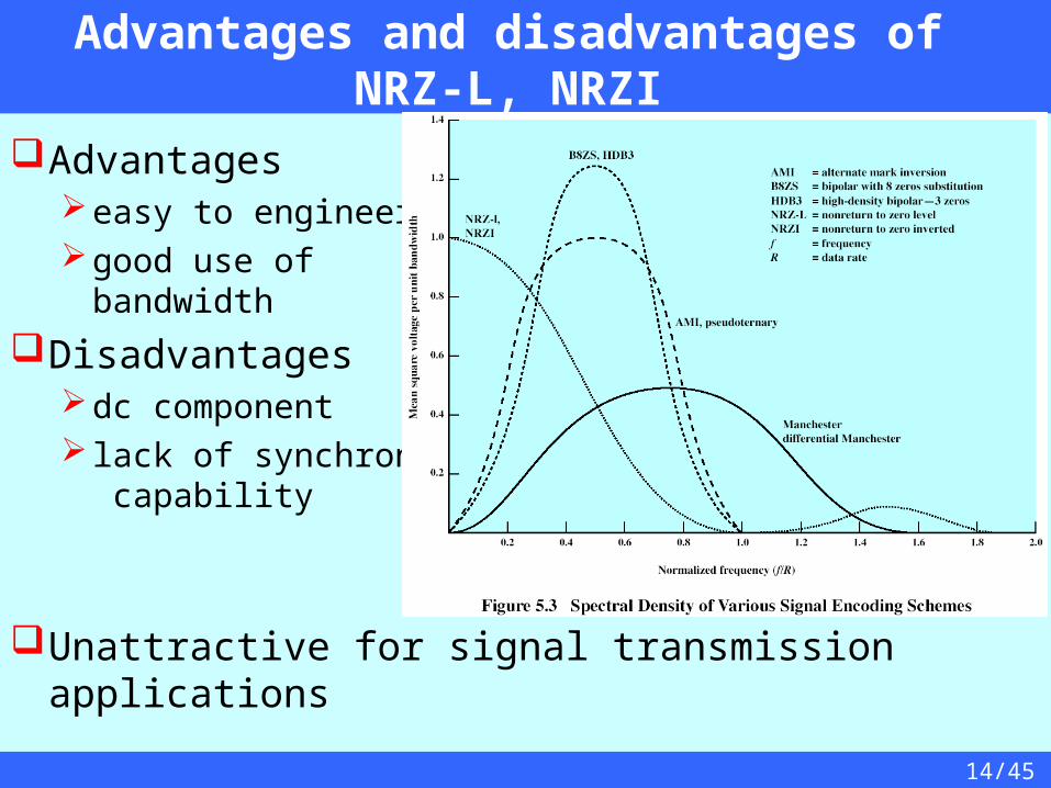
Advantages and disadvantages of NRZ-L, NRZI
Advantageseasy to engineergood use of
bandwidth
Disadvantagesdc component lack of synchronization
capability
Unattractive for signal transmission applications

15/45
Multilevel BinaryBipolar Alternate Mark Inversion (AMI)
Use more than two levels (three levels, positive, negative and no line signal)
Bipolar-AMIzero represented by no line signalone represented by positive or negative pulseone pulses alternate in polarityno loss of sync if a long string of oneslong runs of zeros still a problemno net dc componentlower bandwidtheasy error detection
16/45
Multilevel BinaryPseudoternary
Binary one represented by absence of line signal
Binary zero represented by alternating positive and negative pulses
No advantage or disadvantage over bipolar-AMI
Each used in some applications
17/45
Multilevel Binary Issues
Advantages:No loss of synchronization if a long string of 1’s occurs, each
introduce a transition, and the receiver can resynchronize on that transition
No net dc component, as the 1 signal alternate in voltage from negative to positive
Less bandwidth than NRZPulse alternating provides a simple mean for error detection
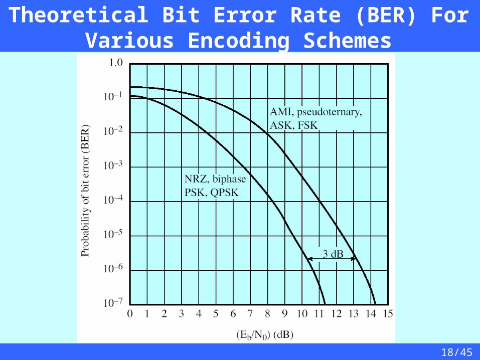
Disadvantagesreceiver distinguishes between three levels: +A, -A, 0a 3 level system could represent log23 = 1.58 bits
requires approx. 3dB more signal power for same probability of bit error
18/45
Theoretical Bit Error Rate (BER) For Various Encoding Schemes

19/45
Manchester Encoding
has transition in middle of each bit periodlow to high represents binary onetransition serves as clock and datahigh to low represents binary zeroused by IEEE 802.3 (Ethernet) LAN standard

20/45
Differential Manchester Encoding
midbit transition is clocking onlytransition at start of bit period representing binary 0no transition at start of bit period representing binary 1used by IEEE 802.5 token ring LAN
21/45
Advantages and disadvantages of Manchester Encoding
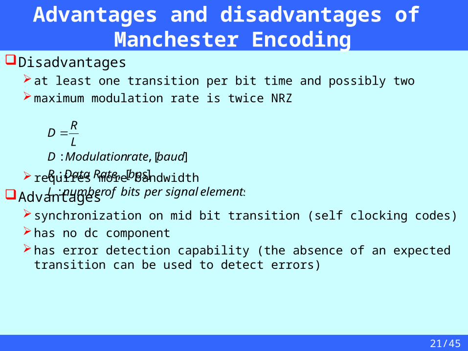
Disadvantagesat least one transition per bit time and possibly twomaximum modulation rate is twice NRZ
requires more bandwidth
Advantagessynchronization on mid bit transition (self clocking codes)has no dc componenthas error detection capability (the absence of an expected transition can be
used to detect errors)
elementssignalperbitsofnumberL
bpsRateDataR
baudrateModulationDL
RD
:
][,:
][,:

22/45
Modulation Rate versus Data RateData rate (expressed in bps)
Data rate or bit rate R=1/Tb=1/1μs=1Mbps
Modulation Rate (expressed in baud) is the rate at which signal elements are generatedMaximum modulation rate
for Manchester is D=1/(0.5Tb)=2/1μs=2Mbaud
23/45
Scrambling
Use scrambling to replace sequences that would produce constant voltage
These filling sequences mustproduce enough transitions to maintain synchronizationbe recognized by receiver & replaced with originalbe same length as original
Design goalshave no dc componenthave no long sequences of zero level line signalhave no reduction in data rategive error detection capability
24/45
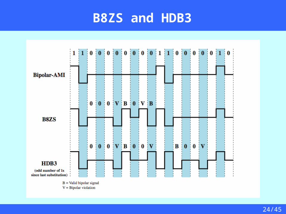
B8ZS and HDB3
25/45
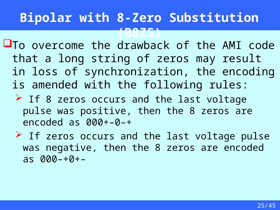
Bipolar with 8-Zero Substitution (B8ZS)
To overcome the drawback of the AMI code that a long string of zeros may result in loss of synchronization, the encoding is amended with the following rules: If 8 zeros occurs and the last voltage pulse was positive,
then the 8 zeros are encoded as 000+–0–+ If zeros occurs and the last voltage pulse was negative,
then the 8 zeros are encoded as 000–+0+–
26/45
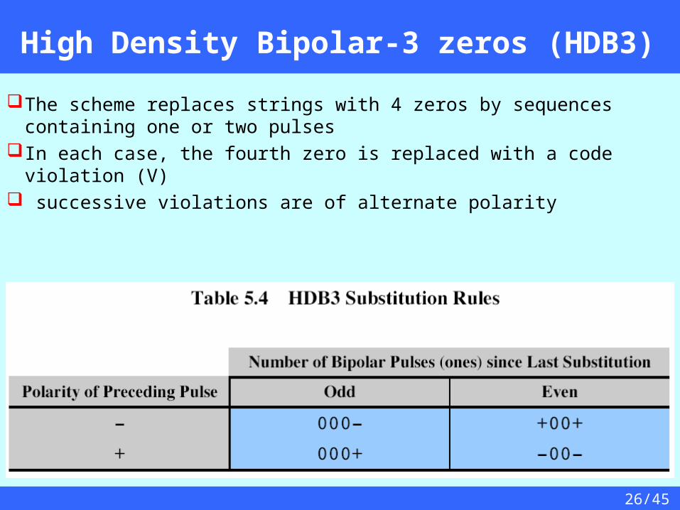
High Density Bipolar-3 zeros (HDB3)
The scheme replaces strings with 4 zeros by sequences containing one or two pulses
In each case, the fourth zero is replaced with a code violation (V) successive violations are of alternate polarity
27/45
Digital Data, Analog Signal
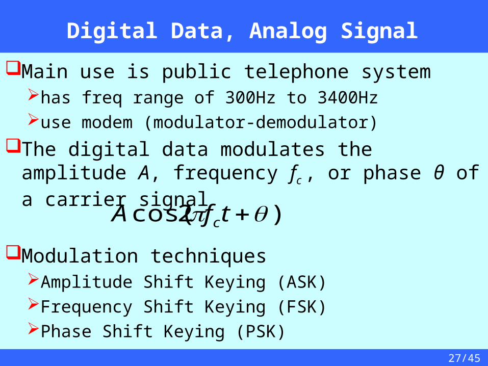
Main use is public telephone systemhas freq range of 300Hz to 3400Hzuse modem (modulator-demodulator)
The digital data modulates the amplitude A, frequency fc , or phase θ of a carrier signal
Modulation techniquesAmplitude Shift Keying (ASK)Frequency Shift Keying (FSK)Phase Shift Keying (PSK)
)2cos( tfA c
28/45
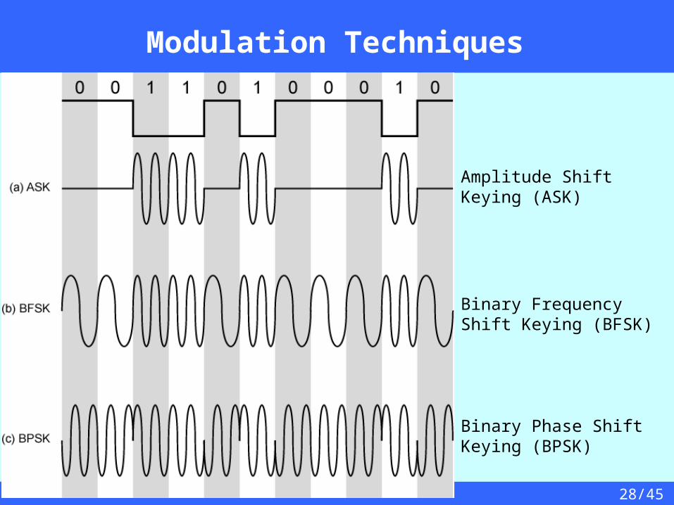
Modulation Techniques
Amplitude Shift Keying (ASK)
Binary Frequency Shift Keying (BFSK)
Binary Phase Shift Keying (BPSK)
29/45
Amplitude Shift Keying (ASK)
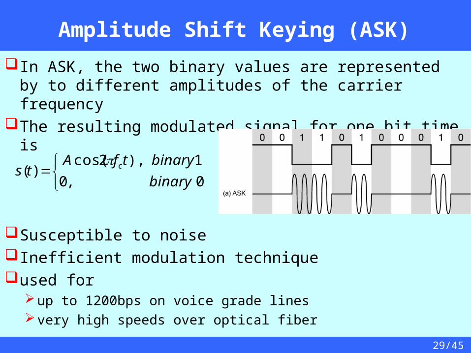
In ASK, the two binary values are represented by to different amplitudes of the carrier frequency
The resulting modulated signal for one bit time is
Susceptible to noiseInefficient modulation techniqueused for
up to 1200bps on voice grade linesvery high speeds over optical fiber
0,0
1),2cos()(
binary
binarytfAts c

30/45
Binary Frequency Shift Keying (BFSK)
The most common form of FSK is Binary FSK (BFSK)Two binary values represented by two different frequencies ( f1 and
f2 )
less susceptible to noise than ASKused for
up to 1200bps on voice grade lineshigh frequency radio (3 to 30MHz)even higher frequency on LANs using coaxial cable
0),2cos(
1),2cos()(
2
1
binarytfA
binarytfAts
0 0 1 1 0 1 0 0 0 1 0
f2 f2 f1 f1 f2 f1 f2 f2 f2 f1 f2
31/45
Full-Duplex BFSK Transmission on a Voice-Grade line
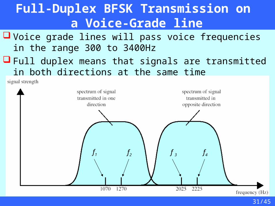
Voice grade lines will pass voice frequencies in the range 300 to 3400Hz
Full duplex means that signals are transmitted in both directions at the same time
f1 f 3 f4f2
32/45
Multiple FSK (MFSK)
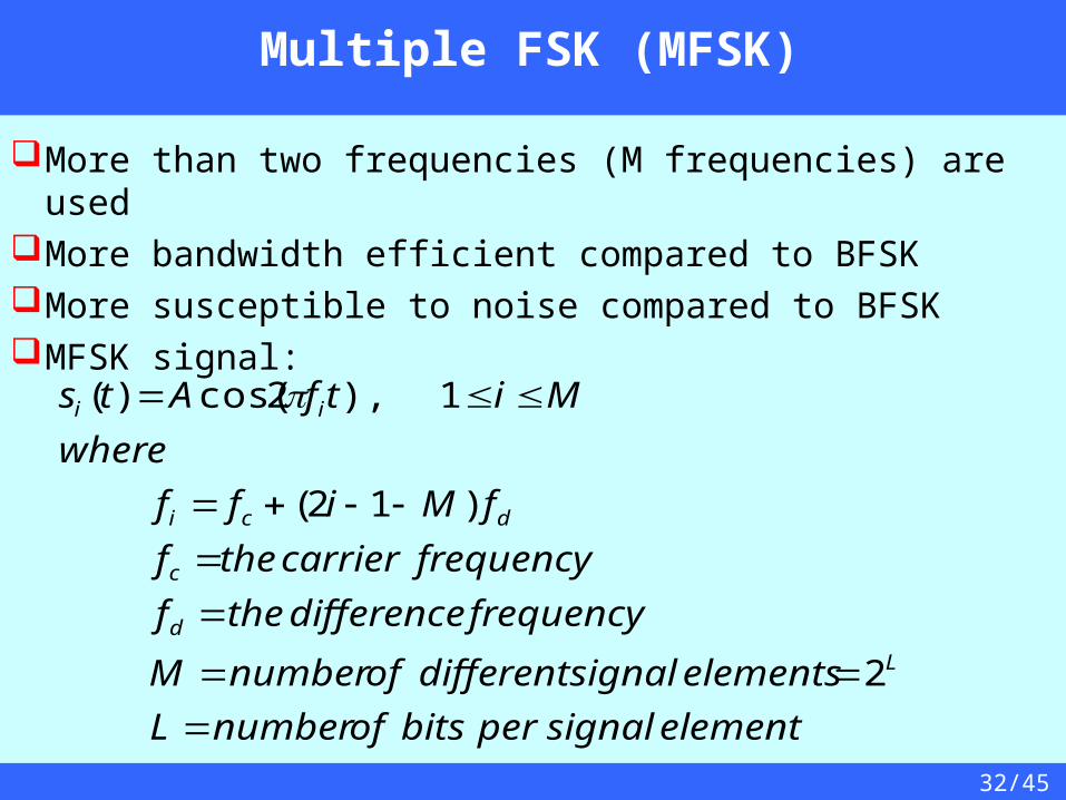
More than two frequencies (M frequencies) are usedMore bandwidth efficient compared to BFSKMore susceptible to noise compared to BFSKMFSK signal:
elementsignalperbitsofnumberL
elementssignaldifferentofnumberM
frequencydifferencethef
frequencycarrierthef
fMiff
where
MitfAts
L
d
c
dci
ii
2
)12(
1),2cos()(
33/45
Multiple FSK (MFSK)
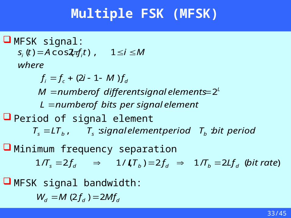
MFSK signal:
Period of signal element
Minimum frequency separation
MFSK signal bandwidth:
elementsignalperbitsofnumberL
elementssignaldifferentofnumberM
fMiff
where
MitfAts
L
dci
ii
2
)12(
1),2cos()(
ddd MffMW 2)2(
periodbitTperiodelementsignalTLTT bsbs ::,
)(2/12)/(12/1 ratebitLfTfLTfT dbdbds
34/45
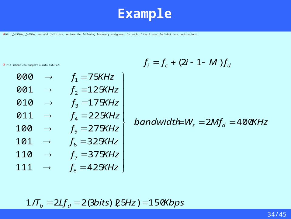
Example With fc=250KHz, fd=25KHz, and M=8 (L=3 bits), we have the following frequency assignment for each of the 8 possible 3-bit data combinations:
This scheme can support a data rate of:
KHzMfWbandwidth
KHzf
KHzf
KHzf
KHzf
KHzf
KHzf
KHzf
KHzf
ds 4002
425111
375110
325101
275100
225011
175010
125001
75000
8
7
6
5
4
3
2
1
KbpsHzbitsLfT db 150)25)(3(22/1
dci fMiff )12(
35/45
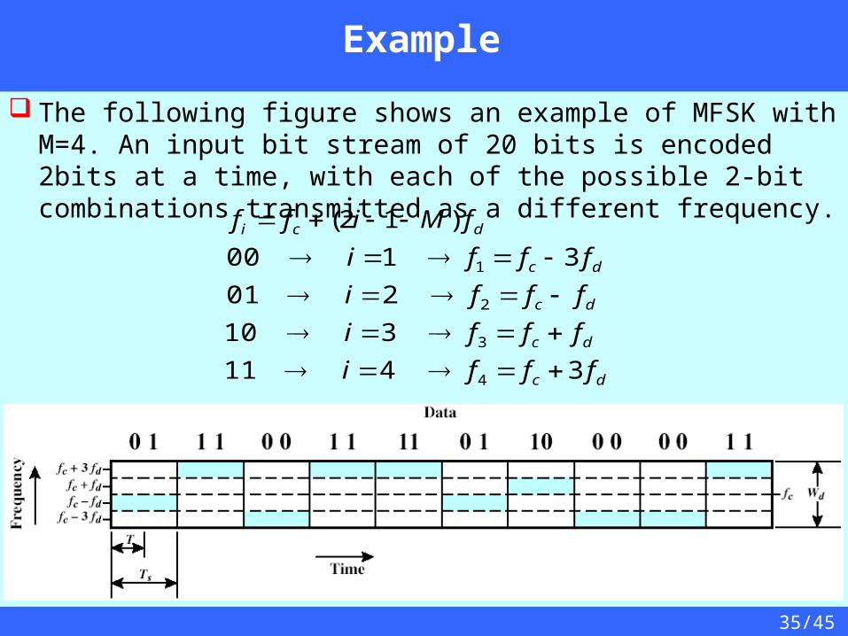
Example
The following figure shows an example of MFSK with M=4. An input bit stream of 20 bits is encoded 2bits at a time, with each of the possible 2-bit combinations transmitted as a different frequency.
dc
dc
dc
dc
dci
fffi
fffi
fffi
fffi
fMiff
3411
310
201
3100
)12(
4
3
2
1
36/45
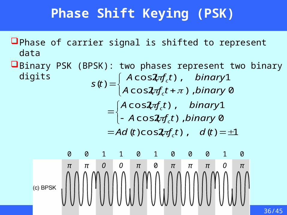
Phase Shift Keying (PSK)
Phase of carrier signal is shifted to represent dataBinary PSK (BPSK): two phases represent two
binary digits
0 0 1 1 0 1 0 0 0 1 0
π π 0 0 π 0 π π π 0 π
1)(),2cos()(
0),2cos(
1),2cos(
0),2cos(
1),2cos()(
tdtftAd
binarytfA
binarytfA
binarytfA
binarytfAts
c
c
c
c
c
37/45
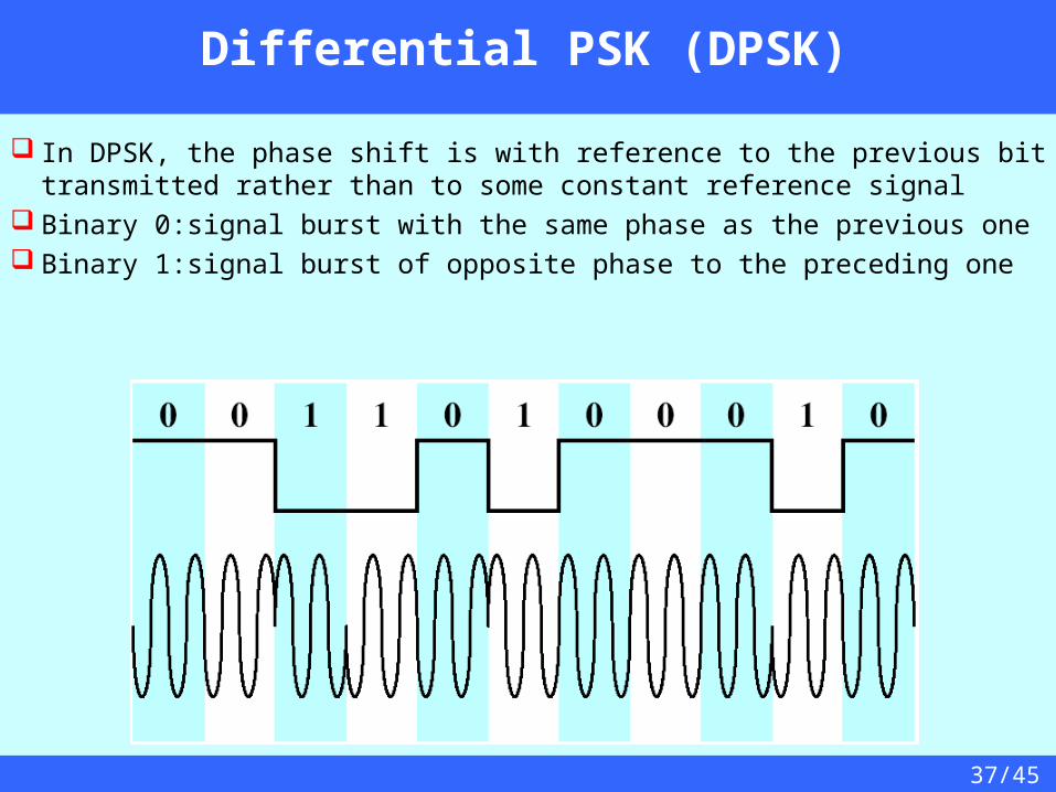
Differential PSK (DPSK)
In DPSK, the phase shift is with reference to the previous bit transmitted rather than to some constant reference signal
Binary 0:signal burst with the same phase as the previous one Binary 1:signal burst of opposite phase to the preceding one

38/45
Four-level PSK: Quadrature PSK (QPSK)
10)4
2cos(
00)4
32cos(
01)4
32cos(
11)4
2cos(
)(
tfA
tfA
tfA
tfA
ts
c
c
c
c
More efficient use of bandwidth if each signal element represents more than one bit eg. shifts of /2 (90o) each signal element represents two bits split input data stream in two & modulate onto the phase of the carrier
can use 8 phase angles & more than one amplitude 9600bps modem uses 12 phase angles, four of which have two
amplitudes: this gives a total of 16 different signal elements
39/45
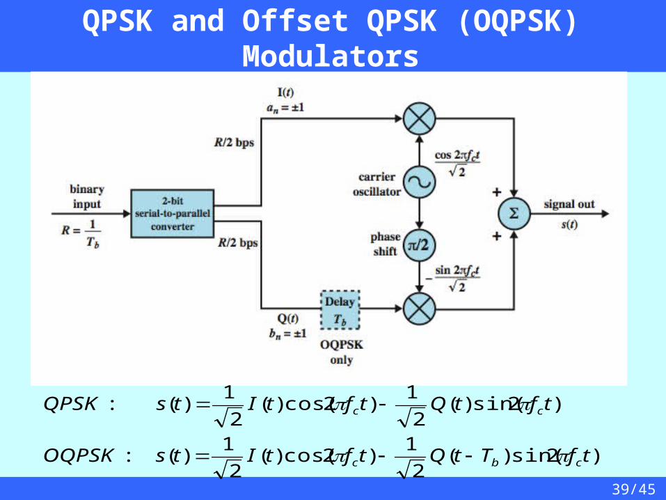
QPSK and Offset QPSK (OQPSK) Modulators
)2sin()(2
1)2cos()(
2
1)(:
)2sin()(2
1)2cos()(
2
1)(:
tfTtQtftItsOQPSK
tftQtftItsQPSK
cbc
cc
40/45
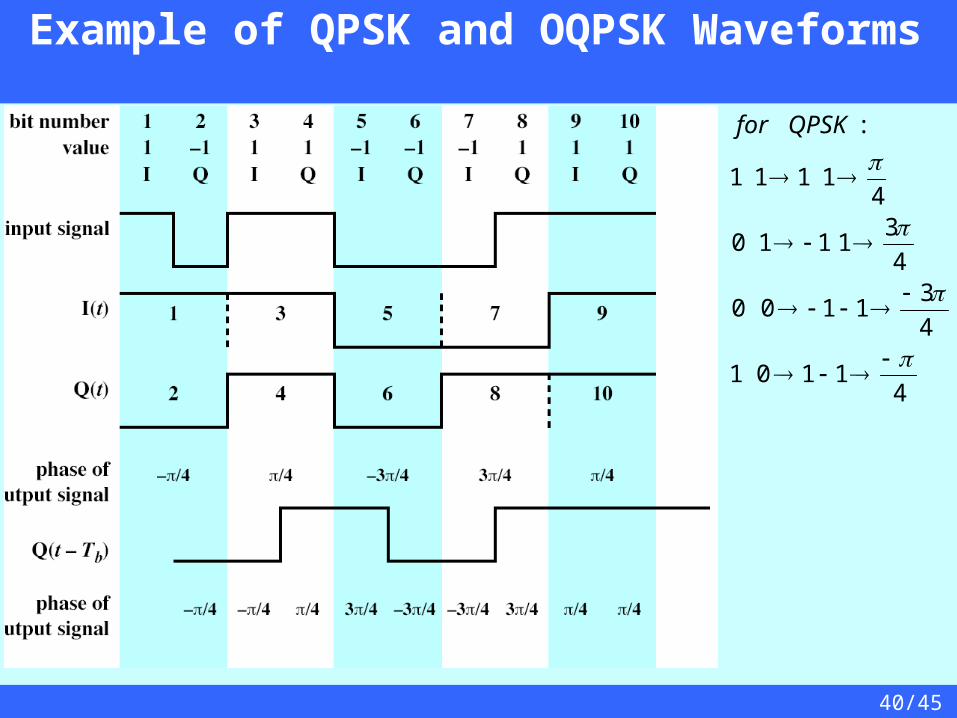
Example of QPSK and OQPSK Waveforms
41101
4
31100
4
31110
41111
:
QPSKfor
41/45
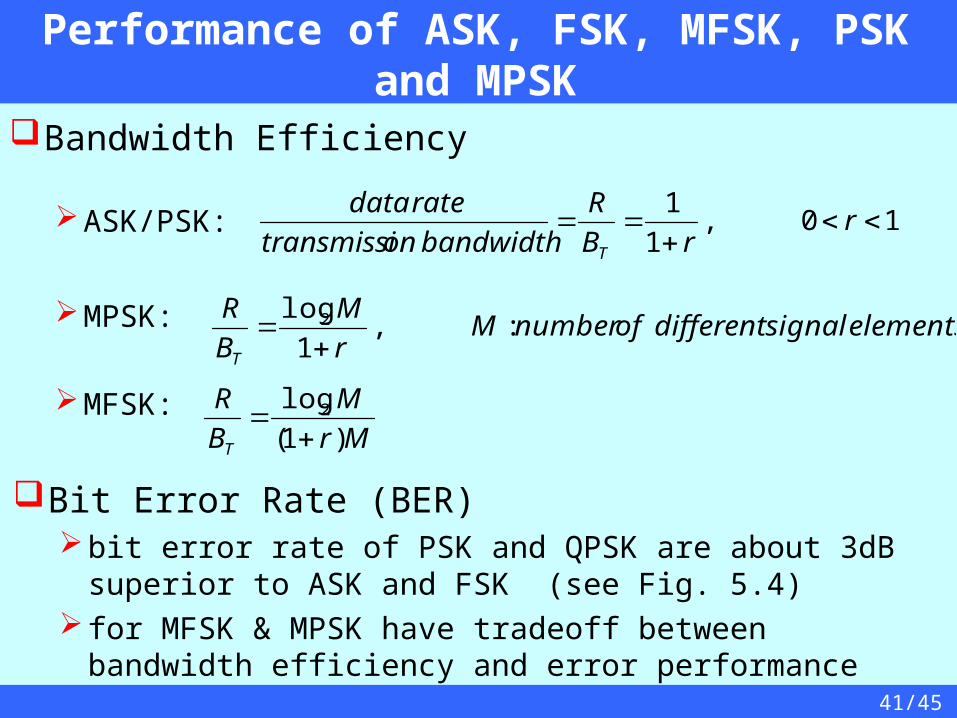
Performance of ASK, FSK, MFSK, PSK and MPSK
Bandwidth Efficiency
ASK/PSK:
MPSK:
MFSK:
10,1
1
r
rB
R
bandwidthontransmissi
ratedata
T
elementssignaldifferentofnumberMr
M
B
R
T
:,1
log2
Mr
M
B
R
T )1(
log2
Bit Error Rate (BER)bit error rate of PSK and QPSK are about 3dB superior to
ASK and FSK (see Fig. 5.4) for MFSK & MPSK have tradeoff between bandwidth
efficiency and error performance
42/45
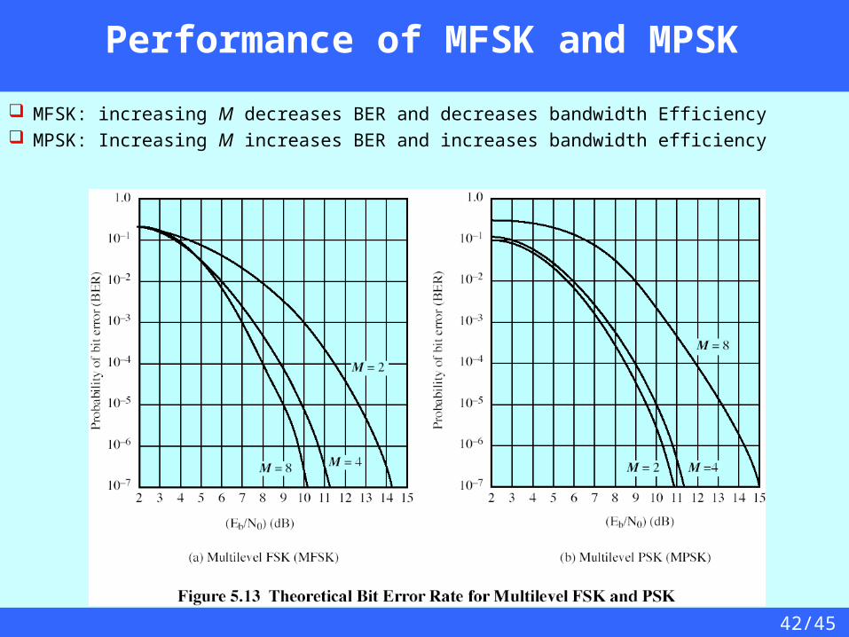
Performance of MFSK and MPSK
MFSK: increasing M decreases BER and decreases bandwidth Efficiency MPSK: Increasing M increases BER and increases bandwidth efficiency

43/45
Quadrature Amplitude Modulation (QAM)
QAM used on asymmetric digital subscriber line (ADSL) and some wireless standards
combination of ASK and PSKlogical extension of QPSKsend two different signals simultaneously on
same carrier frequencyuse two copies of carrier, one shifted by 90°
each carrier is ASK modulated

44/45
QAM modulator
ASK
c
ASK
c tftdtftdtsQAM )2sin()()2cos()()(: 21
45/45
QAM Variants
Two level ASK (two different amplitude levels)each of two streams in one of two statesfour state systemessentially QPSK
Four level ASK (four different amplitude levels)combined stream in one of 16 states
Have 64 and 256 state systems Improved data rate for given bandwidth
but increased potential error rate