2 prismaflex crrt basic components - seg 2
DESCRIPTION
TRANSCRIPT

PrismaFlex ® STEPP
•Basic Components

Hemofilter
Basic Components in CRRT
CRRT
Blood WarmerVascular access
Anticoagulation
CRRT System
Solutions

Access: Location
• Internal Jugular Vein –
• Lower risk of complication
• Simplicity of catheter insertion
• Femoral Vein –
• Optimal site for immobilized patient
• Easiest site for insertion
• Subclavian Vein –
• Higher risk of pneumo/hemothorax
• Associated with central venous stenosis
A veno-venous double or two single lumen venous catheters

Access: Important Considerations
• Refer to and follow the hospital protocol for specific guidelines
• Vascular Access ADQI* recommendations:
• Aspirate and discard heparin before flushing
• 20 to 30 CC syringe to assess patency
• Check for kinks/ clamps
*www.adqi.net

Anticoagulation
Commonly utilized:
• Heparin
• Citrate

Purpose of Warmers in CRRT
• Prevent heat loss
• Minimize calorie loss
• Patient comfort
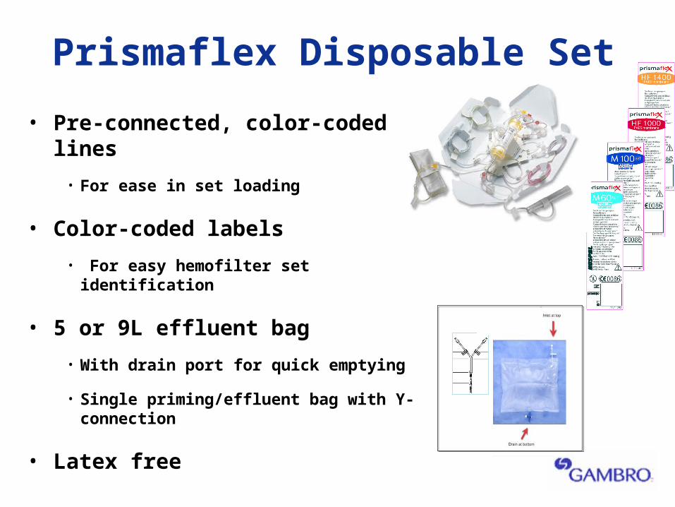
Prismaflex Disposable Set
• Pre-connected, color-coded lines
• For ease in set loading
• Color-coded labels
• For easy hemofilter set identification
• 5 or 9L effluent bag
• With drain port for quick emptying
• Single priming/effluent bag with Y- connection
• Latex free

Prismaflex Disposable Set
• Single set for all therapy modalities
• Multiple sites for replacement fluid infusion
• Integrated pre-blood pump (PBP) infusion to the access line
• High flow blood lines with minimal pressure drop
• Clear Plastic Pump Cover
• Easy visibility of blood/fluid pump segments
• Electrostatic Discharger Ring
• To minimize ECG artifacts
• Integrated Barcode Reader
• For set recognition and automatic alarm limit settings

Prismaflex Disposable Set
• Pressure pods
• No blood-air interface to minimize clotting
• Patented Deaeration/Monitoring System
• Unique deaeration chamber with spinning cylinder
• Bottom to top flow propels air bubbles upwards for automatic removal
• Post-replacement fluid layer eliminates air/blood interface
• Return pressure monitoring
• Small blood volume ~8 ml

Prismaflex Disposable Set: Specifications
Sets Surface Area (m2)
BFR (ml/min)
DFR (ml/hr)
Priming Volume
(ml)
Blood Volume
(ml)
Max Filtration Capacity (ml/hr)
M60* 0.6 50-180 0-4000 1000 93 4000-pre
3000-post
2000-pbp
M100 0.9 75-400 0-8000 1000 152 8000-pre
6000-post
4000-pbp
HF1000 1.15 75-400 0-8000 1000 165
HF1400 1.4 75-400 0-8000 2000 186
*Indicated for patients >11kg

Solutions for CRRT
Purpose • Dialysate and/or Replacement – provide diffusion and/or
convection
• Depends on mode of therapy
• Removal of unwanted solutes
• Restores electrolyte and acid/base balance to patient’s blood.
Buffer • Normalize blood pH
• Balances ongoing endogenous acid production
• Treat underlying metabolic acidosis/alkalosis
• Replace bicarbonate lost during CRRT

Gambro Solution Options
Use as dialysate solution Use as replacement solutionPrismaSol

Composition

PrismaSol®
Composition

Preparation of Solution
5L ready-to-use solution obtained after breaking red frangible pin between two compartments

Prismaflex ® System
Overview
The Next Generation Continuous Blood
Purification Technology

The Prismaflex® System
•Communication Unit
•Flow Control Unit
•Fluid Control Unit

®
Communication Unit
• Interactive, color, touch screen
• Machine status lights

Interactive Display Screen Step-by-Step Instructions
•12 in. colored touch-screen•Displays a color-coded diagram of required actions

Status Lights
• Green - normal treatment conditions
• Yellow - advisory or caution alarm
• Red - highest priority alarm condition needing immediate intervention
Give a general indication of operating conditions.

®
Flow Control Unit
• Blood and fluid pumps
• Syringe pump
• Pressure monitoring system
• Pinch valves
• Safety feature components
Prismaflex® Operator’s Manual Chapter 1, p.1-2
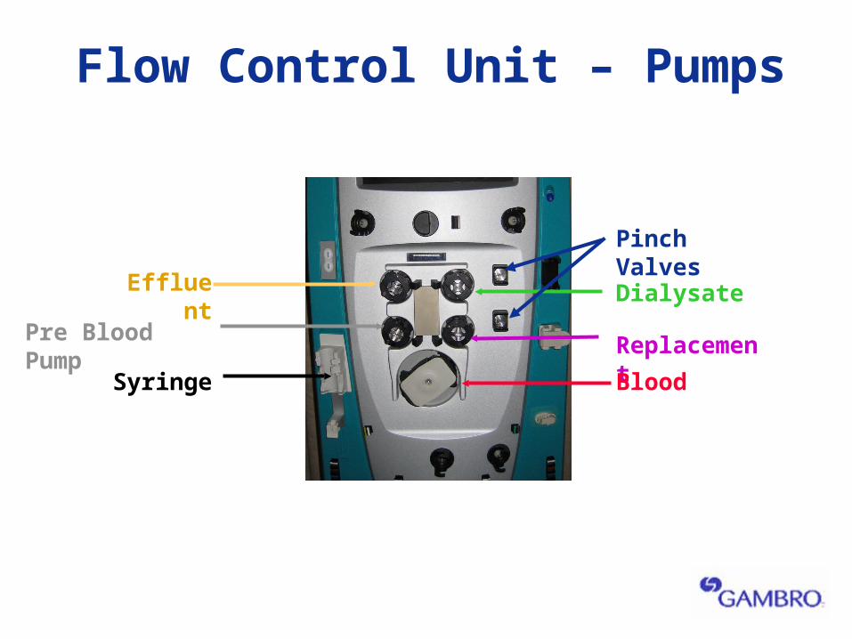
Effluent
Pre Blood Pump Replacement
Blood
Flow Control Unit – Pumps
Syringe
Dialysate
Pinch Valves

Effluent
Filter
Return
Access
Flow Control Unit Pressure Monitoring

Pressure Monitoring
Pressure Pods
To Software
PressureSensor
Air side
Bloodline
DiaphragmPressure PodFluid side
Front Panel
Prismaflex® Operator’s Manual Chapter 4-p52
Pressure Pod System
Return Pressure Monitor
Pressure Port
Monitor Line
Deaeration
Chamber

Blood Leak Detector
Air Bubble Detector
Return LineClamp
Safety Components
Deaeration Chamber Holder
Bar Code Reader
ECG Discharger Ring

Flow Control Unit:Deaeration Chamber
• Allows semi-automatic
air removal
• Post dilution fluid layer (~200mL/hr)
eliminates air blood interface

Flow Rates Summary
SCUF CVVH CVVHD CVVHDF
Principles UF UF,Con UF,Diff UF,Diff, Con
Blood Flow (ml/min) 450 450 450 450
Pt Fluid Removal 2 L/hr 2L/hr 2L/hr 2L/hr
Dialysate 0 0 8L/hr 8L/hr
Replacement 0 8L/hr 0 8L/hr
PBP 1L/hr 8L/hr 8L/hr 8L/hr
Note: Total Effluent Volume 10L/hr
®
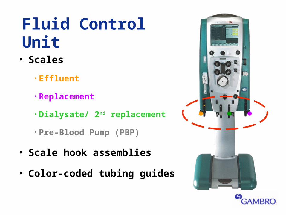
Fluid Control Unit
• Scales
• Effluent
• Replacement
• Dialysate/ 2nd replacement
• Pre-Blood Pump (PBP)
• Scale hook assemblies
• Color-coded tubing guides

Fluid Control Unit• Scale hook assembly
• Slide-out bar tray
• Removable carrying bar
• Scales-
• Effluent
• Pre-blood pump (PBP)
• Dialysate
• Replacement