2000 nissan xterra - automatic transmission service manual
DESCRIPTION
This is the repair/service manual for the 2000-01 Nissan Xterra manual transmission.TRANSCRIPT
AUTOMATIC TRANSMISSION
SECTIONATCONTENTS
TROUBLE DIAGNOSIS - INDEX ....................................4Alphabetical & P No. Index for DTC ...........................4
PRECAUTIONS ...............................................................6Supplemental Restraint System (SRS) ″AIRBAG″ and ″SEAT BELT PRE-TENSIONER″...............6Precautions for On Board Diagnostic (OBD)System of A/T and Engine...........................................6Precautions ..................................................................6Service Notice or Precautions .....................................8Wiring Diagrams and Trouble Diagnosis.....................9
PREPARATION .............................................................10Special Service Tools ................................................10
OVERALL SYSTEM ......................................................12A/T Electrical Parts Location .....................................12Circuit Diagram..........................................................13Cross-sectional View .................................................14Hydraulic Control Circuit............................................15Shift Mechanism ........................................................16Control System ..........................................................25Control Mechanism....................................................26Control Valve .............................................................31
ON BOARD DIAGNOSTIC SYSTEMDESCRIPTION ...............................................................33
Introduction ................................................................33OBD-II Function for A/T System................................33One or Two Trip Detection Logic of OBD-II ..............33OBD-II Diagnostic Trouble Code (DTC) ....................33Malfunction Indicator Lamp (MIL)..............................37CONSULT-II ...............................................................37Diagnostic Procedure Without CONSULT-II..............46
TROUBLE DIAGNOSIS - INTRODUCTION ..................53Introduction ................................................................53Work Flow..................................................................57
TROUBLE DIAGNOSIS - BASIC INSPECTION ...........59A/T Fluid Check .........................................................59Stall Test ....................................................................59Line Pressure Test.....................................................62Road Test...................................................................63
TROUBLE DIAGNOSIS - GENERALDESCRIPTION ...............................................................81
Symptom Chart..........................................................81TCM Terminals and Reference Value........................92
TROUBLE DIAGNOSIS FOR POWER SUPPLY ..........96Wiring Diagram - AT - MAIN......................................96
DTC P0705 PARK/NEUTRAL POSITION (PNP)SWITCH .........................................................................99
Description .................................................................99Wiring Diagram - AT - PNP/SW...............................101Diagnostic Procedure ..............................................102Component Inspection.............................................104
DTC P0710 A/T FLUID TEMPERATURE SENSORCIRCUIT .......................................................................105
Description ...............................................................105Wiring Diagram - AT - FTS......................................107Diagnostic Procedure ..............................................108Component Inspection.............................................110
DTC P0720 VEHICLE SPEED SENSOR.A/T(REVOLUTION SENSOR) ........................................... 111
Description ............................................................... 111Wiring Diagram - AT - VSSA/T................................113Diagnostic Procedure ..............................................114Component Inspection.............................................115
DTC P0725 ENGINE SPEED SIGNAL .......................116Description ...............................................................116Wiring Diagram - AT - ENGSS ................................117Diagnostic Procedure ..............................................118
DTC P0731 IMPROPER SHIFTING TO 1ST GEARPOSITION ....................................................................120
Description ...............................................................120Wiring Diagram - AT - 1ST ......................................123Diagnostic Procedure ..............................................124Component Inspection.............................................125
DTC P0732 IMPROPER SHIFTING TO 2ND GEARPOSITION ....................................................................126
Description ...............................................................126Wiring Diagram - AT - 2ND......................................129Diagnostic Procedure ..............................................130
GI
MA
EM
LC
EC
FE
CL
MT
TF
PD
AX
SU
BR
ST
RS
BT
HA
SC
EL
IDX
Component Inspection.............................................130DTC P0733 IMPROPER SHIFTING TO 3RD GEARPOSITION ....................................................................132
Description ...............................................................132Wiring Diagram - AT - 3RD......................................135Diagnostic Procedure ..............................................136Component Inspection.............................................136
DTC P0734 IMPROPER SHIFTING TO 4TH GEARPOSITION ....................................................................138
Description ...............................................................138Wiring Diagram - AT - 4TH......................................142Diagnostic Procedure ..............................................143Component Inspection.............................................146
DTC P0740 TORQUE CONVERTER CLUTCHSOLENOID VALVE ......................................................147
Description ...............................................................147Wiring Diagram - AT - TCV......................................149Diagnostic Procedure ..............................................150Component Inspection.............................................151
DTC P0744 IMPROPER LOCK-UP OPERATION ......152Description ...............................................................152Wiring Diagram - AT - TCCSIG ...............................155Diagnostic Procedure ..............................................156Component Inspection.............................................159
DTC P0745 LINE PRESSURE SOLENOID VALVE ...160Description ...............................................................160Wiring Diagram - AT - LPSV....................................162Diagnostic Procedure ..............................................163Component Inspection.............................................164
DTC P0750 SHIFT SOLENOID VALVE A ..................165Description ...............................................................165Wiring Diagram - AT - SSV/A ..................................167Diagnostic Procedure ..............................................168Component Inspection.............................................169
DTC P0755 SHIFT SOLENOID VALVE B ..................170Description ...............................................................170Wiring Diagram - AT - SSV/B ..................................172Diagnostic Procedure ..............................................173Component Inspection.............................................174
DTC P1705 THROTTLE POSITION SENSOR ...........175Description ...............................................................175Wiring Diagram - AT - TPS......................................178Diagnostic Procedure ..............................................179Component Inspection.............................................183
DTC P1760 OVERRUN CLUTCH SOLENOIDVALVE ..........................................................................184
Description ...............................................................184Wiring Diagram - AT - OVRCSV..............................186Diagnostic Procedure ..............................................187Component Inspection.............................................188
DTC BATT/FLUID TEMP SEN (A/T FLUID TEMPSENSOR CIRCUIT AND TCM POWER SOURCE) ....189
Description ...............................................................189Wiring Diagram - AT - BA/FTS ................................191Diagnostic Procedure ..............................................192Component Inspection.............................................194
VEHICLE SPEED SENSOR.MTR ................................195Description ...............................................................195Wiring Diagram - AT - VSSMTR..............................197Diagnostic Procedure ..............................................198
DTC CONTROL UNIT (RAM), CONTROL UNIT(ROM)...........................................................................199
Description ...............................................................199Diagnostic Procedure ..............................................200
DTC CONTROL UNIT (EEPROM) ..............................201Description ...............................................................201Diagnostic Procedure ..............................................202
TROUBLE DIAGNOSES FOR SYMPTOMS ...............203Wiring Diagram - AT - NONDTC .............................2031. O/D OFF Indicator Lamp Does Not Come On....2062. Engine Cannot Be Started In P and N Position..2083. In ″P″ Position, Vehicle Moves Forward OrBackward When Pushed .........................................2094. In N Position, Vehicle Moves ..............................2105. Large Shock. N -> R Position .............................2126. Vehicle Does Not Creep Backward In RPosition ....................................................................2147. Vehicle Does Not Creep Forward In D, 2 Or 1Position ....................................................................2178. Vehicle Cannot Be Started From D1 ...................2209. A/T Does Not Shift: D1 -> D2 Or Does NotKickdown: D4 -> D2..................................................22310. A/T Does Not Shift: D2 -> D3.............................22611. A/T Does Not Shift: D3 -> D4.............................22912. A/T Does Not Perform Lock-up .........................23213. A/T Does Not Hold Lock-up Condition ..............23414. Lock-up Is Not Released...................................23615. Engine Speed Does Not Return To Idle (LightBraking D4 -> D3).....................................................23716. Vehicle Does Not Start From D1 .......................23917. A/T Does Not Shift: D4 -> D3, WhenOverdrive Control Switch ON -> OFF .....................24018. A/T Does Not Shift: D3 -> 22, When SelectorLever D -> 2 Position ..............................................24119. A/T Does Not Shift: 22 -> 11, When SelectorLever 2 -> 1 Position ...............................................24220. Vehicle Does Not Decelerate By EngineBrake........................................................................24321. TCM Self-diagnosis Does Not Activate (PNP,Overdrive Control and Throttle Position SwitchesCircuit Checks) ........................................................243
A/T SHIFT LOCK SYSTEM .........................................251Description ...............................................................251Wiring Diagram - SHIFT -........................................252
CONTENTS (Cont’d)
AT-2
Diagnostic Procedure ..............................................253Component Check ...................................................255
KEY INTERLOCK CABLE ..........................................256Components.............................................................256Removal...................................................................256Installation................................................................257
ON-VEHICLE SERVICE ..............................................258Control Valve Assembly and Accumulators.............258Revolution Sensor Replacement .............................259Rear Oil Seal Replacement.....................................259Parking Components Inspection..............................259Park/Neutral Position (PNP) Switch Adjustment .....260Manual Control Linkage Adjustment........................260
REMOVAL AND INSTALLATION ...............................261Removal...................................................................261Installation................................................................263
OVERHAUL .................................................................264Components.............................................................264Oil Channel ..............................................................266Locations of Needle Bearings, Thrust Washersand Snap Rings .......................................................267
DISASSEMBLY ............................................................268REPAIR FOR COMPONENT PARTS .........................279
Oil Pump..................................................................279Control Valve Assembly...........................................283Control Valve Upper Body .......................................289
Control Valve Lower Body .......................................294Reverse Clutch ........................................................296High Clutch ..............................................................300Forward and Overrun Clutches ...............................302Low & Reverse Brake..............................................306Forward Clutch Drum Assembly..............................310Rear Internal Gear and Forward Clutch Hub..........312Band Servo Piston Assembly ..................................315Parking Pawl Components ......................................319
ASSEMBLY ..................................................................321Assembly (1)............................................................321Adjustment ...............................................................329Assembly (2)............................................................331
SERVICE DATA AND SPECIFICATIONS (SDS) .......338General Specifications.............................................338Shift Schedule..........................................................338Stall Revolution........................................................338Line Pressure...........................................................338Return Springs.........................................................339Accumulator O-ring..................................................340Clutches and Brakes ...............................................340Oil Pump and Low One-way Clutch ........................342Total End Play..........................................................342Reverse Clutch Drum End Play ..............................343Removal and Installation .........................................343
GI
MA
EM
LC
EC
FE
CL
MT
TF
PD
AX
SU
BR
ST
RS
BT
HA
SC
EL
IDX
CONTENTS (Cont’d)
AT-3
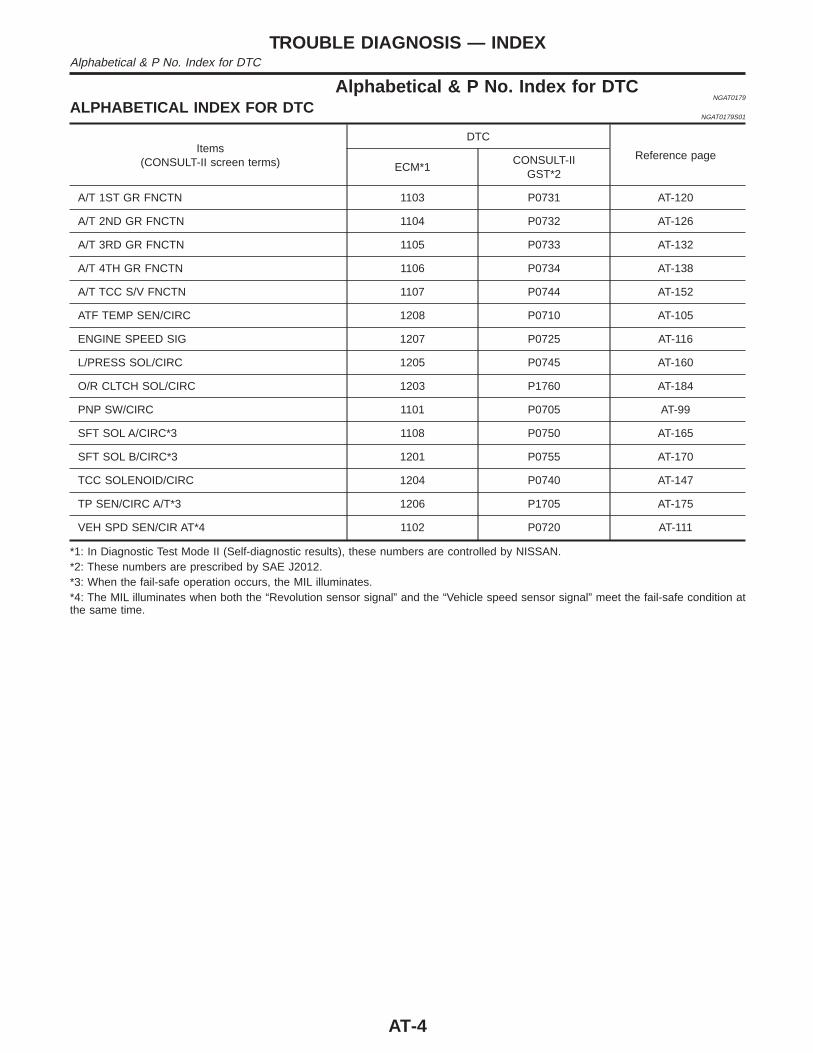
Alphabetical & P No. Index for DTCNGAT0179
ALPHABETICAL INDEX FOR DTCNGAT0179S01
Items(CONSULT-II screen terms)
DTC
Reference pageECM*1
CONSULT-IIGST*2
A/T 1ST GR FNCTN 1103 P0731 AT-120
A/T 2ND GR FNCTN 1104 P0732 AT-126
A/T 3RD GR FNCTN 1105 P0733 AT-132
A/T 4TH GR FNCTN 1106 P0734 AT-138
A/T TCC S/V FNCTN 1107 P0744 AT-152
ATF TEMP SEN/CIRC 1208 P0710 AT-105
ENGINE SPEED SIG 1207 P0725 AT-116
L/PRESS SOL/CIRC 1205 P0745 AT-160
O/R CLTCH SOL/CIRC 1203 P1760 AT-184
PNP SW/CIRC 1101 P0705 AT-99
SFT SOL A/CIRC*3 1108 P0750 AT-165
SFT SOL B/CIRC*3 1201 P0755 AT-170
TCC SOLENOID/CIRC 1204 P0740 AT-147
TP SEN/CIRC A/T*3 1206 P1705 AT-175
VEH SPD SEN/CIR AT*4 1102 P0720 AT-111
*1: In Diagnostic Test Mode II (Self-diagnostic results), these numbers are controlled by NISSAN.*2: These numbers are prescribed by SAE J2012.*3: When the fail-safe operation occurs, the MIL illuminates.*4: The MIL illuminates when both the “Revolution sensor signal” and the “Vehicle speed sensor signal” meet the fail-safe condition atthe same time.
TROUBLE DIAGNOSIS — INDEXAlphabetical & P No. Index for DTC
AT-4
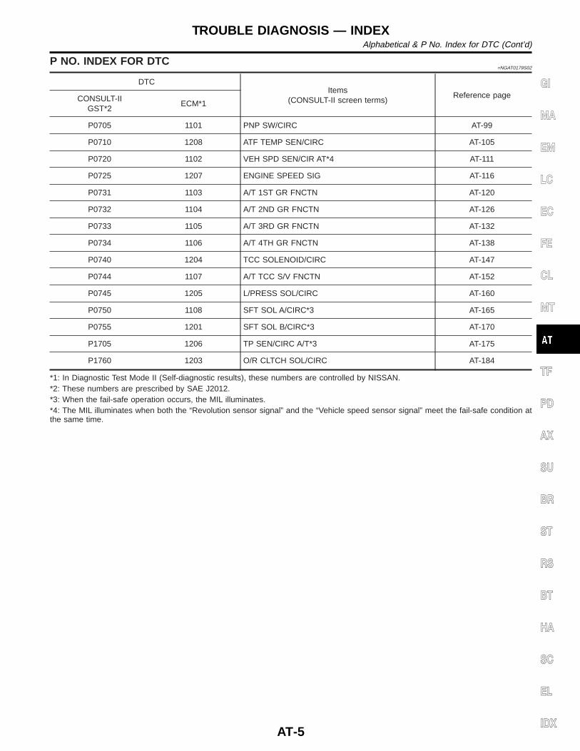
P NO. INDEX FOR DTC=NGAT0179S02
DTCItems
(CONSULT-II screen terms)Reference pageCONSULT-II
GST*2ECM*1
P0705 1101 PNP SW/CIRC AT-99
P0710 1208 ATF TEMP SEN/CIRC AT-105
P0720 1102 VEH SPD SEN/CIR AT*4 AT-111
P0725 1207 ENGINE SPEED SIG AT-116
P0731 1103 A/T 1ST GR FNCTN AT-120
P0732 1104 A/T 2ND GR FNCTN AT-126
P0733 1105 A/T 3RD GR FNCTN AT-132
P0734 1106 A/T 4TH GR FNCTN AT-138
P0740 1204 TCC SOLENOID/CIRC AT-147
P0744 1107 A/T TCC S/V FNCTN AT-152
P0745 1205 L/PRESS SOL/CIRC AT-160
P0750 1108 SFT SOL A/CIRC*3 AT-165
P0755 1201 SFT SOL B/CIRC*3 AT-170
P1705 1206 TP SEN/CIRC A/T*3 AT-175
P1760 1203 O/R CLTCH SOL/CIRC AT-184
*1: In Diagnostic Test Mode II (Self-diagnostic results), these numbers are controlled by NISSAN.*2: These numbers are prescribed by SAE J2012.*3: When the fail-safe operation occurs, the MIL illuminates.*4: The MIL illuminates when both the “Revolution sensor signal” and the “Vehicle speed sensor signal” meet the fail-safe condition atthe same time.
GI
MA
EM
LC
EC
FE
CL
MT
TF
PD
AX
SU
BR
ST
RS
BT
HA
SC
EL
IDX
TROUBLE DIAGNOSIS — INDEXAlphabetical & P No. Index for DTC (Cont’d)
AT-5
Supplemental Restraint System (SRS) “AIRBAG” and “SEAT BELT PRE-TENSIONER”
NGAT0001
The supplemental Restraint System such as “AIR BAG” and “SEAT BELT PRE-TENSIONER” used along witha seat belt, helps to reduce the risk or severity of injury to the driver and front passenger for certain types ofcollision. The Supplemental Restraint System consists of driver air bag module (located in the center of thesteering wheel), front passenger air bag module (located on the instrument panel on passenger side), seatbelt pre-tensioners, a diagnosis sensor unit, a crash zone sensor, warning lamp, wiring harness and spiralcable.Information necessary to service the system safely is included in the RS section of this Service Manual.WARNING:I To avoid rendering the SRS inoperative, which could increase the risk of personal injury or death
in the event of a collision which would result in air bag inflation, all maintenance must be performedby an authorized NISSAN dealer.
I Improper maintenance, including incorrect removal and installation of the SRS, can lead to per-sonal injury caused by unintentional activation of the system. For removal of Spiral Cable and AirBag Module, refer to RS-16.
I Do not use electrical test equipment on any circuit related to the SRS unless instructed to in thisService Manual. Spiral cable and wiring harnesses (except “SEAT BELT PRE-TENSIONER”) cov-ered with yellow insulation either just before the harness connectors or for the complete harnessare related to the SRS.
Precautions for On Board Diagnostic (OBD)System of A/T and Engine
NGAT0002
The ECM has an on board diagnostic system. It will light up the malfunction indicator lamp (MIL) to warn thedriver of a malfunction causing emission deterioration.CAUTION:I Be sure to turn the ignition switch OFF and disconnect the negative battery terminal before any
repair or inspection work. The open/short circuit of related switches, sensors, solenoid valves, etc.will cause the MIL to light up.
I Be sure to connect and lock the connectors securely after work. A loose (unlocked) connector willcause the MIL to light up due to an open circuit. (Be sure the connector is free from water, grease,dirt, bent terminals, etc.)
I Be sure to route and secure the harnesses properly after work. Interference of the harness with abracket, etc. may cause the MIL to light up due to a short circuit.
I Be sure to connect rubber tubes properly after work. A misconnected or disconnected rubber tubemay cause the MIL to light up due to a malfunction of the EGR system or fuel injection system,etc.
I Be sure to erase the unnecessary malfunction information (repairs completed) from the TCM andECM before returning the vehicle to the customer.
SEF289H
PrecautionsNGAT0003
I Before connecting or disconnecting the TCM harnessconnector, turn ignition switch OFF and disconnect nega-tive battery terminal. Failure to do so may damage theTCM. Because battery voltage is applied to TCM even ifignition switch is turned off.
PRECAUTIONSSupplemental Restraint System (SRS) “AIR BAG” and “SEAT BELT PRE-TENSIONER”
AT-6
AAT470A
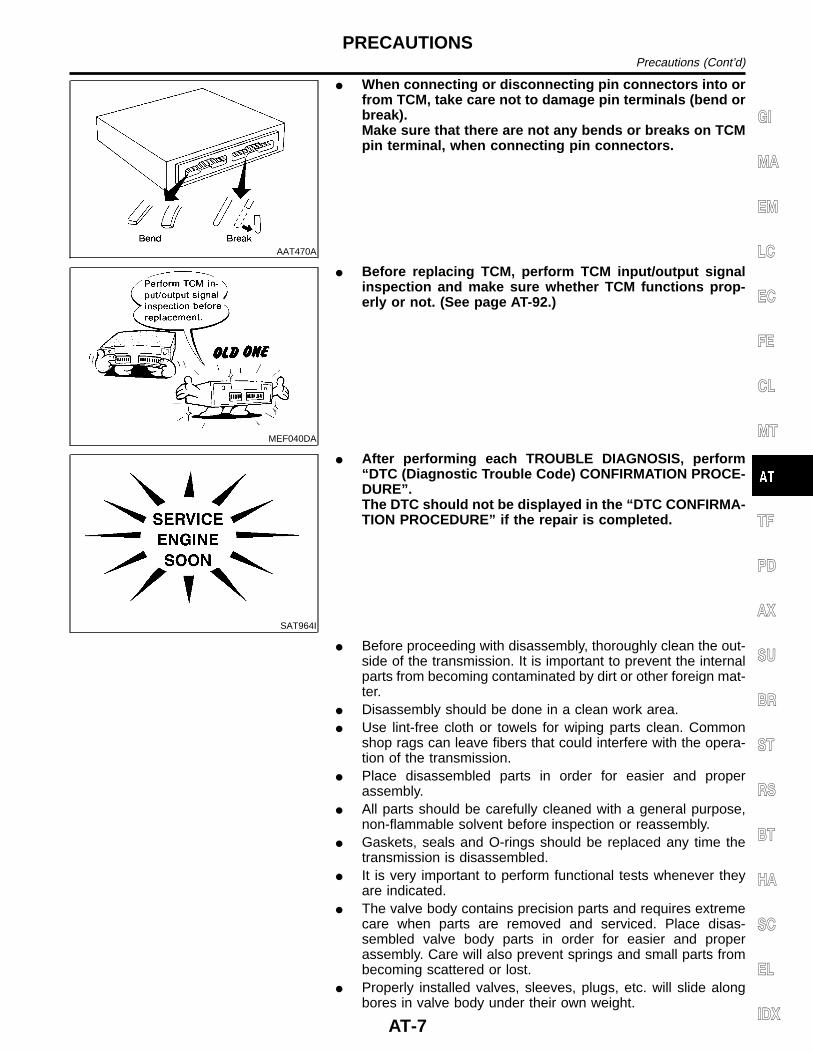
I When connecting or disconnecting pin connectors into orfrom TCM, take care not to damage pin terminals (bend orbreak).Make sure that there are not any bends or breaks on TCMpin terminal, when connecting pin connectors.
MEF040DA
I Before replacing TCM, perform TCM input/output signalinspection and make sure whether TCM functions prop-erly or not. (See page AT-92.)
SAT964I
I After performing each TROUBLE DIAGNOSIS, perform“DTC (Diagnostic Trouble Code) CONFIRMATION PROCE-DURE”.The DTC should not be displayed in the “DTC CONFIRMA-TION PROCEDURE” if the repair is completed.
I Before proceeding with disassembly, thoroughly clean the out-side of the transmission. It is important to prevent the internalparts from becoming contaminated by dirt or other foreign mat-ter.
I Disassembly should be done in a clean work area.I Use lint-free cloth or towels for wiping parts clean. Common
shop rags can leave fibers that could interfere with the opera-tion of the transmission.
I Place disassembled parts in order for easier and properassembly.
I All parts should be carefully cleaned with a general purpose,non-flammable solvent before inspection or reassembly.
I Gaskets, seals and O-rings should be replaced any time thetransmission is disassembled.
I It is very important to perform functional tests whenever theyare indicated.
I The valve body contains precision parts and requires extremecare when parts are removed and serviced. Place disas-sembled valve body parts in order for easier and properassembly. Care will also prevent springs and small parts frombecoming scattered or lost.
I Properly installed valves, sleeves, plugs, etc. will slide alongbores in valve body under their own weight.
GI
MA
EM
LC
EC
FE
CL
MT
TF
PD
AX
SU
BR
ST
RS
BT
HA
SC
EL
IDX
PRECAUTIONSPrecautions (Cont’d)
AT-7
I Before assembly, apply a coat of recommended ATF to allparts. Apply petroleum jelly to protect O-rings and seals, orhold bearings and washers in place during assembly. Do notuse grease.
I Extreme care should be taken to avoid damage to O-rings,seals and gaskets when assembling.
I Replace ATF cooler if excessive foreign material is found in oilpan or clogging strainer. Refer to “ATF COOLER SERVICE”(Refer to AT-9).
I After overhaul, refill the transmission with new ATF.I When the A/T drain plug is removed, only some of the fluid is
drained. Old A/T fluid will remain in torque converter and ATFcooling system.Always follow the procedures under “Changing A/T Fluid” referto MA-37 when changing A/T fluid.
Service Notice or PrecautionsNGAT0004
FAIL-SAFENGAT0004S01
The TCM has an electronic Fail-Safe (limp home mode). This allows the vehicle to be driven even if a majorelectrical input/output device circuit is damaged.Under Fail-Safe, the vehicle always runs in third gear, even with a shift lever position of 1, 2 or D. The cus-tomer may complain of sluggish or poor acceleration.When the ignition key is turned ON following Fail-Safe operation, O/D OFF indicator lamp blinks for about 8seconds. (For “TCM SELF-DIAGNOSTIC PROCEDURE (No Tools)”, refer to AT-47.)Fail-Safe may occur without electrical circuit damage if the vehicle is driven under extreme conditions (suchas excessive wheel spin followed by sudden braking). To recover normal shift pattern, turn the ignition keyOFF for 5 seconds, then ON.The blinking of the O/D OFF indicator lamp for about 8 seconds will appear only once and be cleared. Thecustomer may resume normal driving conditions.Always follow the “WORK FLOW” (Refer to AT-57).The SELF-DIAGNOSIS results will be as follows:The first SELF-DIAGNOSIS will indicate damage to the vehicle speed sensor or the revolution sensor.During the next SELF-DIAGNOSIS, performed after checking the sensor, no damages will be indicated.
TORQUE CONVERTER SERVICENGAT0004S04
The torque converter should be replaced under any of the following conditions:I External leaks in the hub weld area.I Converter hub is scored or damaged.I Converter pilot is broken, damaged or fits poorly into crankshaft.I Steel particles are found after flushing the cooler and cooler lines.I Pump is damaged or steel particles are found in the converter.I Vehicle has TCC shudder and/or no TCC apply. Replace only after all hydraulic and electrical diagnoses
have been made. (Converter clutch material may be glazed.)I Converter is contaminated with engine coolant containing antifreeze.I Internal failure of stator roller clutch.I Heavy clutch debris due to overheating (blue converter).I Steel particles or clutch lining material found in fluid filter or on magnet when no internal parts in unit are
worn or damaged — indicates that lining material came from converter.The torque converter should not be replaced if:I The fluid has an odor, is discolored, and there is no evidence of metal or clutch facing particles.
PRECAUTIONSPrecautions (Cont’d)
AT-8
I The threads in one or more of the converter bolt holes are damaged.I Transmission failure did not display evidence of damaged or worn internal parts, steel particles or clutch
plate lining material in unit and inside the fluid filter.I Vehicle has been exposed to high mileage (only). The exception may be where the torque converter clutch
dampener plate lining has seen excess wear by vehicles operated in heavy and/or constant traffic, suchas taxi, delivery or police use.
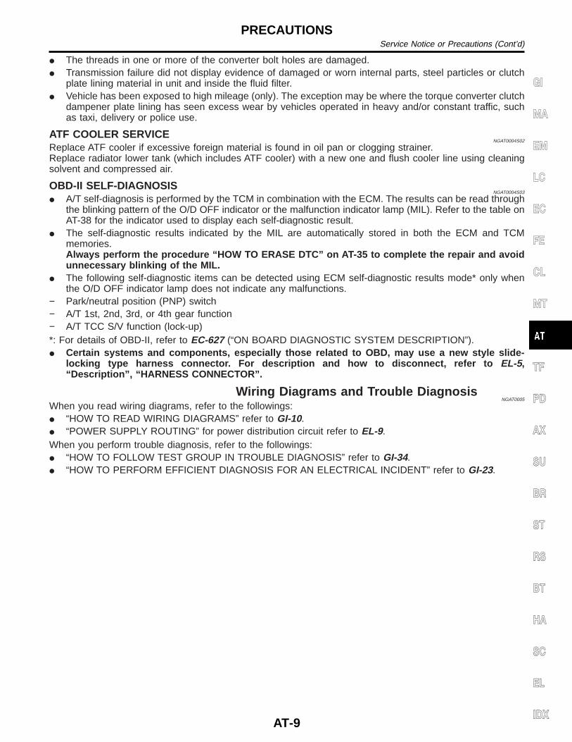
ATF COOLER SERVICENGAT0004S02
Replace ATF cooler if excessive foreign material is found in oil pan or clogging strainer.Replace radiator lower tank (which includes ATF cooler) with a new one and flush cooler line using cleaningsolvent and compressed air.
OBD-II SELF-DIAGNOSISNGAT0004S03
I A/T self-diagnosis is performed by the TCM in combination with the ECM. The results can be read throughthe blinking pattern of the O/D OFF indicator or the malfunction indicator lamp (MIL). Refer to the table onAT-38 for the indicator used to display each self-diagnostic result.
I The self-diagnostic results indicated by the MIL are automatically stored in both the ECM and TCMmemories.Always perform the procedure “HOW TO ERASE DTC” on AT-35 to complete the repair and avoidunnecessary blinking of the MIL.
I The following self-diagnostic items can be detected using ECM self-diagnostic results mode* only whenthe O/D OFF indicator lamp does not indicate any malfunctions.
− Park/neutral position (PNP) switch− A/T 1st, 2nd, 3rd, or 4th gear function− A/T TCC S/V function (lock-up)*: For details of OBD-II, refer to EC-627 (“ON BOARD DIAGNOSTIC SYSTEM DESCRIPTION”).I Certain systems and components, especially those related to OBD, may use a new style slide-
locking type harness connector. For description and how to disconnect, refer to EL-5,“Description”, “HARNESS CONNECTOR”.
Wiring Diagrams and Trouble DiagnosisNGAT0005
When you read wiring diagrams, refer to the followings:I “HOW TO READ WIRING DIAGRAMS” refer to GI-10.I “POWER SUPPLY ROUTING” for power distribution circuit refer to EL-9.When you perform trouble diagnosis, refer to the followings:I “HOW TO FOLLOW TEST GROUP IN TROUBLE DIAGNOSIS” refer to GI-34.I “HOW TO PERFORM EFFICIENT DIAGNOSIS FOR AN ELECTRICAL INCIDENT” refer to GI-23.
GI
MA
EM
LC
EC
FE
CL
MT
TF
PD
AX
SU
BR
ST
RS
BT
HA
SC
EL
IDX
PRECAUTIONSService Notice or Precautions (Cont’d)
AT-9
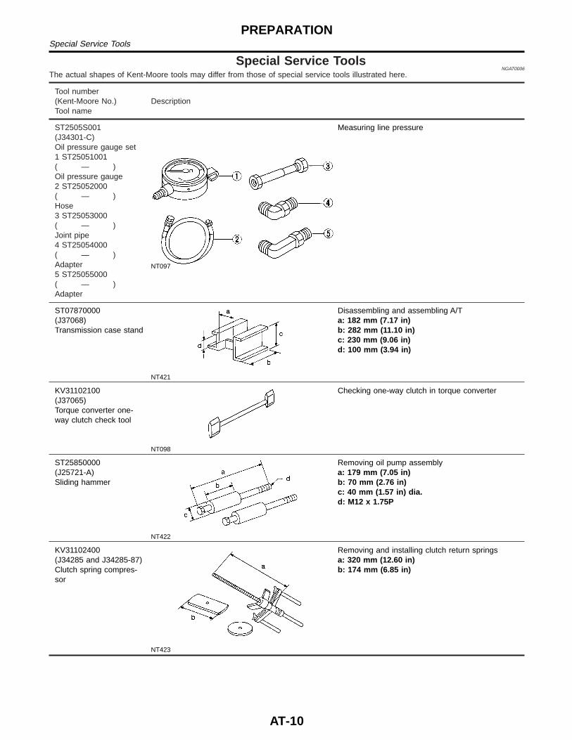
Special Service ToolsNGAT0006
The actual shapes of Kent-Moore tools may differ from those of special service tools illustrated here.
Tool number(Kent-Moore No.)Tool name
Description
ST2505S001(J34301-C)Oil pressure gauge set1 ST25051001( — )Oil pressure gauge2 ST25052000( — )Hose3 ST25053000( — )Joint pipe4 ST25054000( — )Adapter5 ST25055000( — )Adapter
NT097
Measuring line pressure
ST07870000(J37068)Transmission case stand
NT421
Disassembling and assembling A/Ta: 182 mm (7.17 in)b: 282 mm (11.10 in)c: 230 mm (9.06 in)d: 100 mm (3.94 in)
KV31102100(J37065)Torque converter one-way clutch check tool
NT098
Checking one-way clutch in torque converter
ST25850000(J25721-A)Sliding hammer
NT422
Removing oil pump assemblya: 179 mm (7.05 in)b: 70 mm (2.76 in)c: 40 mm (1.57 in) dia.d: M12 x 1.75P
KV31102400(J34285 and J34285-87)Clutch spring compres-sor
NT423
Removing and installing clutch return springsa: 320 mm (12.60 in)b: 174 mm (6.85 in)
PREPARATIONSpecial Service Tools
AT-10
Tool number(Kent-Moore No.)Tool name
Description
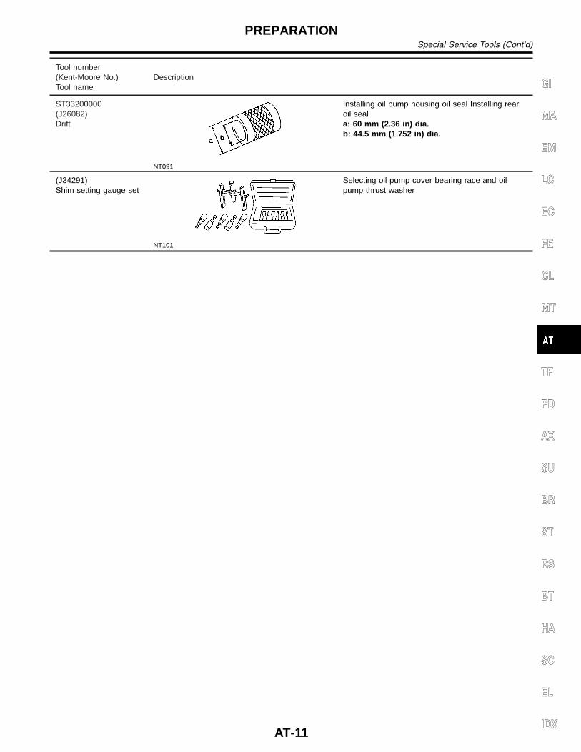
ST33200000(J26082)Drift
NT091
Installing oil pump housing oil seal Installing rearoil seala: 60 mm (2.36 in) dia.b: 44.5 mm (1.752 in) dia.
(J34291)Shim setting gauge set
NT101
Selecting oil pump cover bearing race and oilpump thrust washer
GI
MA
EM
LC
EC
FE
CL
MT
TF
PD
AX
SU
BR
ST
RS
BT
HA
SC
EL
IDX
PREPARATIONSpecial Service Tools (Cont’d)
AT-11
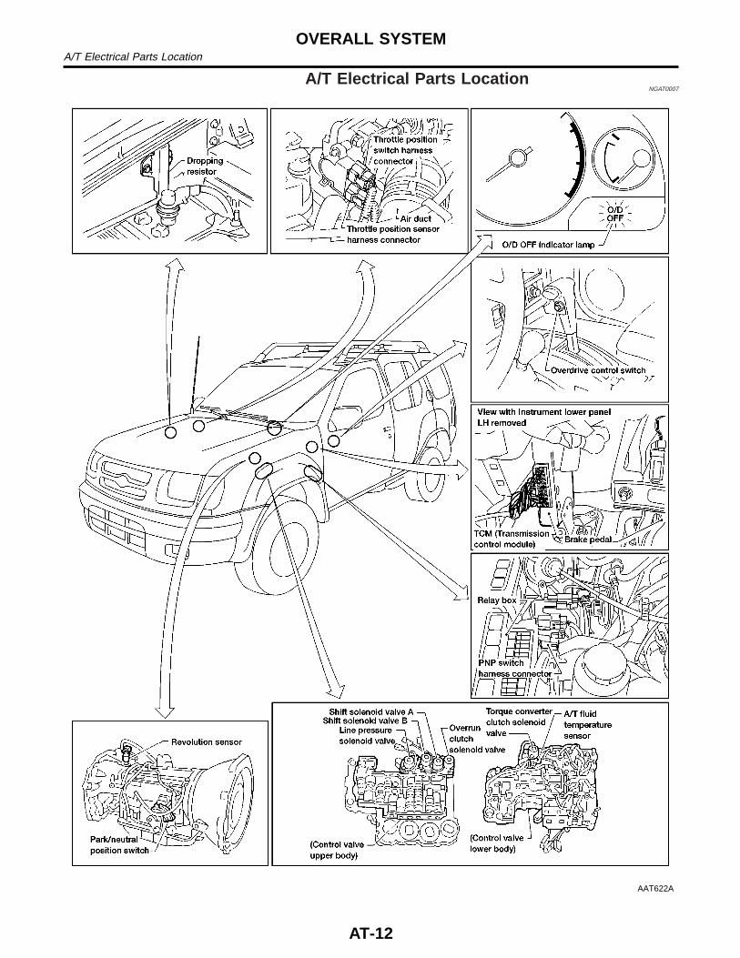
A/T Electrical Parts LocationNGAT0007
AAT622A
OVERALL SYSTEMA/T Electrical Parts Location
AT-12
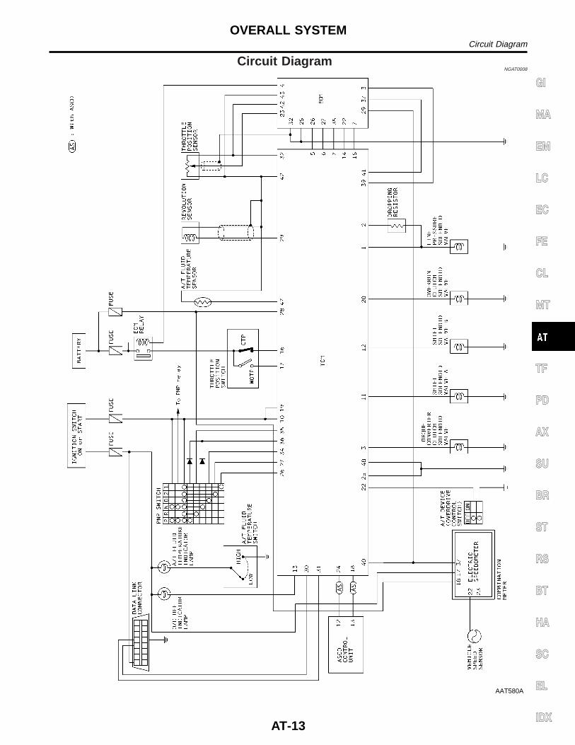
Circuit DiagramNGAT0008
AAT580A
GI
MA
EM
LC
EC
FE
CL
MT
TF
PD
AX
SU
BR
ST
RS
BT
HA
SC
EL
IDX
OVERALL SYSTEMCircuit Diagram
AT-13
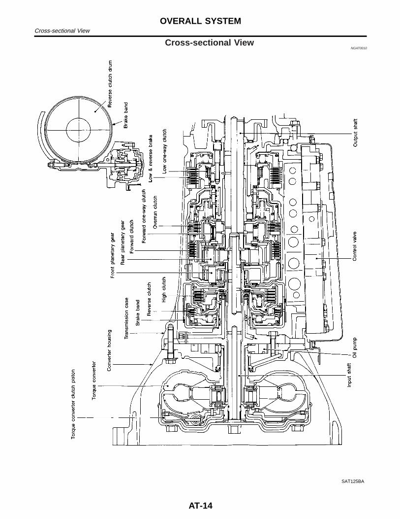
Cross-sectional ViewNGAT0010
SAT125BA
OVERALL SYSTEMCross-sectional View
AT-14
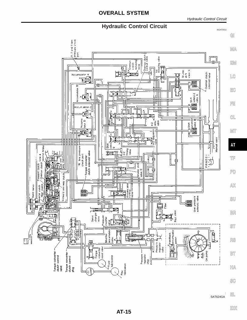
Hydraulic Control CircuitNGAT0011
SAT624GA
GI
MA
EM
LC
EC
FE
CL
MT
TF
PD
AX
SU
BR
ST
RS
BT
HA
SC
EL
IDX
OVERALL SYSTEMHydraulic Control Circuit
AT-15
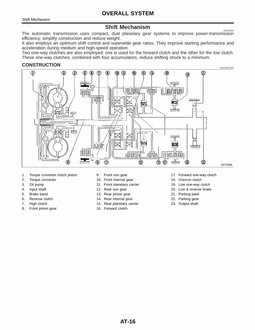
Shift MechanismNGAT0012
The automatic transmission uses compact, dual planetary gear systems to improve power-transmissionefficiency, simplify construction and reduce weight.It also employs an optimum shift control and superwide gear ratios. They improve starting performance andacceleration during medium and high-speed operation.Two one-way clutches are also employed: one is used for the forward clutch and the other for the low clutch.These one-way clutches, combined with four accumulators, reduce shifting shock to a minimum.
CONSTRUCTIONNGAT0012S01
SAT509I
1. Torque converter clutch piston2. Torque converter3. Oil pump4. Input shaft5. Brake band6. Reverse clutch7. High clutch8. Front pinion gear
9. Front sun gear10. Front internal gear11. Front planetary carrier12. Rear sun gear13. Rear pinion gear14. Rear internal gear15. Rear planetary carrier16. Forward clutch
17. Forward one-way clutch18. Overrun clutch19. Low one-way clutch20. Low & reverse brake21. Parking pawl22. Parking gear23. Output shaft
OVERALL SYSTEMShift Mechanism
AT-16
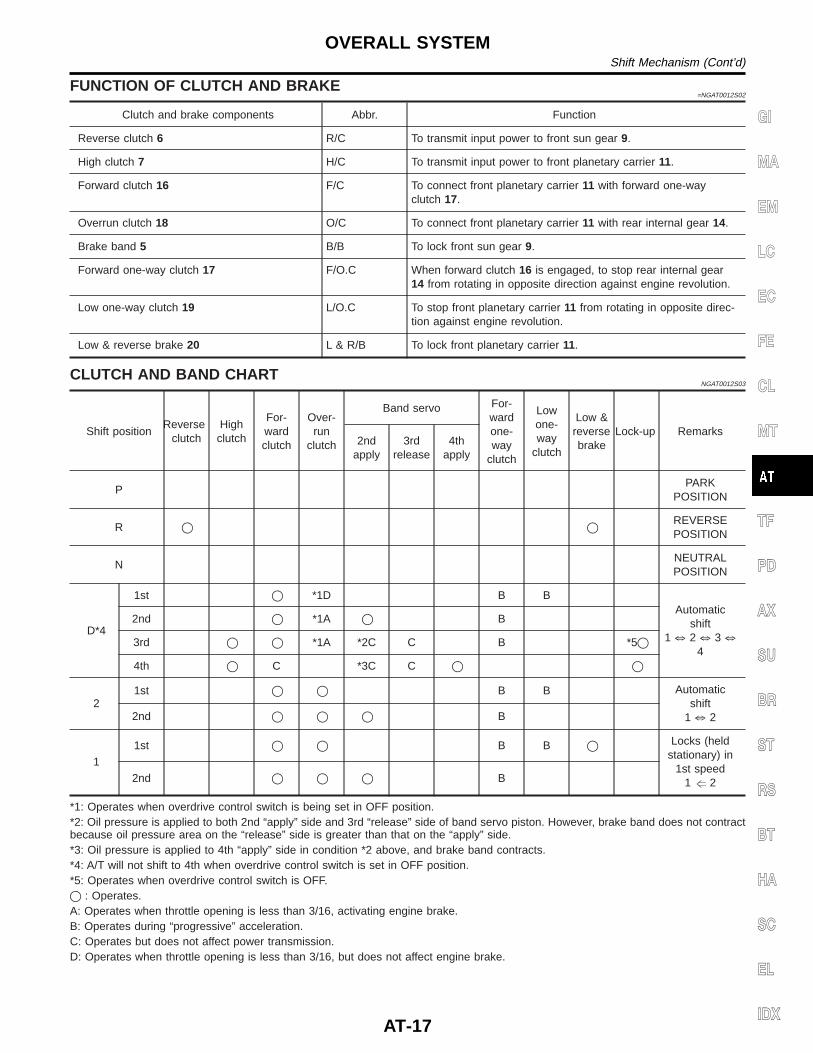
FUNCTION OF CLUTCH AND BRAKE=NGAT0012S02
Clutch and brake components Abbr. Function
Reverse clutch 6 R/C To transmit input power to front sun gear 9.
High clutch 7 H/C To transmit input power to front planetary carrier 11.
Forward clutch 16 F/C To connect front planetary carrier 11 with forward one-wayclutch 17.
Overrun clutch 18 O/C To connect front planetary carrier 11 with rear internal gear 14.
Brake band 5 B/B To lock front sun gear 9.
Forward one-way clutch 17 F/O.C When forward clutch 16 is engaged, to stop rear internal gear14 from rotating in opposite direction against engine revolution.
Low one-way clutch 19 L/O.C To stop front planetary carrier 11 from rotating in opposite direc-tion against engine revolution.
Low & reverse brake 20 L & R/B To lock front planetary carrier 11.
CLUTCH AND BAND CHARTNGAT0012S03
Shift positionReverse
clutchHigh
clutch
For-wardclutch
Over-run
clutch
Band servo For-wardone-way
clutch
Lowone-way
clutch
Low &reversebrake
Lock-up Remarks2nd
apply3rd
release4th
apply
PPARK
POSITION
R q q REVERSEPOSITION
NNEUTRALPOSITION
D*4
1st q *1D B BAutomatic
shift1 k 2 k 3 k
4
2nd q *1A q B
3rd q q *1A *2C C B *5q
4th q C *3C C q q
21st q q B B Automatic
shift1 k 22nd q q q B
1
1st q q B B q Locks (heldstationary) in
1st speed1 g 22nd q q q B
*1: Operates when overdrive control switch is being set in OFF position.*2: Oil pressure is applied to both 2nd “apply” side and 3rd “release” side of band servo piston. However, brake band does not contractbecause oil pressure area on the “release” side is greater than that on the “apply” side.*3: Oil pressure is applied to 4th “apply” side in condition *2 above, and brake band contracts.*4: A/T will not shift to 4th when overdrive control switch is set in OFF position.*5: Operates when overdrive control switch is OFF.q : Operates.A: Operates when throttle opening is less than 3/16, activating engine brake.B: Operates during “progressive” acceleration.C: Operates but does not affect power transmission.D: Operates when throttle opening is less than 3/16, but does not affect engine brake.
GI
MA
EM
LC
EC
FE
CL
MT
TF
PD
AX
SU
BR
ST
RS
BT
HA
SC
EL
IDX
OVERALL SYSTEMShift Mechanism (Cont’d)
AT-17
POWER TRANSMISSION=NGAT0012S04
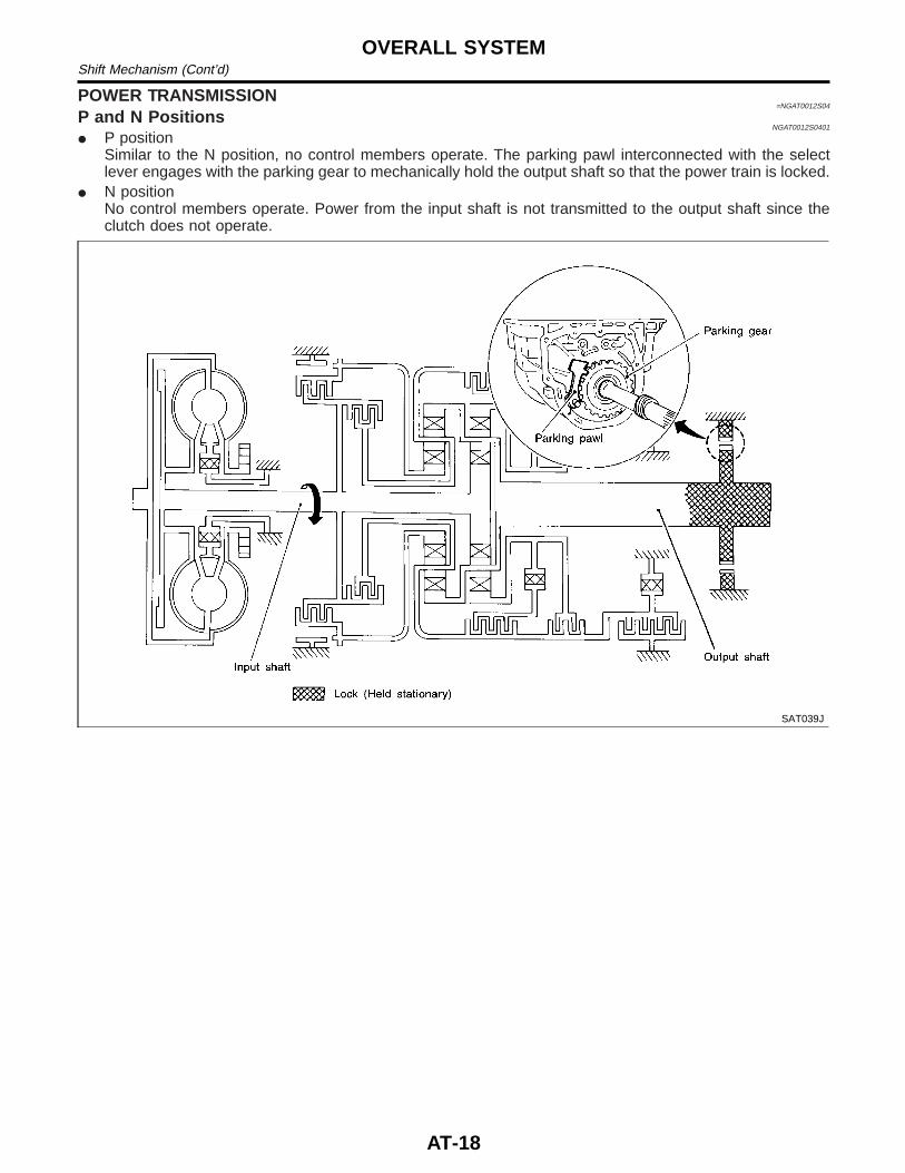
P and N PositionsNGAT0012S0401
I P positionSimilar to the N position, no control members operate. The parking pawl interconnected with the selectlever engages with the parking gear to mechanically hold the output shaft so that the power train is locked.
I N positionNo control members operate. Power from the input shaft is not transmitted to the output shaft since theclutch does not operate.
SAT039J
OVERALL SYSTEMShift Mechanism (Cont’d)
AT-18
11 Position=NGAT0012S0406
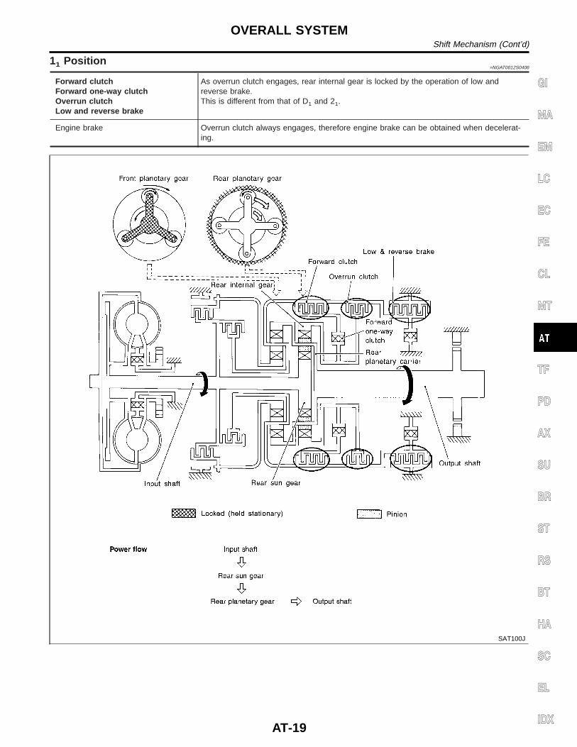
Forward clutchForward one-way clutchOverrun clutchLow and reverse brake
As overrun clutch engages, rear internal gear is locked by the operation of low andreverse brake.This is different from that of D1 and 21.
Engine brake Overrun clutch always engages, therefore engine brake can be obtained when decelerat-ing.
SAT100J
GI
MA
EM
LC
EC
FE
CL
MT
TF
PD
AX
SU
BR
ST
RS
BT
HA
SC
EL
IDX
OVERALL SYSTEMShift Mechanism (Cont’d)
AT-19
D1 and 21 Positions=NGAT0012S0402
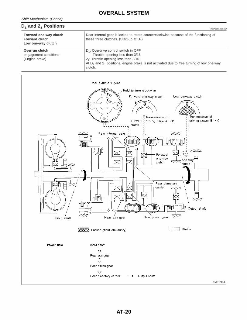
Forward one-way clutchForward clutchLow one-way clutch
Rear internal gear is locked to rotate counterclockwise because of the functioning ofthese three clutches. (Start-up at D1)
Overrun clutchengagement conditions(Engine brake)
D1: Overdrive control switch in OFFThrottle opening less than 3/16
21: Throttle opening less than 3/16At D1 and 21 positions, engine brake is not activated due to free turning of low one-wayclutch.
SAT096J
OVERALL SYSTEMShift Mechanism (Cont’d)
AT-20
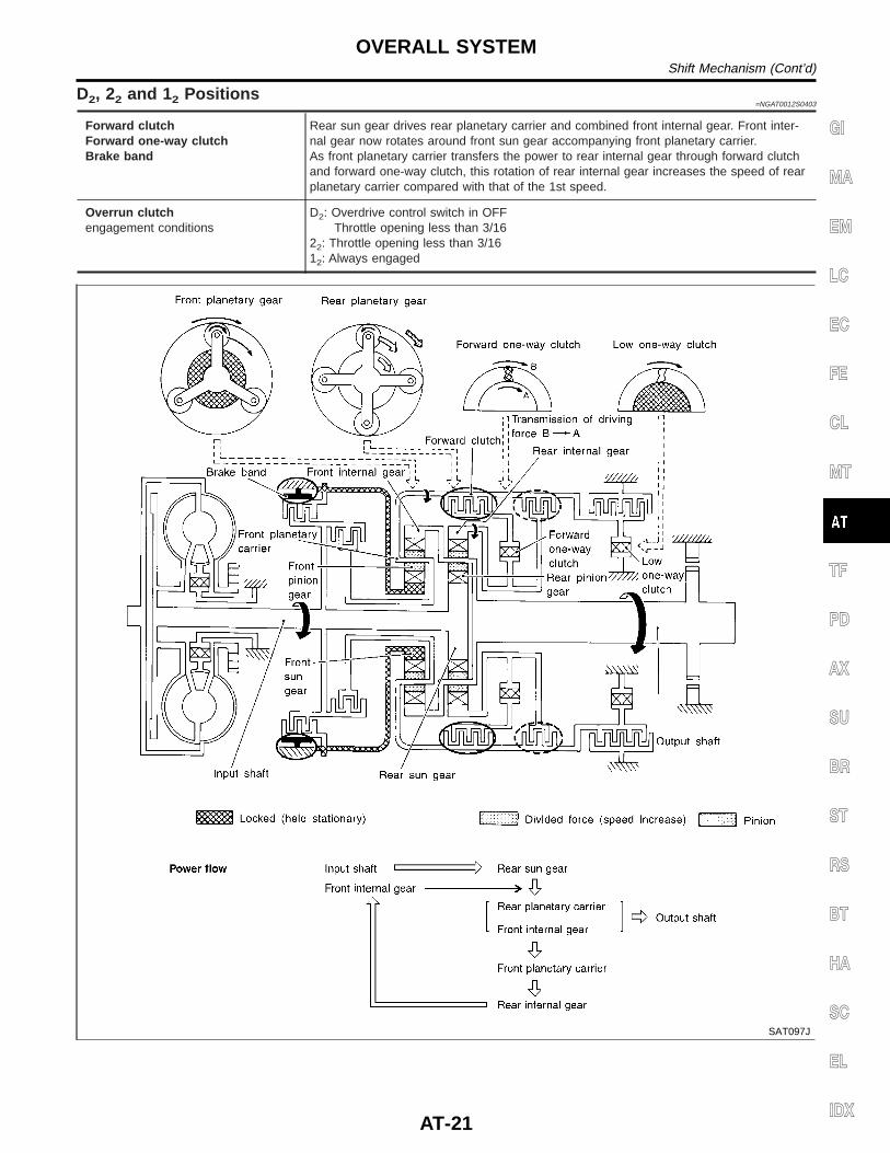
D2, 22 and 12 Positions=NGAT0012S0403
Forward clutchForward one-way clutchBrake band
Rear sun gear drives rear planetary carrier and combined front internal gear. Front inter-nal gear now rotates around front sun gear accompanying front planetary carrier.As front planetary carrier transfers the power to rear internal gear through forward clutchand forward one-way clutch, this rotation of rear internal gear increases the speed of rearplanetary carrier compared with that of the 1st speed.
Overrun clutchengagement conditions
D2: Overdrive control switch in OFFThrottle opening less than 3/16
22: Throttle opening less than 3/1612: Always engaged
SAT097J
GI
MA
EM
LC
EC
FE
CL
MT
TF
PD
AX
SU
BR
ST
RS
BT
HA
SC
EL
IDX
OVERALL SYSTEMShift Mechanism (Cont’d)
AT-21
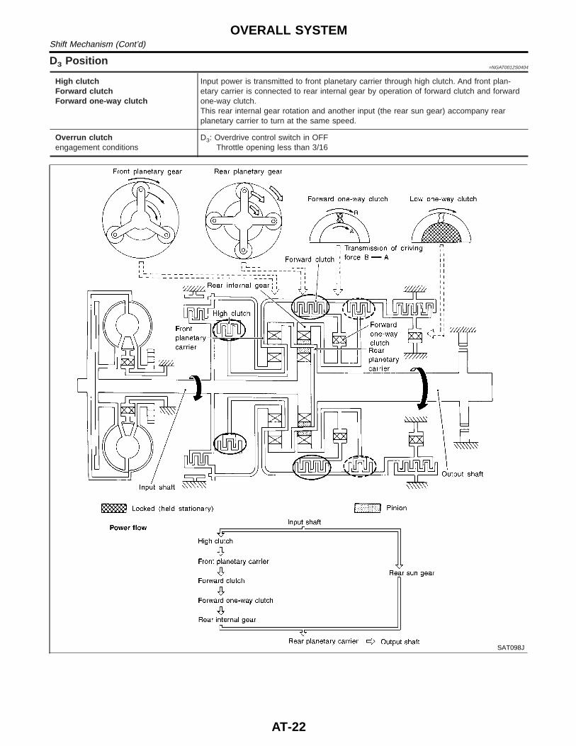
D3 Position=NGAT0012S0404
High clutchForward clutchForward one-way clutch
Input power is transmitted to front planetary carrier through high clutch. And front plan-etary carrier is connected to rear internal gear by operation of forward clutch and forwardone-way clutch.This rear internal gear rotation and another input (the rear sun gear) accompany rearplanetary carrier to turn at the same speed.
Overrun clutchengagement conditions
D3: Overdrive control switch in OFFThrottle opening less than 3/16
SAT098J
OVERALL SYSTEMShift Mechanism (Cont’d)
AT-22
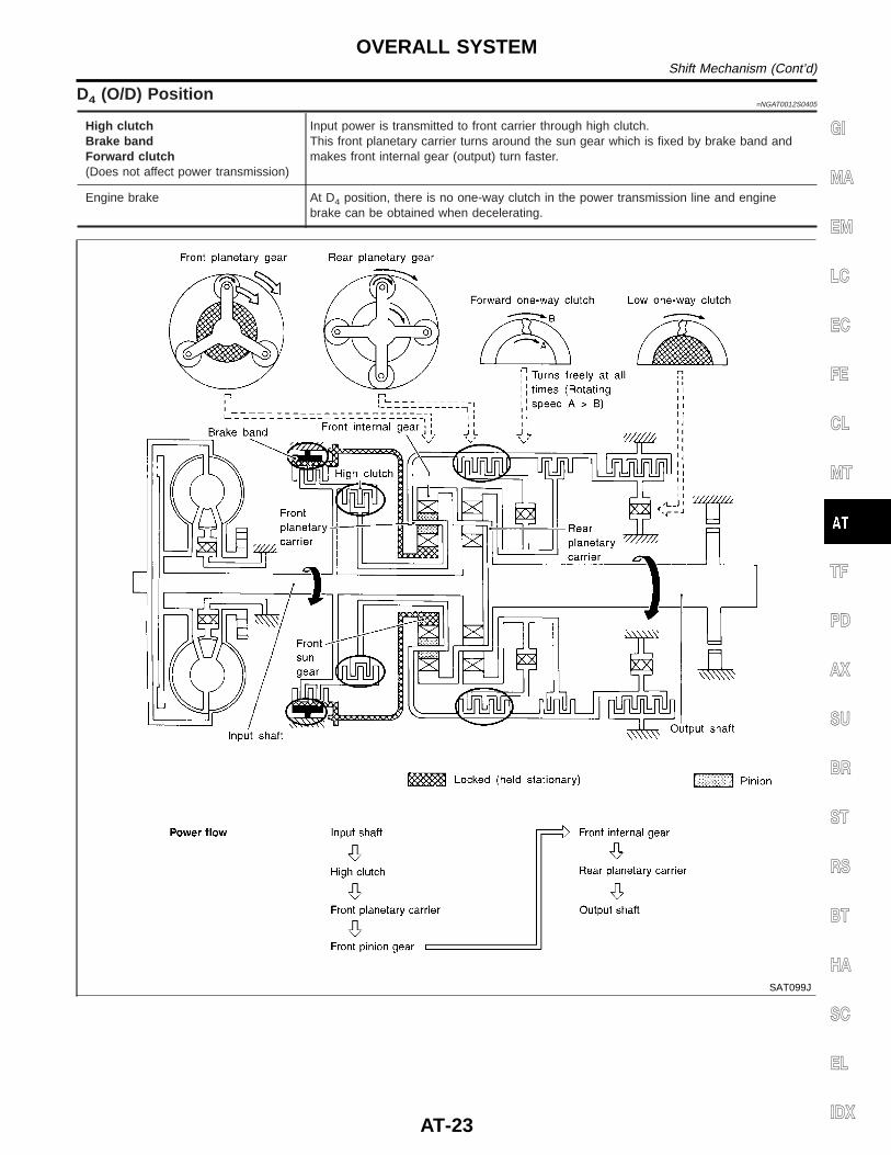
D4 (O/D) Position=NGAT0012S0405
High clutchBrake bandForward clutch(Does not affect power transmission)
Input power is transmitted to front carrier through high clutch.This front planetary carrier turns around the sun gear which is fixed by brake band andmakes front internal gear (output) turn faster.
Engine brake At D4 position, there is no one-way clutch in the power transmission line and enginebrake can be obtained when decelerating.
SAT099J
GI
MA
EM
LC
EC
FE
CL
MT
TF
PD
AX
SU
BR
ST
RS
BT
HA
SC
EL
IDX
OVERALL SYSTEMShift Mechanism (Cont’d)
AT-23
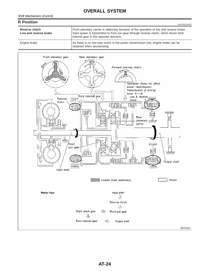
R Position=NGAT0012S0407
Reverse clutchLow and reverse brake
Front planetary carrier is stationary because of the operation of low and reverse brake.Input power is transmitted to front sun gear through reverse clutch, which drives frontinternal gear in the opposite direction.
Engine brake As there is no one-way clutch in the power transmission line, engine brake can beobtained when decelerating.
SAT101J
OVERALL SYSTEMShift Mechanism (Cont’d)
AT-24

Control System=NGAT0013
OUTLINENGAT0013S01
The automatic transmission senses vehicle operating conditions through various sensors. It always controlsthe optimum shift position and reduces shifting and lock-up shocks.
SENSORS
E
TCM
E
ACTUATORS
PNP switchThrottle position sensorClosed throttle position switchWide open throttle positionswitchEngine speed signalA/T fluid temperature sensorRevolution sensorVehicle speed sensorOverdrive control switchASCD control unit
Shift controlLine pressure controlLock-up controlOverrun clutch controlTiming controlFail-safe controlSelf-diagnosisCONSULT communication lineDuet-EU control
Shift solenoid valve AShift solenoid valve BOverrun clutch solenoid valveTorque converter clutch solenoidvalveLine pressure solenoid valveO/D OFF indicator lamp
CONTROL SYSTEMNGAT0013S02
AAT471A
GI
MA
EM
LC
EC
FE
CL
MT
TF
PD
AX
SU
BR
ST
RS
BT
HA
SC
EL
IDX
OVERALL SYSTEMControl System
AT-25
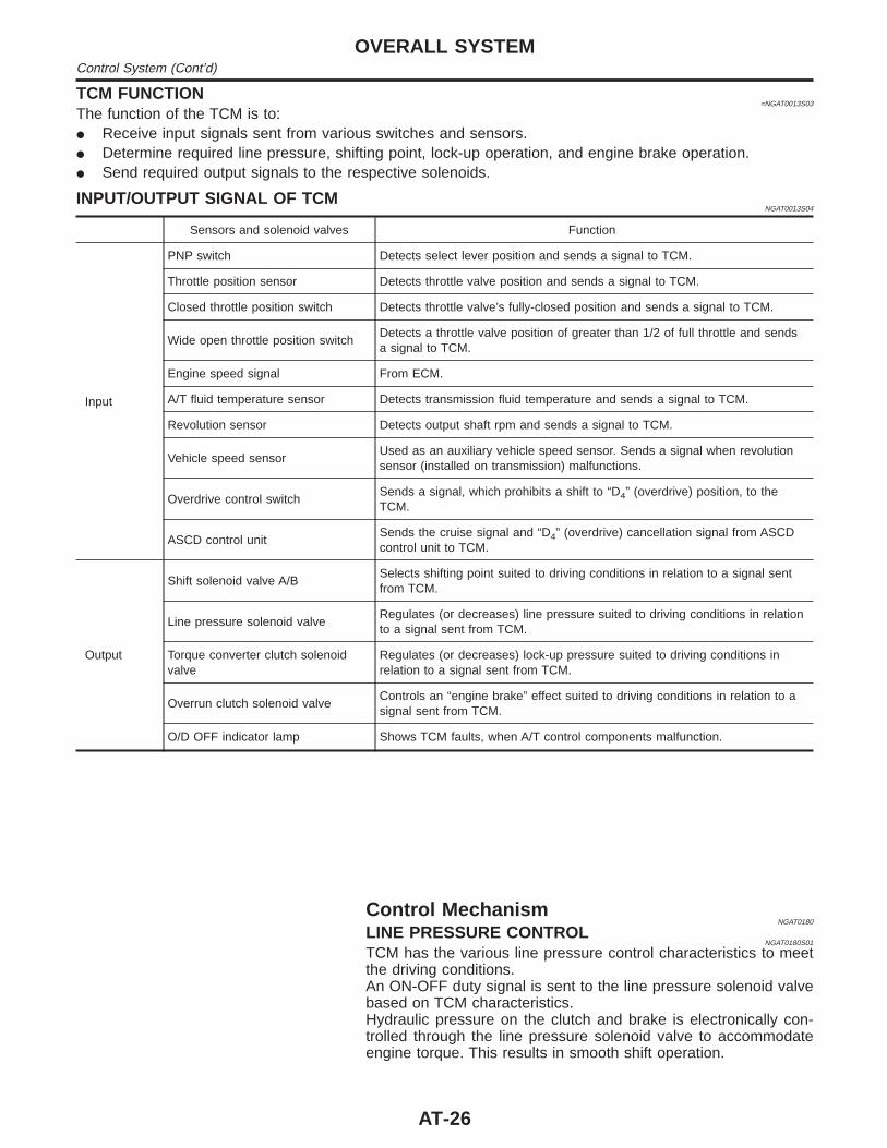
TCM FUNCTION=NGAT0013S03
The function of the TCM is to:I Receive input signals sent from various switches and sensors.I Determine required line pressure, shifting point, lock-up operation, and engine brake operation.I Send required output signals to the respective solenoids.
INPUT/OUTPUT SIGNAL OF TCMNGAT0013S04
Sensors and solenoid valves Function
Input
PNP switch Detects select lever position and sends a signal to TCM.
Throttle position sensor Detects throttle valve position and sends a signal to TCM.
Closed throttle position switch Detects throttle valve’s fully-closed position and sends a signal to TCM.
Wide open throttle position switchDetects a throttle valve position of greater than 1/2 of full throttle and sendsa signal to TCM.
Engine speed signal From ECM.
A/T fluid temperature sensor Detects transmission fluid temperature and sends a signal to TCM.
Revolution sensor Detects output shaft rpm and sends a signal to TCM.
Vehicle speed sensorUsed as an auxiliary vehicle speed sensor. Sends a signal when revolutionsensor (installed on transmission) malfunctions.
Overdrive control switchSends a signal, which prohibits a shift to “D4” (overdrive) position, to theTCM.
ASCD control unitSends the cruise signal and “D4” (overdrive) cancellation signal from ASCDcontrol unit to TCM.
Output
Shift solenoid valve A/BSelects shifting point suited to driving conditions in relation to a signal sentfrom TCM.
Line pressure solenoid valveRegulates (or decreases) line pressure suited to driving conditions in relationto a signal sent from TCM.
Torque converter clutch solenoidvalve
Regulates (or decreases) lock-up pressure suited to driving conditions inrelation to a signal sent from TCM.
Overrun clutch solenoid valveControls an “engine brake” effect suited to driving conditions in relation to asignal sent from TCM.
O/D OFF indicator lamp Shows TCM faults, when A/T control components malfunction.
Control MechanismNGAT0180
LINE PRESSURE CONTROLNGAT0180S01
TCM has the various line pressure control characteristics to meetthe driving conditions.An ON-OFF duty signal is sent to the line pressure solenoid valvebased on TCM characteristics.Hydraulic pressure on the clutch and brake is electronically con-trolled through the line pressure solenoid valve to accommodateengine torque. This results in smooth shift operation.
OVERALL SYSTEMControl System (Cont’d)
AT-26
SAT003J
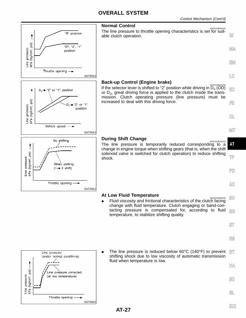
Normal ControlNGAT0180S0101
The line pressure to throttle opening characteristics is set for suit-able clutch operation.
SAT004J
Back-up Control (Engine brake)NGAT0180S0102
If the selector lever is shifted to “2” position while driving in D4 (OD)or D3, great driving force is applied to the clutch inside the trans-mission. Clutch operating pressure (line pressure) must beincreased to deal with this driving force.
SAT005J
During Shift ChangeNGAT0180S0103
The line pressure is temporarily reduced corresponding to achange in engine torque when shifting gears (that is, when the shiftsolenoid valve is switched for clutch operation) to reduce shiftingshock.
At Low Fluid TemperatureNGAT0180S0104
I Fluid viscosity and frictional characteristics of the clutch facingchange with fluid temperature. Clutch engaging or band-con-tacting pressure is compensated for, according to fluidtemperature, to stabilize shifting quality.
SAT006J
I The line pressure is reduced below 60°C (140°F) to preventshifting shock due to low viscosity of automatic transmissionfluid when temperature is low.
GI
MA
EM
LC
EC
FE
CL
MT
TF
PD
AX
SU
BR
ST
RS
BT
HA
SC
EL
IDX
OVERALL SYSTEMControl Mechanism (Cont’d)
AT-27
SAT007J
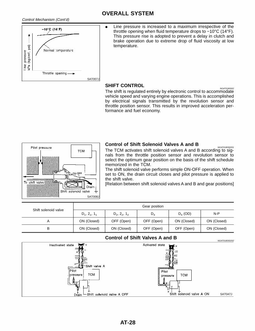
I Line pressure is increased to a maximum irrespective of thethrottle opening when fluid temperature drops to −10°C (14°F).This pressure rise is adopted to prevent a delay in clutch andbrake operation due to extreme drop of fluid viscosity at lowtemperature.
SHIFT CONTROLNGAT0180S02
The shift is regulated entirely by electronic control to accommodatevehicle speed and varying engine operations. This is accomplishedby electrical signals transmitted by the revolution sensor andthrottle position sensor. This results in improved acceleration per-formance and fuel economy.
SAT008J
Control of Shift Solenoid Valves A and BNGAT0180S0201
The TCM activates shift solenoid valves A and B according to sig-nals from the throttle position sensor and revolution sensor toselect the optimum gear position on the basis of the shift schedulememorized in the TCM.The shift solenoid valve performs simple ON-OFF operation. Whenset to ON, the drain circuit closes and pilot pressure is applied tothe shift valve.[Relation between shift solenoid valves A and B and gear positions]
Shift solenoid valveGear position
D1, 21, 11 D2, 22, 12 D3 D4 (OD) N-P
A ON (Closed) OFF (Open) OFF (Open) ON (Closed) ON (Closed)
B ON (Closed) ON (Closed) OFF (Open) OFF (Open) ON (Closed)
Control of Shift Valves A and BNGAT0180S0202
SAT047J
OVERALL SYSTEMControl Mechanism (Cont’d)
AT-28
Pilot pressure generated by the operation of shift solenoid valvesA and B is applied to the end face of shift valves A and B.The drawing above shows the operation of shift valve B. When theshift solenoid valve is “ON”, pilot pressure applied to the end faceof the shift valve overcomes spring force, moving the valve upward.
LOCK-UP CONTROLNGAT0180S03
The torque converter clutch piston in the torque converter is lockedto eliminate torque converter slip to increase power transmissionefficiency. The solenoid valve is controlled by an ON-OFF dutysignal sent from the TCM. The signal is converted to oil pressuresignal which controls the torque converter clutch piston.
Conditions for Lock-up OperationNGAT0180S0301
When vehicle is driven in 4th gear position, vehicle speed andthrottle opening are detected. If the detected values fall within thelock-up zone memorized in the TCM, lock-up is performed.
Overdrive control switch ON OFF
Selector lever “D” position
Gear position D4 D3
Vehicle speed sensor More than set value
Throttle position sensor Less than set opening
Closed throttle position switch OFF
A/T fluid temperature sensor More than 40°C (104°F)
SAT010J
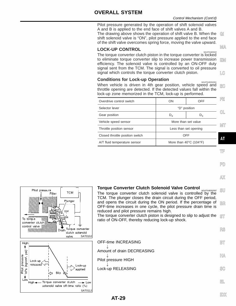
Torque Converter Clutch Solenoid Valve ControlNGAT0180S0302
The torque converter clutch solenoid valve is controlled by theTCM. The plunger closes the drain circuit during the OFF period,and opens the circuit during the ON period. If the percentage ofOFF-time increases in one cycle, the pilot pressure drain time isreduced and pilot pressure remains high.The torque converter clutch piston is designed to slip to adjust theratio of ON-OFF, thereby reducing lock-up shock.
SAT011J
OFF-time INCREASING"
Amount of drain DECREASING"
Pilot pressure HIGH"
Lock-up RELEASING
GI
MA
EM
LC
EC
FE
CL
MT
TF
PD
AX
SU
BR
ST
RS
BT
HA
SC
EL
IDX
OVERALL SYSTEMControl Mechanism (Cont’d)
AT-29
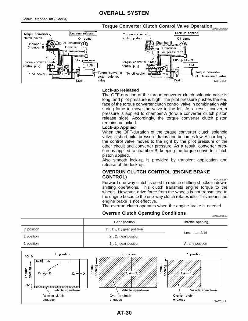
Torque Converter Clutch Control Valve OperationNGAT0180S0303
SAT048J
Lock-up ReleasedThe OFF-duration of the torque converter clutch solenoid valve islong, and pilot pressure is high. The pilot pressure pushes the endface of the torque converter clutch control valve in combination withspring force to move the valve to the left. As a result, converterpressure is applied to chamber A (torque converter clutch pistonrelease side). Accordingly, the torque converter clutch pistonremains unlocked.Lock-up AppliedWhen the OFF-duration of the torque converter clutch solenoidvalve is short, pilot pressure drains and becomes low. Accordingly,the control valve moves to the right by the pilot pressure of theother circuit and converter pressure. As a result, converter pres-sure is applied to chamber B, keeping the torque converter clutchpiston applied.Also smooth lock-up is provided by transient application andrelease of the lock-up.
OVERRUN CLUTCH CONTROL (ENGINE BRAKECONTROL)
NGAT0180S04
Forward one-way clutch is used to reduce shifting shocks in down-shifting operations. This clutch transmits engine torque to thewheels. However, drive force from the wheels is not transmitted tothe engine because the one-way clutch rotates idle. This means theengine brake is not effective.The overrun clutch operates when the engine brake is needed.
Overrun Clutch Operating ConditionsNGAT0180S0401
Gear position Throttle opening
D position D1, D2, D3 gear positionLess than 3/16
2 position 21, 22 gear position
1 position 11, 12 gear position At any position
SAT014J
OVERALL SYSTEMControl Mechanism (Cont’d)
AT-30
SAT015J
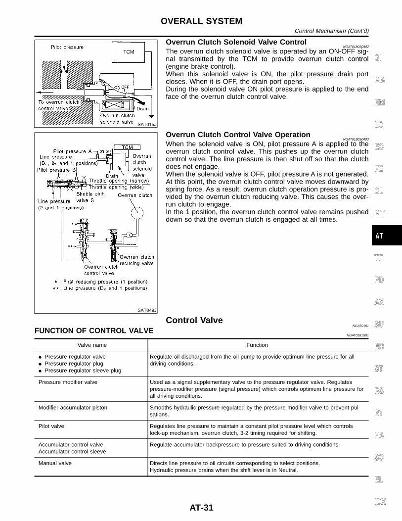
Overrun Clutch Solenoid Valve ControlNGAT0180S0402
The overrun clutch solenoid valve is operated by an ON-OFF sig-nal transmitted by the TCM to provide overrun clutch control(engine brake control).When this solenoid valve is ON, the pilot pressure drain portcloses. When it is OFF, the drain port opens.During the solenoid valve ON pilot pressure is applied to the endface of the overrun clutch control valve.
SAT049J
Overrun Clutch Control Valve OperationNGAT0180S0403
When the solenoid valve is ON, pilot pressure A is applied to theoverrun clutch control valve. This pushes up the overrun clutchcontrol valve. The line pressure is then shut off so that the clutchdoes not engage.When the solenoid valve is OFF, pilot pressure A is not generated.At this point, the overrun clutch control valve moves downward byspring force. As a result, overrun clutch operation pressure is pro-vided by the overrun clutch reducing valve. This causes the over-run clutch to engage.In the 1 position, the overrun clutch control valve remains pusheddown so that the overrun clutch is engaged at all times.
Control ValveNGAT0181
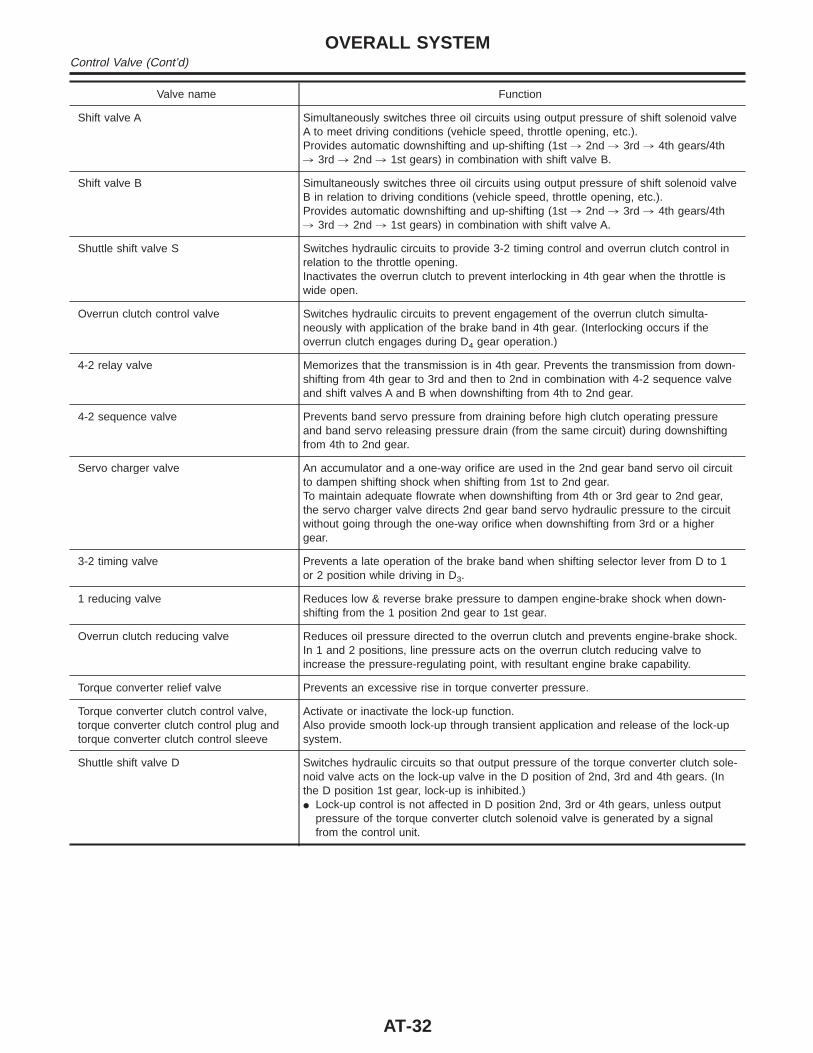
FUNCTION OF CONTROL VALVENGAT0181S01
Valve name Function
I Pressure regulator valveI Pressure regulator plugI Pressure regulator sleeve plug
Regulate oil discharged from the oil pump to provide optimum line pressure for alldriving conditions.
Pressure modifier valve Used as a signal supplementary valve to the pressure regulator valve. Regulatespressure-modifier pressure (signal pressure) which controls optimum line pressure forall driving conditions.
Modifier accumulator piston Smooths hydraulic pressure regulated by the pressure modifier valve to prevent pul-sations.
Pilot valve Regulates line pressure to maintain a constant pilot pressure level which controlslock-up mechanism, overrun clutch, 3-2 timing required for shifting.
Accumulator control valveAccumulator control sleeve
Regulate accumulator backpressure to pressure suited to driving conditions.
Manual valve Directs line pressure to oil circuits corresponding to select positions.Hydraulic pressure drains when the shift lever is in Neutral.
GI
MA
EM
LC
EC
FE
CL
MT
TF
PD
AX
SU
BR
ST
RS
BT
HA
SC
EL
IDX
OVERALL SYSTEMControl Mechanism (Cont’d)
AT-31
Valve name Function
Shift valve A Simultaneously switches three oil circuits using output pressure of shift solenoid valveA to meet driving conditions (vehicle speed, throttle opening, etc.).Provides automatic downshifting and up-shifting (1st , 2nd , 3rd , 4th gears/4th, 3rd , 2nd , 1st gears) in combination with shift valve B.
Shift valve B Simultaneously switches three oil circuits using output pressure of shift solenoid valveB in relation to driving conditions (vehicle speed, throttle opening, etc.).Provides automatic downshifting and up-shifting (1st , 2nd , 3rd , 4th gears/4th, 3rd , 2nd , 1st gears) in combination with shift valve A.
Shuttle shift valve S Switches hydraulic circuits to provide 3-2 timing control and overrun clutch control inrelation to the throttle opening.Inactivates the overrun clutch to prevent interlocking in 4th gear when the throttle iswide open.
Overrun clutch control valve Switches hydraulic circuits to prevent engagement of the overrun clutch simulta-neously with application of the brake band in 4th gear. (Interlocking occurs if theoverrun clutch engages during D4 gear operation.)
4-2 relay valve Memorizes that the transmission is in 4th gear. Prevents the transmission from down-shifting from 4th gear to 3rd and then to 2nd in combination with 4-2 sequence valveand shift valves A and B when downshifting from 4th to 2nd gear.
4-2 sequence valve Prevents band servo pressure from draining before high clutch operating pressureand band servo releasing pressure drain (from the same circuit) during downshiftingfrom 4th to 2nd gear.
Servo charger valve An accumulator and a one-way orifice are used in the 2nd gear band servo oil circuitto dampen shifting shock when shifting from 1st to 2nd gear.To maintain adequate flowrate when downshifting from 4th or 3rd gear to 2nd gear,the servo charger valve directs 2nd gear band servo hydraulic pressure to the circuitwithout going through the one-way orifice when downshifting from 3rd or a highergear.
3-2 timing valve Prevents a late operation of the brake band when shifting selector lever from D to 1or 2 position while driving in D3.
1 reducing valve Reduces low & reverse brake pressure to dampen engine-brake shock when down-shifting from the 1 position 2nd gear to 1st gear.
Overrun clutch reducing valve Reduces oil pressure directed to the overrun clutch and prevents engine-brake shock.In 1 and 2 positions, line pressure acts on the overrun clutch reducing valve toincrease the pressure-regulating point, with resultant engine brake capability.
Torque converter relief valve Prevents an excessive rise in torque converter pressure.
Torque converter clutch control valve,torque converter clutch control plug andtorque converter clutch control sleeve
Activate or inactivate the lock-up function.Also provide smooth lock-up through transient application and release of the lock-upsystem.
Shuttle shift valve D Switches hydraulic circuits so that output pressure of the torque converter clutch sole-noid valve acts on the lock-up valve in the D position of 2nd, 3rd and 4th gears. (Inthe D position 1st gear, lock-up is inhibited.)I Lock-up control is not affected in D position 2nd, 3rd or 4th gears, unless output
pressure of the torque converter clutch solenoid valve is generated by a signalfrom the control unit.
OVERALL SYSTEMControl Valve (Cont’d)
AT-32
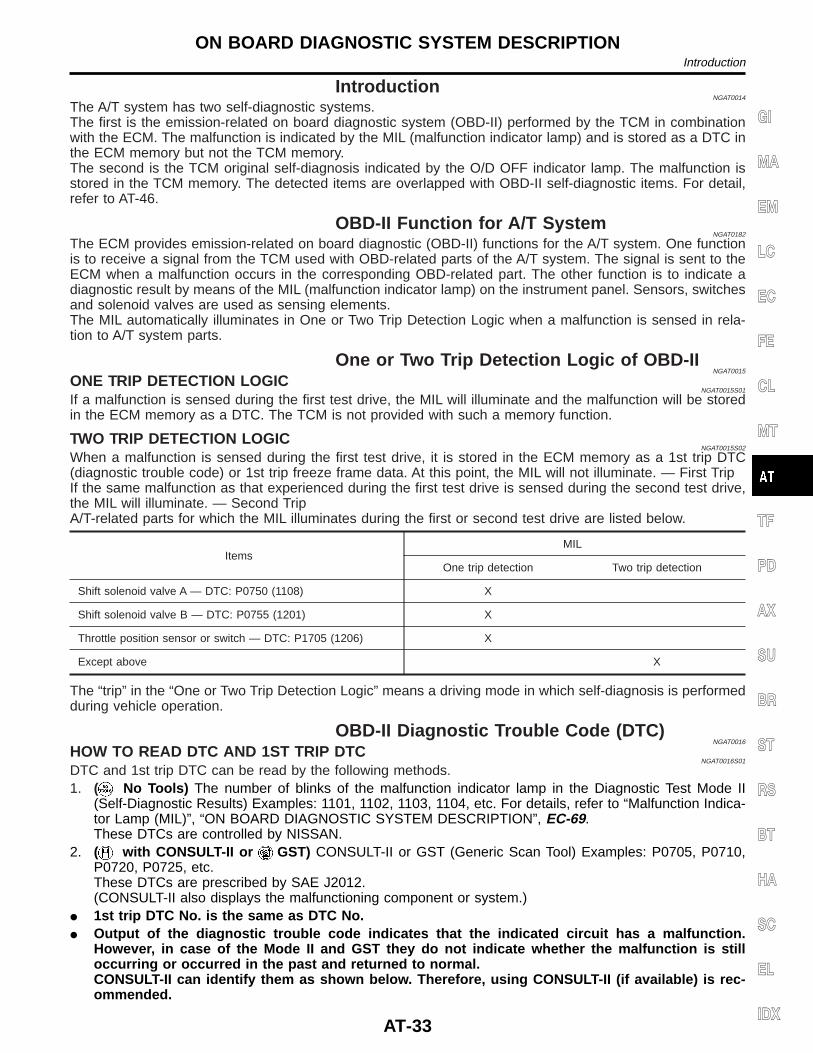
IntroductionNGAT0014
The A/T system has two self-diagnostic systems.The first is the emission-related on board diagnostic system (OBD-II) performed by the TCM in combinationwith the ECM. The malfunction is indicated by the MIL (malfunction indicator lamp) and is stored as a DTC inthe ECM memory but not the TCM memory.The second is the TCM original self-diagnosis indicated by the O/D OFF indicator lamp. The malfunction isstored in the TCM memory. The detected items are overlapped with OBD-II self-diagnostic items. For detail,refer to AT-46.
OBD-II Function for A/T SystemNGAT0182
The ECM provides emission-related on board diagnostic (OBD-II) functions for the A/T system. One functionis to receive a signal from the TCM used with OBD-related parts of the A/T system. The signal is sent to theECM when a malfunction occurs in the corresponding OBD-related part. The other function is to indicate adiagnostic result by means of the MIL (malfunction indicator lamp) on the instrument panel. Sensors, switchesand solenoid valves are used as sensing elements.The MIL automatically illuminates in One or Two Trip Detection Logic when a malfunction is sensed in rela-tion to A/T system parts.
One or Two Trip Detection Logic of OBD-IINGAT0015
ONE TRIP DETECTION LOGICNGAT0015S01
If a malfunction is sensed during the first test drive, the MIL will illuminate and the malfunction will be storedin the ECM memory as a DTC. The TCM is not provided with such a memory function.
TWO TRIP DETECTION LOGICNGAT0015S02
When a malfunction is sensed during the first test drive, it is stored in the ECM memory as a 1st trip DTC(diagnostic trouble code) or 1st trip freeze frame data. At this point, the MIL will not illuminate. — First TripIf the same malfunction as that experienced during the first test drive is sensed during the second test drive,the MIL will illuminate. — Second TripA/T-related parts for which the MIL illuminates during the first or second test drive are listed below.
ItemsMIL
One trip detection Two trip detection
Shift solenoid valve A — DTC: P0750 (1108) X
Shift solenoid valve B — DTC: P0755 (1201) X
Throttle position sensor or switch — DTC: P1705 (1206) X
Except above X
The “trip” in the “One or Two Trip Detection Logic” means a driving mode in which self-diagnosis is performedduring vehicle operation.
OBD-II Diagnostic Trouble Code (DTC)NGAT0016
HOW TO READ DTC AND 1ST TRIP DTCNGAT0016S01
DTC and 1st trip DTC can be read by the following methods.1. ( No Tools) The number of blinks of the malfunction indicator lamp in the Diagnostic Test Mode II
(Self-Diagnostic Results) Examples: 1101, 1102, 1103, 1104, etc. For details, refer to “Malfunction Indica-tor Lamp (MIL)”, “ON BOARD DIAGNOSTIC SYSTEM DESCRIPTION”, EC-69.These DTCs are controlled by NISSAN.
2. ( with CONSULT-II or GST) CONSULT-II or GST (Generic Scan Tool) Examples: P0705, P0710,P0720, P0725, etc.These DTCs are prescribed by SAE J2012.(CONSULT-II also displays the malfunctioning component or system.)
I 1st trip DTC No. is the same as DTC No.I Output of the diagnostic trouble code indicates that the indicated circuit has a malfunction.
However, in case of the Mode II and GST they do not indicate whether the malfunction is stilloccurring or occurred in the past and returned to normal.CONSULT-II can identify them as shown below. Therefore, using CONSULT-II (if available) is rec-ommended.
GI
MA
EM
LC
EC
FE
CL
MT
TF
PD
AX
SU
BR
ST
RS
BT
HA
SC
EL
IDX
ON BOARD DIAGNOSTIC SYSTEM DESCRIPTIONIntroduction
AT-33
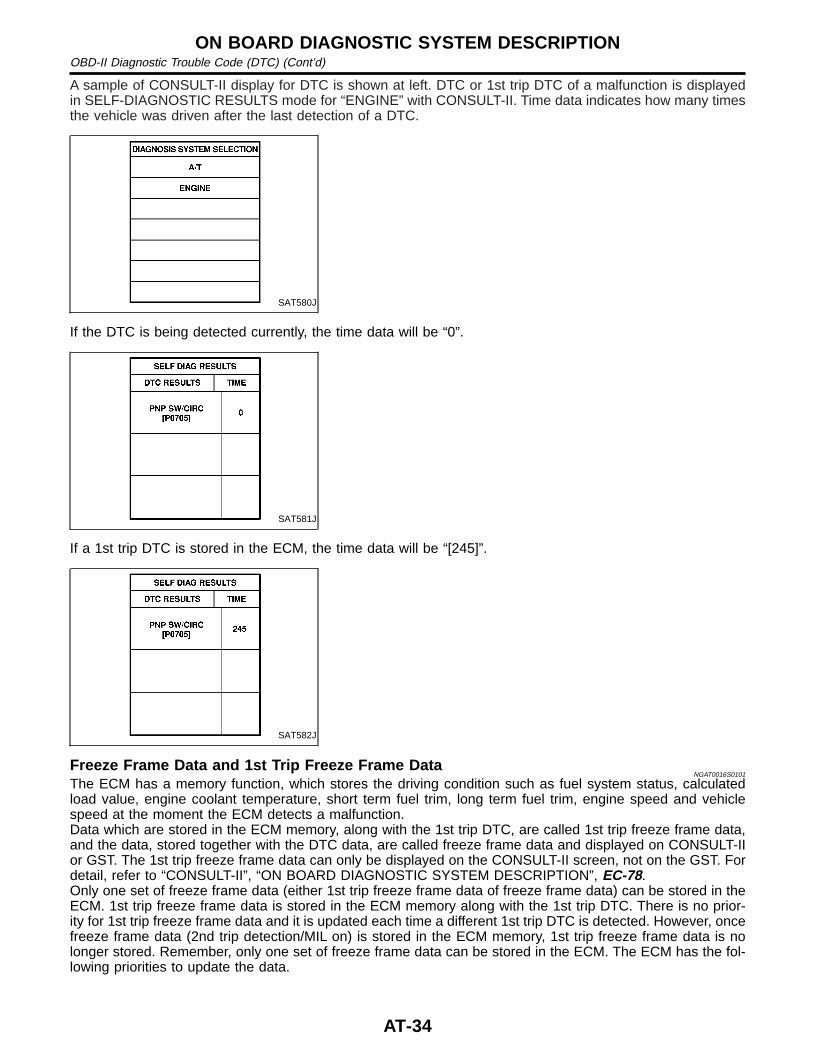
A sample of CONSULT-II display for DTC is shown at left. DTC or 1st trip DTC of a malfunction is displayedin SELF-DIAGNOSTIC RESULTS mode for “ENGINE” with CONSULT-II. Time data indicates how many timesthe vehicle was driven after the last detection of a DTC.
SAT580J
If the DTC is being detected currently, the time data will be “0”.
SAT581J
If a 1st trip DTC is stored in the ECM, the time data will be “[245]”.
SAT582J
Freeze Frame Data and 1st Trip Freeze Frame DataNGAT0016S0101
The ECM has a memory function, which stores the driving condition such as fuel system status, calculatedload value, engine coolant temperature, short term fuel trim, long term fuel trim, engine speed and vehiclespeed at the moment the ECM detects a malfunction.Data which are stored in the ECM memory, along with the 1st trip DTC, are called 1st trip freeze frame data,and the data, stored together with the DTC data, are called freeze frame data and displayed on CONSULT-IIor GST. The 1st trip freeze frame data can only be displayed on the CONSULT-II screen, not on the GST. Fordetail, refer to “CONSULT-II”, “ON BOARD DIAGNOSTIC SYSTEM DESCRIPTION”, EC-78.Only one set of freeze frame data (either 1st trip freeze frame data of freeze frame data) can be stored in theECM. 1st trip freeze frame data is stored in the ECM memory along with the 1st trip DTC. There is no prior-ity for 1st trip freeze frame data and it is updated each time a different 1st trip DTC is detected. However, oncefreeze frame data (2nd trip detection/MIL on) is stored in the ECM memory, 1st trip freeze frame data is nolonger stored. Remember, only one set of freeze frame data can be stored in the ECM. The ECM has the fol-lowing priorities to update the data.
ON BOARD DIAGNOSTIC SYSTEM DESCRIPTIONOBD-II Diagnostic Trouble Code (DTC) (Cont’d)
AT-34
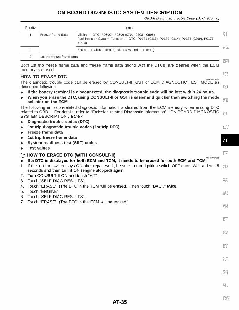
Priority Items
1 Freeze frame data Misfire — DTC: P0300 - P0306 (0701, 0603 - 0608)Fuel Injection System Function — DTC: P0171 (0115), P0172 (0114), P0174 (0209), P0175(0210)
2 Except the above items (Includes A/T related items)
3 1st trip freeze frame data
Both 1st trip freeze frame data and freeze frame data (along with the DTCs) are cleared when the ECMmemory is erased.
HOW TO ERASE DTCNGAT0016S02
The diagnostic trouble code can be erased by CONSULT-II, GST or ECM DIAGNOSTIC TEST MODE asdescribed following.I If the battery terminal is disconnected, the diagnostic trouble code will be lost within 24 hours.I When you erase the DTC, using CONSULT-II or GST is easier and quicker than switching the mode
selector on the ECM.The following emission-related diagnostic information is cleared from the ECM memory when erasing DTCrelated to OBD-II. For details, refer to “Emission-related Diagnostic Information”, “ON BOARD DIAGNOSTICSYSTEM DESCRIPTION”, EC-57.I Diagnostic trouble codes (DTC)I 1st trip diagnostic trouble codes (1st trip DTC)I Freeze frame dataI 1st trip freeze frame dataI System readiness test (SRT) codesI Test values
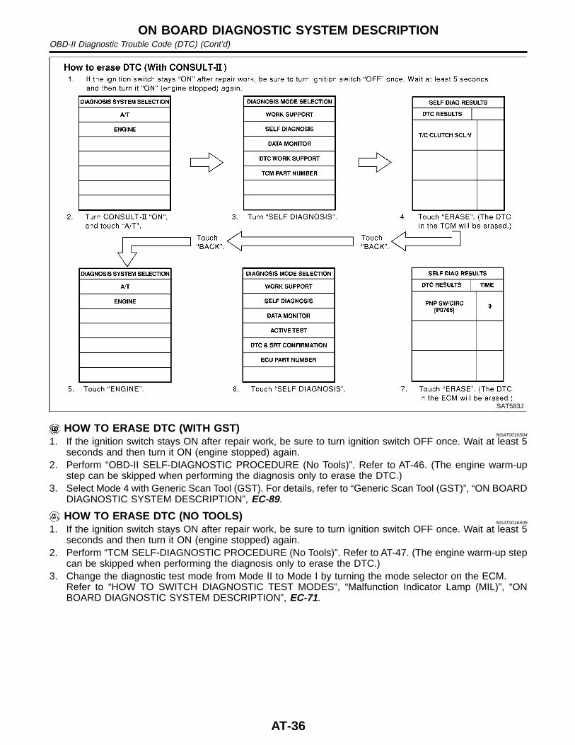
HOW TO ERASE DTC (WITH CONSULT-II)NGAT0016S03
I If a DTC is displayed for both ECM and TCM, it needs to be erased for both ECM and TCM.1. If the ignition switch stays ON after repair work, be sure to turn ignition switch OFF once. Wait at least 5
seconds and then turn it ON (engine stopped) again.2. Turn CONSULT-II ON and touch “A/T”.3. Touch “SELF-DIAG RESULTS”.4. Touch “ERASE”. (The DTC in the TCM will be erased.) Then touch “BACK” twice.5. Touch “ENGINE”.6. Touch “SELF-DIAG RESULTS”.7. Touch “ERASE”. (The DTC in the ECM will be erased.)
GI
MA
EM
LC
EC
FE
CL
MT
TF
PD
AX
SU
BR
ST
RS
BT
HA
SC
EL
IDX
ON BOARD DIAGNOSTIC SYSTEM DESCRIPTIONOBD-II Diagnostic Trouble Code (DTC) (Cont’d)
AT-35
SAT583J
HOW TO ERASE DTC (WITH GST)NGAT0016S04
1. If the ignition switch stays ON after repair work, be sure to turn ignition switch OFF once. Wait at least 5seconds and then turn it ON (engine stopped) again.
2. Perform “OBD-II SELF-DIAGNOSTIC PROCEDURE (No Tools)”. Refer to AT-46. (The engine warm-upstep can be skipped when performing the diagnosis only to erase the DTC.)
3. Select Mode 4 with Generic Scan Tool (GST). For details, refer to “Generic Scan Tool (GST)”, “ON BOARDDIAGNOSTIC SYSTEM DESCRIPTION”, EC-89.
HOW TO ERASE DTC (NO TOOLS)NGAT0016S05
1. If the ignition switch stays ON after repair work, be sure to turn ignition switch OFF once. Wait at least 5seconds and then turn it ON (engine stopped) again.
2. Perform “TCM SELF-DIAGNOSTIC PROCEDURE (No Tools)”. Refer to AT-47. (The engine warm-up stepcan be skipped when performing the diagnosis only to erase the DTC.)
3. Change the diagnostic test mode from Mode II to Mode I by turning the mode selector on the ECM.Refer to “HOW TO SWITCH DIAGNOSTIC TEST MODES”, “Malfunction Indicator Lamp (MIL)”, “ONBOARD DIAGNOSTIC SYSTEM DESCRIPTION”, EC-71.
ON BOARD DIAGNOSTIC SYSTEM DESCRIPTIONOBD-II Diagnostic Trouble Code (DTC) (Cont’d)
AT-36
SAT964I
Malfunction Indicator Lamp (MIL)NGAT0183
1. The malfunction indicator lamp will light up when the ignitionswitch is turned ON without the engine running. This is forchecking the lamp.
I If the malfunction indicator lamp does not light up, refer to“System Description”, “WARNING LAMPS”, EL-73.(Or see MIL & Data link connector in EC section.)
2. When the engine is started, the malfunction indicator lampshould go off.If the lamp remains on, the on board diagnostic system hasdetected an emission-related (OBD-II) malfunction. For detail,refer to “ON BOARD DIAGNOSTIC SYSTEM DESCRIPTION”.
CONSULT-IINGAT0184
After performing “SELF-DIAGNOSTIC PROCEDURE (WITH CON-SULT-II)” (AT-38), place check marks for results on the “Diagnos-tic Worksheet”, AT-55. Reference pages are provided following theitems.NOTICE:1) The CONSULT-II electrically displays shift timing and lock-up
timing (that is, operation timing of each solenoid).Check for time difference between actual shift timing and theCONSULT-II display. If the difference is noticeable, mechani-cal parts (except solenoids, sensors, etc.) may be malfunction-ing. Check mechanical parts using applicable diagnostic pro-cedures.
2) Shift schedule (which implies gear position) displayed onCONSULT-II and that indicated in Service Manual may differslightly. This occurs because of the following reasons:
I Actual shift schedule has more or less tolerance or allowance,I Shift schedule indicated in Service Manual refers to the point
where shifts start, andI Gear position displayed on CONSULT-II indicates the point
where shifts are completed.3) Shift solenoid valve “A” or “B” is displayed on CONSULT-II at
the start of shifting. Gear position is displayed upon completionof shifting (which is computed by TCM).
4) Additional CONSULT-II information can be found in the Opera-tion Manual supplied with the CONSULT-II unit.
GI
MA
EM
LC
EC
FE
CL
MT
TF
PD
AX
SU
BR
ST
RS
BT
HA
SC
EL
IDX
ON BOARD DIAGNOSTIC SYSTEM DESCRIPTIONMalfunction Indicator Lamp (MIL)
AT-37
SAT580J
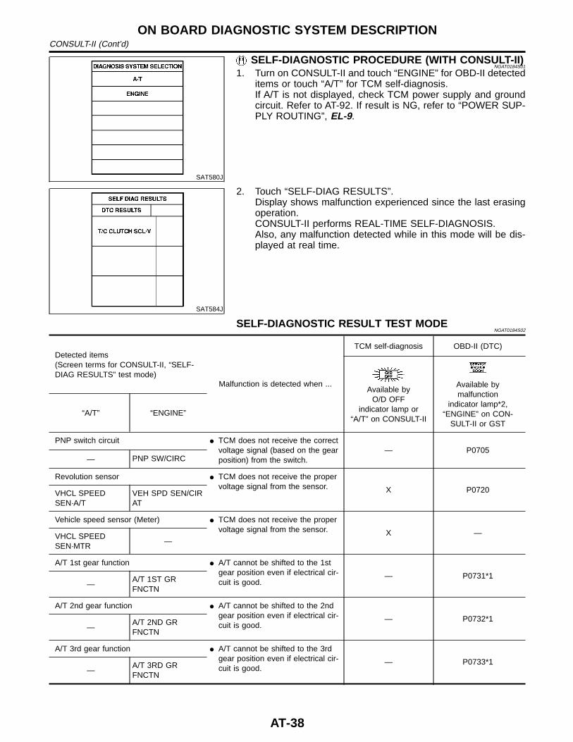
SELF-DIAGNOSTIC PROCEDURE (WITH CONSULT-II)NGAT0184S01
1. Turn on CONSULT-II and touch “ENGINE” for OBD-II detecteditems or touch “A/T” for TCM self-diagnosis.If A/T is not displayed, check TCM power supply and groundcircuit. Refer to AT-92. If result is NG, refer to “POWER SUP-PLY ROUTING”, EL-9.
SAT584J
2. Touch “SELF-DIAG RESULTS”.Display shows malfunction experienced since the last erasingoperation.CONSULT-II performs REAL-TIME SELF-DIAGNOSIS.Also, any malfunction detected while in this mode will be dis-played at real time.
SELF-DIAGNOSTIC RESULT TEST MODENGAT0184S02
Detected items(Screen terms for CONSULT-II, “SELF-DIAG RESULTS” test mode)
Malfunction is detected when ...
TCM self-diagnosis OBD-II (DTC)
Available byO/D OFF
indicator lamp or“A/T” on CONSULT-II
Available bymalfunction
indicator lamp*2,“ENGINE” on CON-
SULT-II or GST“A/T” “ENGINE”
PNP switch circuit I TCM does not receive the correctvoltage signal (based on the gearposition) from the switch.
— P0705— PNP SW/CIRC
Revolution sensor I TCM does not receive the propervoltage signal from the sensor. X P0720VHCL SPEED
SEN·A/TVEH SPD SEN/CIRAT
Vehicle speed sensor (Meter) I TCM does not receive the propervoltage signal from the sensor. X —VHCL SPEED
SEN·MTR—
A/T 1st gear function I A/T cannot be shifted to the 1stgear position even if electrical cir-cuit is good.
— P0731*1—
A/T 1ST GRFNCTN
A/T 2nd gear function I A/T cannot be shifted to the 2ndgear position even if electrical cir-cuit is good.
— P0732*1—
A/T 2ND GRFNCTN
A/T 3rd gear function I A/T cannot be shifted to the 3rdgear position even if electrical cir-cuit is good.
— P0733*1—
A/T 3RD GRFNCTN
ON BOARD DIAGNOSTIC SYSTEM DESCRIPTIONCONSULT-II (Cont’d)
AT-38
Detected items(Screen terms for CONSULT-II, “SELF-DIAG RESULTS” test mode)
Malfunction is detected when ...
TCM self-diagnosis OBD-II (DTC)
Available byO/D OFF
indicator lamp or“A/T” on CONSULT-II
Available bymalfunction
indicator lamp*2,“ENGINE” on CON-
SULT-II or GST“A/T” “ENGINE”
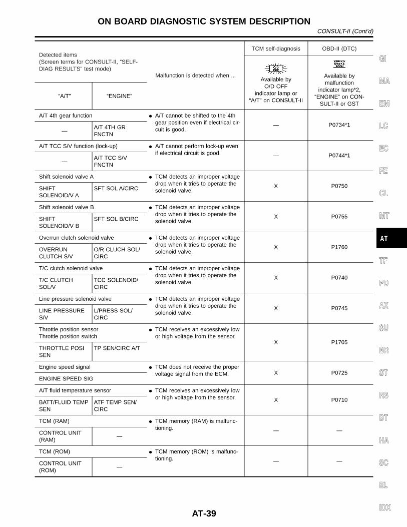
A/T 4th gear function I A/T cannot be shifted to the 4thgear position even if electrical cir-cuit is good.
— P0734*1—
A/T 4TH GRFNCTN
A/T TCC S/V function (lock-up) I A/T cannot perform lock-up evenif electrical circuit is good. — P0744*1
—A/T TCC S/VFNCTN
Shift solenoid valve A I TCM detects an improper voltagedrop when it tries to operate thesolenoid valve.
X P0750SHIFTSOLENOID/V A
SFT SOL A/CIRC
Shift solenoid valve B I TCM detects an improper voltagedrop when it tries to operate thesolenoid valve.
X P0755SHIFTSOLENOID/V B
SFT SOL B/CIRC
Overrun clutch solenoid valve I TCM detects an improper voltagedrop when it tries to operate thesolenoid valve.
X P1760OVERRUNCLUTCH S/V
O/R CLUCH SOL/CIRC
T/C clutch solenoid valve I TCM detects an improper voltagedrop when it tries to operate thesolenoid valve.
X P0740T/C CLUTCHSOL/V
TCC SOLENOID/CIRC
Line pressure solenoid valve I TCM detects an improper voltagedrop when it tries to operate thesolenoid valve.
X P0745LINE PRESSURES/V
L/PRESS SOL/CIRC
Throttle position sensorThrottle position switch
I TCM receives an excessively lowor high voltage from the sensor.
X P1705THROTTLE POSISEN
TP SEN/CIRC A/T
Engine speed signal I TCM does not receive the propervoltage signal from the ECM. X P0725
ENGINE SPEED SIG
A/T fluid temperature sensor I TCM receives an excessively lowor high voltage from the sensor. X P0710BATT/FLUID TEMP
SENATF TEMP SEN/CIRC
TCM (RAM) I TCM memory (RAM) is malfunc-tioning. — —CONTROL UNIT
(RAM)—
TCM (ROM) I TCM memory (ROM) is malfunc-tioning. — —CONTROL UNIT
(ROM)—
GI
MA
EM
LC
EC
FE
CL
MT
TF
PD
AX
SU
BR
ST
RS
BT
HA
SC
EL
IDX
ON BOARD DIAGNOSTIC SYSTEM DESCRIPTIONCONSULT-II (Cont’d)
AT-39
Detected items(Screen terms for CONSULT-II, “SELF-DIAG RESULTS” test mode)
Malfunction is detected when ...
TCM self-diagnosis OBD-II (DTC)
Available byO/D OFF
indicator lamp or“A/T” on CONSULT-II
Available bymalfunction
indicator lamp*2,“ENGINE” on CON-
SULT-II or GST“A/T” “ENGINE”
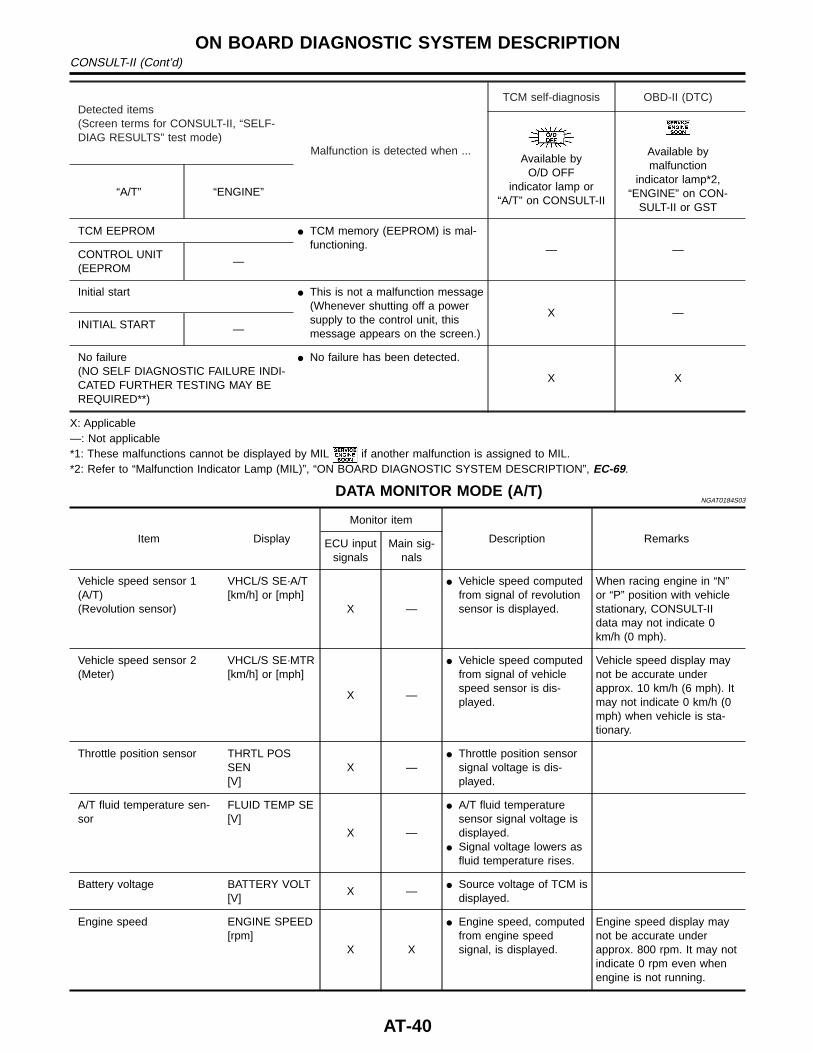
TCM EEPROM I TCM memory (EEPROM) is mal-functioning. — —CONTROL UNIT
(EEPROM—
Initial start I This is not a malfunction message(Whenever shutting off a powersupply to the control unit, thismessage appears on the screen.)
X —INITIAL START —
No failure(NO SELF DIAGNOSTIC FAILURE INDI-CATED FURTHER TESTING MAY BEREQUIRED**)
I No failure has been detected.
X X
X: Applicable—: Not applicable*1: These malfunctions cannot be displayed by MIL if another malfunction is assigned to MIL.*2: Refer to “Malfunction Indicator Lamp (MIL)”, “ON BOARD DIAGNOSTIC SYSTEM DESCRIPTION”, EC-69.
DATA MONITOR MODE (A/T)NGAT0184S03
Item Display
Monitor item
Description RemarksECU inputsignals
Main sig-nals
Vehicle speed sensor 1(A/T)(Revolution sensor)
VHCL/S SE·A/T[km/h] or [mph]
X —
I Vehicle speed computedfrom signal of revolutionsensor is displayed.
When racing engine in “N”or “P” position with vehiclestationary, CONSULT-IIdata may not indicate 0km/h (0 mph).
Vehicle speed sensor 2(Meter)
VHCL/S SE·MTR[km/h] or [mph]
X —
I Vehicle speed computedfrom signal of vehiclespeed sensor is dis-played.
Vehicle speed display maynot be accurate underapprox. 10 km/h (6 mph). Itmay not indicate 0 km/h (0mph) when vehicle is sta-tionary.
Throttle position sensor THRTL POSSEN[V]
X —I Throttle position sensor
signal voltage is dis-played.
A/T fluid temperature sen-sor
FLUID TEMP SE[V]
X —
I A/T fluid temperaturesensor signal voltage isdisplayed.
I Signal voltage lowers asfluid temperature rises.
Battery voltage BATTERY VOLT[V]
X —I Source voltage of TCM is
displayed.
Engine speed ENGINE SPEED[rpm]
X X
I Engine speed, computedfrom engine speedsignal, is displayed.
Engine speed display maynot be accurate underapprox. 800 rpm. It may notindicate 0 rpm even whenengine is not running.
ON BOARD DIAGNOSTIC SYSTEM DESCRIPTIONCONSULT-II (Cont’d)
AT-40
Item Display
Monitor item
Description RemarksECU inputsignals
Main sig-nals
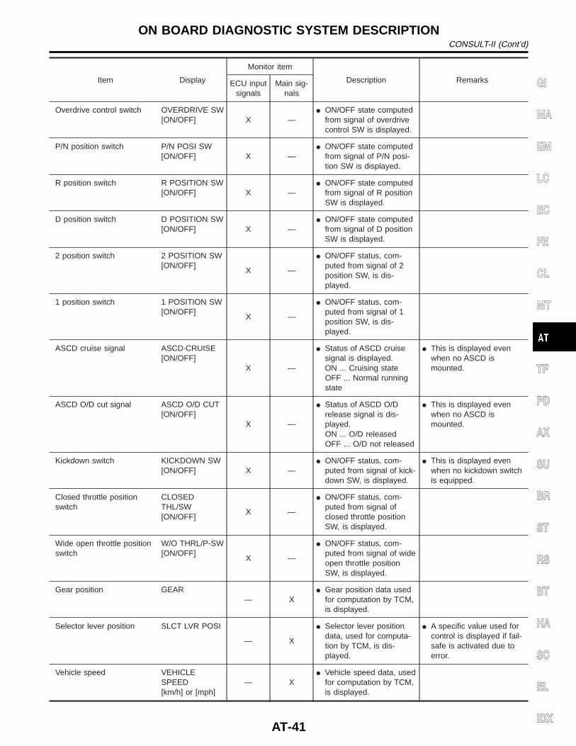
Overdrive control switch OVERDRIVE SW[ON/OFF] X —
I ON/OFF state computedfrom signal of overdrivecontrol SW is displayed.
P/N position switch P/N POSI SW[ON/OFF] X —
I ON/OFF state computedfrom signal of P/N posi-tion SW is displayed.
R position switch R POSITION SW[ON/OFF] X —
I ON/OFF state computedfrom signal of R positionSW is displayed.
D position switch D POSITION SW[ON/OFF] X —
I ON/OFF state computedfrom signal of D positionSW is displayed.
2 position switch 2 POSITION SW[ON/OFF]
X —
I ON/OFF status, com-puted from signal of 2position SW, is dis-played.
1 position switch 1 POSITION SW[ON/OFF]
X —
I ON/OFF status, com-puted from signal of 1position SW, is dis-played.
ASCD cruise signal ASCD·CRUISE[ON/OFF]
X —
I Status of ASCD cruisesignal is displayed.ON ... Cruising stateOFF ... Normal runningstate
I This is displayed evenwhen no ASCD ismounted.
ASCD O/D cut signal ASCD O/D CUT[ON/OFF]
X —
I Status of ASCD O/Drelease signal is dis-played.ON ... O/D releasedOFF ... O/D not released
I This is displayed evenwhen no ASCD ismounted.
Kickdown switch KICKDOWN SW[ON/OFF] X —
I ON/OFF status, com-puted from signal of kick-down SW, is displayed.
I This is displayed evenwhen no kickdown switchis equipped.
Closed throttle positionswitch
CLOSEDTHL/SW[ON/OFF]
X —
I ON/OFF status, com-puted from signal ofclosed throttle positionSW, is displayed.
Wide open throttle positionswitch
W/O THRL/P-SW[ON/OFF]
X —
I ON/OFF status, com-puted from signal of wideopen throttle positionSW, is displayed.
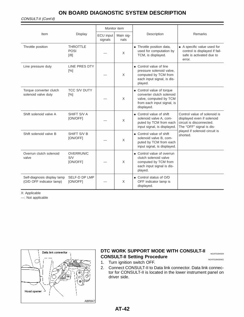
Gear position GEAR— X
I Gear position data usedfor computation by TCM,is displayed.
Selector lever position SLCT LVR POSI
— X
I Selector lever positiondata, used for computa-tion by TCM, is dis-played.
I A specific value used forcontrol is displayed if fail-safe is activated due toerror.
Vehicle speed VEHICLESPEED[km/h] or [mph]
— XI Vehicle speed data, used
for computation by TCM,is displayed.
GI
MA
EM
LC
EC
FE
CL
MT
TF
PD
AX
SU
BR
ST
RS
BT
HA
SC
EL
IDX
ON BOARD DIAGNOSTIC SYSTEM DESCRIPTIONCONSULT-II (Cont’d)
AT-41
Item Display
Monitor item
Description RemarksECU inputsignals
Main sig-nals
Throttle position THROTTLEPOSI[/8]
— X
I Throttle position data,used for computation byTCM, is displayed.
I A specific value used forcontrol is displayed if fail-safe is activated due toerror.
Line pressure duty LINE PRES DTY[%]
— X
I Control value of linepressure solenoid valve,computed by TCM fromeach input signal, is dis-played.
Torque converter clutchsolenoid valve duty
TCC S/V DUTY[%]
— X
I Control value of torqueconverter clutch solenoidvalve, computed by TCMfrom each input signal, isdisplayed.
Shift solenoid valve A SHIFT S/V A[ON/OFF]
— X
I Control value of shiftsolenoid valve A, com-puted by TCM from eachinput signal, is displayed.
Control value of solenoid isdisplayed even if solenoidcircuit is disconnected.The “OFF” signal is dis-played if solenoid circuit isshorted.Shift solenoid valve B SHIFT S/V B
[ON/OFF]— X
I Control value of shiftsolenoid valve B, com-puted by TCM from eachinput signal, is displayed.
Overrun clutch solenoidvalve
OVERRUN/CS/V[ON/OFF] — X
I Control value of overrunclutch solenoid valvecomputed by TCM fromeach input signal is dis-played.
Self-diagnosis display lamp(O/D OFF indicator lamp)
SELF-D DP LMP[ON/OFF] — X
I Control status of O/DOFF indicator lamp isdisplayed.
X: Applicable—: Not applicable
ABR847
DTC WORK SUPPORT MODE WITH CONSULT-IINGAT0184S04
CONSULT-II Setting ProcedureNGAT0184S0401
1. Turn ignition switch OFF.2. Connect CONSULT-II to Data link connector. Data link connec-
tor for CONSULT-II is located in the lower instrument panel ondriver side.
ON BOARD DIAGNOSTIC SYSTEM DESCRIPTIONCONSULT-II (Cont’d)
AT-42
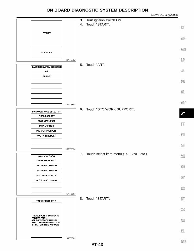
SAT586J
3. Turn ignition switch ON4. Touch “START”.
SAT580J
5. Touch “A/T”.
SAT587J
6. Touch “DTC WORK SUPPORT”.
SAT588J
7. Touch select item menu (1ST, 2ND, etc.).
SAT589J
8. Touch “START”.
GI
MA
EM
LC
EC
FE
CL
MT
TF
PD
AX
SU
BR
ST
RS
BT
HA
SC
EL
IDX
ON BOARD DIAGNOSTIC SYSTEM DESCRIPTIONCONSULT-II (Cont’d)
AT-43
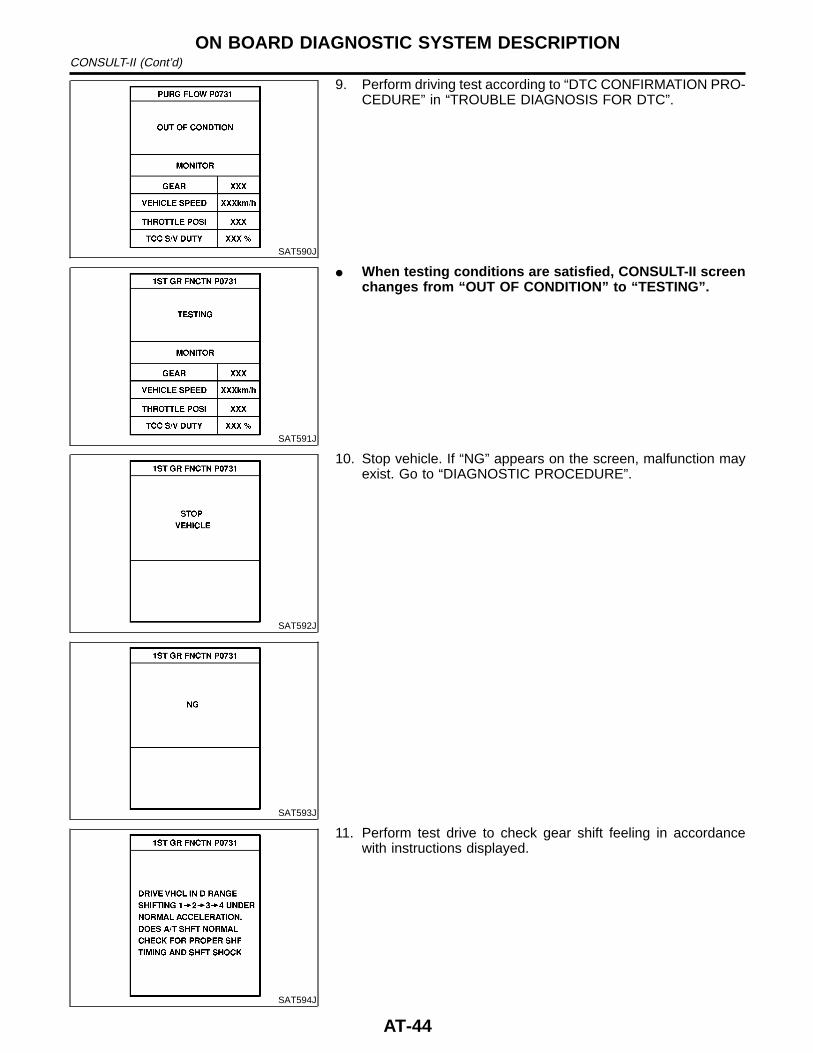
SAT590J
9. Perform driving test according to “DTC CONFIRMATION PRO-CEDURE” in “TROUBLE DIAGNOSIS FOR DTC”.
SAT591J
I When testing conditions are satisfied, CONSULT-II screenchanges from “OUT OF CONDITION” to “TESTING”.
SAT592J
SAT593J
10. Stop vehicle. If “NG” appears on the screen, malfunction mayexist. Go to “DIAGNOSTIC PROCEDURE”.
SAT594J
11. Perform test drive to check gear shift feeling in accordancewith instructions displayed.
ON BOARD DIAGNOSTIC SYSTEM DESCRIPTIONCONSULT-II (Cont’d)
AT-44
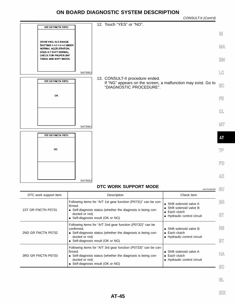
SAT595J
12. Touch “YES” or “NO”.
SAT596J
SAT593J
13. CONSULT-II procedure ended.If “NG” appears on the screen, a malfunction may exist. Go to“DIAGNOSTIC PROCEDURE”.
DTC WORK SUPPORT MODENGAT0184S05
DTC work support item Description Check item
1ST GR FNCTN P0731
Following items for “A/T 1st gear function (P0731)” can be con-firmed.I Self-diagnosis status (whether the diagnosis is being con-
ducted or not)I Self-diagnosis result (OK or NG)
I Shift solenoid valve AI Shift solenoid valve BI Each clutchI Hydraulic control circuit
2ND GR FNCTN P0732
Following items for “A/T 2nd gear function (P0732)” can beconfirmed.I Self-diagnosis status (whether the diagnosis is being con-
ducted or not)I Self-diagnosis result (OK or NG)
I Shift solenoid valve BI Each clutchI Hydraulic control circuit
3RD GR FNCTN P0733
Following items for “A/T 3rd gear function (P0733)” can be con-firmed.I Self-diagnosis status (whether the diagnosis is being con-
ducted or not)I Self-diagnosis result (OK or NG)
I Shift solenoid valve AI Each clutchI Hydraulic control circuit
GI
MA
EM
LC
EC
FE
CL
MT
TF
PD
AX
SU
BR
ST
RS
BT
HA
SC
EL
IDX
ON BOARD DIAGNOSTIC SYSTEM DESCRIPTIONCONSULT-II (Cont’d)
AT-45
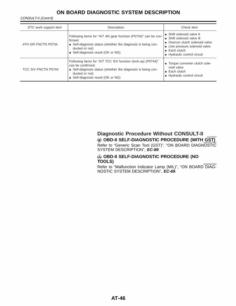
DTC work support item Description Check item
4TH GR FNCTN P0734
Following items for “A/T 4th gear function (P0734)” can be con-firmed.I Self-diagnosis status (whether the diagnosis is being con-
ducted or not)I Self-diagnosis result (OK or NG)
I Shift solenoid valve AI Shift solenoid valve BI Overrun clutch solenoid valveI Line pressure solenoid valveI Each clutchI Hydraulic control circuit
TCC S/V FNCTN P0744
Following items for “A/T TCC S/V function (lock-up) (P0744)”can be confirmed.I Self-diagnosis status (whether the diagnosis is being con-
ducted or not)I Self-diagnosis result (OK or NG)
I Torque converter clutch sole-noid valve
I Each clutchI Hydraulic control circuit
Diagnostic Procedure Without CONSULT-IINGAT0207
OBD-II SELF-DIAGNOSTIC PROCEDURE (WITH GST)NGAT0207S01
Refer to “Generic Scan Tool (GST)”, “ON BOARD DIAGNOSTICSYSTEM DESCRIPTION”, EC-89.
OBD-II SELF-DIAGNOSTIC PROCEDURE (NOTOOLS)
NGAT0207S02
Refer to “Malfunction Indicator Lamp (MIL)”, “ON BOARD DIAG-NOSTIC SYSTEM DESCRIPTION”, EC-69.
ON BOARD DIAGNOSTIC SYSTEM DESCRIPTIONCONSULT-II (Cont’d)
AT-46
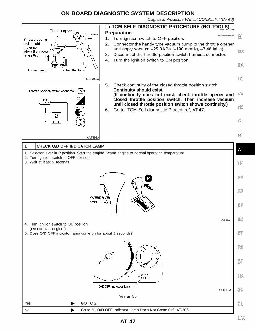
SEF793W
TCM SELF-DIAGNOSTIC PROCEDURE (NO TOOLS)NGAT0207S03
PreparationNGAT0207S0301
1. Turn ignition switch to OFF position.2. Connector the handy type vacuum pump to the throttle opener
and apply vacuum –25.3 kPa (–190 mmHg, –7.48 inHg).3. Disconnect the throttle position switch harness connector.4. Turn the ignition switch to ON position.
AAT498A
5. Check continuity of the closed throttle position switch.Continuity should exist.(If continuity does not exist, check throttle opener andclosed throttle position switch. Then increase vacuumuntil closed throttle position switch shows continuity.)
6. Go to “TCM Self-diagnostic Procedure”, AT-47.
1 CHECK O/D OFF INDICATOR LAMP
1. Selector lever in P position. Start the engine. Warm engine to normal operating temperature.2. Turn ignition switch to OFF position.3. Wait at least 5 seconds.
SAT967I
4. Turn ignition switch to ON position.(Do not start engine.)
5. Does O/D OFF indicator lamp come on for about 2 seconds?
AAT612A
Yes or No
Yes © GO TO 2.
No © Go to “1. O/D OFF Indicator Lamp Does Not Come On”, AT-206.
GI
MA
EM
LC
EC
FE
CL
MT
TF
PD
AX
SU
BR
ST
RS
BT
HA
SC
EL
IDX
ON BOARD DIAGNOSTIC SYSTEM DESCRIPTIONDiagnostic Procedure Without CONSULT-II (Cont’d)
AT-47
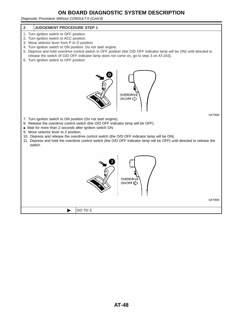
2 JUDGEMENT PROCEDURE STEP 1
1. Turn ignition switch to OFF position.2. Turn ignition switch to ACC position.3. Move selector lever from P to D position.4. Turn ignition switch to ON position. Do not start engine.5. Depress and hold overdrive control switch in OFF position (the O/D OFF indicator lamp will be ON) until directed to
release the switch (If O/D OFF indicator lamp does not come on, go to step 3 on AT-243).6. Turn ignition switch to OFF position.
SAT968I
7. Turn ignition switch to ON position (Do not start engine).8. Release the overdrive control switch (the O/D OFF indicator lamp will be OFF).I Wait for more than 2 seconds after ignition switch ON.9. Move selector lever to 2 position.10. Depress and release the overdrive control switch (the O/D OFF indicator lamp will be ON).11. Depress and hold the overdrive control switch (the O/D OFF indicator lamp will be OFF) until directed to release the
switch.
SAT969I
© GO TO 3.
ON BOARD DIAGNOSTIC SYSTEM DESCRIPTIONDiagnostic Procedure Without CONSULT-II (Cont’d)
AT-48
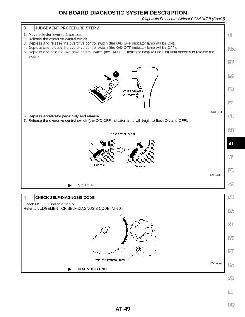
3 JUDGEMENT PROCEDURE STEP 2
1. Move selector lever to 1 position.2. Release the overdrive control switch.3. Depress and release the overdrive control switch (the O/D OFF indicator lamp will be ON).4. Depress and release the overdrive control switch (the O/D OFF indicator lamp will be OFF).5. Depress and hold the overdrive control switch (the O/D OFF indicator lamp will be ON) until directed to release the
switch.
SAT970I
6. Depress accelerator pedal fully and release.7. Release the overdrive control switch (the O/D OFF indicator lamp will begin to flash ON and OFF).
SAT981F
© GO TO 4.
4 CHECK SELF-DIAGNOSIS CODE
Check O/D OFF indicator lamp.Refer to JUDGEMENT OF SELF-DIAGNOSIS CODE, AT-50.
AAT612A
© DIAGNOSIS END
GI
MA
EM
LC
EC
FE
CL
MT
TF
PD
AX
SU
BR
ST
RS
BT
HA
SC
EL
IDX
ON BOARD DIAGNOSTIC SYSTEM DESCRIPTIONDiagnostic Procedure Without CONSULT-II (Cont’d)
AT-49
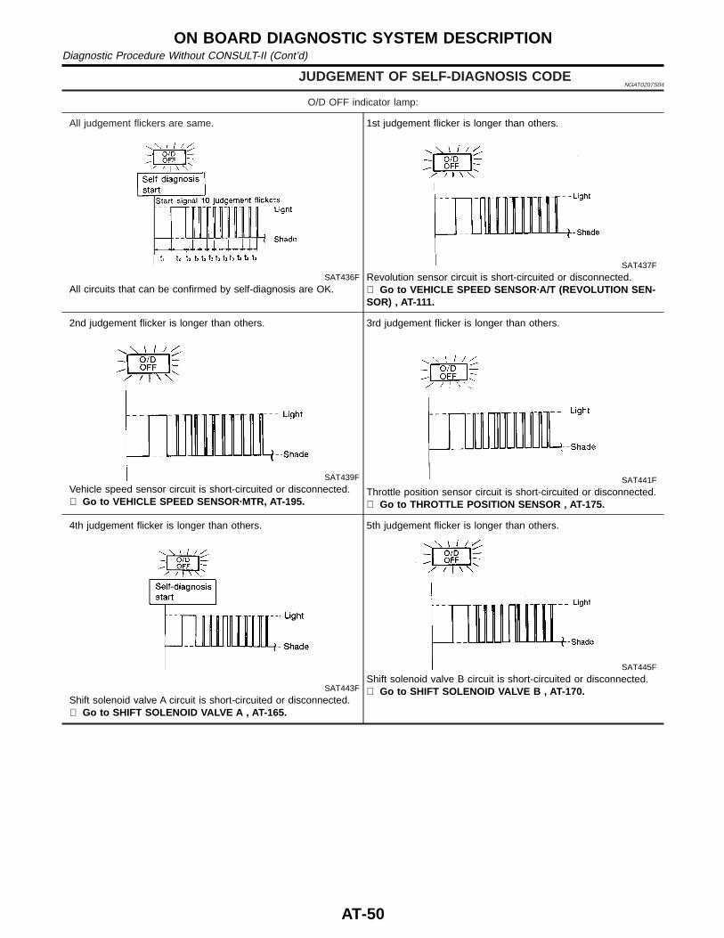
JUDGEMENT OF SELF-DIAGNOSIS CODENGAT0207S04
O/D OFF indicator lamp:
All judgement flickers are same.
SAT436F
All circuits that can be confirmed by self-diagnosis are OK.
1st judgement flicker is longer than others.
SAT437F
Revolution sensor circuit is short-circuited or disconnected.⇒ Go to VEHICLE SPEED SENSOR·A/T (REVOLUTION SEN-SOR) , AT-111.
2nd judgement flicker is longer than others.
SAT439F
Vehicle speed sensor circuit is short-circuited or disconnected.⇒ Go to VEHICLE SPEED SENSOR·MTR, AT-195.
3rd judgement flicker is longer than others.
SAT441F
Throttle position sensor circuit is short-circuited or disconnected.⇒ Go to THROTTLE POSITION SENSOR , AT-175.
4th judgement flicker is longer than others.
SAT443F
Shift solenoid valve A circuit is short-circuited or disconnected.⇒ Go to SHIFT SOLENOID VALV E A , AT-165.
5th judgement flicker is longer than others.
SAT445F
Shift solenoid valve B circuit is short-circuited or disconnected.⇒ Go to SHIFT SOLENOID VALVE B , AT-170.
ON BOARD DIAGNOSTIC SYSTEM DESCRIPTIONDiagnostic Procedure Without CONSULT-II (Cont’d)
AT-50
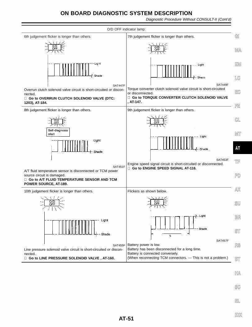
O/D OFF indicator lamp:
6th judgement flicker is longer than others.
SAT447F
Overrun clutch solenoid valve circuit is short-circuited or discon-nected.⇒ Go to OVERRUN CLUTCH SOLENOID VALVE (DTC:1203), AT-184.
7th judgement flicker is longer than others.
SAT449F
Torque converter clutch solenoid valve circuit is short-circuitedor disconnected.⇒ Go to TORQUE CONVERTER CLUTCH SOLENOID VALVE, AT-147.
8th judgement flicker is longer than others.
SAT451F
A/T fluid temperature sensor is disconnected or TCM powersource circuit is damaged.⇒ Go to A/T FLUID TEMPERATURE SENSOR AND TCMPOWER SOURCE, AT-189.
9th judgement flicker is longer than others.
SAT453F
Engine speed signal circuit is short-circuited or disconnected.⇒ Go to ENGINE SPEED SIGNAL AT-116.
10th judgement flicker is longer than others.
SAT455F
Line pressure solenoid valve circuit is short-circuited or discon-nected.⇒ Go to LINE PRESSURE SOLENOID VALVE , AT-160.
Flickers as shown below.
SAT457F
Battery power is low.Battery has been disconnected for a long time.Battery is connected conversely.(When reconnecting TCM connectors. — This is not a problem.)
GI
MA
EM
LC
EC
FE
CL
MT
TF
PD
AX
SU
BR
ST
RS
BT
HA
SC
EL
IDX
ON BOARD DIAGNOSTIC SYSTEM DESCRIPTIONDiagnostic Procedure Without CONSULT-II (Cont’d)
AT-51
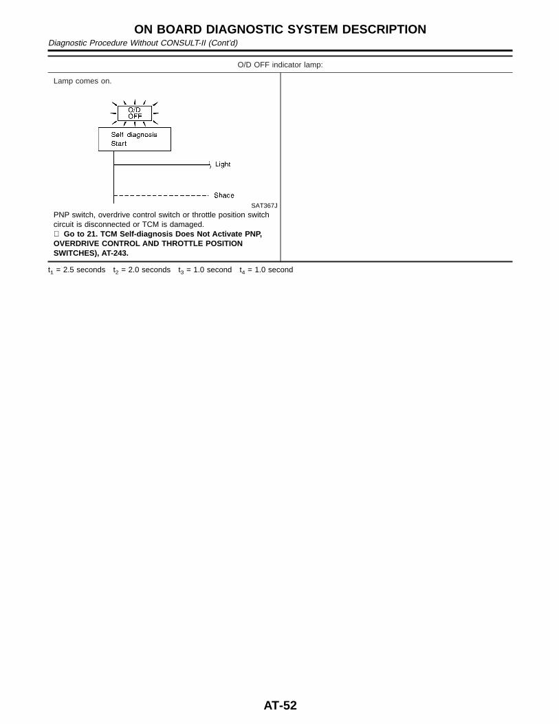
O/D OFF indicator lamp:
Lamp comes on.
SAT367J
PNP switch, overdrive control switch or throttle position switchcircuit is disconnected or TCM is damaged.⇒ Go to 21. TCM Self-diagnosis Does Not Activate PNP,OVERDRIVE CONTROL AND THROTTLE POSITIONSWITCHES), AT-243.
t1 = 2.5 seconds t2 = 2.0 seconds t3 = 1.0 second t4 = 1.0 second
ON BOARD DIAGNOSTIC SYSTEM DESCRIPTIONDiagnostic Procedure Without CONSULT-II (Cont’d)
AT-52
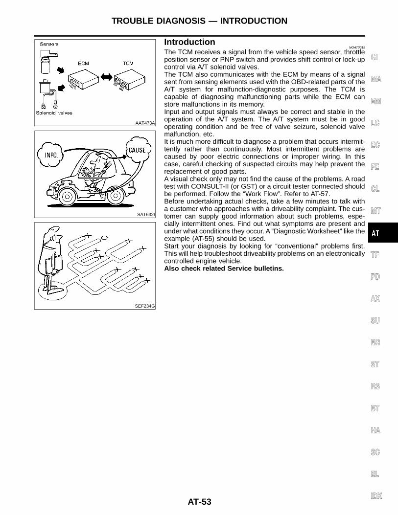
AAT473A
SAT632I
SEF234G
IntroductionNGAT0019
The TCM receives a signal from the vehicle speed sensor, throttleposition sensor or PNP switch and provides shift control or lock-upcontrol via A/T solenoid valves.The TCM also communicates with the ECM by means of a signalsent from sensing elements used with the OBD-related parts of theA/T system for malfunction-diagnostic purposes. The TCM iscapable of diagnosing malfunctioning parts while the ECM canstore malfunctions in its memory.Input and output signals must always be correct and stable in theoperation of the A/T system. The A/T system must be in goodoperating condition and be free of valve seizure, solenoid valvemalfunction, etc.It is much more difficult to diagnose a problem that occurs intermit-tently rather than continuously. Most intermittent problems arecaused by poor electric connections or improper wiring. In thiscase, careful checking of suspected circuits may help prevent thereplacement of good parts.A visual check only may not find the cause of the problems. A roadtest with CONSULT-II (or GST) or a circuit tester connected shouldbe performed. Follow the “Work Flow”. Refer to AT-57.Before undertaking actual checks, take a few minutes to talk witha customer who approaches with a driveability complaint. The cus-tomer can supply good information about such problems, espe-cially intermittent ones. Find out what symptoms are present andunder what conditions they occur. A “Diagnostic Worksheet” like theexample (AT-55) should be used.Start your diagnosis by looking for “conventional” problems first.This will help troubleshoot driveability problems on an electronicallycontrolled engine vehicle.Also check related Service bulletins.
GI
MA
EM
LC
EC
FE
CL
MT
TF
PD
AX
SU
BR
ST
RS
BT
HA
SC
EL
IDX
TROUBLE DIAGNOSIS — INTRODUCTION
AT-53
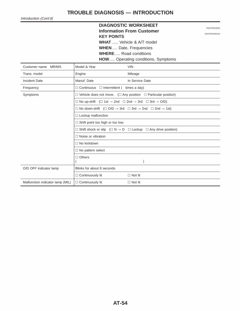
DIAGNOSTIC WORKSHEET=NGAT0019S01
Information From CustomerNGAT0019S0101
KEY POINTSWHAT ..... Vehicle & A/T modelWHEN..... Date, FrequenciesWHERE..... Road conditionsHOW..... Operating conditions, Symptoms
Customer name MR/MS Model & Year VIN
Trans. model Engine Mileage
Incident Date Manuf. Date In Service Date
Frequency l Continuous l Intermittent ( times a day)
Symptoms l Vehicle does not move. (l Any position l Particular position)
l No up-shift (l 1st , 2nd l 2nd , 3rd l 3rd , O/D)
l No down-shift (l O/D , 3rd l 3rd , 2nd l 2nd , 1st)
l Lockup malfunction
l Shift point too high or too low.
l Shift shock or slip (l N , D l Lockup l Any drive position)
l Noise or vibration
l No kickdown
l No pattern select
l Others( )
O/D OFF indicator lamp Blinks for about 8 seconds.
l Continuously lit l Not lit
Malfunction indicator lamp (MIL) l Continuously lit l Not lit
TROUBLE DIAGNOSIS — INTRODUCTIONIntroduction (Cont’d)
AT-54
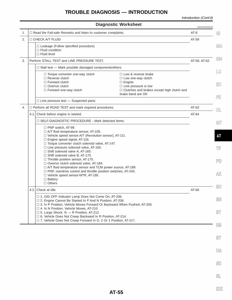
Diagnostic Worksheet=NGAT0019S0102
1. l Read the Fail-safe Remarks and listen to customer complaints. AT-8
2. l CHECK A/T FLUID AT-59
l Leakage (Follow specified procedure)l Fluid conditionl Fluid level
3. Perform STALL TEST and LINE PRESSURE TEST. AT-59, AT-62
l Stall test — Mark possible damaged components/others.
l Torque converter one-way clutchl Reverse clutchl Forward clutchl Overrun clutchl Forward one-way clutch
l Low & reverse brakel Low one-way clutchl Enginel Line pressure is lowl Clutches and brakes except high clutch andbrake band are OK
l Line pressure test — Suspected parts:
4. l Perform all ROAD TEST and mark required procedures. AT-63
4-1. Check before engine is started. AT-64
l SELF-DIAGNOSTIC PROCEDURE - Mark detected items.
l PNP switch, AT-99.l A/T fluid temperature sensor, AT-105.l Vehicle speed sensor·A/T (Revolution sensor), AT-111.l Engine speed signal, AT-116.l Torque converter clutch solenoid valve, AT-147.l Line pressure solenoid valve, AT-160.l Shift solenoid valve A, AT-165.l Shift solenoid valve B, AT-170.l Throttle position sensor, AT-175.l Overrun clutch solenoid valve, AT-184.l A/T fluid temperature sensor and TCM power source, AT-189.l PNP, overdrive control and throttle position switches, AT-243.l Vehicle speed sensor·MTR, AT-195.l Batteryl Others
4-2. Check at idle AT-66
l 1. O/D OFF Indicator Lamp Does Not Come On, AT-206.l 2. Engine Cannot Be Started In P And N Position, AT-208.l 3. In P Position, Vehicle Moves Forward Or Backward When Pushed, AT-209.l 4. In N Position, Vehicle Moves, AT-210.l 5. Large Shock. N , R Position, AT-212.l 6. Vehicle Does Not Creep Backward In R Position, AT-214.l 7. Vehicle Does Not Creep Forward In D, 2 Or 1 Position, AT-217.
GI
MA
EM
LC
EC
FE
CL
MT
TF
PD
AX
SU
BR
ST
RS
BT
HA
SC
EL
IDX
TROUBLE DIAGNOSIS — INTRODUCTIONIntroduction (Cont’d)
AT-55
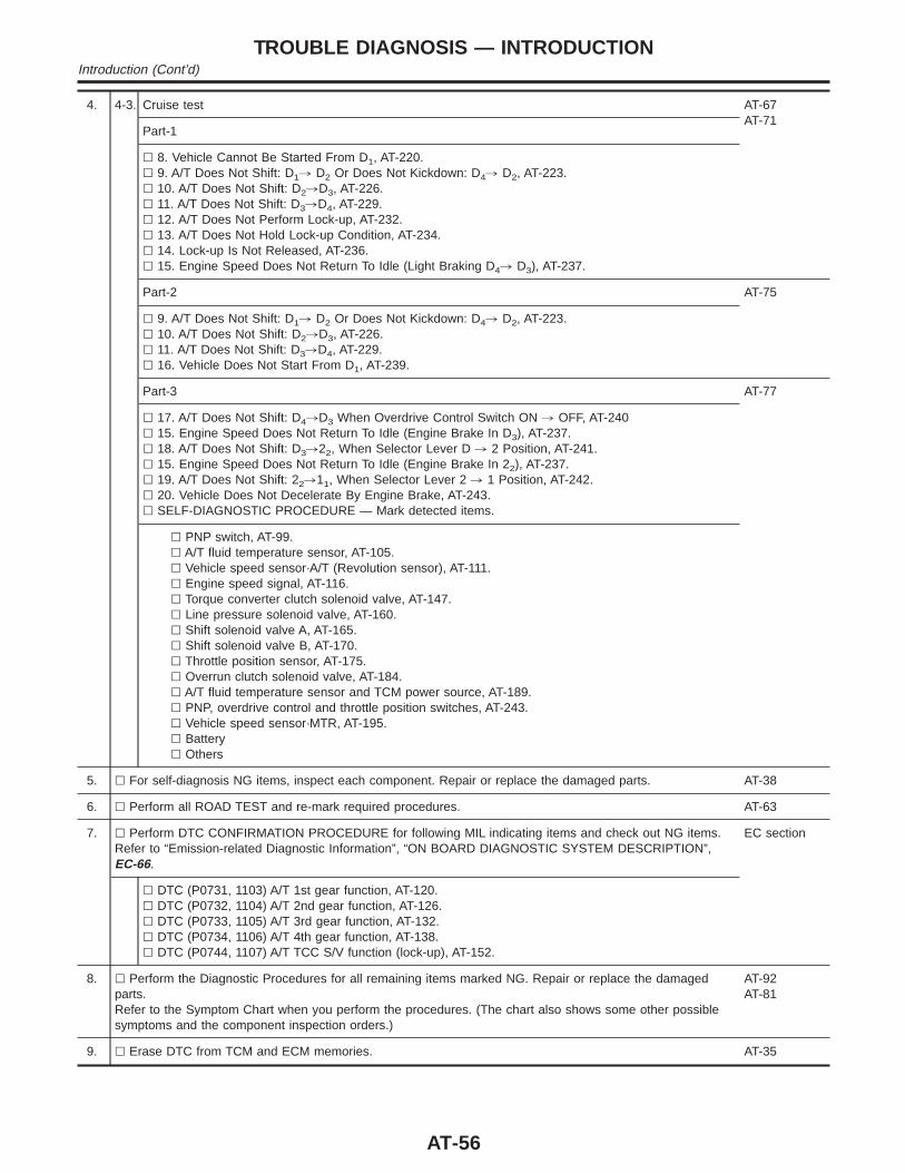
4. 4-3. Cruise test AT-67AT-71
Part-1
l 8. Vehicle Cannot Be Started From D1, AT-220.l 9. A/T Does Not Shift: D1, D2 Or Does Not Kickdown: D4, D2, AT-223.l 10. A/T Does Not Shift: D2,D3, AT-226.l 11. A/T Does Not Shift: D3,D4, AT-229.l 12. A/T Does Not Perform Lock-up, AT-232.l 13. A/T Does Not Hold Lock-up Condition, AT-234.l 14. Lock-up Is Not Released, AT-236.l 15. Engine Speed Does Not Return To Idle (Light Braking D4, D3), AT-237.
Part-2 AT-75
l 9. A/T Does Not Shift: D1, D2 Or Does Not Kickdown: D4, D2, AT-223.l 10. A/T Does Not Shift: D2,D3, AT-226.l 11. A/T Does Not Shift: D3,D4, AT-229.l 16. Vehicle Does Not Start From D1, AT-239.
Part-3 AT-77
l 17. A/T Does Not Shift: D4,D3 When Overdrive Control Switch ON , OFF, AT-240l 15. Engine Speed Does Not Return To Idle (Engine Brake In D3), AT-237.l 18. A/T Does Not Shift: D3,22, When Selector Lever D , 2 Position, AT-241.l 15. Engine Speed Does Not Return To Idle (Engine Brake In 22), AT-237.l 19. A/T Does Not Shift: 22,11, When Selector Lever 2 , 1 Position, AT-242.l 20. Vehicle Does Not Decelerate By Engine Brake, AT-243.l SELF-DIAGNOSTIC PROCEDURE — Mark detected items.
l PNP switch, AT-99.l A/T fluid temperature sensor, AT-105.l Vehicle speed sensor·A/T (Revolution sensor), AT-111.l Engine speed signal, AT-116.l Torque converter clutch solenoid valve, AT-147.l Line pressure solenoid valve, AT-160.l Shift solenoid valve A, AT-165.l Shift solenoid valve B, AT-170.l Throttle position sensor, AT-175.l Overrun clutch solenoid valve, AT-184.l A/T fluid temperature sensor and TCM power source, AT-189.l PNP, overdrive control and throttle position switches, AT-243.l Vehicle speed sensor·MTR, AT-195.l Batteryl Others
5. l For self-diagnosis NG items, inspect each component. Repair or replace the damaged parts. AT-38
6. l Perform all ROAD TEST and re-mark required procedures. AT-63
7. l Perform DTC CONFIRMATION PROCEDURE for following MIL indicating items and check out NG items.Refer to “Emission-related Diagnostic Information”, “ON BOARD DIAGNOSTIC SYSTEM DESCRIPTION”,EC-66.
EC section
l DTC (P0731, 1103) A/T 1st gear function, AT-120.l DTC (P0732, 1104) A/T 2nd gear function, AT-126.l DTC (P0733, 1105) A/T 3rd gear function, AT-132.l DTC (P0734, 1106) A/T 4th gear function, AT-138.l DTC (P0744, 1107) A/T TCC S/V function (lock-up), AT-152.
8. l Perform the Diagnostic Procedures for all remaining items marked NG. Repair or replace the damagedparts.Refer to the Symptom Chart when you perform the procedures. (The chart also shows some other possiblesymptoms and the component inspection orders.)
AT-92AT-81
9. l Erase DTC from TCM and ECM memories. AT-35
TROUBLE DIAGNOSIS — INTRODUCTIONIntroduction (Cont’d)
AT-56
Work FlowNGAT0020
HOW TO PERFORM TROUBLE DIAGNOSES FOR QUICK AND ACCURATE REPAIRNGAT0020S01
A good understanding of the malfunction conditions can make troubleshooting faster and more accurate.In general, each customer feels differently about a problem. It is important to fully understand the symptomsor conditions for a customer complaint.Make good use of the two sheets provided, “INFORMATION FROM CUSTOMER” (AT-54) and “DIAGNOS-TIC WORKSHEET” (AT-55), to perform the best troubleshooting possible.
GI
MA
EM
LC
EC
FE
CL
MT
TF
PD
AX
SU
BR
ST
RS
BT
HA
SC
EL
IDX
TROUBLE DIAGNOSIS — INTRODUCTIONWork Flow
AT-57
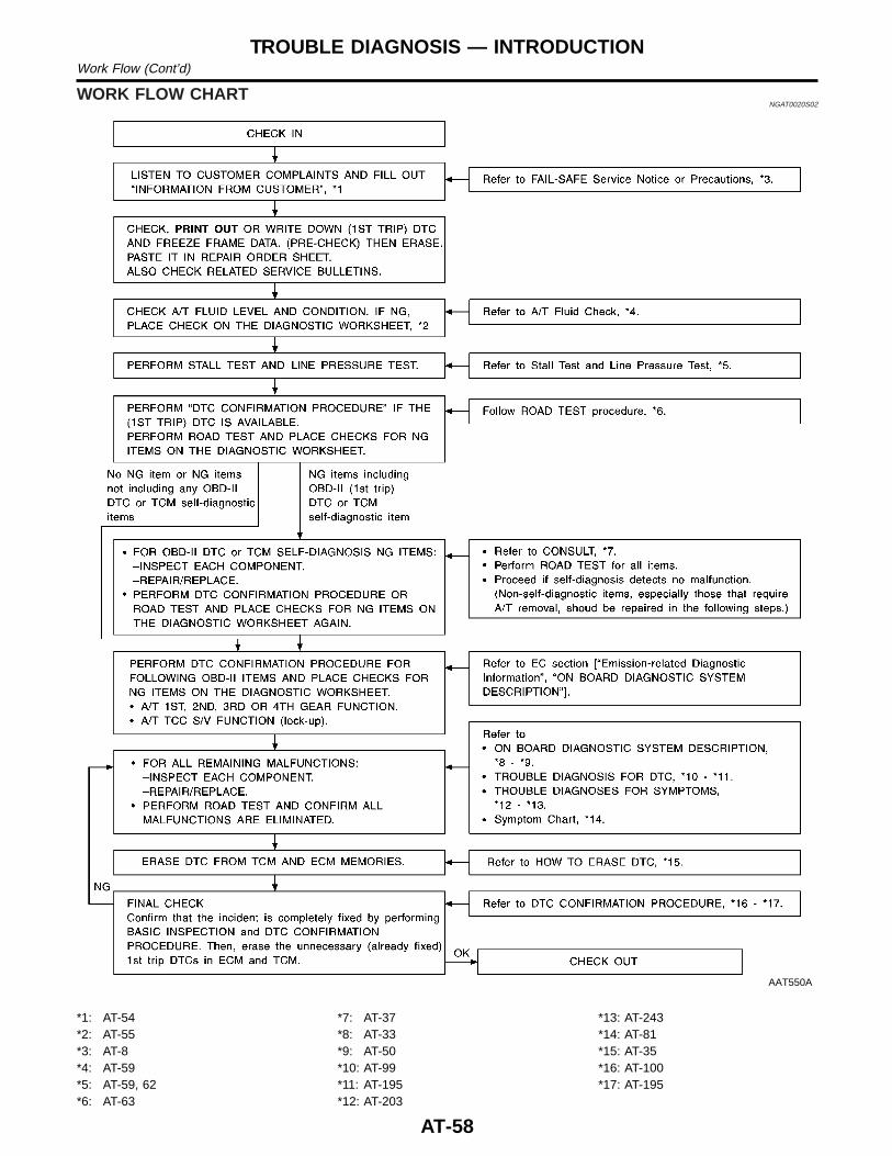
WORK FLOW CHARTNGAT0020S02
AAT550A
*1: AT-54*2: AT-55*3: AT-8*4: AT-59*5: AT-59, 62*6: AT-63
*7: AT-37*8: AT-33*9: AT-50*10: AT-99*11: AT-195*12: AT-203
*13: AT-243*14: AT-81*15: AT-35*16: AT-100*17: AT-195
TROUBLE DIAGNOSIS — INTRODUCTIONWork Flow (Cont’d)
AT-58
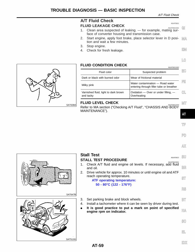
A/T Fluid CheckNGAT0021
FLUID LEAKAGE CHECKNGAT0021S01
1. Clean area suspected of leaking. — for example, mating sur-face of converter housing and transmission case.
2. Start engine, apply foot brake, place selector lever in D posi-tion and wait a few minutes.
3. Stop engine.4. Check for fresh leakage.
SAT638A
FLUID CONDITION CHECKNGAT0021S02
Fluid color Suspected problem
Dark or black with burned odor Wear of frictional material
Milky pinkWater contamination — Road waterentering through filler tube or breather
Varnished fluid, light to dark brownand tacky
Oxidation — Over or under filling, —Overheating
FLUID LEVEL CHECKNGAT0021S03
Refer to MA section (“Checking A/T Fluid”, “CHASSIS AND BODYMAINTENANCE”).
SAT647B
Stall TestNGAT0022
STALL TEST PROCEDURENGAT0022S01
1. Check A/T fluid and engine oil levels. If necessary, add fluidand oil.
2. Drive vehicle for approx. 10 minutes or until engine oil and ATFreach operating temperature.
ATF operating temperature:50 - 80°C (122 - 176°F)
SAT513G
3. Set parking brake and block wheels.4. Install a tachometer where it can be seen by driver during test.I It is good practice to put a mark on point of specified
engine rpm on indicator.
GI
MA
EM
LC
EC
FE
CL
MT
TF
PD
AX
SU
BR
ST
RS
BT
HA
SC
EL
IDX
TROUBLE DIAGNOSIS — BASIC INSPECTIONA/T Fluid Check
AT-59
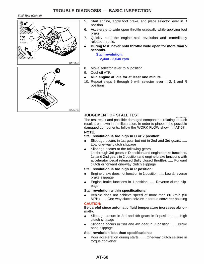
SAT514G
5. Start engine, apply foot brake, and place selector lever in Dposition.
6. Accelerate to wide open throttle gradually while applying footbrake.
7. Quickly note the engine stall revolution and immediatelyrelease throttle.
I During test, never hold throttle wide open for more than 5seconds.
Stall revolution:2,440 - 2,640 rpm
SAT771B
8. Move selector lever to N position.9. Cool off ATF.I Run engine at idle for at least one minute.10. Repeat steps 5 through 9 with selector lever in 2, 1 and R
positions.
JUDGEMENT OF STALL TESTNGAT0022S02
The test result and possible damaged components relating to eachresult are shown in the illustration. In order to pinpoint the possibledamaged components, follow the WORK FLOW shown in AT-57.NOTE:Stall revolution is too high in D or 2 position:I Slippage occurs in 1st gear but not in 2nd and 3rd gears. .....
Low one-way clutch slippageI Slippage occurs at the following gears:
1st through 3rd gears in D position and engine brake functions.1st and 2nd gears in 2 position and engine brake functions withaccelerator pedal released (fully closed throttle). ..... Forwardclutch or forward one-way clutch slippage
Stall revolution is too high in R position:I Engine brake does not function in 1 position. ..... Low & reverse
brake slippageI Engine brake functions in 1 position. ..... Reverse clutch slip-
pageStall revolution within specifications:I Vehicle does not achieve speed of more than 80 km/h (50
MPH). ..... One-way clutch seizure in torque converter housingCAUTION:Be careful since automatic fluid temperature increases abnor-mally.I Slippage occurs in 3rd and 4th gears in D position. ..... High
clutch slippageI Slippage occurs in 2nd and 4th gear in D position. ..... Brake
band slippageStall revolution less than specifications:I Poor acceleration during starts. ..... One-way clutch seizure in
torque converter
TROUBLE DIAGNOSIS — BASIC INSPECTIONStall Test (Cont’d)
AT-60
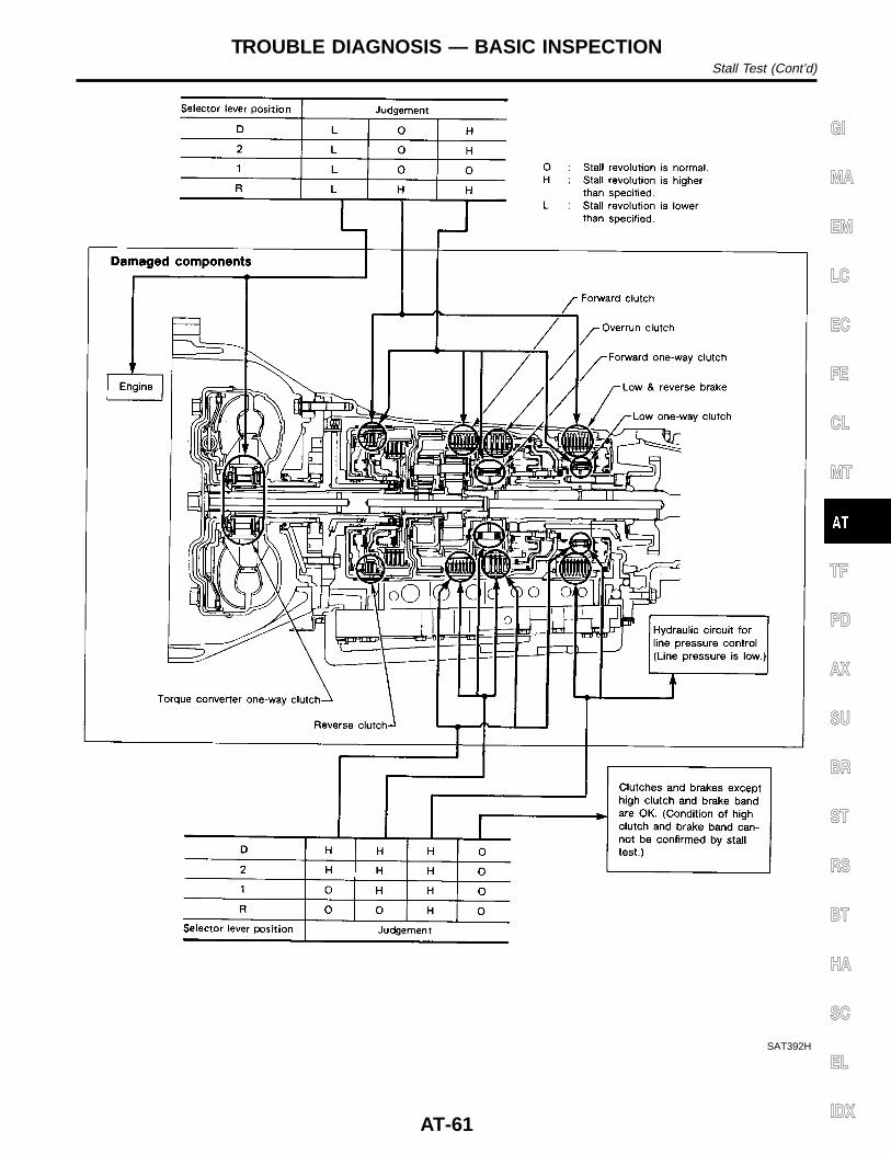
SAT392H
GI
MA
EM
LC
EC
FE
CL
MT
TF
PD
AX
SU
BR
ST
RS
BT
HA
SC
EL
IDX
TROUBLE DIAGNOSIS — BASIC INSPECTIONStall Test (Cont’d)
AT-61
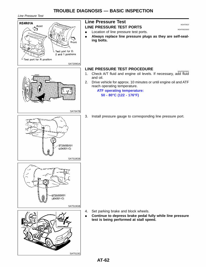
SAT209GA
Line Pressure TestNGAT0023
LINE PRESSURE TEST PORTSNGAT0023S03
I Location of line pressure test ports.I Always replace line pressure plugs as they are self-seal-
ing bolts.
SAT647B
LINE PRESSURE TEST PROCEDURENGAT0023S01
1. Check A/T fluid and engine oil levels. If necessary, add fluidand oil.
2. Drive vehicle for approx. 10 minutes or until engine oil and ATFreach operating temperature.
ATF operating temperature:50 - 80°C (122 - 176°F)
SAT518GB
SAT519GB
3. Install pressure gauge to corresponding line pressure port.
SAT513G
4. Set parking brake and block wheels.I Continue to depress brake pedal fully while line pressure
test is being performed at stall speed.
TROUBLE DIAGNOSIS — BASIC INSPECTIONLine Pressure Test
AT-62
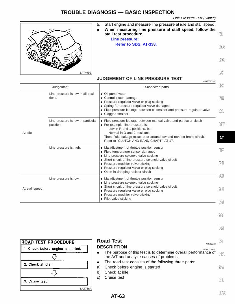
SAT493G
5. Start engine and measure line pressure at idle and stall speed.I When measuring line pressure at stall speed, follow the
stall test procedure.Line pressure:
Refer to SDS, AT-338.
JUDGEMENT OF LINE PRESSURE TESTNGAT0023S02
Judgement Suspected parts
At idle
Line pressure is low in all posi-tions.
I Oil pump wearI Control piston damageI Pressure regulator valve or plug stickingI Spring for pressure regulator valve damagedI Fluid pressure leakage between oil strainer and pressure regulator valveI Clogged strainer
Line pressure is low in particularposition.
I Fluid pressure leakage between manual valve and particular clutchI For example, line pressure is:
— Low in R and 1 positions, but— Normal in D and 2 positions.Then, fluid leakage exists at or around low and reverse brake circuit.Refer to “CLUTCH AND BAND CHART”, AT-17.
Line pressure is high. I Maladjustment of throttle position sensorI Fluid temperature sensor damagedI Line pressure solenoid valve stickingI Short circuit of line pressure solenoid valve circuitI Pressure modifier valve stickingI Pressure regulator valve or plug stickingI Open in dropping resistor circuit
At stall speed
Line pressure is low. I Maladjustment of throttle position sensorI Line pressure solenoid valve stickingI Short circuit of line pressure solenoid valve circuitI Pressure regulator valve or plug stickingI Pressure modifier valve stickingI Pilot valve sticking
SAT786A
Road TestNGAT0024
DESCRIPTIONNGAT0024S01
I The purpose of this test is to determine overall performance ofthe A/T and analyze causes of problems.
I The road test consists of the following three parts:a) Check before engine is startedb) Check at idlec) Cruise test
GI
MA
EM
LC
EC
FE
CL
MT
TF
PD
AX
SU
BR
ST
RS
BT
HA
SC
EL
IDX
TROUBLE DIAGNOSIS — BASIC INSPECTIONLine Pressure Test (Cont’d)
AT-63
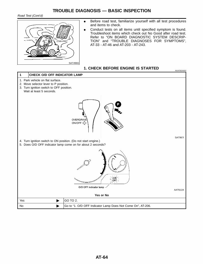
SAT496G
I Before road test, familiarize yourself with all test proceduresand items to check.
I Conduct tests on all items until specified symptom is found.Troubleshoot items which check out No Good after road test.Refer to “ON BOARD DIAGNOSTIC SYSTEM DESCRIP-TION” and “TROUBLE DIAGNOSES FOR SYMPTOMS”,AT-33 - AT-46 and AT-203 - AT-243.
1. CHECK BEFORE ENGINE IS STARTEDNGAT0024S02
1 CHECK O/D OFF INDICATOR LAMP
1. Park vehicle on flat surface.2. Move selector lever to P position.3. Turn ignition switch to OFF position.
Wait at least 5 seconds.
SAT967I
4. Turn ignition switch to ON position. (Do not start engine.)5. Does O/D OFF indicator lamp come on for about 2 seconds?
AAT612A
Yes or No
Yes © GO TO 2.
No © Go to “1. O/D OFF Indicator Lamp Does Not Come On”, AT-206.
TROUBLE DIAGNOSIS — BASIC INSPECTIONRoad Test (Cont’d)
AT-64
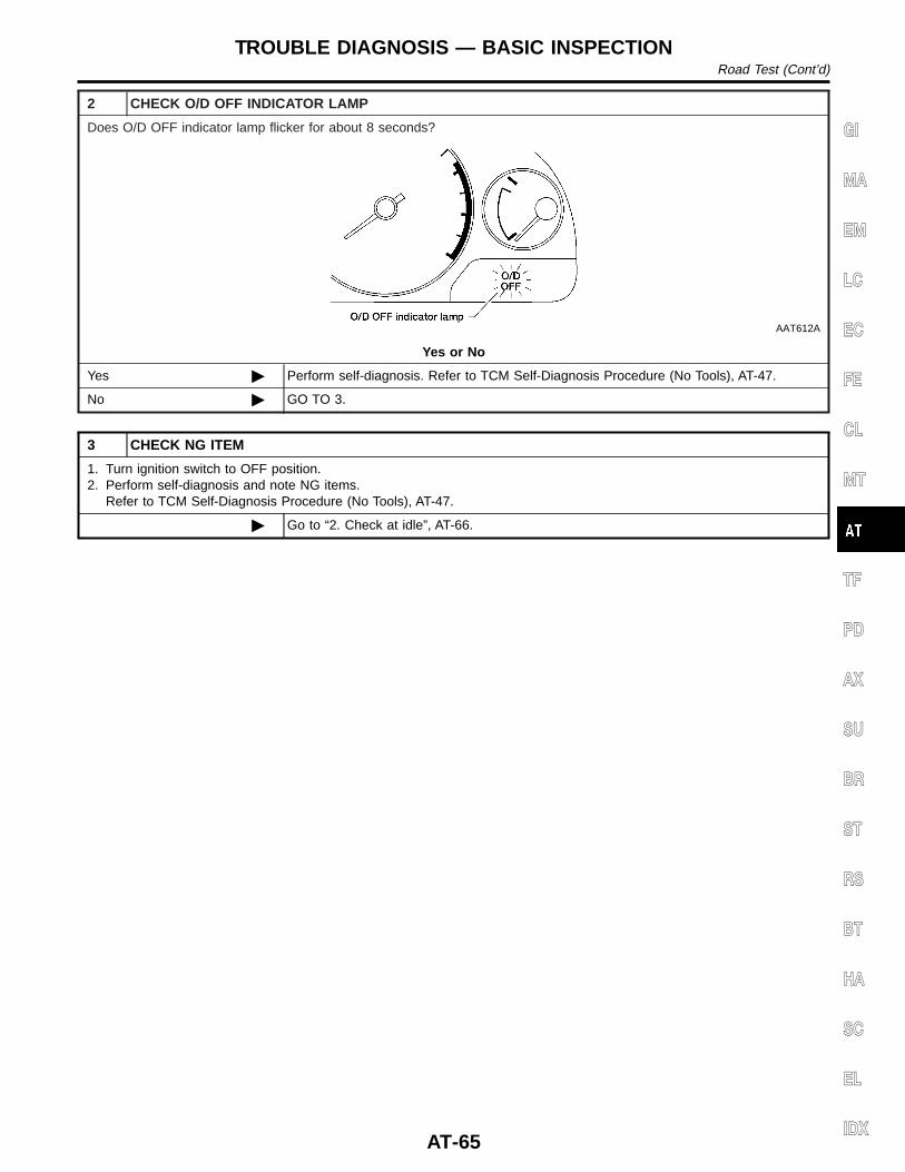
2 CHECK O/D OFF INDICATOR LAMP
Does O/D OFF indicator lamp flicker for about 8 seconds?
AAT612A
Yes or No
Yes © Perform self-diagnosis. Refer to TCM Self-Diagnosis Procedure (No Tools), AT-47.
No © GO TO 3.
3 CHECK NG ITEM
1. Turn ignition switch to OFF position.2. Perform self-diagnosis and note NG items.
Refer to TCM Self-Diagnosis Procedure (No Tools), AT-47.
© Go to “2. Check at idle”, AT-66.
GI
MA
EM
LC
EC
FE
CL
MT
TF
PD
AX
SU
BR
ST
RS
BT
HA
SC
EL
IDX
TROUBLE DIAGNOSIS — BASIC INSPECTIONRoad Test (Cont’d)
AT-65
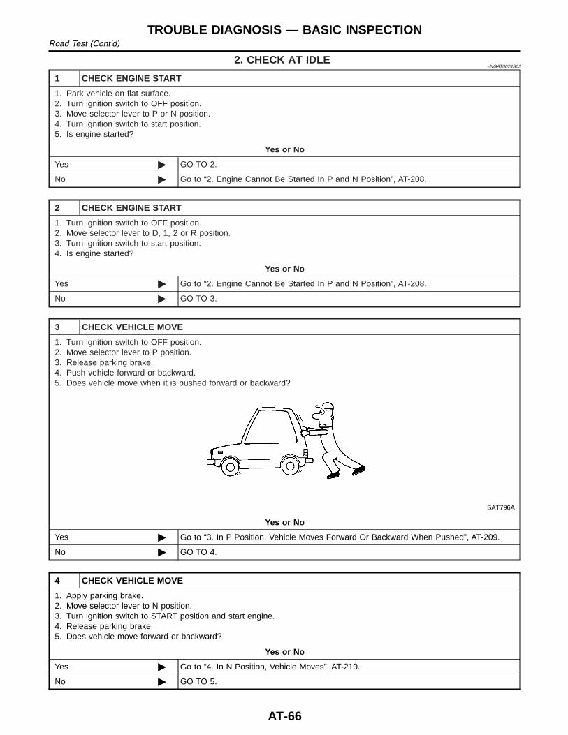
2. CHECK AT IDLE=NGAT0024S03
1 CHECK ENGINE START
1. Park vehicle on flat surface.2. Turn ignition switch to OFF position.3. Move selector lever to P or N position.4. Turn ignition switch to start position.5. Is engine started?
Yes or No
Yes © GO TO 2.
No © Go to “2. Engine Cannot Be Started In P and N Position”, AT-208.
2 CHECK ENGINE START
1. Turn ignition switch to OFF position.2. Move selector lever to D, 1, 2 or R position.3. Turn ignition switch to start position.4. Is engine started?
Yes or No
Yes © Go to “2. Engine Cannot Be Started In P and N Position”, AT-208.
No © GO TO 3.
3 CHECK VEHICLE MOVE
1. Turn ignition switch to OFF position.2. Move selector lever to P position.3. Release parking brake.4. Push vehicle forward or backward.5. Does vehicle move when it is pushed forward or backward?
SAT796A
Yes or No
Yes © Go to “3. In P Position, Vehicle Moves Forward Or Backward When Pushed”, AT-209.
No © GO TO 4.
4 CHECK VEHICLE MOVE
1. Apply parking brake.2. Move selector lever to N position.3. Turn ignition switch to START position and start engine.4. Release parking brake.5. Does vehicle move forward or backward?
Yes or No
Yes © Go to “4. In N Position, Vehicle Moves”, AT-210.
No © GO TO 5.
TROUBLE DIAGNOSIS — BASIC INSPECTIONRoad Test (Cont’d)
AT-66
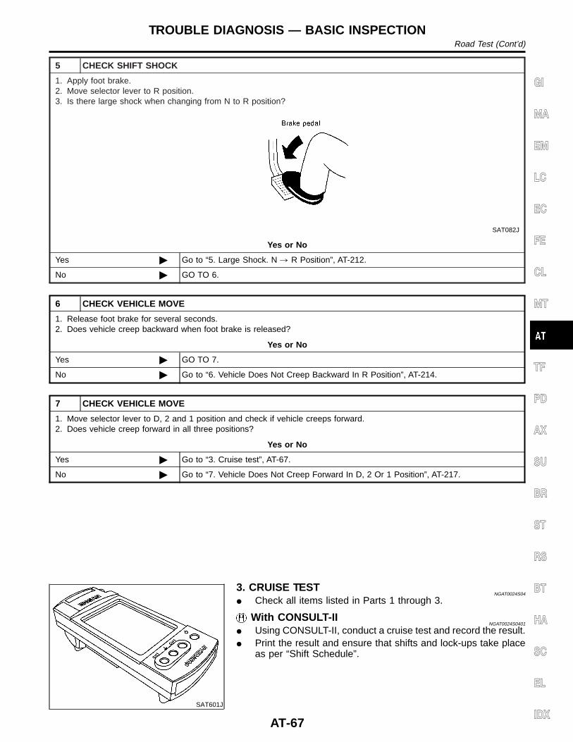
5 CHECK SHIFT SHOCK
1. Apply foot brake.2. Move selector lever to R position.3. Is there large shock when changing from N to R position?
SAT082J
Yes or No
Yes © Go to “5. Large Shock. N , R Position”, AT-212.
No © GO TO 6.
6 CHECK VEHICLE MOVE
1. Release foot brake for several seconds.2. Does vehicle creep backward when foot brake is released?
Yes or No
Yes © GO TO 7.
No © Go to “6. Vehicle Does Not Creep Backward In R Position”, AT-214.
7 CHECK VEHICLE MOVE
1. Move selector lever to D, 2 and 1 position and check if vehicle creeps forward.2. Does vehicle creep forward in all three positions?
Yes or No
Yes © Go to “3. Cruise test”, AT-67.
No © Go to “7. Vehicle Does Not Creep Forward In D, 2 Or 1 Position”, AT-217.
SAT601J
3. CRUISE TESTNGAT0024S04
I Check all items listed in Parts 1 through 3.
With CONSULT-IINGAT0024S0401
I Using CONSULT-II, conduct a cruise test and record the result.I Print the result and ensure that shifts and lock-ups take place
as per “Shift Schedule”.
GI
MA
EM
LC
EC
FE
CL
MT
TF
PD
AX
SU
BR
ST
RS
BT
HA
SC
EL
IDX
TROUBLE DIAGNOSIS — BASIC INSPECTIONRoad Test (Cont’d)
AT-67
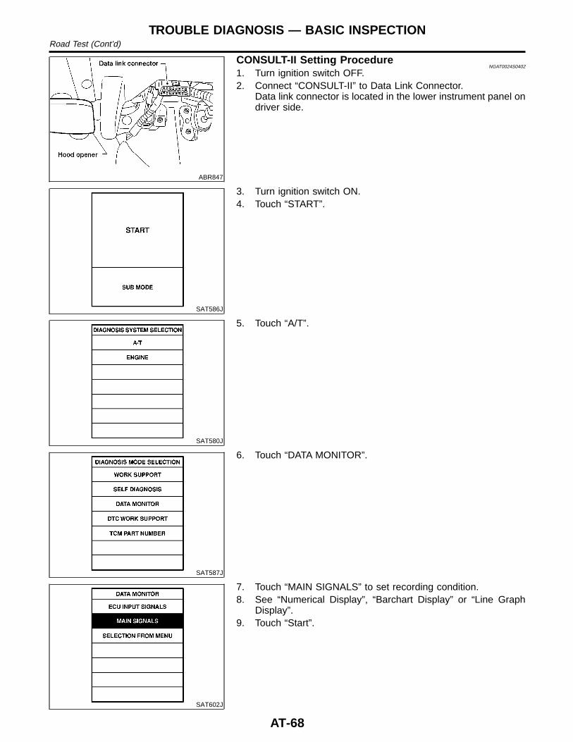
ABR847
CONSULT-II Setting ProcedureNGAT0024S0402
1. Turn ignition switch OFF.2. Connect “CONSULT-II” to Data Link Connector.
Data link connector is located in the lower instrument panel ondriver side.
SAT586J
3. Turn ignition switch ON.4. Touch “START”.
SAT580J
5. Touch “A/T”.
SAT587J
6. Touch “DATA MONITOR”.
SAT602J
7. Touch “MAIN SIGNALS” to set recording condition.8. See “Numerical Display”, “Barchart Display” or “Line Graph
Display”.9. Touch “Start”.
TROUBLE DIAGNOSIS — BASIC INSPECTIONRoad Test (Cont’d)
AT-68
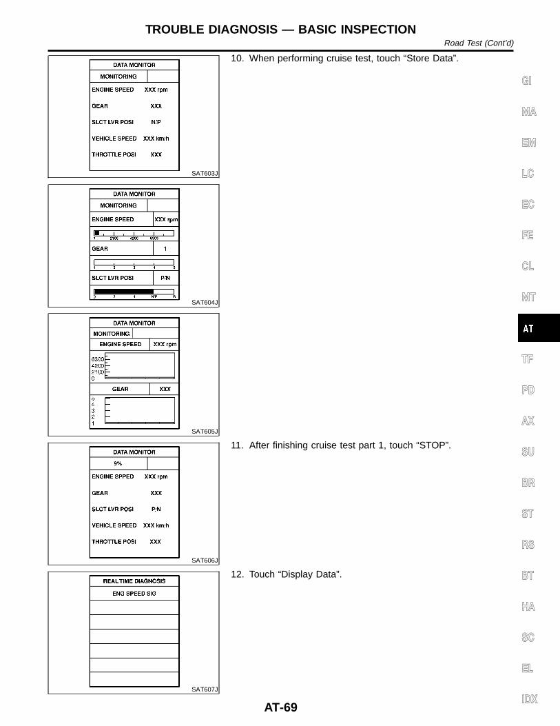
SAT603J
SAT604J
SAT605J
10. When performing cruise test, touch “Store Data”.
SAT606J
11. After finishing cruise test part 1, touch “STOP”.
SAT607J
12. Touch “Display Data”.
GI
MA
EM
LC
EC
FE
CL
MT
TF
PD
AX
SU
BR
ST
RS
BT
HA
SC
EL
IDX
TROUBLE DIAGNOSIS — BASIC INSPECTIONRoad Test (Cont’d)
AT-69
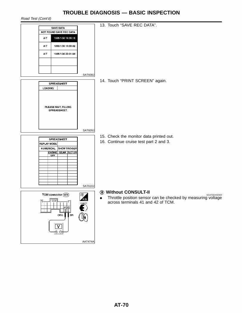
SAT608J
13. Touch “SAVE REC DATA”.
SAT609J
14. Touch “PRINT SCREEN” again.
SAT610J
15. Check the monitor data printed out.16. Continue cruise test part 2 and 3.
AAT474A
Without CONSULT-IINGAT0024S0403
I Throttle position sensor can be checked by measuring voltageacross terminals 41 and 42 of TCM.
TROUBLE DIAGNOSIS — BASIC INSPECTIONRoad Test (Cont’d)
AT-70
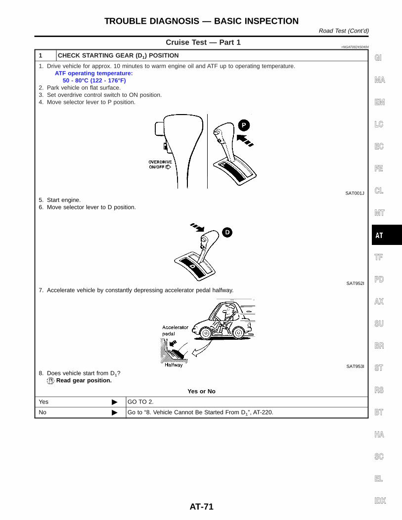
Cruise Test — Part 1=NGAT0024S0404
1 CHECK STARTING GEAR (D 1) POSITION
1. Drive vehicle for approx. 10 minutes to warm engine oil and ATF up to operating temperature.ATF operating temperature:
50 - 80°C (122 - 176°F)2. Park vehicle on flat surface.3. Set overdrive control switch to ON position.4. Move selector lever to P position.
SAT001J
5. Start engine.6. Move selector lever to D position.
SAT952I
7. Accelerate vehicle by constantly depressing accelerator pedal halfway.
SAT953I
8. Does vehicle start from D1?Read gear position.
Yes or No
Yes © GO TO 2.
No © Go to “8. Vehicle Cannot Be Started From D1”, AT-220.
GI
MA
EM
LC
EC
FE
CL
MT
TF
PD
AX
SU
BR
ST
RS
BT
HA
SC
EL
IDX
TROUBLE DIAGNOSIS — BASIC INSPECTIONRoad Test (Cont’d)
AT-71
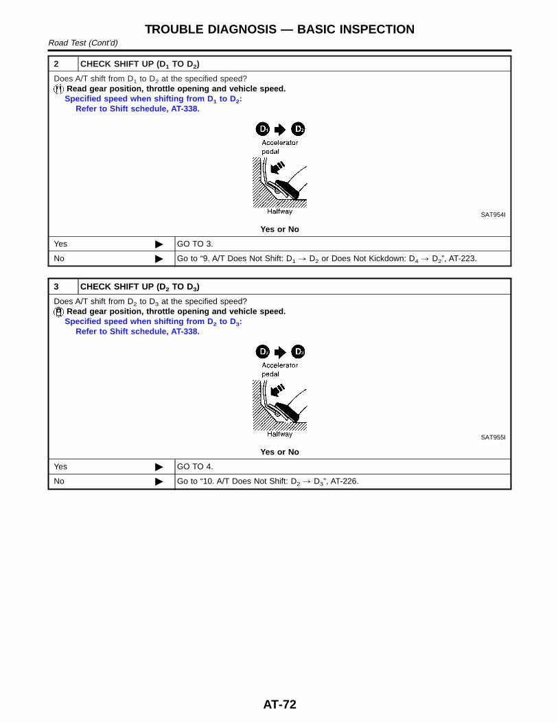
2 CHECK SHIFT UP (D1 TO D2)
Does A/T shift from D1 to D2 at the specified speed?Read gear position, throttle opening and vehicle speed.Specified speed when shifting from D 1 to D2:
Refer to Shift schedule, AT-338.
SAT954I
Yes or No
Yes © GO TO 3.
No © Go to “9. A/T Does Not Shift: D1 , D2 or Does Not Kickdown: D4 , D2”, AT-223.
3 CHECK SHIFT UP (D2 TO D3)
Does A/T shift from D2 to D3 at the specified speed?Read gear position, throttle opening and vehicle speed.Specified speed when shifting from D 2 to D3:
Refer to Shift schedule, AT-338.
SAT955I
Yes or No
Yes © GO TO 4.
No © Go to “10. A/T Does Not Shift: D2 , D3”, AT-226.
TROUBLE DIAGNOSIS — BASIC INSPECTIONRoad Test (Cont’d)
AT-72
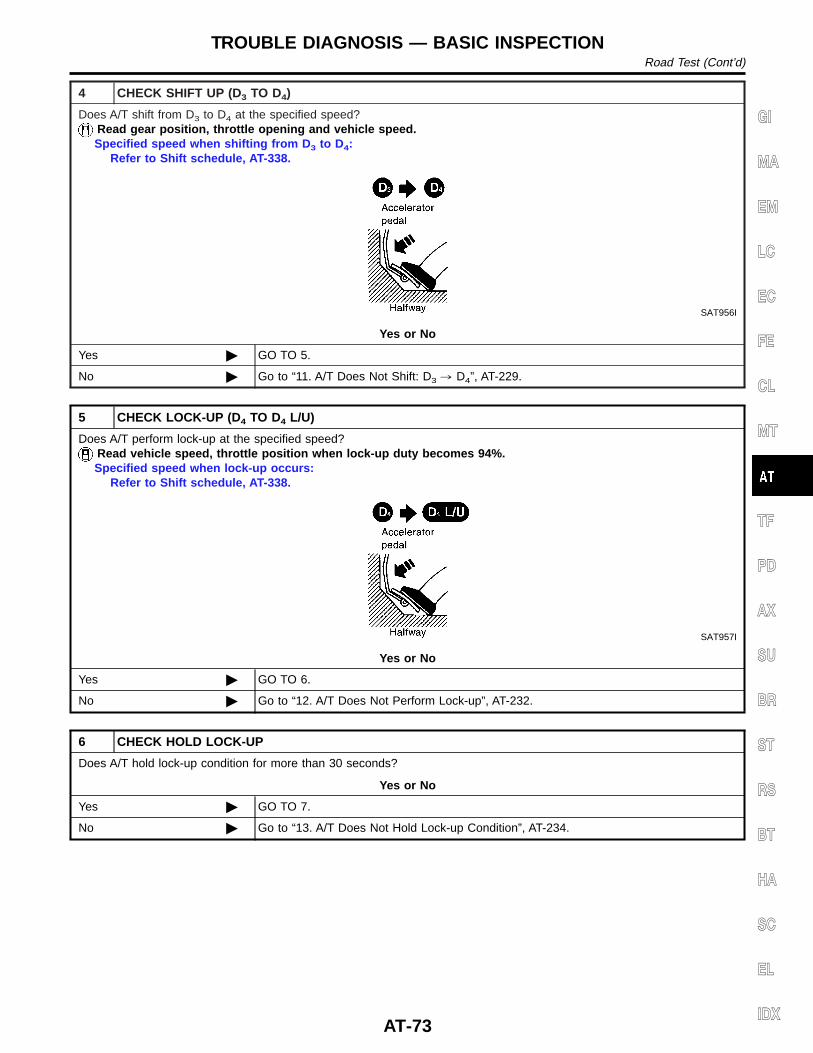
4 CHECK SHIFT UP (D3 TO D4)
Does A/T shift from D3 to D4 at the specified speed?Read gear position, throttle opening and vehicle speed.Specified speed when shifting from D 3 to D4:
Refer to Shift schedule, AT-338.
SAT956I
Yes or No
Yes © GO TO 5.
No © Go to “11. A/T Does Not Shift: D3 , D4”, AT-229.
5 CHECK LOCK-UP (D 4 TO D4 L/U)
Does A/T perform lock-up at the specified speed?Read vehicle speed, throttle position when lock-up duty becomes 94%.Specified speed when lock-up occurs:
Refer to Shift schedule, AT-338.
SAT957I
Yes or No
Yes © GO TO 6.
No © Go to “12. A/T Does Not Perform Lock-up”, AT-232.
6 CHECK HOLD LOCK-UP
Does A/T hold lock-up condition for more than 30 seconds?
Yes or No
Yes © GO TO 7.
No © Go to “13. A/T Does Not Hold Lock-up Condition”, AT-234.
GI
MA
EM
LC
EC
FE
CL
MT
TF
PD
AX
SU
BR
ST
RS
BT
HA
SC
EL
IDX
TROUBLE DIAGNOSIS — BASIC INSPECTIONRoad Test (Cont’d)
AT-73
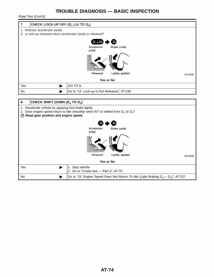
7 CHECK LOCK-UP OFF (D 4 L/U TO D4)
1. Release accelerator pedal.2. Is lock-up released when accelerator pedal is released?
SAT958I
Yes or No
Yes © GO TO 8.
No © Go to “14. Lock-up Is Not Released”, AT-236.
8 CHECK SHIFT DOWN (D4 TO D3)
1. Decelerate vehicle by applying foot brake lightly.2. Does engine speed return to idle smoothly when A/T is shifted from D4 to D3?
Read gear position and engine speed.
SAT959I
Yes or No
Yes © 1. Stop vehicle.2. Go to “Cruise test — Part 2”, AT-75.
No © Go to “15. Engine Speed Does Not Return To Idle (Light Braking D4, D3)”, AT-237.
TROUBLE DIAGNOSIS — BASIC INSPECTIONRoad Test (Cont’d)
AT-74
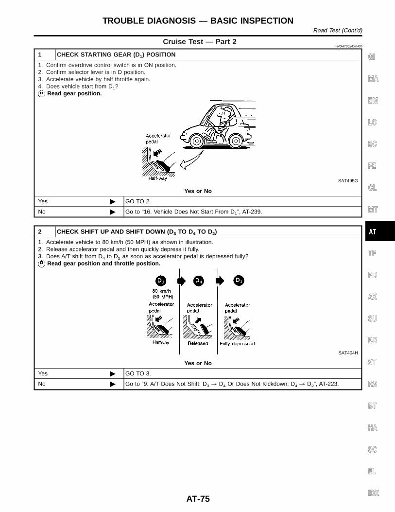
Cruise Test — Part 2=NGAT0024S0405
1 CHECK STARTING GEAR (D 1) POSITION
1. Confirm overdrive control switch is in ON position.2. Confirm selector lever is in D position.3. Accelerate vehicle by half throttle again.4. Does vehicle start from D1?
Read gear position.
SAT495G
Yes or No
Yes © GO TO 2.
No © Go to “16. Vehicle Does Not Start From D1”, AT-239.
2 CHECK SHIFT UP AND SHIFT DOWN (D3 TO D4 TO D2)
1. Accelerate vehicle to 80 km/h (50 MPH) as shown in illustration.2. Release accelerator pedal and then quickly depress it fully.3. Does A/T shift from D4 to D2 as soon as accelerator pedal is depressed fully?
Read gear position and throttle position.
SAT404H
Yes or No
Yes © GO TO 3.
No © Go to “9. A/T Does Not Shift: D3 , D4 Or Does Not Kickdown: D4 , D2”, AT-223.
GI
MA
EM
LC
EC
FE
CL
MT
TF
PD
AX
SU
BR
ST
RS
BT
HA
SC
EL
IDX
TROUBLE DIAGNOSIS — BASIC INSPECTIONRoad Test (Cont’d)
AT-75
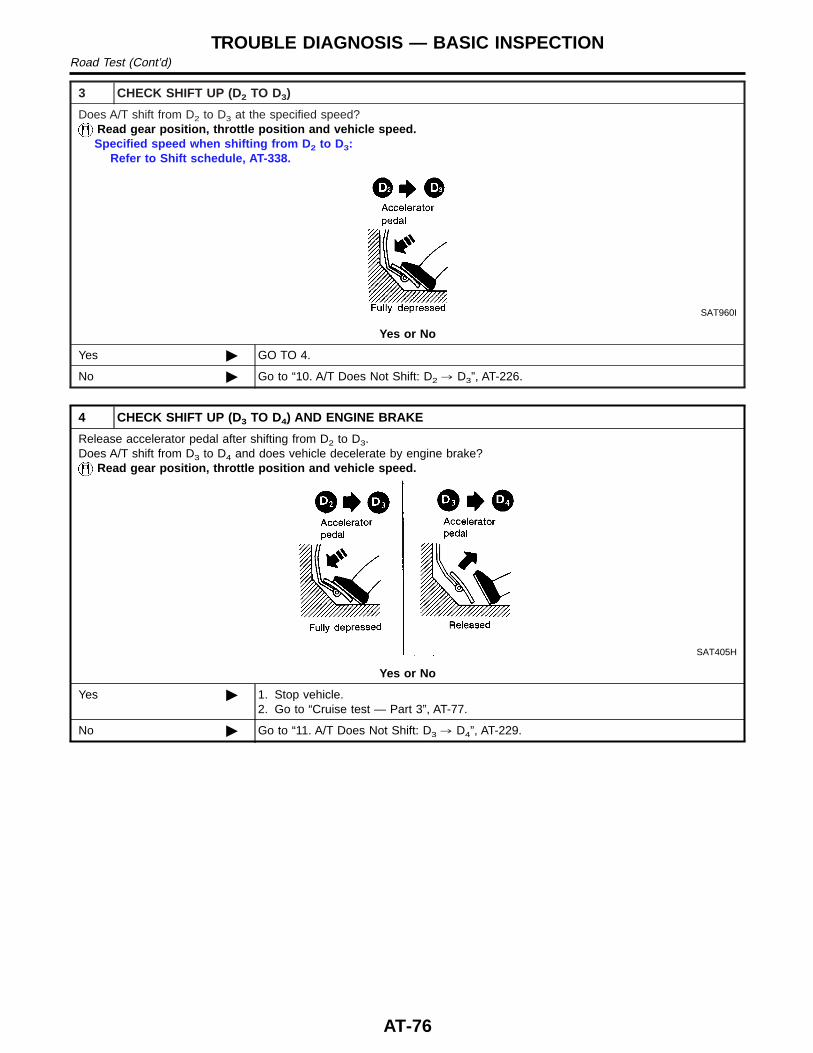
3 CHECK SHIFT UP (D2 TO D3)
Does A/T shift from D2 to D3 at the specified speed?Read gear position, throttle position and vehicle speed.Specified speed when shifting from D 2 to D3:
Refer to Shift schedule, AT-338.
SAT960I
Yes or No
Yes © GO TO 4.
No © Go to “10. A/T Does Not Shift: D2 , D3”, AT-226.
4 CHECK SHIFT UP (D3 TO D4) AND ENGINE BRAKE
Release accelerator pedal after shifting from D2 to D3.Does A/T shift from D3 to D4 and does vehicle decelerate by engine brake?
Read gear position, throttle position and vehicle speed.
SAT405H
Yes or No
Yes © 1. Stop vehicle.2. Go to “Cruise test — Part 3”, AT-77.
No © Go to “11. A/T Does Not Shift: D3 , D4”, AT-229.
TROUBLE DIAGNOSIS — BASIC INSPECTIONRoad Test (Cont’d)
AT-76
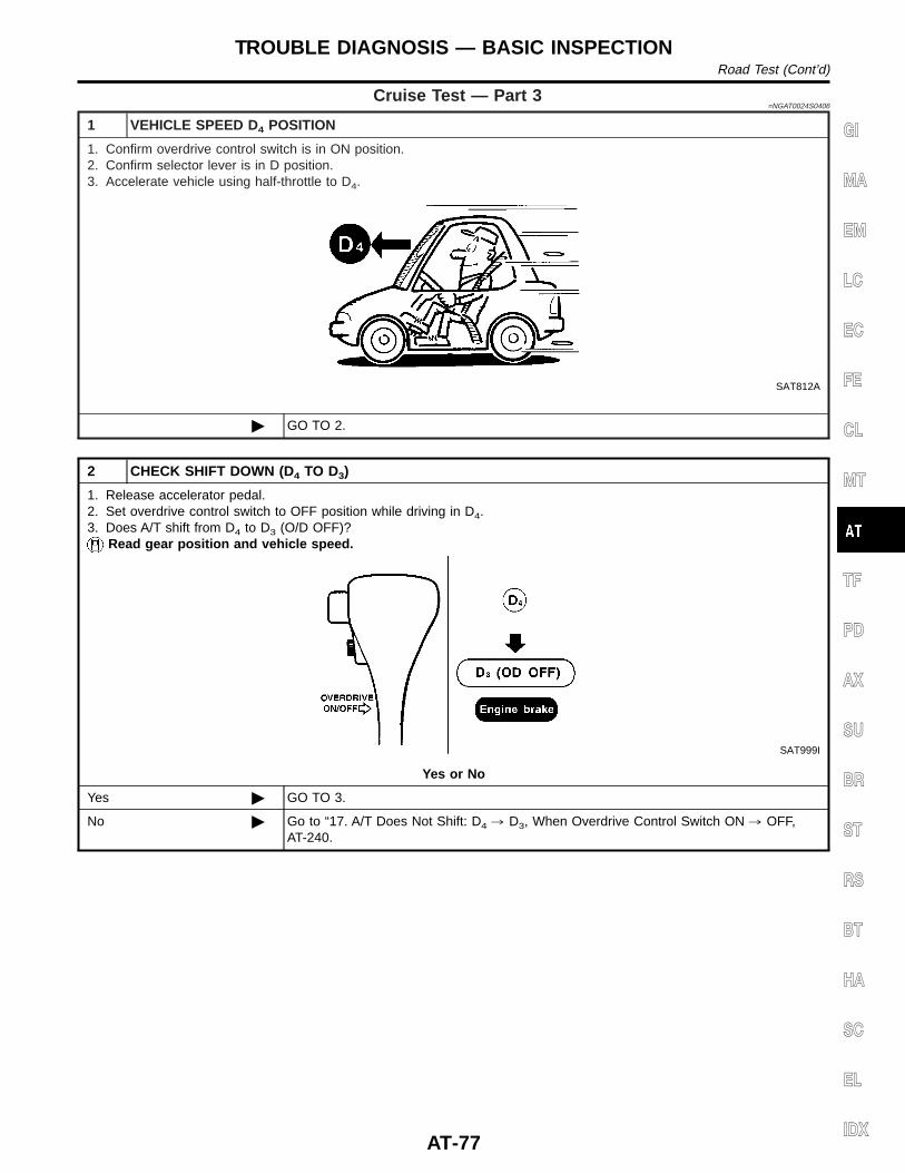
Cruise Test — Part 3=NGAT0024S0406
1 VEHICLE SPEED D4 POSITION
1. Confirm overdrive control switch is in ON position.2. Confirm selector lever is in D position.3. Accelerate vehicle using half-throttle to D4.
SAT812A
© GO TO 2.
2 CHECK SHIFT DOWN (D4 TO D3)
1. Release accelerator pedal.2. Set overdrive control switch to OFF position while driving in D4.3. Does A/T shift from D4 to D3 (O/D OFF)?
Read gear position and vehicle speed.
SAT999I
Yes or No
Yes © GO TO 3.
No © Go to “17. A/T Does Not Shift: D4 , D3, When Overdrive Control Switch ON , OFF,AT-240.
GI
MA
EM
LC
EC
FE
CL
MT
TF
PD
AX
SU
BR
ST
RS
BT
HA
SC
EL
IDX
TROUBLE DIAGNOSIS — BASIC INSPECTIONRoad Test (Cont’d)
AT-77
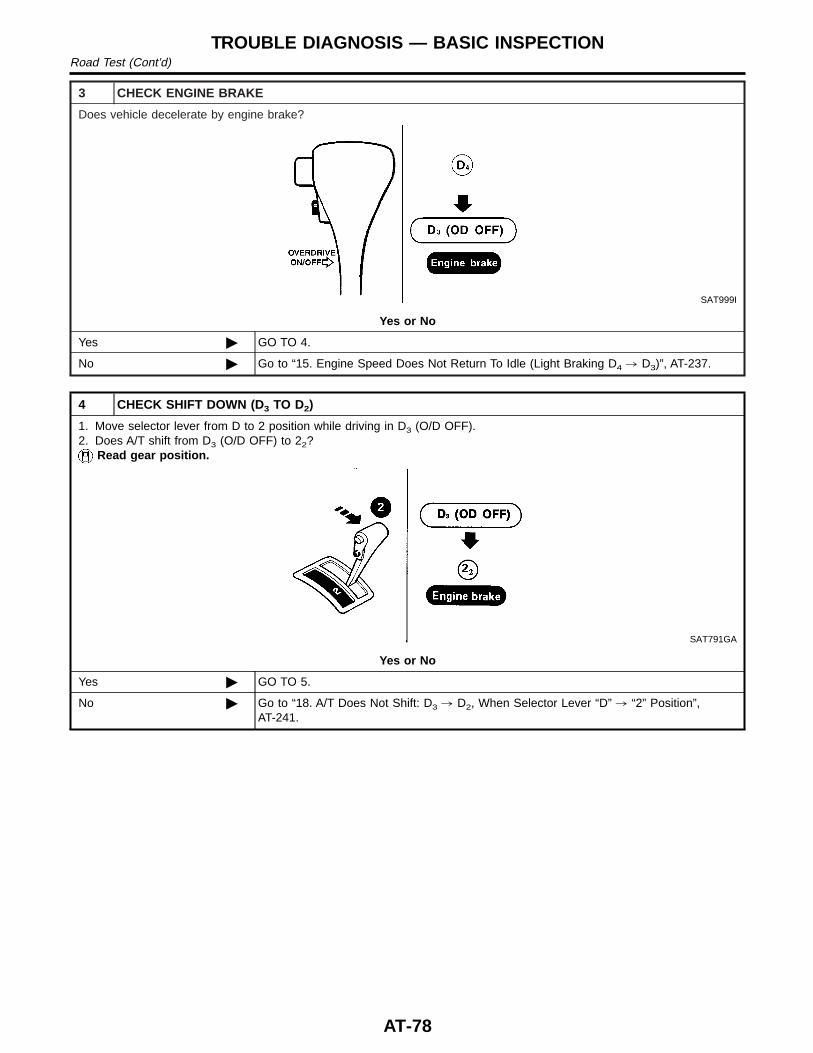
3 CHECK ENGINE BRAKE
Does vehicle decelerate by engine brake?
SAT999I
Yes or No
Yes © GO TO 4.
No © Go to “15. Engine Speed Does Not Return To Idle (Light Braking D4 , D3)”, AT-237.
4 CHECK SHIFT DOWN (D3 TO D2)
1. Move selector lever from D to 2 position while driving in D3 (O/D OFF).2. Does A/T shift from D3 (O/D OFF) to 22?
Read gear position.
SAT791GA
Yes or No
Yes © GO TO 5.
No © Go to “18. A/T Does Not Shift: D3 , D2, When Selector Lever “D” , “2” Position”,AT-241.
TROUBLE DIAGNOSIS — BASIC INSPECTIONRoad Test (Cont’d)
AT-78
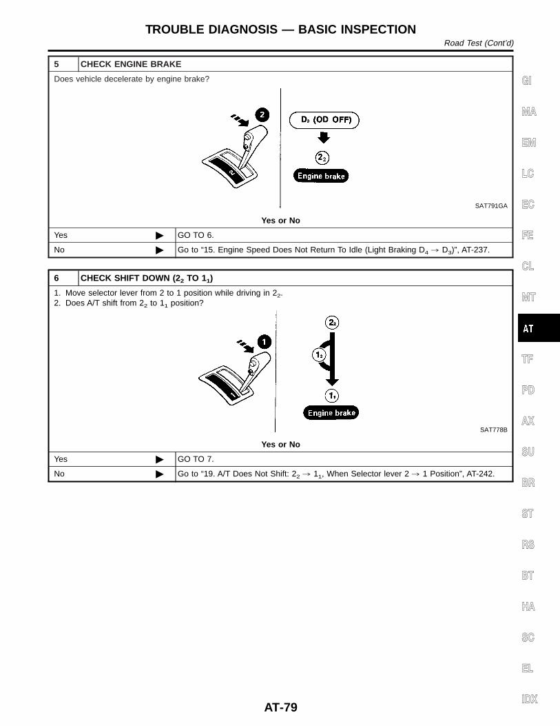
5 CHECK ENGINE BRAKE
Does vehicle decelerate by engine brake?
SAT791GA
Yes or No
Yes © GO TO 6.
No © Go to “15. Engine Speed Does Not Return To Idle (Light Braking D4 , D3)”, AT-237.
6 CHECK SHIFT DOWN (22 TO 11)
1. Move selector lever from 2 to 1 position while driving in 22.2. Does A/T shift from 22 to 11 position?
SAT778B
Yes or No
Yes © GO TO 7.
No © Go to “19. A/T Does Not Shift: 22 , 11, When Selector lever 2 , 1 Position”, AT-242.
GI
MA
EM
LC
EC
FE
CL
MT
TF
PD
AX
SU
BR
ST
RS
BT
HA
SC
EL
IDX
TROUBLE DIAGNOSIS — BASIC INSPECTIONRoad Test (Cont’d)
AT-79
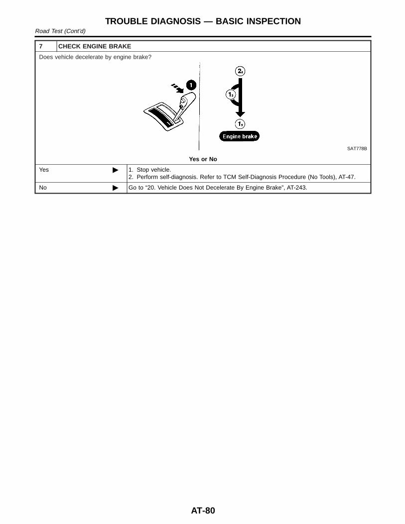
7 CHECK ENGINE BRAKE
Does vehicle decelerate by engine brake?
SAT778B
Yes or No
Yes © 1. Stop vehicle.2. Perform self-diagnosis. Refer to TCM Self-Diagnosis Procedure (No Tools), AT-47.
No © Go to “20. Vehicle Does Not Decelerate By Engine Brake”, AT-243.
TROUBLE DIAGNOSIS — BASIC INSPECTIONRoad Test (Cont’d)
AT-80
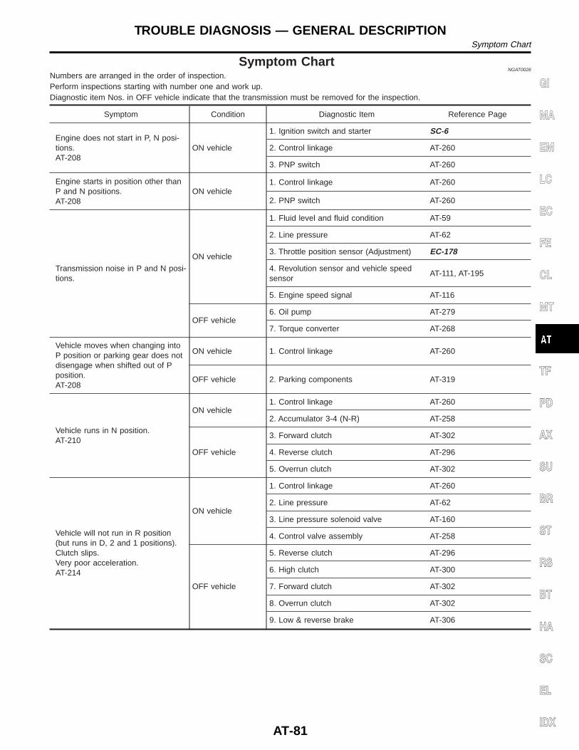
Symptom ChartNGAT0026
Numbers are arranged in the order of inspection.Perform inspections starting with number one and work up.Diagnostic item Nos. in OFF vehicle indicate that the transmission must be removed for the inspection.
Symptom Condition Diagnostic Item Reference Page
Engine does not start in P, N posi-tions.AT-208
ON vehicle
1. Ignition switch and starter SC-6
2. Control linkage AT-260
3. PNP switch AT-260
Engine starts in position other thanP and N positions.AT-208
ON vehicle1. Control linkage AT-260
2. PNP switch AT-260
Transmission noise in P and N posi-tions.
ON vehicle
1. Fluid level and fluid condition AT-59
2. Line pressure AT-62
3. Throttle position sensor (Adjustment) EC-178
4. Revolution sensor and vehicle speedsensor
AT-111, AT-195
5. Engine speed signal AT-116
OFF vehicle6. Oil pump AT-279
7. Torque converter AT-268
Vehicle moves when changing intoP position or parking gear does notdisengage when shifted out of Pposition.AT-208
ON vehicle 1. Control linkage AT-260
OFF vehicle 2. Parking components AT-319
Vehicle runs in N position.AT-210
ON vehicle1. Control linkage AT-260
2. Accumulator 3-4 (N-R) AT-258
OFF vehicle
3. Forward clutch AT-302
4. Reverse clutch AT-296
5. Overrun clutch AT-302
Vehicle will not run in R position(but runs in D, 2 and 1 positions).Clutch slips.Very poor acceleration.AT-214
ON vehicle
1. Control linkage AT-260
2. Line pressure AT-62
3. Line pressure solenoid valve AT-160
4. Control valve assembly AT-258
OFF vehicle
5. Reverse clutch AT-296
6. High clutch AT-300
7. Forward clutch AT-302
8. Overrun clutch AT-302
9. Low & reverse brake AT-306
GI
MA
EM
LC
EC
FE
CL
MT
TF
PD
AX
SU
BR
ST
RS
BT
HA
SC
EL
IDX
TROUBLE DIAGNOSIS — GENERAL DESCRIPTIONSymptom Chart
AT-81
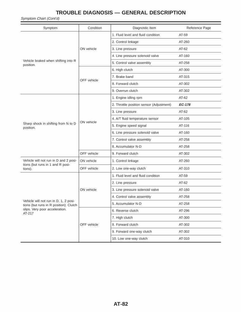
Symptom Condition Diagnostic Item Reference Page
Vehicle braked when shifting into Rposition.
ON vehicle
1. Fluid level and fluid condition AT-59
2. Control linkage AT-260
3. Line pressure AT-62
4. Line pressure solenoid valve AT-160
5. Control valve assembly AT-258
OFF vehicle
6. High clutch AT-300
7. Brake band AT-315
8. Forward clutch AT-302
9. Overrun clutch AT-302
Sharp shock in shifting from N to Dposition.
ON vehicle
1. Engine idling rpm AT-62
2. Throttle position sensor (Adjustment) EC-178
3. Line pressure AT-62
4. A/T fluid temperature sensor AT-105
5. Engine speed signal AT-116
6. Line pressure solenoid valve AT-160
7. Control valve assembly AT-258
8. Accumulator N-D AT-258
OFF vehicle 9. Forward clutch AT-302
Vehicle will not run in D and 2 posi-tions (but runs in 1 and R posi-tions).
ON vehicle 1. Control linkage AT-260
OFF vehicle 2. Low one-way clutch AT-310
Vehicle will not run in D, 1, 2 posi-tions (but runs in R position). Clutchslips. Very poor acceleration.AT-217
ON vehicle
1. Fluid level and fluid condition AT-59
2. Line pressure AT-62
3. Line pressure solenoid valve AT-160
4. Control valve assembly AT-258
5. Accumulator N-D AT-258
OFF vehicle
6. Reverse clutch AT-296
7. High clutch AT-300
8. Forward clutch AT-302
9. Forward one-way clutch AT-302
10. Low one-way clutch AT-310
TROUBLE DIAGNOSIS — GENERAL DESCRIPTIONSymptom Chart (Cont’d)
AT-82

Symptom Condition Diagnostic Item Reference Page
Clutches or brakes slip somewhat instarting.
ON vehicle
1. Fluid level and fluid condition AT-59
2. Control linkage AT-260
3. Throttle position sensor (Adjustment) EC-178
4. Line pressure AT-62
5. Line pressure solenoid valve AT-160
6. Control valve assembly AT-258
7. Accumulator N-D AT-258
8. Accumulator 3-4 (N-R) AT-258
OFF vehicle
9. Forward clutch AT-302
10. Reverse clutch AT-296
11. Low & reverse brake AT-306
12. Oil pump AT-279
13. Torque converter AT-268
Excessive creep. ON vehicle 1. Engine idling rpm EC-614
No creep at all.AT-214, AT-217
ON vehicle
1. Fluid level and fluid condition AT-59
2. Line pressure AT-62
3. Control valve assembly AT-258
OFF vehicle
4. Forward clutch AT-302
5. Oil pump AT-279
6. Torque converter AT-268
Failure to change gear from D1 toD2.
ON vehicle
1. PNP switch AT-260
2. Control linkage AT-260
3. Shift solenoid valve A AT-165
4. Control valve assembly AT-258
5. Revolution sensor and speed sensor AT-111, AT-195
OFF vehicle 6. Brake band AT-315
Failure to change gear from D2 toD3.
ON vehicle
1. PNP switch AT-260
2. Control linkage AT-260
3. Shift solenoid valve B AT-170
4. Control valve assembly AT-258
5. Revolution sensor and speed sensor AT-105, AT-195
OFF vehicle6. High clutch AT-300
7. Brake band AT-315
GI
MA
EM
LC
EC
FE
CL
MT
TF
PD
AX
SU
BR
ST
RS
BT
HA
SC
EL
IDX
TROUBLE DIAGNOSIS — GENERAL DESCRIPTIONSymptom Chart (Cont’d)
AT-83
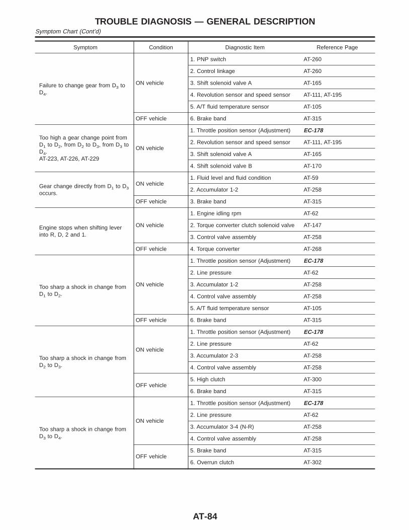
Symptom Condition Diagnostic Item Reference Page
Failure to change gear from D3 toD4.
ON vehicle
1. PNP switch AT-260
2. Control linkage AT-260
3. Shift solenoid valve A AT-165
4. Revolution sensor and speed sensor AT-111, AT-195
5. A/T fluid temperature sensor AT-105
OFF vehicle 6. Brake band AT-315
Too high a gear change point fromD1 to D2, from D2 to D3, from D3 toD4.AT-223, AT-226, AT-229
ON vehicle
1. Throttle position sensor (Adjustment) EC-178
2. Revolution sensor and speed sensor AT-111, AT-195
3. Shift solenoid valve A AT-165
4. Shift solenoid valve B AT-170
Gear change directly from D1 to D3
occurs.
ON vehicle1. Fluid level and fluid condition AT-59
2. Accumulator 1-2 AT-258
OFF vehicle 3. Brake band AT-315
Engine stops when shifting leverinto R, D, 2 and 1.
ON vehicle
1. Engine idling rpm AT-62
2. Torque converter clutch solenoid valve AT-147
3. Control valve assembly AT-258
OFF vehicle 4. Torque converter AT-268
Too sharp a shock in change fromD1 to D2.
ON vehicle
1. Throttle position sensor (Adjustment) EC-178
2. Line pressure AT-62
3. Accumulator 1-2 AT-258
4. Control valve assembly AT-258
5. A/T fluid temperature sensor AT-105
OFF vehicle 6. Brake band AT-315
Too sharp a shock in change fromD2 to D3.
ON vehicle
1. Throttle position sensor (Adjustment) EC-178
2. Line pressure AT-62
3. Accumulator 2-3 AT-258
4. Control valve assembly AT-258
OFF vehicle5. High clutch AT-300
6. Brake band AT-315
Too sharp a shock in change fromD3 to D4.
ON vehicle
1. Throttle position sensor (Adjustment) EC-178
2. Line pressure AT-62
3. Accumulator 3-4 (N-R) AT-258
4. Control valve assembly AT-258
OFF vehicle5. Brake band AT-315
6. Overrun clutch AT-302
TROUBLE DIAGNOSIS — GENERAL DESCRIPTIONSymptom Chart (Cont’d)
AT-84
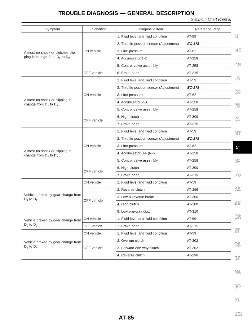
Symptom Condition Diagnostic Item Reference Page
Almost no shock or clutches slip-ping in change from D1 to D2.
ON vehicle
1. Fluid level and fluid condition AT-59
2. Throttle position sensor (Adjustment) EC-178
3. Line pressure AT-62
4. Accumulator 1-2 AT-258
5. Control valve assembly AT-258
OFF vehicle 6. Brake band AT-315
Almost no shock or slipping inchange from D2 to D3 .
ON vehicle
1. Fluid level and fluid condition AT-59
2. Throttle position sensor (Adjustment) EC-178
3. Line pressure AT-62
4. Accumulator 2-3 AT-258
5. Control valve assembly AT-258
OFF vehicle6. High clutch AT-300
7. Brake band AT-315
Almost no shock or slipping inchange from D3 to D4 .
ON vehicle
1. Fluid level and fluid condition AT-59
2. Throttle position sensor (Adjustment) EC-178
3. Line pressure AT-62
4. Accumulator 3-4 (N-R) AT-258
5. Control valve assembly AT-258
OFF vehicle6. High clutch AT-300
7. Brake band AT-315
Vehicle braked by gear change fromD1 to D2.
ON vehicle 1. Fluid level and fluid condition AT-59
OFF vehicle
2. Reverse clutch AT-296
3. Low & reverse brake AT-306
4. High clutch AT-300
5. Low one-way clutch AT-310
Vehicle braked by gear change fromD2 to D3.
ON vehicle 1. Fluid level and fluid condition AT-59
OFF vehicle 2. Brake band AT-315
Vehicle braked by gear change fromD3 to D4.
ON vehicle 1. Fluid level and fluid condition AT-59
OFF vehicle
2. Overrun clutch AT-302
3. Forward one-way clutch AT-302
4. Reverse clutch AT-296
GI
MA
EM
LC
EC
FE
CL
MT
TF
PD
AX
SU
BR
ST
RS
BT
HA
SC
EL
IDX
TROUBLE DIAGNOSIS — GENERAL DESCRIPTIONSymptom Chart (Cont’d)
AT-85
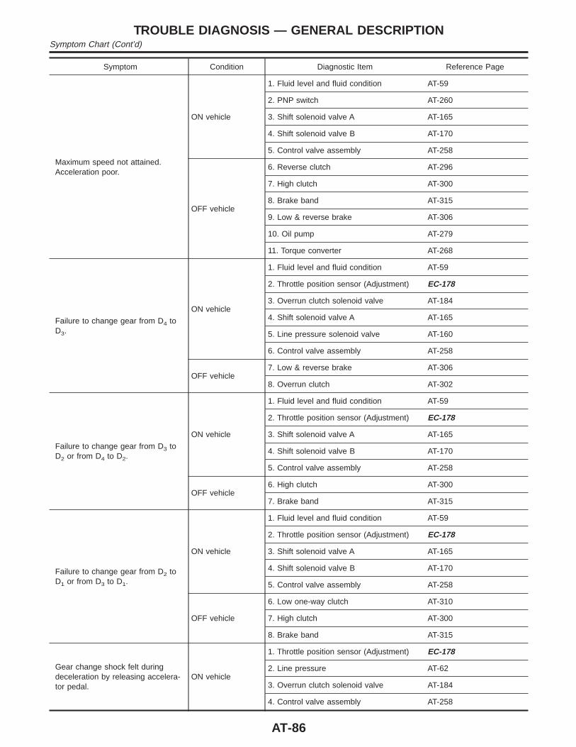
Symptom Condition Diagnostic Item Reference Page
Maximum speed not attained.Acceleration poor.
ON vehicle
1. Fluid level and fluid condition AT-59
2. PNP switch AT-260
3. Shift solenoid valve A AT-165
4. Shift solenoid valve B AT-170
5. Control valve assembly AT-258
OFF vehicle
6. Reverse clutch AT-296
7. High clutch AT-300
8. Brake band AT-315
9. Low & reverse brake AT-306
10. Oil pump AT-279
11. Torque converter AT-268
Failure to change gear from D4 toD3.
ON vehicle
1. Fluid level and fluid condition AT-59
2. Throttle position sensor (Adjustment) EC-178
3. Overrun clutch solenoid valve AT-184
4. Shift solenoid valve A AT-165
5. Line pressure solenoid valve AT-160
6. Control valve assembly AT-258
OFF vehicle7. Low & reverse brake AT-306
8. Overrun clutch AT-302
Failure to change gear from D3 toD2 or from D4 to D2.
ON vehicle
1. Fluid level and fluid condition AT-59
2. Throttle position sensor (Adjustment) EC-178
3. Shift solenoid valve A AT-165
4. Shift solenoid valve B AT-170
5. Control valve assembly AT-258
OFF vehicle6. High clutch AT-300
7. Brake band AT-315
Failure to change gear from D2 toD1 or from D3 to D1.
ON vehicle
1. Fluid level and fluid condition AT-59
2. Throttle position sensor (Adjustment) EC-178
3. Shift solenoid valve A AT-165
4. Shift solenoid valve B AT-170
5. Control valve assembly AT-258
OFF vehicle
6. Low one-way clutch AT-310
7. High clutch AT-300
8. Brake band AT-315
Gear change shock felt duringdeceleration by releasing accelera-tor pedal.
ON vehicle
1. Throttle position sensor (Adjustment) EC-178
2. Line pressure AT-62
3. Overrun clutch solenoid valve AT-184
4. Control valve assembly AT-258
TROUBLE DIAGNOSIS — GENERAL DESCRIPTIONSymptom Chart (Cont’d)
AT-86
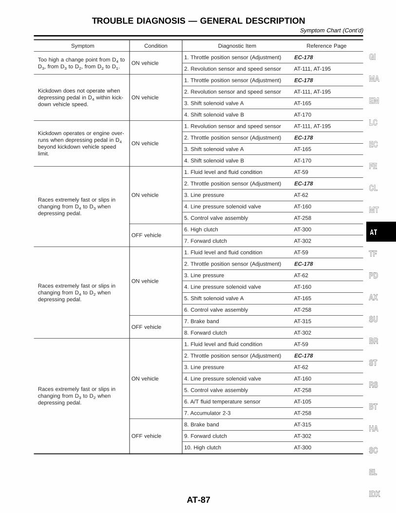
Symptom Condition Diagnostic Item Reference Page
Too high a change point from D4 toD3, from D3 to D2, from D2 to D1.
ON vehicle1. Throttle position sensor (Adjustment) EC-178
2. Revolution sensor and speed sensor AT-111, AT-195
Kickdown does not operate whendepressing pedal in D4 within kick-down vehicle speed.
ON vehicle
1. Throttle position sensor (Adjustment) EC-178
2. Revolution sensor and speed sensor AT-111, AT-195
3. Shift solenoid valve A AT-165
4. Shift solenoid valve B AT-170
Kickdown operates or engine over-runs when depressing pedal in D4
beyond kickdown vehicle speedlimit.
ON vehicle
1. Revolution sensor and speed sensor AT-111, AT-195
2. Throttle position sensor (Adjustment) EC-178
3. Shift solenoid valve A AT-165
4. Shift solenoid valve B AT-170
Races extremely fast or slips inchanging from D4 to D3 whendepressing pedal.
ON vehicle
1. Fluid level and fluid condition AT-59
2. Throttle position sensor (Adjustment) EC-178
3. Line pressure AT-62
4. Line pressure solenoid valve AT-160
5. Control valve assembly AT-258
OFF vehicle6. High clutch AT-300
7. Forward clutch AT-302
Races extremely fast or slips inchanging from D4 to D2 whendepressing pedal.
ON vehicle
1. Fluid level and fluid condition AT-59
2. Throttle position sensor (Adjustment) EC-178
3. Line pressure AT-62
4. Line pressure solenoid valve AT-160
5. Shift solenoid valve A AT-165
6. Control valve assembly AT-258
OFF vehicle7. Brake band AT-315
8. Forward clutch AT-302
Races extremely fast or slips inchanging from D3 to D2 whendepressing pedal.
ON vehicle
1. Fluid level and fluid condition AT-59
2. Throttle position sensor (Adjustment) EC-178
3. Line pressure AT-62
4. Line pressure solenoid valve AT-160
5. Control valve assembly AT-258
6. A/T fluid temperature sensor AT-105
7. Accumulator 2-3 AT-258
OFF vehicle
8. Brake band AT-315
9. Forward clutch AT-302
10. High clutch AT-300
GI
MA
EM
LC
EC
FE
CL
MT
TF
PD
AX
SU
BR
ST
RS
BT
HA
SC
EL
IDX
TROUBLE DIAGNOSIS — GENERAL DESCRIPTIONSymptom Chart (Cont’d)
AT-87
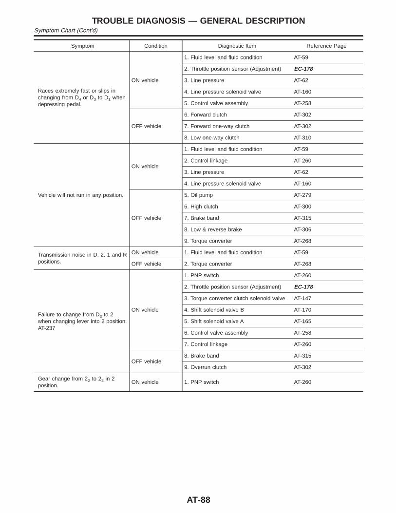
Symptom Condition Diagnostic Item Reference Page
Races extremely fast or slips inchanging from D4 or D3 to D1 whendepressing pedal.
ON vehicle
1. Fluid level and fluid condition AT-59
2. Throttle position sensor (Adjustment) EC-178
3. Line pressure AT-62
4. Line pressure solenoid valve AT-160
5. Control valve assembly AT-258
OFF vehicle
6. Forward clutch AT-302
7. Forward one-way clutch AT-302
8. Low one-way clutch AT-310
Vehicle will not run in any position.
ON vehicle
1. Fluid level and fluid condition AT-59
2. Control linkage AT-260
3. Line pressure AT-62
4. Line pressure solenoid valve AT-160
OFF vehicle
5. Oil pump AT-279
6. High clutch AT-300
7. Brake band AT-315
8. Low & reverse brake AT-306
9. Torque converter AT-268
Transmission noise in D, 2, 1 and Rpositions.
ON vehicle 1. Fluid level and fluid condition AT-59
OFF vehicle 2. Torque converter AT-268
Failure to change from D3 to 2when changing lever into 2 position.AT-237
ON vehicle
1. PNP switch AT-260
2. Throttle position sensor (Adjustment) EC-178
3. Torque converter clutch solenoid valve AT-147
4. Shift solenoid valve B AT-170
5. Shift solenoid valve A AT-165
6. Control valve assembly AT-258
7. Control linkage AT-260
OFF vehicle8. Brake band AT-315
9. Overrun clutch AT-302
Gear change from 22 to 23 in 2position.
ON vehicle 1. PNP switch AT-260
TROUBLE DIAGNOSIS — GENERAL DESCRIPTIONSymptom Chart (Cont’d)
AT-88
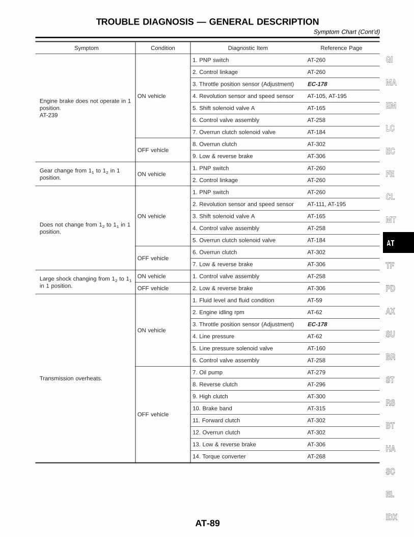
Symptom Condition Diagnostic Item Reference Page
Engine brake does not operate in 1position.AT-239
ON vehicle
1. PNP switch AT-260
2. Control linkage AT-260
3. Throttle position sensor (Adjustment) EC-178
4. Revolution sensor and speed sensor AT-105, AT-195
5. Shift solenoid valve A AT-165
6. Control valve assembly AT-258
7. Overrun clutch solenoid valve AT-184
OFF vehicle8. Overrun clutch AT-302
9. Low & reverse brake AT-306
Gear change from 11 to 12 in 1position.
ON vehicle1. PNP switch AT-260
2. Control linkage AT-260
Does not change from 12 to 11 in 1position.
ON vehicle
1. PNP switch AT-260
2. Revolution sensor and speed sensor AT-111, AT-195
3. Shift solenoid valve A AT-165
4. Control valve assembly AT-258
5. Overrun clutch solenoid valve AT-184
OFF vehicle6. Overrun clutch AT-302
7. Low & reverse brake AT-306
Large shock changing from 12 to 11
in 1 position.
ON vehicle 1. Control valve assembly AT-258
OFF vehicle 2. Low & reverse brake AT-306
Transmission overheats.
ON vehicle
1. Fluid level and fluid condition AT-59
2. Engine idling rpm AT-62
3. Throttle position sensor (Adjustment) EC-178
4. Line pressure AT-62
5. Line pressure solenoid valve AT-160
6. Control valve assembly AT-258
OFF vehicle
7. Oil pump AT-279
8. Reverse clutch AT-296
9. High clutch AT-300
10. Brake band AT-315
11. Forward clutch AT-302
12. Overrun clutch AT-302
13. Low & reverse brake AT-306
14. Torque converter AT-268
GI
MA
EM
LC
EC
FE
CL
MT
TF
PD
AX
SU
BR
ST
RS
BT
HA
SC
EL
IDX
TROUBLE DIAGNOSIS — GENERAL DESCRIPTIONSymptom Chart (Cont’d)
AT-89
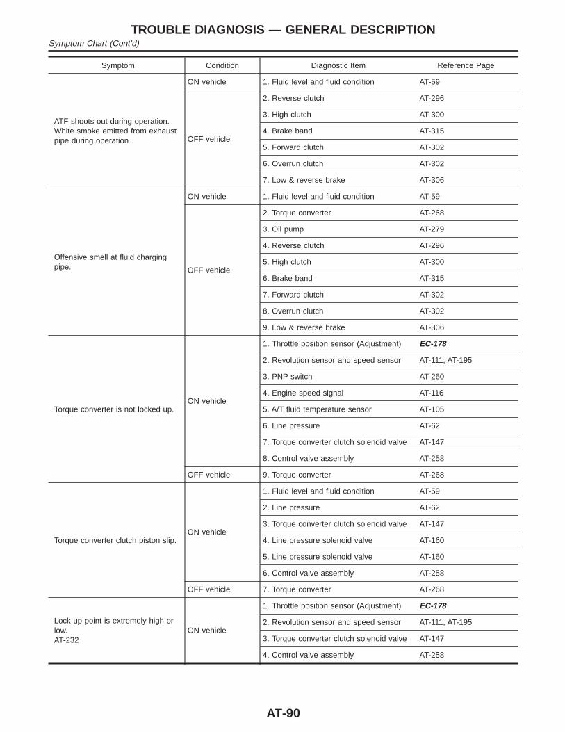
Symptom Condition Diagnostic Item Reference Page
ATF shoots out during operation.White smoke emitted from exhaustpipe during operation.
ON vehicle 1. Fluid level and fluid condition AT-59
OFF vehicle
2. Reverse clutch AT-296
3. High clutch AT-300
4. Brake band AT-315
5. Forward clutch AT-302
6. Overrun clutch AT-302
7. Low & reverse brake AT-306
Offensive smell at fluid chargingpipe.
ON vehicle 1. Fluid level and fluid condition AT-59
OFF vehicle
2. Torque converter AT-268
3. Oil pump AT-279
4. Reverse clutch AT-296
5. High clutch AT-300
6. Brake band AT-315
7. Forward clutch AT-302
8. Overrun clutch AT-302
9. Low & reverse brake AT-306
Torque converter is not locked up.ON vehicle
1. Throttle position sensor (Adjustment) EC-178
2. Revolution sensor and speed sensor AT-111, AT-195
3. PNP switch AT-260
4. Engine speed signal AT-116
5. A/T fluid temperature sensor AT-105
6. Line pressure AT-62
7. Torque converter clutch solenoid valve AT-147
8. Control valve assembly AT-258
OFF vehicle 9. Torque converter AT-268
Torque converter clutch piston slip.ON vehicle
1. Fluid level and fluid condition AT-59
2. Line pressure AT-62
3. Torque converter clutch solenoid valve AT-147
4. Line pressure solenoid valve AT-160
5. Line pressure solenoid valve AT-160
6. Control valve assembly AT-258
OFF vehicle 7. Torque converter AT-268
Lock-up point is extremely high orlow.AT-232
ON vehicle
1. Throttle position sensor (Adjustment) EC-178
2. Revolution sensor and speed sensor AT-111, AT-195
3. Torque converter clutch solenoid valve AT-147
4. Control valve assembly AT-258
TROUBLE DIAGNOSIS — GENERAL DESCRIPTIONSymptom Chart (Cont’d)
AT-90
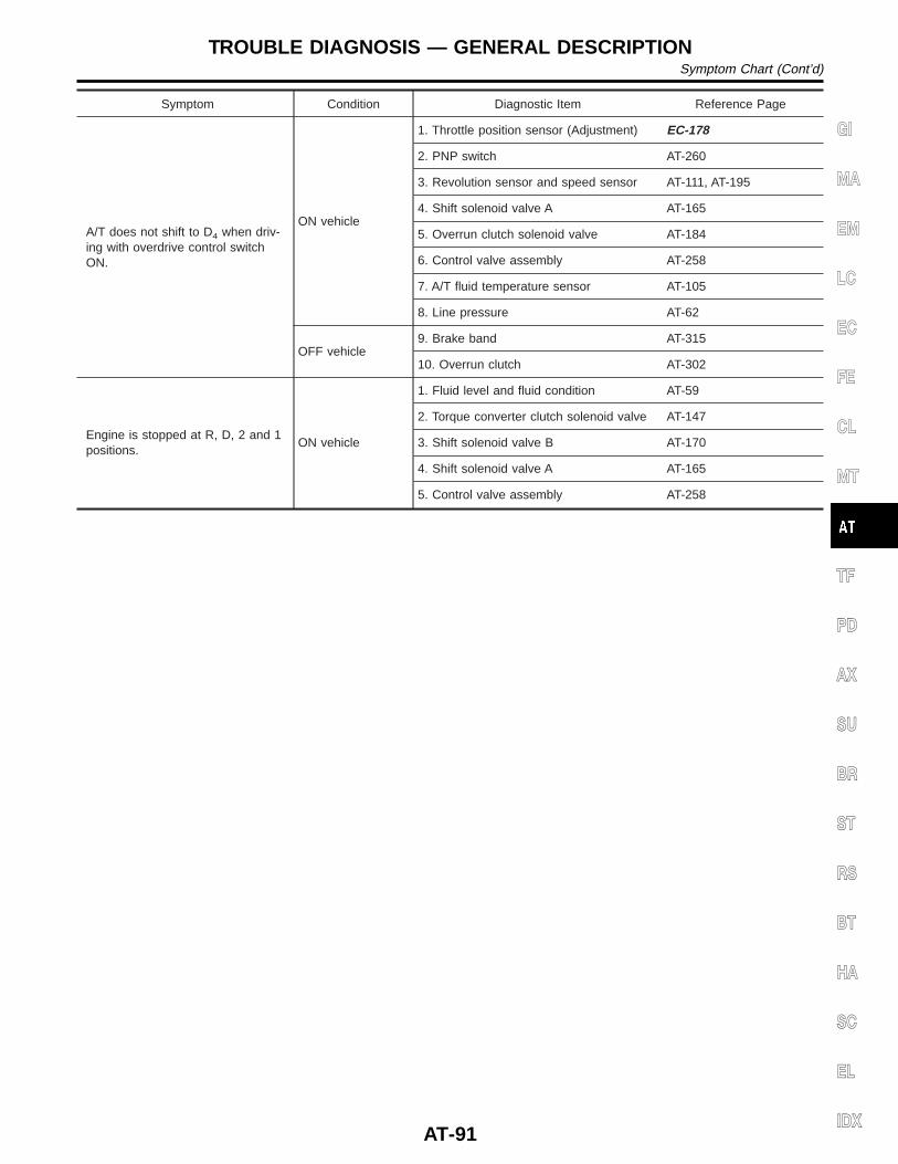
Symptom Condition Diagnostic Item Reference Page
A/T does not shift to D4 when driv-ing with overdrive control switchON.
ON vehicle
1. Throttle position sensor (Adjustment) EC-178
2. PNP switch AT-260
3. Revolution sensor and speed sensor AT-111, AT-195
4. Shift solenoid valve A AT-165
5. Overrun clutch solenoid valve AT-184
6. Control valve assembly AT-258
7. A/T fluid temperature sensor AT-105
8. Line pressure AT-62
OFF vehicle9. Brake band AT-315
10. Overrun clutch AT-302
Engine is stopped at R, D, 2 and 1positions.
ON vehicle
1. Fluid level and fluid condition AT-59
2. Torque converter clutch solenoid valve AT-147
3. Shift solenoid valve B AT-170
4. Shift solenoid valve A AT-165
5. Control valve assembly AT-258
GI
MA
EM
LC
EC
FE
CL
MT
TF
PD
AX
SU
BR
ST
RS
BT
HA
SC
EL
IDX
TROUBLE DIAGNOSIS — GENERAL DESCRIPTIONSymptom Chart (Cont’d)
AT-91
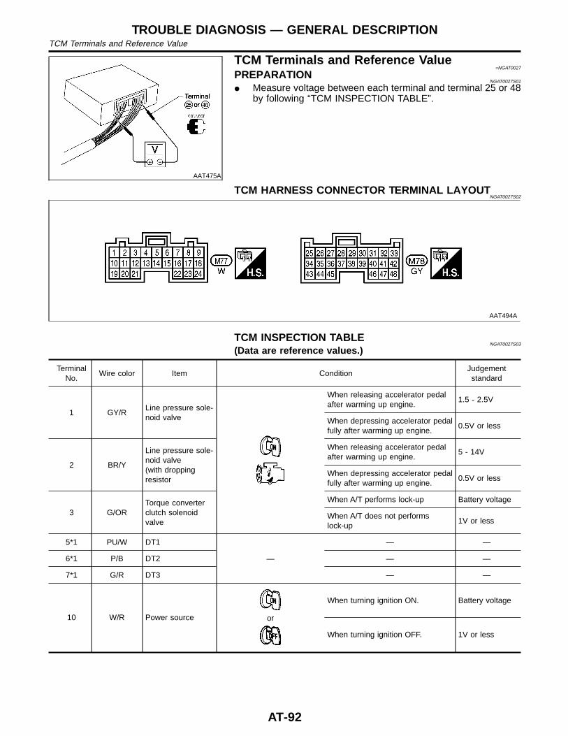
AAT475A
TCM Terminals and Reference Value=NGAT0027
PREPARATIONNGAT0027S01
I Measure voltage between each terminal and terminal 25 or 48by following “TCM INSPECTION TABLE”.
TCM HARNESS CONNECTOR TERMINAL LAYOUTNGAT0027S02
AAT494A
TCM INSPECTION TABLENGAT0027S03
(Data are reference values.)
TerminalNo.
Wire color Item ConditionJudgementstandard
1 GY/RLine pressure sole-noid valve
When releasing accelerator pedalafter warming up engine.
1.5 - 2.5V
When depressing accelerator pedalfully after warming up engine.
0.5V or less
2 BR/Y
Line pressure sole-noid valve(with droppingresistor
When releasing accelerator pedalafter warming up engine.
5 - 14V
When depressing accelerator pedalfully after warming up engine.
0.5V or less
3 G/ORTorque converterclutch solenoidvalve
When A/T performs lock-up Battery voltage
When A/T does not performslock-up
1V or less
5*1 PU/W DT1
—
— —
6*1 P/B DT2 — —
7*1 G/R DT3 — —
10 W/R Power source or
When turning ignition ON. Battery voltage
When turning ignition OFF. 1V or less
TROUBLE DIAGNOSIS — GENERAL DESCRIPTIONTCM Terminals and Reference Value
AT-92
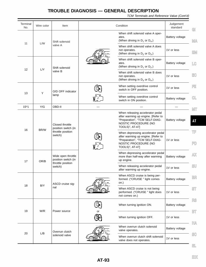
TerminalNo.
Wire color Item ConditionJudgementstandard
11 L/WShift solenoidvalve A
When shift solenoid valve A oper-ates.(When driving in D1 or D4.)
Battery voltage
When shift solenoid valve A doesnot operates.(When driving in D2 or D3.)
1V or less
12 L/YShift solenoidvalve B
When shift solenoid valve B oper-ates.(When driving in D1 or D2.)
Battery voltage
When shift solenoid valve B doesnot operates.(When driving in D3 or D4.)
1V or less
13 YO/D OFF indicatorlamp
When setting overdrive controlswitch in OFF position.
1V or less
When setting overdrive controlswitch in ON position.
Battery voltage
15*1 Y/G OBD-II — — —
16 BR/W
Closed throttleposition switch (inthrottle positionswitch)
When releasing accelerator pedalafter warming up engine. [Refer to“Preparation”, “TCM SELF-DIAG-NOSTIC PROCEDURE (NOTOOLS)”, AT-47]
Battery voltage
When depressing accelerator pedalafter warming up engine. [Refer to“Preparation”, “TCM SELF-DIAG-NOSTIC PROCEDURE (NOTOOLS)”, AT-47]
1V or less
17 OR/B
Wide open throttleposition switch (inthrottle positionswitch)
When depressing accelerator pedalmore than half-way after warmingup engine.
Battery voltage
When releasing accelerator pedalafter warming up engine.
1V or less
18 B/YASCD cruise sig-nal
When ASCD cruise is being per-formed. (“CRUISE ” light comeson.)
Battery voltage
When ASCD cruise is not beingperformed. (“CRUISE ” light doesnot comes on.)
1V or less
19 W/R Power source or
When turning ignition ON. Battery voltage
When turning ignition OFF. 1V or less
20 L/BOverrun clutchsolenoid valve
When overrun clutch solenoidvalve operates.
Battery voltage
When overrun clutch shift solenoidvalve does not operates.
1V or less
GI
MA
EM
LC
EC
FE
CL
MT
TF
PD
AX
SU
BR
ST
RS
BT
HA
SC
EL
IDX
TROUBLE DIAGNOSIS — GENERAL DESCRIPTIONTCM Terminals and Reference Value (Cont’d)
AT-93
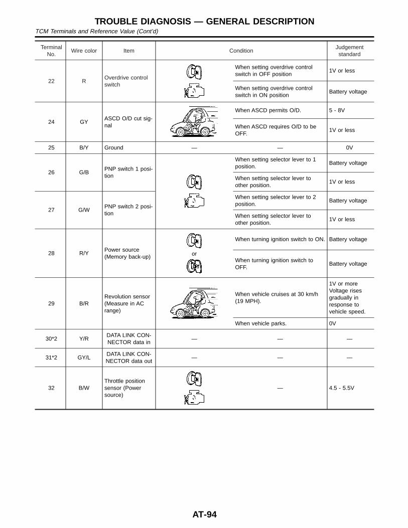
TerminalNo.
Wire color Item ConditionJudgementstandard
22 ROverdrive controlswitch
When setting overdrive controlswitch in OFF position
1V or less
When setting overdrive controlswitch in ON position
Battery voltage
24 GYASCD O/D cut sig-nal
When ASCD permits O/D. 5 - 8V
When ASCD requires O/D to beOFF.
1V or less
25 B/Y Ground — — 0V
26 G/BPNP switch 1 posi-tion
When setting selector lever to 1position.
Battery voltage
When setting selector lever toother position.
1V or less
27 G/WPNP switch 2 posi-tion
When setting selector lever to 2position.
Battery voltage
When setting selector lever toother position.
1V or less
28 R/YPower source(Memory back-up) or
When turning ignition switch to ON. Battery voltage
When turning ignition switch toOFF.
Battery voltage
29 B/RRevolution sensor(Measure in ACrange)
When vehicle cruises at 30 km/h(19 MPH).
1V or moreVoltage risesgradually inresponse tovehicle speed.
When vehicle parks. 0V
30*2 Y/RDATA LINK CON-NECTOR data in
— — —
31*2 GY/LDATA LINK CON-NECTOR data out
— — —
32 B/WThrottle positionsensor (Powersource)
— 4.5 - 5.5V
TROUBLE DIAGNOSIS — GENERAL DESCRIPTIONTCM Terminals and Reference Value (Cont’d)
AT-94
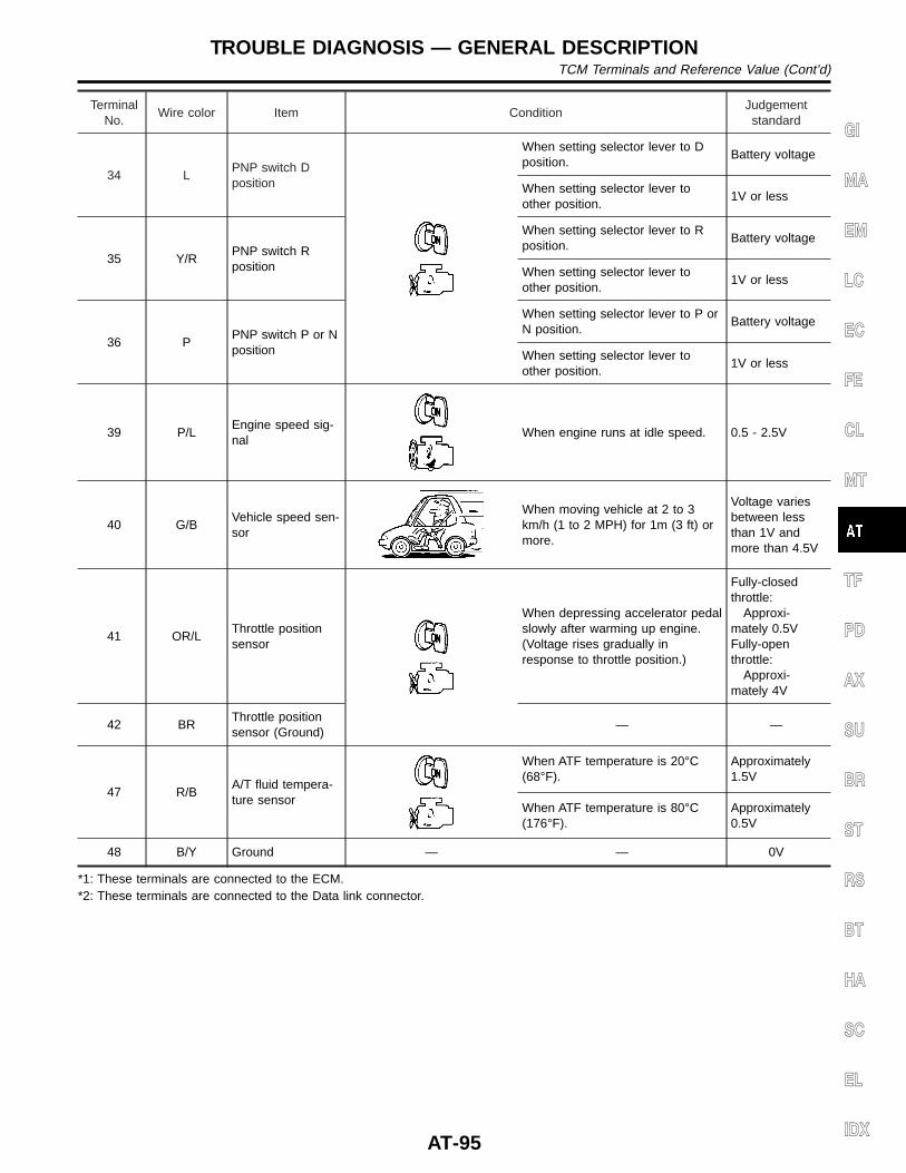
TerminalNo.
Wire color Item ConditionJudgementstandard
34 LPNP switch Dposition
When setting selector lever to Dposition.
Battery voltage
When setting selector lever toother position.
1V or less
35 Y/RPNP switch Rposition
When setting selector lever to Rposition.
Battery voltage
When setting selector lever toother position.
1V or less
36 PPNP switch P or Nposition
When setting selector lever to P orN position.
Battery voltage
When setting selector lever toother position.
1V or less
39 P/LEngine speed sig-nal
When engine runs at idle speed. 0.5 - 2.5V
40 G/BVehicle speed sen-sor
When moving vehicle at 2 to 3km/h (1 to 2 MPH) for 1m (3 ft) ormore.
Voltage variesbetween lessthan 1V andmore than 4.5V
41 OR/LThrottle positionsensor
When depressing accelerator pedalslowly after warming up engine.(Voltage rises gradually inresponse to throttle position.)
Fully-closedthrottle:
Approxi-mately 0.5VFully-openthrottle:
Approxi-mately 4V
42 BRThrottle positionsensor (Ground)
— —
47 R/BA/T fluid tempera-ture sensor
When ATF temperature is 20°C(68°F).
Approximately1.5V
When ATF temperature is 80°C(176°F).
Approximately0.5V
48 B/Y Ground — — 0V
*1: These terminals are connected to the ECM.*2: These terminals are connected to the Data link connector.
GI
MA
EM
LC
EC
FE
CL
MT
TF
PD
AX
SU
BR
ST
RS
BT
HA
SC
EL
IDX
TROUBLE DIAGNOSIS — GENERAL DESCRIPTIONTCM Terminals and Reference Value (Cont’d)
AT-95
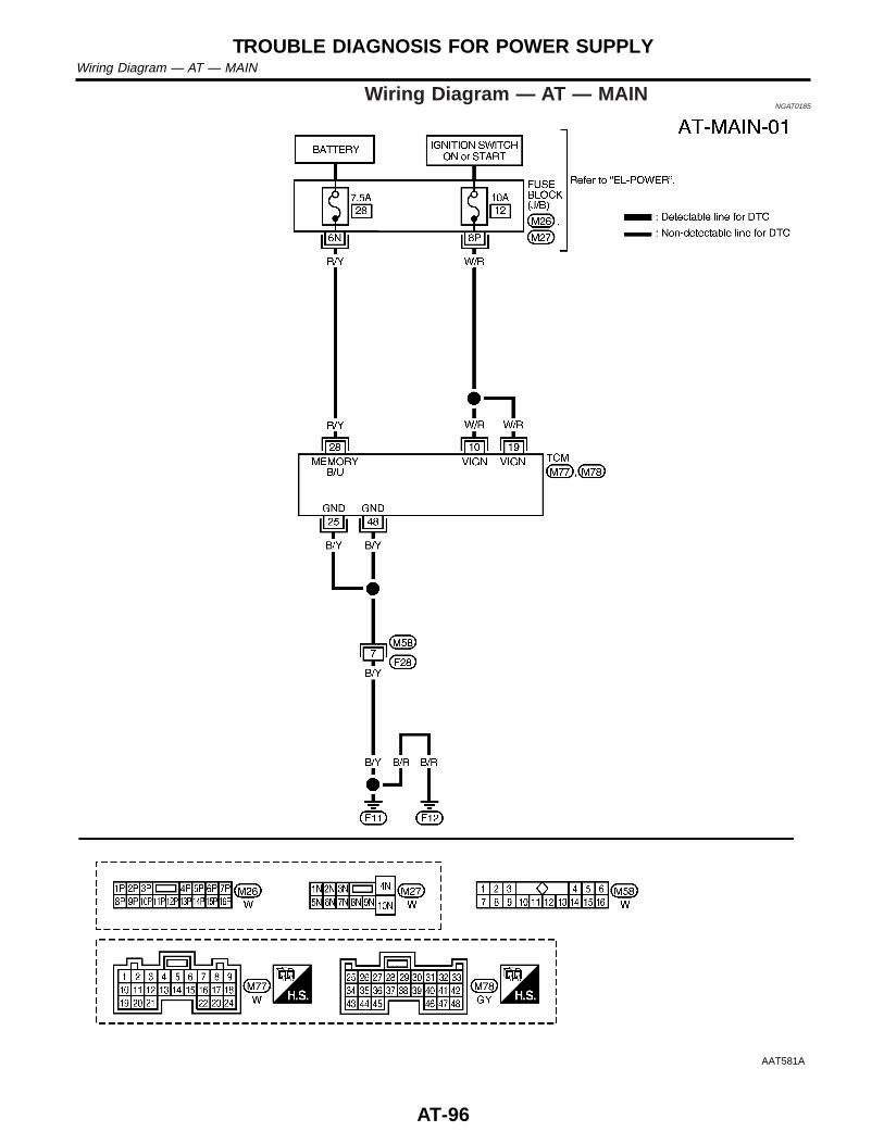
Wiring Diagram — AT — MAINNGAT0185
AAT581A
TROUBLE DIAGNOSIS FOR POWER SUPPLYWiring Diagram — AT — MAIN
AT-96
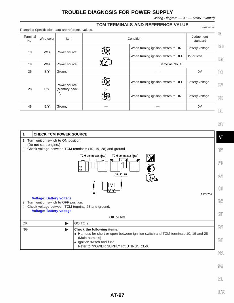
TCM TERMINALS AND REFERENCE VALUENGAT0185S01
Remarks: Specification data are reference values.
TerminalNo.
Wire color Item ConditionJudgementstandard
10 W/R Power sourceWhen turning ignition switch to ON Battery voltage
When turning ignition switch to OFF 1V or less
19 W/R Power source Same as No. 10
25 B/Y Ground — — 0V
28 R/YPower source(Memory back-up)
or
When turning ignition switch to OFF Battery voltage
When turning ignition switch to ON Battery voltage
48 B/Y Ground — — 0V
1 CHECK TCM POWER SOURCE
1. Turn ignition switch to ON position.(Do not start engine.)
2. Check voltage between TCM terminals (10, 19, 28) and ground.
AAT476A
Voltage: Battery voltage3. Turn ignition switch to OFF position.4. Check voltage between TCM terminal 28 and ground.
Voltage: Battery voltage
OK or NG
OK © GO TO 2.
NG © Check the following items:I Harness for short or open between ignition switch and TCM terminals 10, 19 and 28
(Main harness)I Ignition switch and fuse
Refer to “POWER SUPPLY ROUTING”, EL-9.
GI
MA
EM
LC
EC
FE
CL
MT
TF
PD
AX
SU
BR
ST
RS
BT
HA
SC
EL
IDX
TROUBLE DIAGNOSIS FOR POWER SUPPLYWiring Diagram — AT — MAIN (Cont’d)
AT-97
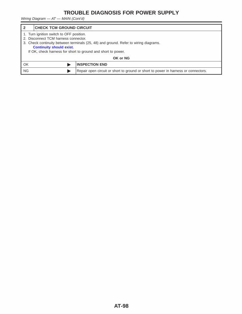
2 CHECK TCM GROUND CIRCUIT
1. Turn ignition switch to OFF position.2. Disconnect TCM harness connector.3. Check continuity between terminals (25, 48) and ground. Refer to wiring diagrams.
Continuity should exist.If OK, check harness for short to ground and short to power.
OK or NG
OK © INSPECTION END
NG © Repair open circuit or short to ground or short to power in harness or connectors.
TROUBLE DIAGNOSIS FOR POWER SUPPLYWiring Diagram — AT — MAIN (Cont’d)
AT-98
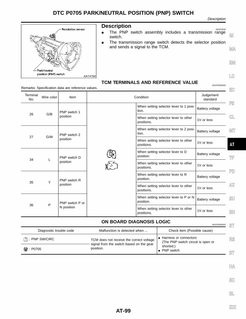
AAT478A
DescriptionNGAT0028
I The PNP switch assembly includes a transmission rangeswitch.
I The transmission range switch detects the selector positionand sends a signal to the TCM.
TCM TERMINALS AND REFERENCE VALUENGAT0028S02
Remarks: Specification data are reference values.
TerminalNo.
Wire color Item ConditionJudgementstandard
26 G/BPNP switch 1position
When setting selector lever to 1 posi-tion.
Battery voltage
When setting selector lever to otherpositions.
1V or less
27 G/WPNP switch 2position
When setting selector lever to 2 posi-tion.
Battery voltage
When setting selector lever to otherpositions.
1V or less
34 LPNP switch Dposition
When setting selector lever to Dposition.
Battery voltage
When setting selector lever to otherpositions.
1V or less
35 YPNP switch Rposition
When setting selector lever to Rposition.
Battery voltage
When setting selector lever to otherpositions.
1V or less
36 PPNP switch P orN position
When setting selector lever to P or Nposition.
Battery voltage
When setting selector lever to otherpositions.
1V or less
ON BOARD DIAGNOSIS LOGICNGAT0028S03
Diagnostic trouble code Malfunction is detected when ... Check item (Possible cause)
: PNP SW/CIRC TCM does not receive the correct voltagesignal from the switch based on the gearposition.
I Harness or connectors(The PNP switch circuit is open orshorted.)
I PNP switch: P0705
GI
MA
EM
LC
EC
FE
CL
MT
TF
PD
AX
SU
BR
ST
RS
BT
HA
SC
EL
IDX
DTC P0705 PARK/NEUTRAL POSITION (PNP) SWITCHDescription
AT-99
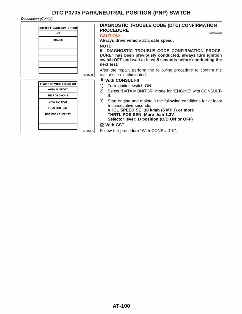
SAT580J
SAT617J
DIAGNOSTIC TROUBLE CODE (DTC) CONFIRMATIONPROCEDURE
NGAT0028S01
CAUTION:Always drive vehicle at a safe speed.NOTE:If “DIAGNOSTIC TROUBLE CODE CONFIRMATION PROCE-DURE” has been previously conducted, always turn ignitionswitch OFF and wait at least 5 seconds before conducting thenext test.After the repair, perform the following procedure to confirm themalfunction is eliminated.
With CONSULT-II1) Turn ignition switch ON.2) Select “DATA MONITOR” mode for “ENGINE” with CONSULT-
II.3) Start engine and maintain the following conditions for at least
5 consecutive seconds.VHCL SPEED SE: 10 km/h (6 MPH) or moreTHRTL POS SEN: More than 1.3VSelector lever: D position (O/D ON or OFF)
With GSTFollow the procedure “With CONSULT-II”.
DTC P0705 PARK/NEUTRAL POSITION (PNP) SWITCHDescription (Cont’d)
AT-100
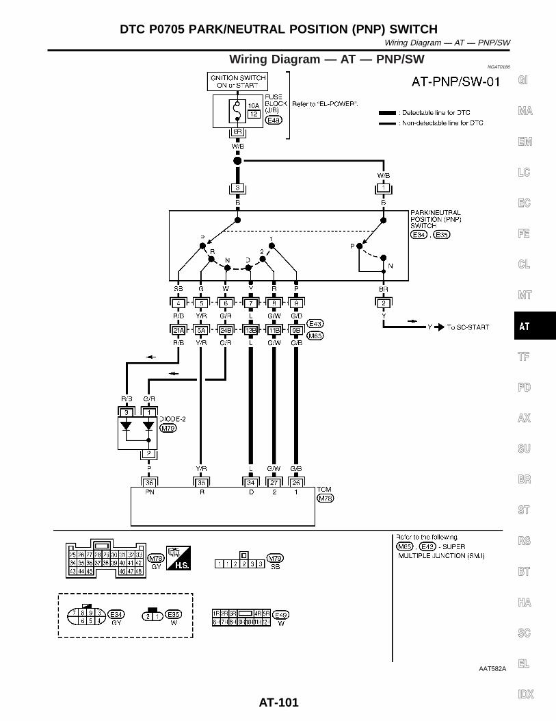
Wiring Diagram — AT — PNP/SWNGAT0186
AAT582A
GI
MA
EM
LC
EC
FE
CL
MT
TF
PD
AX
SU
BR
ST
RS
BT
HA
SC
EL
IDX
DTC P0705 PARK/NEUTRAL POSITION (PNP) SWITCHWiring Diagram — AT — PNP/SW
AT-101
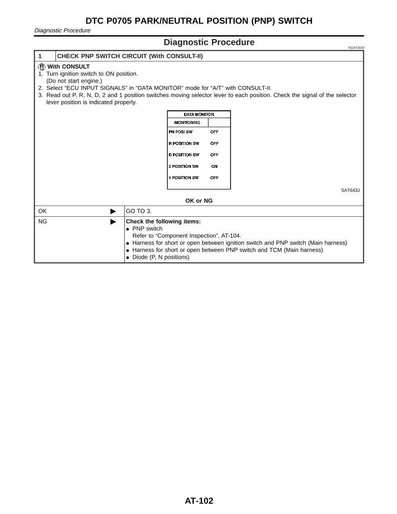
Diagnostic ProcedureNGAT0029
1 CHECK PNP SWITCH CIRCUIT (With CONSULT-II)
With CONSULT1. Turn ignition switch to ON position.
(Do not start engine.)2. Select “ECU INPUT SIGNALS” in “DATA MONITOR” mode for “A/T” with CONSULT-II.3. Read out P, R, N, D, 2 and 1 position switches moving selector lever to each position. Check the signal of the selector
lever position is indicated properly.
SAT643J
OK or NG
OK © GO TO 3.
NG © Check the following items:I PNP switch
Refer to “Component Inspection”, AT-104.I Harness for short or open between ignition switch and PNP switch (Main harness)I Harness for short or open between PNP switch and TCM (Main harness)I Diode (P, N positions)
DTC P0705 PARK/NEUTRAL POSITION (PNP) SWITCHDiagnostic Procedure
AT-102
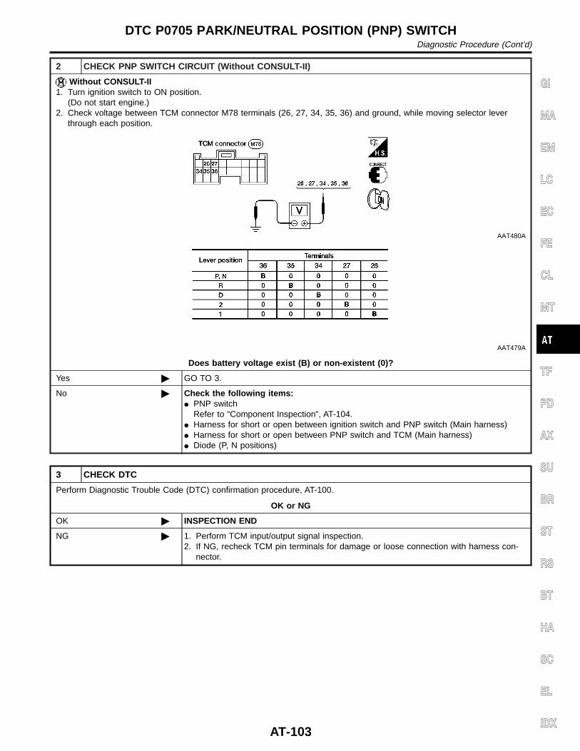
2 CHECK PNP SWITCH CIRCUIT (Without CONSULT-II)
Without CONSULT-II1. Turn ignition switch to ON position.
(Do not start engine.)2. Check voltage between TCM connector M78 terminals (26, 27, 34, 35, 36) and ground, while moving selector lever
through each position.
AAT480A
AAT479A
Does battery voltage exist (B) or non-existent (0)?
Yes © GO TO 3.
No © Check the following items:I PNP switch
Refer to “Component Inspection”, AT-104.I Harness for short or open between ignition switch and PNP switch (Main harness)I Harness for short or open between PNP switch and TCM (Main harness)I Diode (P, N positions)
3 CHECK DTC
Perform Diagnostic Trouble Code (DTC) confirmation procedure, AT-100.
OK or NG
OK © INSPECTION END
NG © 1. Perform TCM input/output signal inspection.2. If NG, recheck TCM pin terminals for damage or loose connection with harness con-
nector.
GI
MA
EM
LC
EC
FE
CL
MT
TF
PD
AX
SU
BR
ST
RS
BT
HA
SC
EL
IDX
DTC P0705 PARK/NEUTRAL POSITION (PNP) SWITCHDiagnostic Procedure (Cont’d)
AT-103
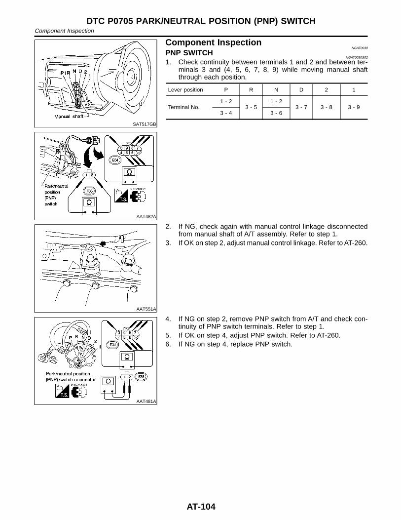
SAT517GB
AAT482A
Component InspectionNGAT0030
PNP SWITCHNGAT0030S02
1. Check continuity between terminals 1 and 2 and between ter-minals 3 and (4, 5, 6, 7, 8, 9) while moving manual shaftthrough each position.
Lever position P R N D 2 1
Terminal No.1 - 2
3 - 51 - 2
3 - 7 3 - 8 3 - 93 - 4 3 - 6
AAT551A
2. If NG, check again with manual control linkage disconnectedfrom manual shaft of A/T assembly. Refer to step 1.
3. If OK on step 2, adjust manual control linkage. Refer to AT-260.
AAT481A
4. If NG on step 2, remove PNP switch from A/T and check con-tinuity of PNP switch terminals. Refer to step 1.
5. If OK on step 4, adjust PNP switch. Refer to AT-260.6. If NG on step 4, replace PNP switch.
DTC P0705 PARK/NEUTRAL POSITION (PNP) SWITCHComponent Inspection
AT-104
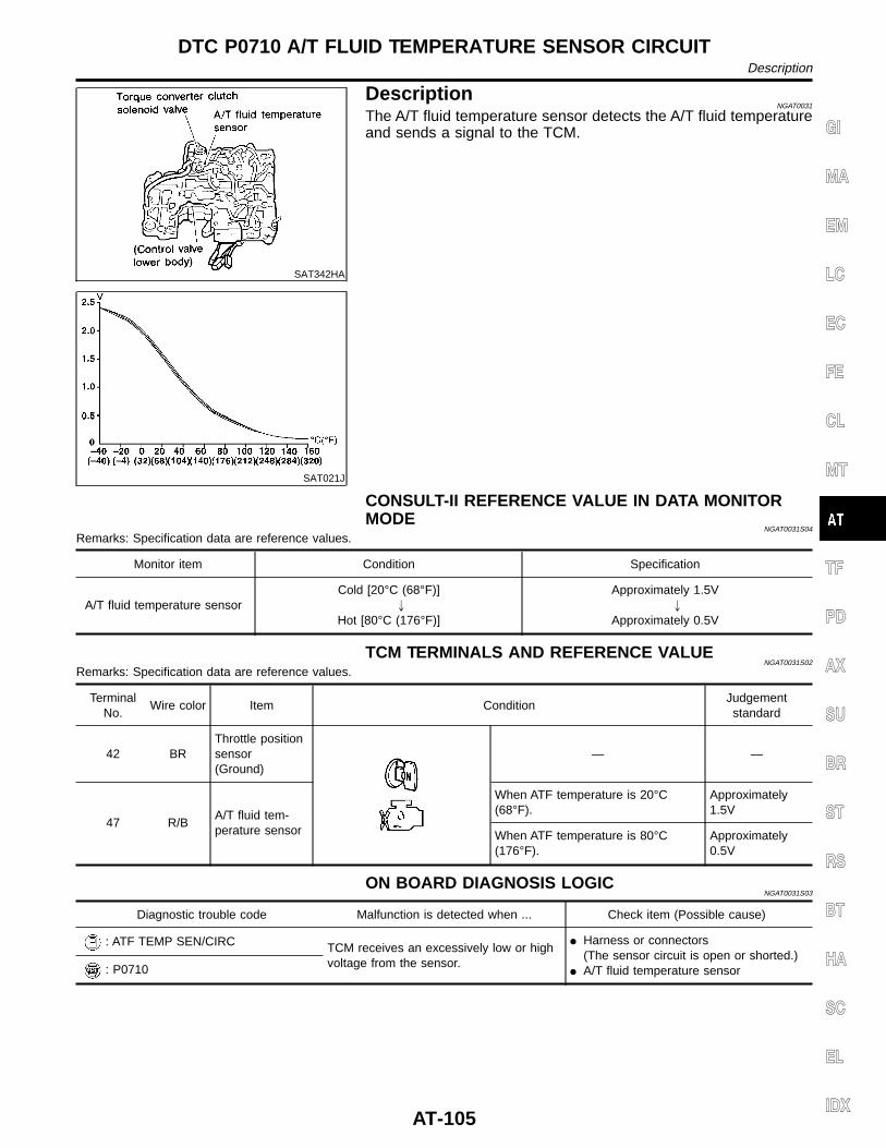
SAT342HA
DescriptionNGAT0031
The A/T fluid temperature sensor detects the A/T fluid temperatureand sends a signal to the TCM.
SAT021J
CONSULT-II REFERENCE VALUE IN DATA MONITORMODE
NGAT0031S04
Remarks: Specification data are reference values.
Monitor item Condition Specification
A/T fluid temperature sensorCold [20°C (68°F)]
"
Hot [80°C (176°F)]
Approximately 1.5V"
Approximately 0.5V
TCM TERMINALS AND REFERENCE VALUENGAT0031S02
Remarks: Specification data are reference values.
TerminalNo.
Wire color Item ConditionJudgementstandard
42 BRThrottle positionsensor(Ground)
— —
47 R/BA/T fluid tem-perature sensor
When ATF temperature is 20°C(68°F).
Approximately1.5V
When ATF temperature is 80°C(176°F).
Approximately0.5V
ON BOARD DIAGNOSIS LOGICNGAT0031S03
Diagnostic trouble code Malfunction is detected when ... Check item (Possible cause)
: ATF TEMP SEN/CIRC TCM receives an excessively low or highvoltage from the sensor.
I Harness or connectors(The sensor circuit is open or shorted.)
I A/T fluid temperature sensor: P0710
GI
MA
EM
LC
EC
FE
CL
MT
TF
PD
AX
SU
BR
ST
RS
BT
HA
SC
EL
IDX
DTC P0710 A/T FLUID TEMPERATURE SENSOR CIRCUITDescription
AT-105
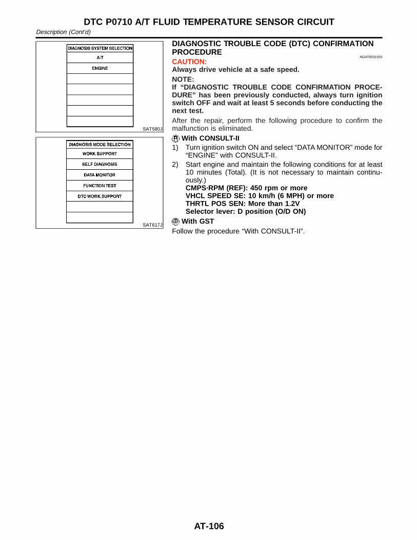
SAT580J
SAT617J
DIAGNOSTIC TROUBLE CODE (DTC) CONFIRMATIONPROCEDURE
NGAT0031S01
CAUTION:Always drive vehicle at a safe speed.NOTE:If “DIAGNOSTIC TROUBLE CODE CONFIRMATION PROCE-DURE” has been previously conducted, always turn ignitionswitch OFF and wait at least 5 seconds before conducting thenext test.After the repair, perform the following procedure to confirm themalfunction is eliminated.
With CONSULT-II1) Turn ignition switch ON and select “DATA MONITOR” mode for
“ENGINE” with CONSULT-II.2) Start engine and maintain the following conditions for at least
10 minutes (Total). (It is not necessary to maintain continu-ously.)CMPS·RPM (REF): 450 rpm or moreVHCL SPEED SE: 10 km/h (6 MPH) or moreTHRTL POS SEN: More than 1.2VSelector lever: D position (O/D ON)
With GSTFollow the procedure “With CONSULT-II”.
DTC P0710 A/T FLUID TEMPERATURE SENSOR CIRCUITDescription (Cont’d)
AT-106
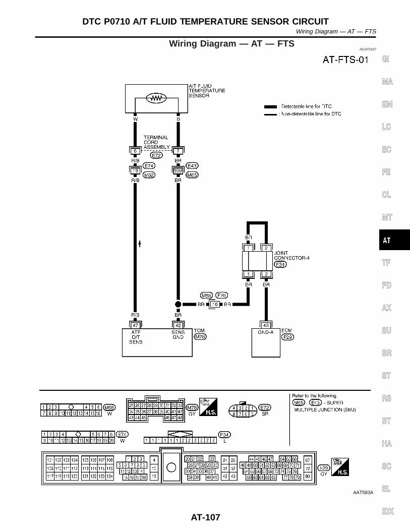
Wiring Diagram — AT — FTSNGAT0187
AAT583A
GI
MA
EM
LC
EC
FE
CL
MT
TF
PD
AX
SU
BR
ST
RS
BT
HA
SC
EL
IDX
DTC P0710 A/T FLUID TEMPERATURE SENSOR CIRCUITWiring Diagram — AT — FTS
AT-107
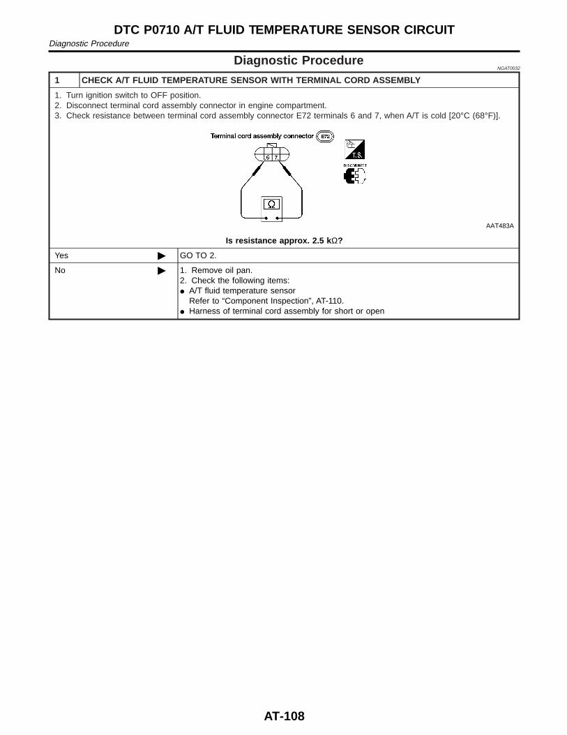
Diagnostic ProcedureNGAT0032
1 CHECK A/T FLUID TEMPERATURE SENSOR WITH TERMINAL CORD ASSEMBLY
1. Turn ignition switch to OFF position.2. Disconnect terminal cord assembly connector in engine compartment.3. Check resistance between terminal cord assembly connector E72 terminals 6 and 7, when A/T is cold [20°C (68°F)].
AAT483A
Is resistance approx. 2.5 k Ω?
Yes © GO TO 2.
No © 1. Remove oil pan.2. Check the following items:I A/T fluid temperature sensor
Refer to “Component Inspection”, AT-110.I Harness of terminal cord assembly for short or open
DTC P0710 A/T FLUID TEMPERATURE SENSOR CIRCUITDiagnostic Procedure
AT-108
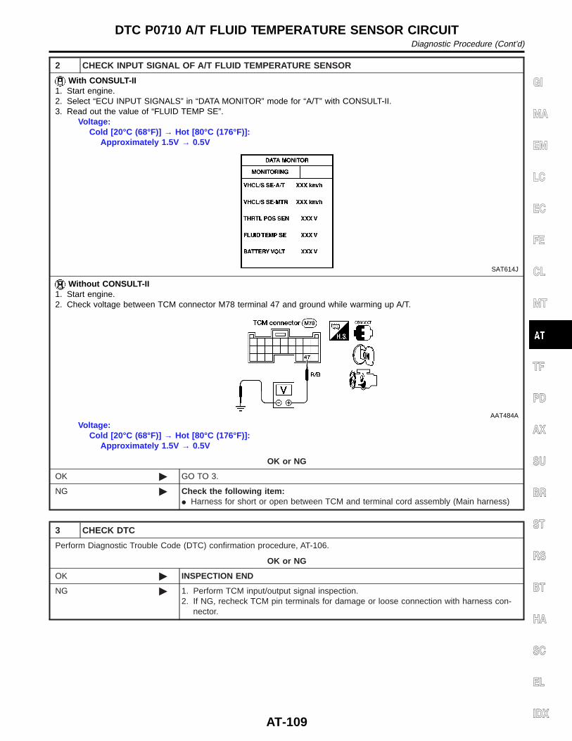
2 CHECK INPUT SIGNAL OF A/T FLUID TEMPERATURE SENSOR
With CONSULT-II1. Start engine.2. Select “ECU INPUT SIGNALS” in “DATA MONITOR” mode for “A/T” with CONSULT-II.3. Read out the value of “FLUID TEMP SE”.
Voltage:Cold [20°C (68°F)] → Hot [80°C (176°F)]:
Approximately 1.5V → 0.5V
SAT614J
Without CONSULT-II1. Start engine.2. Check voltage between TCM connector M78 terminal 47 and ground while warming up A/T.
AAT484A
Voltage:Cold [20°C (68°F)] → Hot [80°C (176°F)]:
Approximately 1.5V → 0.5V
OK or NG
OK © GO TO 3.
NG © Check the following item:I Harness for short or open between TCM and terminal cord assembly (Main harness)
3 CHECK DTC
Perform Diagnostic Trouble Code (DTC) confirmation procedure, AT-106.
OK or NG
OK © INSPECTION END
NG © 1. Perform TCM input/output signal inspection.2. If NG, recheck TCM pin terminals for damage or loose connection with harness con-
nector.
GI
MA
EM
LC
EC
FE
CL
MT
TF
PD
AX
SU
BR
ST
RS
BT
HA
SC
EL
IDX
DTC P0710 A/T FLUID TEMPERATURE SENSOR CIRCUITDiagnostic Procedure (Cont’d)
AT-109
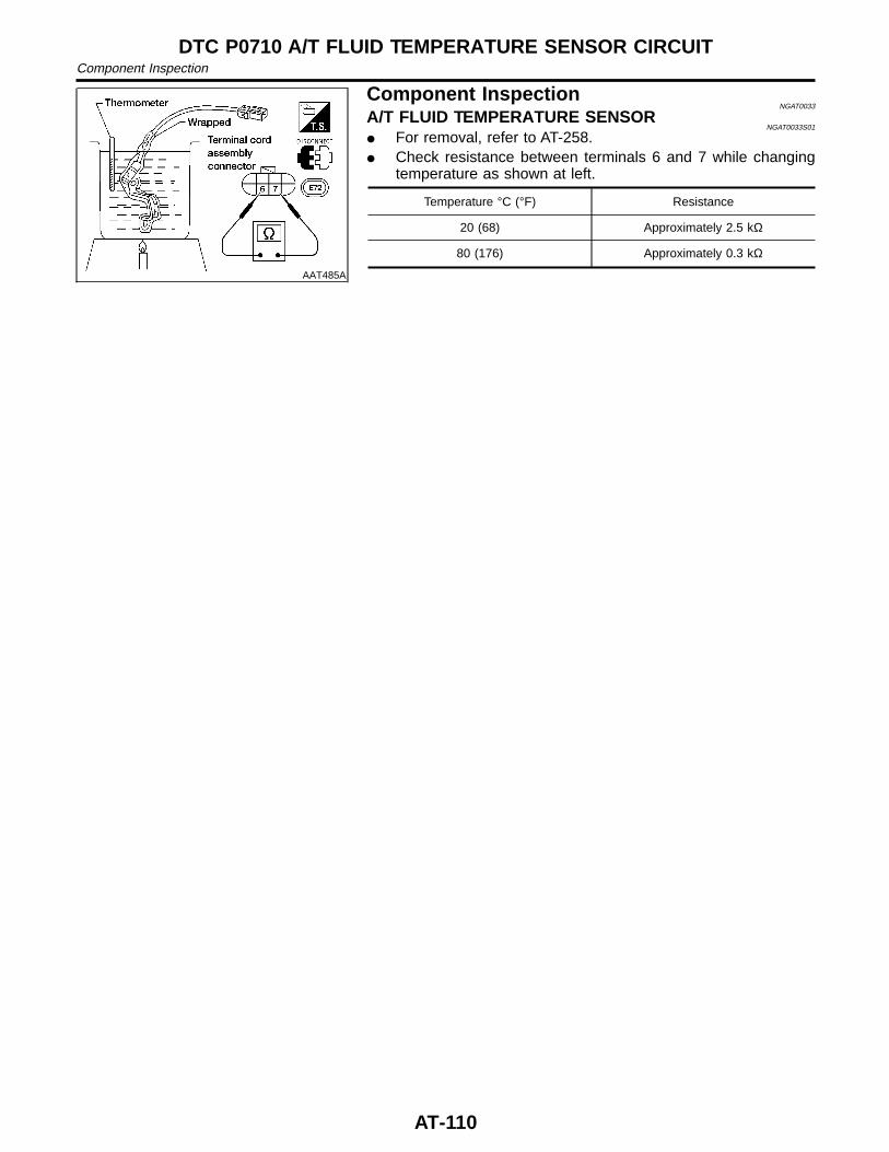
AAT485A
Component InspectionNGAT0033
A/T FLUID TEMPERATURE SENSORNGAT0033S01
I For removal, refer to AT-258.I Check resistance between terminals 6 and 7 while changing
temperature as shown at left.
Temperature °C (°F) Resistance
20 (68) Approximately 2.5 kΩ
80 (176) Approximately 0.3 kΩ
DTC P0710 A/T FLUID TEMPERATURE SENSOR CIRCUITComponent Inspection
AT-110
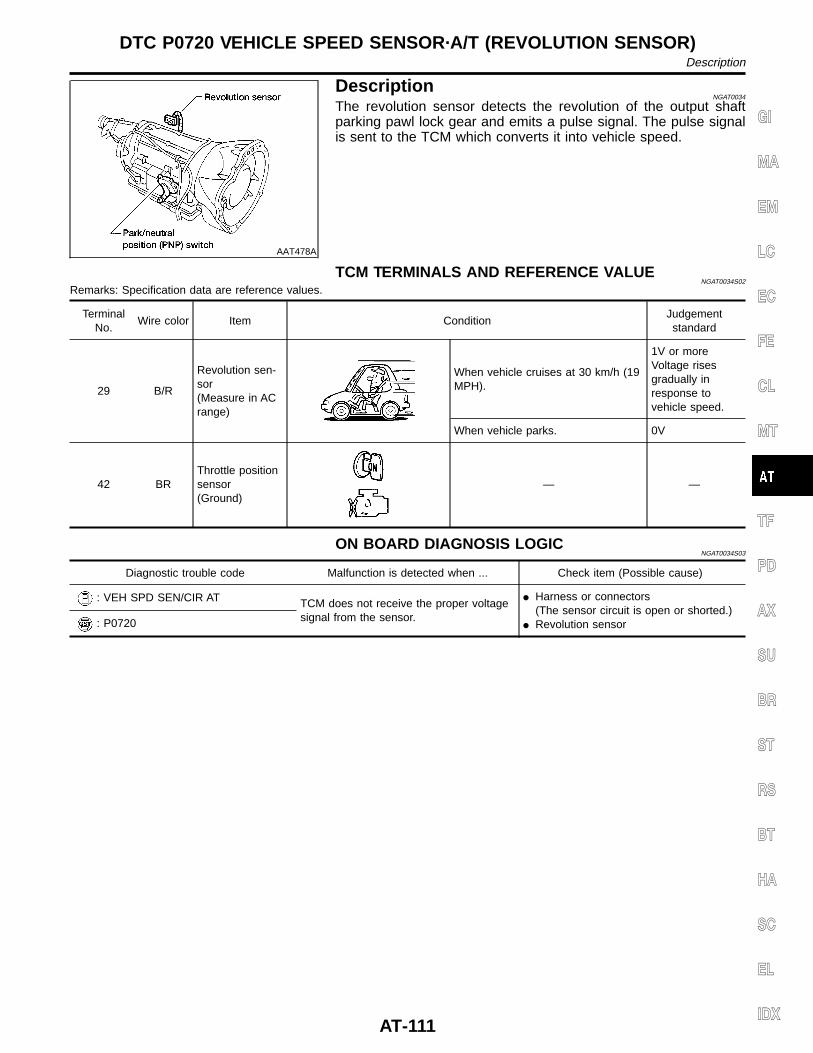
AAT478A
DescriptionNGAT0034
The revolution sensor detects the revolution of the output shaftparking pawl lock gear and emits a pulse signal. The pulse signalis sent to the TCM which converts it into vehicle speed.
TCM TERMINALS AND REFERENCE VALUENGAT0034S02
Remarks: Specification data are reference values.
TerminalNo.
Wire color Item ConditionJudgementstandard
29 B/R
Revolution sen-sor(Measure in ACrange)
When vehicle cruises at 30 km/h (19MPH).
1V or moreVoltage risesgradually inresponse tovehicle speed.
When vehicle parks. 0V
42 BRThrottle positionsensor(Ground)
— —
ON BOARD DIAGNOSIS LOGICNGAT0034S03
Diagnostic trouble code Malfunction is detected when ... Check item (Possible cause)
: VEH SPD SEN/CIR AT TCM does not receive the proper voltagesignal from the sensor.
I Harness or connectors(The sensor circuit is open or shorted.)
I Revolution sensor: P0720
GI
MA
EM
LC
EC
FE
CL
MT
TF
PD
AX
SU
BR
ST
RS
BT
HA
SC
EL
IDX
DTC P0720 VEHICLE SPEED SENSOR·A/T (REVOLUTION SENSOR)Description
AT-111
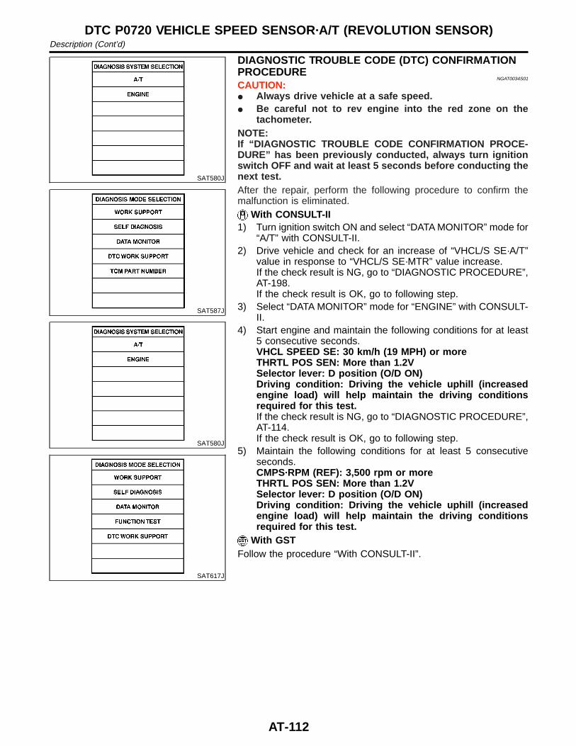
SAT580J
SAT587J
SAT580J
SAT617J
DIAGNOSTIC TROUBLE CODE (DTC) CONFIRMATIONPROCEDURE
NGAT0034S01
CAUTION:I Always drive vehicle at a safe speed.I Be careful not to rev engine into the red zone on the
tachometer.NOTE:If “DIAGNOSTIC TROUBLE CODE CONFIRMATION PROCE-DURE” has been previously conducted, always turn ignitionswitch OFF and wait at least 5 seconds before conducting thenext test.After the repair, perform the following procedure to confirm themalfunction is eliminated.
With CONSULT-II1) Turn ignition switch ON and select “DATA MONITOR” mode for
“A/T” with CONSULT-II.2) Drive vehicle and check for an increase of “VHCL/S SE·A/T”
value in response to “VHCL/S SE·MTR” value increase.If the check result is NG, go to “DIAGNOSTIC PROCEDURE”,AT-198.If the check result is OK, go to following step.
3) Select “DATA MONITOR” mode for “ENGINE” with CONSULT-II.
4) Start engine and maintain the following conditions for at least5 consecutive seconds.VHCL SPEED SE: 30 km/h (19 MPH) or moreTHRTL POS SEN: More than 1.2VSelector lever: D position (O/D ON)Driving condition: Driving the vehicle uphill (increasedengine load) will help maintain the driving conditionsrequired for this test.If the check result is NG, go to “DIAGNOSTIC PROCEDURE”,AT-114.If the check result is OK, go to following step.
5) Maintain the following conditions for at least 5 consecutiveseconds.CMPS·RPM (REF): 3,500 rpm or moreTHRTL POS SEN: More than 1.2VSelector lever: D position (O/D ON)Driving condition: Driving the vehicle uphill (increasedengine load) will help maintain the driving conditionsrequired for this test.
With GSTFollow the procedure “With CONSULT-II”.
DTC P0720 VEHICLE SPEED SENSOR·A/T (REVOLUTION SENSOR)Description (Cont’d)
AT-112
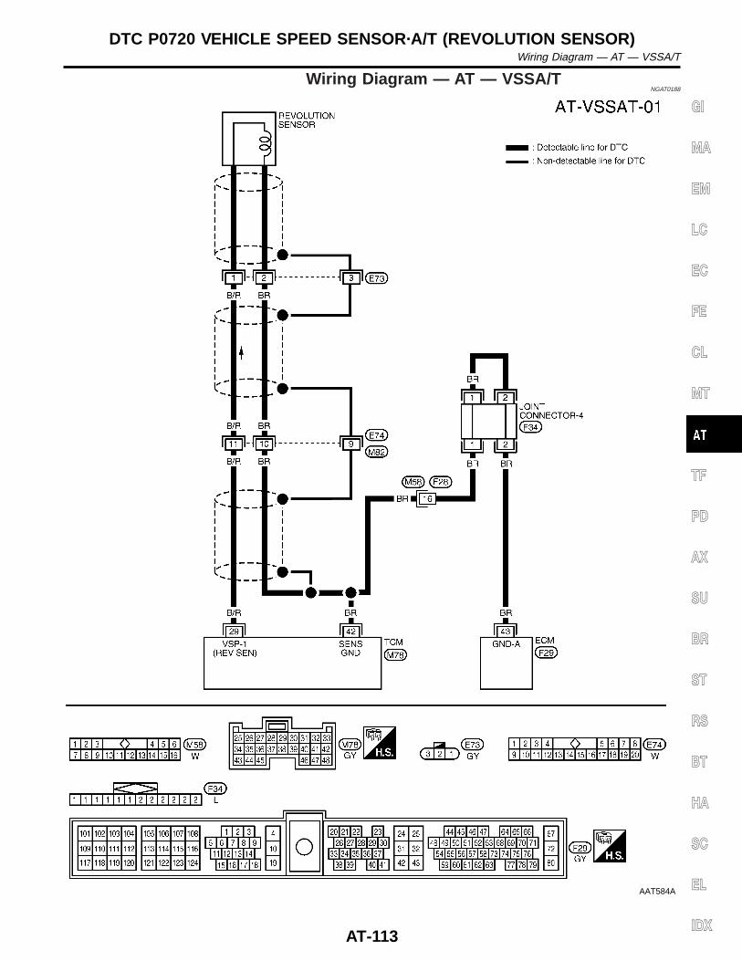
Wiring Diagram — AT — VSSA/TNGAT0188
AAT584A
GI
MA
EM
LC
EC
FE
CL
MT
TF
PD
AX
SU
BR
ST
RS
BT
HA
SC
EL
IDX
DTC P0720 VEHICLE SPEED SENSOR·A/T (REVOLUTION SENSOR)Wiring Diagram — AT — VSSA/T
AT-113
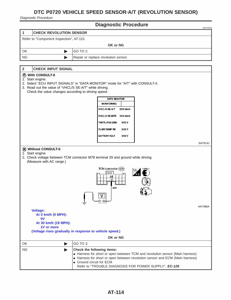
Diagnostic ProcedureNGAT0035
1 CHECK REVOLUTION SENSOR
Refer to “Component Inspection”, AT-115.
OK or NG
OK © GO TO 2.
NG © Repair or replace revolution sensor.
2 CHECK INPUT SIGNAL
With CONSULT-II1. Start engine.2. Select “ECU INPUT SIGNALS” in “DATA MONITOR” mode for “A/T” with CONSULT-II.3. Read out the value of “VHCL/S SE·A/T” while driving.
Check the value changes according to driving speed.
SAT614J
Without CONSULT-II1. Start engine.2. Check voltage between TCM connector M78 terminal 29 and ground while driving.
(Measure with AC range.)
AAT486A
Voltage:At 0 km/h (0 MPH):
0VAt 30 km/h (19 MPH):
1V or more(Voltage rises gradually in response to vehicle speed.)
OK or NG
OK © GO TO 3.
NG © Check the following items:I Harness for short or open between TCM and revolution sensor (Main harness)I Harness for short or open between revolution sensor and ECM (Main harness)I Ground circuit for ECM
Refer to “TROUBLE DIAGNOSIS FOR POWER SUPPLY”, EC-129.
DTC P0720 VEHICLE SPEED SENSOR·A/T (REVOLUTION SENSOR)Diagnostic Procedure
AT-114
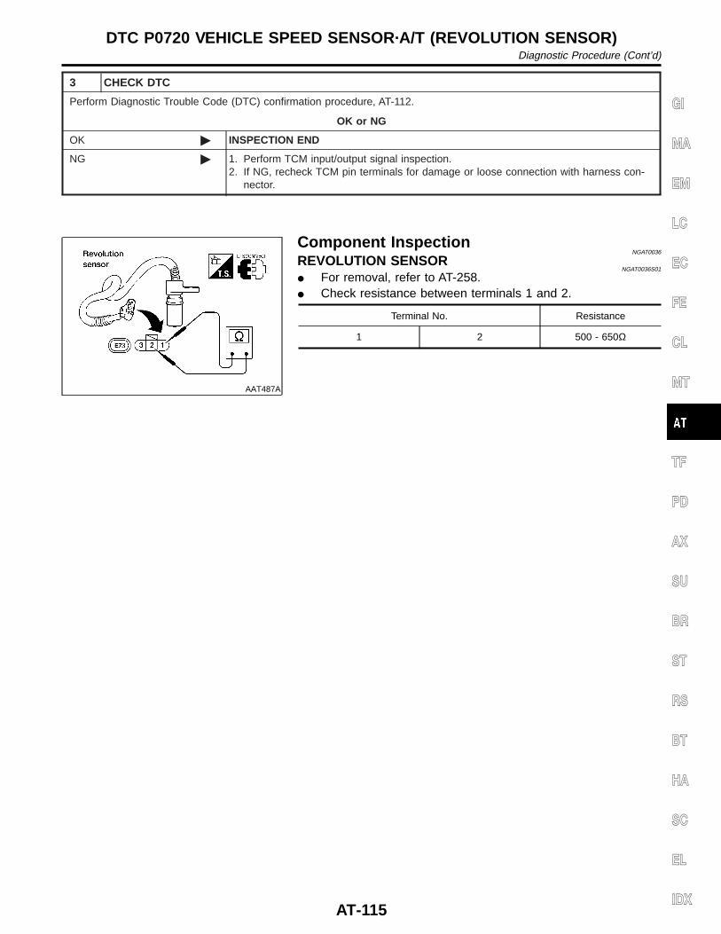
3 CHECK DTC
Perform Diagnostic Trouble Code (DTC) confirmation procedure, AT-112.
OK or NG
OK © INSPECTION END
NG © 1. Perform TCM input/output signal inspection.2. If NG, recheck TCM pin terminals for damage or loose connection with harness con-
nector.
AAT487A
Component InspectionNGAT0036
REVOLUTION SENSORNGAT0036S01
I For removal, refer to AT-258.I Check resistance between terminals 1 and 2.
Terminal No. Resistance
1 2 500 - 650Ω
GI
MA
EM
LC
EC
FE
CL
MT
TF
PD
AX
SU
BR
ST
RS
BT
HA
SC
EL
IDX
DTC P0720 VEHICLE SPEED SENSOR·A/T (REVOLUTION SENSOR)Diagnostic Procedure (Cont’d)
AT-115
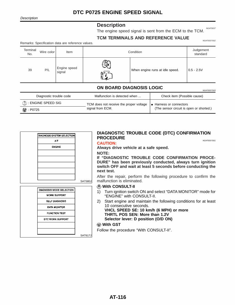
DescriptionNGAT0037
The engine speed signal is sent from the ECM to the TCM.
TCM TERMINALS AND REFERENCE VALUENGAT0037S02
Remarks: Specification data are reference values.
TerminalNo.
Wire color Item ConditionJudgementstandard
39 P/LEngine speedsignal
When engine runs at idle speed. 0.5 - 2.5V
ON BOARD DIAGNOSIS LOGICNGAT0037S03
Diagnostic trouble code Malfunction is detected when ... Check item (Possible cause)
: ENGINE SPEED SIG TCM does not receive the proper voltagesignal from ECM.
I Harness or connectors(The sensor circuit is open or shorted.): P0725
SAT580J
SAT617J
DIAGNOSTIC TROUBLE CODE (DTC) CONFIRMATIONPROCEDURE
NGAT0037S01
CAUTION:Always drive vehicle at a safe speed.NOTE:If “DIAGNOSTIC TROUBLE CODE CONFIRMATION PROCE-DURE” has been previously conducted, always turn ignitionswitch OFF and wait at least 5 seconds before conducting thenext test.After the repair, perform the following procedure to confirm themalfunction is eliminated.
With CONSULT-II1) Turn ignition switch ON and select “DATA MONITOR” mode for
“ENGINE” with CONSULT-II.2) Start engine and maintain the following conditions for at least
10 consecutive seconds.VHCL SPEED SE: 10 km/h (6 MPH) or moreTHRTL POS SEN: More than 1.2VSelector lever: D position (O/D ON)
With GSTFollow the procedure “With CONSULT-II”.
DTC P0725 ENGINE SPEED SIGNALDescription
AT-116
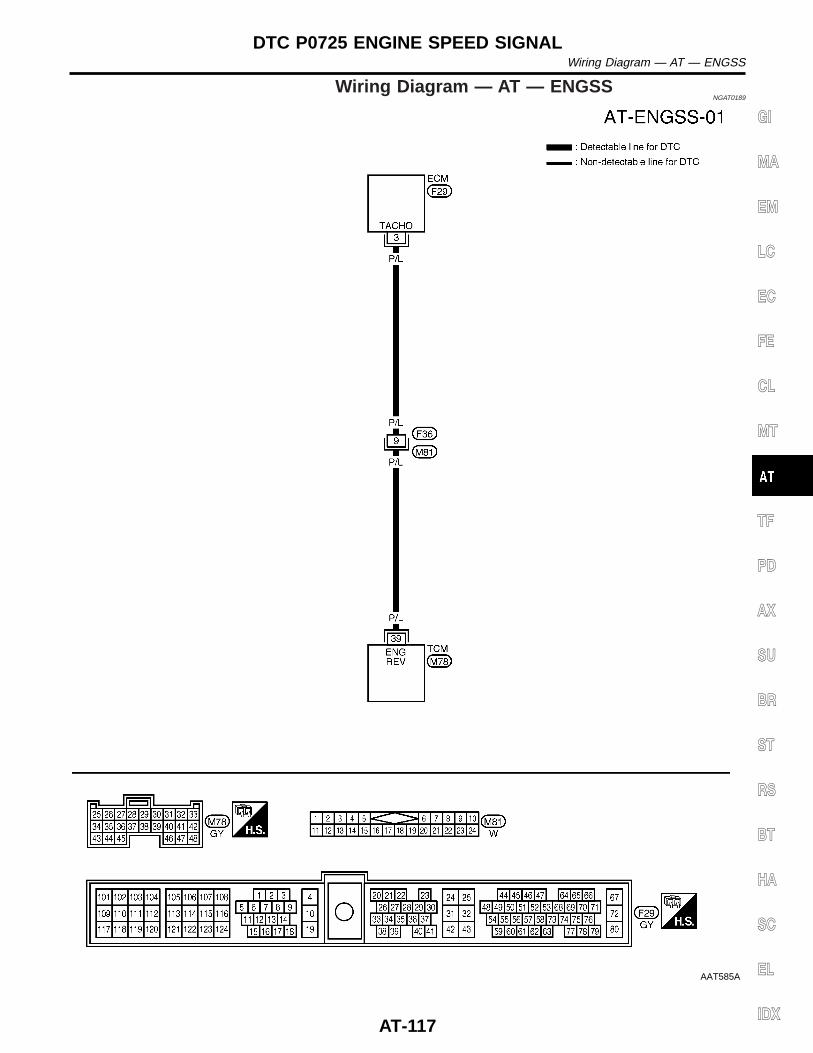
Wiring Diagram — AT — ENGSSNGAT0189
AAT585A
GI
MA
EM
LC
EC
FE
CL
MT
TF
PD
AX
SU
BR
ST
RS
BT
HA
SC
EL
IDX
DTC P0725 ENGINE SPEED SIGNALWiring Diagram — AT — ENGSS
AT-117
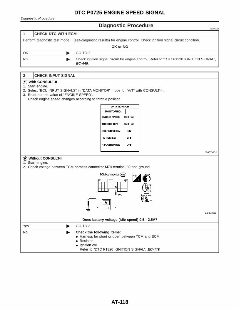
Diagnostic ProcedureNGAT0038
1 CHECK DTC WITH ECM
Perform diagnostic test mode II (self-diagnostic results) for engine control. Check ignition signal circuit condition.
OK or NG
OK © GO TO 2.
NG © Check ignition signal circuit for engine control. Refer to “DTC P1320 IGNITION SIGNAL”,EC-449.
2 CHECK INPUT SIGNAL
With CONSULT-II1. Start engine.2. Select “ECU INPUT SIGNALS” in “DATA MONITOR” mode for “A/T” with CONSULT-II.3. Read out the value of “ENGINE SPEED”.
Check engine speed changes according to throttle position.
SAT645J
Without CONSULT-II1. Start engine.2. Check voltage between TCM harness connector M78 terminal 39 and ground.
AAT488A
Does battery voltage (idle speed) 0.5 - 2.5V?
Yes © GO TO 3.
No © Check the following items:I Harness for short or open between TCM and ECMI ResistorI Ignition coil
Refer to “DTC P1320 IGNITION SIGNAL”, EC-449.
DTC P0725 ENGINE SPEED SIGNALDiagnostic Procedure
AT-118
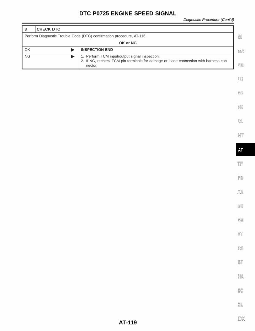
3 CHECK DTC
Perform Diagnostic Trouble Code (DTC) confirmation procedure, AT-116.
OK or NG
OK © INSPECTION END
NG © 1. Perform TCM input/output signal inspection.2. If NG, recheck TCM pin terminals for damage or loose connection with harness con-
nector.
GI
MA
EM
LC
EC
FE
CL
MT
TF
PD
AX
SU
BR
ST
RS
BT
HA
SC
EL
IDX
DTC P0725 ENGINE SPEED SIGNALDiagnostic Procedure (Cont’d)
AT-119
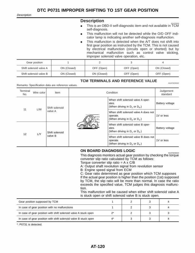
DescriptionNGAT0039
I This is an OBD-II self-diagnostic item and not available in TCMself-diagnosis.
I This malfunction will not be detected while the O/D OFF indi-cator lamp is indicating another self-diagnosis malfunction.
I This malfunction is detected when the A/T does not shift intofirst gear position as instructed by the TCM. This is not causedby electrical malfunction (circuits open or shorted) but bymechanical malfunction such as control valve sticking,improper solenoid valve operation, etc.
Gear position 1 2 3 4
Shift solenoid valve A ON (Closed) OFF (Open) OFF (Open) ON (Closed)
Shift solenoid valve B ON (Closed) ON (Closed) OFF (Open) OFF (Open)
TCM TERMINALS AND REFERENCE VALUENGAT0039S02
Remarks: Specification data are reference values.
TerminalNo.
Wire color Item ConditionJudgementstandard
11 L/WShift solenoidvalve A
When shift solenoid valve A oper-ates.(When driving in D1 or D4.)
Battery voltage
When shift solenoid valve A does notoperate.(When driving in D2 or D3.)
1V or less
12 L/YShift solenoidvalve B
When shift solenoid valve B oper-ates.(When driving in D1 or D2.)
Battery voltage
When shift solenoid valve B does notoperate.(When driving in D3 or D4.)
1V or less
ON BOARD DIAGNOSIS LOGICNGAT0039S03
This diagnosis monitors actual gear position by checking the torqueconverter slip ratio calculated by TCM as follows:Torque converter slip ratio = A x C/BA: Output shaft revolution signal from revolution sensorB: Engine speed signal from ECMC: Gear ratio determined as gear position which TCM supposesIf the actual gear position is higher than the position (1st) supposedby TCM, the slip ratio will be more than normal. In case the ratioexceeds the specified value, TCM judges this diagnosis malfunc-tion.This malfunction will be caused when either shift solenoid valve Ais stuck open or shift solenoid valve B is stuck open.
Gear position supposed by TCM 1 2 3 4
In case of gear position with no malfunctions 1 2 3 4
In case of gear position with shift solenoid valve A stuck open 2* 2 3 3
In case of gear position with shift solenoid valve B stuck open 4* 3 3 4
*: P0731 is detected.
DTC P0731 IMPROPER SHIFTING TO 1ST GEAR POSITIONDescription
AT-120
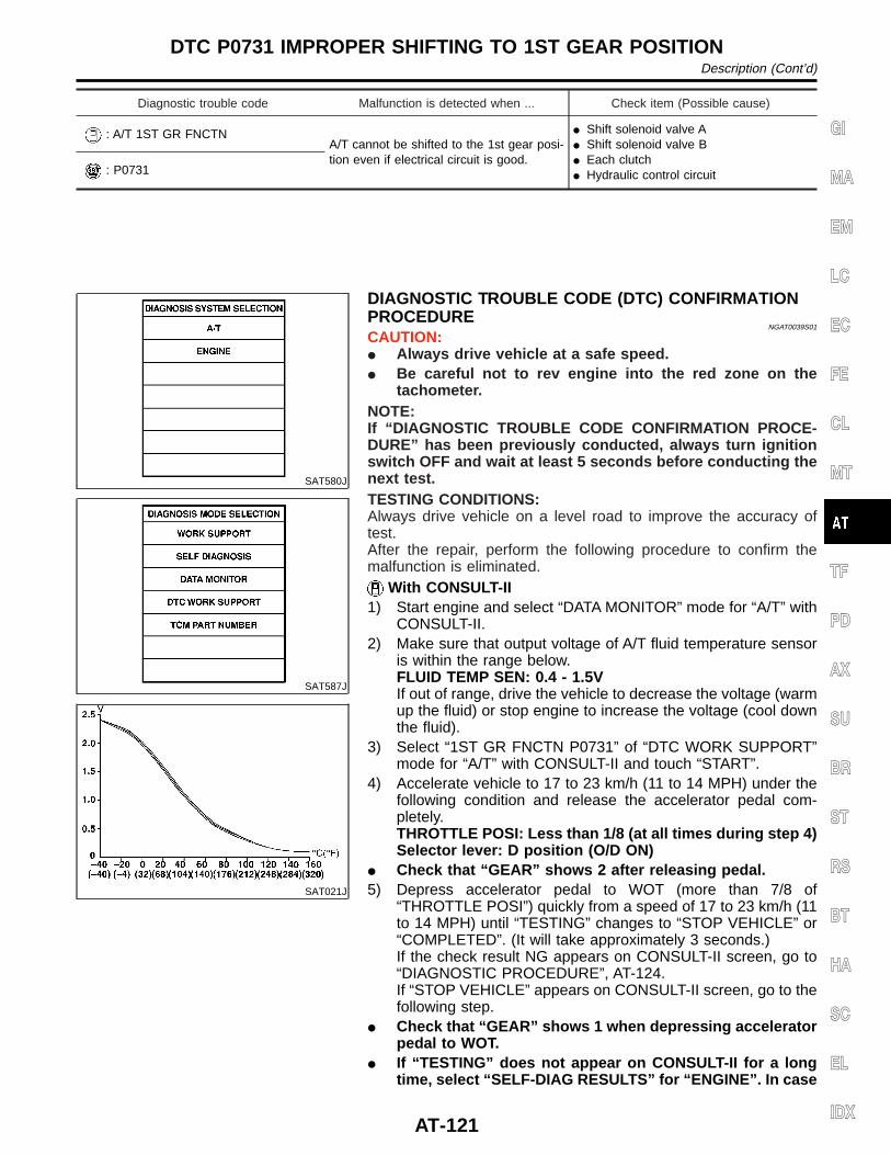
Diagnostic trouble code Malfunction is detected when ... Check item (Possible cause)
: A/T 1ST GR FNCTNA/T cannot be shifted to the 1st gear posi-tion even if electrical circuit is good.
I Shift solenoid valve AI Shift solenoid valve BI Each clutchI Hydraulic control circuit: P0731
SAT580J
SAT587J
SAT021J
DIAGNOSTIC TROUBLE CODE (DTC) CONFIRMATIONPROCEDURE
NGAT0039S01
CAUTION:I Always drive vehicle at a safe speed.I Be careful not to rev engine into the red zone on the
tachometer.NOTE:If “DIAGNOSTIC TROUBLE CODE CONFIRMATION PROCE-DURE” has been previously conducted, always turn ignitionswitch OFF and wait at least 5 seconds before conducting thenext test.TESTING CONDITIONS:Always drive vehicle on a level road to improve the accuracy oftest.After the repair, perform the following procedure to confirm themalfunction is eliminated.
With CONSULT-II1) Start engine and select “DATA MONITOR” mode for “A/T” with
CONSULT-II.2) Make sure that output voltage of A/T fluid temperature sensor
is within the range below.FLUID TEMP SEN: 0.4 - 1.5VIf out of range, drive the vehicle to decrease the voltage (warmup the fluid) or stop engine to increase the voltage (cool downthe fluid).
3) Select “1ST GR FNCTN P0731” of “DTC WORK SUPPORT”mode for “A/T” with CONSULT-II and touch “START”.
4) Accelerate vehicle to 17 to 23 km/h (11 to 14 MPH) under thefollowing condition and release the accelerator pedal com-pletely.THROTTLE POSI: Less than 1/8 (at all times during step 4)Selector lever: D position (O/D ON)
I Check that “GEAR” shows 2 after releasing pedal.5) Depress accelerator pedal to WOT (more than 7/8 of
“THROTTLE POSI”) quickly from a speed of 17 to 23 km/h (11to 14 MPH) until “TESTING” changes to “STOP VEHICLE” or“COMPLETED”. (It will take approximately 3 seconds.)If the check result NG appears on CONSULT-II screen, go to“DIAGNOSTIC PROCEDURE”, AT-124.If “STOP VEHICLE” appears on CONSULT-II screen, go to thefollowing step.
I Check that “GEAR” shows 1 when depressing acceleratorpedal to WOT.
I If “TESTING” does not appear on CONSULT-II for a longtime, select “SELF-DIAG RESULTS” for “ENGINE”. In case
GI
MA
EM
LC
EC
FE
CL
MT
TF
PD
AX
SU
BR
ST
RS
BT
HA
SC
EL
IDX
DTC P0731 IMPROPER SHIFTING TO 1ST GEAR POSITIONDescription (Cont’d)
AT-121
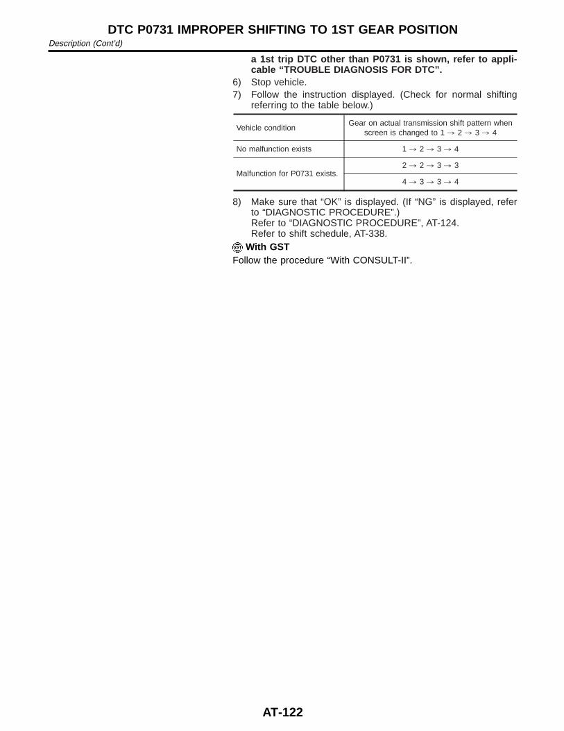
a 1st trip DTC other than P0731 is shown, refer to appli-cable “TROUBLE DIAGNOSIS FOR DTC”.
6) Stop vehicle.7) Follow the instruction displayed. (Check for normal shifting
referring to the table below.)
Vehicle conditionGear on actual transmission shift pattern when
screen is changed to 1 , 2 , 3 , 4
No malfunction exists 1 , 2 , 3 , 4
Malfunction for P0731 exists.2 , 2 , 3 , 3
4 , 3 , 3 , 4
8) Make sure that “OK” is displayed. (If “NG” is displayed, referto “DIAGNOSTIC PROCEDURE”.)Refer to “DIAGNOSTIC PROCEDURE”, AT-124.Refer to shift schedule, AT-338.
With GSTFollow the procedure “With CONSULT-II”.
DTC P0731 IMPROPER SHIFTING TO 1ST GEAR POSITIONDescription (Cont’d)
AT-122
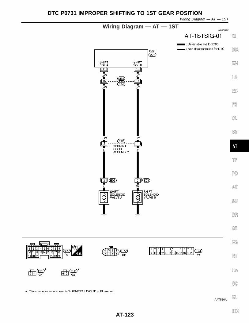
Wiring Diagram — AT — 1STNGAT0190
AAT586A
GI
MA
EM
LC
EC
FE
CL
MT
TF
PD
AX
SU
BR
ST
RS
BT
HA
SC
EL
IDX
DTC P0731 IMPROPER SHIFTING TO 1ST GEAR POSITIONWiring Diagram — AT — 1ST
AT-123
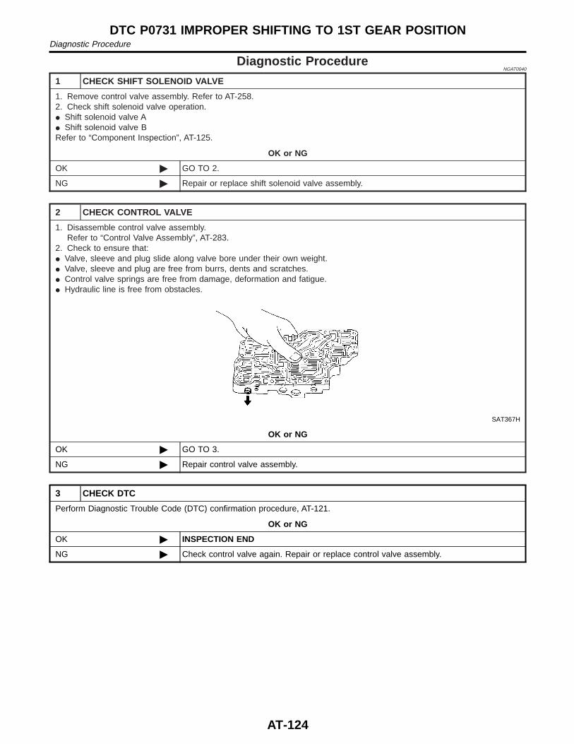
Diagnostic ProcedureNGAT0040
1 CHECK SHIFT SOLENOID VALVE
1. Remove control valve assembly. Refer to AT-258.2. Check shift solenoid valve operation.I Shift solenoid valve AI Shift solenoid valve BRefer to “Component Inspection”, AT-125.
OK or NG
OK © GO TO 2.
NG © Repair or replace shift solenoid valve assembly.
2 CHECK CONTROL VALVE
1. Disassemble control valve assembly.Refer to “Control Valve Assembly”, AT-283.
2. Check to ensure that:I Valve, sleeve and plug slide along valve bore under their own weight.I Valve, sleeve and plug are free from burrs, dents and scratches.I Control valve springs are free from damage, deformation and fatigue.I Hydraulic line is free from obstacles.
SAT367H
OK or NG
OK © GO TO 3.
NG © Repair control valve assembly.
3 CHECK DTC
Perform Diagnostic Trouble Code (DTC) confirmation procedure, AT-121.
OK or NG
OK © INSPECTION END
NG © Check control valve again. Repair or replace control valve assembly.
DTC P0731 IMPROPER SHIFTING TO 1ST GEAR POSITIONDiagnostic Procedure
AT-124
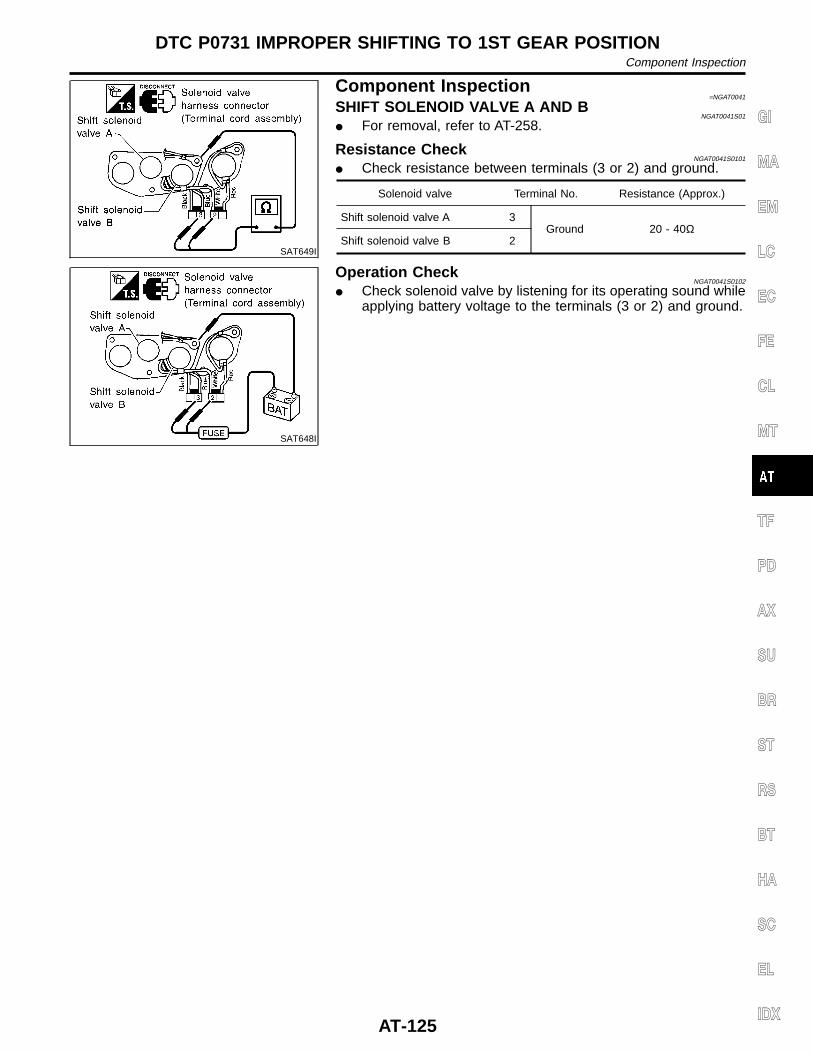
SAT649I
Component Inspection=NGAT0041
SHIFT SOLENOID VALVE A AND BNGAT0041S01
I For removal, refer to AT-258.
Resistance CheckNGAT0041S0101
I Check resistance between terminals (3 or 2) and ground.
Solenoid valve Terminal No. Resistance (Approx.)
Shift solenoid valve A 3Ground 20 - 40Ω
Shift solenoid valve B 2
SAT648I
Operation CheckNGAT0041S0102
I Check solenoid valve by listening for its operating sound whileapplying battery voltage to the terminals (3 or 2) and ground.
GI
MA
EM
LC
EC
FE
CL
MT
TF
PD
AX
SU
BR
ST
RS
BT
HA
SC
EL
IDX
DTC P0731 IMPROPER SHIFTING TO 1ST GEAR POSITIONComponent Inspection
AT-125
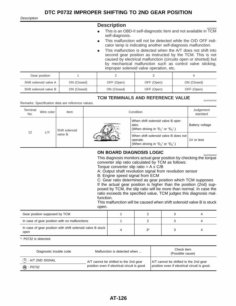
DescriptionNGAT0042
I This is an OBD-II self-diagnostic item and not available in TCMself-diagnosis.
I This malfunction will not be detected while the O/D OFF indi-cator lamp is indicating another self-diagnosis malfunction.
I This malfunction is detected when the A/T does not shift intosecond gear position as instructed by the TCM. This is notcaused by electrical malfunction (circuits open or shorted) butby mechanical malfunction such as control valve sticking,improper solenoid valve operation, etc.
Gear position 1 2 3 4
Shift solenoid valve A ON (Closed) OFF (Open) OFF (Open) ON (Closed)
Shift solenoid valve B ON (Closed) ON (Closed) OFF (Open) OFF (Open)
TCM TERMINALS AND REFERENCE VALUENGAT0042S02
Remarks: Specification data are reference values.
TerminalNo.
Wire color Item ConditionJudgementstandard
12 L/YShift solenoidvalve B
When shift solenoid valve B oper-ates.(When driving in “D1” or “D2”.)
Battery voltage
When shift solenoid valve B does notoperate.(When driving in “D3” or “D4”.)
1V or less
ON BOARD DIAGNOSIS LOGICNGAT0042S03
This diagnosis monitors actual gear position by checking the torqueconverter slip ratio calculated by TCM as follows:Torque converter slip ratio = A x C/BA: Output shaft revolution signal from revolution sensorB: Engine speed signal from ECMC: Gear ratio determined as gear position which TCM supposesIf the actual gear position is higher than the position (2nd) sup-posed by TCM, the slip ratio will be more than normal. In case theratio exceeds the specified value, TCM judges this diagnosis mal-function.This malfunction will be caused when shift solenoid valve B is stuckopen.
Gear position supposed by TCM 1 2 3 4
In case of gear position with no malfunctions 1 2 3 4
In case of gear position with shift solenoid valve B stuckopen
4 3* 3 4
*: P0732 is detected.
Diagnostic trouble code Malfunction is detected when ...Check item
(Possible cause)
: A/T 2ND SIGNAL A/T cannot be shifted to the 2nd gearposition even if electrical circuit is good.
A/T cannot be shifted to the 2nd gearposition even if electrical circuit is good.: P0732
DTC P0732 IMPROPER SHIFTING TO 2ND GEAR POSITIONDescription
AT-126
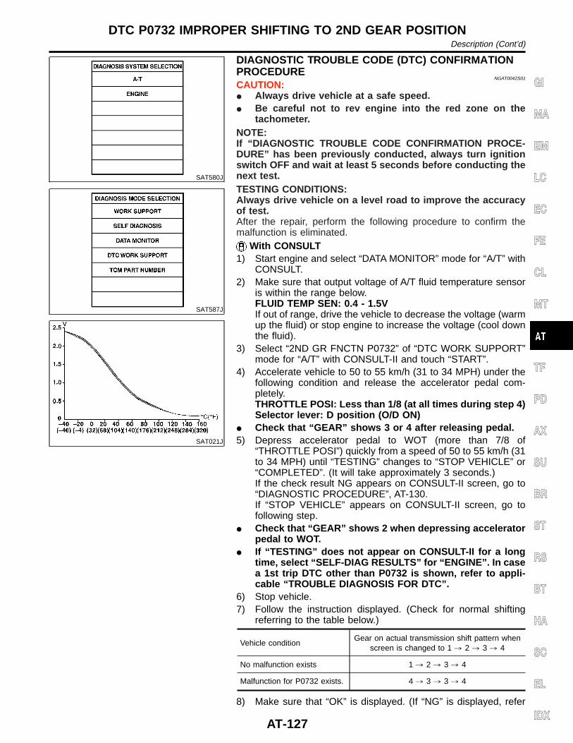
SAT580J
SAT587J
SAT021J
DIAGNOSTIC TROUBLE CODE (DTC) CONFIRMATIONPROCEDURE
NGAT0042S01
CAUTION:I Always drive vehicle at a safe speed.I Be careful not to rev engine into the red zone on the
tachometer.NOTE:If “DIAGNOSTIC TROUBLE CODE CONFIRMATION PROCE-DURE” has been previously conducted, always turn ignitionswitch OFF and wait at least 5 seconds before conducting thenext test.TESTING CONDITIONS:Always drive vehicle on a level road to improve the accuracyof test.After the repair, perform the following procedure to confirm themalfunction is eliminated.
With CONSULT1) Start engine and select “DATA MONITOR” mode for “A/T” with
CONSULT.2) Make sure that output voltage of A/T fluid temperature sensor
is within the range below.FLUID TEMP SEN: 0.4 - 1.5VIf out of range, drive the vehicle to decrease the voltage (warmup the fluid) or stop engine to increase the voltage (cool downthe fluid).
3) Select “2ND GR FNCTN P0732” of “DTC WORK SUPPORT”mode for “A/T” with CONSULT-II and touch “START”.
4) Accelerate vehicle to 50 to 55 km/h (31 to 34 MPH) under thefollowing condition and release the accelerator pedal com-pletely.THROTTLE POSI: Less than 1/8 (at all times during step 4)Selector lever: D position (O/D ON)
I Check that “GEAR” shows 3 or 4 after releasing pedal.5) Depress accelerator pedal to WOT (more than 7/8 of
“THROTTLE POSI”) quickly from a speed of 50 to 55 km/h (31to 34 MPH) until “TESTING” changes to “STOP VEHICLE” or“COMPLETED”. (It will take approximately 3 seconds.)If the check result NG appears on CONSULT-II screen, go to“DIAGNOSTIC PROCEDURE”, AT-130.If “STOP VEHICLE” appears on CONSULT-II screen, go tofollowing step.
I Check that “GEAR” shows 2 when depressing acceleratorpedal to WOT.
I If “TESTING” does not appear on CONSULT-II for a longtime, select “SELF-DIAG RESULTS” for “ENGINE”. In casea 1st trip DTC other than P0732 is shown, refer to appli-cable “TROUBLE DIAGNOSIS FOR DTC”.
6) Stop vehicle.7) Follow the instruction displayed. (Check for normal shifting
referring to the table below.)
Vehicle conditionGear on actual transmission shift pattern when
screen is changed to 1 , 2 , 3 , 4
No malfunction exists 1 , 2 , 3 , 4
Malfunction for P0732 exists. 4 , 3 , 3 , 4
8) Make sure that “OK” is displayed. (If “NG” is displayed, refer
GI
MA
EM
LC
EC
FE
CL
MT
TF
PD
AX
SU
BR
ST
RS
BT
HA
SC
EL
IDX
DTC P0732 IMPROPER SHIFTING TO 2ND GEAR POSITIONDescription (Cont’d)
AT-127

to “DIAGNOSTIC PROCEDURE”.) Refer to “DIAGNOSTICPROCEDURE”, AT-130. Refer to shift schedule, AT-338.
With GSTFollow the procedure “With CONSULT-II”.
DTC P0732 IMPROPER SHIFTING TO 2ND GEAR POSITIONDescription (Cont’d)
AT-128
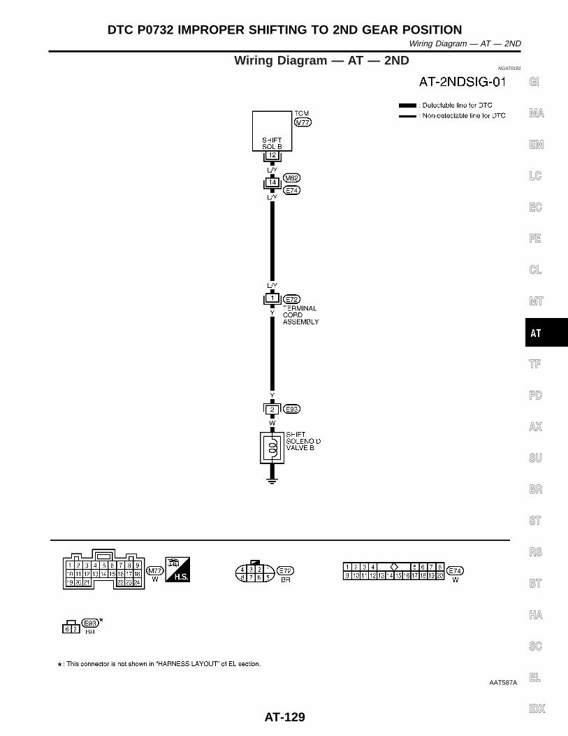
Wiring Diagram — AT — 2NDNGAT0191
AAT587A
GI
MA
EM
LC
EC
FE
CL
MT
TF
PD
AX
SU
BR
ST
RS
BT
HA
SC
EL
IDX
DTC P0732 IMPROPER SHIFTING TO 2ND GEAR POSITIONWiring Diagram — AT — 2ND
AT-129
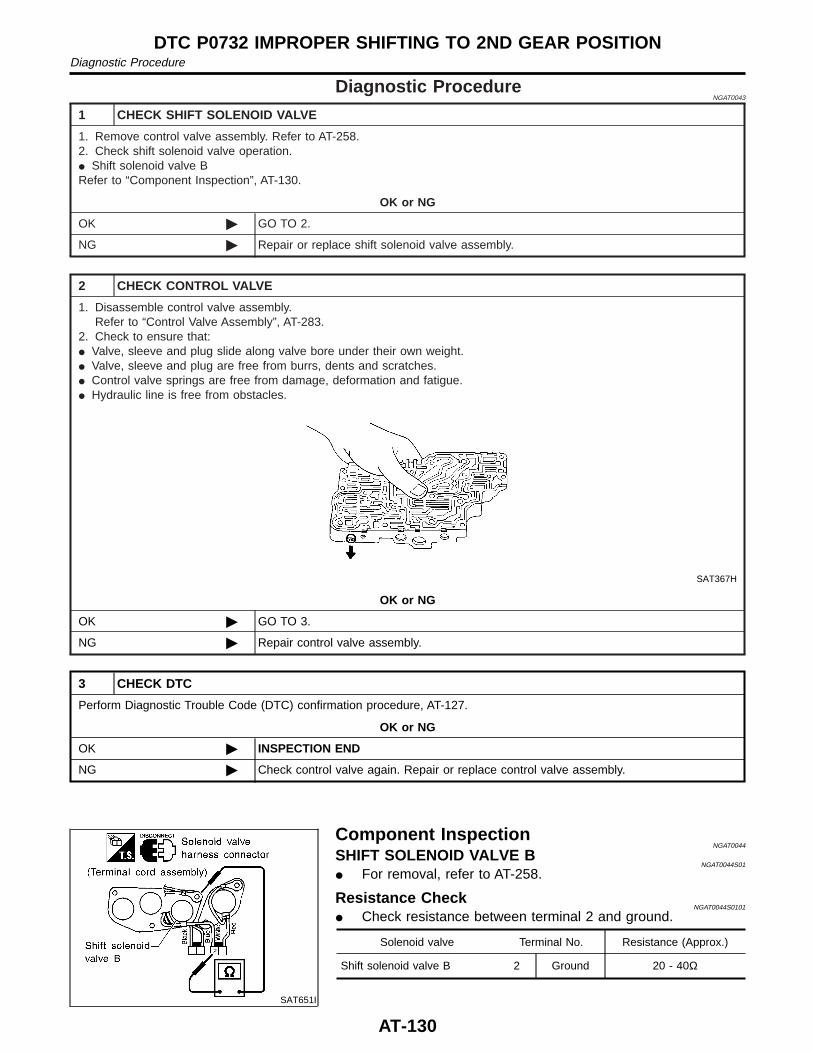
Diagnostic ProcedureNGAT0043
1 CHECK SHIFT SOLENOID VALVE
1. Remove control valve assembly. Refer to AT-258.2. Check shift solenoid valve operation.I Shift solenoid valve BRefer to “Component Inspection”, AT-130.
OK or NG
OK © GO TO 2.
NG © Repair or replace shift solenoid valve assembly.
2 CHECK CONTROL VALVE
1. Disassemble control valve assembly.Refer to “Control Valve Assembly”, AT-283.
2. Check to ensure that:I Valve, sleeve and plug slide along valve bore under their own weight.I Valve, sleeve and plug are free from burrs, dents and scratches.I Control valve springs are free from damage, deformation and fatigue.I Hydraulic line is free from obstacles.
SAT367H
OK or NG
OK © GO TO 3.
NG © Repair control valve assembly.
3 CHECK DTC
Perform Diagnostic Trouble Code (DTC) confirmation procedure, AT-127.
OK or NG
OK © INSPECTION END
NG © Check control valve again. Repair or replace control valve assembly.
SAT651I
Component InspectionNGAT0044
SHIFT SOLENOID VALVE BNGAT0044S01
I For removal, refer to AT-258.
Resistance CheckNGAT0044S0101
I Check resistance between terminal 2 and ground.
Solenoid valve Terminal No. Resistance (Approx.)
Shift solenoid valve B 2 Ground 20 - 40Ω
DTC P0732 IMPROPER SHIFTING TO 2ND GEAR POSITIONDiagnostic Procedure
AT-130
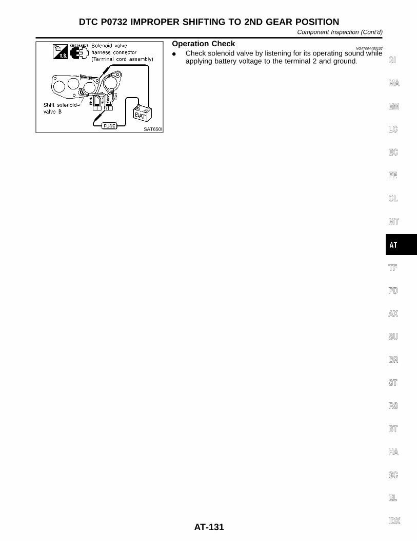
SAT650I
Operation CheckNGAT0044S0102
I Check solenoid valve by listening for its operating sound whileapplying battery voltage to the terminal 2 and ground. GI
MA
EM
LC
EC
FE
CL
MT
TF
PD
AX
SU
BR
ST
RS
BT
HA
SC
EL
IDX
DTC P0732 IMPROPER SHIFTING TO 2ND GEAR POSITIONComponent Inspection (Cont’d)
AT-131
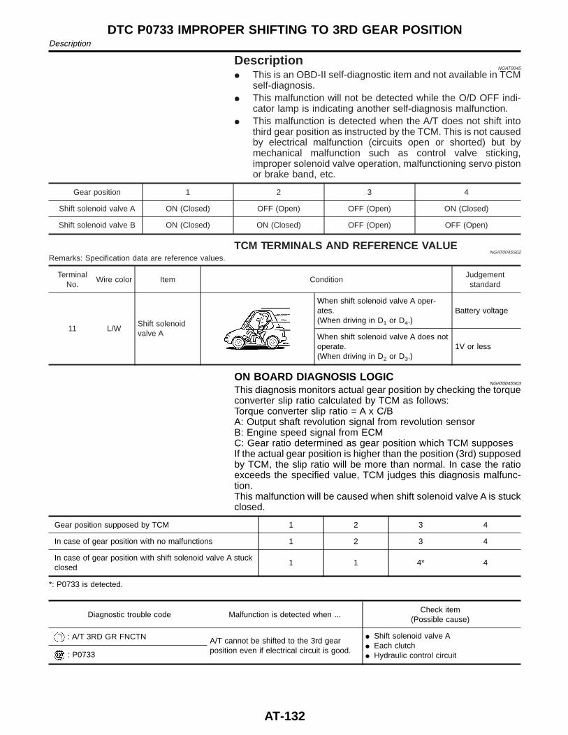
DescriptionNGAT0045
I This is an OBD-II self-diagnostic item and not available in TCMself-diagnosis.
I This malfunction will not be detected while the O/D OFF indi-cator lamp is indicating another self-diagnosis malfunction.
I This malfunction is detected when the A/T does not shift intothird gear position as instructed by the TCM. This is not causedby electrical malfunction (circuits open or shorted) but bymechanical malfunction such as control valve sticking,improper solenoid valve operation, malfunctioning servo pistonor brake band, etc.
Gear position 1 2 3 4
Shift solenoid valve A ON (Closed) OFF (Open) OFF (Open) ON (Closed)
Shift solenoid valve B ON (Closed) ON (Closed) OFF (Open) OFF (Open)
TCM TERMINALS AND REFERENCE VALUENGAT0045S02
Remarks: Specification data are reference values.
TerminalNo.
Wire color Item ConditionJudgementstandard
11 L/WShift solenoidvalve A
When shift solenoid valve A oper-ates.(When driving in D1 or D4.)
Battery voltage
When shift solenoid valve A does notoperate.(When driving in D2 or D3.)
1V or less
ON BOARD DIAGNOSIS LOGICNGAT0045S03
This diagnosis monitors actual gear position by checking the torqueconverter slip ratio calculated by TCM as follows:Torque converter slip ratio = A x C/BA: Output shaft revolution signal from revolution sensorB: Engine speed signal from ECMC: Gear ratio determined as gear position which TCM supposesIf the actual gear position is higher than the position (3rd) supposedby TCM, the slip ratio will be more than normal. In case the ratioexceeds the specified value, TCM judges this diagnosis malfunc-tion.This malfunction will be caused when shift solenoid valve A is stuckclosed.
Gear position supposed by TCM 1 2 3 4
In case of gear position with no malfunctions 1 2 3 4
In case of gear position with shift solenoid valve A stuckclosed
1 1 4* 4
*: P0733 is detected.
Diagnostic trouble code Malfunction is detected when ...Check item
(Possible cause)
: A/T 3RD GR FNCTN A/T cannot be shifted to the 3rd gearposition even if electrical circuit is good.
I Shift solenoid valve AI Each clutchI Hydraulic control circuit: P0733
DTC P0733 IMPROPER SHIFTING TO 3RD GEAR POSITIONDescription
AT-132
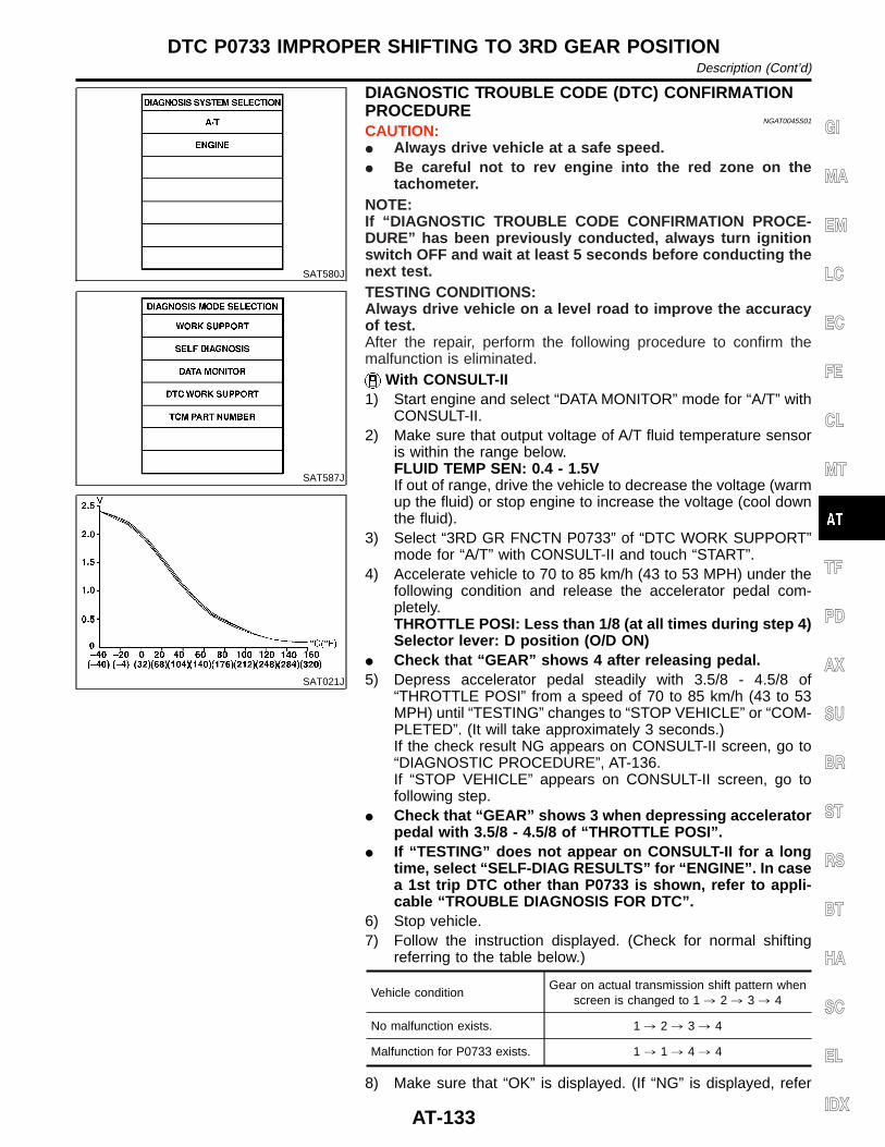
SAT580J
SAT587J
SAT021J
DIAGNOSTIC TROUBLE CODE (DTC) CONFIRMATIONPROCEDURE
NGAT0045S01
CAUTION:I Always drive vehicle at a safe speed.I Be careful not to rev engine into the red zone on the
tachometer.NOTE:If “DIAGNOSTIC TROUBLE CODE CONFIRMATION PROCE-DURE” has been previously conducted, always turn ignitionswitch OFF and wait at least 5 seconds before conducting thenext test.TESTING CONDITIONS:Always drive vehicle on a level road to improve the accuracyof test.After the repair, perform the following procedure to confirm themalfunction is eliminated.
With CONSULT-II1) Start engine and select “DATA MONITOR” mode for “A/T” with
CONSULT-II.2) Make sure that output voltage of A/T fluid temperature sensor
is within the range below.FLUID TEMP SEN: 0.4 - 1.5VIf out of range, drive the vehicle to decrease the voltage (warmup the fluid) or stop engine to increase the voltage (cool downthe fluid).
3) Select “3RD GR FNCTN P0733” of “DTC WORK SUPPORT”mode for “A/T” with CONSULT-II and touch “START”.
4) Accelerate vehicle to 70 to 85 km/h (43 to 53 MPH) under thefollowing condition and release the accelerator pedal com-pletely.THROTTLE POSI: Less than 1/8 (at all times during step 4)Selector lever: D position (O/D ON)
I Check that “GEAR” shows 4 after releasing pedal.5) Depress accelerator pedal steadily with 3.5/8 - 4.5/8 of
“THROTTLE POSI” from a speed of 70 to 85 km/h (43 to 53MPH) until “TESTING” changes to “STOP VEHICLE” or “COM-PLETED”. (It will take approximately 3 seconds.)If the check result NG appears on CONSULT-II screen, go to“DIAGNOSTIC PROCEDURE”, AT-136.If “STOP VEHICLE” appears on CONSULT-II screen, go tofollowing step.
I Check that “GEAR” shows 3 when depressing acceleratorpedal with 3.5/8 - 4.5/8 of “THROTTLE POSI”.
I If “TESTING” does not appear on CONSULT-II for a longtime, select “SELF-DIAG RESULTS” for “ENGINE”. In casea 1st trip DTC other than P0733 is shown, refer to appli-cable “TROUBLE DIAGNOSIS FOR DTC”.
6) Stop vehicle.7) Follow the instruction displayed. (Check for normal shifting
referring to the table below.)
Vehicle conditionGear on actual transmission shift pattern when
screen is changed to 1 , 2 , 3 , 4
No malfunction exists. 1 , 2 , 3 , 4
Malfunction for P0733 exists. 1 , 1 , 4 , 4
8) Make sure that “OK” is displayed. (If “NG” is displayed, refer
GI
MA
EM
LC
EC
FE
CL
MT
TF
PD
AX
SU
BR
ST
RS
BT
HA
SC
EL
IDX
DTC P0733 IMPROPER SHIFTING TO 3RD GEAR POSITIONDescription (Cont’d)
AT-133

to “DIAGNOSTIC PROCEDURE”.) Refer to “DIAGNOSTICPROCEDURE”, AT-136.Refer to shift schedule, AT-338.
With GSTFollow the procedure “With CONSULT-II”.
DTC P0733 IMPROPER SHIFTING TO 3RD GEAR POSITIONDescription (Cont’d)
AT-134
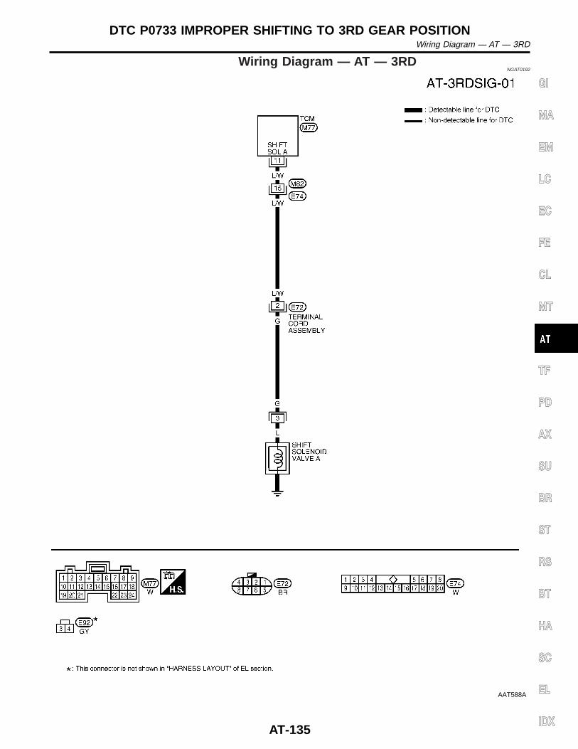
Wiring Diagram — AT — 3RDNGAT0192
AAT588A
GI
MA
EM
LC
EC
FE
CL
MT
TF
PD
AX
SU
BR
ST
RS
BT
HA
SC
EL
IDX
DTC P0733 IMPROPER SHIFTING TO 3RD GEAR POSITIONWiring Diagram — AT — 3RD
AT-135
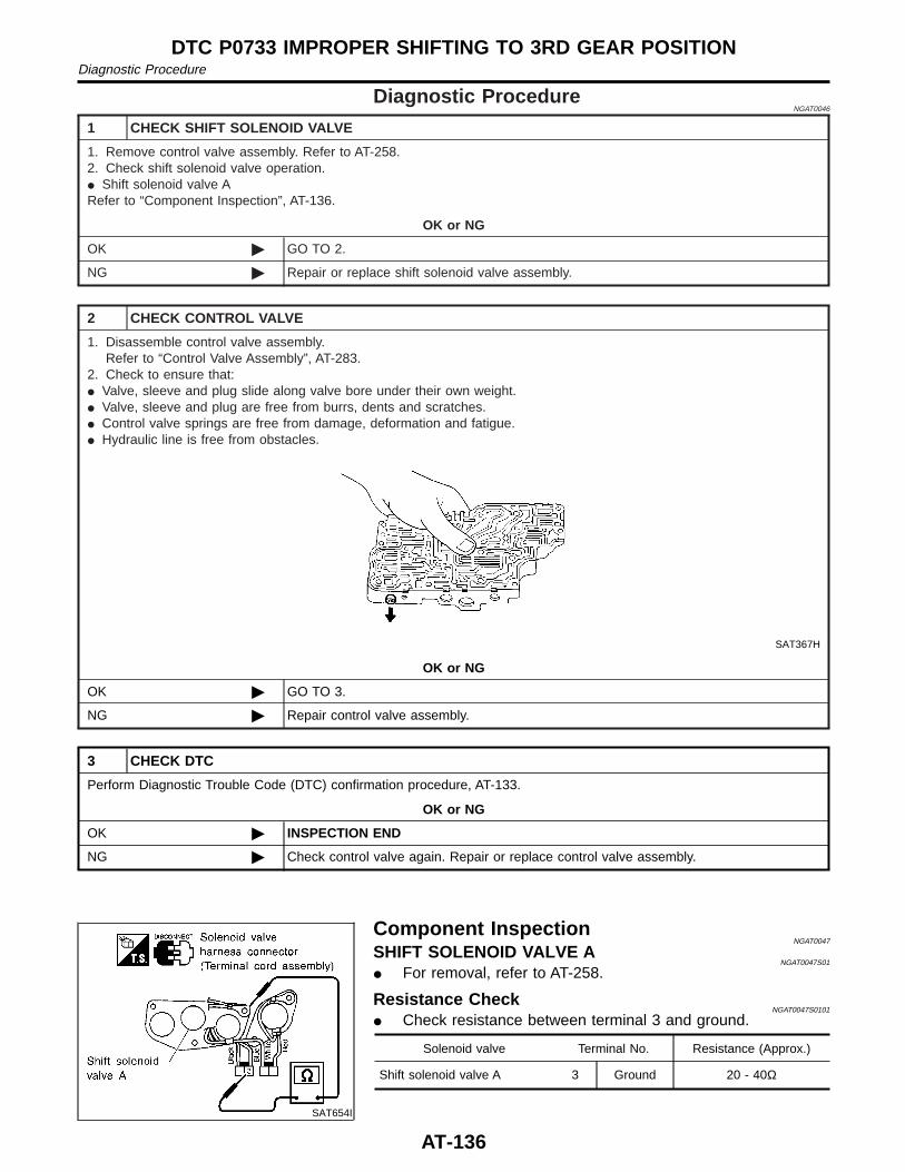
Diagnostic ProcedureNGAT0046
1 CHECK SHIFT SOLENOID VALVE
1. Remove control valve assembly. Refer to AT-258.2. Check shift solenoid valve operation.I Shift solenoid valve ARefer to “Component Inspection”, AT-136.
OK or NG
OK © GO TO 2.
NG © Repair or replace shift solenoid valve assembly.
2 CHECK CONTROL VALVE
1. Disassemble control valve assembly.Refer to “Control Valve Assembly”, AT-283.
2. Check to ensure that:I Valve, sleeve and plug slide along valve bore under their own weight.I Valve, sleeve and plug are free from burrs, dents and scratches.I Control valve springs are free from damage, deformation and fatigue.I Hydraulic line is free from obstacles.
SAT367H
OK or NG
OK © GO TO 3.
NG © Repair control valve assembly.
3 CHECK DTC
Perform Diagnostic Trouble Code (DTC) confirmation procedure, AT-133.
OK or NG
OK © INSPECTION END
NG © Check control valve again. Repair or replace control valve assembly.
SAT654I
Component InspectionNGAT0047
SHIFT SOLENOID VALVE ANGAT0047S01
I For removal, refer to AT-258.
Resistance CheckNGAT0047S0101
I Check resistance between terminal 3 and ground.
Solenoid valve Terminal No. Resistance (Approx.)
Shift solenoid valve A 3 Ground 20 - 40Ω
DTC P0733 IMPROPER SHIFTING TO 3RD GEAR POSITIONDiagnostic Procedure
AT-136

SAT653I
Operation CheckNGAT0047S0102
I Check solenoid valve by listening for its operating sound whileapplying battery voltage to the terminal 3 and ground. GI
MA
EM
LC
EC
FE
CL
MT
TF
PD
AX
SU
BR
ST
RS
BT
HA
SC
EL
IDX
DTC P0733 IMPROPER SHIFTING TO 3RD GEAR POSITIONComponent Inspection (Cont’d)
AT-137
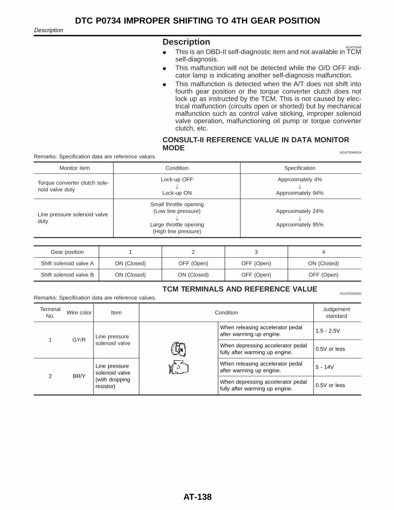
DescriptionNGAT0048
I This is an OBD-II self-diagnostic item and not available in TCMself-diagnosis.
I This malfunction will not be detected while the O/D OFF indi-cator lamp is indicating another self-diagnosis malfunction.
I This malfunction is detected when the A/T does not shift intofourth gear position or the torque converter clutch does notlock up as instructed by the TCM. This is not caused by elec-trical malfunction (circuits open or shorted) but by mechanicalmalfunction such as control valve sticking, improper solenoidvalve operation, malfunctioning oil pump or torque converterclutch, etc.
CONSULT-II REFERENCE VALUE IN DATA MONITORMODE
NGAT0048S04
Remarks: Specification data are reference values.
Monitor item Condition Specification
Torque converter clutch sole-noid valve duty
Lock-up OFF"
Lock-up ON
Approximately 4%"
Approximately 94%
Line pressure solenoid valveduty
Small throttle opening(Low line pressure)
"
Large throttle opening(High line pressure)
Approximately 24%"
Approximately 95%
Gear position 1 2 3 4
Shift solenoid valve A ON (Closed) OFF (Open) OFF (Open) ON (Closed)
Shift solenoid valve B ON (Closed) ON (Closed) OFF (Open) OFF (Open)
TCM TERMINALS AND REFERENCE VALUENGAT0048S02
Remarks: Specification data are reference values.
TerminalNo.
Wire color Item ConditionJudgementstandard
1 GY/RLine pressuresolenoid valve
When releasing accelerator pedalafter warming up engine.
1.5 - 2.5V
When depressing accelerator pedalfully after warming up engine.
0.5V or less
2 BR/Y
Line pressuresolenoid valve(with droppingresistor)
When releasing accelerator pedalafter warming up engine.
5 - 14V
When depressing accelerator pedalfully after warming up engine.
0.5V or less
DTC P0734 IMPROPER SHIFTING TO 4TH GEAR POSITIONDescription
AT-138
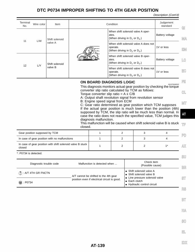
TerminalNo.
Wire color Item ConditionJudgementstandard
11 L/WShift solenoidvalve A
When shift solenoid valve A oper-ates.(When driving in D1 or D4.)
Battery voltage
When shift solenoid valve A does notoperate.(When driving in D2 or D3.)
1V or less
12 L/YShift solenoidvalve B
When shift solenoid valve B oper-ates.(When driving in D1 or D2.)
Battery voltage
When shift solenoid valve B does notoperate.(When driving in D3 or D4.)
1V or less
ON BOARD DIAGNOSIS LOGICNGAT0048S03
This diagnosis monitors actual gear position by checking the torqueconverter slip ratio calculated by TCM as follows:Torque converter slip ratio = A x C/BA: Output shaft revolution signal from revolution sensorB: Engine speed signal from ECMC: Gear ratio determined as gear position which TCM supposesIf the actual gear position is much lower than the position (4th)supposed by TCM, the slip ratio will be much less than normal. Incase the ratio does not reach the specified value, TCM judges thisdiagnosis malfunction.This malfunction will be caused when shift solenoid valve B is stuckclosed.
Gear position supposed by TCM 1 2 3 4
In case of gear position with no malfunctions 1 2 3 4
In case of gear position with shift solenoid valve B stuckclosed
1 2 2 1*
*: P0734 is detected.
Diagnostic trouble code Malfunction is detected when ...Check item
(Possible cause)
: A/T 4TH GR FNCTNA/T cannot be shifted to the 4th gearposition even if electrical circuit is good.
I Shift solenoid valve AI Shift solenoid valve BI Line pressure solenoid valveI Each clutchI Hydraulic control circuit
: P0734
GI
MA
EM
LC
EC
FE
CL
MT
TF
PD
AX
SU
BR
ST
RS
BT
HA
SC
EL
IDX
DTC P0734 IMPROPER SHIFTING TO 4TH GEAR POSITIONDescription (Cont’d)
AT-139
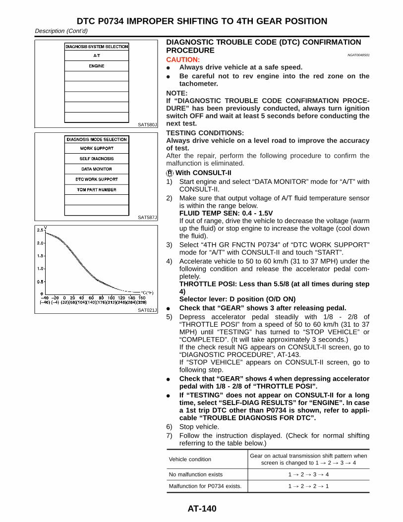
SAT580J
SAT587J
SAT021J
DIAGNOSTIC TROUBLE CODE (DTC) CONFIRMATIONPROCEDURE
NGAT0048S01
CAUTION:I Always drive vehicle at a safe speed.I Be careful not to rev engine into the red zone on the
tachometer.NOTE:If “DIAGNOSTIC TROUBLE CODE CONFIRMATION PROCE-DURE” has been previously conducted, always turn ignitionswitch OFF and wait at least 5 seconds before conducting thenext test.TESTING CONDITIONS:Always drive vehicle on a level road to improve the accuracyof test.After the repair, perform the following procedure to confirm themalfunction is eliminated.
With CONSULT-II1) Start engine and select “DATA MONITOR” mode for “A/T” with
CONSULT-II.2) Make sure that output voltage of A/T fluid temperature sensor
is within the range below.FLUID TEMP SEN: 0.4 - 1.5VIf out of range, drive the vehicle to decrease the voltage (warmup the fluid) or stop engine to increase the voltage (cool downthe fluid).
3) Select “4TH GR FNCTN P0734” of “DTC WORK SUPPORT”mode for “A/T” with CONSULT-II and touch “START”.
4) Accelerate vehicle to 50 to 60 km/h (31 to 37 MPH) under thefollowing condition and release the accelerator pedal com-pletely.THROTTLE POSI: Less than 5.5/8 (at all times during step4)Selector lever: D position (O/D ON)
I Check that “GEAR” shows 3 after releasing pedal.5) Depress accelerator pedal steadily with 1/8 - 2/8 of
“THROTTLE POSI” from a speed of 50 to 60 km/h (31 to 37MPH) until “TESTING” has turned to “STOP VEHICLE” or“COMPLETED”. (It will take approximately 3 seconds.)If the check result NG appears on CONSULT-II screen, go to“DIAGNOSTIC PROCEDURE”, AT-143.If “STOP VEHICLE” appears on CONSULT-II screen, go tofollowing step.
I Check that “GEAR” shows 4 when depressing acceleratorpedal with 1/8 - 2/8 of “THROTTLE POSI”.
I If “TESTING” does not appear on CONSULT-II for a longtime, select “SELF-DIAG RESULTS” for “ENGINE”. In casea 1st trip DTC other than P0734 is shown, refer to appli-cable “TROUBLE DIAGNOSIS FOR DTC”.
6) Stop vehicle.7) Follow the instruction displayed. (Check for normal shifting
referring to the table below.)
Vehicle conditionGear on actual transmission shift pattern when
screen is changed to 1 , 2 , 3 , 4
No malfunction exists 1 , 2 , 3 , 4
Malfunction for P0734 exists. 1 , 2 , 2 , 1
DTC P0734 IMPROPER SHIFTING TO 4TH GEAR POSITIONDescription (Cont’d)
AT-140
8) Make sure that “OK” is displayed. (If “NG” is displayed, referto “DIAGNOSTIC PROCEDURE”.) Refer to “DIAGNOSTICPROCEDURE”, AT-143.Refer to shift schedule, AT-338.
With GSTFollow the procedure “With CONSULT-II”.
GI
MA
EM
LC
EC
FE
CL
MT
TF
PD
AX
SU
BR
ST
RS
BT
HA
SC
EL
IDX
DTC P0734 IMPROPER SHIFTING TO 4TH GEAR POSITIONDescription (Cont’d)
AT-141
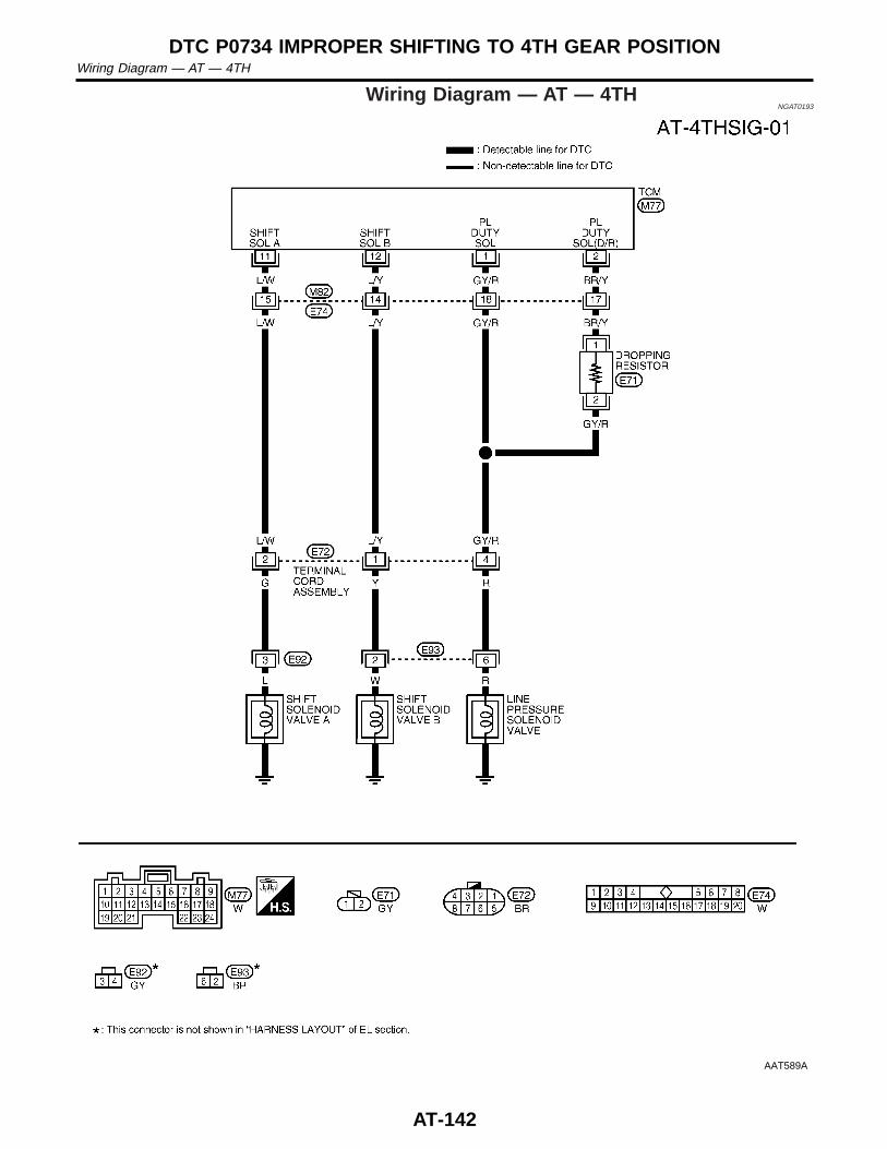
Wiring Diagram — AT — 4THNGAT0193
AAT589A
DTC P0734 IMPROPER SHIFTING TO 4TH GEAR POSITIONWiring Diagram — AT — 4TH
AT-142
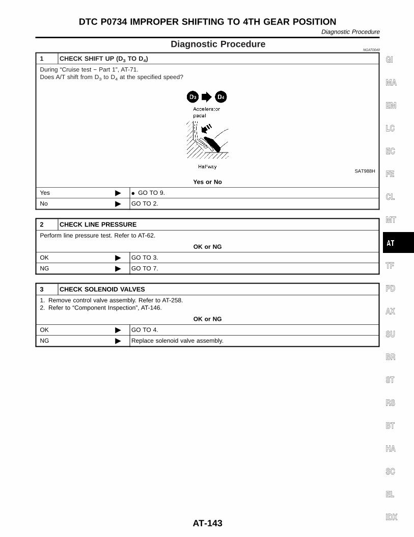
Diagnostic ProcedureNGAT0049
1 CHECK SHIFT UP (D3 TO D4)
During “Cruise test − Part 1”, AT-71.Does A/T shift from D3 to D4 at the specified speed?
SAT988H
Yes or No
Yes © I GO TO 9.
No © GO TO 2.
2 CHECK LINE PRESSURE
Perform line pressure test. Refer to AT-62.
OK or NG
OK © GO TO 3.
NG © GO TO 7.
3 CHECK SOLENOID VALVES
1. Remove control valve assembly. Refer to AT-258.2. Refer to “Component Inspection”, AT-146.
OK or NG
OK © GO TO 4.
NG © Replace solenoid valve assembly.
GI
MA
EM
LC
EC
FE
CL
MT
TF
PD
AX
SU
BR
ST
RS
BT
HA
SC
EL
IDX
DTC P0734 IMPROPER SHIFTING TO 4TH GEAR POSITIONDiagnostic Procedure
AT-143
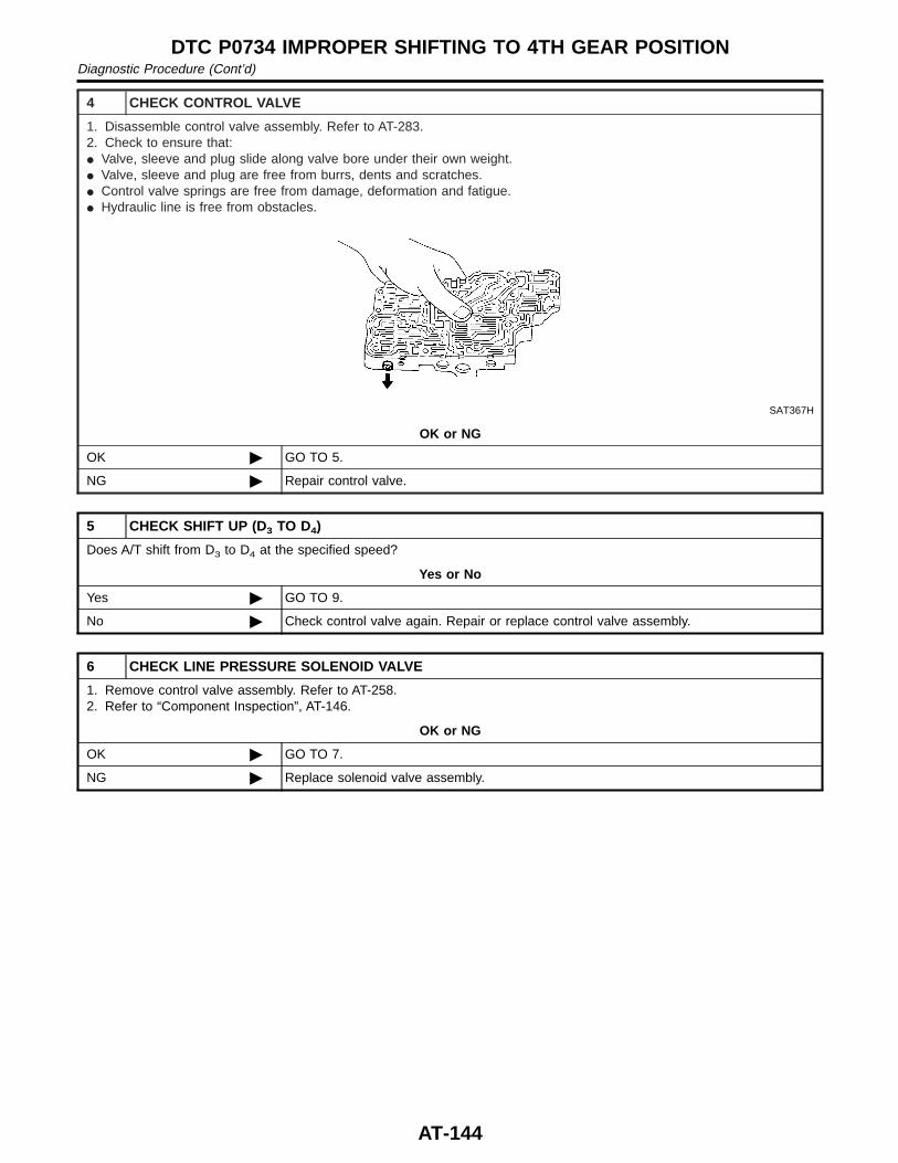
4 CHECK CONTROL VALVE
1. Disassemble control valve assembly. Refer to AT-283.2. Check to ensure that:I Valve, sleeve and plug slide along valve bore under their own weight.I Valve, sleeve and plug are free from burrs, dents and scratches.I Control valve springs are free from damage, deformation and fatigue.I Hydraulic line is free from obstacles.
SAT367H
OK or NG
OK © GO TO 5.
NG © Repair control valve.
5 CHECK SHIFT UP (D3 TO D4)
Does A/T shift from D3 to D4 at the specified speed?
Yes or No
Yes © GO TO 9.
No © Check control valve again. Repair or replace control valve assembly.
6 CHECK LINE PRESSURE SOLENOID VALVE
1. Remove control valve assembly. Refer to AT-258.2. Refer to “Component Inspection”, AT-146.
OK or NG
OK © GO TO 7.
NG © Replace solenoid valve assembly.
DTC P0734 IMPROPER SHIFTING TO 4TH GEAR POSITIONDiagnostic Procedure (Cont’d)
AT-144
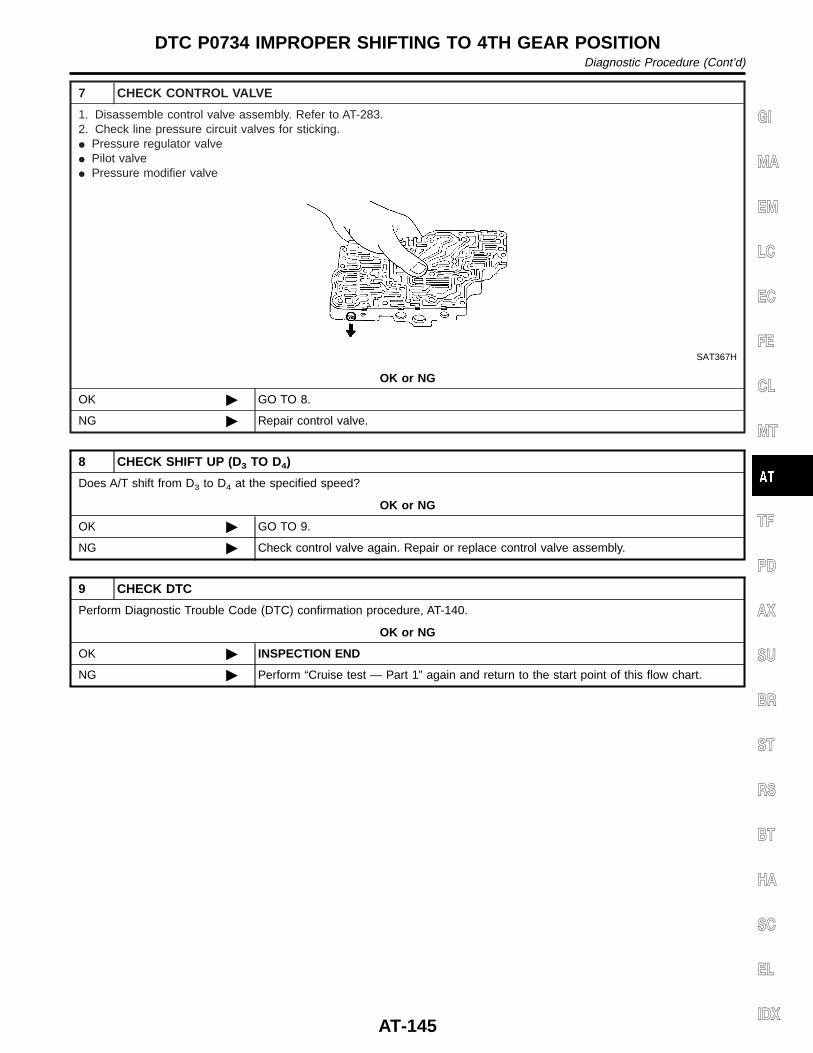
7 CHECK CONTROL VALVE
1. Disassemble control valve assembly. Refer to AT-283.2. Check line pressure circuit valves for sticking.I Pressure regulator valveI Pilot valveI Pressure modifier valve
SAT367H
OK or NG
OK © GO TO 8.
NG © Repair control valve.
8 CHECK SHIFT UP (D3 TO D4)
Does A/T shift from D3 to D4 at the specified speed?
OK or NG
OK © GO TO 9.
NG © Check control valve again. Repair or replace control valve assembly.
9 CHECK DTC
Perform Diagnostic Trouble Code (DTC) confirmation procedure, AT-140.
OK or NG
OK © INSPECTION END
NG © Perform “Cruise test — Part 1” again and return to the start point of this flow chart.
GI
MA
EM
LC
EC
FE
CL
MT
TF
PD
AX
SU
BR
ST
RS
BT
HA
SC
EL
IDX
DTC P0734 IMPROPER SHIFTING TO 4TH GEAR POSITIONDiagnostic Procedure (Cont’d)
AT-145
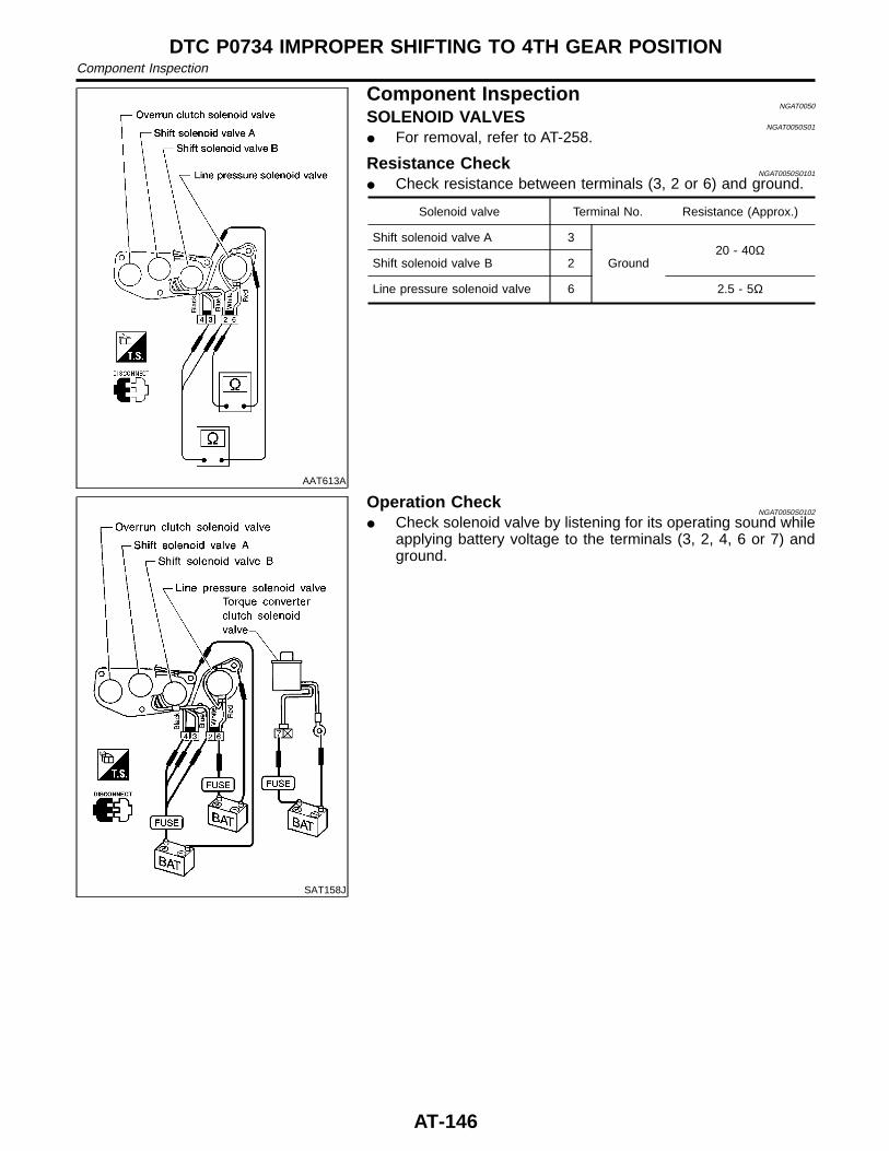
AAT613A
Component InspectionNGAT0050
SOLENOID VALVESNGAT0050S01
I For removal, refer to AT-258.
Resistance CheckNGAT0050S0101
I Check resistance between terminals (3, 2 or 6) and ground.
Solenoid valve Terminal No. Resistance (Approx.)
Shift solenoid valve A 3
Ground20 - 40Ω
Shift solenoid valve B 2
Line pressure solenoid valve 6 2.5 - 5Ω
SAT158J
Operation CheckNGAT0050S0102
I Check solenoid valve by listening for its operating sound whileapplying battery voltage to the terminals (3, 2, 4, 6 or 7) andground.
DTC P0734 IMPROPER SHIFTING TO 4TH GEAR POSITIONComponent Inspection
AT-146
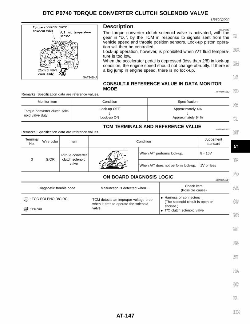
SAT342HA
DescriptionNGAT0051
The torque converter clutch solenoid valve is activated, with thegear in “D4”, by the TCM in response to signals sent from thevehicle speed and throttle position sensors. Lock-up piston opera-tion will then be controlled.Lock-up operation, however, is prohibited when A/T fluid tempera-ture is too low.When the accelerator pedal is depressed (less than 2/8) in lock-upcondition, the engine speed should not change abruptly. If there isa big jump in engine speed, there is no lock-up.
CONSULT-II REFERENCE VALUE IN DATA MONITORMODE
NGAT0051S02
Remarks: Specification data are reference values.
Monitor item Condition Specification
Torque converter clutch sole-noid valve duty
Lock-up OFF"
Lock-up ON
Approximately 4%"
Approximately 94%
TCM TERMINALS AND REFERENCE VALUENGAT0051S03
Remarks: Specification data are reference values.
TerminalNo.
Wire color Item ConditionJudgementstandard
3 G/ORTorque converterclutch solenoid
valve
When A/T performs lock-up. 8 - 15V
When A/T does not perform lock-up. 1V or less
ON BOARD DIAGNOSIS LOGICNGAT0051S04
Diagnostic trouble code Malfunction is detected when ...Check item
(Possible cause)
: TCC SOLENOID/CIRC TCM detects an improper voltage dropwhen it tires to operate the solenoidvalve.
I Harness or connectors(The solenoid circuit is open orshorted.)
I T/C clutch solenoid valve: P0740
GI
MA
EM
LC
EC
FE
CL
MT
TF
PD
AX
SU
BR
ST
RS
BT
HA
SC
EL
IDX
DTC P0740 TORQUE CONVERTER CLUTCH SOLENOID VALVEDescription
AT-147
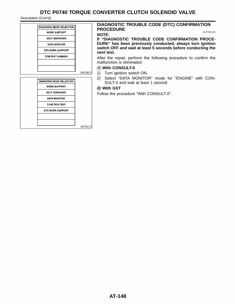
SAT587J
SAT617J
DIAGNOSTIC TROUBLE CODE (DTC) CONFIRMATIONPROCEDURE
NGAT0051S01
NOTE:If “DIAGNOSTIC TROUBLE CODE CONFIRMATION PROCE-DURE” has been previously conducted, always turn ignitionswitch OFF and wait at least 5 seconds before conducting thenext test.After the repair, perform the following procedure to confirm themalfunction is eliminated.
With CONSULT-II1) Turn ignition switch ON.2) Select “DATA MONITOR” mode for “ENGINE” with CON-
SULT-II and wait at least 1 second.With GST
Follow the procedure “With CONSULT-II”.
DTC P0740 TORQUE CONVERTER CLUTCH SOLENOID VALVEDescription (Cont’d)
AT-148
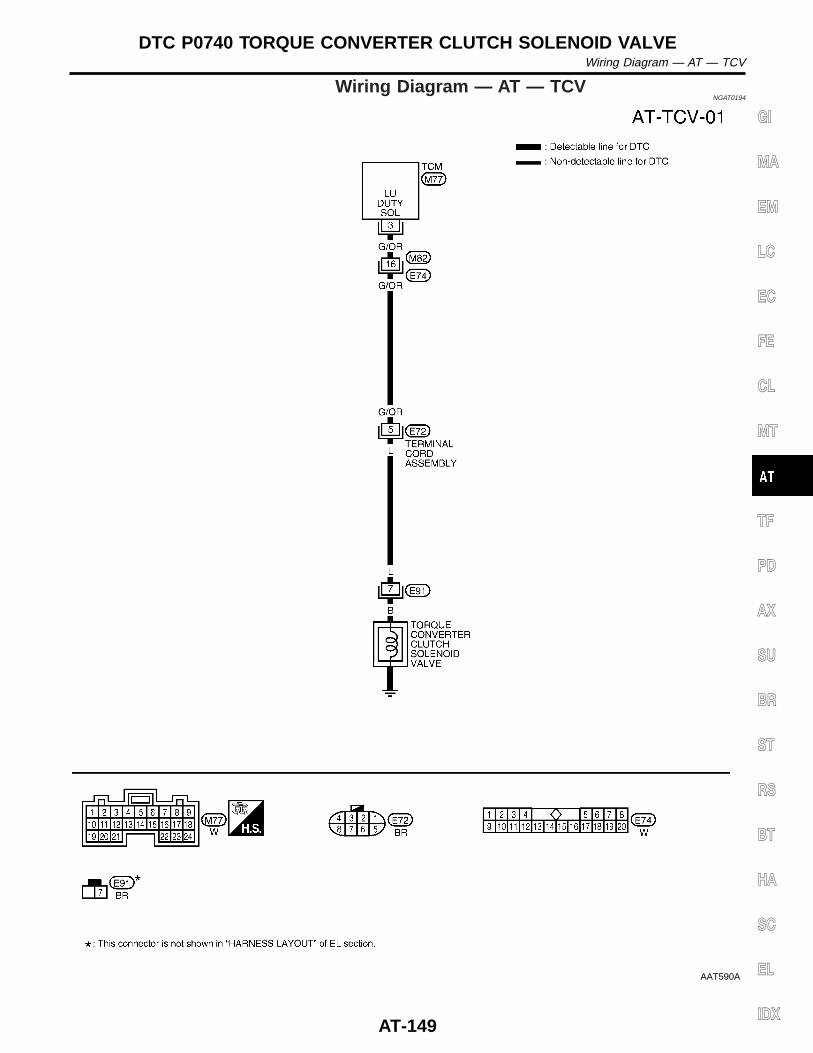
Wiring Diagram — AT — TCVNGAT0194
AAT590A
GI
MA
EM
LC
EC
FE
CL
MT
TF
PD
AX
SU
BR
ST
RS
BT
HA
SC
EL
IDX
DTC P0740 TORQUE CONVERTER CLUTCH SOLENOID VALVEWiring Diagram — AT — TCV
AT-149
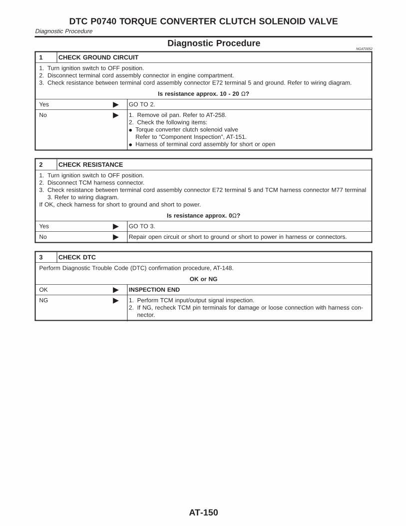
Diagnostic ProcedureNGAT0052
1 CHECK GROUND CIRCUIT
1. Turn ignition switch to OFF position.2. Disconnect terminal cord assembly connector in engine compartment.3. Check resistance between terminal cord assembly connector E72 terminal 5 and ground. Refer to wiring diagram.
Is resistance approx. 10 - 20 Ω?
Yes © GO TO 2.
No © 1. Remove oil pan. Refer to AT-258.2. Check the following items:I Torque converter clutch solenoid valve
Refer to “Component Inspection”, AT-151.I Harness of terminal cord assembly for short or open
2 CHECK RESISTANCE
1. Turn ignition switch to OFF position.2. Disconnect TCM harness connector.3. Check resistance between terminal cord assembly connector E72 terminal 5 and TCM harness connector M77 terminal
3. Refer to wiring diagram.If OK, check harness for short to ground and short to power.
Is resistance approx. 0 Ω?
Yes © GO TO 3.
No © Repair open circuit or short to ground or short to power in harness or connectors.
3 CHECK DTC
Perform Diagnostic Trouble Code (DTC) confirmation procedure, AT-148.
OK or NG
OK © INSPECTION END
NG © 1. Perform TCM input/output signal inspection.2. If NG, recheck TCM pin terminals for damage or loose connection with harness con-
nector.
DTC P0740 TORQUE CONVERTER CLUTCH SOLENOID VALVEDiagnostic Procedure
AT-150
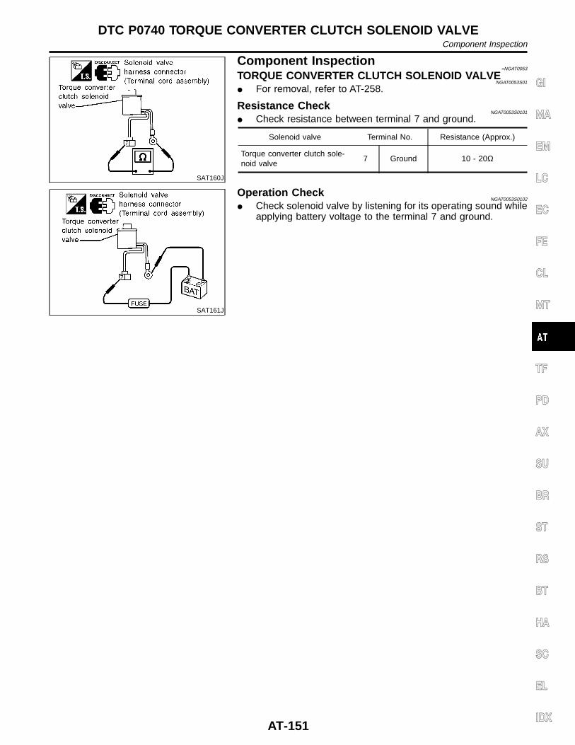
SAT160J
Component Inspection=NGAT0053
TORQUE CONVERTER CLUTCH SOLENOID VALVENGAT0053S01
I For removal, refer to AT-258.
Resistance CheckNGAT0053S0101
I Check resistance between terminal 7 and ground.
Solenoid valve Terminal No. Resistance (Approx.)
Torque converter clutch sole-noid valve
7 Ground 10 - 20Ω
SAT161J
Operation CheckNGAT0053S0102
I Check solenoid valve by listening for its operating sound whileapplying battery voltage to the terminal 7 and ground.
GI
MA
EM
LC
EC
FE
CL
MT
TF
PD
AX
SU
BR
ST
RS
BT
HA
SC
EL
IDX
DTC P0740 TORQUE CONVERTER CLUTCH SOLENOID VALVEComponent Inspection
AT-151
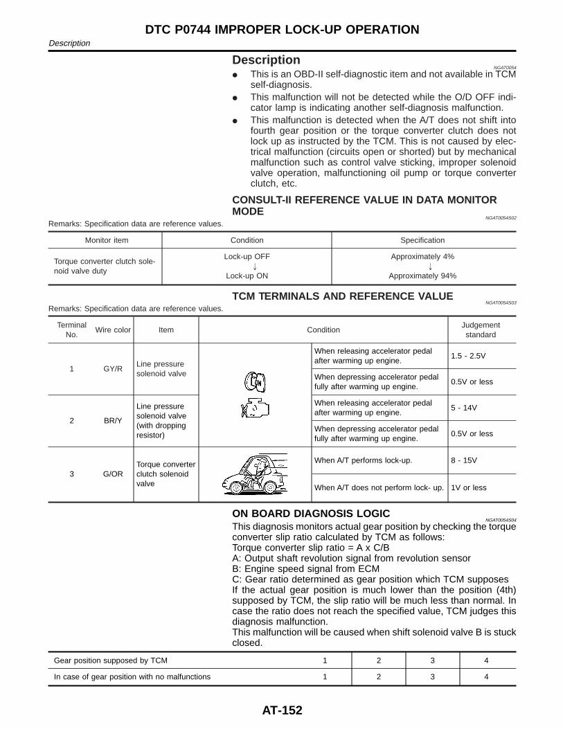
DescriptionNGAT0054
I This is an OBD-II self-diagnostic item and not available in TCMself-diagnosis.
I This malfunction will not be detected while the O/D OFF indi-cator lamp is indicating another self-diagnosis malfunction.
I This malfunction is detected when the A/T does not shift intofourth gear position or the torque converter clutch does notlock up as instructed by the TCM. This is not caused by elec-trical malfunction (circuits open or shorted) but by mechanicalmalfunction such as control valve sticking, improper solenoidvalve operation, malfunctioning oil pump or torque converterclutch, etc.
CONSULT-II REFERENCE VALUE IN DATA MONITORMODE
NGAT0054S02
Remarks: Specification data are reference values.
Monitor item Condition Specification
Torque converter clutch sole-noid valve duty
Lock-up OFF"
Lock-up ON
Approximately 4%"
Approximately 94%
TCM TERMINALS AND REFERENCE VALUENGAT0054S03
Remarks: Specification data are reference values.
TerminalNo.
Wire color Item ConditionJudgementstandard
1 GY/RLine pressuresolenoid valve
When releasing accelerator pedalafter warming up engine.
1.5 - 2.5V
When depressing accelerator pedalfully after warming up engine.
0.5V or less
2 BR/Y
Line pressuresolenoid valve(with droppingresistor)
When releasing accelerator pedalafter warming up engine.
5 - 14V
When depressing accelerator pedalfully after warming up engine.
0.5V or less
3 G/ORTorque converterclutch solenoidvalve
When A/T performs lock-up. 8 - 15V
When A/T does not perform lock- up. 1V or less
ON BOARD DIAGNOSIS LOGICNGAT0054S04
This diagnosis monitors actual gear position by checking the torqueconverter slip ratio calculated by TCM as follows:Torque converter slip ratio = A x C/BA: Output shaft revolution signal from revolution sensorB: Engine speed signal from ECMC: Gear ratio determined as gear position which TCM supposesIf the actual gear position is much lower than the position (4th)supposed by TCM, the slip ratio will be much less than normal. Incase the ratio does not reach the specified value, TCM judges thisdiagnosis malfunction.This malfunction will be caused when shift solenoid valve B is stuckclosed.
Gear position supposed by TCM 1 2 3 4
In case of gear position with no malfunctions 1 2 3 4
DTC P0744 IMPROPER LOCK-UP OPERATIONDescription
AT-152
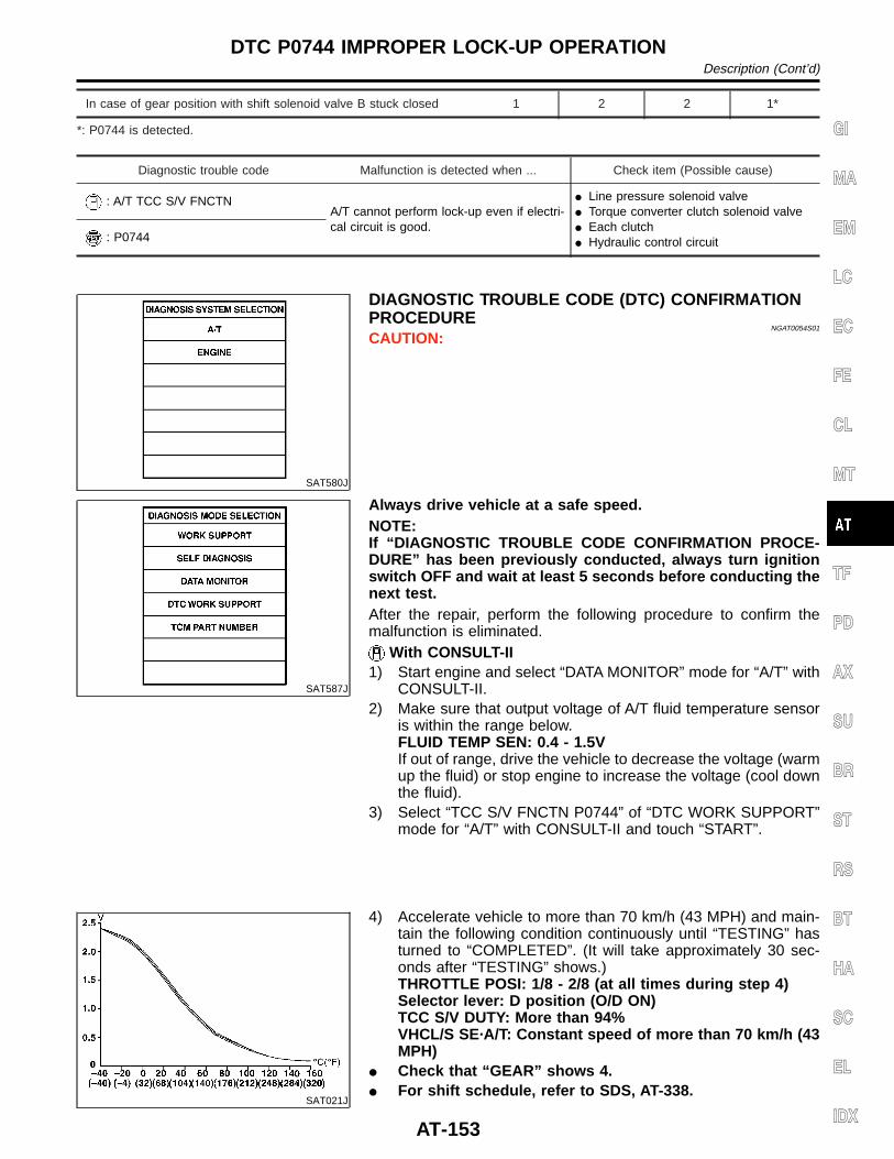
In case of gear position with shift solenoid valve B stuck closed 1 2 2 1*
*: P0744 is detected.
Diagnostic trouble code Malfunction is detected when ... Check item (Possible cause)
: A/T TCC S/V FNCTNA/T cannot perform lock-up even if electri-cal circuit is good.
I Line pressure solenoid valveI Torque converter clutch solenoid valveI Each clutchI Hydraulic control circuit: P0744
SAT580J
DIAGNOSTIC TROUBLE CODE (DTC) CONFIRMATIONPROCEDURE
NGAT0054S01
CAUTION:
SAT587J
Always drive vehicle at a safe speed.NOTE:If “DIAGNOSTIC TROUBLE CODE CONFIRMATION PROCE-DURE” has been previously conducted, always turn ignitionswitch OFF and wait at least 5 seconds before conducting thenext test.After the repair, perform the following procedure to confirm themalfunction is eliminated.
With CONSULT-II1) Start engine and select “DATA MONITOR” mode for “A/T” with
CONSULT-II.2) Make sure that output voltage of A/T fluid temperature sensor
is within the range below.FLUID TEMP SEN: 0.4 - 1.5VIf out of range, drive the vehicle to decrease the voltage (warmup the fluid) or stop engine to increase the voltage (cool downthe fluid).
3) Select “TCC S/V FNCTN P0744” of “DTC WORK SUPPORT”mode for “A/T” with CONSULT-II and touch “START”.
SAT021J
4) Accelerate vehicle to more than 70 km/h (43 MPH) and main-tain the following condition continuously until “TESTING” hasturned to “COMPLETED”. (It will take approximately 30 sec-onds after “TESTING” shows.)THROTTLE POSI: 1/8 - 2/8 (at all times during step 4)Selector lever: D position (O/D ON)TCC S/V DUTY: More than 94%VHCL/S SE·A/T: Constant speed of more than 70 km/h (43MPH)
I Check that “GEAR” shows 4.I For shift schedule, refer to SDS, AT-338.
GI
MA
EM
LC
EC
FE
CL
MT
TF
PD
AX
SU
BR
ST
RS
BT
HA
SC
EL
IDX
DTC P0744 IMPROPER LOCK-UP OPERATIONDescription (Cont’d)
AT-153
I If “TESTING” does not appear on CONSULT-II for a longtime, select “SELF-DIAG RESULTS”. In case a 1st trip DTCother than P0744 is shown, refer to applicable “TROUBLEDIAGNOSIS FOR DTC”.
5) Make sure that “OK” is displayed. (If “NG” is displayed, referto “DIAGNOSTIC PROCEDURE”.)Refer to “DIAGNOSTIC PROCEDURE”, AT-156.Refer to shift schedule, AT-338.
With GSTFollow the procedure “With CONSULT-II”.
DTC P0744 IMPROPER LOCK-UP OPERATIONDescription (Cont’d)
AT-154
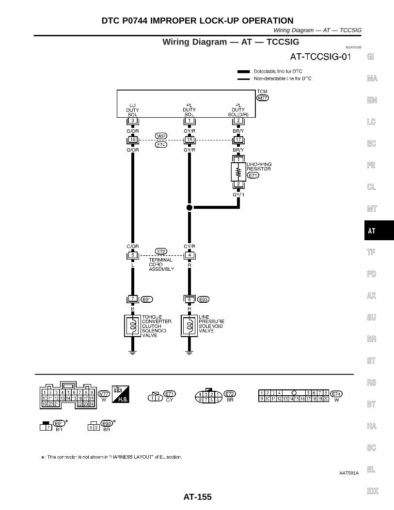
Wiring Diagram — AT — TCCSIGNGAT0195
AAT591A
GI
MA
EM
LC
EC
FE
CL
MT
TF
PD
AX
SU
BR
ST
RS
BT
HA
SC
EL
IDX
DTC P0744 IMPROPER LOCK-UP OPERATIONWiring Diagram — AT — TCCSIG
AT-155
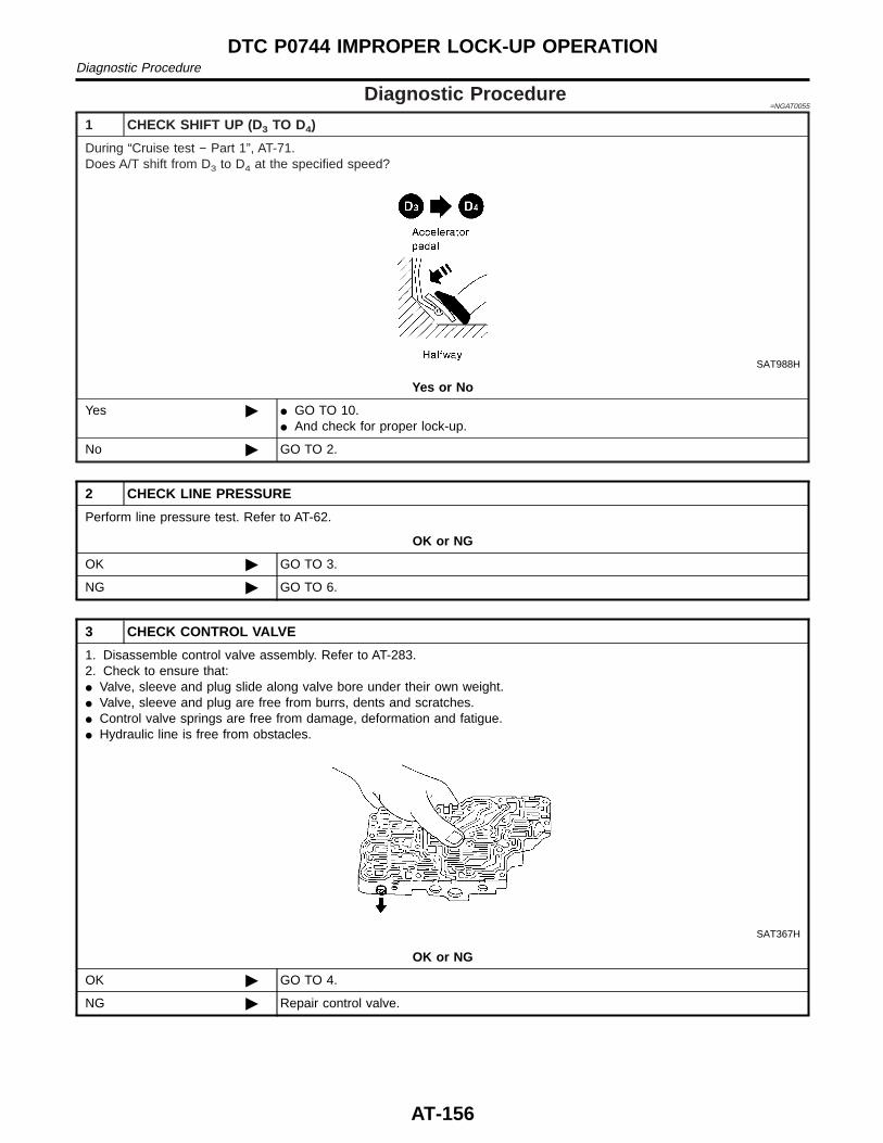
Diagnostic Procedure=NGAT0055
1 CHECK SHIFT UP (D3 TO D4)
During “Cruise test − Part 1”, AT-71.Does A/T shift from D3 to D4 at the specified speed?
SAT988H
Yes or No
Yes © I GO TO 10.I And check for proper lock-up.
No © GO TO 2.
2 CHECK LINE PRESSURE
Perform line pressure test. Refer to AT-62.
OK or NG
OK © GO TO 3.
NG © GO TO 6.
3 CHECK CONTROL VALVE
1. Disassemble control valve assembly. Refer to AT-283.2. Check to ensure that:I Valve, sleeve and plug slide along valve bore under their own weight.I Valve, sleeve and plug are free from burrs, dents and scratches.I Control valve springs are free from damage, deformation and fatigue.I Hydraulic line is free from obstacles.
SAT367H
OK or NG
OK © GO TO 4.
NG © Repair control valve.
DTC P0744 IMPROPER LOCK-UP OPERATIONDiagnostic Procedure
AT-156
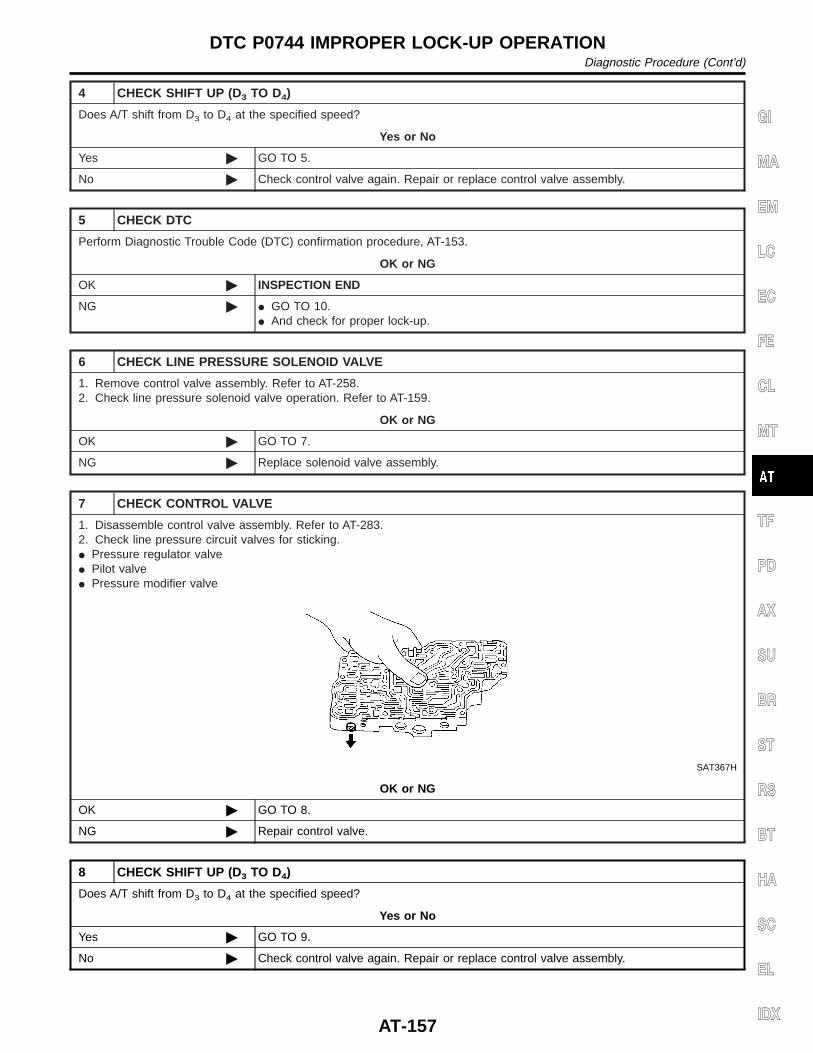
4 CHECK SHIFT UP (D3 TO D4)
Does A/T shift from D3 to D4 at the specified speed?
Yes or No
Yes © GO TO 5.
No © Check control valve again. Repair or replace control valve assembly.
5 CHECK DTC
Perform Diagnostic Trouble Code (DTC) confirmation procedure, AT-153.
OK or NG
OK © INSPECTION END
NG © I GO TO 10.I And check for proper lock-up.
6 CHECK LINE PRESSURE SOLENOID VALVE
1. Remove control valve assembly. Refer to AT-258.2. Check line pressure solenoid valve operation. Refer to AT-159.
OK or NG
OK © GO TO 7.
NG © Replace solenoid valve assembly.
7 CHECK CONTROL VALVE
1. Disassemble control valve assembly. Refer to AT-283.2. Check line pressure circuit valves for sticking.I Pressure regulator valveI Pilot valveI Pressure modifier valve
SAT367H
OK or NG
OK © GO TO 8.
NG © Repair control valve.
8 CHECK SHIFT UP (D3 TO D4)
Does A/T shift from D3 to D4 at the specified speed?
Yes or No
Yes © GO TO 9.
No © Check control valve again. Repair or replace control valve assembly.
GI
MA
EM
LC
EC
FE
CL
MT
TF
PD
AX
SU
BR
ST
RS
BT
HA
SC
EL
IDX
DTC P0744 IMPROPER LOCK-UP OPERATIONDiagnostic Procedure (Cont’d)
AT-157
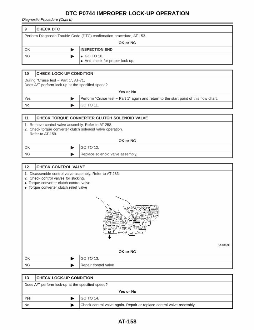
9 CHECK DTC
Perform Diagnostic Trouble Code (DTC) confirmation procedure, AT-153.
OK or NG
OK © INSPECTION END
NG © I GO TO 10.I And check for proper lock-up.
10 CHECK LOCK-UP CONDITION
During “Cruise test − Part 1”, AT-71,Does A/T perform lock-up at the specified speed?
Yes or No
Yes © Perform “Cruise test − Part 1” again and return to the start point of this flow chart.
No © GO TO 11.
11 CHECK TORQUE CONVERTER CLUTCH SOLENOID VALVE
1. Remove control valve assembly. Refer to AT-258.2. Check torque converter clutch solenoid valve operation.
Refer to AT-159.
OK or NG
OK © GO TO 12.
NG © Replace solenoid valve assembly.
12 CHECK CONTROL VALVE
1. Disassemble control valve assembly. Refer to AT-283.2. Check control valves for sticking.I Torque converter clutch control valveI Torque converter clutch relief valve
SAT367H
OK or NG
OK © GO TO 13.
NG © Repair control valve
13 CHECK LOCK-UP CONDITION
Does A/T perform lock-up at the specified speed?
Yes or No
Yes © GO TO 14.
No © Check control valve again. Repair or replace control valve assembly.
DTC P0744 IMPROPER LOCK-UP OPERATIONDiagnostic Procedure (Cont’d)
AT-158
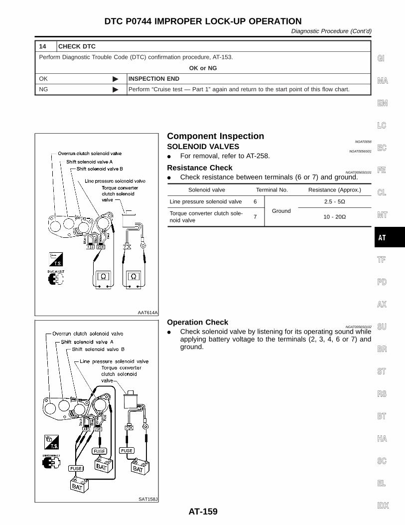
14 CHECK DTC
Perform Diagnostic Trouble Code (DTC) confirmation procedure, AT-153.
OK or NG
OK © INSPECTION END
NG © Perform “Cruise test — Part 1” again and return to the start point of this flow chart.
AAT614A
Component InspectionNGAT0056
SOLENOID VALVESNGAT0056S01
I For removal, refer to AT-258.
Resistance CheckNGAT0056S0101
I Check resistance between terminals (6 or 7) and ground.
Solenoid valve Terminal No. Resistance (Approx.)
Line pressure solenoid valve 6
Ground
2.5 - 5Ω
Torque converter clutch sole-noid valve
7 10 - 20Ω
SAT158J
Operation CheckNGAT0056S0102
I Check solenoid valve by listening for its operating sound whileapplying battery voltage to the terminals (2, 3, 4, 6 or 7) andground.
GI
MA
EM
LC
EC
FE
CL
MT
TF
PD
AX
SU
BR
ST
RS
BT
HA
SC
EL
IDX
DTC P0744 IMPROPER LOCK-UP OPERATIONDiagnostic Procedure (Cont’d)
AT-159
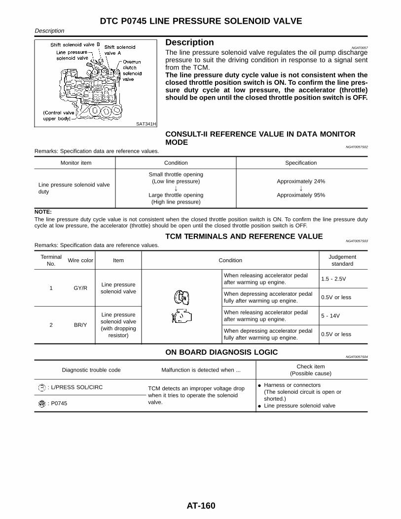
SAT341H
DescriptionNGAT0057
The line pressure solenoid valve regulates the oil pump dischargepressure to suit the driving condition in response to a signal sentfrom the TCM.The line pressure duty cycle value is not consistent when theclosed throttle position switch is ON. To confirm the line pres-sure duty cycle at low pressure, the accelerator (throttle)should be open until the closed throttle position switch is OFF.
CONSULT-II REFERENCE VALUE IN DATA MONITORMODE
NGAT0057S02
Remarks: Specification data are reference values.
Monitor item Condition Specification
Line pressure solenoid valveduty
Small throttle opening(Low line pressure)
"
Large throttle opening(High line pressure)
Approximately 24%"
Approximately 95%
NOTE:The line pressure duty cycle value is not consistent when the closed throttle position switch is ON. To confirm the line pressure dutycycle at low pressure, the accelerator (throttle) should be open until the closed throttle position switch is OFF.
TCM TERMINALS AND REFERENCE VALUENGAT0057S03
Remarks: Specification data are reference values.
TerminalNo.
Wire color Item ConditionJudgementstandard
1 GY/RLine pressuresolenoid valve
When releasing accelerator pedalafter warming up engine.
1.5 - 2.5V
When depressing accelerator pedalfully after warming up engine.
0.5V or less
2 BR/Y
Line pressuresolenoid valve(with dropping
resistor)
When releasing accelerator pedalafter warming up engine.
5 - 14V
When depressing accelerator pedalfully after warming up engine.
0.5V or less
ON BOARD DIAGNOSIS LOGICNGAT0057S04
Diagnostic trouble code Malfunction is detected when ...Check item
(Possible cause)
: L/PRESS SOL/CIRC TCM detects an improper voltage dropwhen it tries to operate the solenoidvalve.
I Harness or connectors(The solenoid circuit is open orshorted.)
I Line pressure solenoid valve: P0745
DTC P0745 LINE PRESSURE SOLENOID VALVEDescription
AT-160
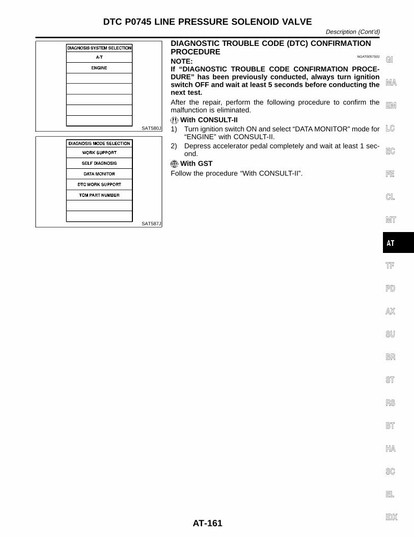
SAT580J
SAT587J
DIAGNOSTIC TROUBLE CODE (DTC) CONFIRMATIONPROCEDURE
NGAT0057S01
NOTE:If “DIAGNOSTIC TROUBLE CODE CONFIRMATION PROCE-DURE” has been previously conducted, always turn ignitionswitch OFF and wait at least 5 seconds before conducting thenext test.After the repair, perform the following procedure to confirm themalfunction is eliminated.
With CONSULT-II1) Turn ignition switch ON and select “DATA MONITOR” mode for
“ENGINE” with CONSULT-II.2) Depress accelerator pedal completely and wait at least 1 sec-
ond.With GST
Follow the procedure “With CONSULT-II”.
GI
MA
EM
LC
EC
FE
CL
MT
TF
PD
AX
SU
BR
ST
RS
BT
HA
SC
EL
IDX
DTC P0745 LINE PRESSURE SOLENOID VALVEDescription (Cont’d)
AT-161
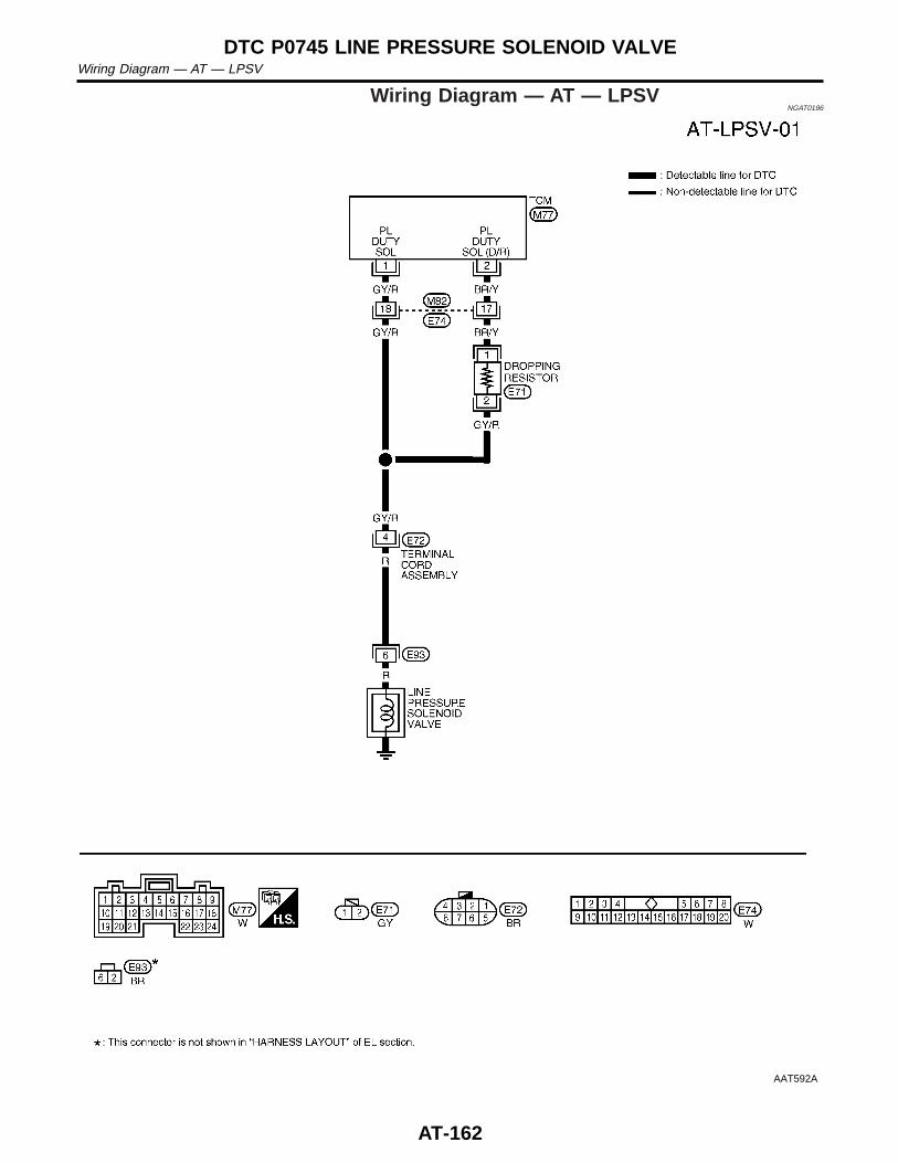
Wiring Diagram — AT — LPSVNGAT0196
AAT592A
DTC P0745 LINE PRESSURE SOLENOID VALVEWiring Diagram — AT — LPSV
AT-162
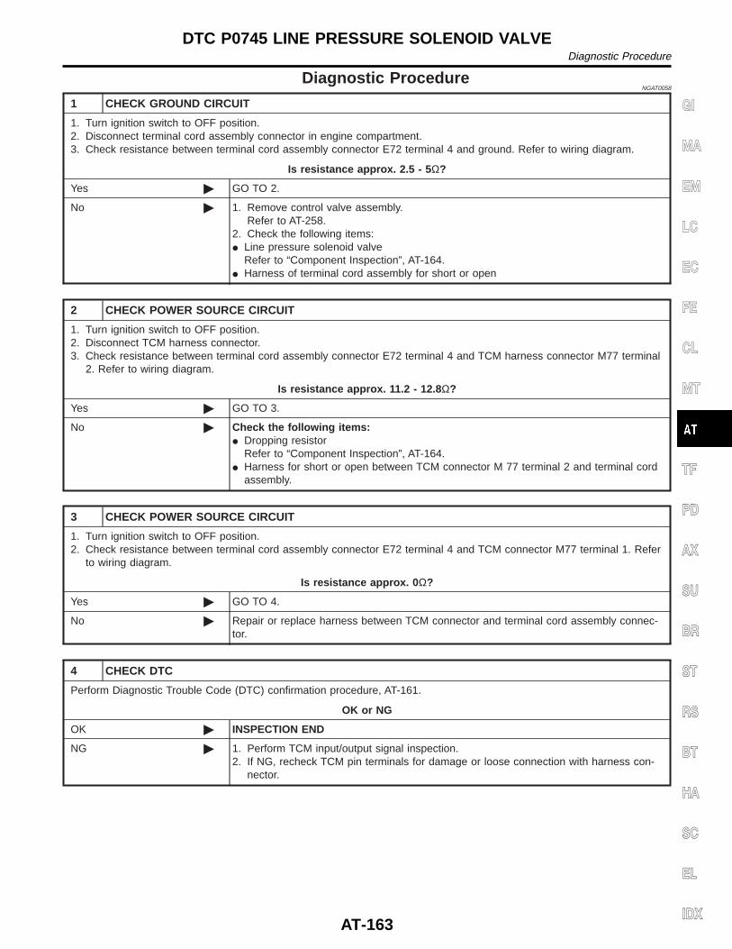
Diagnostic ProcedureNGAT0058
1 CHECK GROUND CIRCUIT
1. Turn ignition switch to OFF position.2. Disconnect terminal cord assembly connector in engine compartment.3. Check resistance between terminal cord assembly connector E72 terminal 4 and ground. Refer to wiring diagram.
Is resistance approx. 2.5 - 5 Ω?
Yes © GO TO 2.
No © 1. Remove control valve assembly.Refer to AT-258.
2. Check the following items:I Line pressure solenoid valve
Refer to “Component Inspection”, AT-164.I Harness of terminal cord assembly for short or open
2 CHECK POWER SOURCE CIRCUIT
1. Turn ignition switch to OFF position.2. Disconnect TCM harness connector.3. Check resistance between terminal cord assembly connector E72 terminal 4 and TCM harness connector M77 terminal
2. Refer to wiring diagram.
Is resistance approx. 11.2 - 12.8 Ω?
Yes © GO TO 3.
No © Check the following items:I Dropping resistor
Refer to “Component Inspection”, AT-164.I Harness for short or open between TCM connector M 77 terminal 2 and terminal cord
assembly.
3 CHECK POWER SOURCE CIRCUIT
1. Turn ignition switch to OFF position.2. Check resistance between terminal cord assembly connector E72 terminal 4 and TCM connector M77 terminal 1. Refer
to wiring diagram.
Is resistance approx. 0 Ω?
Yes © GO TO 4.
No © Repair or replace harness between TCM connector and terminal cord assembly connec-tor.
4 CHECK DTC
Perform Diagnostic Trouble Code (DTC) confirmation procedure, AT-161.
OK or NG
OK © INSPECTION END
NG © 1. Perform TCM input/output signal inspection.2. If NG, recheck TCM pin terminals for damage or loose connection with harness con-
nector.
GI
MA
EM
LC
EC
FE
CL
MT
TF
PD
AX
SU
BR
ST
RS
BT
HA
SC
EL
IDX
DTC P0745 LINE PRESSURE SOLENOID VALVEDiagnostic Procedure
AT-163
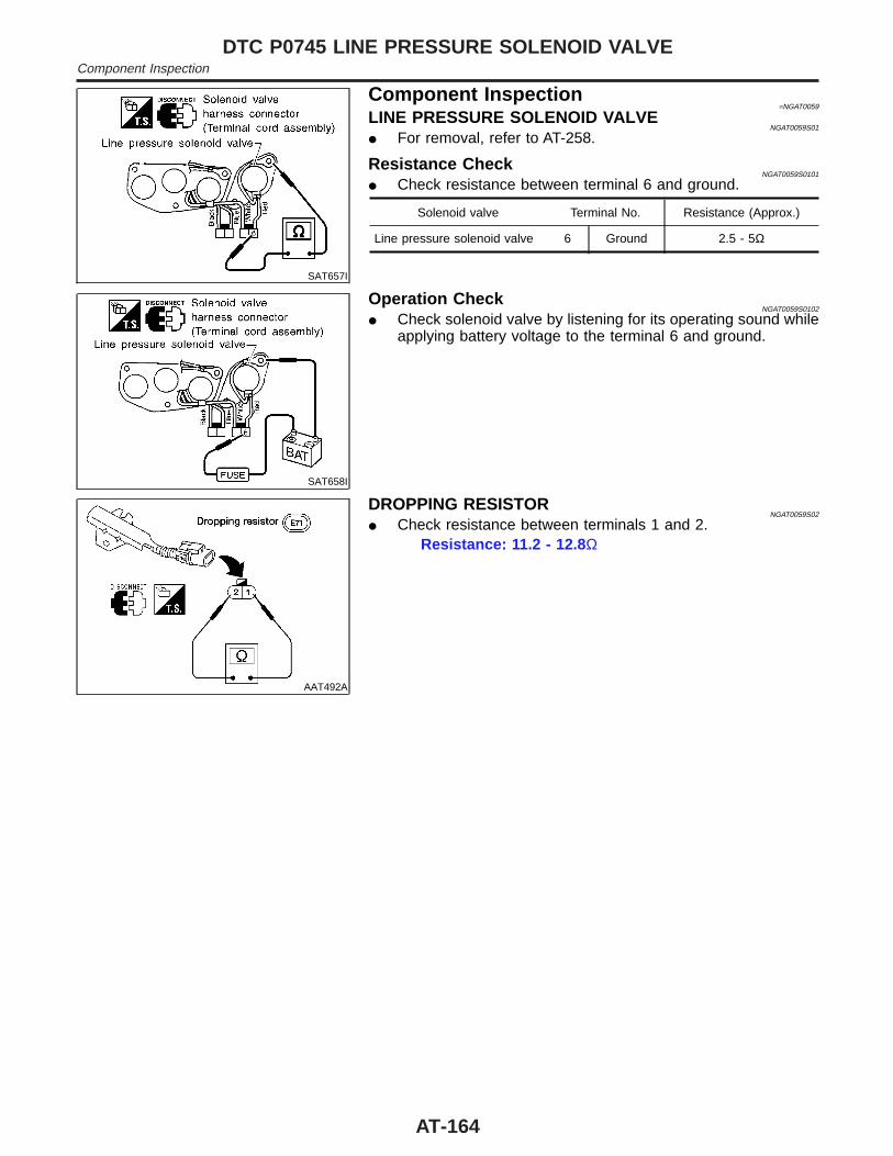
SAT657I
Component Inspection=NGAT0059
LINE PRESSURE SOLENOID VALVENGAT0059S01
I For removal, refer to AT-258.
Resistance CheckNGAT0059S0101
I Check resistance between terminal 6 and ground.
Solenoid valve Terminal No. Resistance (Approx.)
Line pressure solenoid valve 6 Ground 2.5 - 5Ω
SAT658I
Operation CheckNGAT0059S0102
I Check solenoid valve by listening for its operating sound whileapplying battery voltage to the terminal 6 and ground.
AAT492A
DROPPING RESISTORNGAT0059S02
I Check resistance between terminals 1 and 2.Resistance: 11.2 - 12.8 Ω
DTC P0745 LINE PRESSURE SOLENOID VALVEComponent Inspection
AT-164
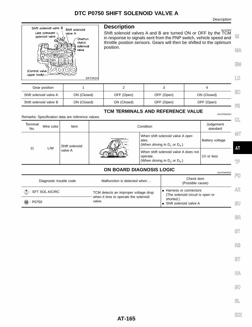
SAT341H
DescriptionNGAT0060
Shift solenoid valves A and B are turned ON or OFF by the TCMin response to signals sent from the PNP switch, vehicle speed andthrottle position sensors. Gears will then be shifted to the optimumposition.
Gear position 1 2 3 4
Shift solenoid valve A ON (Closed) OFF (Open) OFF (Open) ON (Closed)
Shift solenoid valve B ON (Closed) ON (Closed) OFF (Open) OFF (Open)
TCM TERMINALS AND REFERENCE VALUENGAT0060S02
Remarks: Specification data are reference values.
TerminalNo.
Wire color Item ConditionJudgementstandard
11 L/WShift solenoidvalve A
When shift solenoid valve A oper-ates.(When driving in D1 or D4.)
Battery voltage
When shift solenoid valve A does notoperate.(When driving in D2 or D3.)
1V or less
ON BOARD DIAGNOSIS LOGICNGAT0060S03
Diagnostic trouble code Malfunction is detected when ...Check item
(Possible cause)
: SFT SOL A/CIRC TCM detects an improper voltage dropwhen it tires to operate the solenoidvalve.
I Harness or connectors(The solenoid circuit is open orshorted.)
I Shift solenoid valve A: P0750
GI
MA
EM
LC
EC
FE
CL
MT
TF
PD
AX
SU
BR
ST
RS
BT
HA
SC
EL
IDX
DTC P0750 SHIFT SOLENOID VALVE ADescription
AT-165
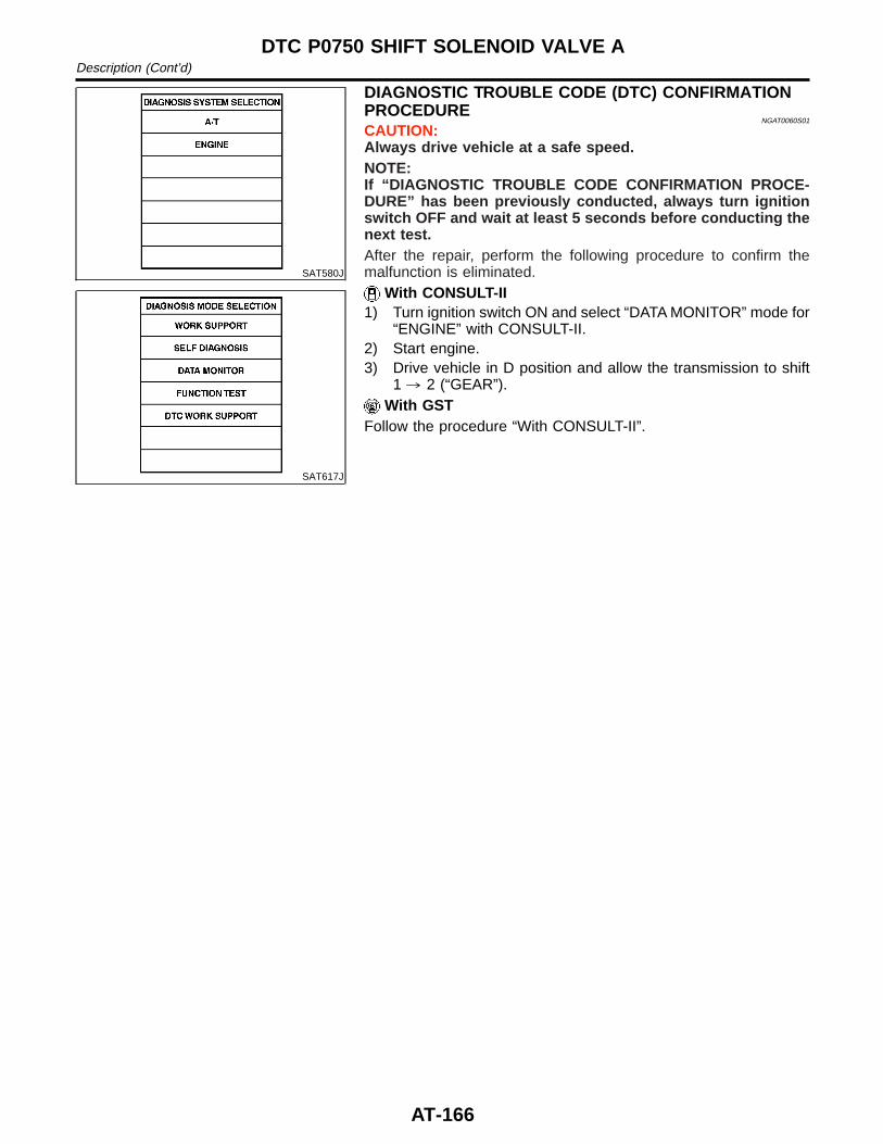
SAT580J
SAT617J
DIAGNOSTIC TROUBLE CODE (DTC) CONFIRMATIONPROCEDURE
NGAT0060S01
CAUTION:Always drive vehicle at a safe speed.NOTE:If “DIAGNOSTIC TROUBLE CODE CONFIRMATION PROCE-DURE” has been previously conducted, always turn ignitionswitch OFF and wait at least 5 seconds before conducting thenext test.After the repair, perform the following procedure to confirm themalfunction is eliminated.
With CONSULT-II1) Turn ignition switch ON and select “DATA MONITOR” mode for
“ENGINE” with CONSULT-II.2) Start engine.3) Drive vehicle in D position and allow the transmission to shift
1 , 2 (“GEAR”).With GST
Follow the procedure “With CONSULT-II”.
DTC P0750 SHIFT SOLENOID VALVE ADescription (Cont’d)
AT-166
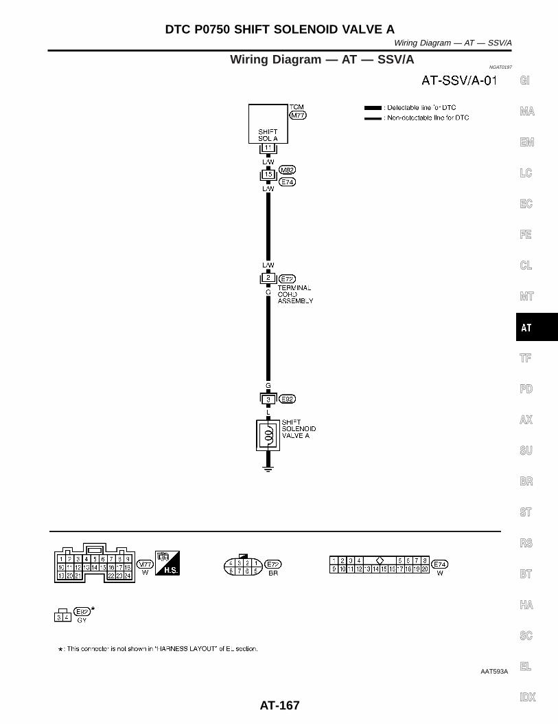
Wiring Diagram — AT — SSV/ANGAT0197
AAT593A
GI
MA
EM
LC
EC
FE
CL
MT
TF
PD
AX
SU
BR
ST
RS
BT
HA
SC
EL
IDX
DTC P0750 SHIFT SOLENOID VALVE AWiring Diagram — AT — SSV/A
AT-167
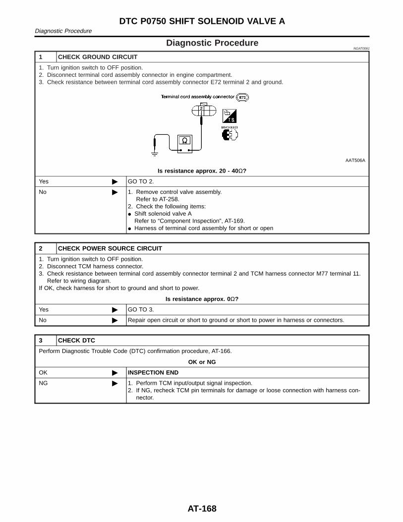
Diagnostic ProcedureNGAT0061
1 CHECK GROUND CIRCUIT
1. Turn ignition switch to OFF position.2. Disconnect terminal cord assembly connector in engine compartment.3. Check resistance between terminal cord assembly connector E72 terminal 2 and ground.
AAT506A
Is resistance approx. 20 - 40 Ω?
Yes © GO TO 2.
No © 1. Remove control valve assembly.Refer to AT-258.
2. Check the following items:I Shift solenoid valve A
Refer to “Component Inspection”, AT-169.I Harness of terminal cord assembly for short or open
2 CHECK POWER SOURCE CIRCUIT
1. Turn ignition switch to OFF position.2. Disconnect TCM harness connector.3. Check resistance between terminal cord assembly connector terminal 2 and TCM harness connector M77 terminal 11.
Refer to wiring diagram.If OK, check harness for short to ground and short to power.
Is resistance approx. 0 Ω?
Yes © GO TO 3.
No © Repair open circuit or short to ground or short to power in harness or connectors.
3 CHECK DTC
Perform Diagnostic Trouble Code (DTC) confirmation procedure, AT-166.
OK or NG
OK © INSPECTION END
NG © 1. Perform TCM input/output signal inspection.2. If NG, recheck TCM pin terminals for damage or loose connection with harness con-
nector.
DTC P0750 SHIFT SOLENOID VALVE ADiagnostic Procedure
AT-168
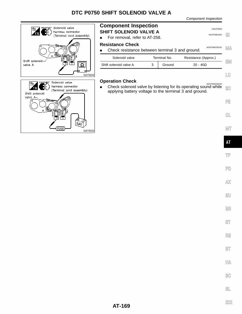
SAT654I
Component Inspection=NGAT0062
SHIFT SOLENOID VALVE ANGAT0062S01
I For removal, refer to AT-258.
Resistance CheckNGAT0062S0101
I Check resistance between terminal 3 and ground.
Solenoid valve Terminal No. Resistance (Approx.)
Shift solenoid valve A 3 Ground 20 - 40Ω
SAT653I
Operation CheckNGAT0062S0102
I Check solenoid valve by listening for its operating sound whileapplying battery voltage to the terminal 3 and ground.
GI
MA
EM
LC
EC
FE
CL
MT
TF
PD
AX
SU
BR
ST
RS
BT
HA
SC
EL
IDX
DTC P0750 SHIFT SOLENOID VALVE AComponent Inspection
AT-169
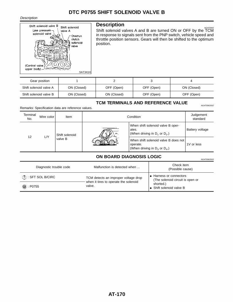
SAT341H
DescriptionNGAT0063
Shift solenoid valves A and B are turned ON or OFF by the TCMin response to signals sent from the PNP switch, vehicle speed andthrottle position sensors. Gears will then be shifted to the optimumposition.
Gear position 1 2 3 4
Shift solenoid valve A ON (Closed) OFF (Open) OFF (Open) ON (Closed)
Shift solenoid valve B ON (Closed) ON (Closed) OFF (Open) OFF (Open)
TCM TERMINALS AND REFERENCE VALUENGAT0063S02
Remarks: Specification data are reference values.
TerminalNo.
Wire color Item ConditionJudgementstandard
12 L/YShift solenoidvalve B
When shift solenoid valve B oper-ates.(When driving in D1 or D2.)
Battery voltage
When shift solenoid valve B does notoperate.(When driving in D3 or D4.)
1V or less
ON BOARD DIAGNOSIS LOGICNGAT0063S03
Diagnostic trouble code Malfunction is detected when ...Check item
(Possible cause)
: SFT SOL B/CIRC TCM detects an improper voltage dropwhen it tires to operate the solenoidvalve.
I Harness or connectors(The solenoid circuit is open orshorted.)
I Shift solenoid valve B: P0755
DTC P0755 SHIFT SOLENOID VALVE BDescription
AT-170
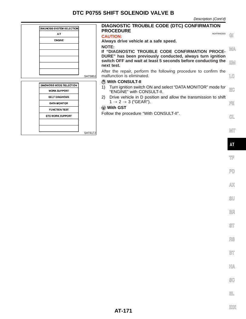
SAT580J
SAT617J
DIAGNOSTIC TROUBLE CODE (DTC) CONFIRMATIONPROCEDURE
NGAT0063S01
CAUTION:Always drive vehicle at a safe speed.NOTE:If “DIAGNOSTIC TROUBLE CODE CONFIRMATION PROCE-DURE” has been previously conducted, always turn ignitionswitch OFF and wait at least 5 seconds before conducting thenext test.After the repair, perform the following procedure to confirm themalfunction is eliminated.
With CONSULT-II1) Turn ignition switch ON and select “DATA MONITOR” mode for
“ENGINE” with CONSULT-II.2) Drive vehicle in D position and allow the transmission to shift
1 , 2 , 3 (“GEAR”).With GST
Follow the procedure “With CONSULT-II”.
GI
MA
EM
LC
EC
FE
CL
MT
TF
PD
AX
SU
BR
ST
RS
BT
HA
SC
EL
IDX
DTC P0755 SHIFT SOLENOID VALVE BDescription (Cont’d)
AT-171
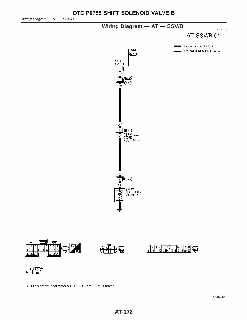
Wiring Diagram — AT — SSV/BNGAT0198
AAT594A
DTC P0755 SHIFT SOLENOID VALVE BWiring Diagram — AT — SSV/B
AT-172
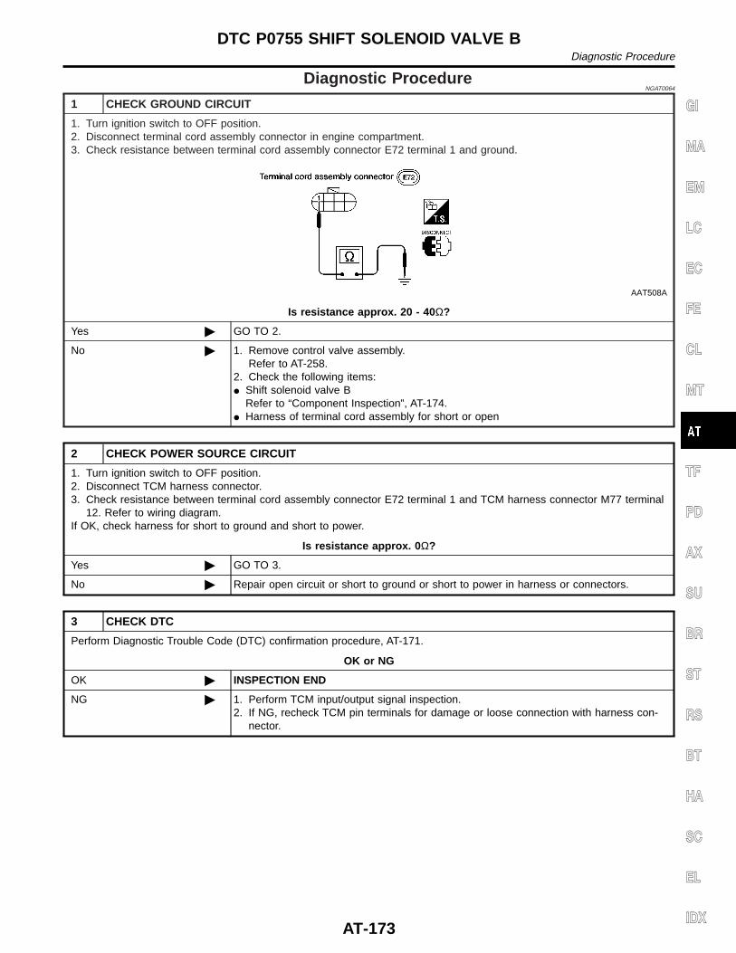
Diagnostic ProcedureNGAT0064
1 CHECK GROUND CIRCUIT
1. Turn ignition switch to OFF position.2. Disconnect terminal cord assembly connector in engine compartment.3. Check resistance between terminal cord assembly connector E72 terminal 1 and ground.
AAT508A
Is resistance approx. 20 - 40 Ω?
Yes © GO TO 2.
No © 1. Remove control valve assembly.Refer to AT-258.
2. Check the following items:I Shift solenoid valve B
Refer to “Component Inspection”, AT-174.I Harness of terminal cord assembly for short or open
2 CHECK POWER SOURCE CIRCUIT
1. Turn ignition switch to OFF position.2. Disconnect TCM harness connector.3. Check resistance between terminal cord assembly connector E72 terminal 1 and TCM harness connector M77 terminal
12. Refer to wiring diagram.If OK, check harness for short to ground and short to power.
Is resistance approx. 0 Ω?
Yes © GO TO 3.
No © Repair open circuit or short to ground or short to power in harness or connectors.
3 CHECK DTC
Perform Diagnostic Trouble Code (DTC) confirmation procedure, AT-171.
OK or NG
OK © INSPECTION END
NG © 1. Perform TCM input/output signal inspection.2. If NG, recheck TCM pin terminals for damage or loose connection with harness con-
nector.
GI
MA
EM
LC
EC
FE
CL
MT
TF
PD
AX
SU
BR
ST
RS
BT
HA
SC
EL
IDX
DTC P0755 SHIFT SOLENOID VALVE BDiagnostic Procedure
AT-173
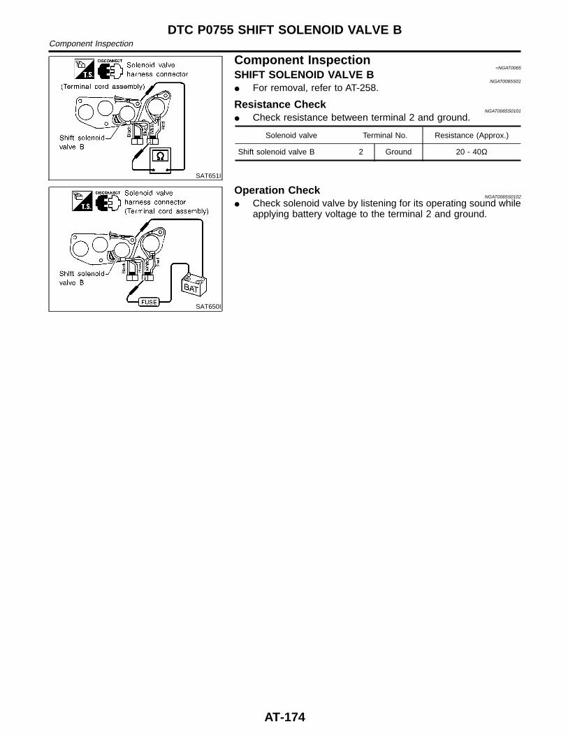
SAT651I
Component Inspection=NGAT0065
SHIFT SOLENOID VALVE BNGAT0065S01
I For removal, refer to AT-258.
Resistance CheckNGAT0065S0101
I Check resistance between terminal 2 and ground.
Solenoid valve Terminal No. Resistance (Approx.)
Shift solenoid valve B 2 Ground 20 - 40Ω
SAT650I
Operation CheckNGAT0065S0102
I Check solenoid valve by listening for its operating sound whileapplying battery voltage to the terminal 2 and ground.
DTC P0755 SHIFT SOLENOID VALVE BComponent Inspection
AT-174
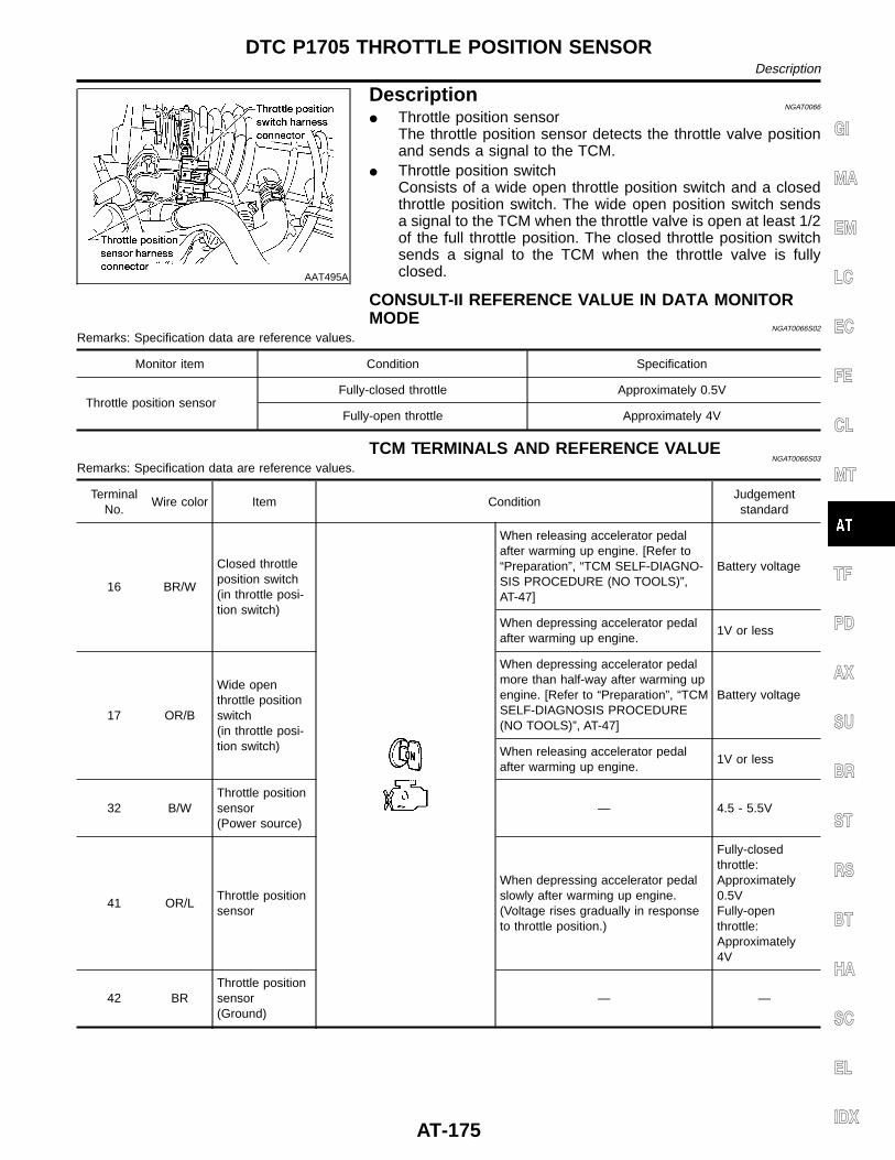
AAT495A
DescriptionNGAT0066
I Throttle position sensorThe throttle position sensor detects the throttle valve positionand sends a signal to the TCM.
I Throttle position switchConsists of a wide open throttle position switch and a closedthrottle position switch. The wide open position switch sendsa signal to the TCM when the throttle valve is open at least 1/2of the full throttle position. The closed throttle position switchsends a signal to the TCM when the throttle valve is fullyclosed.
CONSULT-II REFERENCE VALUE IN DATA MONITORMODE
NGAT0066S02
Remarks: Specification data are reference values.
Monitor item Condition Specification
Throttle position sensorFully-closed throttle Approximately 0.5V
Fully-open throttle Approximately 4V
TCM TERMINALS AND REFERENCE VALUENGAT0066S03
Remarks: Specification data are reference values.
TerminalNo.
Wire color Item ConditionJudgementstandard
16 BR/W
Closed throttleposition switch(in throttle posi-tion switch)
When releasing accelerator pedalafter warming up engine. [Refer to“Preparation”, “TCM SELF-DIAGNO-SIS PROCEDURE (NO TOOLS)”,AT-47]
Battery voltage
When depressing accelerator pedalafter warming up engine.
1V or less
17 OR/B
Wide openthrottle positionswitch(in throttle posi-tion switch)
When depressing accelerator pedalmore than half-way after warming upengine. [Refer to “Preparation”, “TCMSELF-DIAGNOSIS PROCEDURE(NO TOOLS)”, AT-47]
Battery voltage
When releasing accelerator pedalafter warming up engine.
1V or less
32 B/WThrottle positionsensor(Power source)
— 4.5 - 5.5V
41 OR/LThrottle positionsensor
When depressing accelerator pedalslowly after warming up engine.(Voltage rises gradually in responseto throttle position.)
Fully-closedthrottle:Approximately0.5VFully-openthrottle:Approximately4V
42 BRThrottle positionsensor(Ground)
— —
GI
MA
EM
LC
EC
FE
CL
MT
TF
PD
AX
SU
BR
ST
RS
BT
HA
SC
EL
IDX
DTC P1705 THROTTLE POSITION SENSORDescription
AT-175
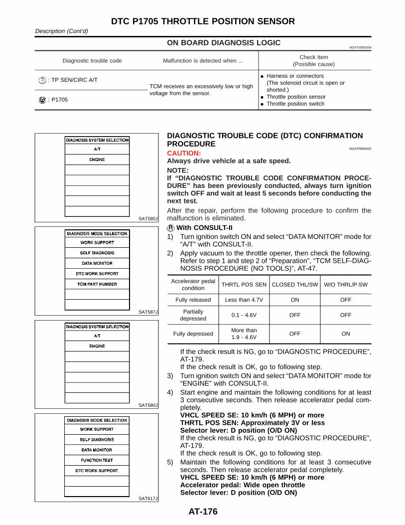
ON BOARD DIAGNOSIS LOGICNGAT0066S04
Diagnostic trouble code Malfunction is detected when ...Check item
(Possible cause)
: TP SEN/CIRC A/TTCM receives an excessively low or highvoltage from the sensor.
I Harness or connectors(The solenoid circuit is open orshorted.)
I Throttle position sensorI Throttle position switch
: P1705
SAT580J
SAT587J
SAT580J
SAT617J
DIAGNOSTIC TROUBLE CODE (DTC) CONFIRMATIONPROCEDURE
NGAT0066S01
CAUTION:Always drive vehicle at a safe speed.NOTE:If “DIAGNOSTIC TROUBLE CODE CONFIRMATION PROCE-DURE” has been previously conducted, always turn ignitionswitch OFF and wait at least 5 seconds before conducting thenext test.After the repair, perform the following procedure to confirm themalfunction is eliminated.
With CONSULT-II1) Turn ignition switch ON and select “DATA MONITOR” mode for
“A/T” with CONSULT-II.2) Apply vacuum to the throttle opener, then check the following.
Refer to step 1 and step 2 of “Preparation”, “TCM SELF-DIAG-NOSIS PROCEDURE (NO TOOLS)”, AT-47.
Accelerator pedalcondition
THRTL POS SEN CLOSED THL/SW W/O THRL/P·SW
Fully released Less than 4.7V ON OFF
Partiallydepressed
0.1 - 4.6V OFF OFF
Fully depressedMore than1.9 - 4.6V
OFF ON
If the check result is NG, go to “DIAGNOSTIC PROCEDURE”,AT-179.If the check result is OK, go to following step.
3) Turn ignition switch ON and select “DATA MONITOR” mode for“ENGINE” with CONSULT-II.
4) Start engine and maintain the following conditions for at least3 consecutive seconds. Then release accelerator pedal com-pletely.VHCL SPEED SE: 10 km/h (6 MPH) or moreTHRTL POS SEN: Approximately 3V or lessSelector lever: D position (O/D ON)If the check result is NG, go to “DIAGNOSTIC PROCEDURE”,AT-179.If the check result is OK, go to following step.
5) Maintain the following conditions for at least 3 consecutiveseconds. Then release accelerator pedal completely.VHCL SPEED SE: 10 km/h (6 MPH) or moreAccelerator pedal: Wide open throttleSelector lever: D position (O/D ON)
DTC P1705 THROTTLE POSITION SENSORDescription (Cont’d)
AT-176
With GSTFollow the procedure “With CONSULT-II”.
GI
MA
EM
LC
EC
FE
CL
MT
TF
PD
AX
SU
BR
ST
RS
BT
HA
SC
EL
IDX
DTC P1705 THROTTLE POSITION SENSORDescription (Cont’d)
AT-177
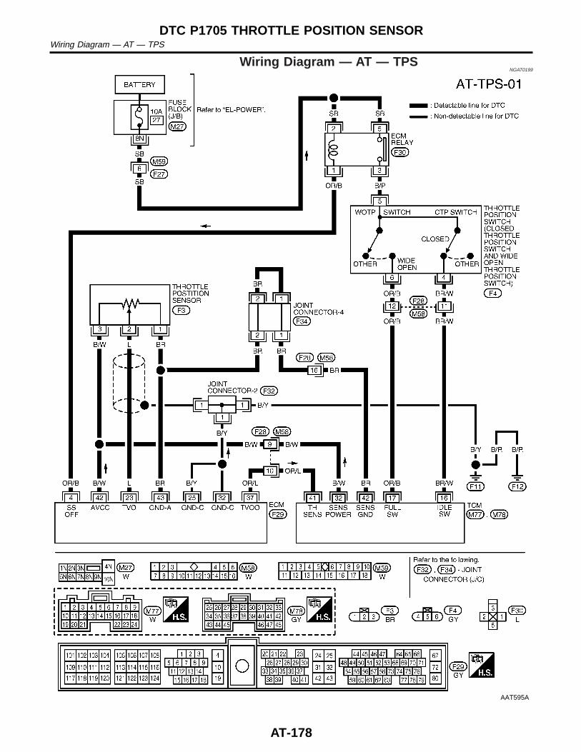
Wiring Diagram — AT — TPSNGAT0199
AAT595A
DTC P1705 THROTTLE POSITION SENSORWiring Diagram — AT — TPS
AT-178
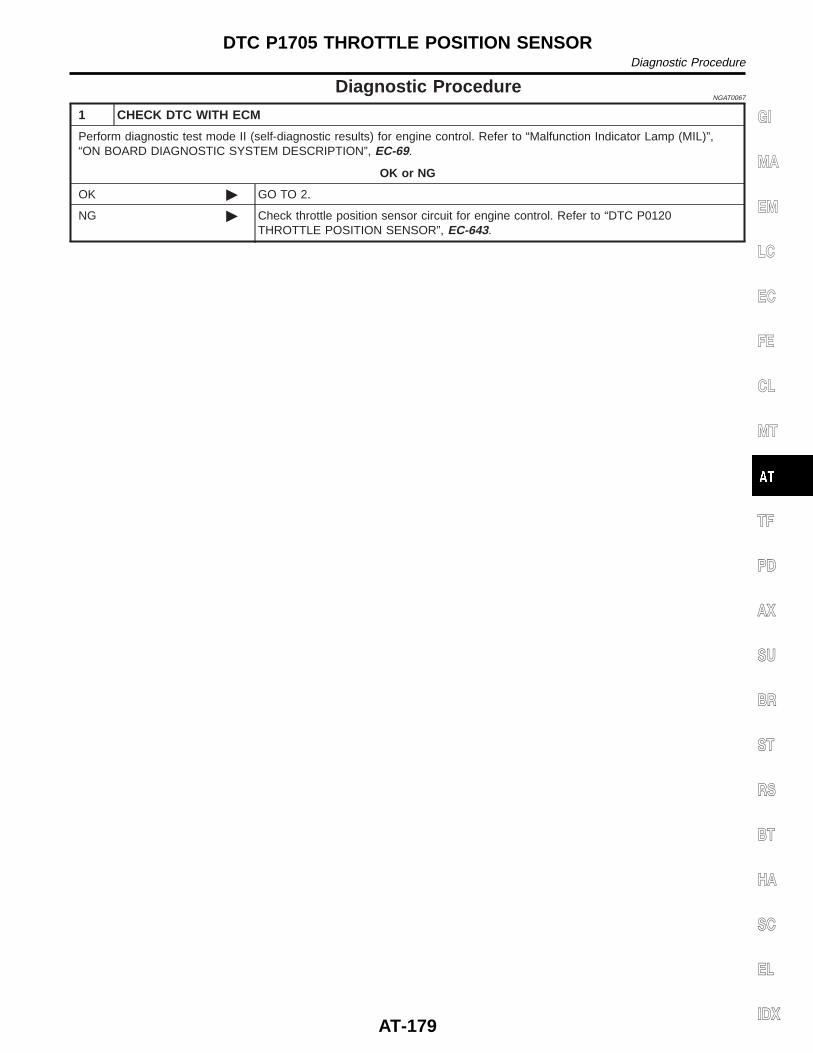
Diagnostic ProcedureNGAT0067
1 CHECK DTC WITH ECM
Perform diagnostic test mode II (self-diagnostic results) for engine control. Refer to “Malfunction Indicator Lamp (MIL)”,“ON BOARD DIAGNOSTIC SYSTEM DESCRIPTION”, EC-69.
OK or NG
OK © GO TO 2.
NG © Check throttle position sensor circuit for engine control. Refer to “DTC P0120THROTTLE POSITION SENSOR”, EC-643.
GI
MA
EM
LC
EC
FE
CL
MT
TF
PD
AX
SU
BR
ST
RS
BT
HA
SC
EL
IDX
DTC P1705 THROTTLE POSITION SENSORDiagnostic Procedure
AT-179
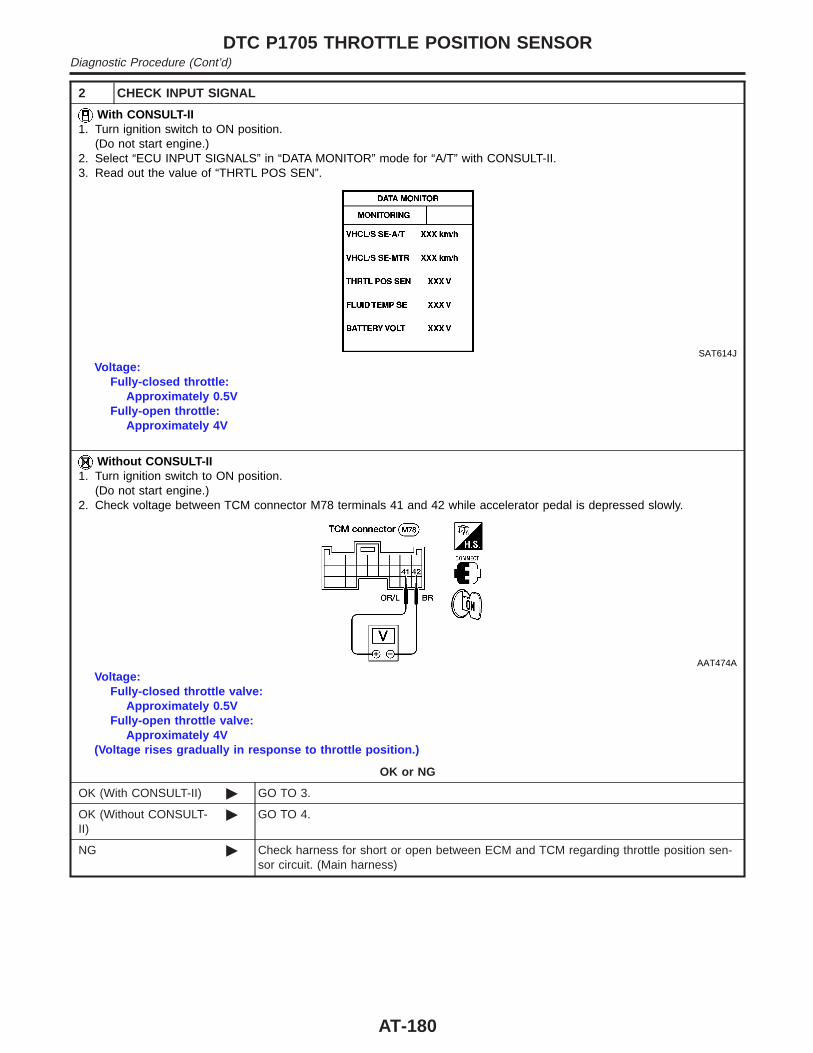
2 CHECK INPUT SIGNAL
With CONSULT-II1. Turn ignition switch to ON position.
(Do not start engine.)2. Select “ECU INPUT SIGNALS” in “DATA MONITOR” mode for “A/T” with CONSULT-II.3. Read out the value of “THRTL POS SEN”.
SAT614J
Voltage:Fully-closed throttle:
Approximately 0.5VFully-open throttle:
Approximately 4V
Without CONSULT-II1. Turn ignition switch to ON position.
(Do not start engine.)2. Check voltage between TCM connector M78 terminals 41 and 42 while accelerator pedal is depressed slowly.
AAT474A
Voltage:Fully-closed throttle valve:
Approximately 0.5VFully-open throttle valve:
Approximately 4V(Voltage rises gradually in response to throttle position.)
OK or NG
OK (With CONSULT-II) © GO TO 3.
OK (Without CONSULT-II)
© GO TO 4.
NG © Check harness for short or open between ECM and TCM regarding throttle position sen-sor circuit. (Main harness)
DTC P1705 THROTTLE POSITION SENSORDiagnostic Procedure (Cont’d)
AT-180
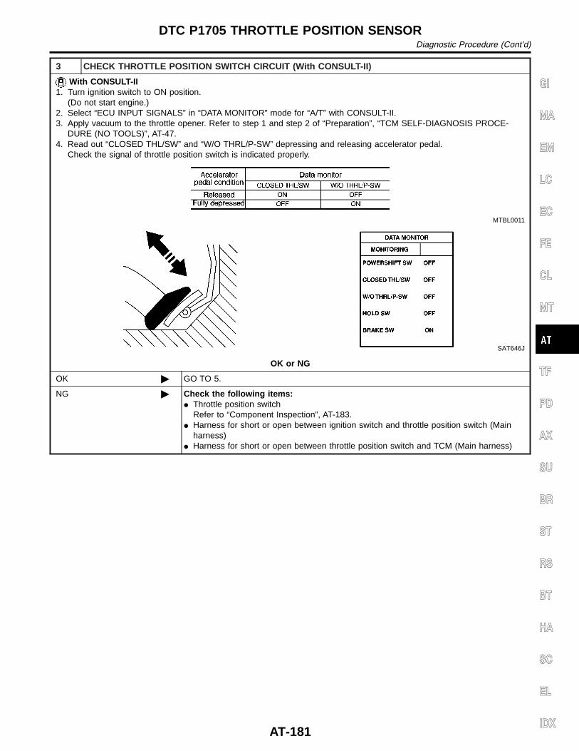
3 CHECK THROTTLE POSITION SWITCH CIRCUIT (With CONSULT-II)
With CONSULT-II1. Turn ignition switch to ON position.
(Do not start engine.)2. Select “ECU INPUT SIGNALS” in “DATA MONITOR” mode for “A/T” with CONSULT-II.3. Apply vacuum to the throttle opener. Refer to step 1 and step 2 of “Preparation”, “TCM SELF-DIAGNOSIS PROCE-
DURE (NO TOOLS)”, AT-47.4. Read out “CLOSED THL/SW” and “W/O THRL/P-SW” depressing and releasing accelerator pedal.
Check the signal of throttle position switch is indicated properly.
MTBL0011
SAT646J
OK or NG
OK © GO TO 5.
NG © Check the following items:I Throttle position switch
Refer to “Component Inspection”, AT-183.I Harness for short or open between ignition switch and throttle position switch (Main
harness)I Harness for short or open between throttle position switch and TCM (Main harness)
GI
MA
EM
LC
EC
FE
CL
MT
TF
PD
AX
SU
BR
ST
RS
BT
HA
SC
EL
IDX
DTC P1705 THROTTLE POSITION SENSORDiagnostic Procedure (Cont’d)
AT-181
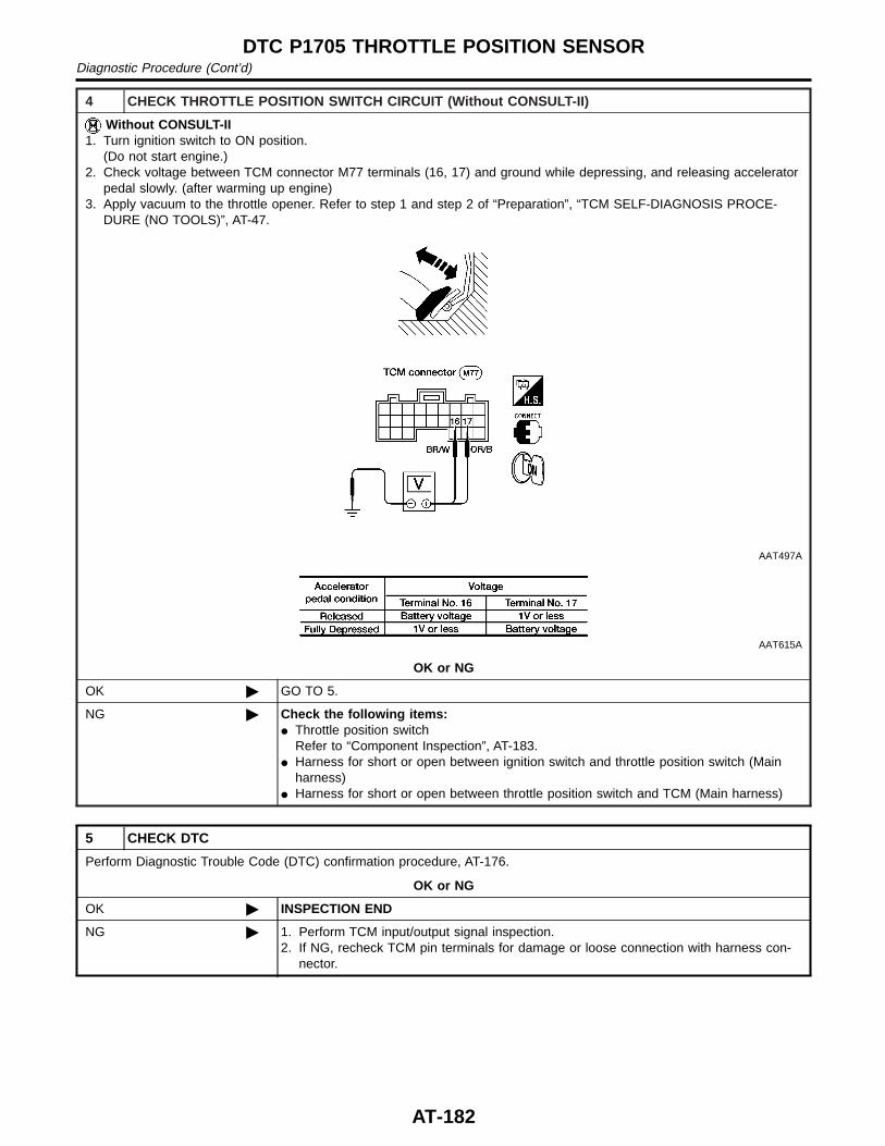
4 CHECK THROTTLE POSITION SWITCH CIRCUIT (Without CONSULT-II)
Without CONSULT-II1. Turn ignition switch to ON position.
(Do not start engine.)2. Check voltage between TCM connector M77 terminals (16, 17) and ground while depressing, and releasing accelerator
pedal slowly. (after warming up engine)3. Apply vacuum to the throttle opener. Refer to step 1 and step 2 of “Preparation”, “TCM SELF-DIAGNOSIS PROCE-
DURE (NO TOOLS)”, AT-47.
AAT497A
AAT615A
OK or NG
OK © GO TO 5.
NG © Check the following items:I Throttle position switch
Refer to “Component Inspection”, AT-183.I Harness for short or open between ignition switch and throttle position switch (Main
harness)I Harness for short or open between throttle position switch and TCM (Main harness)
5 CHECK DTC
Perform Diagnostic Trouble Code (DTC) confirmation procedure, AT-176.
OK or NG
OK © INSPECTION END
NG © 1. Perform TCM input/output signal inspection.2. If NG, recheck TCM pin terminals for damage or loose connection with harness con-
nector.
DTC P1705 THROTTLE POSITION SENSORDiagnostic Procedure (Cont’d)
AT-182
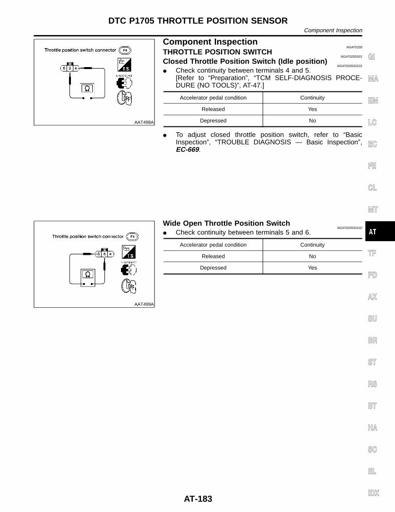
AAT498A
Component InspectionNGAT0205
THROTTLE POSITION SWITCHNGAT0205S01
Closed Throttle Position Switch (Idle position)NGAT0205S0101
I Check continuity between terminals 4 and 5.[Refer to “Preparation”, “TCM SELF-DIAGNOSIS PROCE-DURE (NO TOOLS)”, AT-47.]
Accelerator pedal condition Continuity
Released Yes
Depressed No
I To adjust closed throttle position switch, refer to “BasicInspection”, “TROUBLE DIAGNOSIS — Basic Inspection”,EC-669.
AAT499A
Wide Open Throttle Position SwitchNGAT0205S0102
I Check continuity between terminals 5 and 6.
Accelerator pedal condition Continuity
Released No
Depressed Yes
GI
MA
EM
LC
EC
FE
CL
MT
TF
PD
AX
SU
BR
ST
RS
BT
HA
SC
EL
IDX
DTC P1705 THROTTLE POSITION SENSORComponent Inspection
AT-183
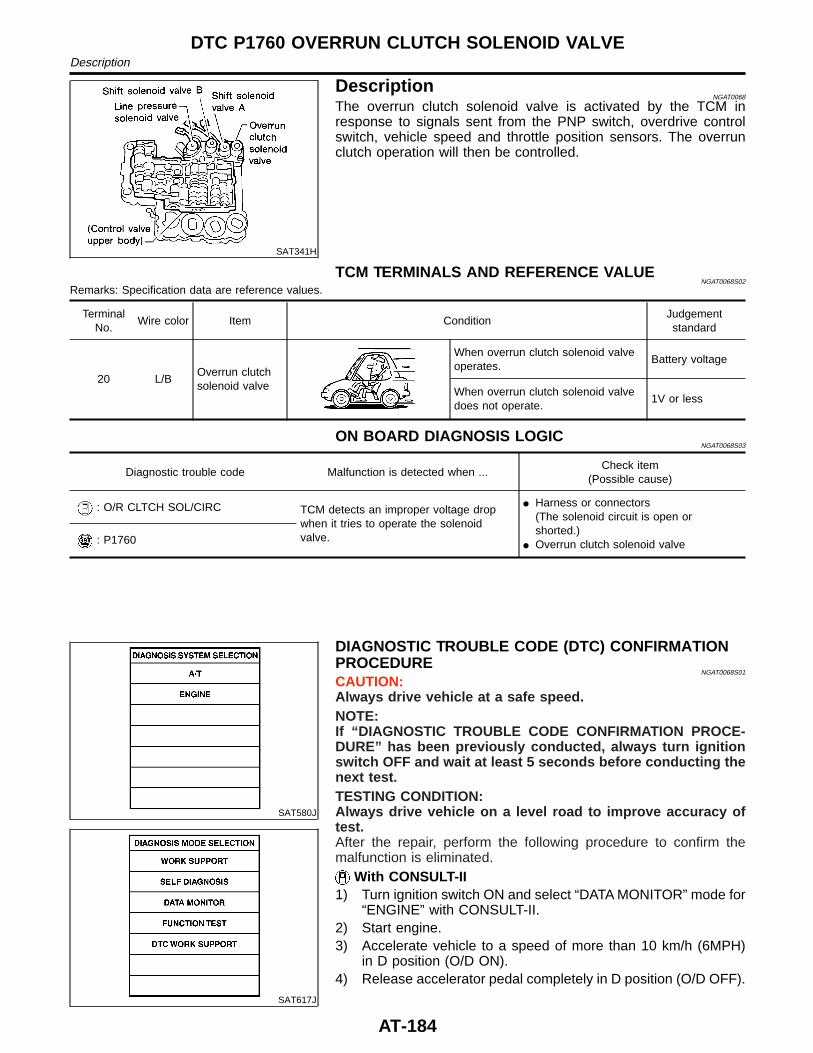
SAT341H
DescriptionNGAT0068
The overrun clutch solenoid valve is activated by the TCM inresponse to signals sent from the PNP switch, overdrive controlswitch, vehicle speed and throttle position sensors. The overrunclutch operation will then be controlled.
TCM TERMINALS AND REFERENCE VALUENGAT0068S02
Remarks: Specification data are reference values.
TerminalNo.
Wire color Item ConditionJudgementstandard
20 L/BOverrun clutchsolenoid valve
When overrun clutch solenoid valveoperates.
Battery voltage
When overrun clutch solenoid valvedoes not operate.
1V or less
ON BOARD DIAGNOSIS LOGICNGAT0068S03
Diagnostic trouble code Malfunction is detected when ...Check item
(Possible cause)
: O/R CLTCH SOL/CIRC TCM detects an improper voltage dropwhen it tries to operate the solenoidvalve.
I Harness or connectors(The solenoid circuit is open orshorted.)
I Overrun clutch solenoid valve: P1760
SAT580J
SAT617J
DIAGNOSTIC TROUBLE CODE (DTC) CONFIRMATIONPROCEDURE
NGAT0068S01
CAUTION:Always drive vehicle at a safe speed.NOTE:If “DIAGNOSTIC TROUBLE CODE CONFIRMATION PROCE-DURE” has been previously conducted, always turn ignitionswitch OFF and wait at least 5 seconds before conducting thenext test.TESTING CONDITION:Always drive vehicle on a level road to improve accuracy oftest.After the repair, perform the following procedure to confirm themalfunction is eliminated.
With CONSULT-II1) Turn ignition switch ON and select “DATA MONITOR” mode for
“ENGINE” with CONSULT-II.2) Start engine.3) Accelerate vehicle to a speed of more than 10 km/h (6MPH)
in D position (O/D ON).4) Release accelerator pedal completely in D position (O/D OFF).
DTC P1760 OVERRUN CLUTCH SOLENOID VALVEDescription
AT-184
With GSTFollow the procedure “With CONSULT-II”.
GI
MA
EM
LC
EC
FE
CL
MT
TF
PD
AX
SU
BR
ST
RS
BT
HA
SC
EL
IDX
DTC P1760 OVERRUN CLUTCH SOLENOID VALVEDescription (Cont’d)
AT-185
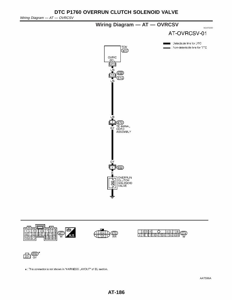
Wiring Diagram — AT — OVRCSVNGAT0200
AAT596A
DTC P1760 OVERRUN CLUTCH SOLENOID VALVEWiring Diagram — AT — OVRCSV
AT-186
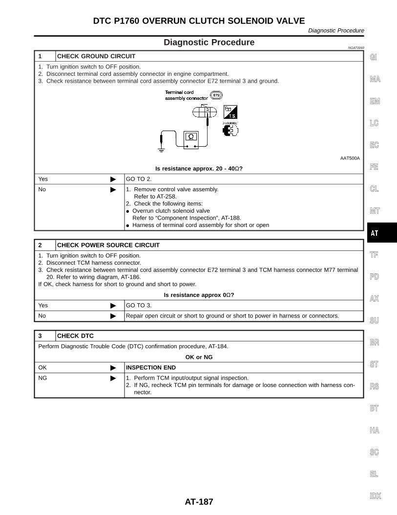
Diagnostic ProcedureNGAT0069
1 CHECK GROUND CIRCUIT
1. Turn ignition switch to OFF position.2. Disconnect terminal cord assembly connector in engine compartment.3. Check resistance between terminal cord assembly connector E72 terminal 3 and ground.
AAT500A
Is resistance approx. 20 - 40 Ω?
Yes © GO TO 2.
No © 1. Remove control valve assembly.Refer to AT-258.
2. Check the following items:I Overrun clutch solenoid valve
Refer to “Component Inspection”, AT-188.I Harness of terminal cord assembly for short or open
2 CHECK POWER SOURCE CIRCUIT
1. Turn ignition switch to OFF position.2. Disconnect TCM harness connector.3. Check resistance between terminal cord assembly connector E72 terminal 3 and TCM harness connector M77 terminal
20. Refer to wiring diagram, AT-186.If OK, check harness for short to ground and short to power.
Is resistance approx 0 Ω?
Yes © GO TO 3.
No © Repair open circuit or short to ground or short to power in harness or connectors.
3 CHECK DTC
Perform Diagnostic Trouble Code (DTC) confirmation procedure, AT-184.
OK or NG
OK © INSPECTION END
NG © 1. Perform TCM input/output signal inspection.2. If NG, recheck TCM pin terminals for damage or loose connection with harness con-
nector.
GI
MA
EM
LC
EC
FE
CL
MT
TF
PD
AX
SU
BR
ST
RS
BT
HA
SC
EL
IDX
DTC P1760 OVERRUN CLUTCH SOLENOID VALVEDiagnostic Procedure
AT-187
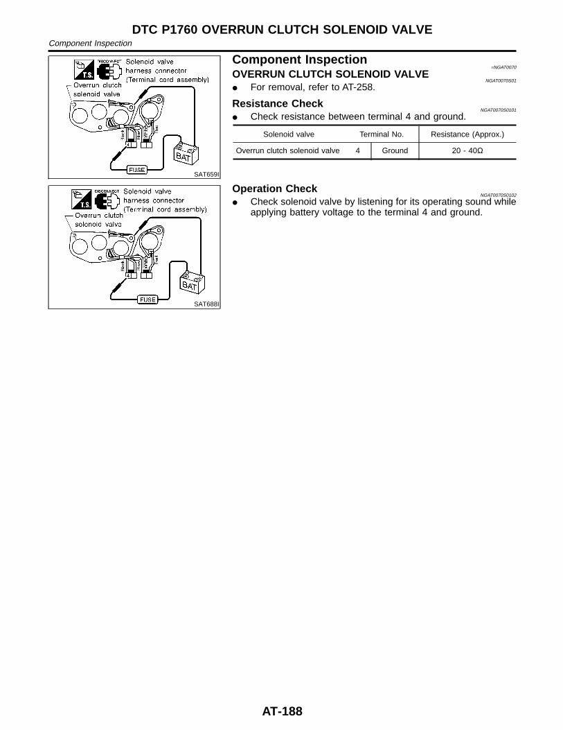
SAT659I
Component Inspection=NGAT0070
OVERRUN CLUTCH SOLENOID VALVENGAT0070S01
I For removal, refer to AT-258.
Resistance CheckNGAT0070S0101
I Check resistance between terminal 4 and ground.
Solenoid valve Terminal No. Resistance (Approx.)
Overrun clutch solenoid valve 4 Ground 20 - 40Ω
SAT688I
Operation CheckNGAT0070S0102
I Check solenoid valve by listening for its operating sound whileapplying battery voltage to the terminal 4 and ground.
DTC P1760 OVERRUN CLUTCH SOLENOID VALVEComponent Inspection
AT-188
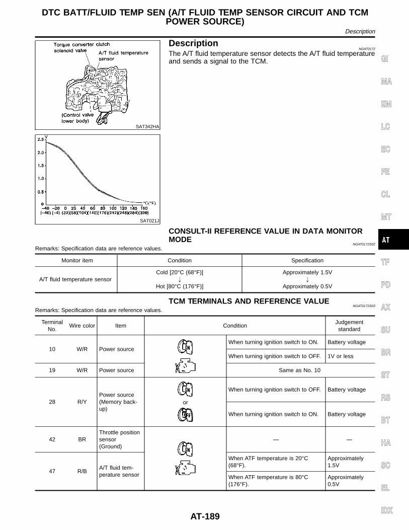
SAT342HA
DescriptionNGAT0172
The A/T fluid temperature sensor detects the A/T fluid temperatureand sends a signal to the TCM.
SAT021J
CONSULT-II REFERENCE VALUE IN DATA MONITORMODE
NGAT0172S02
Remarks: Specification data are reference values.
Monitor item Condition Specification
A/T fluid temperature sensorCold [20°C (68°F)]
"
Hot [80°C (176°F)]
Approximately 1.5V"
Approximately 0.5V
TCM TERMINALS AND REFERENCE VALUENGAT0172S03
Remarks: Specification data are reference values.
TerminalNo.
Wire color Item ConditionJudgementstandard
10 W/R Power sourceWhen turning ignition switch to ON. Battery voltage
When turning ignition switch to OFF. 1V or less
19 W/R Power source Same as No. 10
28 R/YPower source(Memory back-up)
or
When turning ignition switch to OFF. Battery voltage
When turning ignition switch to ON. Battery voltage
42 BRThrottle positionsensor(Ground)
— —
47 R/BA/T fluid tem-perature sensor
When ATF temperature is 20°C(68°F).
Approximately1.5V
When ATF temperature is 80°C(176°F).
Approximately0.5V
GI
MA
EM
LC
EC
FE
CL
MT
TF
PD
AX
SU
BR
ST
RS
BT
HA
SC
EL
IDX
DTC BATT/FLUID TEMP SEN (A/T FLUID TEMP SENSOR CIRCUIT AND TCMPOWER SOURCE)
Description
AT-189
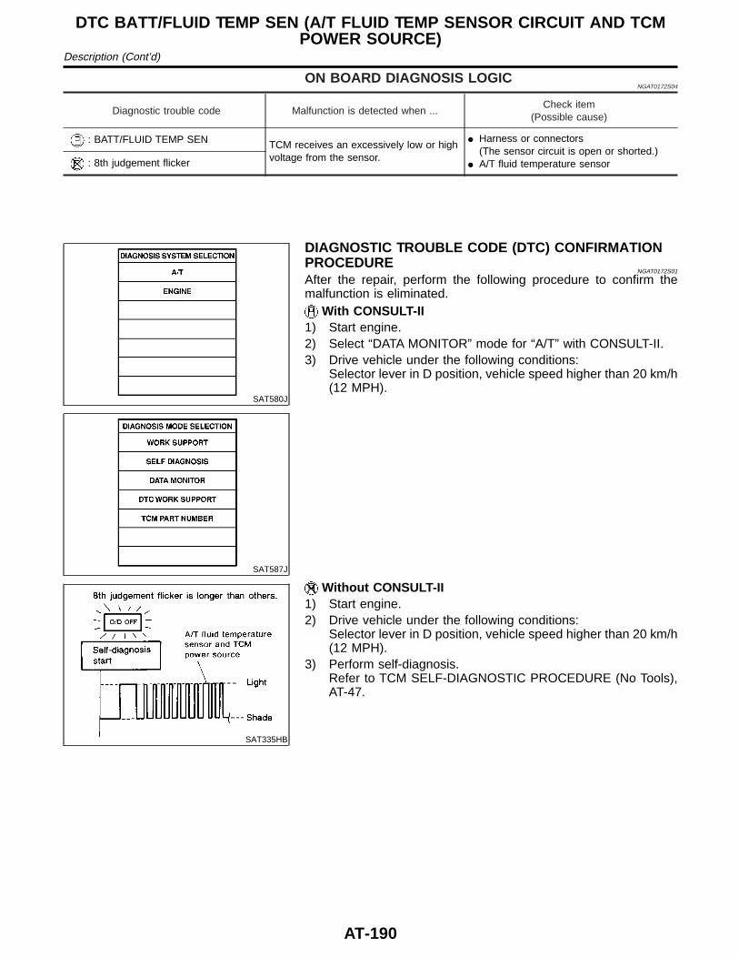
ON BOARD DIAGNOSIS LOGICNGAT0172S04
Diagnostic trouble code Malfunction is detected when ...Check item
(Possible cause)
: BATT/FLUID TEMP SEN TCM receives an excessively low or highvoltage from the sensor.
I Harness or connectors(The sensor circuit is open or shorted.)
I A/T fluid temperature sensor: 8th judgement flicker
SAT580J
SAT587J
DIAGNOSTIC TROUBLE CODE (DTC) CONFIRMATIONPROCEDURE
NGAT0172S01
After the repair, perform the following procedure to confirm themalfunction is eliminated.
With CONSULT-II1) Start engine.2) Select “DATA MONITOR” mode for “A/T” with CONSULT-II.3) Drive vehicle under the following conditions:
Selector lever in D position, vehicle speed higher than 20 km/h(12 MPH).
SAT335HB
Without CONSULT-II1) Start engine.2) Drive vehicle under the following conditions:
Selector lever in D position, vehicle speed higher than 20 km/h(12 MPH).
3) Perform self-diagnosis.Refer to TCM SELF-DIAGNOSTIC PROCEDURE (No Tools),AT-47.
DTC BATT/FLUID TEMP SEN (A/T FLUID TEMP SENSOR CIRCUIT AND TCMPOWER SOURCE)
Description (Cont’d)
AT-190
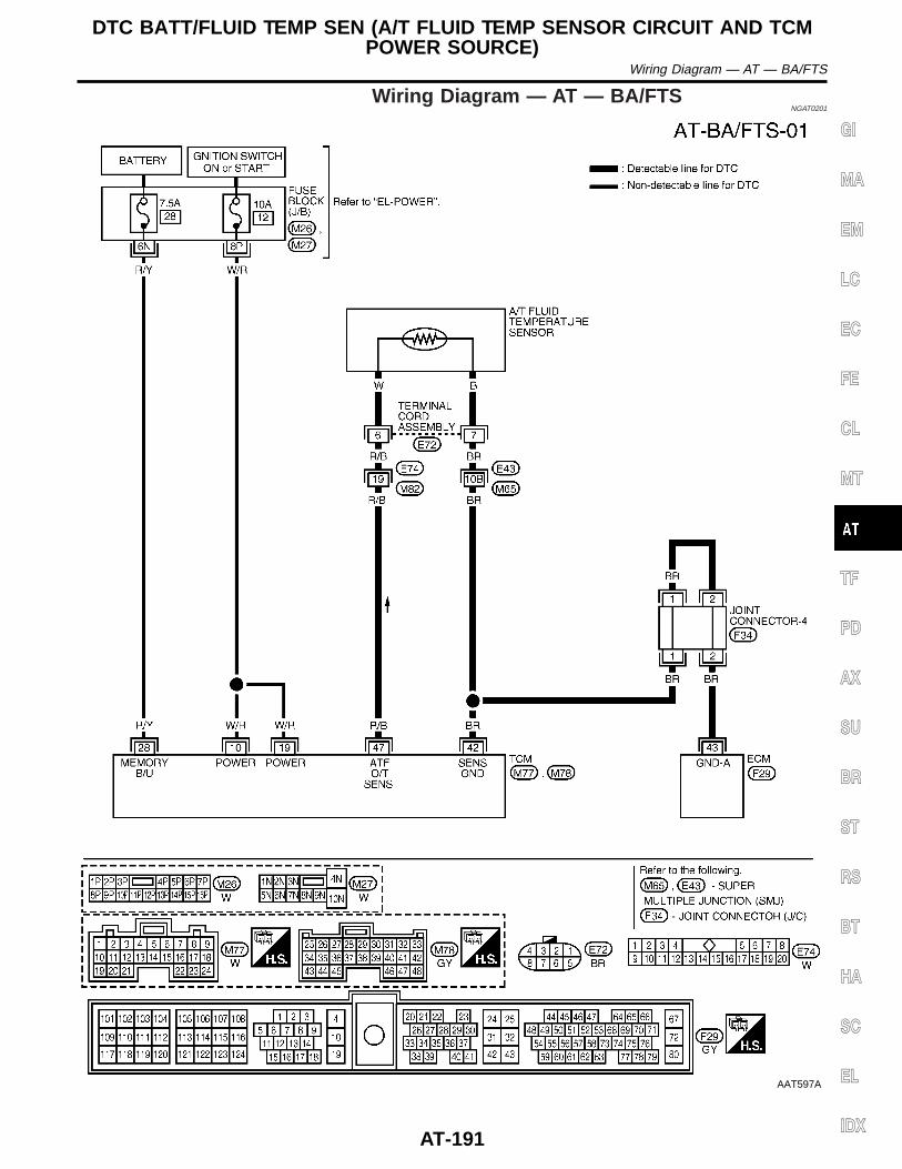
Wiring Diagram — AT — BA/FTSNGAT0201
AAT597A
GI
MA
EM
LC
EC
FE
CL
MT
TF
PD
AX
SU
BR
ST
RS
BT
HA
SC
EL
IDX
DTC BATT/FLUID TEMP SEN (A/T FLUID TEMP SENSOR CIRCUIT AND TCMPOWER SOURCE)
Wiring Diagram — AT — BA/FTS
AT-191
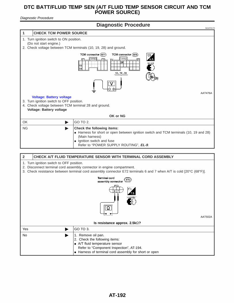
Diagnostic ProcedureNGAT0173
1 CHECK TCM POWER SOURCE
1. Turn ignition switch to ON position.(Do not start engine.)
2. Check voltage between TCM terminals (10, 19, 28) and ground.
AAT476A
Voltage: Battery voltage3. Turn ignition switch to OFF position.4. Check voltage between TCM terminal 28 and ground.
Voltage: Battery voltage
OK or NG
OK © GO TO 2.
NG © Check the following items:I Harness for short or open between ignition switch and TCM terminals (10, 19 and 28)
(Main harness)I Ignition switch and fuse
Refer to “POWER SUPPLY ROUTING”, EL-9.
2 CHECK A/T FLUID TEMPERATURE SENSOR WITH TERMINAL CORD ASSEMBLY
1. Turn ignition switch to OFF position.2. Disconnect terminal cord assembly connector in engine compartment.3. Check resistance between terminal cord assembly connector E72 terminals 6 and 7 when A/T is cold [20°C (68°F)].
AAT502A
Is resistance approx. 2.5k Ω?
Yes © GO TO 3.
No © 1. Remove oil pan.2. Check the following items:I A/T fluid temperature sensor
Refer to “Component Inspection”, AT-194.I Harness of terminal cord assembly for short or open
DTC BATT/FLUID TEMP SEN (A/T FLUID TEMP SENSOR CIRCUIT AND TCMPOWER SOURCE)
Diagnostic Procedure
AT-192
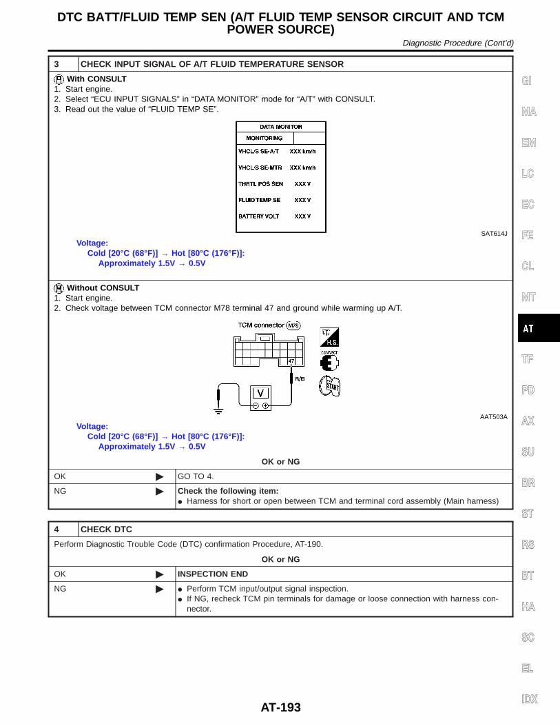
3 CHECK INPUT SIGNAL OF A/T FLUID TEMPERATURE SENSOR
With CONSULT1. Start engine.2. Select “ECU INPUT SIGNALS” in “DATA MONITOR” mode for “A/T” with CONSULT.3. Read out the value of “FLUID TEMP SE”.
SAT614J
Voltage:Cold [20°C (68°F)] → Hot [80°C (176°F)]:
Approximately 1.5V → 0.5V
Without CONSULT1. Start engine.2. Check voltage between TCM connector M78 terminal 47 and ground while warming up A/T.
AAT503A
Voltage:Cold [20°C (68°F)] → Hot [80°C (176°F)]:
Approximately 1.5V → 0.5V
OK or NG
OK © GO TO 4.
NG © Check the following item:I Harness for short or open between TCM and terminal cord assembly (Main harness)
4 CHECK DTC
Perform Diagnostic Trouble Code (DTC) confirmation Procedure, AT-190.
OK or NG
OK © INSPECTION END
NG © I Perform TCM input/output signal inspection.I If NG, recheck TCM pin terminals for damage or loose connection with harness con-
nector.
GI
MA
EM
LC
EC
FE
CL
MT
TF
PD
AX
SU
BR
ST
RS
BT
HA
SC
EL
IDX
DTC BATT/FLUID TEMP SEN (A/T FLUID TEMP SENSOR CIRCUIT AND TCMPOWER SOURCE)
Diagnostic Procedure (Cont’d)
AT-193
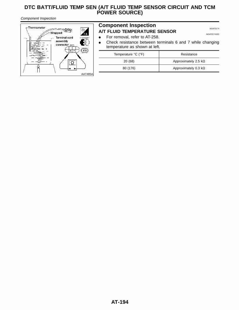
AAT485A
Component InspectionNGAT0174
A/T FLUID TEMPERATURE SENSORNGAT0174S01
I For removal, refer to AT-258.I Check resistance between terminals 6 and 7 while changing
temperature as shown at left.
Temperature °C (°F) Resistance
20 (68) Approximately 2.5 kΩ
80 (176) Approximately 0.3 kΩ
DTC BATT/FLUID TEMP SEN (A/T FLUID TEMP SENSOR CIRCUIT AND TCMPOWER SOURCE)
Component Inspection
AT-194
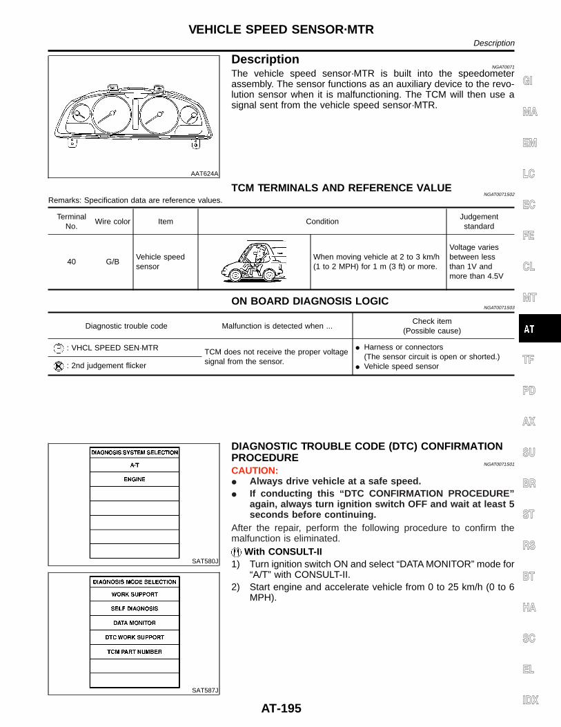
AAT624A
DescriptionNGAT0071
The vehicle speed sensor·MTR is built into the speedometerassembly. The sensor functions as an auxiliary device to the revo-lution sensor when it is malfunctioning. The TCM will then use asignal sent from the vehicle speed sensor·MTR.
TCM TERMINALS AND REFERENCE VALUENGAT0071S02
Remarks: Specification data are reference values.
TerminalNo.
Wire color Item ConditionJudgementstandard
40 G/BVehicle speedsensor
When moving vehicle at 2 to 3 km/h(1 to 2 MPH) for 1 m (3 ft) or more.
Voltage variesbetween lessthan 1V andmore than 4.5V
ON BOARD DIAGNOSIS LOGICNGAT0071S03
Diagnostic trouble code Malfunction is detected when ...Check item
(Possible cause)
: VHCL SPEED SEN·MTR TCM does not receive the proper voltagesignal from the sensor.
I Harness or connectors(The sensor circuit is open or shorted.)
I Vehicle speed sensor: 2nd judgement flicker
SAT580J
SAT587J
DIAGNOSTIC TROUBLE CODE (DTC) CONFIRMATIONPROCEDURE
NGAT0071S01
CAUTION:I Always drive vehicle at a safe speed.I If conducting this “DTC CONFIRMATION PROCEDURE”
again, always turn ignition switch OFF and wait at least 5seconds before continuing.
After the repair, perform the following procedure to confirm themalfunction is eliminated.
With CONSULT-II1) Turn ignition switch ON and select “DATA MONITOR” mode for
“A/T” with CONSULT-II.2) Start engine and accelerate vehicle from 0 to 25 km/h (0 to 6
MPH).
GI
MA
EM
LC
EC
FE
CL
MT
TF
PD
AX
SU
BR
ST
RS
BT
HA
SC
EL
IDX
VEHICLE SPEED SENSOR·MTRDescription
AT-195
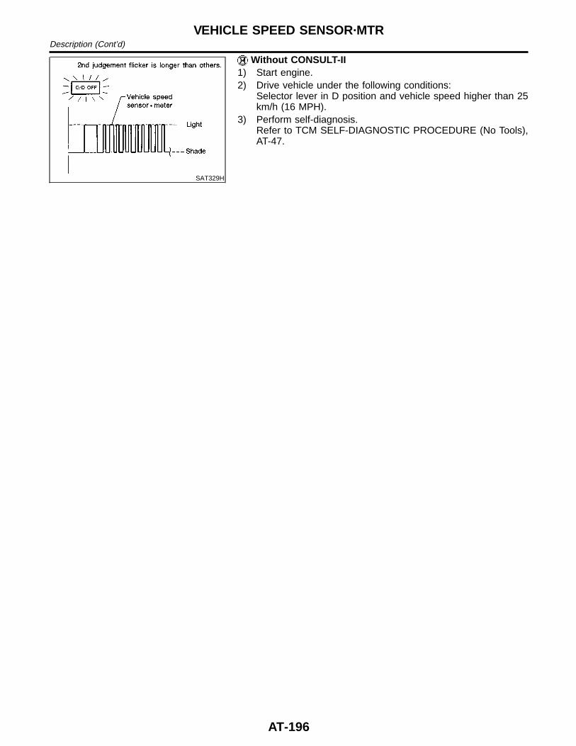
SAT329H
Without CONSULT-II1) Start engine.2) Drive vehicle under the following conditions:
Selector lever in D position and vehicle speed higher than 25km/h (16 MPH).
3) Perform self-diagnosis.Refer to TCM SELF-DIAGNOSTIC PROCEDURE (No Tools),AT-47.
VEHICLE SPEED SENSOR·MTRDescription (Cont’d)
AT-196
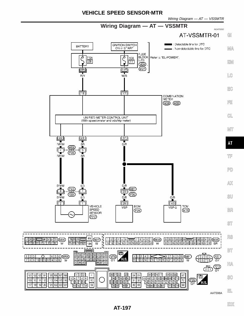
Wiring Diagram — AT — VSSMTRNGAT0202
AAT598A
GI
MA
EM
LC
EC
FE
CL
MT
TF
PD
AX
SU
BR
ST
RS
BT
HA
SC
EL
IDX
VEHICLE SPEED SENSOR·MTRWiring Diagram — AT — VSSMTR
AT-197
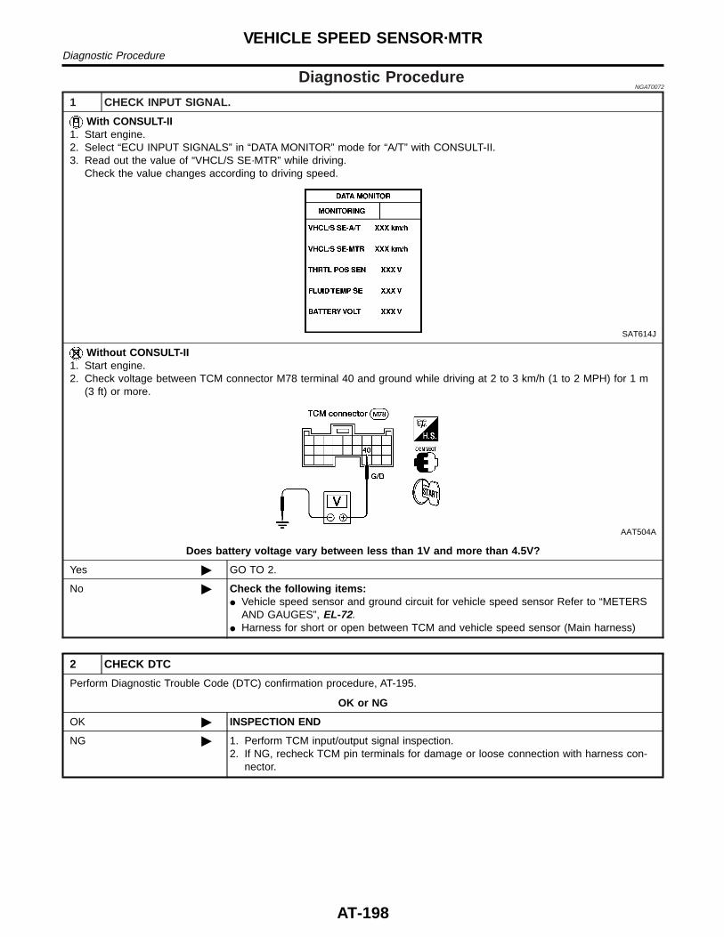
Diagnostic ProcedureNGAT0072
1 CHECK INPUT SIGNAL.
With CONSULT-II1. Start engine.2. Select “ECU INPUT SIGNALS” in “DATA MONITOR” mode for “A/T” with CONSULT-II.3. Read out the value of “VHCL/S SE·MTR” while driving.
Check the value changes according to driving speed.
SAT614J
Without CONSULT-II1. Start engine.2. Check voltage between TCM connector M78 terminal 40 and ground while driving at 2 to 3 km/h (1 to 2 MPH) for 1 m
(3 ft) or more.
AAT504A
Does battery voltage vary between less than 1V and more than 4.5V?
Yes © GO TO 2.
No © Check the following items:I Vehicle speed sensor and ground circuit for vehicle speed sensor Refer to “METERS
AND GAUGES”, EL-72.I Harness for short or open between TCM and vehicle speed sensor (Main harness)
2 CHECK DTC
Perform Diagnostic Trouble Code (DTC) confirmation procedure, AT-195.
OK or NG
OK © INSPECTION END
NG © 1. Perform TCM input/output signal inspection.2. If NG, recheck TCM pin terminals for damage or loose connection with harness con-
nector.
VEHICLE SPEED SENSOR·MTRDiagnostic Procedure
AT-198
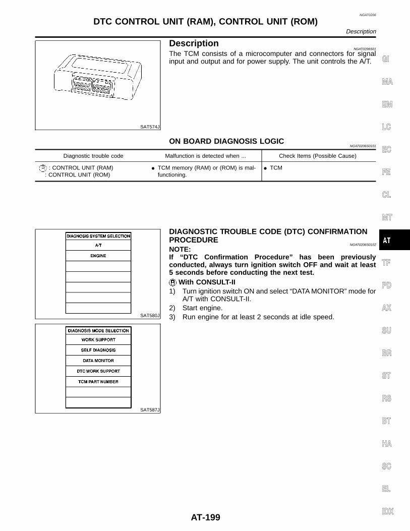
NGAT0206
SAT574J
DescriptionNGAT0206S01
The TCM consists of a microcomputer and connectors for signalinput and output and for power supply. The unit controls the A/T.
ON BOARD DIAGNOSIS LOGICNGAT0206S0101
Diagnostic trouble code Malfunction is detected when ... Check Items (Possible Cause)
: CONTROL UNIT (RAM): CONTROL UNIT (ROM)
I TCM memory (RAM) or (ROM) is mal-functioning.
I TCM
SAT580J
SAT587J
DIAGNOSTIC TROUBLE CODE (DTC) CONFIRMATIONPROCEDURE
NGAT0206S0102
NOTE:If “DTC Confirmation Procedure” has been previouslyconducted, always turn ignition switch OFF and wait at least5 seconds before conducting the next test.
With CONSULT-II1) Turn ignition switch ON and select “DATA MONITOR” mode for
A/T with CONSULT-II.2) Start engine.3) Run engine for at least 2 seconds at idle speed.
GI
MA
EM
LC
EC
FE
CL
MT
TF
PD
AX
SU
BR
ST
RS
BT
HA
SC
EL
IDX
DTC CONTROL UNIT (RAM), CONTROL UNIT (ROM)Description
AT-199
Diagnostic Procedure=NGAT0206S04
1 INSPECTION START
With CONSULT-II1. Turn ignition switch ON and select “SELF DIAG RESULTS” mode for A/T with CONSULT-II.2. Touch “ERASE”.3. Perform “DIAGNOSTIC TROUBLE CODE (DTC) CONFIRMATION PROCEDURE”, refer to AT-199.4. Is the “CONTROL UNIT (RAM)” or “CONTROL UNIT (ROM)” displayed again?
Yes or No
Yes © Replace TCM.
No © INSPECTION END
DTC CONTROL UNIT (RAM), CONTROL UNIT (ROM)Diagnostic Procedure
AT-200
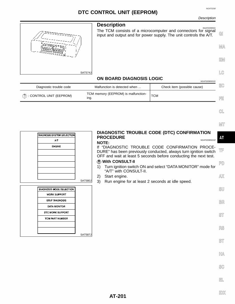
NGAT0208
SAT574J
DescriptionNGAT0208S01
The TCM consists of a microcomputer and connectors for signalinput and output and for power supply. The unit controls the A/T.
ON BOARD DIAGNOSIS LOGICNGAT0208S0101
Diagnostic trouble code Malfunction is detected when ... Check item (possible cause)
: CONTROL UNIT (EEPROM)TCM memory (EEPROM) is malfunction-ing.
TCM
SAT580J
SAT587J
DIAGNOSTIC TROUBLE CODE (DTC) CONFIRMATIONPROCEDURE
NGAT0208S0102
NOTE:If “DIAGNOSTIC TROUBLE CODE CONFIRMATION PROCE-DURE” has been previously conducted, always turn ignition switchOFF and wait at least 5 seconds before conducting the next test.
With CONSULT-II1) Turn ignition switch ON and select “DATA MONITOR” mode for
“A/T” with CONSULT-II.2) Start engine.3) Run engine for at least 2 seconds at idle speed.
GI
MA
EM
LC
EC
FE
CL
MT
TF
PD
AX
SU
BR
ST
RS
BT
HA
SC
EL
IDX
DTC CONTROL UNIT (EEPROM)Description
AT-201
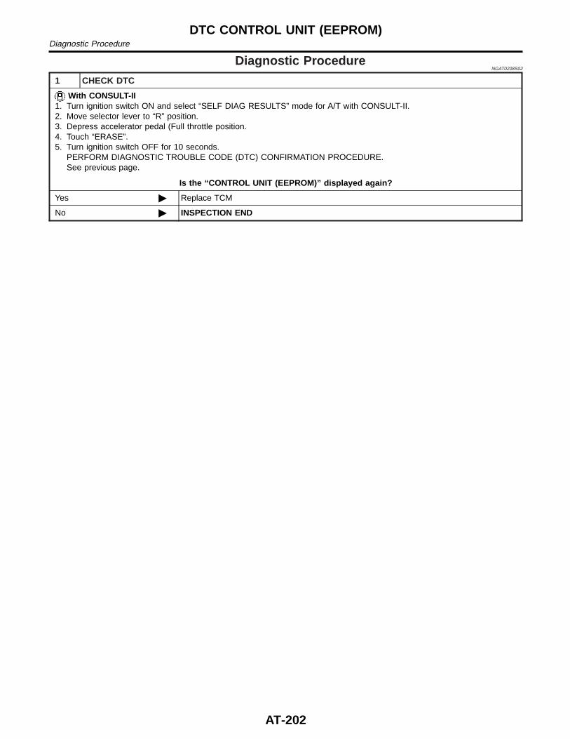
Diagnostic ProcedureNGAT0208S02
1 CHECK DTC
With CONSULT-II1. Turn ignition switch ON and select “SELF DIAG RESULTS” mode for A/T with CONSULT-II.2. Move selector lever to “R” position.3. Depress accelerator pedal (Full throttle position.4. Touch “ERASE”.5. Turn ignition switch OFF for 10 seconds.
PERFORM DIAGNOSTIC TROUBLE CODE (DTC) CONFIRMATION PROCEDURE.See previous page.
Is the “CONTROL UNIT (EEPROM)” displayed again?
Yes © Replace TCM
No © INSPECTION END
DTC CONTROL UNIT (EEPROM)Diagnostic Procedure
AT-202
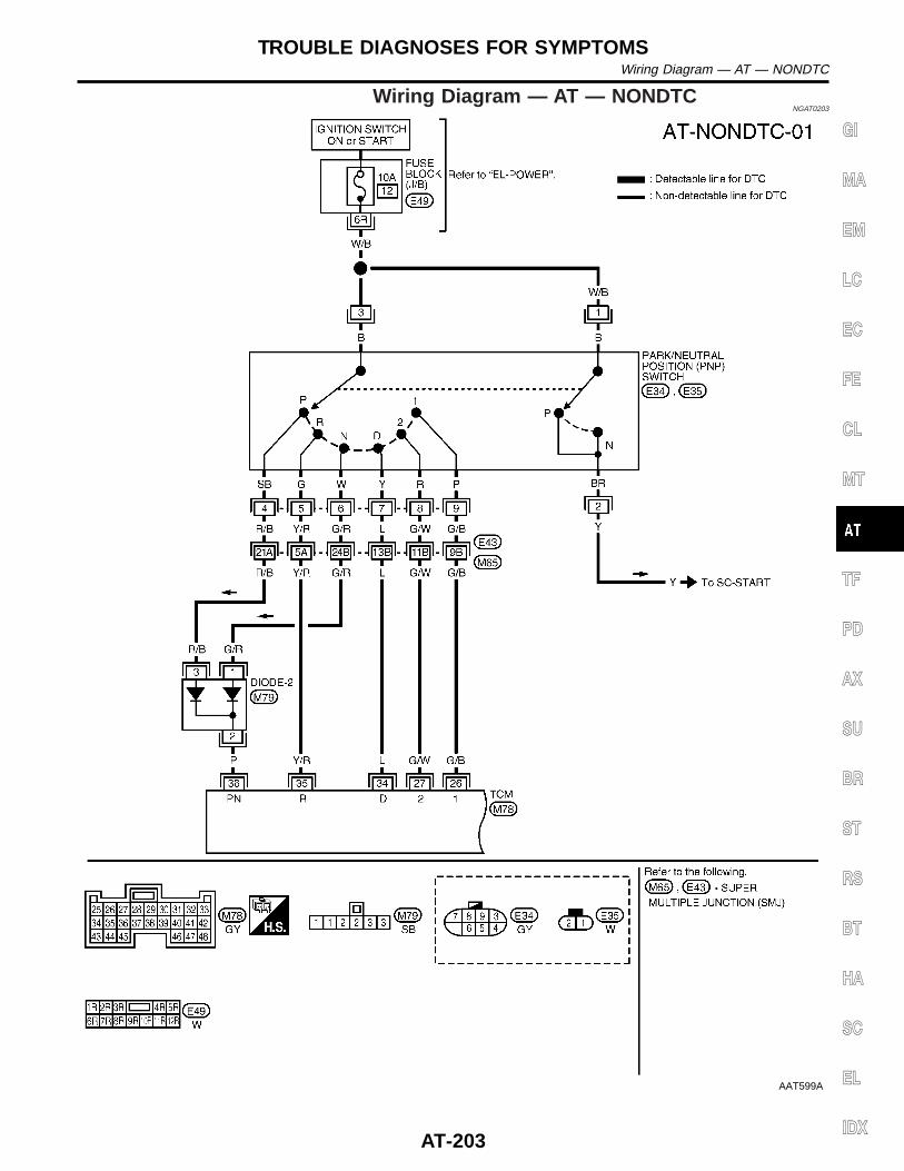
Wiring Diagram — AT — NONDTCNGAT0203
AAT599A
GI
MA
EM
LC
EC
FE
CL
MT
TF
PD
AX
SU
BR
ST
RS
BT
HA
SC
EL
IDX
TROUBLE DIAGNOSES FOR SYMPTOMSWiring Diagram — AT — NONDTC
AT-203
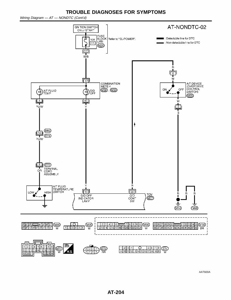
AAT600A
TROUBLE DIAGNOSES FOR SYMPTOMSWiring Diagram — AT — NONDTC (Cont’d)
AT-204
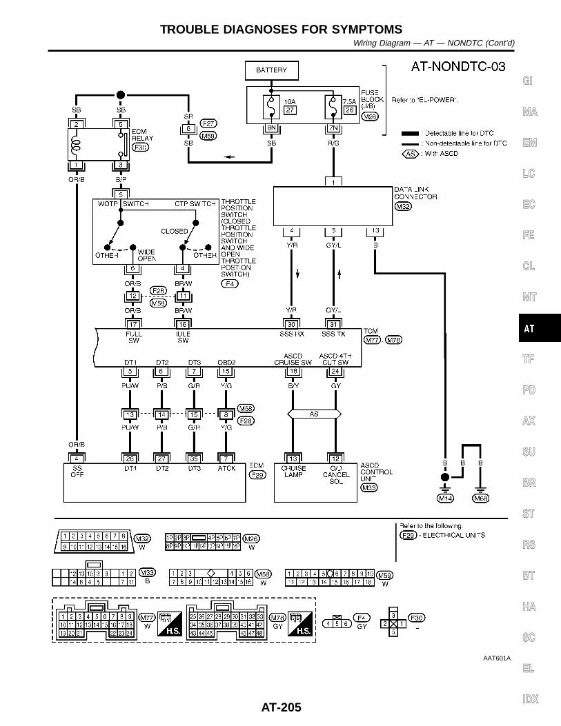
AAT601A
GI
MA
EM
LC
EC
FE
CL
MT
TF
PD
AX
SU
BR
ST
RS
BT
HA
SC
EL
IDX
TROUBLE DIAGNOSES FOR SYMPTOMSWiring Diagram — AT — NONDTC (Cont’d)
AT-205
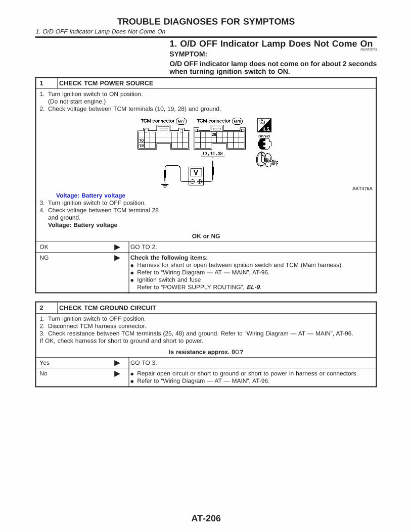
1. O/D OFF Indicator Lamp Does Not Come OnNGAT0073
SYMPTOM:O/D OFF indicator lamp does not come on for about 2 secondswhen turning ignition switch to ON.
1 CHECK TCM POWER SOURCE
1. Turn ignition switch to ON position.(Do not start engine.)
2. Check voltage between TCM terminals (10, 19, 28) and ground.
AAT476A
Voltage: Battery voltage3. Turn ignition switch to OFF position.4. Check voltage between TCM terminal 28
and ground.Voltage: Battery voltage
OK or NG
OK © GO TO 2.
NG © Check the following items:I Harness for short or open between ignition switch and TCM (Main harness)I Refer to “Wiring Diagram — AT — MAIN”, AT-96.I Ignition switch and fuse
Refer to “POWER SUPPLY ROUTING”, EL-9.
2 CHECK TCM GROUND CIRCUIT
1. Turn ignition switch to OFF position.2. Disconnect TCM harness connector.3. Check resistance between TCM terminals (25, 48) and ground. Refer to “Wiring Diagram — AT — MAIN”, AT-96.If OK, check harness for short to ground and short to power.
Is resistance approx. 0 Ω?
Yes © GO TO 3.
No © I Repair open circuit or short to ground or short to power in harness or connectors.I Refer to “Wiring Diagram — AT — MAIN”, AT-96.
TROUBLE DIAGNOSES FOR SYMPTOMS1. O/D OFF Indicator Lamp Does Not Come On
AT-206
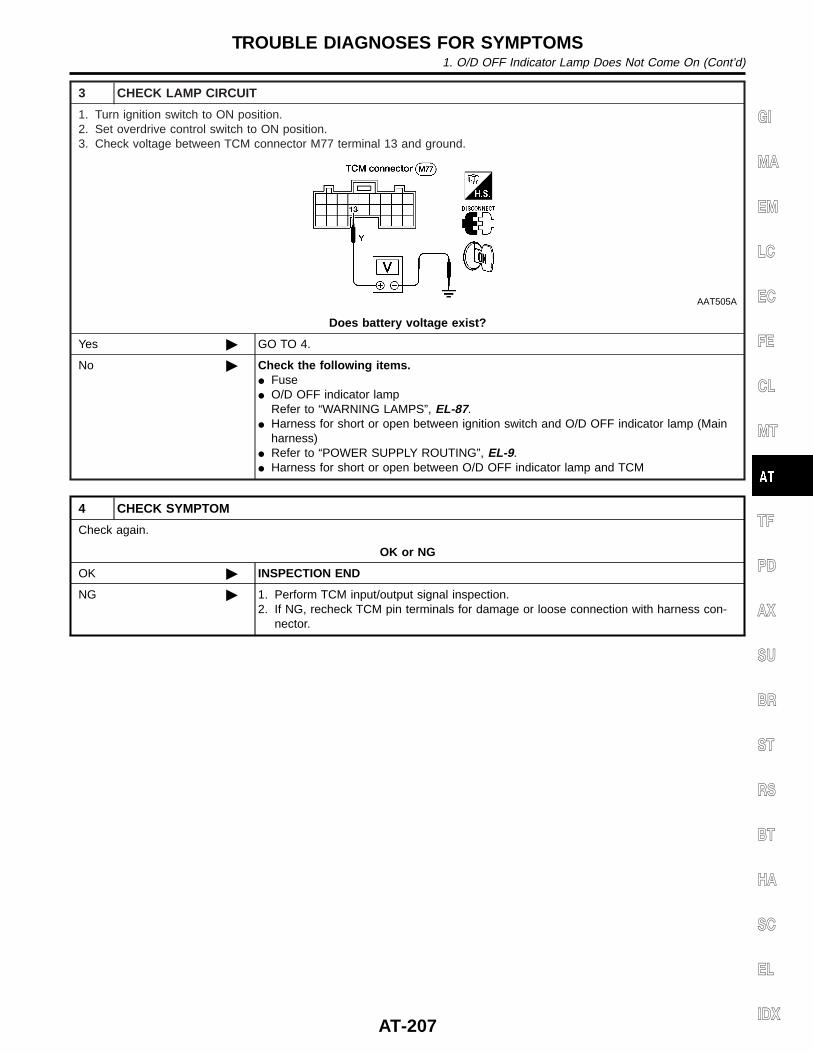
3 CHECK LAMP CIRCUIT
1. Turn ignition switch to ON position.2. Set overdrive control switch to ON position.3. Check voltage between TCM connector M77 terminal 13 and ground.
AAT505A
Does battery voltage exist?
Yes © GO TO 4.
No © Check the following items.I FuseI O/D OFF indicator lamp
Refer to “WARNING LAMPS”, EL-87.I Harness for short or open between ignition switch and O/D OFF indicator lamp (Main
harness)I Refer to “POWER SUPPLY ROUTING”, EL-9.I Harness for short or open between O/D OFF indicator lamp and TCM
4 CHECK SYMPTOM
Check again.
OK or NG
OK © INSPECTION END
NG © 1. Perform TCM input/output signal inspection.2. If NG, recheck TCM pin terminals for damage or loose connection with harness con-
nector.
GI
MA
EM
LC
EC
FE
CL
MT
TF
PD
AX
SU
BR
ST
RS
BT
HA
SC
EL
IDX
TROUBLE DIAGNOSES FOR SYMPTOMS1. O/D OFF Indicator Lamp Does Not Come On (Cont’d)
AT-207
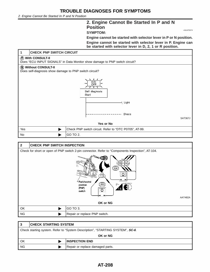
2. Engine Cannot Be Started In P and NPosition
=NGAT0074
SYMPTOM:Engine cannot be started with selector lever in P or N position.Engine cannot be started with selector lever in P. Engine canbe started with selector lever in D, 2, 1 or R position.
1 CHECK PNP SWITCH CIRCUIT
With CONSULT-IIDoes “ECU INPUT SIGNALS” in Data Monitor show damage to PNP switch circuit?
Without CONSULT-IIDoes self-diagnosis show damage to PNP switch circuit?
SAT367J
Yes or No
Yes © Check PNP switch circuit. Refer to “DTC P0705”, AT-99.
No © GO TO 2.
2 CHECK PNP SWITCH INSPECTION
Check for short or open of PNP switch 2-pin connector. Refer to “Components Inspection”, AT-104.
AAT482A
OK or NG
OK © GO TO 3.
NG © Repair or replace PNP switch.
3 CHECK STARTING SYSTEM
Check starting system. Refer to “System Description”, “STARTING SYSTEM”, SC-6.
OK or NG
OK © INSPECTION END
NG © Repair or replace damaged parts.
TROUBLE DIAGNOSES FOR SYMPTOMS2. Engine Cannot Be Started In P and N Position
AT-208
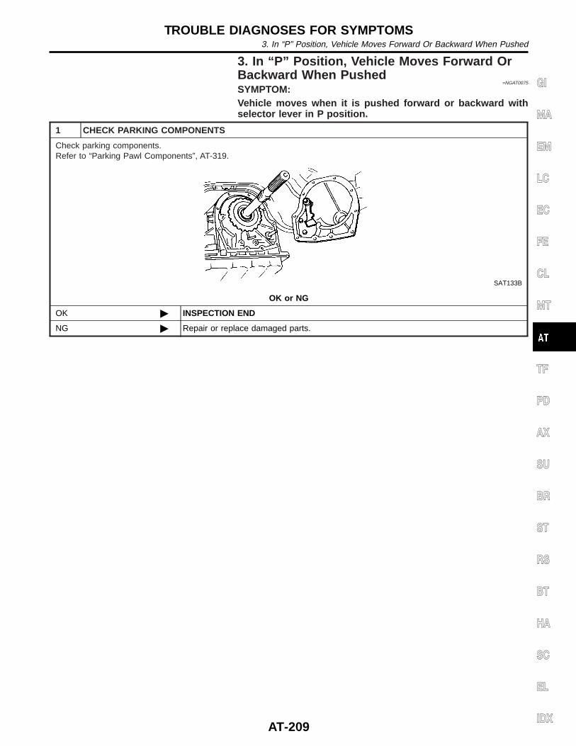
3. In “P” Position, Vehicle Moves Forward OrBackward When Pushed
=NGAT0075
SYMPTOM:Vehicle moves when it is pushed forward or backward withselector lever in P position.
1 CHECK PARKING COMPONENTS
Check parking components.Refer to “Parking Pawl Components”, AT-319.
SAT133B
OK or NG
OK © INSPECTION END
NG © Repair or replace damaged parts.
GI
MA
EM
LC
EC
FE
CL
MT
TF
PD
AX
SU
BR
ST
RS
BT
HA
SC
EL
IDX
TROUBLE DIAGNOSES FOR SYMPTOMS3. In “P” Position, Vehicle Moves Forward Or Backward When Pushed
AT-209
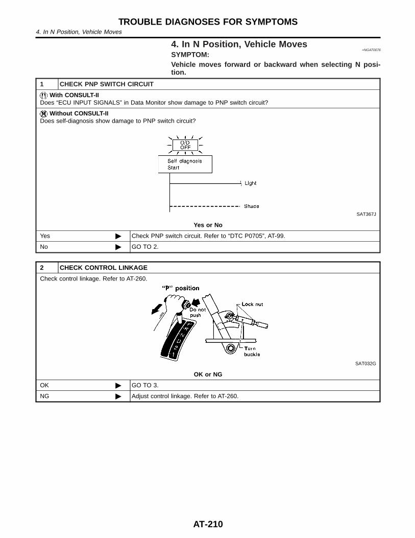
4. In N Position, Vehicle Moves=NGAT0076
SYMPTOM:Vehicle moves forward or backward when selecting N posi-tion.
1 CHECK PNP SWITCH CIRCUIT
With CONSULT-IIDoes “ECU INPUT SIGNALS” in Data Monitor show damage to PNP switch circuit?
Without CONSULT-IIDoes self-diagnosis show damage to PNP switch circuit?
SAT367J
Yes or No
Yes © Check PNP switch circuit. Refer to “DTC P0705”, AT-99.
No © GO TO 2.
2 CHECK CONTROL LINKAGE
Check control linkage. Refer to AT-260.
SAT032G
OK or NG
OK © GO TO 3.
NG © Adjust control linkage. Refer to AT-260.
TROUBLE DIAGNOSES FOR SYMPTOMS4. In N Position, Vehicle Moves
AT-210
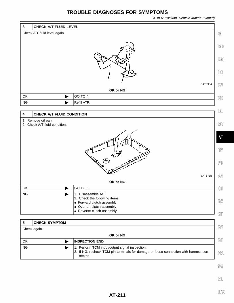
3 CHECK A/T FLUID LEVEL
Check A/T fluid level again.
SAT638A
OK or NG
OK © GO TO 4.
NG © Refill ATF.
4 CHECK A/T FLUID CONDITION
1. Remove oil pan.2. Check A/T fluid condition.
SAT171B
OK or NG
OK © GO TO 5.
NG © 1. Disassemble A/T.2. Check the following items:I Forward clutch assemblyI Overrun clutch assemblyI Reverse clutch assembly
5 CHECK SYMPTOM
Check again.
OK or NG
OK © INSPECTION END
NG © 1. Perform TCM input/output signal inspection.2. If NG, recheck TCM pin terminals for damage or loose connection with harness con-
nector.
GI
MA
EM
LC
EC
FE
CL
MT
TF
PD
AX
SU
BR
ST
RS
BT
HA
SC
EL
IDX
TROUBLE DIAGNOSES FOR SYMPTOMS4. In N Position, Vehicle Moves (Cont’d)
AT-211
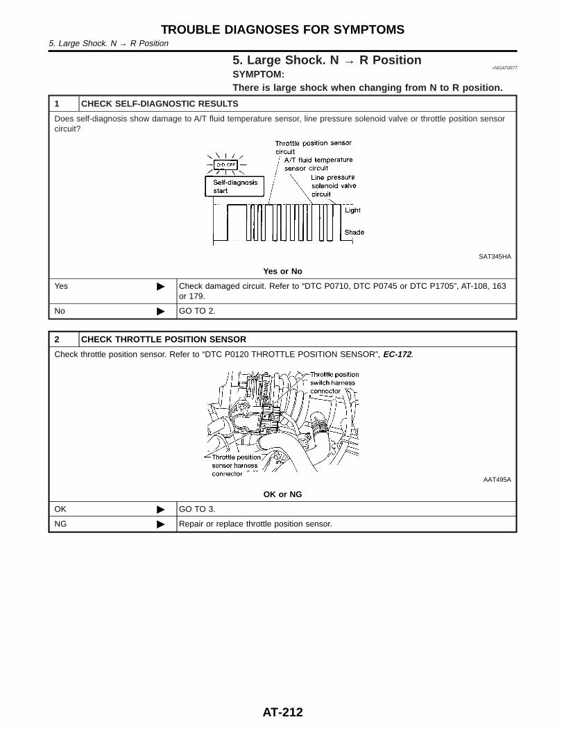
5. Large Shock. N → R Position=NGAT0077
SYMPTOM:There is large shock when changing from N to R position.
1 CHECK SELF-DIAGNOSTIC RESULTS
Does self-diagnosis show damage to A/T fluid temperature sensor, line pressure solenoid valve or throttle position sensorcircuit?
SAT345HA
Yes or No
Yes © Check damaged circuit. Refer to “DTC P0710, DTC P0745 or DTC P1705”, AT-108, 163or 179.
No © GO TO 2.
2 CHECK THROTTLE POSITION SENSOR
Check throttle position sensor. Refer to “DTC P0120 THROTTLE POSITION SENSOR”, EC-172.
AAT495A
OK or NG
OK © GO TO 3.
NG © Repair or replace throttle position sensor.
TROUBLE DIAGNOSES FOR SYMPTOMS5. Large Shock. N → R Position
AT-212
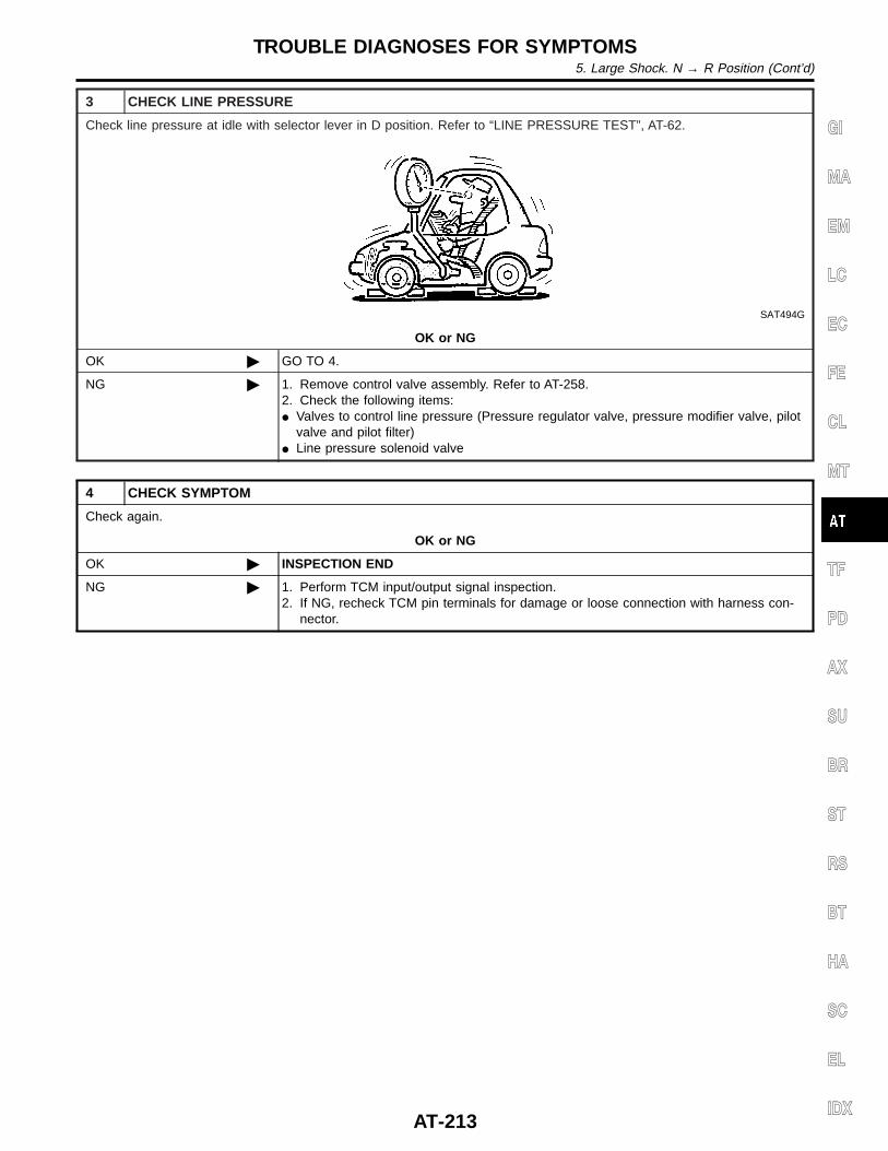
3 CHECK LINE PRESSURE
Check line pressure at idle with selector lever in D position. Refer to “LINE PRESSURE TEST”, AT-62.
SAT494G
OK or NG
OK © GO TO 4.
NG © 1. Remove control valve assembly. Refer to AT-258.2. Check the following items:I Valves to control line pressure (Pressure regulator valve, pressure modifier valve, pilot
valve and pilot filter)I Line pressure solenoid valve
4 CHECK SYMPTOM
Check again.
OK or NG
OK © INSPECTION END
NG © 1. Perform TCM input/output signal inspection.2. If NG, recheck TCM pin terminals for damage or loose connection with harness con-
nector.
GI
MA
EM
LC
EC
FE
CL
MT
TF
PD
AX
SU
BR
ST
RS
BT
HA
SC
EL
IDX
TROUBLE DIAGNOSES FOR SYMPTOMS5. Large Shock. N → R Position (Cont’d)
AT-213
6. Vehicle Does Not Creep Backward In RPosition
=NGAT0078
SYMPTOM:Vehicle does not creep backward when selecting R position.
1 CHECK A/T FLUID LEVEL
Check A/T fluid level again.
SAT638A
OK or NG
OK © GO TO 2.
NG © Refill ATF.
2 CHECK STALL TEST
Check stall revolution with selector lever in 1 and R positions.Refer to AT-338.
SAT493G
OK or NG
OK © GO TO 3.
OK in “1” position, NG inR position
© 1. Remove control valve assembly. Refer to “ON-VEHICLE SERVICE”, AT-258.2. Check the following items:I Valves to control line pressure (Pressure regulator valve, pressure modifier valve, pilot
valve and pilot filter)I Line pressure solenoid valve3. Disassemble A/T.4. Check the following items:I Oil pump assemblyI Torque converterI Reverse clutch assemblyI High clutch assembly
NG in both 1 and Rpositions
© GO TO 6.
TROUBLE DIAGNOSES FOR SYMPTOMS6. Vehicle Does Not Creep Backward In R Position
AT-214
3 CHECK LINE PRESSURE
Check line pressure at idle with selector lever in R position. Refer to “LINE PRESSURE TEST”, AT-62.
SAT494G
OK or NG
OK © GO TO 4.
NG © 1. Remove control valve assembly. Refer to “ON-VEHICLE SERVICE”, AT-258.2. Check the following items:I Valves to control line pressure (Pressure regulator valve, pressure modifier valve, pilot
valve and pilot filter)I Line pressure solenoid valve3. Disassemble A/T.4. Check the following items:I Oil pump assembly
4 CHECK A/T FLUID CONDITION
1. Remove oil pan.2. Check A/T fluid condition.
SAT171B
OK or NG
OK © GO TO 5.
NG © GO TO 6.
5 CHECK SYMPTOM
Check again.
OK or NG
OK © INSPECTION END
NG © 1. Perform TCM input/output signal inspection.2. If NG, recheck TCM pin terminals for damage or loose connection with harness con-
nector.
GI
MA
EM
LC
EC
FE
CL
MT
TF
PD
AX
SU
BR
ST
RS
BT
HA
SC
EL
IDX
TROUBLE DIAGNOSES FOR SYMPTOMS6. Vehicle Does Not Creep Backward In R Position (Cont’d)
AT-215
6 DETECT MALFUNCTIONING ITEM
1. Remove control valve assembly. Refer to “ON-VEHICLE SERVICE”, AT-258.2. Check the following items:I Valves to control line pressure (Pressure regulator valve, pressure modifier valve, pilot valve and pilot filter)I Line pressure solenoid valve3. Disassemble A/T.4. Check the following items:I Oil pump assemblyI Torque converterI Reverse clutch assemblyI High clutch assemblyI Low & reverse brake assemblyI Low one-way clutch
© Repair or replace damaged parts.
TROUBLE DIAGNOSES FOR SYMPTOMS6. Vehicle Does Not Creep Backward In R Position (Cont’d)
AT-216
7. Vehicle Does Not Creep Forward In D, 2 Or 1Position
=NGAT0079
SYMPTOM:Vehicle does not creep forward when selecting D, 2 or 1 posi-tion.
1 CHECK A/T FLUID LEVEL
Check A/T fluid level again.
SAT638A
OK or NG
OK © GO TO 2.
NG © Refill ATF.
2 CHECK STALL TEST
Check stall revolution with selector lever in D position.Refer to “STALL TEST”, AT-59.
SAT493G
OK or NG
OK © GO TO 3.
NG © GO TO 6.
GI
MA
EM
LC
EC
FE
CL
MT
TF
PD
AX
SU
BR
ST
RS
BT
HA
SC
EL
IDX
TROUBLE DIAGNOSES FOR SYMPTOMS7. Vehicle Does Not Creep Forward In D, 2 Or 1 Position
AT-217
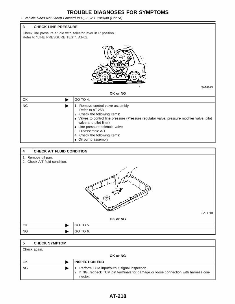
3 CHECK LINE PRESSURE
Check line pressure at idle with selector lever in R position.Refer to “LINE PRESSURE TEST”, AT-62.
SAT494G
OK or NG
OK © GO TO 4.
NG © 1. Remove control valve assembly.Refer to AT-258.
2. Check the following items:I Valves to control line pressure (Pressure regulator valve, pressure modifier valve, pilot
valve and pilot filter)I Line pressure solenoid valve3. Disassemble A/T.4. Check the following items:I Oil pump assembly
4 CHECK A/T FLUID CONDITION
1. Remove oil pan.2. Check A/T fluid condition.
SAT171B
OK or NG
OK © GO TO 5.
NG © GO TO 6.
5 CHECK SYMPTOM
Check again.
OK or NG
OK © INSPECTION END
NG © 1. Perform TCM input/output signal inspection.2. If NG, recheck TCM pin terminals for damage or loose connection with harness con-
nector.
TROUBLE DIAGNOSES FOR SYMPTOMS7. Vehicle Does Not Creep Forward In D, 2 Or 1 Position (Cont’d)
AT-218
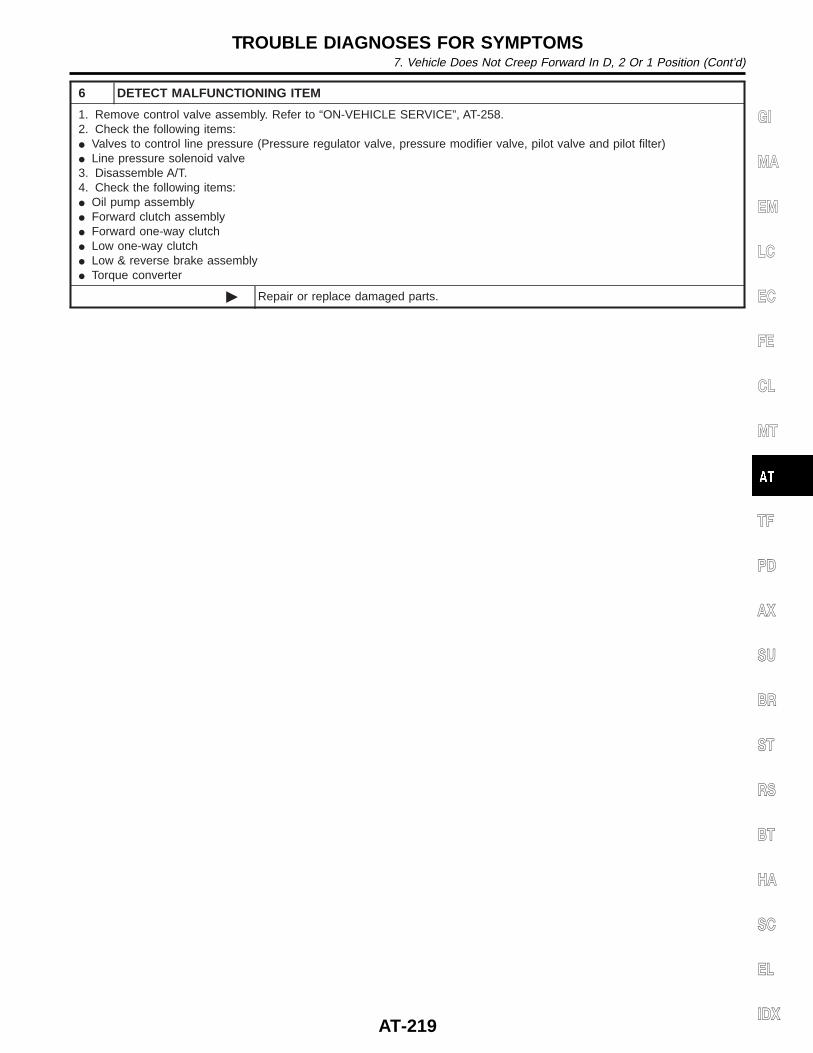
6 DETECT MALFUNCTIONING ITEM
1. Remove control valve assembly. Refer to “ON-VEHICLE SERVICE”, AT-258.2. Check the following items:I Valves to control line pressure (Pressure regulator valve, pressure modifier valve, pilot valve and pilot filter)I Line pressure solenoid valve3. Disassemble A/T.4. Check the following items:I Oil pump assemblyI Forward clutch assemblyI Forward one-way clutchI Low one-way clutchI Low & reverse brake assemblyI Torque converter
© Repair or replace damaged parts.
GI
MA
EM
LC
EC
FE
CL
MT
TF
PD
AX
SU
BR
ST
RS
BT
HA
SC
EL
IDX
TROUBLE DIAGNOSES FOR SYMPTOMS7. Vehicle Does Not Creep Forward In D, 2 Or 1 Position (Cont’d)
AT-219
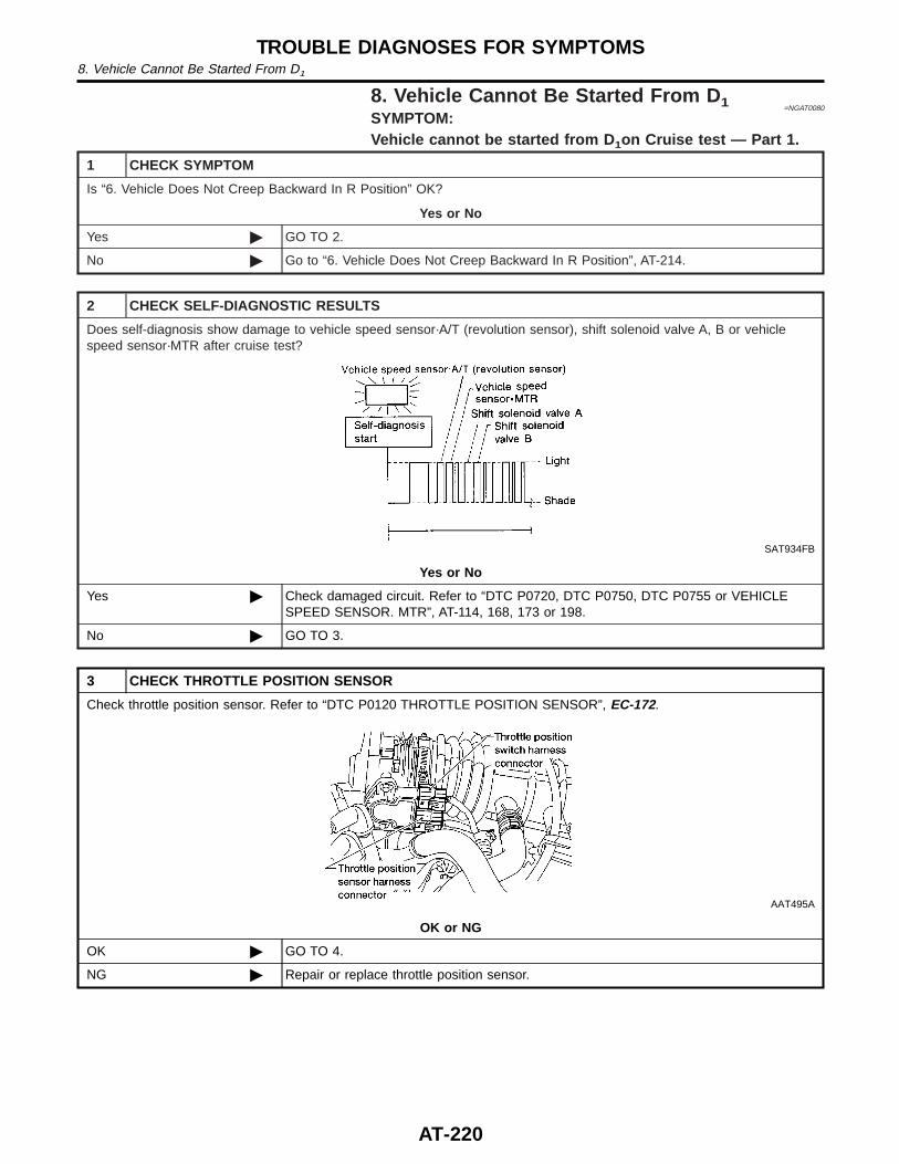
8. Vehicle Cannot Be Started From D 1 =NGAT0080
SYMPTOM:Vehicle cannot be started from D 1on Cruise test — Part 1.
1 CHECK SYMPTOM
Is “6. Vehicle Does Not Creep Backward In R Position” OK?
Yes or No
Yes © GO TO 2.
No © Go to “6. Vehicle Does Not Creep Backward In R Position”, AT-214.
2 CHECK SELF-DIAGNOSTIC RESULTS
Does self-diagnosis show damage to vehicle speed sensor·A/T (revolution sensor), shift solenoid valve A, B or vehiclespeed sensor·MTR after cruise test?
SAT934FB
Yes or No
Yes © Check damaged circuit. Refer to “DTC P0720, DTC P0750, DTC P0755 or VEHICLESPEED SENSOR. MTR”, AT-114, 168, 173 or 198.
No © GO TO 3.
3 CHECK THROTTLE POSITION SENSOR
Check throttle position sensor. Refer to “DTC P0120 THROTTLE POSITION SENSOR”, EC-172.
AAT495A
OK or NG
OK © GO TO 4.
NG © Repair or replace throttle position sensor.
TROUBLE DIAGNOSES FOR SYMPTOMS8. Vehicle Cannot Be Started From D1
AT-220
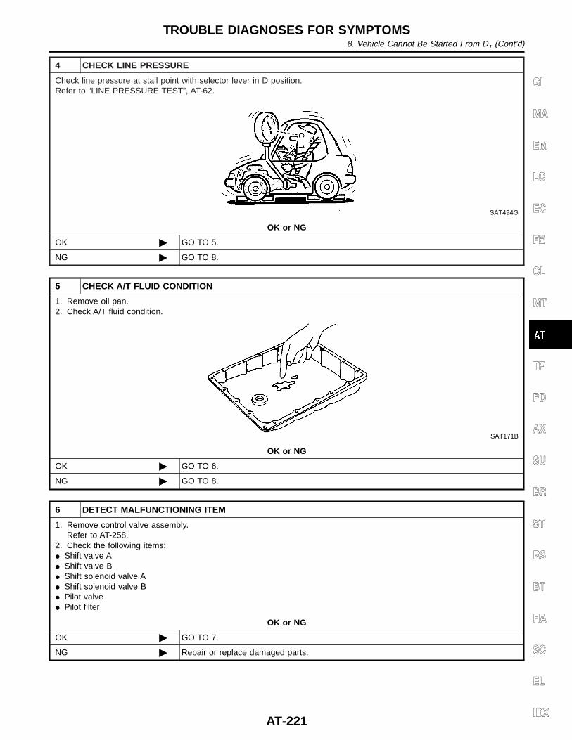
4 CHECK LINE PRESSURE
Check line pressure at stall point with selector lever in D position.Refer to “LINE PRESSURE TEST”, AT-62.
SAT494G
OK or NG
OK © GO TO 5.
NG © GO TO 8.
5 CHECK A/T FLUID CONDITION
1. Remove oil pan.2. Check A/T fluid condition.
SAT171B
OK or NG
OK © GO TO 6.
NG © GO TO 8.
6 DETECT MALFUNCTIONING ITEM
1. Remove control valve assembly.Refer to AT-258.
2. Check the following items:I Shift valve AI Shift valve BI Shift solenoid valve AI Shift solenoid valve BI Pilot valveI Pilot filter
OK or NG
OK © GO TO 7.
NG © Repair or replace damaged parts.
GI
MA
EM
LC
EC
FE
CL
MT
TF
PD
AX
SU
BR
ST
RS
BT
HA
SC
EL
IDX
TROUBLE DIAGNOSES FOR SYMPTOMS8. Vehicle Cannot Be Started From D1 (Cont’d)
AT-221
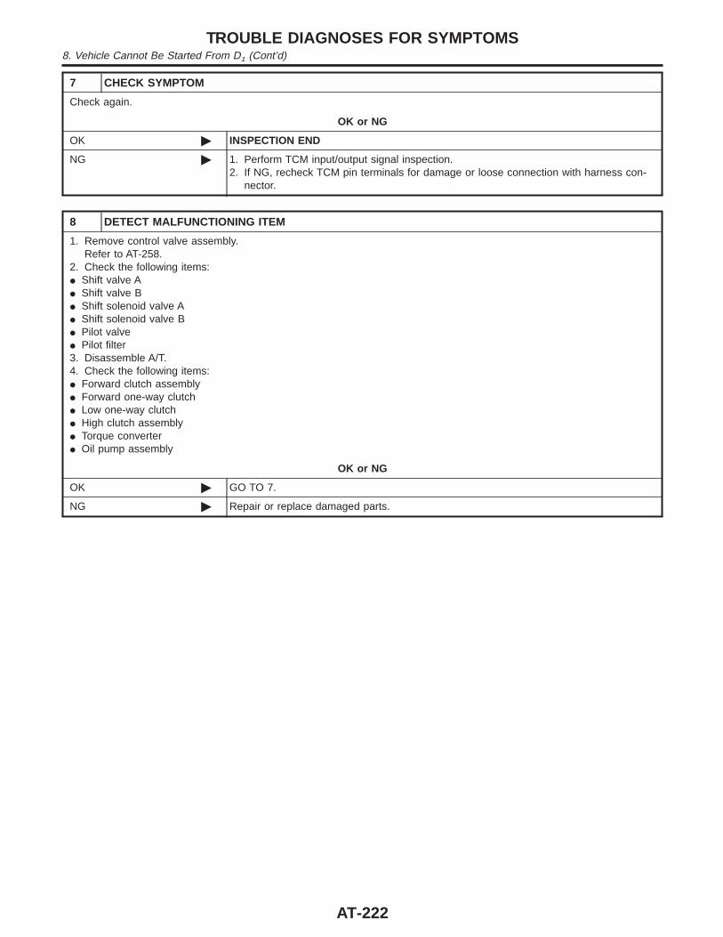
7 CHECK SYMPTOM
Check again.
OK or NG
OK © INSPECTION END
NG © 1. Perform TCM input/output signal inspection.2. If NG, recheck TCM pin terminals for damage or loose connection with harness con-
nector.
8 DETECT MALFUNCTIONING ITEM
1. Remove control valve assembly.Refer to AT-258.
2. Check the following items:I Shift valve AI Shift valve BI Shift solenoid valve AI Shift solenoid valve BI Pilot valveI Pilot filter3. Disassemble A/T.4. Check the following items:I Forward clutch assemblyI Forward one-way clutchI Low one-way clutchI High clutch assemblyI Torque converterI Oil pump assembly
OK or NG
OK © GO TO 7.
NG © Repair or replace damaged parts.
TROUBLE DIAGNOSES FOR SYMPTOMS8. Vehicle Cannot Be Started From D1 (Cont’d)
AT-222
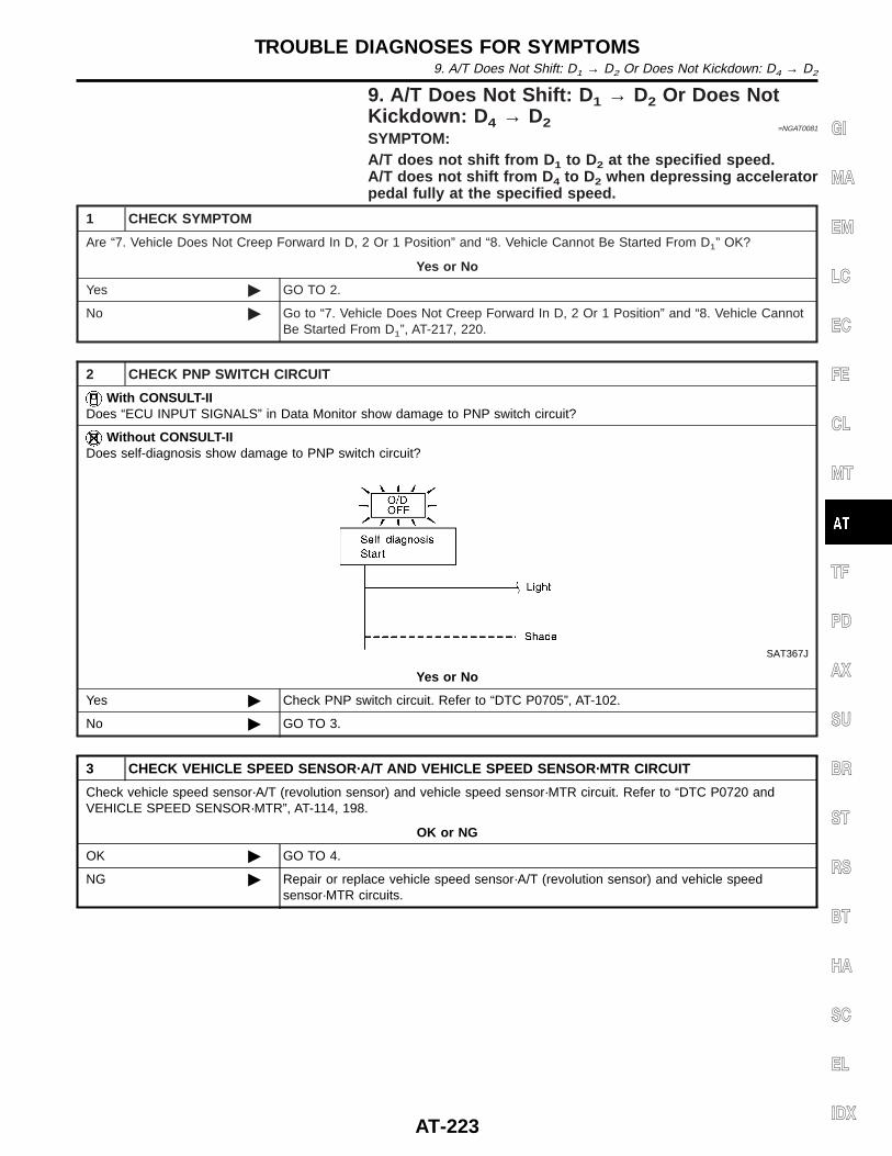
9. A/T Does Not Shift: D 1 → D2 Or Does NotKickdown: D 4 → D2 =NGAT0081
SYMPTOM:A/T does not shift from D 1 to D2 at the specified speed.A/T does not shift from D 4 to D2 when depressing acceleratorpedal fully at the specified speed.
1 CHECK SYMPTOM
Are “7. Vehicle Does Not Creep Forward In D, 2 Or 1 Position” and “8. Vehicle Cannot Be Started From D1” OK?
Yes or No
Yes © GO TO 2.
No © Go to “7. Vehicle Does Not Creep Forward In D, 2 Or 1 Position” and “8. Vehicle CannotBe Started From D1”, AT-217, 220.
2 CHECK PNP SWITCH CIRCUIT
With CONSULT-IIDoes “ECU INPUT SIGNALS” in Data Monitor show damage to PNP switch circuit?
Without CONSULT-IIDoes self-diagnosis show damage to PNP switch circuit?
SAT367J
Yes or No
Yes © Check PNP switch circuit. Refer to “DTC P0705”, AT-102.
No © GO TO 3.
3 CHECK VEHICLE SPEED SENSOR·A/T AND VEHICLE SPEED SENSOR·MTR CIRCUIT
Check vehicle speed sensor·A/T (revolution sensor) and vehicle speed sensor·MTR circuit. Refer to “DTC P0720 andVEHICLE SPEED SENSOR·MTR”, AT-114, 198.
OK or NG
OK © GO TO 4.
NG © Repair or replace vehicle speed sensor·A/T (revolution sensor) and vehicle speedsensor·MTR circuits.
GI
MA
EM
LC
EC
FE
CL
MT
TF
PD
AX
SU
BR
ST
RS
BT
HA
SC
EL
IDX
TROUBLE DIAGNOSES FOR SYMPTOMS9. A/T Does Not Shift: D1 → D2 Or Does Not Kickdown: D4 → D2
AT-223
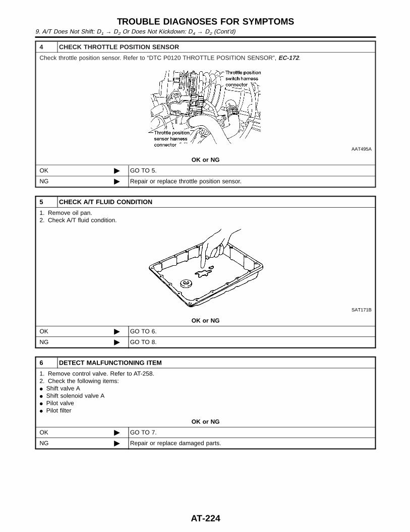
4 CHECK THROTTLE POSITION SENSOR
Check throttle position sensor. Refer to “DTC P0120 THROTTLE POSITION SENSOR”, EC-172.
AAT495A
OK or NG
OK © GO TO 5.
NG © Repair or replace throttle position sensor.
5 CHECK A/T FLUID CONDITION
1. Remove oil pan.2. Check A/T fluid condition.
SAT171B
OK or NG
OK © GO TO 6.
NG © GO TO 8.
6 DETECT MALFUNCTIONING ITEM
1. Remove control valve. Refer to AT-258.2. Check the following items:I Shift valve AI Shift solenoid valve AI Pilot valveI Pilot filter
OK or NG
OK © GO TO 7.
NG © Repair or replace damaged parts.
TROUBLE DIAGNOSES FOR SYMPTOMS9. A/T Does Not Shift: D1 → D2 Or Does Not Kickdown: D4 → D2 (Cont’d)
AT-224
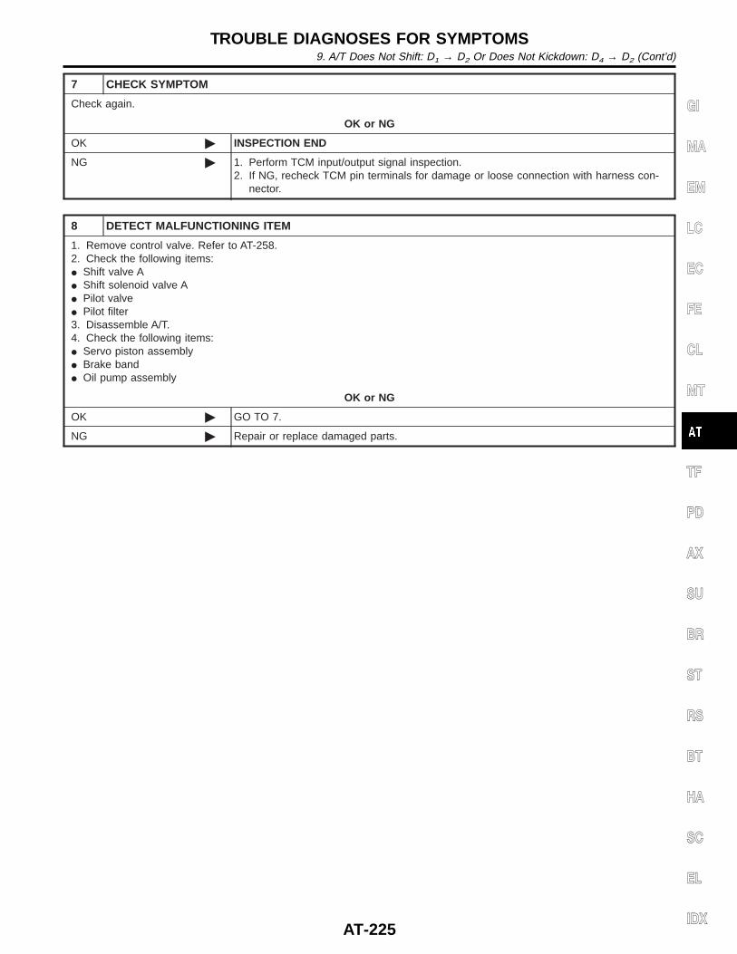
7 CHECK SYMPTOM
Check again.
OK or NG
OK © INSPECTION END
NG © 1. Perform TCM input/output signal inspection.2. If NG, recheck TCM pin terminals for damage or loose connection with harness con-
nector.
8 DETECT MALFUNCTIONING ITEM
1. Remove control valve. Refer to AT-258.2. Check the following items:I Shift valve AI Shift solenoid valve AI Pilot valveI Pilot filter3. Disassemble A/T.4. Check the following items:I Servo piston assemblyI Brake bandI Oil pump assembly
OK or NG
OK © GO TO 7.
NG © Repair or replace damaged parts.
GI
MA
EM
LC
EC
FE
CL
MT
TF
PD
AX
SU
BR
ST
RS
BT
HA
SC
EL
IDX
TROUBLE DIAGNOSES FOR SYMPTOMS9. A/T Does Not Shift: D1 → D2 Or Does Not Kickdown: D4 → D2 (Cont’d)
AT-225
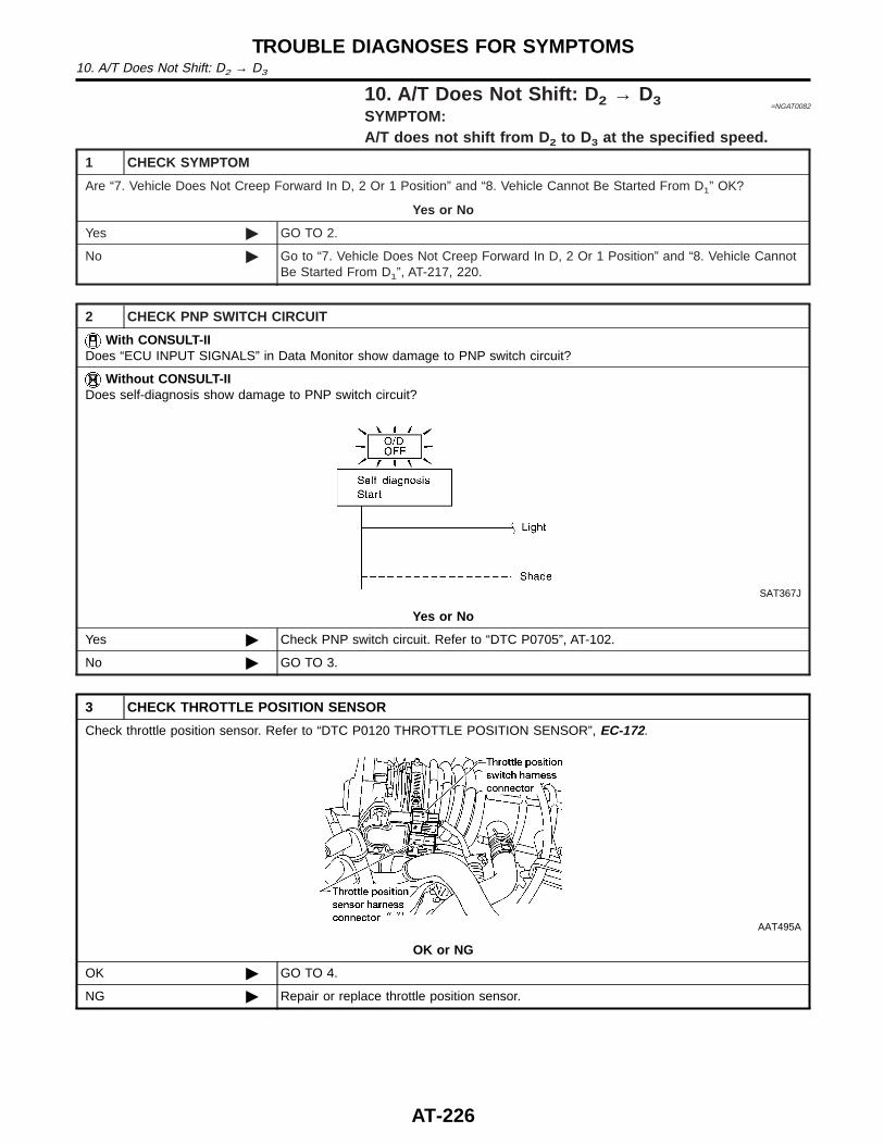
10. A/T Does Not Shift: D 2 → D3 =NGAT0082
SYMPTOM:A/T does not shift from D 2 to D3 at the specified speed.
1 CHECK SYMPTOM
Are “7. Vehicle Does Not Creep Forward In D, 2 Or 1 Position” and “8. Vehicle Cannot Be Started From D1” OK?
Yes or No
Yes © GO TO 2.
No © Go to “7. Vehicle Does Not Creep Forward In D, 2 Or 1 Position” and “8. Vehicle CannotBe Started From D1”, AT-217, 220.
2 CHECK PNP SWITCH CIRCUIT
With CONSULT-IIDoes “ECU INPUT SIGNALS” in Data Monitor show damage to PNP switch circuit?
Without CONSULT-IIDoes self-diagnosis show damage to PNP switch circuit?
SAT367J
Yes or No
Yes © Check PNP switch circuit. Refer to “DTC P0705”, AT-102.
No © GO TO 3.
3 CHECK THROTTLE POSITION SENSOR
Check throttle position sensor. Refer to “DTC P0120 THROTTLE POSITION SENSOR”, EC-172.
AAT495A
OK or NG
OK © GO TO 4.
NG © Repair or replace throttle position sensor.
TROUBLE DIAGNOSES FOR SYMPTOMS10. A/T Does Not Shift: D2 → D3
AT-226
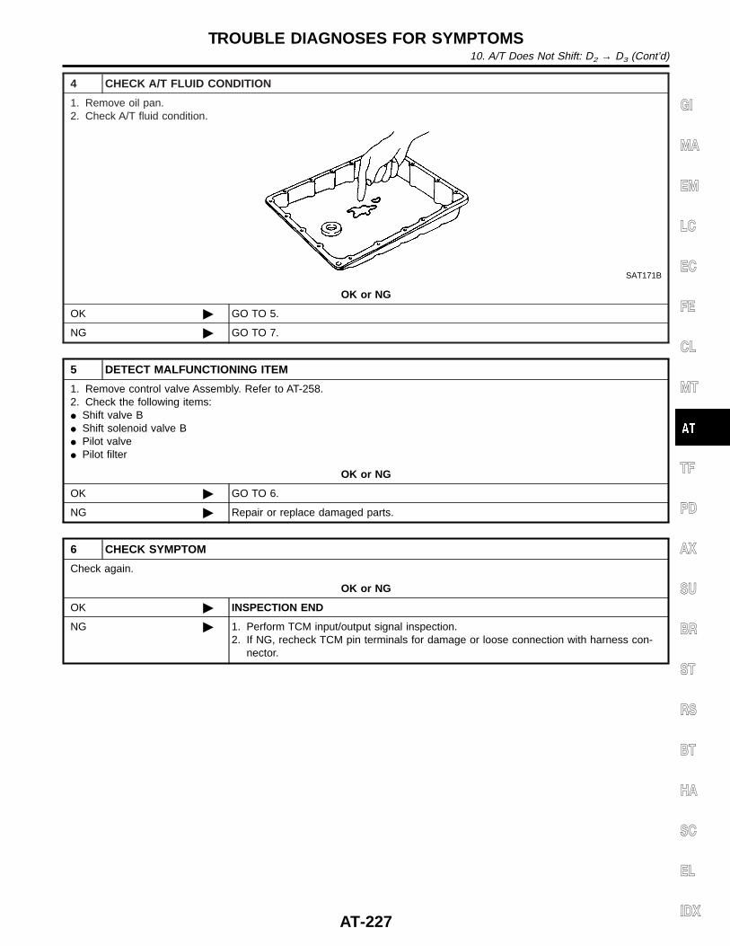
4 CHECK A/T FLUID CONDITION
1. Remove oil pan.2. Check A/T fluid condition.
SAT171B
OK or NG
OK © GO TO 5.
NG © GO TO 7.
5 DETECT MALFUNCTIONING ITEM
1. Remove control valve Assembly. Refer to AT-258.2. Check the following items:I Shift valve BI Shift solenoid valve BI Pilot valveI Pilot filter
OK or NG
OK © GO TO 6.
NG © Repair or replace damaged parts.
6 CHECK SYMPTOM
Check again.
OK or NG
OK © INSPECTION END
NG © 1. Perform TCM input/output signal inspection.2. If NG, recheck TCM pin terminals for damage or loose connection with harness con-
nector.
GI
MA
EM
LC
EC
FE
CL
MT
TF
PD
AX
SU
BR
ST
RS
BT
HA
SC
EL
IDX
TROUBLE DIAGNOSES FOR SYMPTOMS10. A/T Does Not Shift: D2 → D3 (Cont’d)
AT-227
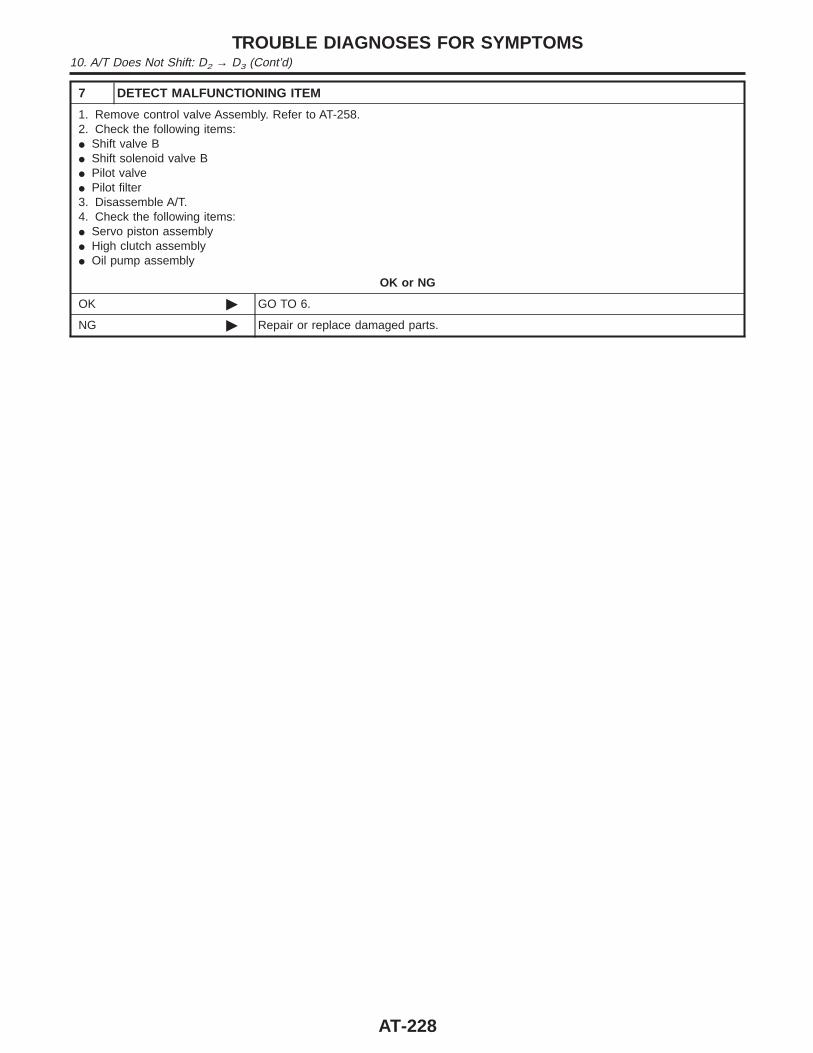
7 DETECT MALFUNCTIONING ITEM
1. Remove control valve Assembly. Refer to AT-258.2. Check the following items:I Shift valve BI Shift solenoid valve BI Pilot valveI Pilot filter3. Disassemble A/T.4. Check the following items:I Servo piston assemblyI High clutch assemblyI Oil pump assembly
OK or NG
OK © GO TO 6.
NG © Repair or replace damaged parts.
TROUBLE DIAGNOSES FOR SYMPTOMS10. A/T Does Not Shift: D2 → D3 (Cont’d)
AT-228
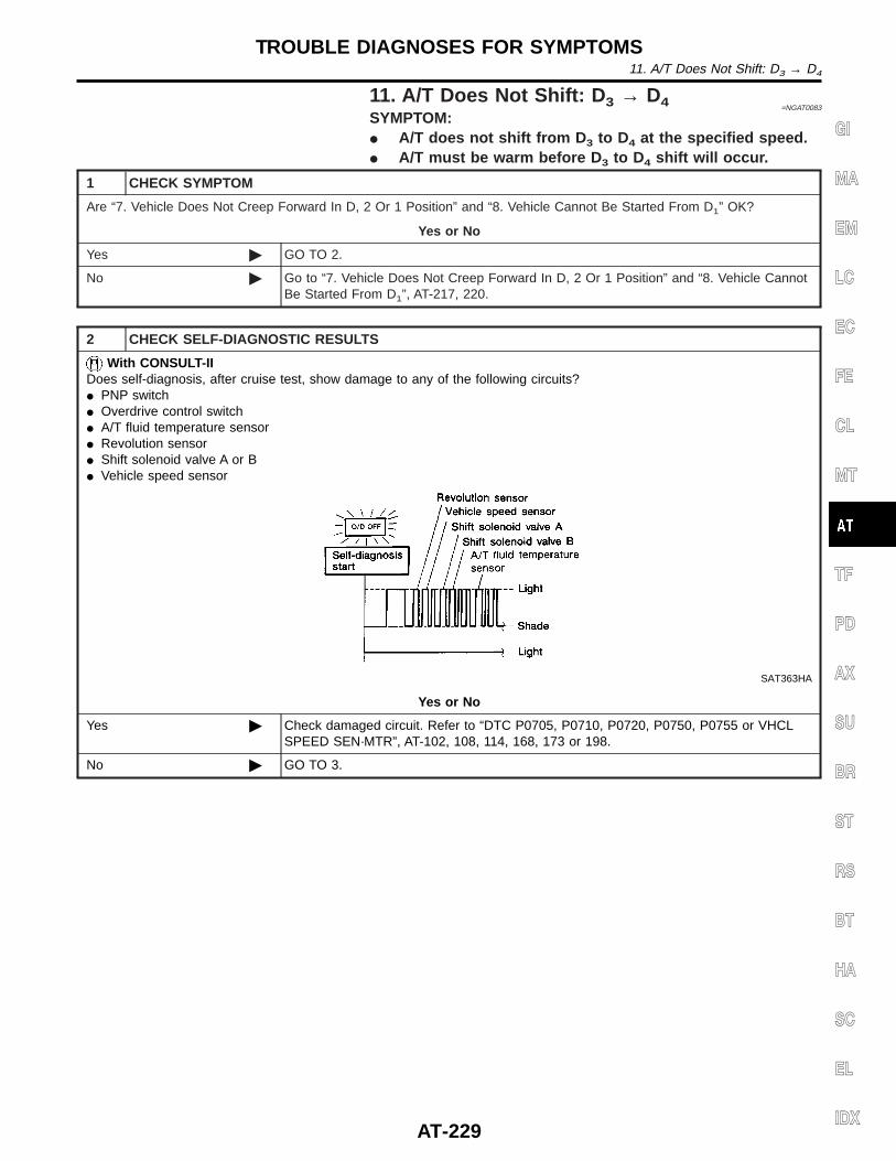
11. A/T Does Not Shift: D 3 → D4 =NGAT0083
SYMPTOM:I A/T does not shift from D 3 to D4 at the specified speed.I A/T must be warm before D 3 to D4 shift will occur.
1 CHECK SYMPTOM
Are “7. Vehicle Does Not Creep Forward In D, 2 Or 1 Position” and “8. Vehicle Cannot Be Started From D1” OK?
Yes or No
Yes © GO TO 2.
No © Go to “7. Vehicle Does Not Creep Forward In D, 2 Or 1 Position” and “8. Vehicle CannotBe Started From D1”, AT-217, 220.
2 CHECK SELF-DIAGNOSTIC RESULTS
With CONSULT-IIDoes self-diagnosis, after cruise test, show damage to any of the following circuits?I PNP switchI Overdrive control switchI A/T fluid temperature sensorI Revolution sensorI Shift solenoid valve A or BI Vehicle speed sensor
SAT363HA
Yes or No
Yes © Check damaged circuit. Refer to “DTC P0705, P0710, P0720, P0750, P0755 or VHCLSPEED SEN·MTR”, AT-102, 108, 114, 168, 173 or 198.
No © GO TO 3.
GI
MA
EM
LC
EC
FE
CL
MT
TF
PD
AX
SU
BR
ST
RS
BT
HA
SC
EL
IDX
TROUBLE DIAGNOSES FOR SYMPTOMS11. A/T Does Not Shift: D3 → D4
AT-229
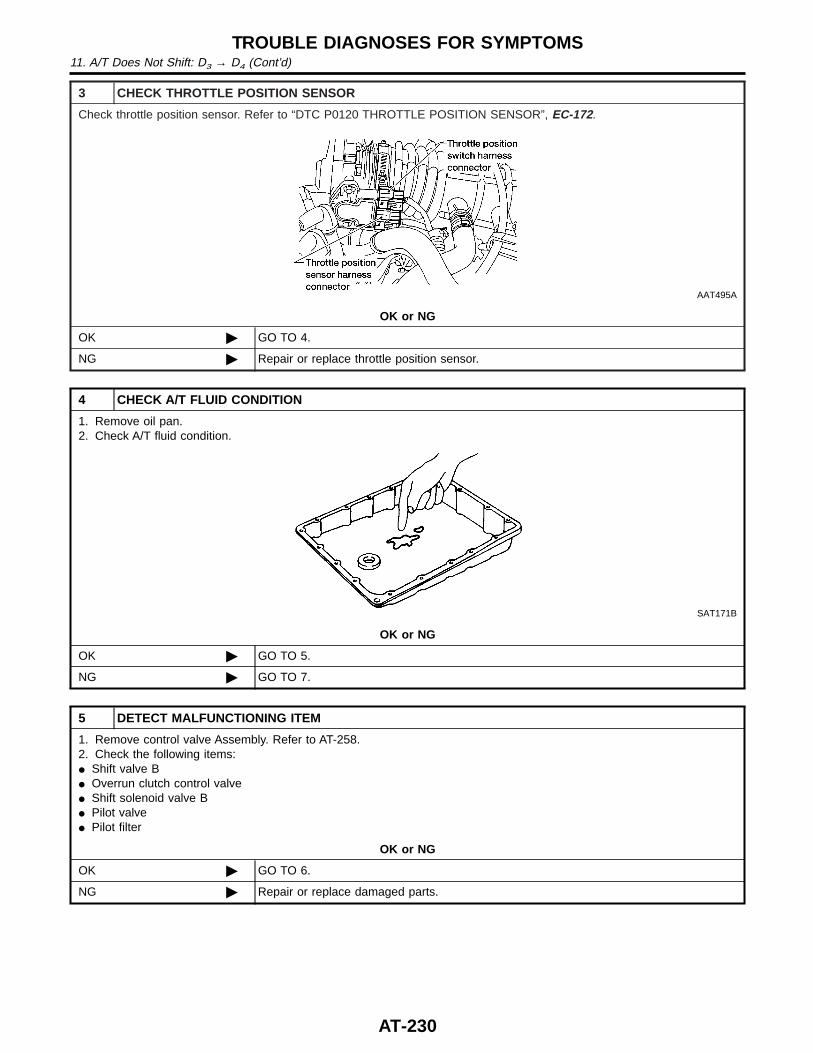
3 CHECK THROTTLE POSITION SENSOR
Check throttle position sensor. Refer to “DTC P0120 THROTTLE POSITION SENSOR”, EC-172.
AAT495A
OK or NG
OK © GO TO 4.
NG © Repair or replace throttle position sensor.
4 CHECK A/T FLUID CONDITION
1. Remove oil pan.2. Check A/T fluid condition.
SAT171B
OK or NG
OK © GO TO 5.
NG © GO TO 7.
5 DETECT MALFUNCTIONING ITEM
1. Remove control valve Assembly. Refer to AT-258.2. Check the following items:I Shift valve BI Overrun clutch control valveI Shift solenoid valve BI Pilot valveI Pilot filter
OK or NG
OK © GO TO 6.
NG © Repair or replace damaged parts.
TROUBLE DIAGNOSES FOR SYMPTOMS11. A/T Does Not Shift: D3 → D4 (Cont’d)
AT-230

6 CHECK SYMPTOM
Check again.
OK or NG
OK © INSPECTION END
NG © 1. Perform TCM input/output signal inspection.2. If NG, recheck TCM pin terminals for damage or loose connection with harness con-
nector.
7 DETECT MALFUNCTIONING ITEM
1. Remove control valve Assembly. Refer to AT-258.2. Check the following items:I Shift valve BI Overrun clutch control valveI Shift solenoid valve BI Pilot valveI Pilot filter3. Disassemble A/T.4. Check the following items:I Servo piston assemblyI Brake bandI Torque converterI Oil pump assembly
OK or NG
OK © GO TO 6.
NG © Repair or replace damaged parts.
GI
MA
EM
LC
EC
FE
CL
MT
TF
PD
AX
SU
BR
ST
RS
BT
HA
SC
EL
IDX
TROUBLE DIAGNOSES FOR SYMPTOMS11. A/T Does Not Shift: D3 → D4 (Cont’d)
AT-231
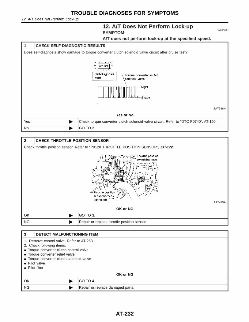
12. A/T Does Not Perform Lock-up=NGAT0084
SYMPTOM:A/T does not perform lock-up at the specified speed.
1 CHECK SELF-DIAGNOSTIC RESULTS
Does self-diagnosis show damage to torque converter clutch solenoid valve circuit after cruise test?
SAT346H
Yes or No
Yes © Check torque converter clutch solenoid valve circuit. Refer to “DTC P0740”, AT-150.
No © GO TO 2.
2 CHECK THROTTLE POSITION SENSOR
Check throttle position sensor. Refer to “P0120 THROTTLE POSITION SENSOR”, EC-172.
AAT495A
OK or NG
OK © GO TO 3.
NG © Repair or replace throttle position sensor.
3 DETECT MALFUNCTIONING ITEM
1. Remove control valve. Refer to AT-258.2. Check following items:I Torque converter clutch control valveI Torque converter relief valveI Torque converter clutch solenoid valveI Pilot valveI Pilot filter
OK or NG
OK © GO TO 4.
NG © Repair or replace damaged parts.
TROUBLE DIAGNOSES FOR SYMPTOMS12. A/T Does Not Perform Lock-up
AT-232
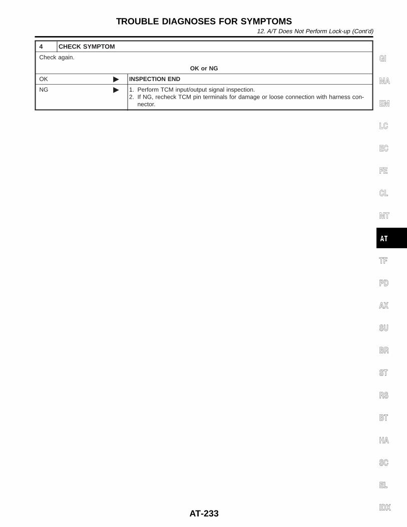
4 CHECK SYMPTOM
Check again.
OK or NG
OK © INSPECTION END
NG © 1. Perform TCM input/output signal inspection.2. If NG, recheck TCM pin terminals for damage or loose connection with harness con-
nector.
GI
MA
EM
LC
EC
FE
CL
MT
TF
PD
AX
SU
BR
ST
RS
BT
HA
SC
EL
IDX
TROUBLE DIAGNOSES FOR SYMPTOMS12. A/T Does Not Perform Lock-up (Cont’d)
AT-233
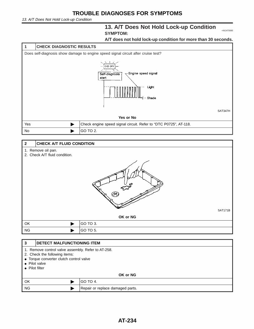
13. A/T Does Not Hold Lock-up Condition=NGAT0085
SYMPTOM:A/T does not hold lock-up condition for more than 30 seconds.
1 CHECK DIAGNOSTIC RESULTS
Does self-diagnosis show damage to engine speed signal circuit after cruise test?
SAT347H
Yes or No
Yes © Check engine speed signal circuit. Refer to “DTC P0725”, AT-118.
No © GO TO 2.
2 CHECK A/T FLUID CONDITION
1. Remove oil pan.2. Check A/T fluid condition.
SAT171B
OK or NG
OK © GO TO 3.
NG © GO TO 5.
3 DETECT MALFUNCTIONING ITEM
1. Remove control valve assembly. Refer to AT-258.2. Check the following items:I Torque converter clutch control valveI Pilot valveI Pilot filter
OK or NG
OK © GO TO 4.
NG © Repair or replace damaged parts.
TROUBLE DIAGNOSES FOR SYMPTOMS13. A/T Does Not Hold Lock-up Condition
AT-234
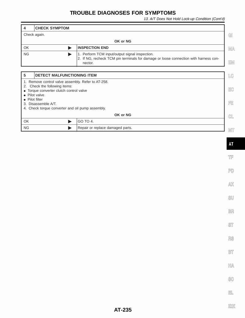
4 CHECK SYMPTOM
Check again.
OK or NG
OK © INSPECTION END
NG © 1. Perform TCM input/output signal inspection.2. If NG, recheck TCM pin terminals for damage or loose connection with harness con-
nector.
5 DETECT MALFUNCTIONING ITEM
1. Remove control valve assembly. Refer to AT-258.2. Check the following items:I Torque converter clutch control valveI Pilot valveI Pilot filter3. Disassemble A/T.4. Check torque converter and oil pump assembly.
OK or NG
OK © GO TO 4.
NG © Repair or replace damaged parts.
GI
MA
EM
LC
EC
FE
CL
MT
TF
PD
AX
SU
BR
ST
RS
BT
HA
SC
EL
IDX
TROUBLE DIAGNOSES FOR SYMPTOMS13. A/T Does Not Hold Lock-up Condition (Cont’d)
AT-235

14. Lock-up Is Not Released=NGAT0086
SYMPTOM:Lock-up is not released when accelerator pedal is released.
1 CHECK THROTTLE POSITION SWITCH CIRCUIT
With CONSULT-IIDoes “ECU INPUT SIGNALS” in Data Monitor show damage to closed throttle position switch circuit?
Without CONSULT-IIDoes self-diagnosis show damage to closed throttle position switch circuit?
SAT367J
Yes or No
Yes © Check closed throttle position switch circuit. Refer to “DTC P1705”, AT-179.
No © GO TO 2.
2 CHECK SYMPTOM
Check again.
OK or NG
OK © INSPECTION END
NG © 1. Perform TCM input/output signal inspection.2. If NG, recheck TCM pin terminals for damage or loose connection with harness con-
nector.
TROUBLE DIAGNOSES FOR SYMPTOMS14. Lock-up Is Not Released
AT-236
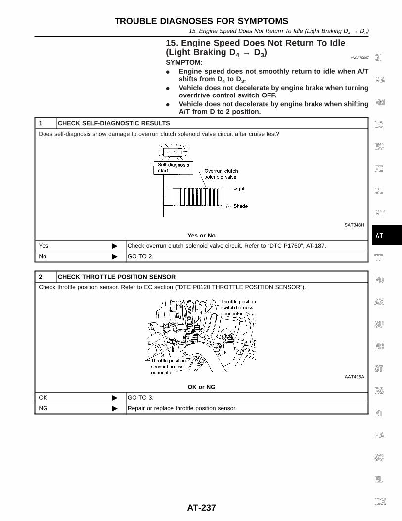
15. Engine Speed Does Not Return To Idle(Light Braking D 4 → D3)
=NGAT0087
SYMPTOM:I Engine speed does not smoothly return to idle when A/T
shifts from D 4 to D3.I Vehicle does not decelerate by engine brake when turning
overdrive control switch OFF.I Vehicle does not decelerate by engine brake when shifting
A/T from D to 2 position.
1 CHECK SELF-DIAGNOSTIC RESULTS
Does self-diagnosis show damage to overrun clutch solenoid valve circuit after cruise test?
SAT348H
Yes or No
Yes © Check overrun clutch solenoid valve circuit. Refer to “DTC P1760”, AT-187.
No © GO TO 2.
2 CHECK THROTTLE POSITION SENSOR
Check throttle position sensor. Refer to EC section (“DTC P0120 THROTTLE POSITION SENSOR”).
AAT495A
OK or NG
OK © GO TO 3.
NG © Repair or replace throttle position sensor.
GI
MA
EM
LC
EC
FE
CL
MT
TF
PD
AX
SU
BR
ST
RS
BT
HA
SC
EL
IDX
TROUBLE DIAGNOSES FOR SYMPTOMS15. Engine Speed Does Not Return To Idle (Light Braking D4 → D3)
AT-237
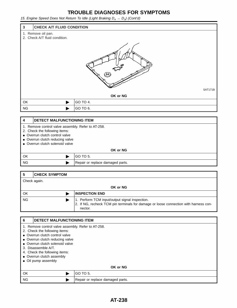
3 CHECK A/T FLUID CONDITION
1. Remove oil pan.2. Check A/T fluid condition.
SAT171B
OK or NG
OK © GO TO 4.
NG © GO TO 6.
4 DETECT MALFUNCTIONING ITEM
1. Remove control valve assembly. Refer to AT-258.2. Check the following items:I Overrun clutch control valveI Overrun clutch reducing valveI Overrun clutch solenoid valve
OK or NG
OK © GO TO 5.
NG © Repair or replace damaged parts.
5 CHECK SYMPTOM
Check again.
OK or NG
OK © INSPECTION END
NG © 1. Perform TCM input/output signal inspection.2. If NG, recheck TCM pin terminals for damage or loose connection with harness con-
nector.
6 DETECT MALFUNCTIONING ITEM
1. Remove control valve assembly. Refer to AT-258.2. Check the following items:I Overrun clutch control valveI Overrun clutch reducing valveI Overrun clutch solenoid valve3. Disassemble A/T.4. Check the following items:I Overrun clutch assemblyI Oil pump assembly
OK or NG
OK © GO TO 5.
NG © Repair or replace damaged parts.
TROUBLE DIAGNOSES FOR SYMPTOMS15. Engine Speed Does Not Return To Idle (Light Braking D4 → D3) (Cont’d)
AT-238
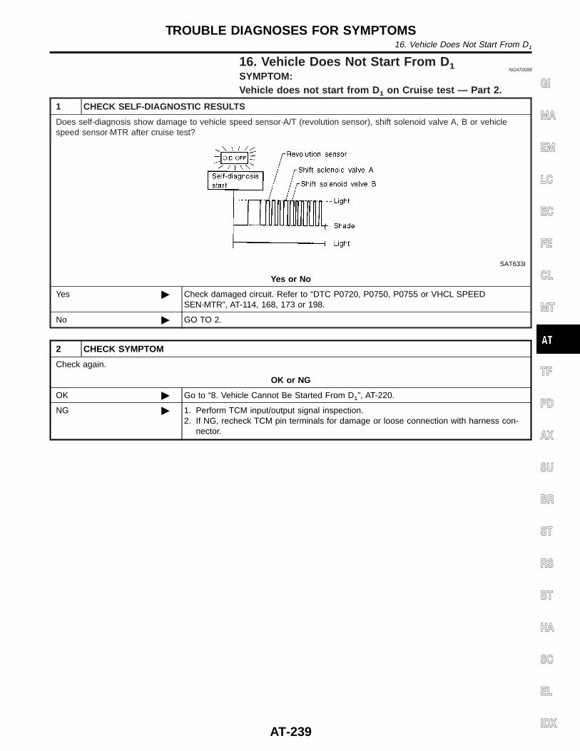
16. Vehicle Does Not Start From D 1 NGAT0088
SYMPTOM:Vehicle does not start from D 1 on Cruise test — Part 2.
1 CHECK SELF-DIAGNOSTIC RESULTS
Does self-diagnosis show damage to vehicle speed sensor·A/T (revolution sensor), shift solenoid valve A, B or vehiclespeed sensor·MTR after cruise test?
SAT633I
Yes or No
Yes © Check damaged circuit. Refer to “DTC P0720, P0750, P0755 or VHCL SPEEDSEN·MTR”, AT-114, 168, 173 or 198.
No © GO TO 2.
2 CHECK SYMPTOM
Check again.
OK or NG
OK © Go to “8. Vehicle Cannot Be Started From D1”, AT-220.
NG © 1. Perform TCM input/output signal inspection.2. If NG, recheck TCM pin terminals for damage or loose connection with harness con-
nector.
GI
MA
EM
LC
EC
FE
CL
MT
TF
PD
AX
SU
BR
ST
RS
BT
HA
SC
EL
IDX
TROUBLE DIAGNOSES FOR SYMPTOMS16. Vehicle Does Not Start From D1
AT-239
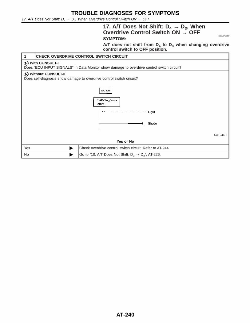
17. A/T Does Not Shift: D 4 → D3, WhenOverdrive Control Switch ON → OFF
=NGAT0089
SYMPTOM:A/T does not shift from D 4 to D3 when changing overdrivecontrol switch to OFF position.
1 CHECK OVERDRIVE CONTROL SWITCH CIRCUIT
With CONSULT-IIDoes “ECU INPUT SIGNALS” in Data Monitor show damage to overdrive control switch circuit?
Without CONSULT-IIDoes self-diagnosis show damage to overdrive control switch circuit?
SAT344H
Yes or No
Yes © Check overdrive control switch circuit. Refer to AT-244.
No © Go to “10. A/T Does Not Shift: D2 , D3”, AT-226.
TROUBLE DIAGNOSES FOR SYMPTOMS17. A/T Does Not Shift: D4 → D3, When Overdrive Control Switch ON → OFF
AT-240

18. A/T Does Not Shift: D 3 → 22, When SelectorLever D → 2 Position
=NGAT0090
SYMPTOM:A/T does not shift from D 3 to 22 when changing selector leverfrom D to 2 position.
1 CHECK PNP SWITCH CIRCUIT
With CONSULT-IIDoes “ECU INPUT SIGNALS” in Data Monitor show damage to PNP switch circuit?
Without CONSULT-IIDoes self-diagnosis show damage to PNP switch circuit?
SAT367J
Yes or No
Yes © Check PNP switch circuit. Refer to “DTC P0705”, AT-102.
No © Go to “9. A/T Does Not Shift: D1 , D2 Or Does Not Kickdown: D4 , D2”, AT-223.
GI
MA
EM
LC
EC
FE
CL
MT
TF
PD
AX
SU
BR
ST
RS
BT
HA
SC
EL
IDX
TROUBLE DIAGNOSES FOR SYMPTOMS18. A/T Does Not Shift: D3 → 22, When Selector Lever D → 2 Position
AT-241
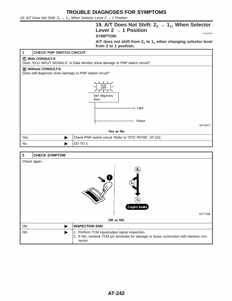
19. A/T Does Not Shift: 2 2 → 11, When SelectorLever 2 → 1 Position
=NGAT0091
SYMPTOM:A/T does not shift from 2 2 to 11 when changing selector leverfrom 2 to 1 position.
1 CHECK PNP SWITCH CIRCUIT
With CONSULT-IIDoes “ECU INPUT SIGNALS” in Data Monitor show damage to PNP switch circuit?
Without CONSULT-IIDoes self-diagnosis show damage to PNP switch circuit?
SAT367J
Yes or No
Yes © Check PNP switch circuit. Refer to “DTC P0705”, AT-102.
No © GO TO 2.
2 CHECK SYMPTOM
Check again.
SAT778B
OK or NG
OK © INSPECTION END
NG © 1. Perform TCM input/output signal inspection.2. If NG, recheck TCM pin terminals for damage or loose connection with harness con-
nector.
TROUBLE DIAGNOSES FOR SYMPTOMS19. A/T Does Not Shift: 22 → 11, When Selector Lever 2 → 1 Position
AT-242
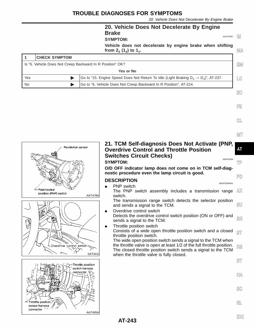
20. Vehicle Does Not Decelerate By EngineBrake
NGAT0092
SYMPTOM:Vehicle does not decelerate by engine brake when shiftingfrom 2 2 (12) to 11.
1 CHECK SYMPTOM
Is “6. Vehicle Does Not Creep Backward In R Position” OK?
Yes or No
Yes © Go to “15. Engine Speed Does Not Return To Idle (Light Braking D4 , D3)”, AT-237.
No © Go to “6. Vehicle Does Not Creep Backward In R Position”, AT-214.
AAT478A
SAT341I
AAT495A
21. TCM Self-diagnosis Does Not Activate (PNP,Overdrive Control and Throttle PositionSwitches Circuit Checks)
NGAT0204
SYMPTOM:O/D OFF indicator lamp does not come on in TCM self-diag-nostic procedure even the lamp circuit is good.
DESCRIPTIONNGAT0204S01
I PNP switchThe PNP switch assembly includes a transmission rangeswitch.The transmission range switch detects the selector positionand sends a signal to the TCM.
I Overdrive control switchDetects the overdrive control switch position (ON or OFF) andsends a signal to the TCM.
I Throttle position switchConsists of a wide open throttle position switch and a closedthrottle position switch.The wide open position switch sends a signal to the TCM whenthe throttle valve is open at least 1/2 of the full throttle position.The closed throttle position switch sends a signal to the TCMwhen the throttle valve is fully closed.
GI
MA
EM
LC
EC
FE
CL
MT
TF
PD
AX
SU
BR
ST
RS
BT
HA
SC
EL
IDX
TROUBLE DIAGNOSES FOR SYMPTOMS20. Vehicle Does Not Decelerate By Engine Brake
AT-243
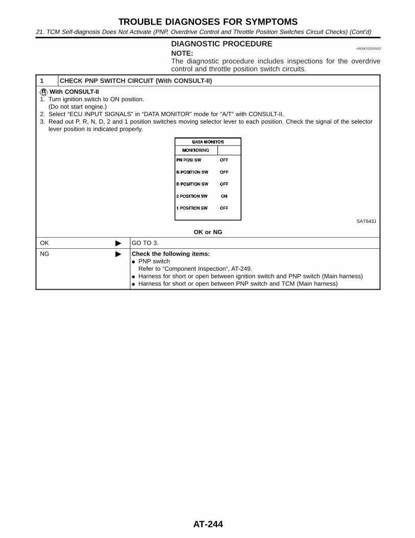
DIAGNOSTIC PROCEDURE=NGAT0204S03
NOTE:The diagnostic procedure includes inspections for the overdrivecontrol and throttle position switch circuits.
1 CHECK PNP SWITCH CIRCUIT (With CONSULT-II)
With CONSULT-II1. Turn ignition switch to ON position.
(Do not start engine.)2. Select “ECU INPUT SIGNALS” in “DATA MONITOR” mode for “A/T” with CONSULT-II.3. Read out P, R, N, D, 2 and 1 position switches moving selector lever to each position. Check the signal of the selector
lever position is indicated properly.
SAT643J
OK or NG
OK © GO TO 3.
NG © Check the following items:I PNP switch
Refer to “Component Inspection”, AT-249.I Harness for short or open between ignition switch and PNP switch (Main harness)I Harness for short or open between PNP switch and TCM (Main harness)
TROUBLE DIAGNOSES FOR SYMPTOMS21. TCM Self-diagnosis Does Not Activate (PNP, Overdrive Control and Throttle Position Switches Circuit Checks) (Cont’d)
AT-244
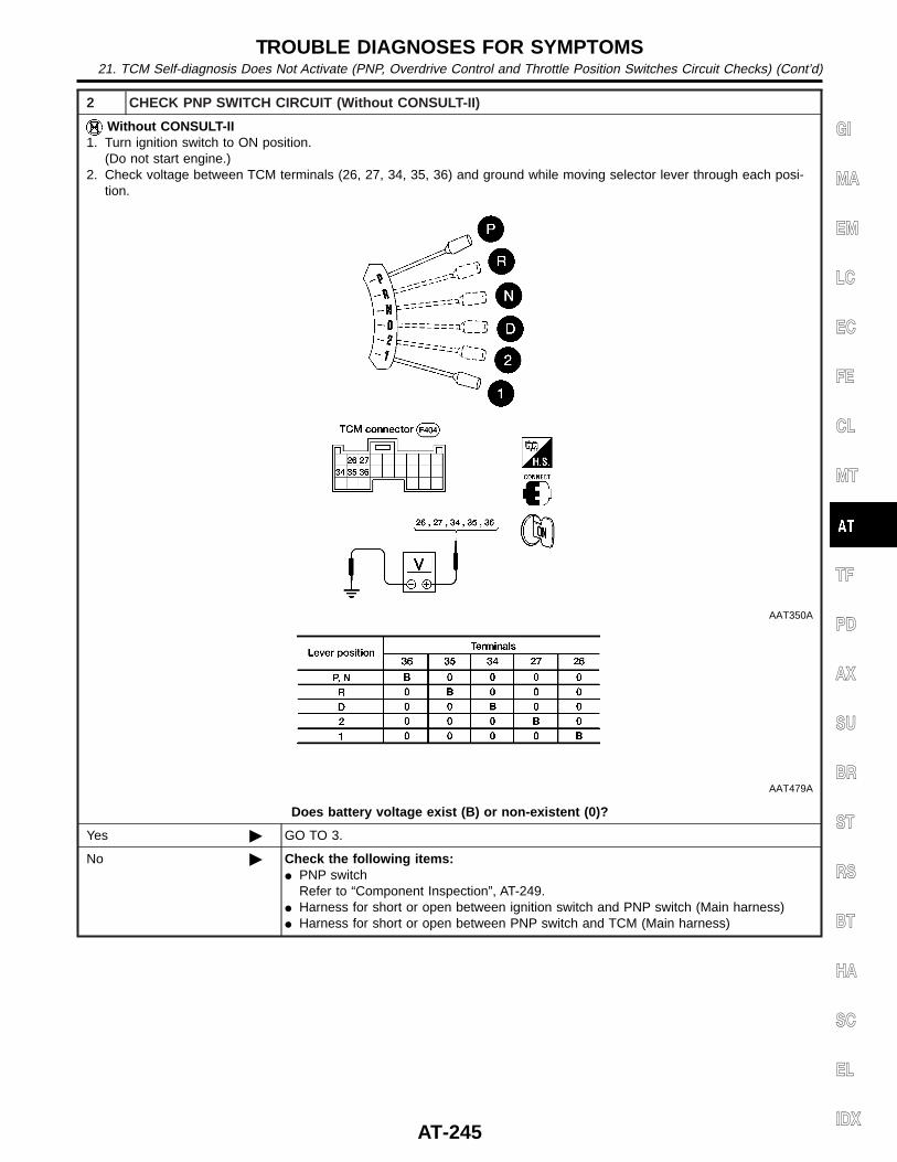
2 CHECK PNP SWITCH CIRCUIT (Without CONSULT-II)
Without CONSULT-II1. Turn ignition switch to ON position.
(Do not start engine.)2. Check voltage between TCM terminals (26, 27, 34, 35, 36) and ground while moving selector lever through each posi-
tion.
AAT350A
AAT479A
Does battery voltage exist (B) or non-existent (0)?
Yes © GO TO 3.
No © Check the following items:I PNP switch
Refer to “Component Inspection”, AT-249.I Harness for short or open between ignition switch and PNP switch (Main harness)I Harness for short or open between PNP switch and TCM (Main harness)
GI
MA
EM
LC
EC
FE
CL
MT
TF
PD
AX
SU
BR
ST
RS
BT
HA
SC
EL
IDX
TROUBLE DIAGNOSES FOR SYMPTOMS21. TCM Self-diagnosis Does Not Activate (PNP, Overdrive Control and Throttle Position Switches Circuit Checks) (Cont’d)
AT-245
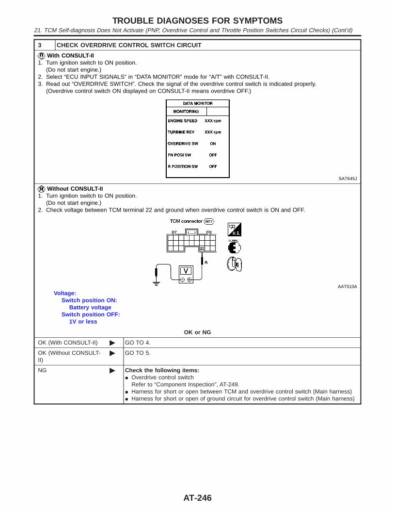
3 CHECK OVERDRIVE CONTROL SWITCH CIRCUIT
With CONSULT-II1. Turn ignition switch to ON position.
(Do not start engine.)2. Select “ECU INPUT SIGNALS” in “DATA MONITOR” mode for “A/T” with CONSULT-II.3. Read out “OVERDRIVE SWITCH”. Check the signal of the overdrive control switch is indicated properly.
(Overdrive control switch ON displayed on CONSULT-II means overdrive OFF.)
SAT645J
Without CONSULT-II1. Turn ignition switch to ON position.
(Do not start engine.)2. Check voltage between TCM terminal 22 and ground when overdrive control switch is ON and OFF.
AAT510A
Voltage:Switch position ON:
Battery voltageSwitch position OFF:
1V or less
OK or NG
OK (With CONSULT-II) © GO TO 4.
OK (Without CONSULT-II)
© GO TO 5.
NG © Check the following items:I Overdrive control switch
Refer to “Component Inspection”, AT-249.I Harness for short or open between TCM and overdrive control switch (Main harness)I Harness for short or open of ground circuit for overdrive control switch (Main harness)
TROUBLE DIAGNOSES FOR SYMPTOMS21. TCM Self-diagnosis Does Not Activate (PNP, Overdrive Control and Throttle Position Switches Circuit Checks) (Cont’d)
AT-246
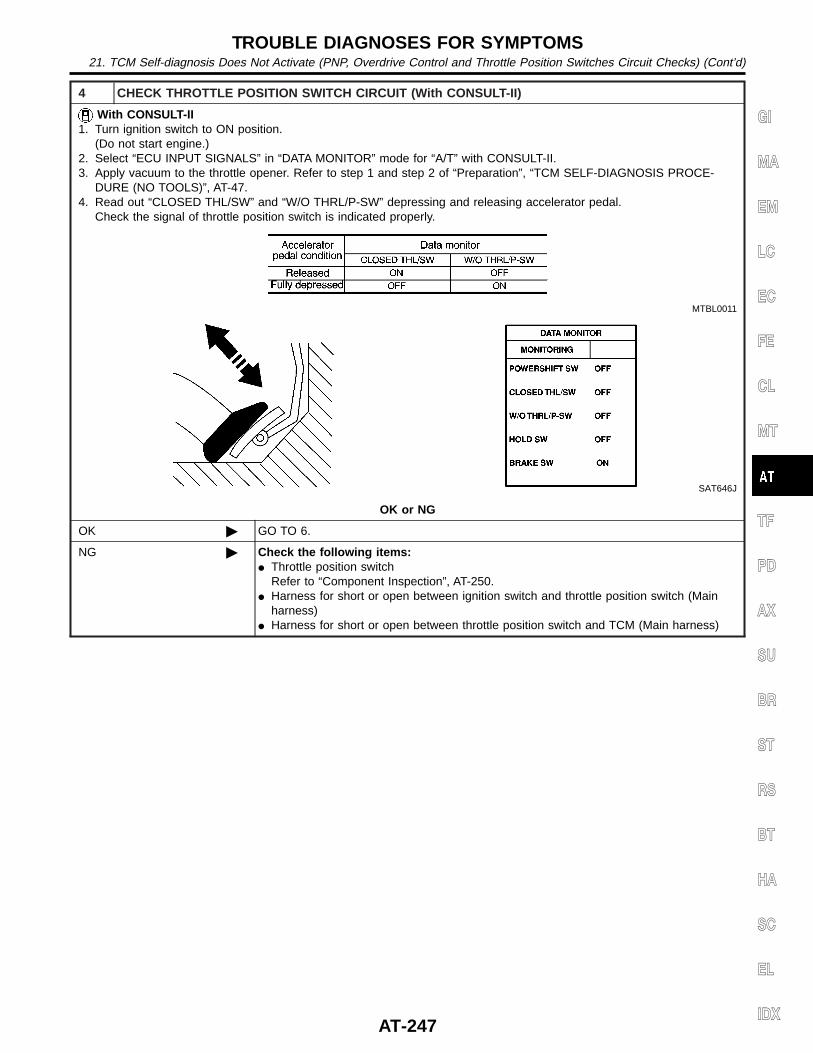
4 CHECK THROTTLE POSITION SWITCH CIRCUIT (With CONSULT-II)
With CONSULT-II1. Turn ignition switch to ON position.
(Do not start engine.)2. Select “ECU INPUT SIGNALS” in “DATA MONITOR” mode for “A/T” with CONSULT-II.3. Apply vacuum to the throttle opener. Refer to step 1 and step 2 of “Preparation”, “TCM SELF-DIAGNOSIS PROCE-
DURE (NO TOOLS)”, AT-47.4. Read out “CLOSED THL/SW” and “W/O THRL/P-SW” depressing and releasing accelerator pedal.
Check the signal of throttle position switch is indicated properly.
MTBL0011
SAT646J
OK or NG
OK © GO TO 6.
NG © Check the following items:I Throttle position switch
Refer to “Component Inspection”, AT-250.I Harness for short or open between ignition switch and throttle position switch (Main
harness)I Harness for short or open between throttle position switch and TCM (Main harness)
GI
MA
EM
LC
EC
FE
CL
MT
TF
PD
AX
SU
BR
ST
RS
BT
HA
SC
EL
IDX
TROUBLE DIAGNOSES FOR SYMPTOMS21. TCM Self-diagnosis Does Not Activate (PNP, Overdrive Control and Throttle Position Switches Circuit Checks) (Cont’d)
AT-247
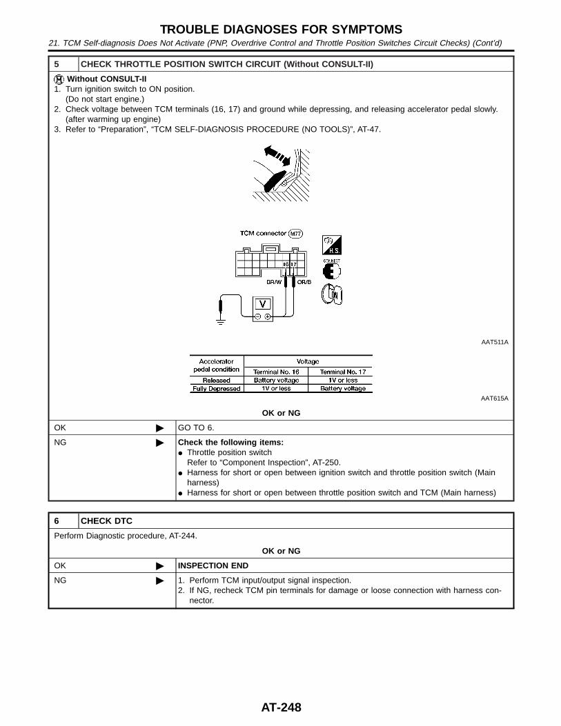
5 CHECK THROTTLE POSITION SWITCH CIRCUIT (Without CONSULT-II)
Without CONSULT-II1. Turn ignition switch to ON position.
(Do not start engine.)2. Check voltage between TCM terminals (16, 17) and ground while depressing, and releasing accelerator pedal slowly.
(after warming up engine)3. Refer to “Preparation”, “TCM SELF-DIAGNOSIS PROCEDURE (NO TOOLS)”, AT-47.
AAT511A
AAT615A
OK or NG
OK © GO TO 6.
NG © Check the following items:I Throttle position switch
Refer to “Component Inspection”, AT-250.I Harness for short or open between ignition switch and throttle position switch (Main
harness)I Harness for short or open between throttle position switch and TCM (Main harness)
6 CHECK DTC
Perform Diagnostic procedure, AT-244.
OK or NG
OK © INSPECTION END
NG © 1. Perform TCM input/output signal inspection.2. If NG, recheck TCM pin terminals for damage or loose connection with harness con-
nector.
TROUBLE DIAGNOSES FOR SYMPTOMS21. TCM Self-diagnosis Does Not Activate (PNP, Overdrive Control and Throttle Position Switches Circuit Checks) (Cont’d)
AT-248
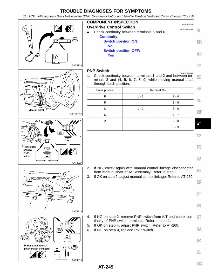
AAT512A
COMPONENT INSPECTIONNGAT0204S04
Overdrive Control SwitchNGAT0204S0401
I Check continuity between terminals 5 and 6.Continuity:
Switch position ON:No
Switch position OFF:Yes
SAT517GB
AAT482A
PNP SwitchNGAT0204S0402
1. Check continuity between terminals 1 and 2 and between ter-minals 3 and (4, 5, 6, 7, 8, 9) while moving manual shaftthrough each position.
Lever position Terminal No.
P 1 - 2 3 - 4
R 3 - 5
N 1 - 2 3 - 6
D 3 - 7
2 3 - 8
1 3 - 9
AAT551A
2. If NG, check again with manual control linkage disconnectedfrom manual shaft of A/T assembly. Refer to step 1.
3. If OK on step 2, adjust manual control linkage. Refer to AT-260.
AAT481A
4. If NG on step 2, remove PNP switch from A/T and check con-tinuity of PNP switch terminals. Refer to step 1.
5. If OK on step 4, adjust PNP switch. Refer to AT-260.6. If NG on step 4, replace PNP switch.
GI
MA
EM
LC
EC
FE
CL
MT
TF
PD
AX
SU
BR
ST
RS
BT
HA
SC
EL
IDX
TROUBLE DIAGNOSES FOR SYMPTOMS21. TCM Self-diagnosis Does Not Activate (PNP, Overdrive Control and Throttle Position Switches Circuit Checks) (Cont’d)
AT-249
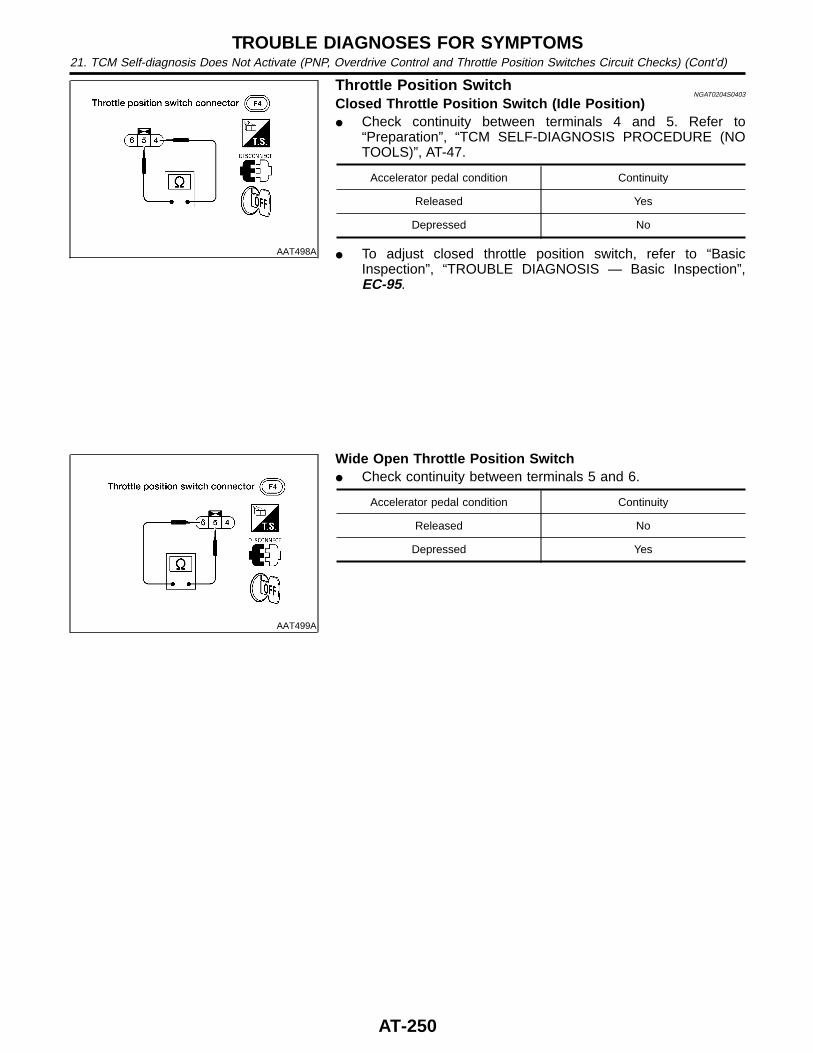
AAT498A
Throttle Position SwitchNGAT0204S0403
Closed Throttle Position Switch (Idle Position)I Check continuity between terminals 4 and 5. Refer to
“Preparation”, “TCM SELF-DIAGNOSIS PROCEDURE (NOTOOLS)”, AT-47.
Accelerator pedal condition Continuity
Released Yes
Depressed No
I To adjust closed throttle position switch, refer to “BasicInspection”, “TROUBLE DIAGNOSIS — Basic Inspection”,EC-95.
AAT499A
Wide Open Throttle Position SwitchI Check continuity between terminals 5 and 6.
Accelerator pedal condition Continuity
Released No
Depressed Yes
TROUBLE DIAGNOSES FOR SYMPTOMS21. TCM Self-diagnosis Does Not Activate (PNP, Overdrive Control and Throttle Position Switches Circuit Checks) (Cont’d)
AT-250
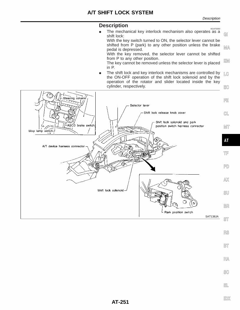
DescriptionNGAT0093
I The mechanical key interlock mechanism also operates as ashift lock:With the key switch turned to ON, the selector lever cannot beshifted from P (park) to any other position unless the brakepedal is depressed.With the key removed, the selector lever cannot be shiftedfrom P to any other position.The key cannot be removed unless the selector lever is placedin P.
I The shift lock and key interlock mechanisms are controlled bythe ON-OFF operation of the shift lock solenoid and by theoperation of the rotator and slider located inside the keycylinder, respectively.
SAT138JA
GI
MA
EM
LC
EC
FE
CL
MT
TF
PD
AX
SU
BR
ST
RS
BT
HA
SC
EL
IDX
A/T SHIFT LOCK SYSTEMDescription
AT-251
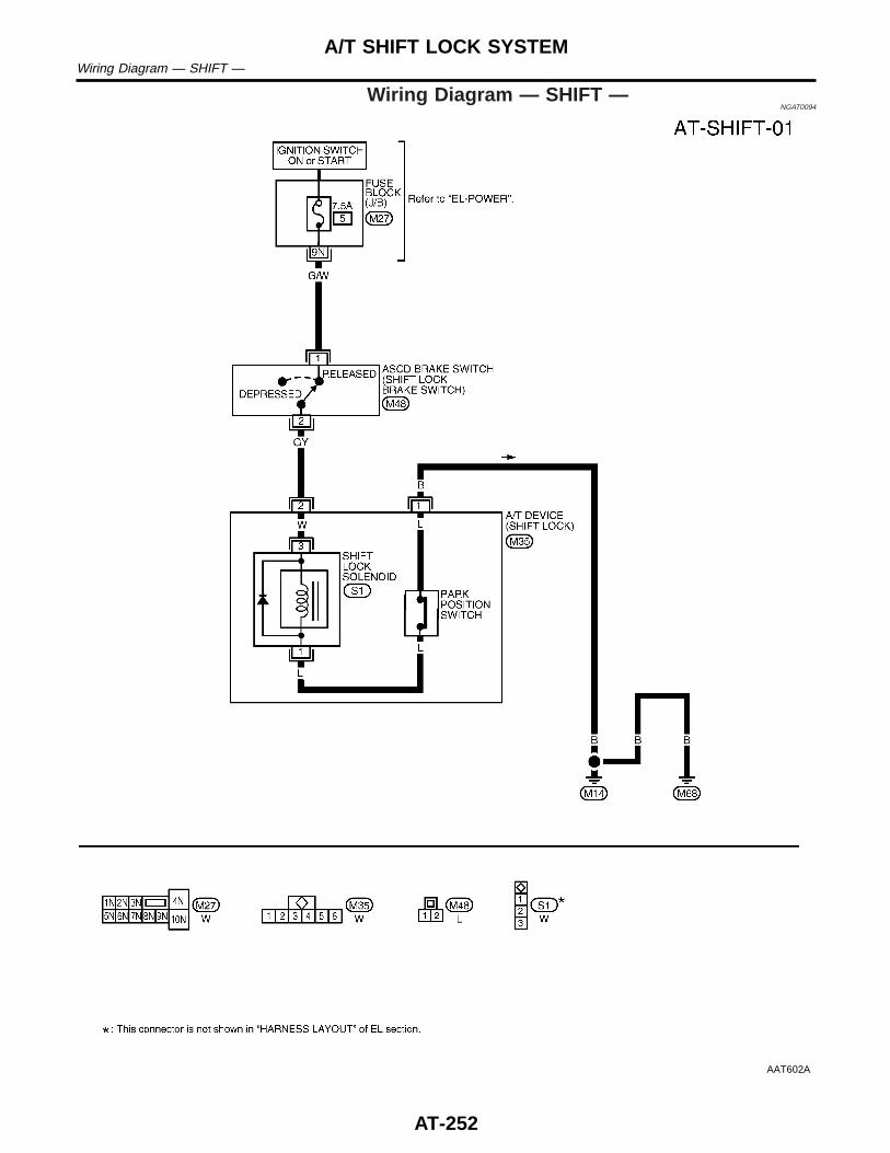
Wiring Diagram — SHIFT —NGAT0094
AAT602A
A/T SHIFT LOCK SYSTEMWiring Diagram — SHIFT —
AT-252
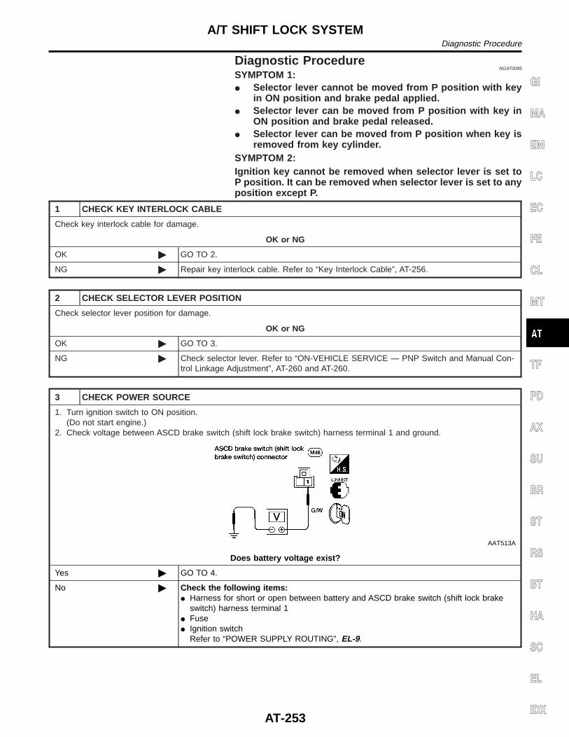
Diagnostic ProcedureNGAT0095
SYMPTOM 1:I Selector lever cannot be moved from P position with key
in ON position and brake pedal applied.I Selector lever can be moved from P position with key in
ON position and brake pedal released.I Selector lever can be moved from P position when key is
removed from key cylinder.SYMPTOM 2:Ignition key cannot be removed when selector lever is set toP position. It can be removed when selector lever is set to anyposition except P.
1 CHECK KEY INTERLOCK CABLE
Check key interlock cable for damage.
OK or NG
OK © GO TO 2.
NG © Repair key interlock cable. Refer to “Key Interlock Cable”, AT-256.
2 CHECK SELECTOR LEVER POSITION
Check selector lever position for damage.
OK or NG
OK © GO TO 3.
NG © Check selector lever. Refer to “ON-VEHICLE SERVICE — PNP Switch and Manual Con-trol Linkage Adjustment”, AT-260 and AT-260.
3 CHECK POWER SOURCE
1. Turn ignition switch to ON position.(Do not start engine.)
2. Check voltage between ASCD brake switch (shift lock brake switch) harness terminal 1 and ground.
AAT513A
Does battery voltage exist?
Yes © GO TO 4.
No © Check the following items:I Harness for short or open between battery and ASCD brake switch (shift lock brake
switch) harness terminal 1I FuseI Ignition switch
Refer to “POWER SUPPLY ROUTING”, EL-9.
GI
MA
EM
LC
EC
FE
CL
MT
TF
PD
AX
SU
BR
ST
RS
BT
HA
SC
EL
IDX
A/T SHIFT LOCK SYSTEMDiagnostic Procedure
AT-253
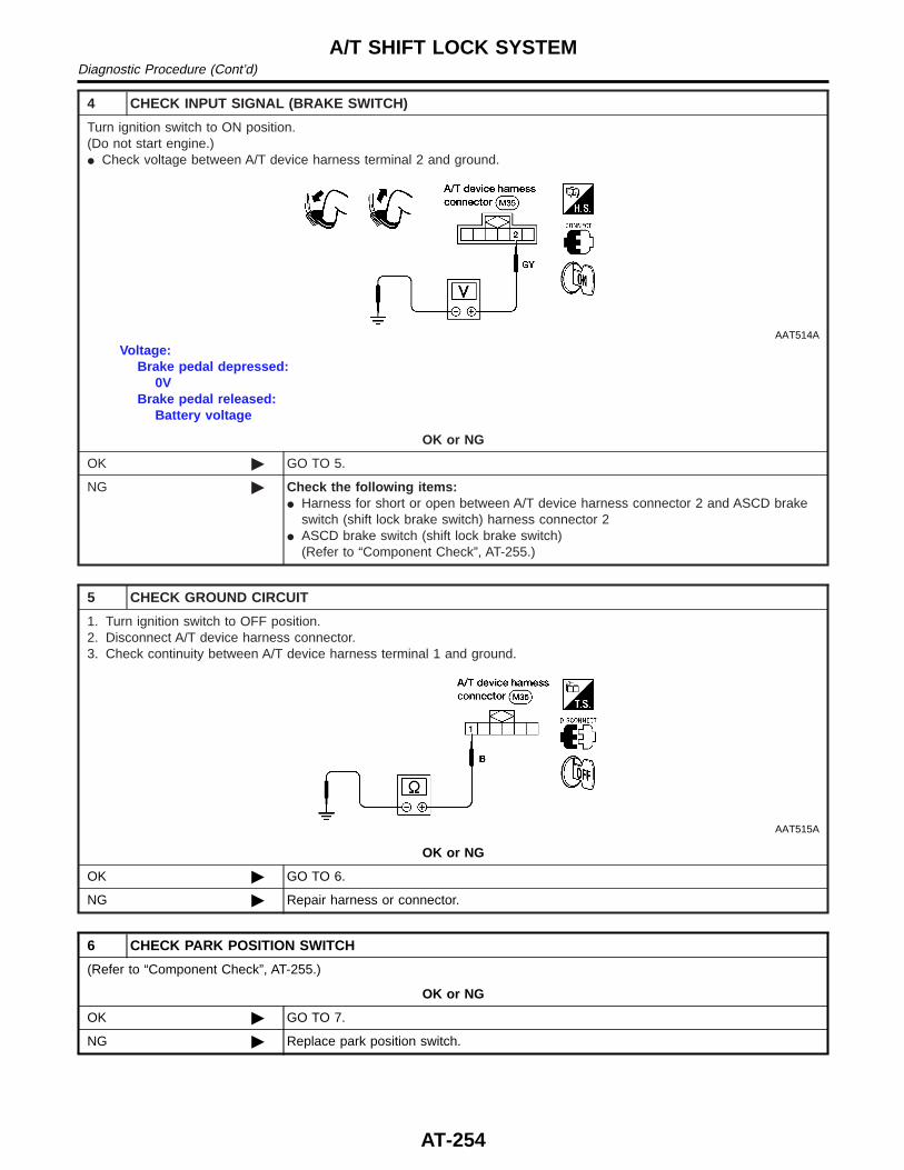
4 CHECK INPUT SIGNAL (BRAKE SWITCH)
Turn ignition switch to ON position.(Do not start engine.)I Check voltage between A/T device harness terminal 2 and ground.
AAT514A
Voltage:Brake pedal depressed:
0VBrake pedal released:
Battery voltage
OK or NG
OK © GO TO 5.
NG © Check the following items:I Harness for short or open between A/T device harness connector 2 and ASCD brake
switch (shift lock brake switch) harness connector 2I ASCD brake switch (shift lock brake switch)
(Refer to “Component Check”, AT-255.)
5 CHECK GROUND CIRCUIT
1. Turn ignition switch to OFF position.2. Disconnect A/T device harness connector.3. Check continuity between A/T device harness terminal 1 and ground.
AAT515A
OK or NG
OK © GO TO 6.
NG © Repair harness or connector.
6 CHECK PARK POSITION SWITCH
(Refer to “Component Check”, AT-255.)
OK or NG
OK © GO TO 7.
NG © Replace park position switch.
A/T SHIFT LOCK SYSTEMDiagnostic Procedure (Cont’d)
AT-254
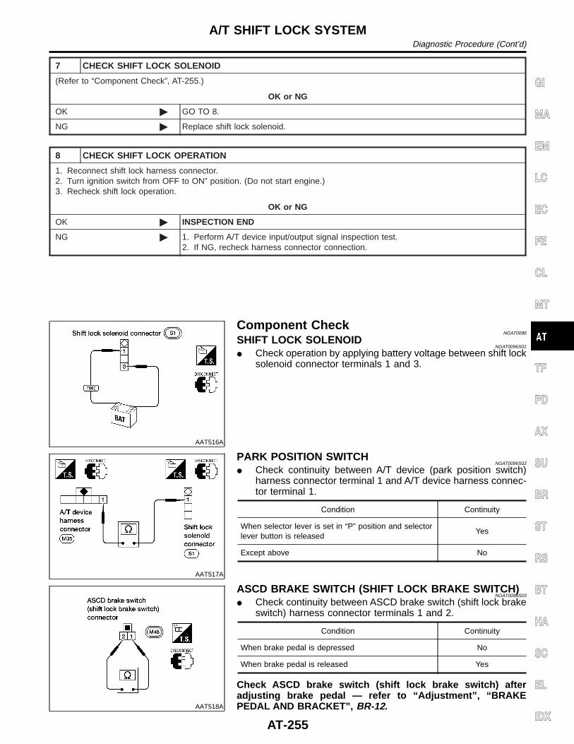
7 CHECK SHIFT LOCK SOLENOID
(Refer to “Component Check”, AT-255.)
OK or NG
OK © GO TO 8.
NG © Replace shift lock solenoid.
8 CHECK SHIFT LOCK OPERATION
1. Reconnect shift lock harness connector.2. Turn ignition switch from OFF to ON” position. (Do not start engine.)3. Recheck shift lock operation.
OK or NG
OK © INSPECTION END
NG © 1. Perform A/T device input/output signal inspection test.2. If NG, recheck harness connector connection.
AAT516A
Component CheckNGAT0096
SHIFT LOCK SOLENOIDNGAT0096S01
I Check operation by applying battery voltage between shift locksolenoid connector terminals 1 and 3.
AAT517A
PARK POSITION SWITCHNGAT0096S02
I Check continuity between A/T device (park position switch)harness connector terminal 1 and A/T device harness connec-tor terminal 1.
Condition Continuity
When selector lever is set in “P” position and selectorlever button is released
Yes
Except above No
AAT518A
ASCD BRAKE SWITCH (SHIFT LOCK BRAKE SWITCH)NGAT0096S03
I Check continuity between ASCD brake switch (shift lock brakeswitch) harness connector terminals 1 and 2.
Condition Continuity
When brake pedal is depressed No
When brake pedal is released Yes
Check ASCD brake switch (shift lock brake switch) afteradjusting brake pedal — refer to “Adjustment”, “BRAKEPEDAL AND BRACKET”, BR-12.
GI
MA
EM
LC
EC
FE
CL
MT
TF
PD
AX
SU
BR
ST
RS
BT
HA
SC
EL
IDX
A/T SHIFT LOCK SYSTEMDiagnostic Procedure (Cont’d)
AT-255
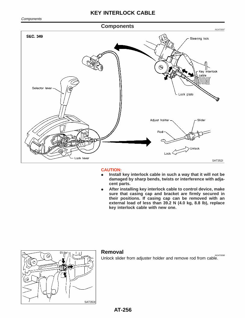
ComponentsNGAT0097
SAT352I
CAUTION:I Install key interlock cable in such a way that it will not be
damaged by sharp bends, twists or interference with adja-cent parts.
I After installing key interlock cable to control device, makesure that casing cap and bracket are firmly secured intheir positions. If casing cap can be removed with anexternal load of less than 39.2 N (4.0 kg, 8.8 lb), replacekey interlock cable with new one.
SAT353I
RemovalNGAT0098
Unlock slider from adjuster holder and remove rod from cable.
KEY INTERLOCK CABLEComponents
AT-256
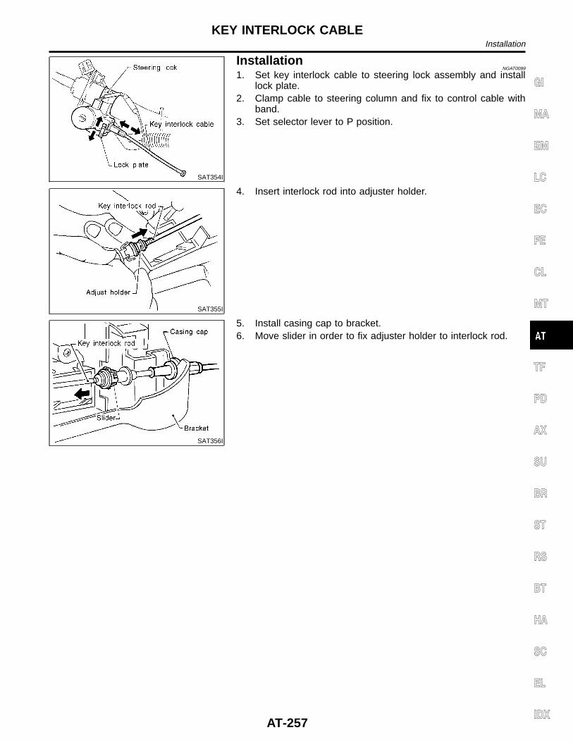
SAT354I
InstallationNGAT0099
1. Set key interlock cable to steering lock assembly and installlock plate.
2. Clamp cable to steering column and fix to control cable withband.
3. Set selector lever to P position.
SAT355I
4. Insert interlock rod into adjuster holder.
SAT356I
5. Install casing cap to bracket.6. Move slider in order to fix adjuster holder to interlock rod.
GI
MA
EM
LC
EC
FE
CL
MT
TF
PD
AX
SU
BR
ST
RS
BT
HA
SC
EL
IDX
KEY INTERLOCK CABLEInstallation
AT-257
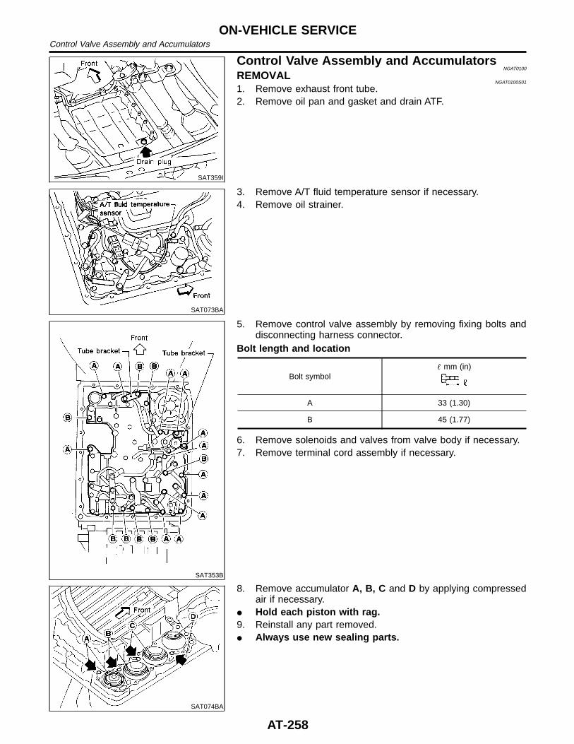
SAT359I
Control Valve Assembly and AccumulatorsNGAT0100
REMOVALNGAT0100S01
1. Remove exhaust front tube.2. Remove oil pan and gasket and drain ATF.
SAT073BA
3. Remove A/T fluid temperature sensor if necessary.4. Remove oil strainer.
SAT353B
5. Remove control valve assembly by removing fixing bolts anddisconnecting harness connector.
Bolt length and location
Bolt symbol mm (in)
A 33 (1.30)
B 45 (1.77)
6. Remove solenoids and valves from valve body if necessary.7. Remove terminal cord assembly if necessary.
SAT074BA
8. Remove accumulator A, B, C and D by applying compressedair if necessary.
I Hold each piston with rag.9. Reinstall any part removed.I Always use new sealing parts.
ON-VEHICLE SERVICEControl Valve Assembly and Accumulators
AT-258
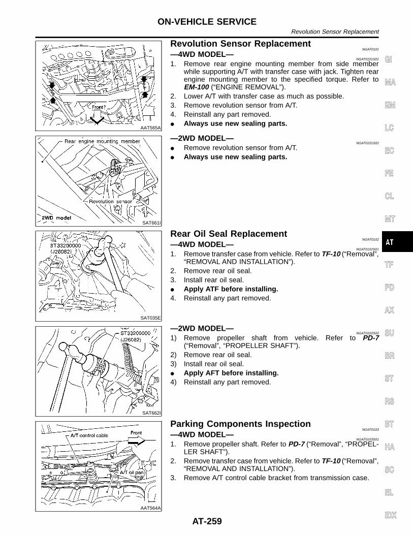
AAT565A
Revolution Sensor ReplacementNGAT0101
—4WD MODEL—NGAT0101S01
1. Remove rear engine mounting member from side memberwhile supporting A/T with transfer case with jack. Tighten rearengine mounting member to the specified torque. Refer toEM-100 (“ENGINE REMOVAL”).
2. Lower A/T with transfer case as much as possible.3. Remove revolution sensor from A/T.4. Reinstall any part removed.I Always use new sealing parts.
SAT661I
—2WD MODEL—NGAT0101S02
I Remove revolution sensor from A/T.I Always use new sealing parts.
SAT035E
Rear Oil Seal ReplacementNGAT0102
—4WD MODEL—NGAT0102S01
1. Remove transfer case from vehicle. Refer to TF-10 (“Removal”,“REMOVAL AND INSTALLATION”).
2. Remove rear oil seal.3. Install rear oil seal.I Apply ATF before installing.4. Reinstall any part removed.
SAT662I
—2WD MODEL—NGAT0102S02
1) Remove propeller shaft from vehicle. Refer to PD-7(“Removal”, “PROPELLER SHAFT”).
2) Remove rear oil seal.3) Install rear oil seal.I Apply AFT before installing.4) Reinstall any part removed.
AAT564A
Parking Components InspectionNGAT0103
—4WD MODEL—NGAT0103S01
1. Remove propeller shaft. Refer to PD-7 (“Removal”, “PROPEL-LER SHAFT”).
2. Remove transfer case from vehicle. Refer to TF-10 (“Removal”,“REMOVAL AND INSTALLATION”).
3. Remove A/T control cable bracket from transmission case.
GI
MA
EM
LC
EC
FE
CL
MT
TF
PD
AX
SU
BR
ST
RS
BT
HA
SC
EL
IDX
ON-VEHICLE SERVICERevolution Sensor Replacement
AT-259
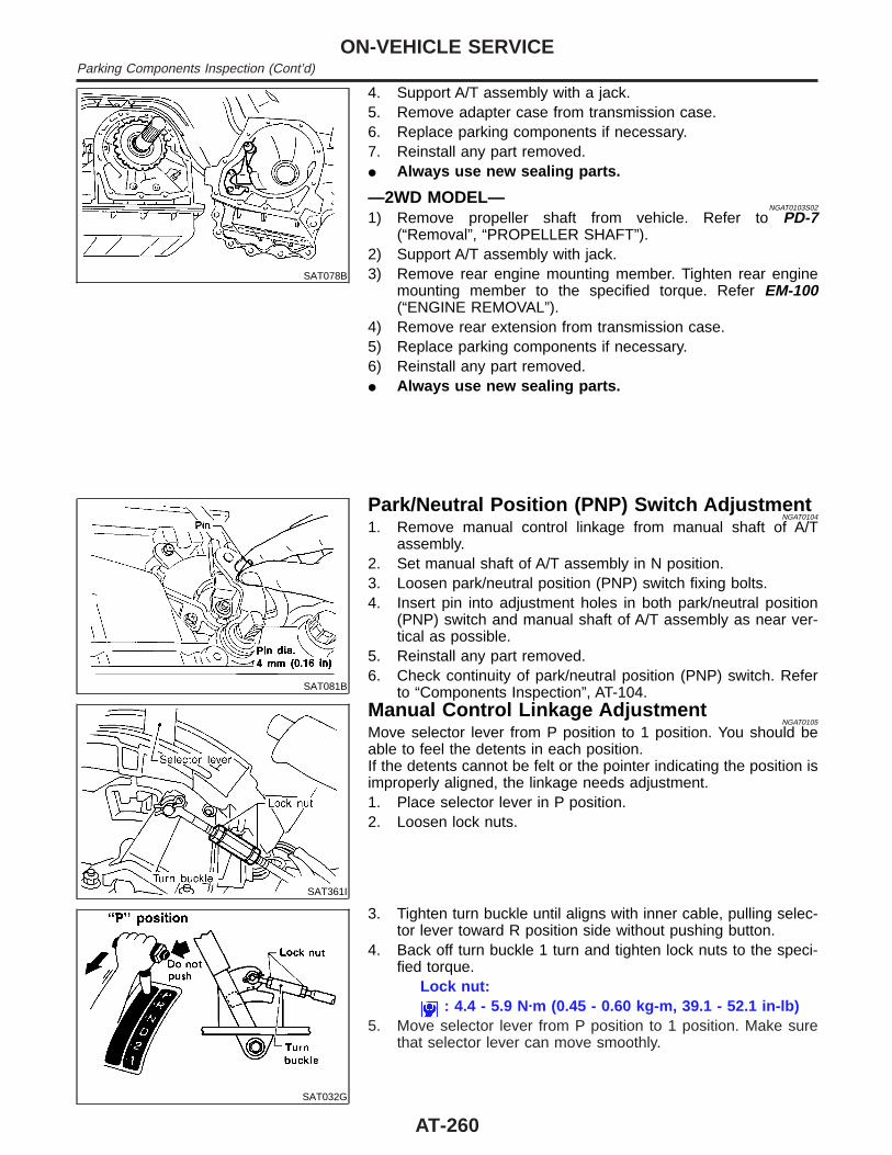
SAT078B
4. Support A/T assembly with a jack.5. Remove adapter case from transmission case.6. Replace parking components if necessary.7. Reinstall any part removed.I Always use new sealing parts.
—2WD MODEL—NGAT0103S02
1) Remove propeller shaft from vehicle. Refer to PD-7(“Removal”, “PROPELLER SHAFT”).
2) Support A/T assembly with jack.3) Remove rear engine mounting member. Tighten rear engine
mounting member to the specified torque. Refer EM-100(“ENGINE REMOVAL”).
4) Remove rear extension from transmission case.5) Replace parking components if necessary.6) Reinstall any part removed.I Always use new sealing parts.
SAT081B
Park/Neutral Position (PNP) Switch AdjustmentNGAT0104
1. Remove manual control linkage from manual shaft of A/Tassembly.
2. Set manual shaft of A/T assembly in N position.3. Loosen park/neutral position (PNP) switch fixing bolts.4. Insert pin into adjustment holes in both park/neutral position
(PNP) switch and manual shaft of A/T assembly as near ver-tical as possible.
5. Reinstall any part removed.6. Check continuity of park/neutral position (PNP) switch. Refer
to “Components Inspection”, AT-104.
SAT361I
Manual Control Linkage AdjustmentNGAT0105
Move selector lever from P position to 1 position. You should beable to feel the detents in each position.If the detents cannot be felt or the pointer indicating the position isimproperly aligned, the linkage needs adjustment.1. Place selector lever in P position.2. Loosen lock nuts.
SAT032G
3. Tighten turn buckle until aligns with inner cable, pulling selec-tor lever toward R position side without pushing button.
4. Back off turn buckle 1 turn and tighten lock nuts to the speci-fied torque.
Lock nut:: 4.4 - 5.9 N·m (0.45 - 0.60 kg-m, 39.1 - 52.1 in-lb)
5. Move selector lever from P position to 1 position. Make surethat selector lever can move smoothly.
ON-VEHICLE SERVICEParking Components Inspection (Cont’d)
AT-260
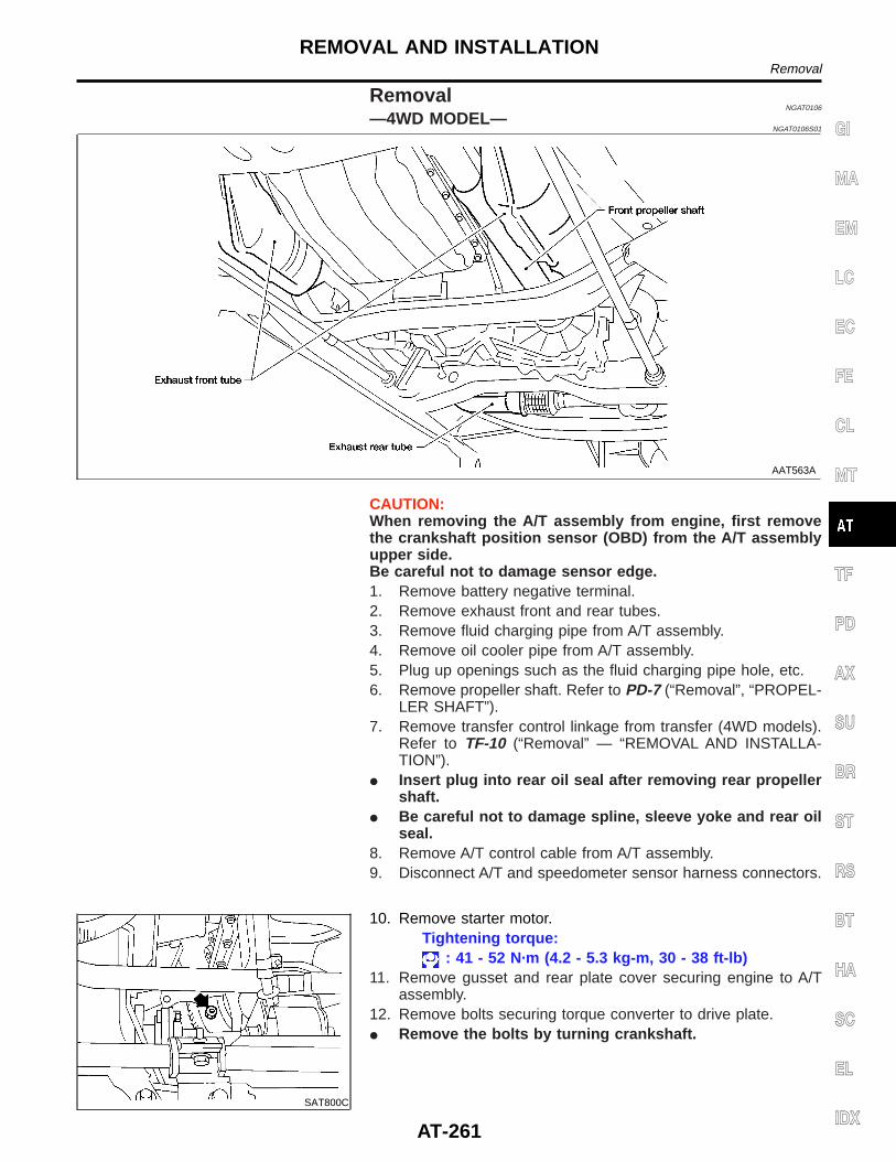
RemovalNGAT0106
—4WD MODEL—NGAT0106S01
AAT563A
CAUTION:When removing the A/T assembly from engine, first removethe crankshaft position sensor (OBD) from the A/T assemblyupper side.Be careful not to damage sensor edge.1. Remove battery negative terminal.2. Remove exhaust front and rear tubes.3. Remove fluid charging pipe from A/T assembly.4. Remove oil cooler pipe from A/T assembly.5. Plug up openings such as the fluid charging pipe hole, etc.6. Remove propeller shaft. Refer to PD-7 (“Removal”, “PROPEL-
LER SHAFT”).7. Remove transfer control linkage from transfer (4WD models).
Refer to TF-10 (“Removal” — “REMOVAL AND INSTALLA-TION”).
I Insert plug into rear oil seal after removing rear propellershaft.
I Be careful not to damage spline, sleeve yoke and rear oilseal.
8. Remove A/T control cable from A/T assembly.9. Disconnect A/T and speedometer sensor harness connectors.
SAT800C
10. Remove starter motor.Tightening torque:
: 41 - 52 N·m (4.2 - 5.3 kg-m, 30 - 38 ft-lb)11. Remove gusset and rear plate cover securing engine to A/T
assembly.12. Remove bolts securing torque converter to drive plate.I Remove the bolts by turning crankshaft.
GI
MA
EM
LC
EC
FE
CL
MT
TF
PD
AX
SU
BR
ST
RS
BT
HA
SC
EL
IDX
REMOVAL AND INSTALLATIONRemoval
AT-261
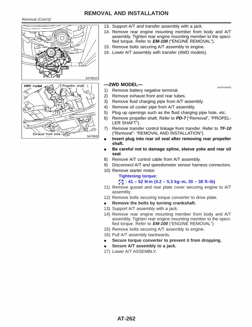
SAT801C
13. Support A/T and transfer assembly with a jack.14. Remove rear engine mounting member from body and A/T
assembly. Tighten rear engine mounting member to the speci-fied torque. Refer to EM-100 (“ENGINE REMOVAL”).
15. Remove bolts securing A/T assembly to engine.16. Lower A/T assembly with transfer (4WD models).
SAT663I
—2WD MODEL—NGAT0106S02
1) Remove battery negative terminal.2) Remove exhaust front and rear tubes.3) Remove fluid charging pipe from A/T assembly.4) Remove oil cooler pipe from A/T assembly.5) Plug up openings such as the fluid charging pipe hole, etc.6) Remove propeller shaft. Refer to PD-7 (“Removal”, “PROPEL-
LER SHAFT”).7) Remove transfer control linkage from transfer. Refer to TF-10
(“Removal”- “REMOVAL AND INSTALLATION”).I Insert plug into rear oil seal after removing rear propeller
shaft.I Be careful not to damage spline, sleeve yoke and rear oil
seal .8) Remove A/T control cable from A/T assembly.9) Disconnect A/T and speedometer sensor harness connectors.10) Remove starter motor.
Tightening torque:: 41 – 52 N·m (4.2 – 5.3 kg–m, 30 – 38 ft–lb)
11) Remove gusset and rear plate cover securing engine to A/Tassembly.
12) Remove bolts securing torque converter to drive plate.I Remove the bolts by turning crankshaft.13) Support A/T assembly with a jack.14) Remove rear engine mounting member from body and A/T
assembly. Tighten rear engine mounting member to the speci-fied torque. Refer to EM-100 (“ENGINE REMOVAL”).
15) Remove bolts securing A/T assembly to engine.16) Pull A/T assembly backwards.I Secure torque converter to prevent it from dropping.I Secure A/T assembly to a jack.17) Lower A/T ASSEMBLY.
REMOVAL AND INSTALLATIONRemoval (Cont’d)
AT-262
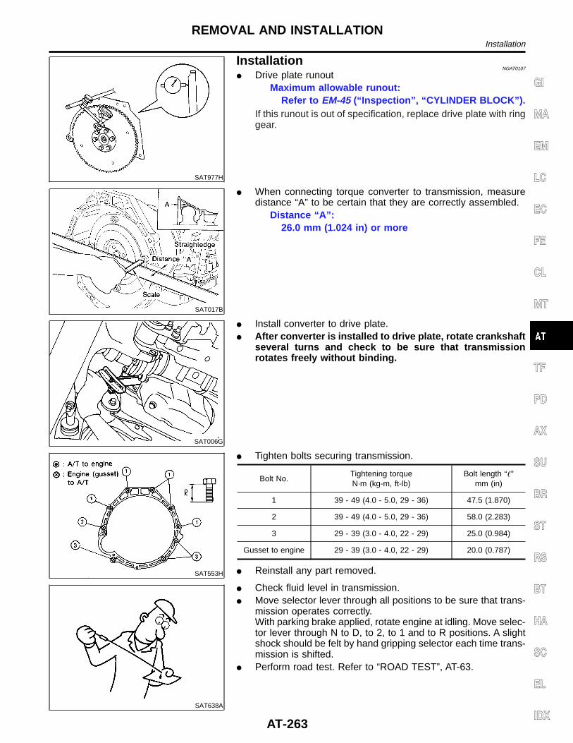
SAT977H
InstallationNGAT0107
I Drive plate runoutMaximum allowable runout:
Refer to EM-45 (“Inspection”, “CYLINDER BLOCK”).If this runout is out of specification, replace drive plate with ringgear.
SAT017B
I When connecting torque converter to transmission, measuredistance “A” to be certain that they are correctly assembled.
Distance “A”:26.0 mm (1.024 in) or more
SAT006G
I Install converter to drive plate.I After converter is installed to drive plate, rotate crankshaft
several turns and check to be sure that transmissionrotates freely without binding.
SAT553H
I Tighten bolts securing transmission.
Bolt No.Tightening torqueN·m (kg-m, ft-lb)
Bolt length “”mm (in)
1 39 - 49 (4.0 - 5.0, 29 - 36) 47.5 (1.870)
2 39 - 49 (4.0 - 5.0, 29 - 36) 58.0 (2.283)
3 29 - 39 (3.0 - 4.0, 22 - 29) 25.0 (0.984)
Gusset to engine 29 - 39 (3.0 - 4.0, 22 - 29) 20.0 (0.787)
I Reinstall any part removed.
SAT638A
I Check fluid level in transmission.I Move selector lever through all positions to be sure that trans-
mission operates correctly.With parking brake applied, rotate engine at idling. Move selec-tor lever through N to D, to 2, to 1 and to R positions. A slightshock should be felt by hand gripping selector each time trans-mission is shifted.
I Perform road test. Refer to “ROAD TEST”, AT-63.
GI
MA
EM
LC
EC
FE
CL
MT
TF
PD
AX
SU
BR
ST
RS
BT
HA
SC
EL
IDX
REMOVAL AND INSTALLATIONInstallation
AT-263
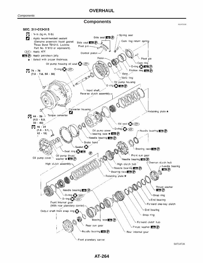
ComponentsNGAT0108
SAT147JA
OVERHAULComponents
AT-264
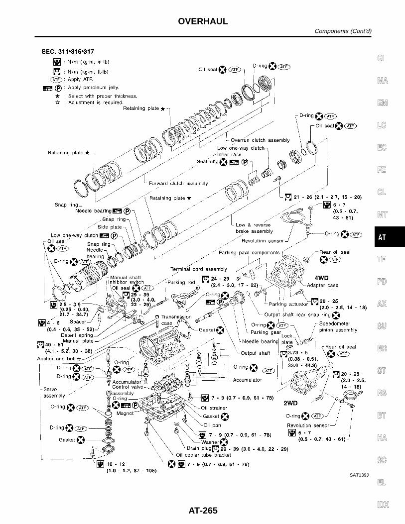
SAT139J
GI
MA
EM
LC
EC
FE
CL
MT
TF
PD
AX
SU
BR
ST
RS
BT
HA
SC
EL
IDX
OVERHAULComponents (Cont’d)
AT-265
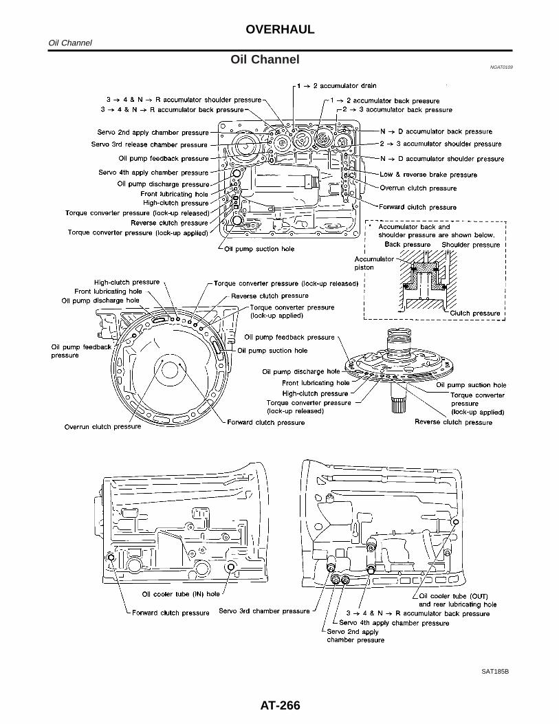
Oil ChannelNGAT0109
SAT185B
OVERHAULOil Channel
AT-266
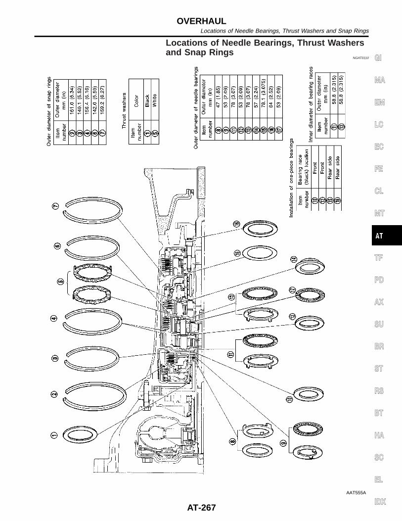
Locations of Needle Bearings, Thrust Washersand Snap Rings
NGAT0110
AAT555A
GI
MA
EM
LC
EC
FE
CL
MT
TF
PD
AX
SU
BR
ST
RS
BT
HA
SC
EL
IDX
OVERHAULLocations of Needle Bearings, Thrust Washers and Snap Rings
AT-267
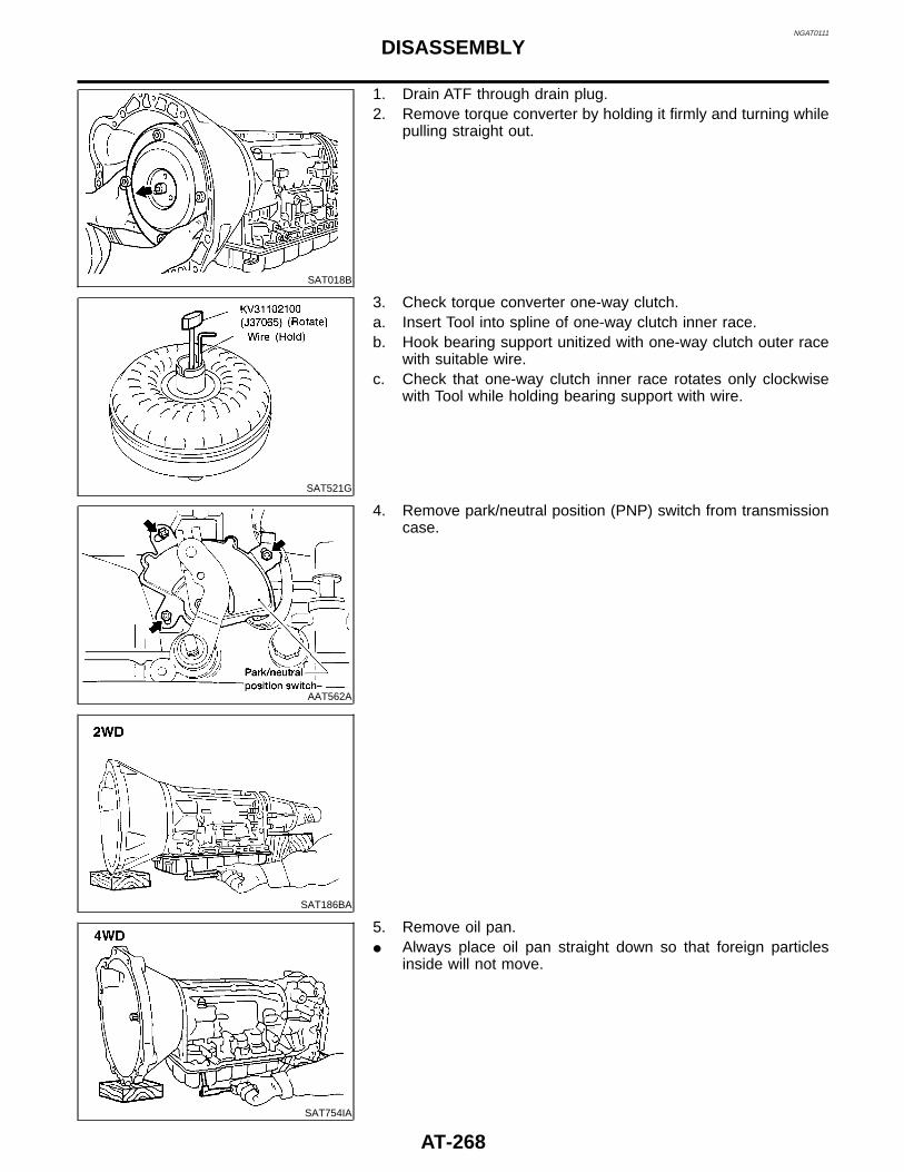
NGAT0111
SAT018B
1. Drain ATF through drain plug.2. Remove torque converter by holding it firmly and turning while
pulling straight out.
SAT521G
3. Check torque converter one-way clutch.a. Insert Tool into spline of one-way clutch inner race.b. Hook bearing support unitized with one-way clutch outer race
with suitable wire.c. Check that one-way clutch inner race rotates only clockwise
with Tool while holding bearing support with wire.
AAT562A
4. Remove park/neutral position (PNP) switch from transmissioncase.
SAT186BA
SAT754IA
5. Remove oil pan.I Always place oil pan straight down so that foreign particles
inside will not move.
DISASSEMBLY
AT-268
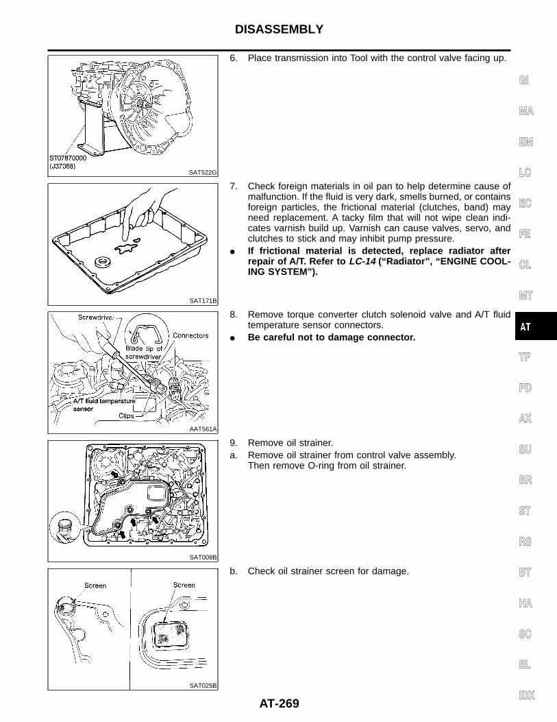
SAT522G
6. Place transmission into Tool with the control valve facing up.
SAT171B
7. Check foreign materials in oil pan to help determine cause ofmalfunction. If the fluid is very dark, smells burned, or containsforeign particles, the frictional material (clutches, band) mayneed replacement. A tacky film that will not wipe clean indi-cates varnish build up. Varnish can cause valves, servo, andclutches to stick and may inhibit pump pressure.
I If frictional material is detected, replace radiator afterrepair of A/T. Refer to LC-14 (“Radiator”, “ENGINE COOL-ING SYSTEM”).
AAT561A
8. Remove torque converter clutch solenoid valve and A/T fluidtemperature sensor connectors.
I Be careful not to damage connector.
SAT008B
9. Remove oil strainer.a. Remove oil strainer from control valve assembly.
Then remove O-ring from oil strainer.
SAT025B
b. Check oil strainer screen for damage.
GI
MA
EM
LC
EC
FE
CL
MT
TF
PD
AX
SU
BR
ST
RS
BT
HA
SC
EL
IDX
DISASSEMBLY
AT-269
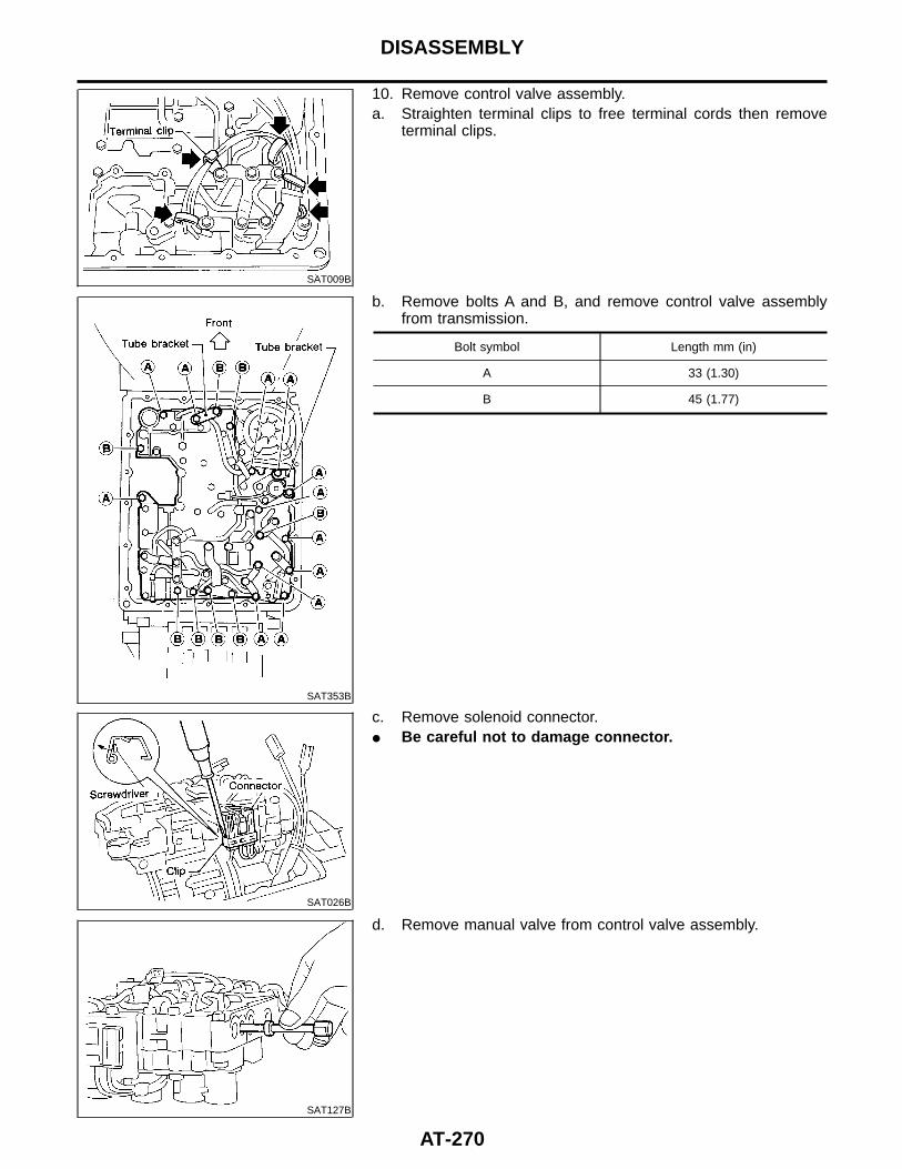
SAT009B
10. Remove control valve assembly.a. Straighten terminal clips to free terminal cords then remove
terminal clips.
SAT353B
b. Remove bolts A and B, and remove control valve assemblyfrom transmission.
Bolt symbol Length mm (in)
A 33 (1.30)
B 45 (1.77)
SAT026B
c. Remove solenoid connector.I Be careful not to damage connector.
SAT127B
d. Remove manual valve from control valve assembly.
DISASSEMBLY
AT-270
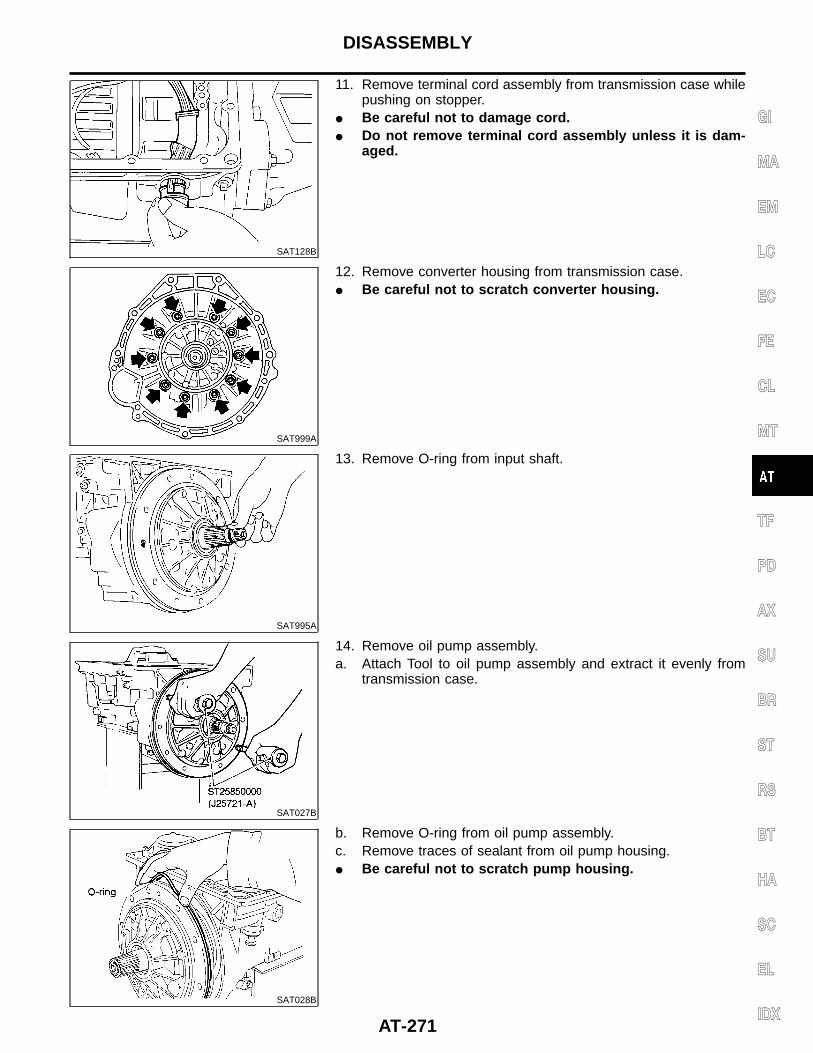
SAT128B
11. Remove terminal cord assembly from transmission case whilepushing on stopper.
I Be careful not to damage cord.I Do not remove terminal cord assembly unless it is dam-
aged.
SAT999A
12. Remove converter housing from transmission case.I Be careful not to scratch converter housing.
SAT995A
13. Remove O-ring from input shaft.
SAT027B
14. Remove oil pump assembly.a. Attach Tool to oil pump assembly and extract it evenly from
transmission case.
SAT028B
b. Remove O-ring from oil pump assembly.c. Remove traces of sealant from oil pump housing.I Be careful not to scratch pump housing.
GI
MA
EM
LC
EC
FE
CL
MT
TF
PD
AX
SU
BR
ST
RS
BT
HA
SC
EL
IDX
DISASSEMBLY
AT-271
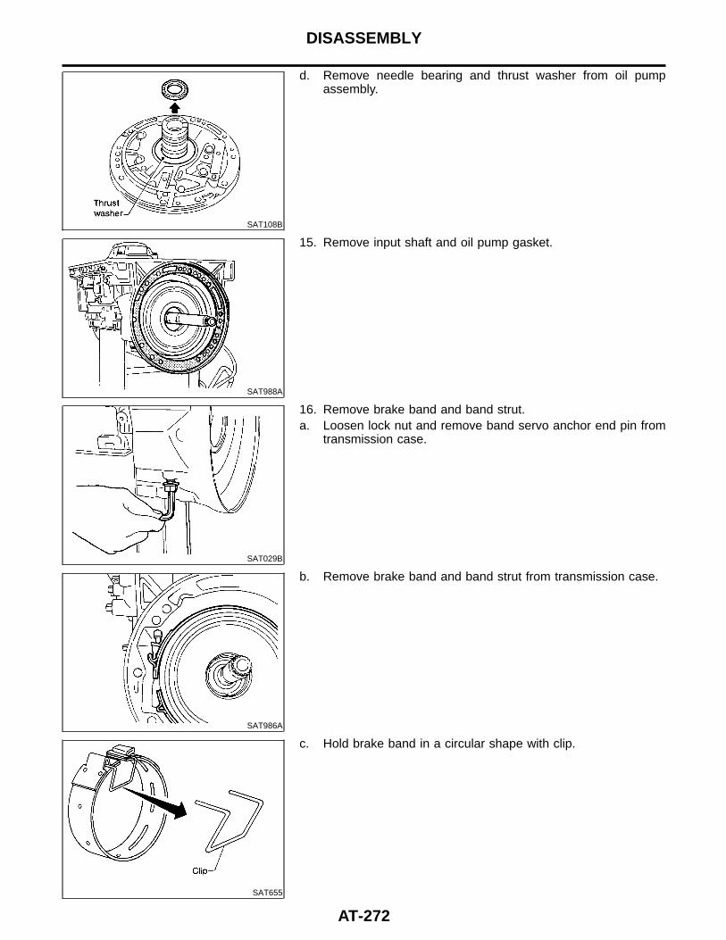
SAT108B
d. Remove needle bearing and thrust washer from oil pumpassembly.
SAT988A
15. Remove input shaft and oil pump gasket.
SAT029B
16. Remove brake band and band strut.a. Loosen lock nut and remove band servo anchor end pin from
transmission case.
SAT986A
b. Remove brake band and band strut from transmission case.
SAT655
c. Hold brake band in a circular shape with clip.
DISASSEMBLY
AT-272
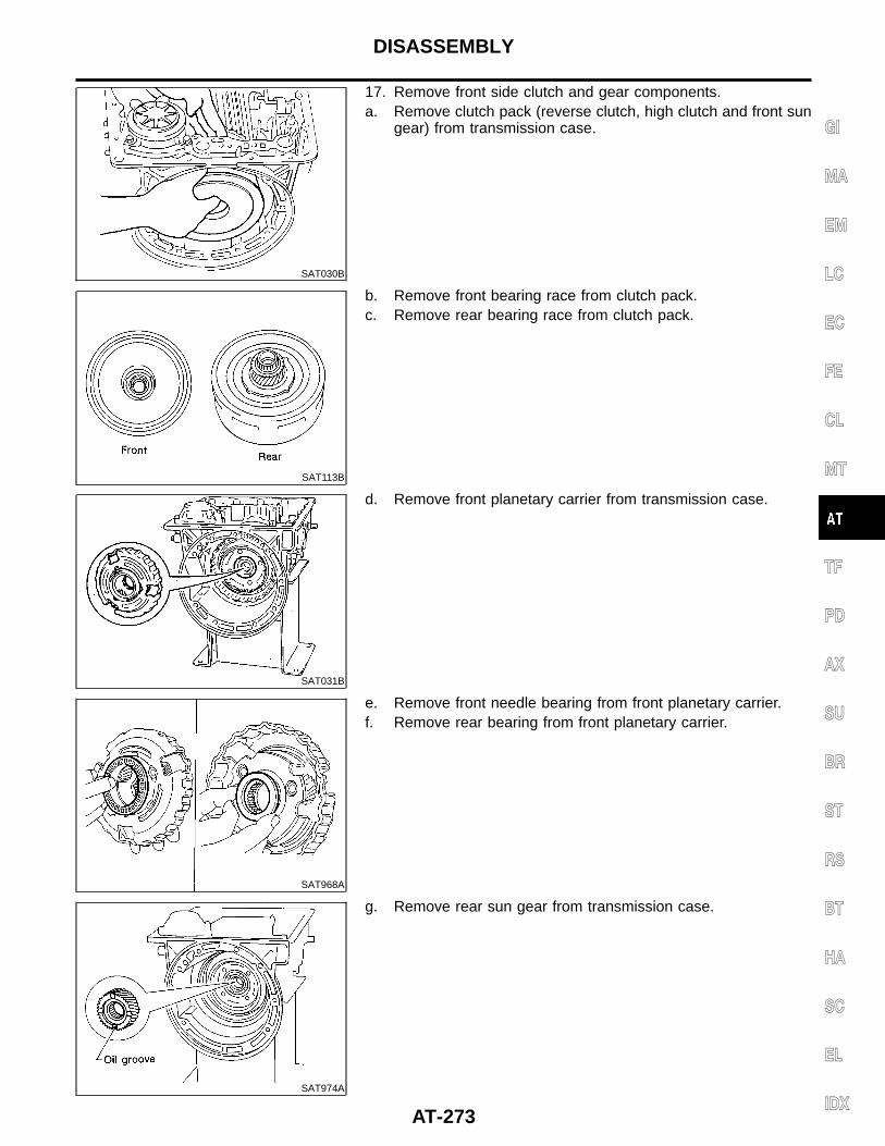
SAT030B
17. Remove front side clutch and gear components.a. Remove clutch pack (reverse clutch, high clutch and front sun
gear) from transmission case.
SAT113B
b. Remove front bearing race from clutch pack.c. Remove rear bearing race from clutch pack.
SAT031B
d. Remove front planetary carrier from transmission case.
SAT968A
e. Remove front needle bearing from front planetary carrier.f. Remove rear bearing from front planetary carrier.
SAT974A
g. Remove rear sun gear from transmission case.
GI
MA
EM
LC
EC
FE
CL
MT
TF
PD
AX
SU
BR
ST
RS
BT
HA
SC
EL
IDX
DISASSEMBLY
AT-273
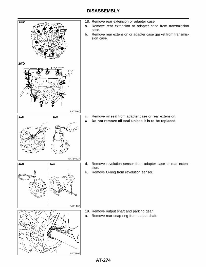
SAT716C
18. Remove rear extension or adapter case.a. Remove rear extension or adapter case from transmission
case.b. Remove rear extension or adapter case gasket from transmis-
sion case.
SAT146GA
c. Remove oil seal from adapter case or rear extension.I Do not remove oil seal unless it is to be replaced.
SAT147G
d. Remove revolution sensor from adapter case or rear exten-sion.
e. Remove O-ring from revolution sensor.
SAT960A
19. Remove output shaft and parking gear.a. Remove rear snap ring from output shaft.
DISASSEMBLY
AT-274
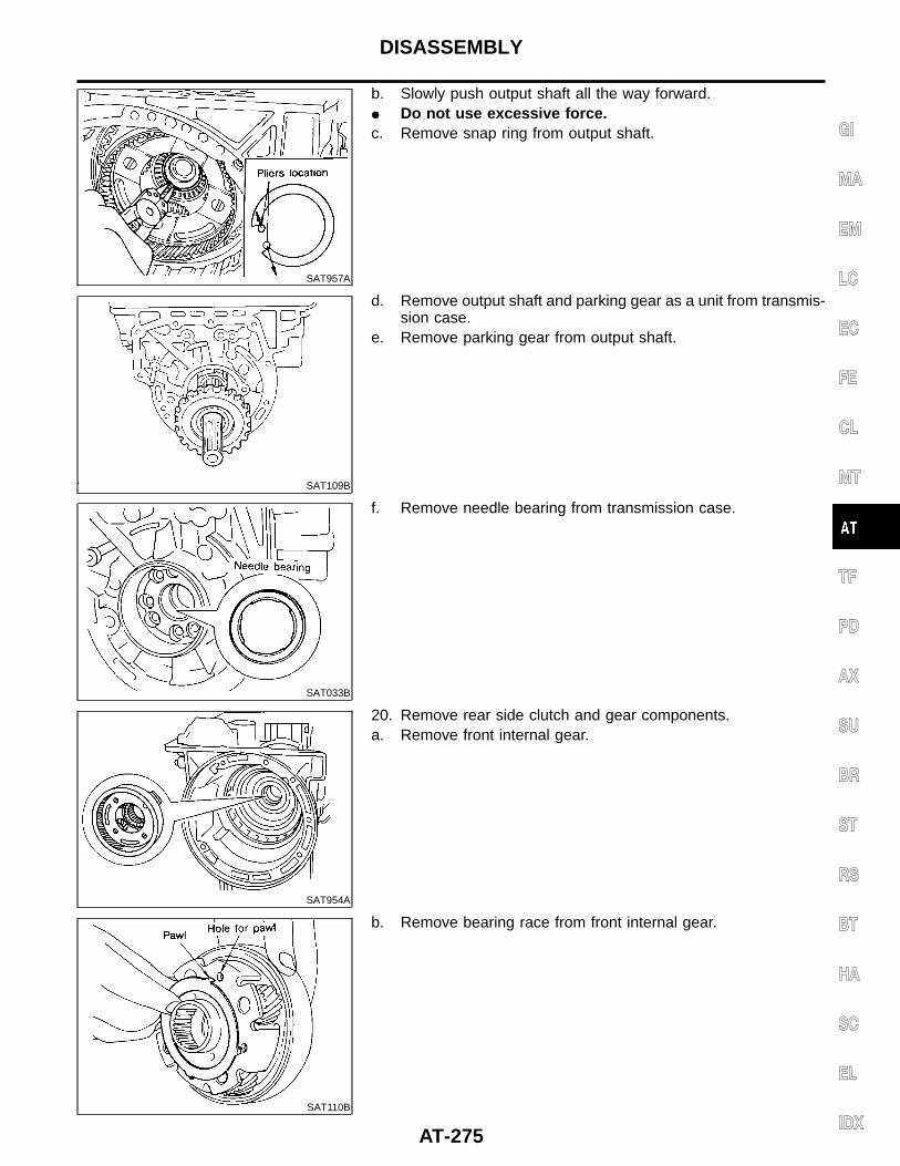
SAT957A
b. Slowly push output shaft all the way forward.I Do not use excessive force.c. Remove snap ring from output shaft.
SAT109B
d. Remove output shaft and parking gear as a unit from transmis-sion case.
e. Remove parking gear from output shaft.
SAT033B
f. Remove needle bearing from transmission case.
SAT954A
20. Remove rear side clutch and gear components.a. Remove front internal gear.
SAT110B
b. Remove bearing race from front internal gear.
GI
MA
EM
LC
EC
FE
CL
MT
TF
PD
AX
SU
BR
ST
RS
BT
HA
SC
EL
IDX
DISASSEMBLY
AT-275
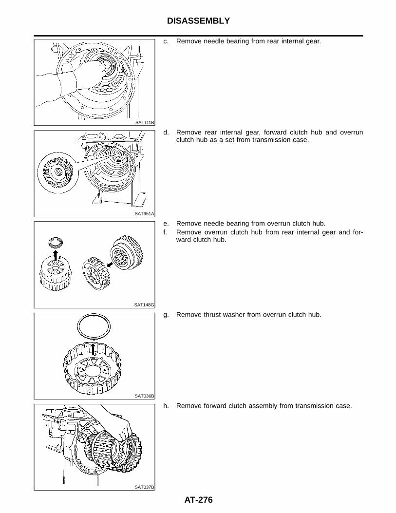
SAT111B
c. Remove needle bearing from rear internal gear.
SAT951A
d. Remove rear internal gear, forward clutch hub and overrunclutch hub as a set from transmission case.
SAT148G
e. Remove needle bearing from overrun clutch hub.f. Remove overrun clutch hub from rear internal gear and for-
ward clutch hub.
SAT036B
g. Remove thrust washer from overrun clutch hub.
SAT037B
h. Remove forward clutch assembly from transmission case.
DISASSEMBLY
AT-276
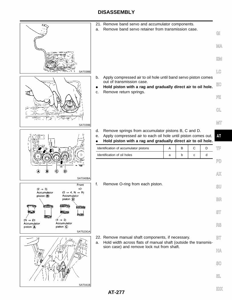
SAT038B
21. Remove band servo and accumulator components.a. Remove band servo retainer from transmission case.
SAT039B
b. Apply compressed air to oil hole until band servo piston comesout of transmission case.
I Hold piston with a rag and gradually direct air to oil hole.c. Remove return springs.
SAT040BA
d. Remove springs from accumulator pistons B, C and D.e. Apply compressed air to each oil hole until piston comes out.I Hold piston with a rag and gradually direct air to oil hole.
Identification of accumulator pistons A B C D
Identification of oil holes a b c d
SAT523GA
f. Remove O-ring from each piston.
SAT041B
22. Remove manual shaft components, if necessary.a. Hold width across flats of manual shaft (outside the transmis-
sion case) and remove lock nut from shaft.
GI
MA
EM
LC
EC
FE
CL
MT
TF
PD
AX
SU
BR
ST
RS
BT
HA
SC
EL
IDX
DISASSEMBLY
AT-277
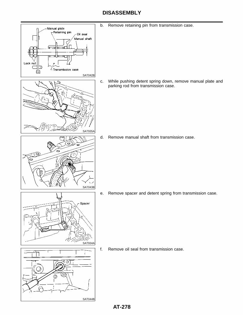
SAT042B
b. Remove retaining pin from transmission case.
SAT935A
c. While pushing detent spring down, remove manual plate andparking rod from transmission case.
SAT043B
d. Remove manual shaft from transmission case.
SAT934A
e. Remove spacer and detent spring from transmission case.
SAT044B
f. Remove oil seal from transmission case.
DISASSEMBLY
AT-278
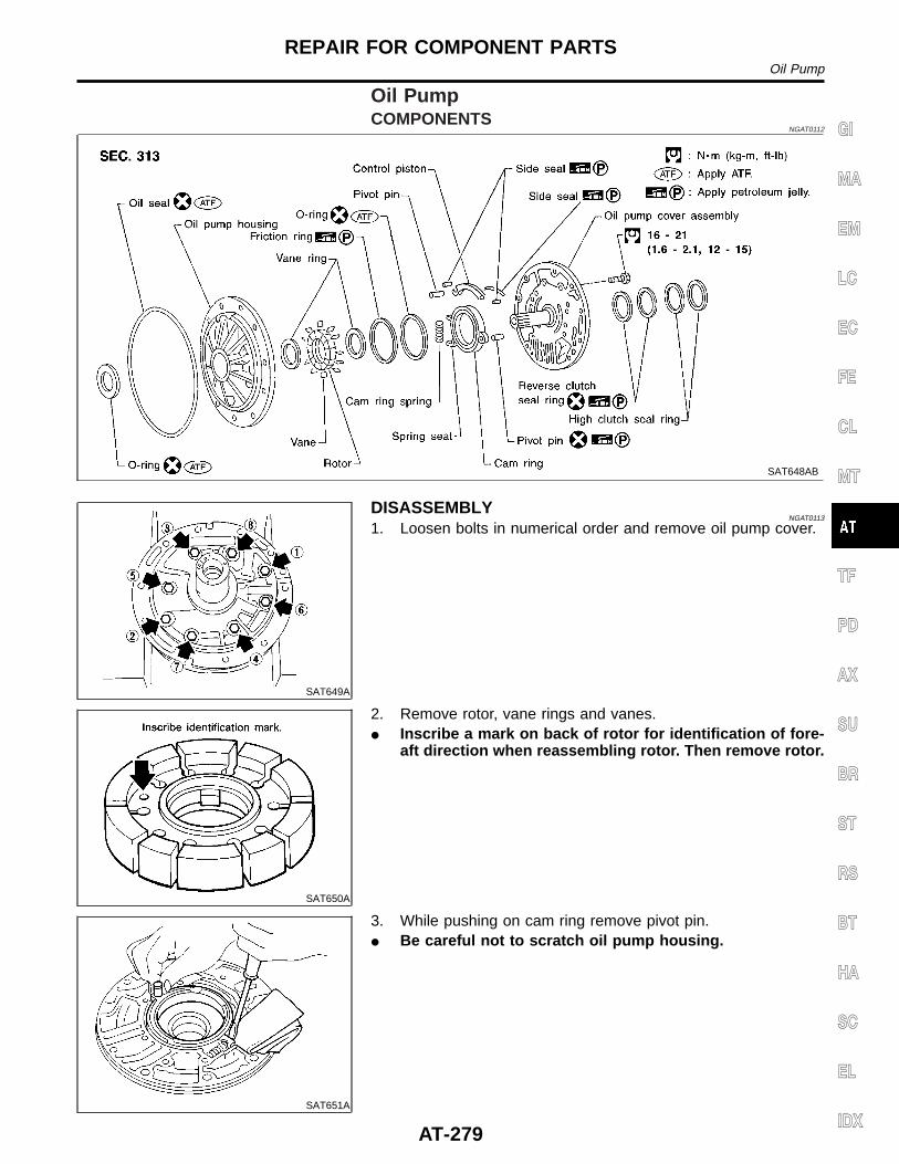
Oil PumpCOMPONENTS
NGAT0112
SAT648AB
SAT649A
DISASSEMBLYNGAT0113
1. Loosen bolts in numerical order and remove oil pump cover.
SAT650A
2. Remove rotor, vane rings and vanes.I Inscribe a mark on back of rotor for identification of fore-
aft direction when reassembling rotor. Then remove rotor.
SAT651A
3. While pushing on cam ring remove pivot pin.I Be careful not to scratch oil pump housing.
GI
MA
EM
LC
EC
FE
CL
MT
TF
PD
AX
SU
BR
ST
RS
BT
HA
SC
EL
IDX
REPAIR FOR COMPONENT PARTSOil Pump
AT-279
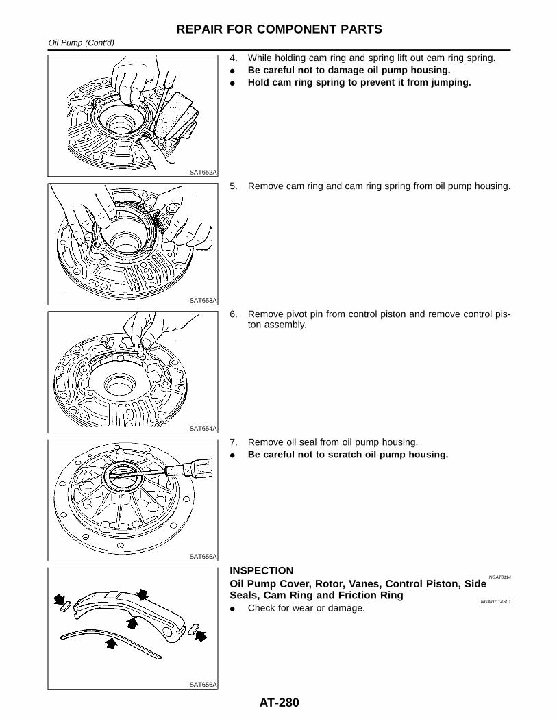
SAT652A
4. While holding cam ring and spring lift out cam ring spring.I Be careful not to damage oil pump housing.I Hold cam ring spring to prevent it from jumping.
SAT653A
5. Remove cam ring and cam ring spring from oil pump housing.
SAT654A
6. Remove pivot pin from control piston and remove control pis-ton assembly.
SAT655A
7. Remove oil seal from oil pump housing.I Be careful not to scratch oil pump housing.
SAT656A
INSPECTIONNGAT0114
Oil Pump Cover, Rotor, Vanes, Control Piston, SideSeals, Cam Ring and Friction Ring
NGAT0114S01
I Check for wear or damage.
REPAIR FOR COMPONENT PARTSOil Pump (Cont’d)
AT-280
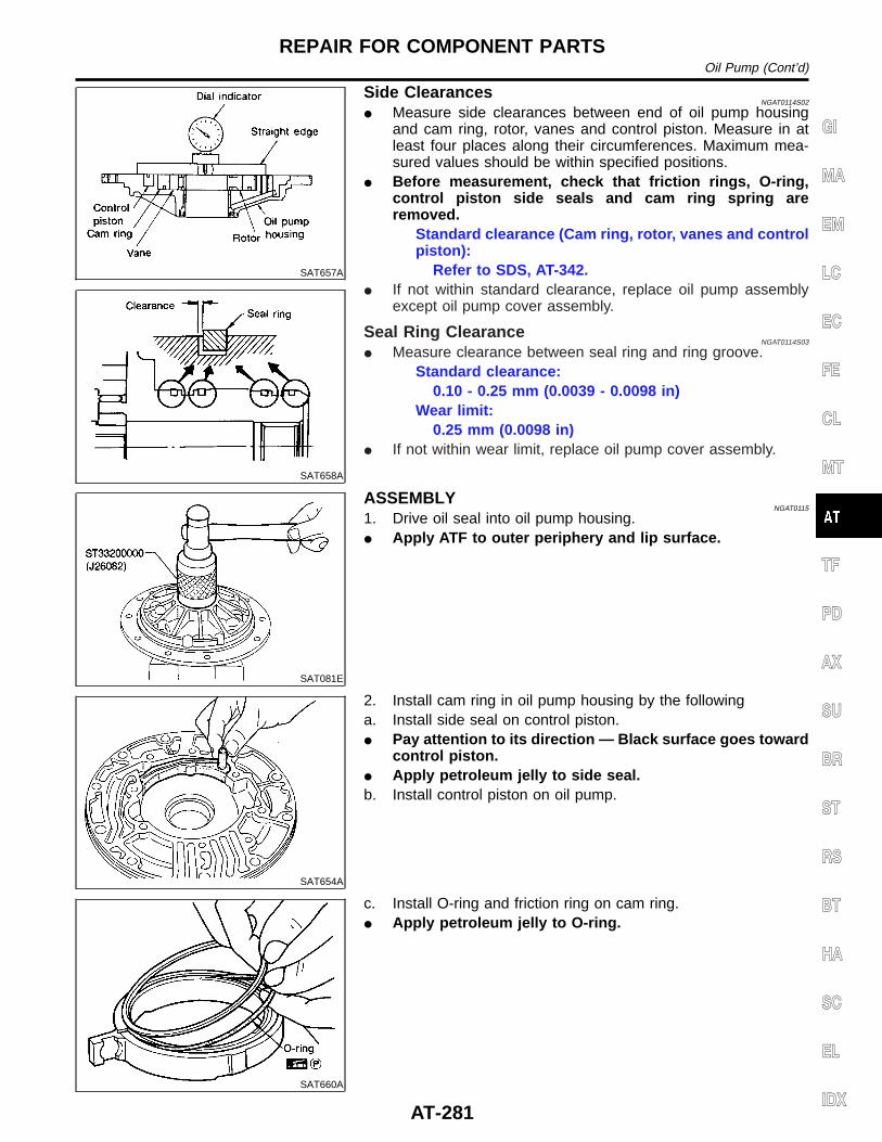
SAT657A
SAT658A
Side ClearancesNGAT0114S02
I Measure side clearances between end of oil pump housingand cam ring, rotor, vanes and control piston. Measure in atleast four places along their circumferences. Maximum mea-sured values should be within specified positions.
I Before measurement, check that friction rings, O-ring,control piston side seals and cam ring spring areremoved.
Standard clearance (Cam ring, rotor, vanes and controlpiston):
Refer to SDS, AT-342.I If not within standard clearance, replace oil pump assembly
except oil pump cover assembly.
Seal Ring ClearanceNGAT0114S03
I Measure clearance between seal ring and ring groove.Standard clearance:
0.10 - 0.25 mm (0.0039 - 0.0098 in)Wear limit:
0.25 mm (0.0098 in)I If not within wear limit, replace oil pump cover assembly.
SAT081E
ASSEMBLYNGAT0115
1. Drive oil seal into oil pump housing.I Apply ATF to outer periphery and lip surface.
SAT654A
2. Install cam ring in oil pump housing by the followinga. Install side seal on control piston.I Pay attention to its direction — Black surface goes toward
control piston.I Apply petroleum jelly to side seal.b. Install control piston on oil pump.
SAT660A
c. Install O-ring and friction ring on cam ring.I Apply petroleum jelly to O-ring.
GI
MA
EM
LC
EC
FE
CL
MT
TF
PD
AX
SU
BR
ST
RS
BT
HA
SC
EL
IDX
REPAIR FOR COMPONENT PARTSOil Pump (Cont’d)
AT-281
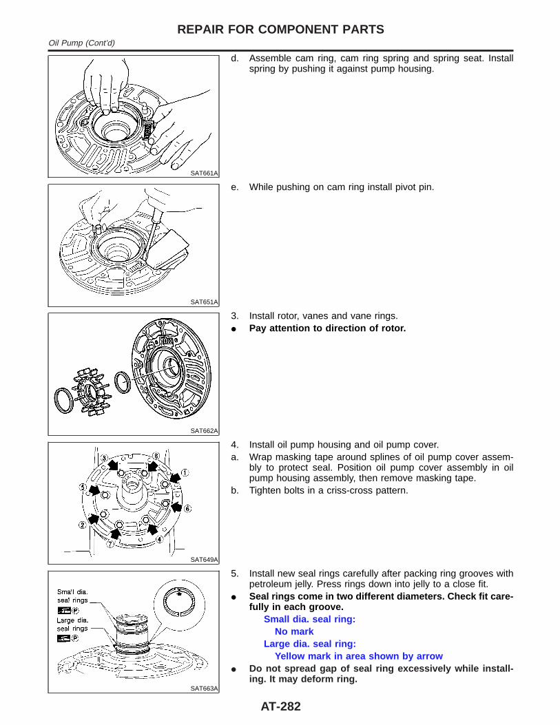
SAT661A
d. Assemble cam ring, cam ring spring and spring seat. Installspring by pushing it against pump housing.
SAT651A
e. While pushing on cam ring install pivot pin.
SAT662A
3. Install rotor, vanes and vane rings.I Pay attention to direction of rotor.
SAT649A
4. Install oil pump housing and oil pump cover.a. Wrap masking tape around splines of oil pump cover assem-
bly to protect seal. Position oil pump cover assembly in oilpump housing assembly, then remove masking tape.
b. Tighten bolts in a criss-cross pattern.
SAT663A
5. Install new seal rings carefully after packing ring grooves withpetroleum jelly. Press rings down into jelly to a close fit.
I Seal rings come in two different diameters. Check fit care-fully in each groove.
Small dia. seal ring:No mark
Large dia. seal ring:Yellow mark in area shown by arrow
I Do not spread gap of seal ring excessively while install-ing. It may deform ring.
REPAIR FOR COMPONENT PARTSOil Pump (Cont’d)
AT-282
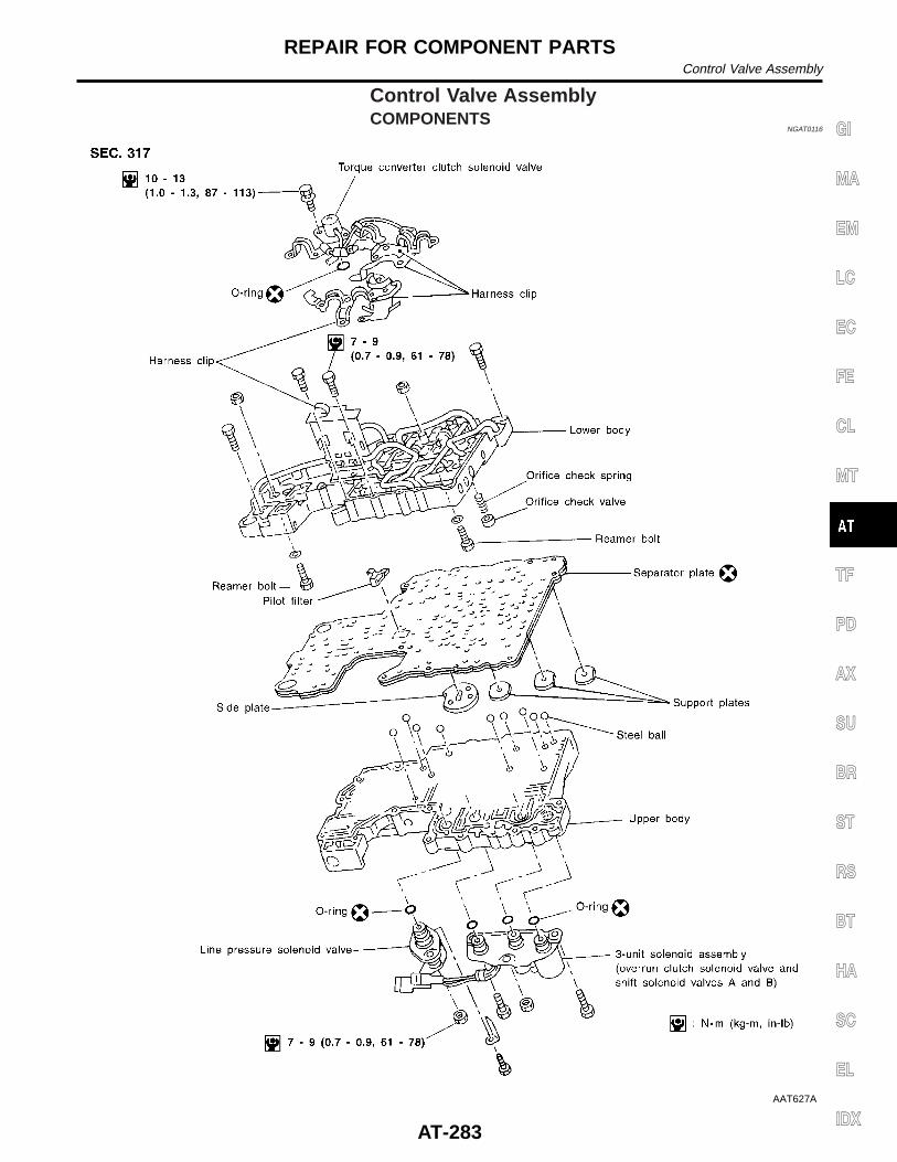
Control Valve AssemblyCOMPONENTS
NGAT0116
AAT627A
GI
MA
EM
LC
EC
FE
CL
MT
TF
PD
AX
SU
BR
ST
RS
BT
HA
SC
EL
IDX
REPAIR FOR COMPONENT PARTSControl Valve Assembly
AT-283
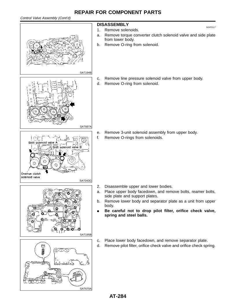
SAT194B
DISASSEMBLYNGAT0117
1. Remove solenoids.a. Remove torque converter clutch solenoid valve and side plate
from lower body.b. Remove O-ring from solenoid.
SAT667A
c. Remove line pressure solenoid valve from upper body.d. Remove O-ring from solenoid.
SAT043G
e. Remove 3-unit solenoid assembly from upper body.f. Remove O-rings from solenoids.
SAT195B
2. Disassemble upper and lower bodies.a. Place upper body facedown, and remove bolts, reamer bolts,
side plate and support plates.b. Remove lower body and separator plate as a unit from upper
body.I Be careful not to drop pilot filter, orifice check valve,
spring and steel balls.
SAT670A
c. Place lower body facedown, and remove separator plate.d. Remove pilot filter, orifice check valve and orifice check spring.
REPAIR FOR COMPONENT PARTSControl Valve Assembly (Cont’d)
AT-284
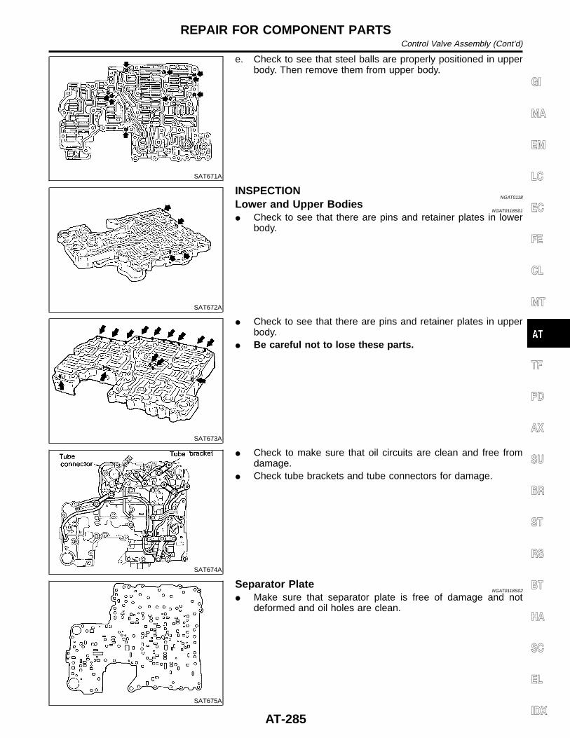
SAT671A
e. Check to see that steel balls are properly positioned in upperbody. Then remove them from upper body.
SAT672A
INSPECTIONNGAT0118
Lower and Upper BodiesNGAT0118S01
I Check to see that there are pins and retainer plates in lowerbody.
SAT673A
I Check to see that there are pins and retainer plates in upperbody.
I Be careful not to lose these parts.
SAT674A
I Check to make sure that oil circuits are clean and free fromdamage.
I Check tube brackets and tube connectors for damage.
SAT675A
Separator PlateNGAT0118S02
I Make sure that separator plate is free of damage and notdeformed and oil holes are clean.
GI
MA
EM
LC
EC
FE
CL
MT
TF
PD
AX
SU
BR
ST
RS
BT
HA
SC
EL
IDX
REPAIR FOR COMPONENT PARTSControl Valve Assembly (Cont’d)
AT-285
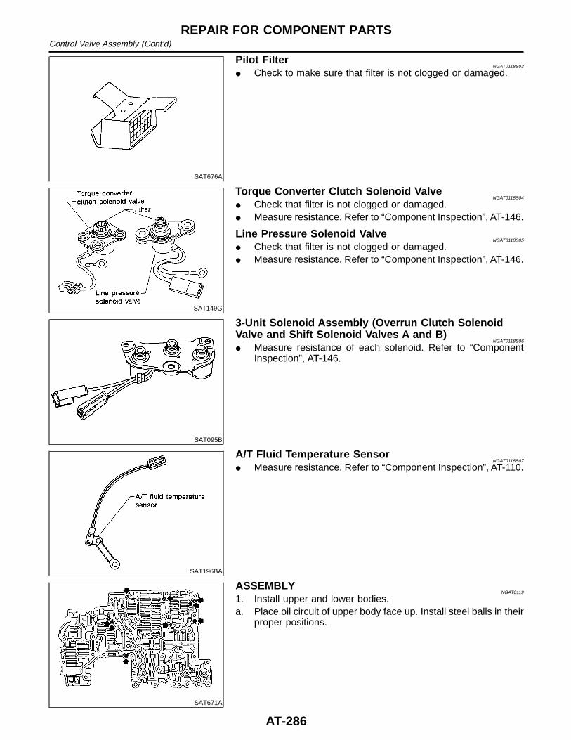
SAT676A
Pilot FilterNGAT0118S03
I Check to make sure that filter is not clogged or damaged.
SAT149G
Torque Converter Clutch Solenoid ValveNGAT0118S04
I Check that filter is not clogged or damaged.I Measure resistance. Refer to “Component Inspection”, AT-146.
Line Pressure Solenoid ValveNGAT0118S05
I Check that filter is not clogged or damaged.I Measure resistance. Refer to “Component Inspection”, AT-146.
SAT095B
3-Unit Solenoid Assembly (Overrun Clutch SolenoidValve and Shift Solenoid Valves A and B)
NGAT0118S06
I Measure resistance of each solenoid. Refer to “ComponentInspection”, AT-146.
SAT196BA
A/T Fluid Temperature SensorNGAT0118S07
I Measure resistance. Refer to “Component Inspection”, AT-110.
SAT671A
ASSEMBLYNGAT0119
1. Install upper and lower bodies.a. Place oil circuit of upper body face up. Install steel balls in their
proper positions.
REPAIR FOR COMPONENT PARTSControl Valve Assembly (Cont’d)
AT-286
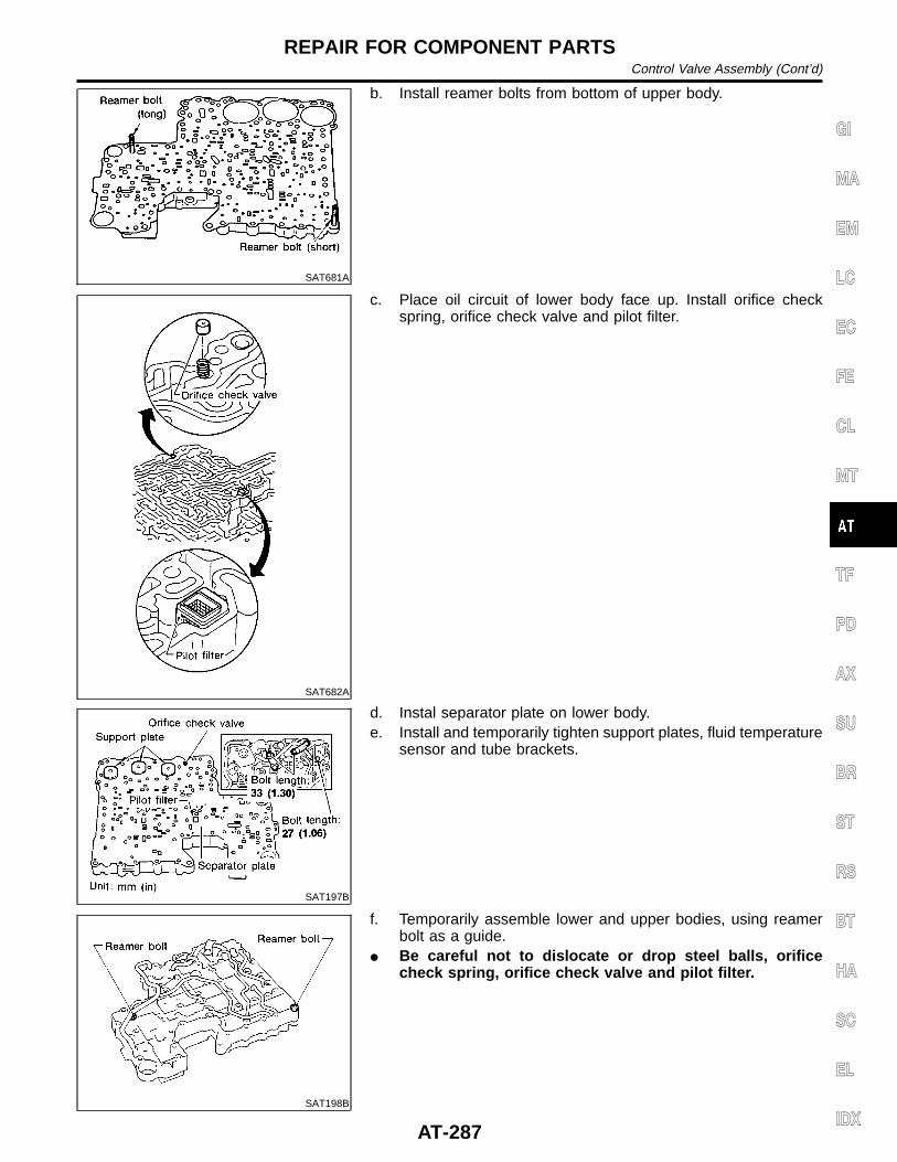
SAT681A
b. Install reamer bolts from bottom of upper body.
SAT682A
c. Place oil circuit of lower body face up. Install orifice checkspring, orifice check valve and pilot filter.
SAT197B
d. Instal separator plate on lower body.e. Install and temporarily tighten support plates, fluid temperature
sensor and tube brackets.
SAT198B
f. Temporarily assemble lower and upper bodies, using reamerbolt as a guide.
I Be careful not to dislocate or drop steel balls, orificecheck spring, orifice check valve and pilot filter.
GI
MA
EM
LC
EC
FE
CL
MT
TF
PD
AX
SU
BR
ST
RS
BT
HA
SC
EL
IDX
REPAIR FOR COMPONENT PARTSControl Valve Assembly (Cont’d)
AT-287
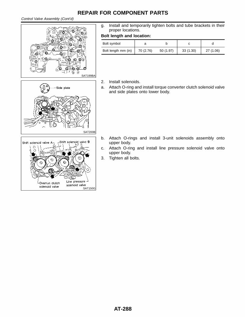
SAT199BA
g. Install and temporarily tighten bolts and tube brackets in theirproper locations.
Bolt length and location:
Bolt symbol a b c d
Bolt length mm (in) 70 (2.76) 50 (1.97) 33 (1.30) 27 (1.06)
SAT200B
2. Install solenoids.a. Attach O-ring and install torque converter clutch solenoid valve
and side plates onto lower body.
SAT150G
b. Attach O-rings and install 3-unit solenoids assembly ontoupper body.
c. Attach O-ring and install line pressure solenoid valve ontoupper body.
3. Tighten all bolts.
REPAIR FOR COMPONENT PARTSControl Valve Assembly (Cont’d)
AT-288
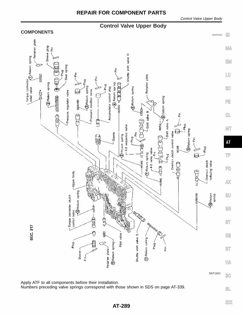
Control Valve Upper BodyCOMPONENTS
NGAT0120
SAT142J
Apply ATF to all components before their installation.Numbers preceding valve springs correspond with those shown in SDS on page AT-339.
GI
MA
EM
LC
EC
FE
CL
MT
TF
PD
AX
SU
BR
ST
RS
BT
HA
SC
EL
IDX
REPAIR FOR COMPONENT PARTSControl Valve Upper Body
AT-289
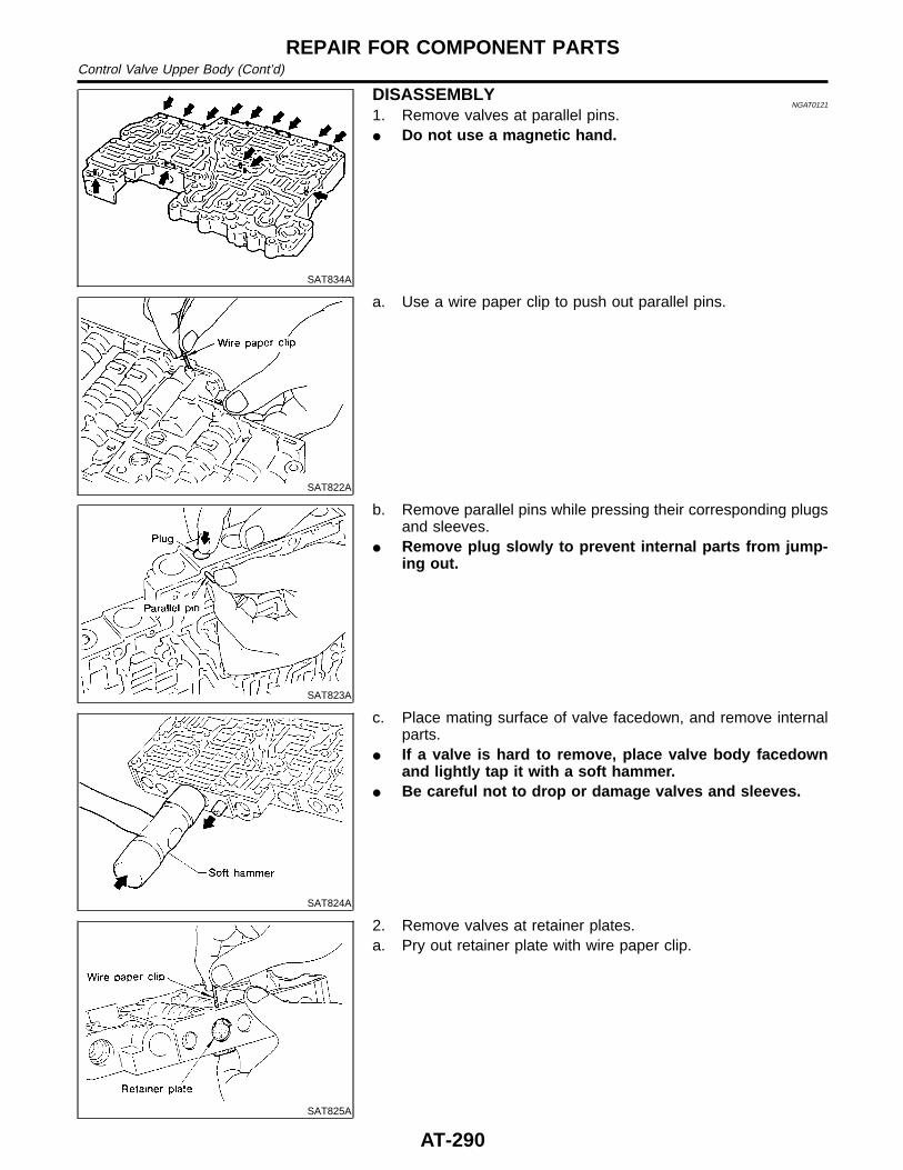
SAT834A
DISASSEMBLYNGAT0121
1. Remove valves at parallel pins.I Do not use a magnetic hand.
SAT822A
a. Use a wire paper clip to push out parallel pins.
SAT823A
b. Remove parallel pins while pressing their corresponding plugsand sleeves.
I Remove plug slowly to prevent internal parts from jump-ing out.
SAT824A
c. Place mating surface of valve facedown, and remove internalparts.
I If a valve is hard to remove, place valve body facedownand lightly tap it with a soft hammer.
I Be careful not to drop or damage valves and sleeves.
SAT825A
2. Remove valves at retainer plates.a. Pry out retainer plate with wire paper clip.
REPAIR FOR COMPONENT PARTSControl Valve Upper Body (Cont’d)
AT-290
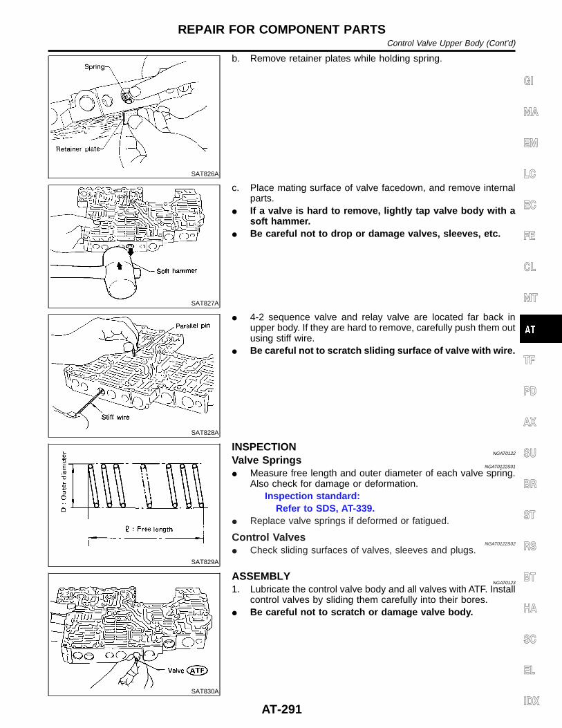
SAT826A
b. Remove retainer plates while holding spring.
SAT827A
c. Place mating surface of valve facedown, and remove internalparts.
I If a valve is hard to remove, lightly tap valve body with asoft hammer.
I Be careful not to drop or damage valves, sleeves, etc.
SAT828A
I 4-2 sequence valve and relay valve are located far back inupper body. If they are hard to remove, carefully push them outusing stiff wire.
I Be careful not to scratch sliding surface of valve with wire.
SAT829A
INSPECTIONNGAT0122
Valve SpringsNGAT0122S01
I Measure free length and outer diameter of each valve spring.Also check for damage or deformation.
Inspection standard:Refer to SDS, AT-339.
I Replace valve springs if deformed or fatigued.
Control ValvesNGAT0122S02
I Check sliding surfaces of valves, sleeves and plugs.
SAT830A
ASSEMBLYNGAT0123
1. Lubricate the control valve body and all valves with ATF. Installcontrol valves by sliding them carefully into their bores.
I Be careful not to scratch or damage valve body.
GI
MA
EM
LC
EC
FE
CL
MT
TF
PD
AX
SU
BR
ST
RS
BT
HA
SC
EL
IDX
REPAIR FOR COMPONENT PARTSControl Valve Upper Body (Cont’d)
AT-291
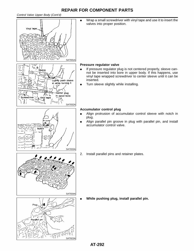
SAT831A
I Wrap a small screwdriver with vinyl tape and use it to insert thevalves into proper position.
SAT832A
Pressure regulator valveI If pressure regulator plug is not centered properly, sleeve can-
not be inserted into bore in upper body. If this happens, usevinyl tape wrapped screwdriver to center sleeve until it can beinserted.
I Turn sleeve slightly while installing.
SAT833A
Accumulator control plugI Align protrusion of accumulator control sleeve with notch in
plug.I Align parallel pin groove in plug with parallel pin, and install
accumulator control valve.
SAT834A
2. Install parallel pins and retainer plates.
SAT823A
I While pushing plug, install parallel pin.
REPAIR FOR COMPONENT PARTSControl Valve Upper Body (Cont’d)
AT-292
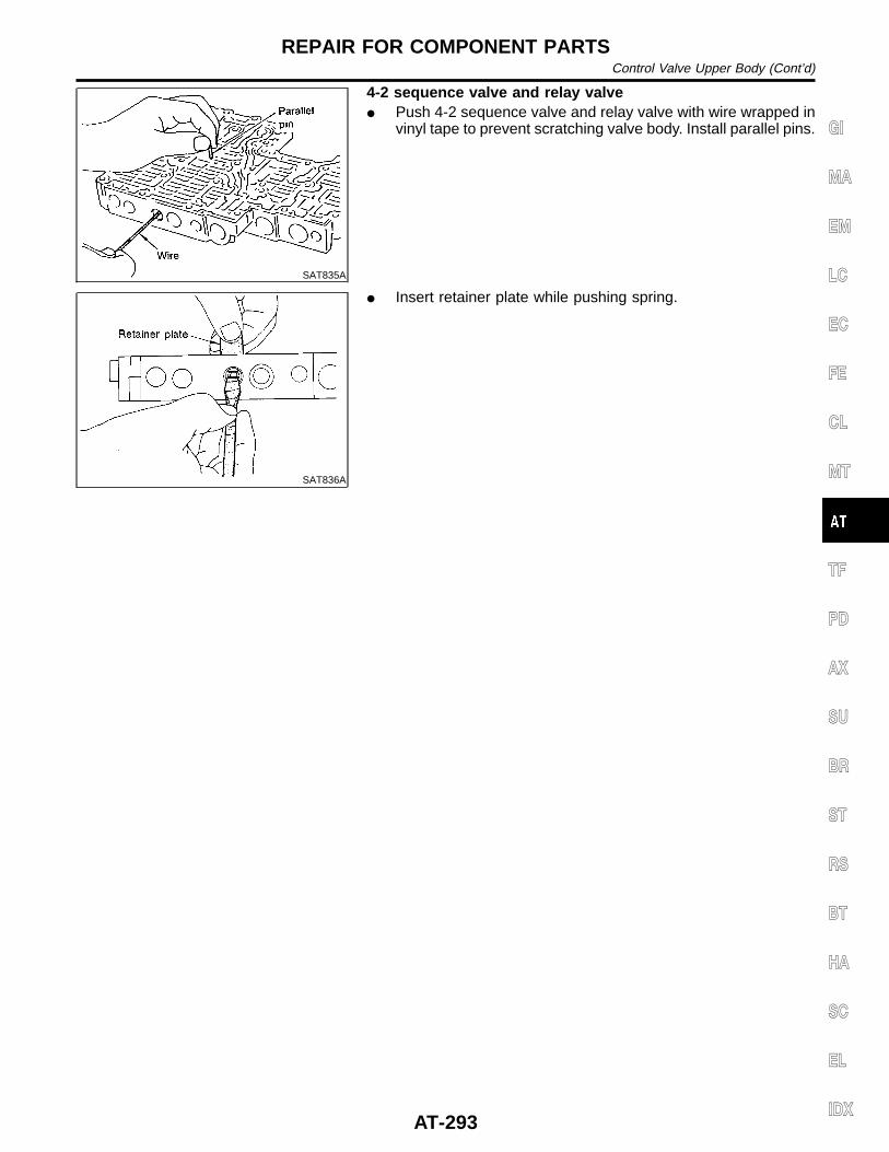
SAT835A
4-2 sequence valve and relay valveI Push 4-2 sequence valve and relay valve with wire wrapped in
vinyl tape to prevent scratching valve body. Install parallel pins.
SAT836A
I Insert retainer plate while pushing spring.
GI
MA
EM
LC
EC
FE
CL
MT
TF
PD
AX
SU
BR
ST
RS
BT
HA
SC
EL
IDX
REPAIR FOR COMPONENT PARTSControl Valve Upper Body (Cont’d)
AT-293
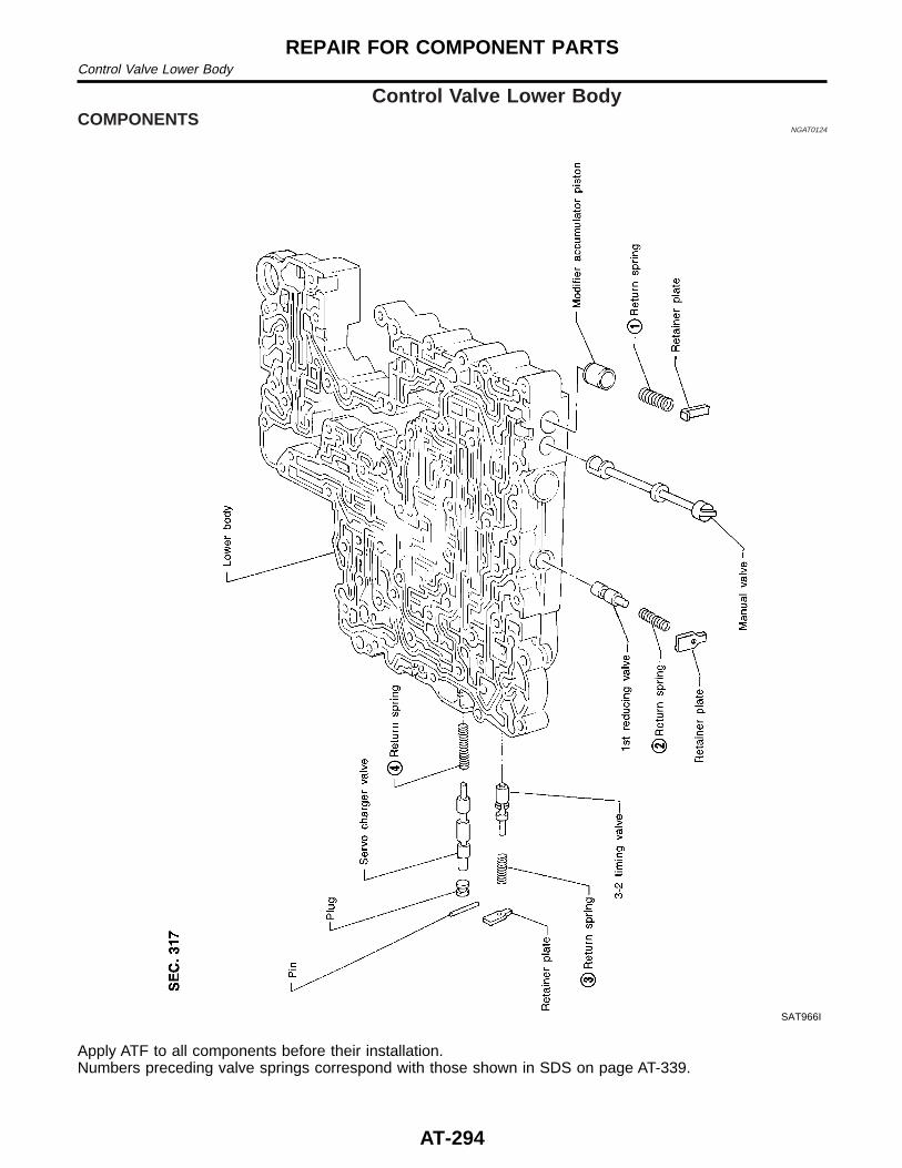
Control Valve Lower BodyCOMPONENTS
NGAT0124
SAT966I
Apply ATF to all components before their installation.Numbers preceding valve springs correspond with those shown in SDS on page AT-339.
REPAIR FOR COMPONENT PARTSControl Valve Lower Body
AT-294
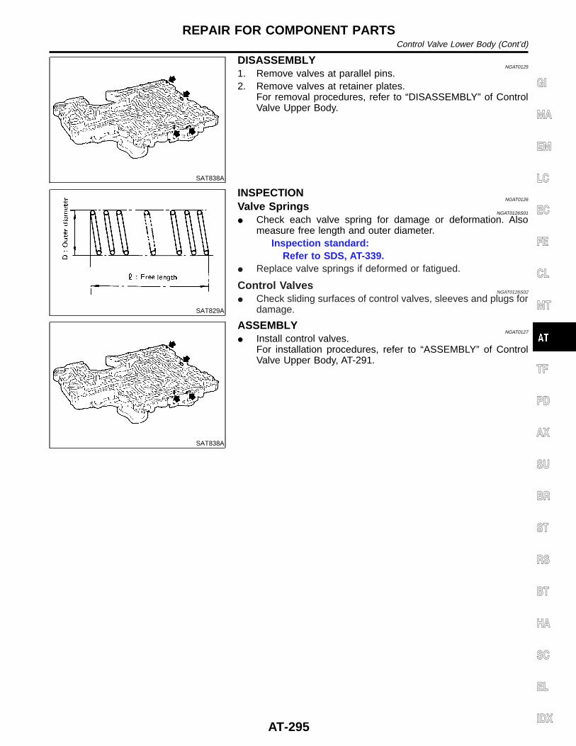
SAT838A
DISASSEMBLYNGAT0125
1. Remove valves at parallel pins.2. Remove valves at retainer plates.
For removal procedures, refer to “DISASSEMBLY” of ControlValve Upper Body.
SAT829A
INSPECTIONNGAT0126
Valve SpringsNGAT0126S01
I Check each valve spring for damage or deformation. Alsomeasure free length and outer diameter.
Inspection standard:Refer to SDS, AT-339.
I Replace valve springs if deformed or fatigued.
Control ValvesNGAT0126S02
I Check sliding surfaces of control valves, sleeves and plugs fordamage.
SAT838A
ASSEMBLYNGAT0127
I Install control valves.For installation procedures, refer to “ASSEMBLY” of ControlValve Upper Body, AT-291.
GI
MA
EM
LC
EC
FE
CL
MT
TF
PD
AX
SU
BR
ST
RS
BT
HA
SC
EL
IDX
REPAIR FOR COMPONENT PARTSControl Valve Lower Body (Cont’d)
AT-295
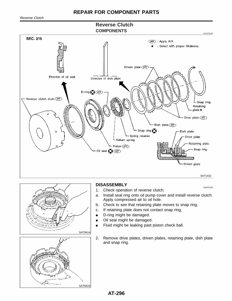
Reverse ClutchCOMPONENTS
NGAT0128
SAT143J
SAT841A
DISASSEMBLYNGAT0129
1. Check operation of reverse clutch.a. Install seal ring onto oil pump cover and install reverse clutch.
Apply compressed air to oil hole.b. Check to see that retaining plate moves to snap ring.c. If retaining plate does not contact snap ring,I D-ring might be damaged.I Oil seal might be damaged.I Fluid might be leaking past piston check ball.
SAT842A
2. Remove drive plates, driven plates, retaining plate, dish plateand snap ring.
REPAIR FOR COMPONENT PARTSReverse Clutch
AT-296
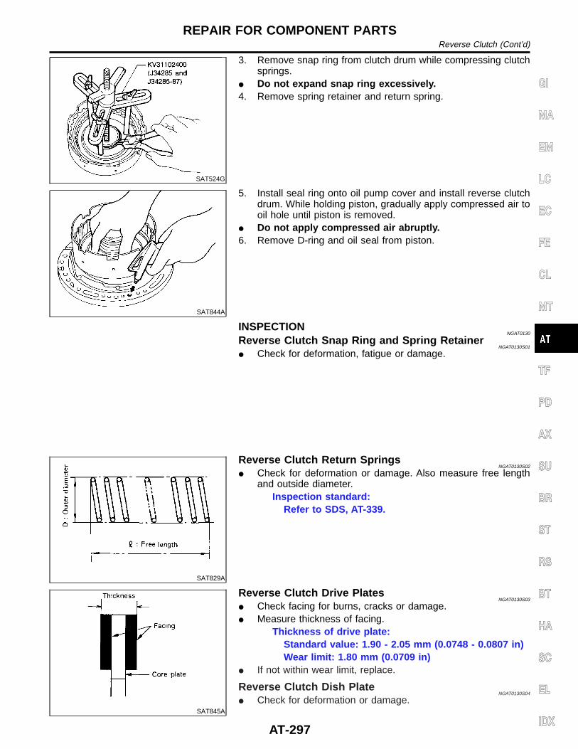
SAT524G
3. Remove snap ring from clutch drum while compressing clutchsprings.
I Do not expand snap ring excessively.4. Remove spring retainer and return spring.
SAT844A
5. Install seal ring onto oil pump cover and install reverse clutchdrum. While holding piston, gradually apply compressed air tooil hole until piston is removed.
I Do not apply compressed air abruptly.6. Remove D-ring and oil seal from piston.
INSPECTIONNGAT0130
Reverse Clutch Snap Ring and Spring RetainerNGAT0130S01
I Check for deformation, fatigue or damage.
SAT829A
Reverse Clutch Return SpringsNGAT0130S02
I Check for deformation or damage. Also measure free lengthand outside diameter.
Inspection standard:Refer to SDS, AT-339.
SAT845A
Reverse Clutch Drive PlatesNGAT0130S03
I Check facing for burns, cracks or damage.I Measure thickness of facing.
Thickness of drive plate:Standard value: 1.90 - 2.05 mm (0.0748 - 0.0807 in)Wear limit: 1.80 mm (0.0709 in)
I If not within wear limit, replace.
Reverse Clutch Dish PlateNGAT0130S04
I Check for deformation or damage.
GI
MA
EM
LC
EC
FE
CL
MT
TF
PD
AX
SU
BR
ST
RS
BT
HA
SC
EL
IDX
REPAIR FOR COMPONENT PARTSReverse Clutch (Cont’d)
AT-297
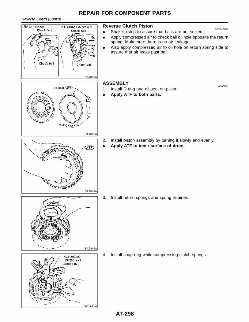
SAT846A
Reverse Clutch PistonNGAT0130S05
I Shake piston to assure that balls are not seized.I Apply compressed air to check ball oil hole opposite the return
spring. Make sure there is no air leakage.I Also apply compressed air to oil hole on return spring side to
assure that air leaks past ball.
SAT847A
ASSEMBLYNGAT0131
1. Install D-ring and oil seal on piston.I Apply ATF to both parts.
SAT848A
2. Install piston assembly by turning it slowly and evenly.I Apply ATF to inner surface of drum.
SAT849A
3. Install return springs and spring retainer.
SAT524G
4. Install snap ring while compressing clutch springs.
REPAIR FOR COMPONENT PARTSReverse Clutch (Cont’d)
AT-298
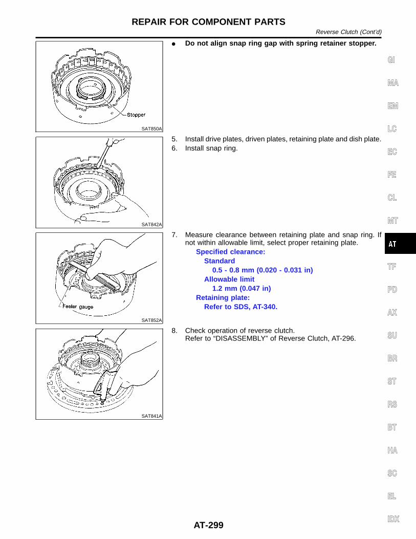
SAT850A
I Do not align snap ring gap with spring retainer stopper.
SAT842A
5. Install drive plates, driven plates, retaining plate and dish plate.6. Install snap ring.
SAT852A
7. Measure clearance between retaining plate and snap ring. Ifnot within allowable limit, select proper retaining plate.
Specified clearance:Standard
0.5 - 0.8 mm (0.020 - 0.031 in)Allowable limit
1.2 mm (0.047 in)Retaining plate:
Refer to SDS, AT-340.
SAT841A
8. Check operation of reverse clutch.Refer to “DISASSEMBLY” of Reverse Clutch, AT-296.
GI
MA
EM
LC
EC
FE
CL
MT
TF
PD
AX
SU
BR
ST
RS
BT
HA
SC
EL
IDX
REPAIR FOR COMPONENT PARTSReverse Clutch (Cont’d)
AT-299
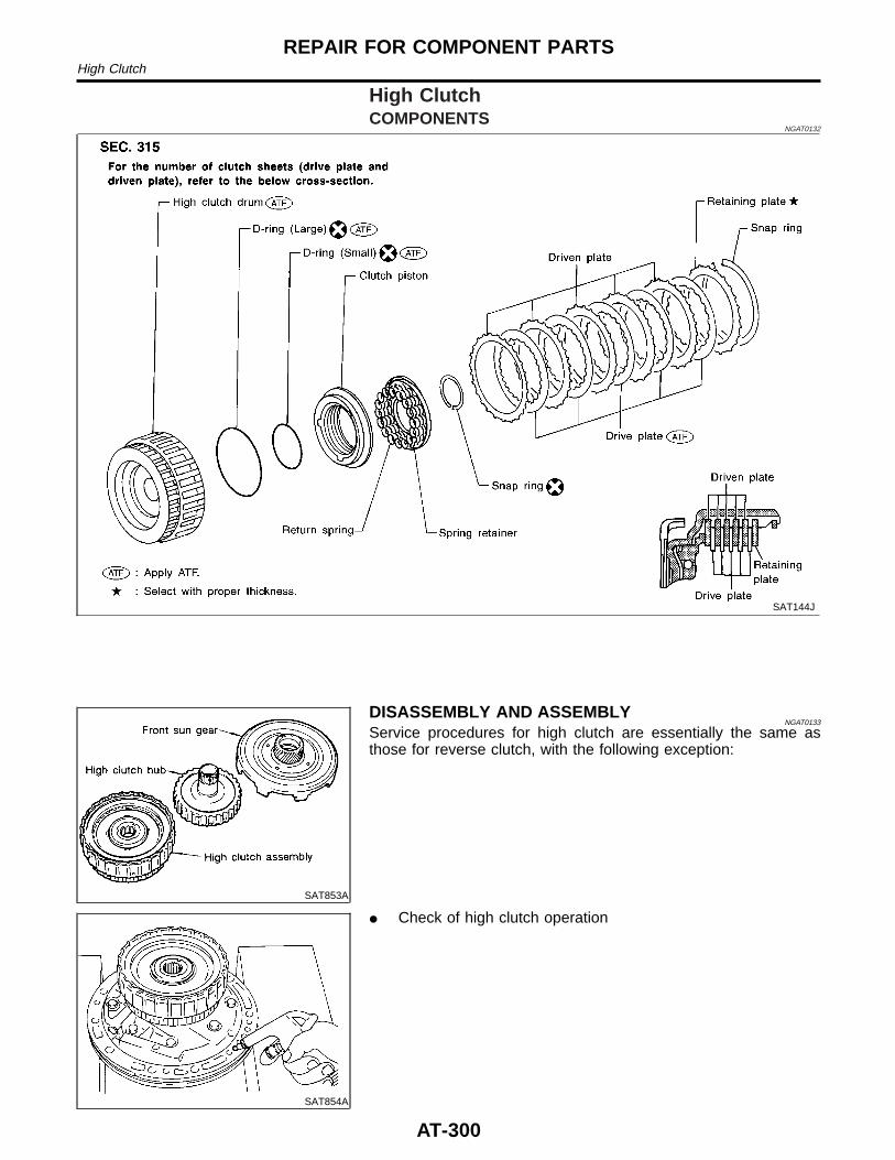
High ClutchCOMPONENTS
NGAT0132
SAT144J
SAT853A
DISASSEMBLY AND ASSEMBLYNGAT0133
Service procedures for high clutch are essentially the same asthose for reverse clutch, with the following exception:
SAT854A
I Check of high clutch operation
REPAIR FOR COMPONENT PARTSHigh Clutch
AT-300
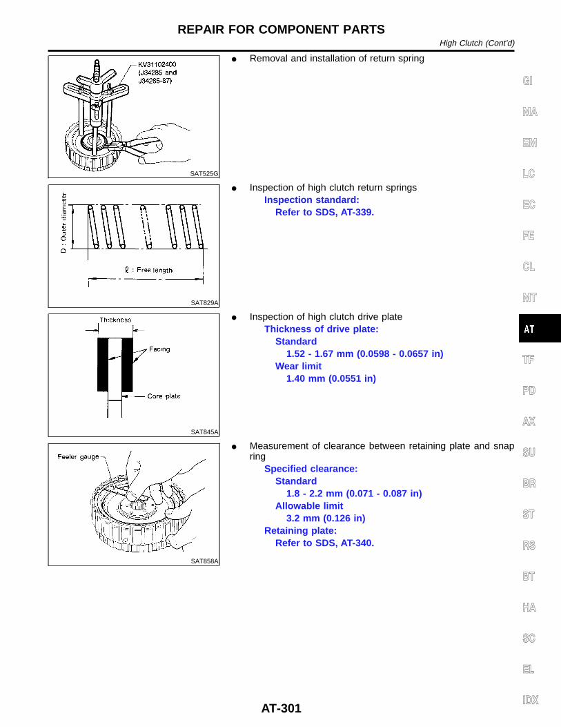
SAT525G
I Removal and installation of return spring
SAT829A
I Inspection of high clutch return springsInspection standard:
Refer to SDS, AT-339.
SAT845A
I Inspection of high clutch drive plateThickness of drive plate:
Standard1.52 - 1.67 mm (0.0598 - 0.0657 in)
Wear limit1.40 mm (0.0551 in)
SAT858A
I Measurement of clearance between retaining plate and snapring
Specified clearance:Standard
1.8 - 2.2 mm (0.071 - 0.087 in)Allowable limit
3.2 mm (0.126 in)Retaining plate:
Refer to SDS, AT-340.
GI
MA
EM
LC
EC
FE
CL
MT
TF
PD
AX
SU
BR
ST
RS
BT
HA
SC
EL
IDX
REPAIR FOR COMPONENT PARTSHigh Clutch (Cont’d)
AT-301
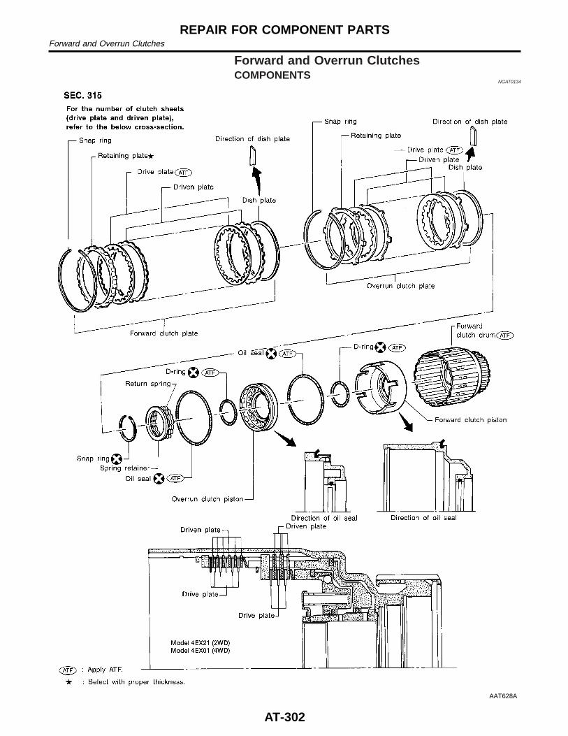
Forward and Overrun ClutchesCOMPONENTS
NGAT0134
AAT628A
REPAIR FOR COMPONENT PARTSForward and Overrun Clutches
AT-302
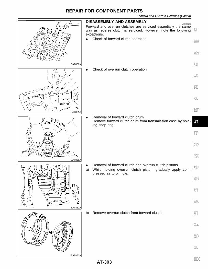
SAT860A
DISASSEMBLY AND ASSEMBLYNGAT0135
Forward and overrun clutches are serviced essentially the sameway as reverse clutch is serviced. However, note the followingexceptions.I Check of forward clutch operation
SAT861A
I Check of overrun clutch operation
SAT865A
I Removal of forward clutch drumRemove forward clutch drum from transmission case by hold-ing snap ring.
SAT862A
I Removal of forward clutch and overrun clutch pistonsa) While holding overrun clutch piston, gradually apply com-
pressed air to oil hole.
SAT863A
b) Remove overrun clutch from forward clutch.
GI
MA
EM
LC
EC
FE
CL
MT
TF
PD
AX
SU
BR
ST
RS
BT
HA
SC
EL
IDX
REPAIR FOR COMPONENT PARTSForward and Overrun Clutches (Cont’d)
AT-303
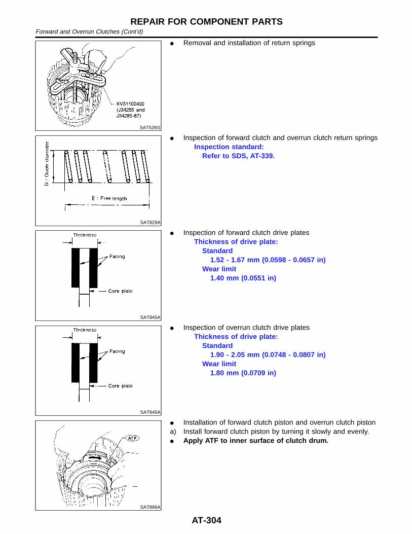
SAT526G
I Removal and installation of return springs
SAT829A
I Inspection of forward clutch and overrun clutch return springsInspection standard:
Refer to SDS, AT-339.
SAT845A
I Inspection of forward clutch drive platesThickness of drive plate:
Standard1.52 - 1.67 mm (0.0598 - 0.0657 in)
Wear limit1.40 mm (0.0551 in)
SAT845A
I Inspection of overrun clutch drive platesThickness of drive plate:
Standard1.90 - 2.05 mm (0.0748 - 0.0807 in)
Wear limit1.80 mm (0.0709 in)
SAT866A
I Installation of forward clutch piston and overrun clutch pistona) Install forward clutch piston by turning it slowly and evenly.I Apply ATF to inner surface of clutch drum.
REPAIR FOR COMPONENT PARTSForward and Overrun Clutches (Cont’d)
AT-304
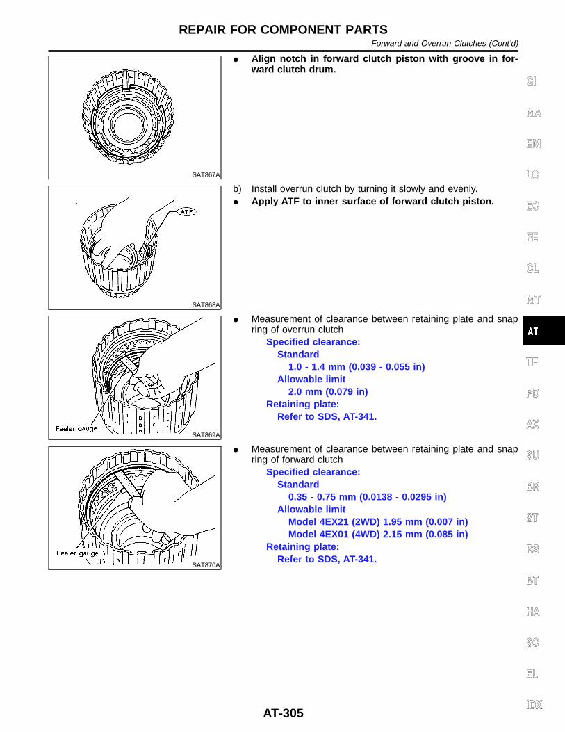
SAT867A
I Align notch in forward clutch piston with groove in for-ward clutch drum.
SAT868A
b) Install overrun clutch by turning it slowly and evenly.I Apply ATF to inner surface of forward clutch piston.
SAT869A
I Measurement of clearance between retaining plate and snapring of overrun clutch
Specified clearance:Standard
1.0 - 1.4 mm (0.039 - 0.055 in)Allowable limit
2.0 mm (0.079 in)Retaining plate:
Refer to SDS, AT-341.
SAT870A
I Measurement of clearance between retaining plate and snapring of forward clutch
Specified clearance:Standard
0.35 - 0.75 mm (0.0138 - 0.0295 in)Allowable limit
Model 4EX21 (2WD) 1.95 mm (0.007 in)Model 4EX01 (4WD) 2.15 mm (0.085 in)
Retaining plate:Refer to SDS, AT-341.
GI
MA
EM
LC
EC
FE
CL
MT
TF
PD
AX
SU
BR
ST
RS
BT
HA
SC
EL
IDX
REPAIR FOR COMPONENT PARTSForward and Overrun Clutches (Cont’d)
AT-305
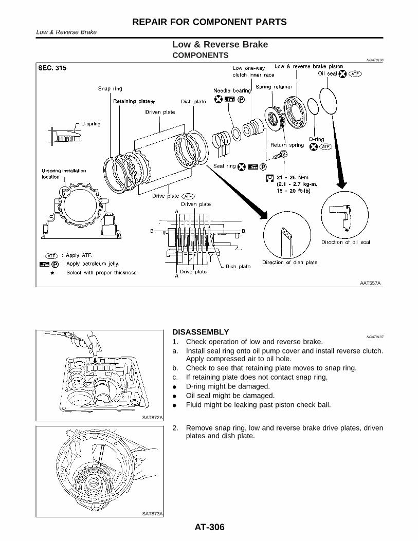
Low & Reverse BrakeCOMPONENTS
NGAT0136
AAT557A
SAT872A
DISASSEMBLYNGAT0137
1. Check operation of low and reverse brake.a. Install seal ring onto oil pump cover and install reverse clutch.
Apply compressed air to oil hole.b. Check to see that retaining plate moves to snap ring.c. If retaining plate does not contact snap ring,I D-ring might be damaged.I Oil seal might be damaged.I Fluid might be leaking past piston check ball.
SAT873A
2. Remove snap ring, low and reverse brake drive plates, drivenplates and dish plate.
REPAIR FOR COMPONENT PARTSLow & Reverse Brake
AT-306

SAT382I
3. Remove low one-way clutch inner race, spring retainer andreturn spring from transmission case.
4. Remove seal rings from low one-way clutch inner race.5. Remove needle bearing from low one-way clutch inner race.
SAT876A
6. Remove low and reverse brake piston using compressed air.7. Remove oil seal and D-ring from piston.
INSPECTIONNGAT0138
Low and Reverse Brake Snap Ring and Spring RetainerNGAT0138S01
I Check for deformation, or damage.
SAT829A
Low and Reverse Brake Return SpringsNGAT0138S02
I Check for deformation or damage. Also measure free lengthand outside diameter.
Inspection standard:Refer to SDS, AT-339.
SAT845A
Low and Reverse Brake Drive PlatesNGAT0138S03
I Check facing for burns, cracks or damage.I Measure thickness of facing.
Thickness of drive plate:Standard value
1.52 - 1.67 mm (0.0598 - 0.0657 in)Wear limit
1.40 mm (0.0551 in)I If not within wear limit, replace.
GI
MA
EM
LC
EC
FE
CL
MT
TF
PD
AX
SU
BR
ST
RS
BT
HA
SC
EL
IDX
REPAIR FOR COMPONENT PARTSLow & Reverse Brake (Cont’d)
AT-307
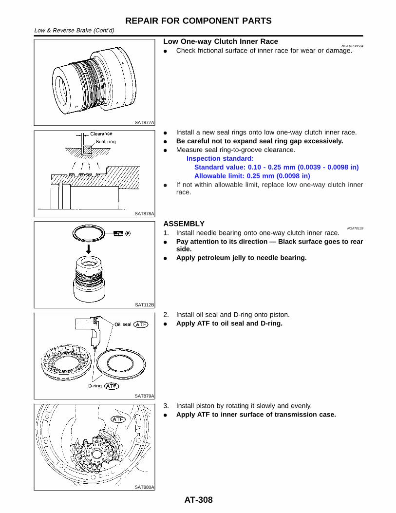
SAT877A
Low One-way Clutch Inner RaceNGAT0138S04
I Check frictional surface of inner race for wear or damage.
SAT878A
I Install a new seal rings onto low one-way clutch inner race.I Be careful not to expand seal ring gap excessively.I Measure seal ring-to-groove clearance.
Inspection standard:Standard value: 0.10 - 0.25 mm (0.0039 - 0.0098 in)Allowable limit: 0.25 mm (0.0098 in)
I If not within allowable limit, replace low one-way clutch innerrace.
SAT112B
ASSEMBLYNGAT0139
1. Install needle bearing onto one-way clutch inner race.I Pay attention to its direction — Black surface goes to rear
side.I Apply petroleum jelly to needle bearing.
SAT879A
2. Install oil seal and D-ring onto piston.I Apply ATF to oil seal and D-ring.
SAT880A
3. Install piston by rotating it slowly and evenly.I Apply ATF to inner surface of transmission case.
REPAIR FOR COMPONENT PARTSLow & Reverse Brake (Cont’d)
AT-308
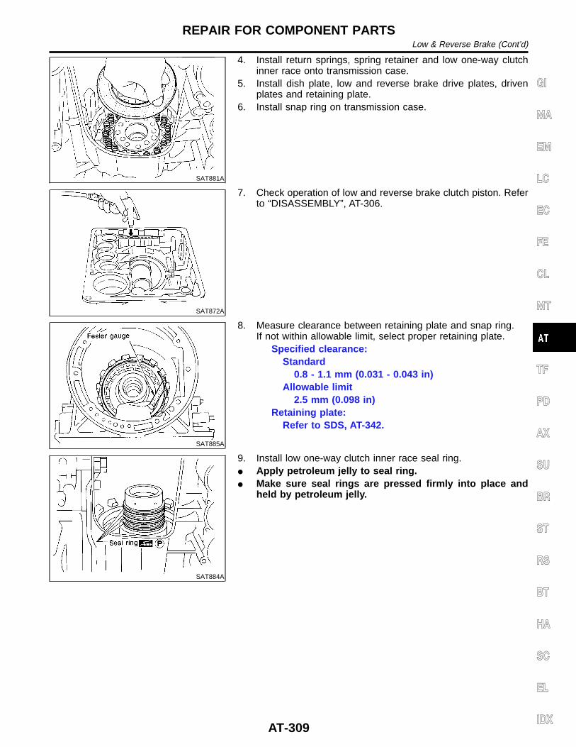
SAT881A
4. Install return springs, spring retainer and low one-way clutchinner race onto transmission case.
5. Install dish plate, low and reverse brake drive plates, drivenplates and retaining plate.
6. Install snap ring on transmission case.
SAT872A
7. Check operation of low and reverse brake clutch piston. Referto “DISASSEMBLY”, AT-306.
SAT885A
8. Measure clearance between retaining plate and snap ring.If not within allowable limit, select proper retaining plate.
Specified clearance:Standard
0.8 - 1.1 mm (0.031 - 0.043 in)Allowable limit
2.5 mm (0.098 in)Retaining plate:
Refer to SDS, AT-342.
SAT884A
9. Install low one-way clutch inner race seal ring.I Apply petroleum jelly to seal ring.I Make sure seal rings are pressed firmly into place and
held by petroleum jelly.
GI
MA
EM
LC
EC
FE
CL
MT
TF
PD
AX
SU
BR
ST
RS
BT
HA
SC
EL
IDX
REPAIR FOR COMPONENT PARTSLow & Reverse Brake (Cont’d)
AT-309
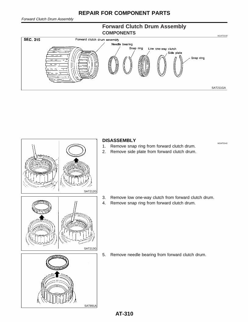
Forward Clutch Drum AssemblyCOMPONENTS
NGAT0140
SAT211GA
SAT212G
DISASSEMBLYNGAT0141
1. Remove snap ring from forward clutch drum.2. Remove side plate from forward clutch drum.
SAT213G
3. Remove low one-way clutch from forward clutch drum.4. Remove snap ring from forward clutch drum.
SAT891A
5. Remove needle bearing from forward clutch drum.
REPAIR FOR COMPONENT PARTSForward Clutch Drum Assembly
AT-310
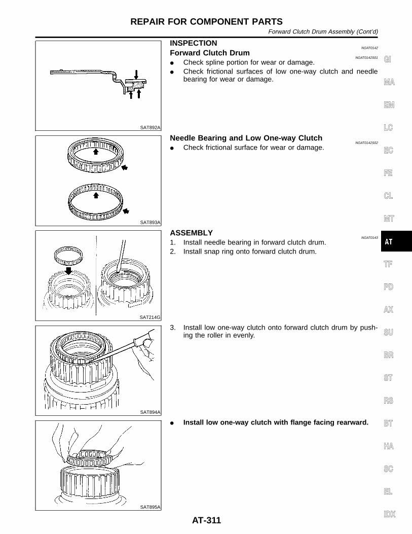
SAT892A
INSPECTIONNGAT0142
Forward Clutch DrumNGAT0142S01
I Check spline portion for wear or damage.I Check frictional surfaces of low one-way clutch and needle
bearing for wear or damage.
SAT893A
Needle Bearing and Low One-way ClutchNGAT0142S02
I Check frictional surface for wear or damage.
SAT214G
ASSEMBLYNGAT0143
1. Install needle bearing in forward clutch drum.2. Install snap ring onto forward clutch drum.
SAT894A
3. Install low one-way clutch onto forward clutch drum by push-ing the roller in evenly.
SAT895A
I Install low one-way clutch with flange facing rearward.
GI
MA
EM
LC
EC
FE
CL
MT
TF
PD
AX
SU
BR
ST
RS
BT
HA
SC
EL
IDX
REPAIR FOR COMPONENT PARTSForward Clutch Drum Assembly (Cont’d)
AT-311
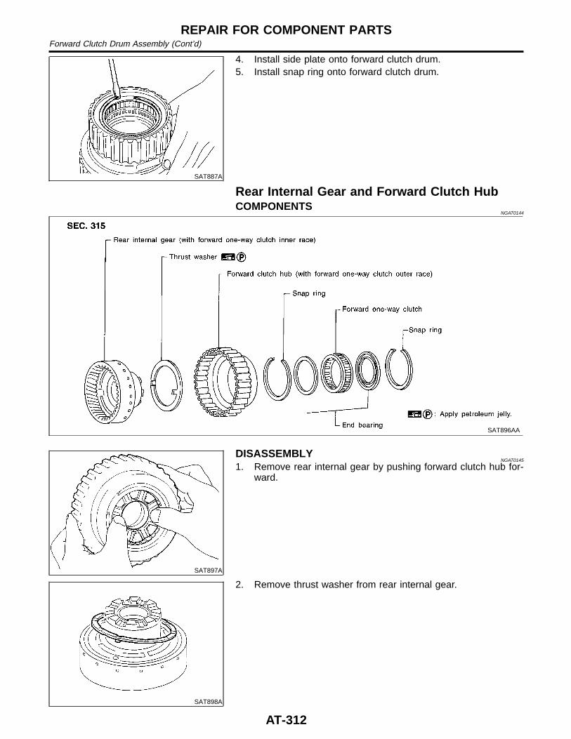
SAT887A
4. Install side plate onto forward clutch drum.5. Install snap ring onto forward clutch drum.
Rear Internal Gear and Forward Clutch HubCOMPONENTS
NGAT0144
SAT896AA
SAT897A
DISASSEMBLYNGAT0145
1. Remove rear internal gear by pushing forward clutch hub for-ward.
SAT898A
2. Remove thrust washer from rear internal gear.
REPAIR FOR COMPONENT PARTSForward Clutch Drum Assembly (Cont’d)
AT-312
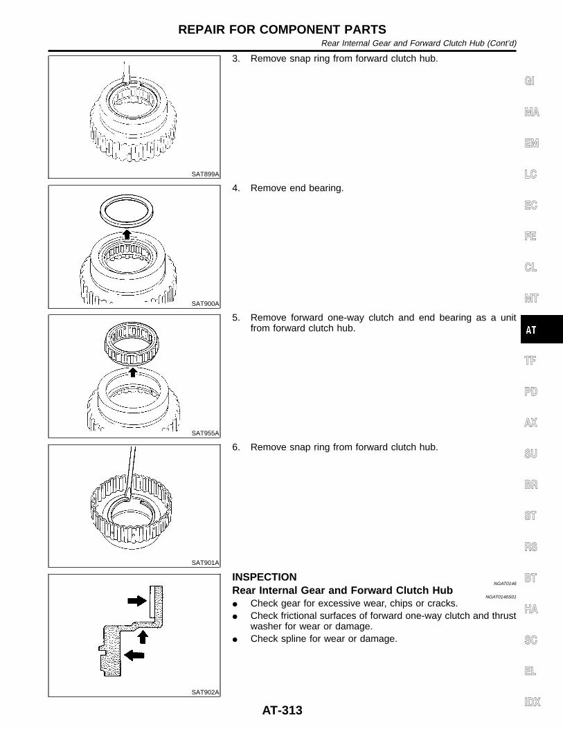
SAT899A
3. Remove snap ring from forward clutch hub.
SAT900A
4. Remove end bearing.
SAT955A
5. Remove forward one-way clutch and end bearing as a unitfrom forward clutch hub.
SAT901A
6. Remove snap ring from forward clutch hub.
SAT902A
INSPECTIONNGAT0146
Rear Internal Gear and Forward Clutch HubNGAT0146S01
I Check gear for excessive wear, chips or cracks.I Check frictional surfaces of forward one-way clutch and thrust
washer for wear or damage.I Check spline for wear or damage.
GI
MA
EM
LC
EC
FE
CL
MT
TF
PD
AX
SU
BR
ST
RS
BT
HA
SC
EL
IDX
REPAIR FOR COMPONENT PARTSRear Internal Gear and Forward Clutch Hub (Cont’d)
AT-313
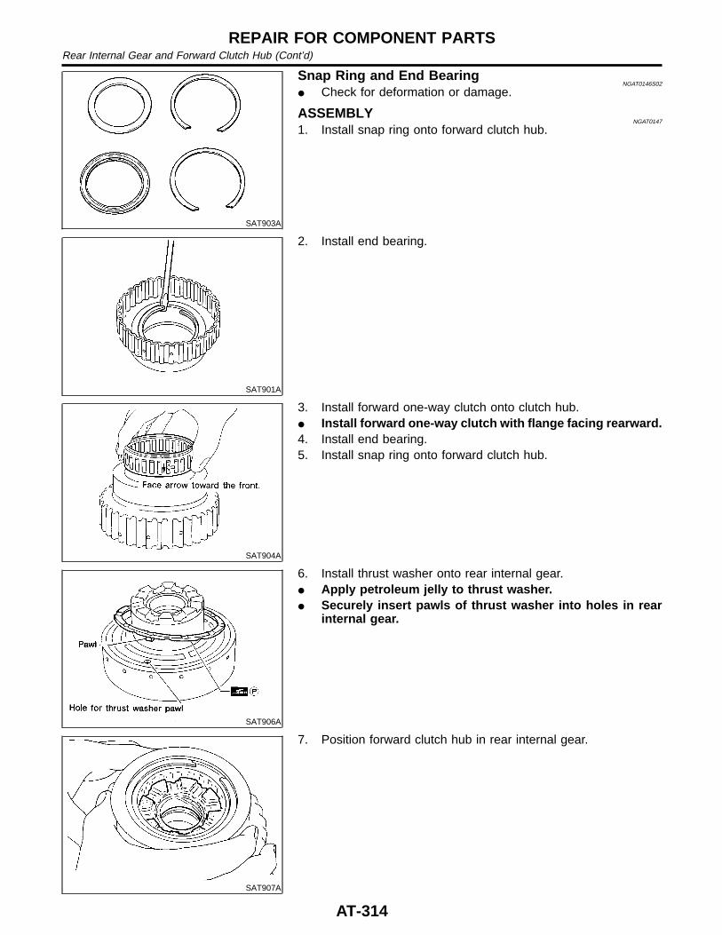
SAT903A
Snap Ring and End BearingNGAT0146S02
I Check for deformation or damage.
ASSEMBLYNGAT0147
1. Install snap ring onto forward clutch hub.
SAT901A
2. Install end bearing.
SAT904A
3. Install forward one-way clutch onto clutch hub.I Install forward one-way clutch with flange facing rearward.4. Install end bearing.5. Install snap ring onto forward clutch hub.
SAT906A
6. Install thrust washer onto rear internal gear.I Apply petroleum jelly to thrust washer.I Securely insert pawls of thrust washer into holes in rear
internal gear.
SAT907A
7. Position forward clutch hub in rear internal gear.
REPAIR FOR COMPONENT PARTSRear Internal Gear and Forward Clutch Hub (Cont’d)
AT-314
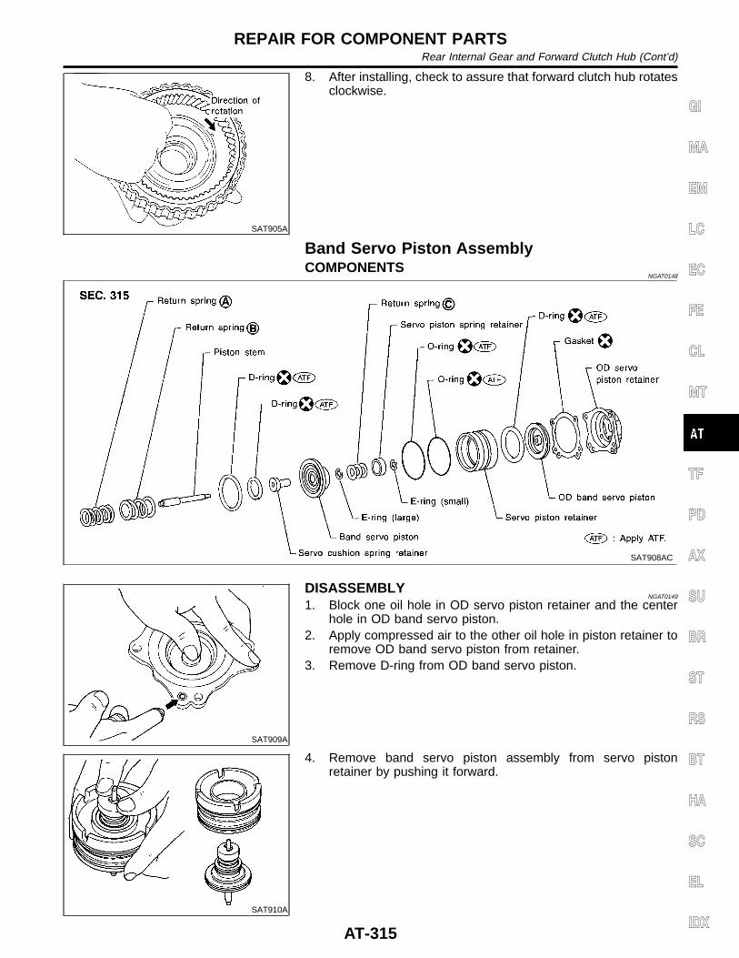
SAT905A
8. After installing, check to assure that forward clutch hub rotatesclockwise.
Band Servo Piston AssemblyCOMPONENTS
NGAT0148
SAT908AC
SAT909A
DISASSEMBLYNGAT0149
1. Block one oil hole in OD servo piston retainer and the centerhole in OD band servo piston.
2. Apply compressed air to the other oil hole in piston retainer toremove OD band servo piston from retainer.
3. Remove D-ring from OD band servo piston.
SAT910A
4. Remove band servo piston assembly from servo pistonretainer by pushing it forward.
GI
MA
EM
LC
EC
FE
CL
MT
TF
PD
AX
SU
BR
ST
RS
BT
HA
SC
EL
IDX
REPAIR FOR COMPONENT PARTSRear Internal Gear and Forward Clutch Hub (Cont’d)
AT-315
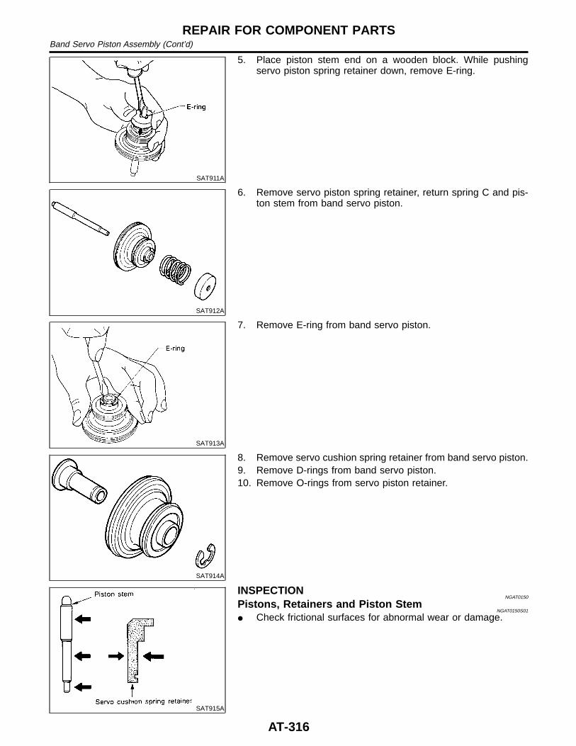
SAT911A
5. Place piston stem end on a wooden block. While pushingservo piston spring retainer down, remove E-ring.
SAT912A
6. Remove servo piston spring retainer, return spring C and pis-ton stem from band servo piston.
SAT913A
7. Remove E-ring from band servo piston.
SAT914A
8. Remove servo cushion spring retainer from band servo piston.9. Remove D-rings from band servo piston.10. Remove O-rings from servo piston retainer.
SAT915A
INSPECTIONNGAT0150
Pistons, Retainers and Piston StemNGAT0150S01
I Check frictional surfaces for abnormal wear or damage.
REPAIR FOR COMPONENT PARTSBand Servo Piston Assembly (Cont’d)
AT-316
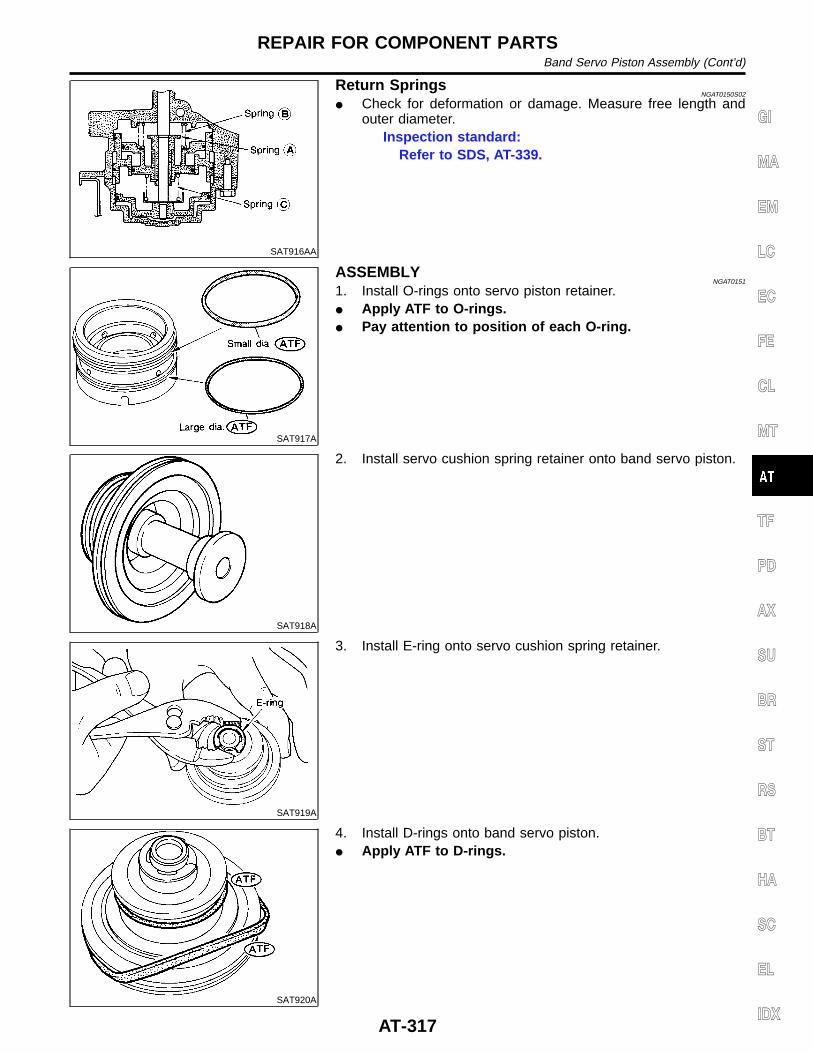
SAT916AA
Return SpringsNGAT0150S02
I Check for deformation or damage. Measure free length andouter diameter.
Inspection standard:Refer to SDS, AT-339.
SAT917A
ASSEMBLYNGAT0151
1. Install O-rings onto servo piston retainer.I Apply ATF to O-rings.I Pay attention to position of each O-ring.
SAT918A
2. Install servo cushion spring retainer onto band servo piston.
SAT919A
3. Install E-ring onto servo cushion spring retainer.
SAT920A
4. Install D-rings onto band servo piston.I Apply ATF to D-rings.
GI
MA
EM
LC
EC
FE
CL
MT
TF
PD
AX
SU
BR
ST
RS
BT
HA
SC
EL
IDX
REPAIR FOR COMPONENT PARTSBand Servo Piston Assembly (Cont’d)
AT-317
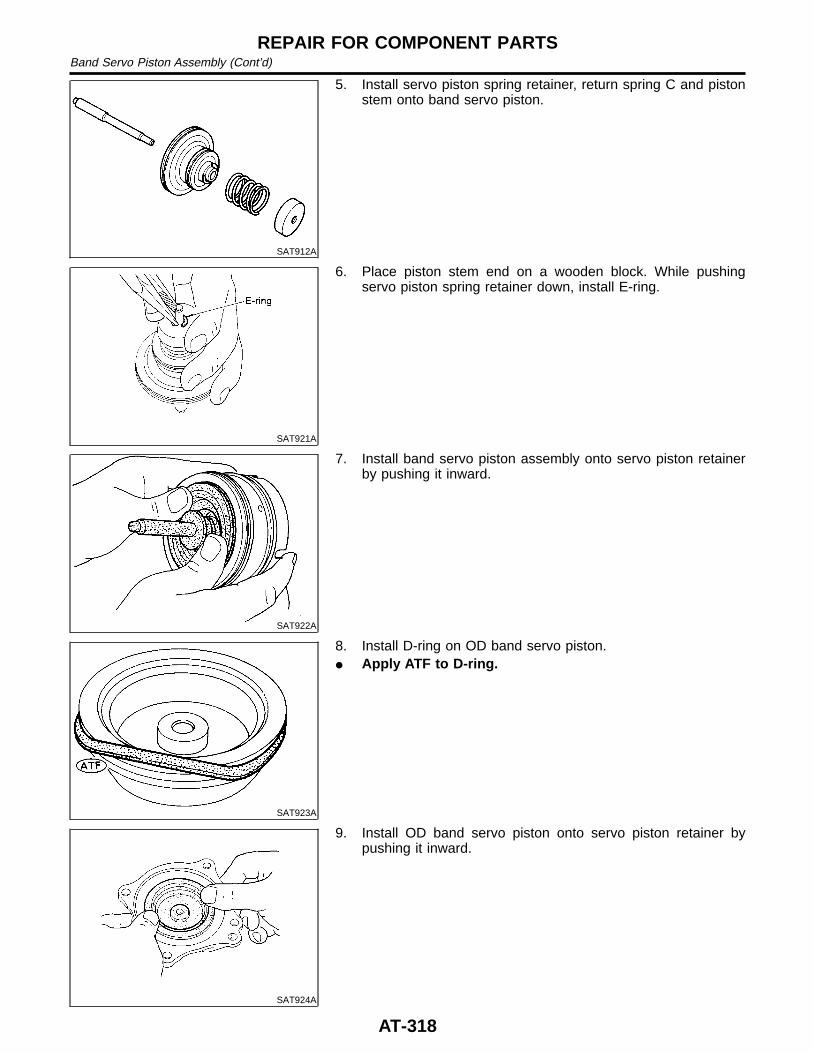
SAT912A
5. Install servo piston spring retainer, return spring C and pistonstem onto band servo piston.
SAT921A
6. Place piston stem end on a wooden block. While pushingservo piston spring retainer down, install E-ring.
SAT922A
7. Install band servo piston assembly onto servo piston retainerby pushing it inward.
SAT923A
8. Install D-ring on OD band servo piston.I Apply ATF to D-ring.
SAT924A
9. Install OD band servo piston onto servo piston retainer bypushing it inward.
REPAIR FOR COMPONENT PARTSBand Servo Piston Assembly (Cont’d)
AT-318
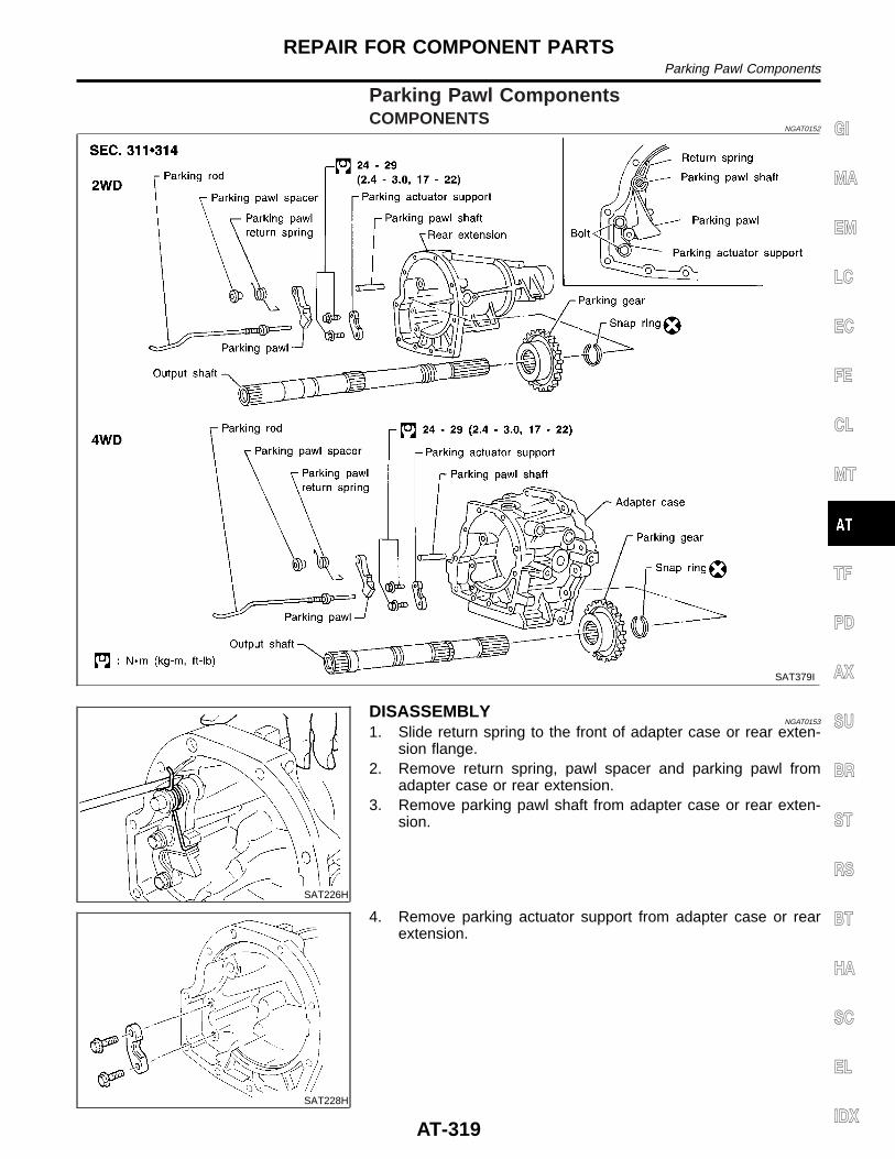
Parking Pawl ComponentsCOMPONENTS
NGAT0152
SAT379I
SAT226H
DISASSEMBLYNGAT0153
1. Slide return spring to the front of adapter case or rear exten-sion flange.
2. Remove return spring, pawl spacer and parking pawl fromadapter case or rear extension.
3. Remove parking pawl shaft from adapter case or rear exten-sion.
SAT228H
4. Remove parking actuator support from adapter case or rearextension.
GI
MA
EM
LC
EC
FE
CL
MT
TF
PD
AX
SU
BR
ST
RS
BT
HA
SC
EL
IDX
REPAIR FOR COMPONENT PARTSParking Pawl Components
AT-319
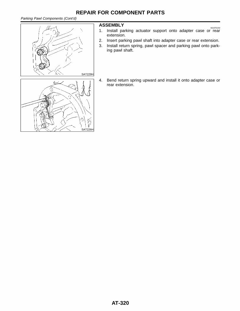
SAT229H
ASSEMBLYNGAT0154
1. Install parking actuator support onto adapter case or rearextension.
2. Insert parking pawl shaft into adapter case or rear extension.3. Install return spring, pawl spacer and parking pawl onto park-
ing pawl shaft.
SAT226H
4. Bend return spring upward and install it onto adapter case orrear extension.
REPAIR FOR COMPONENT PARTSParking Pawl Components (Cont’d)
AT-320
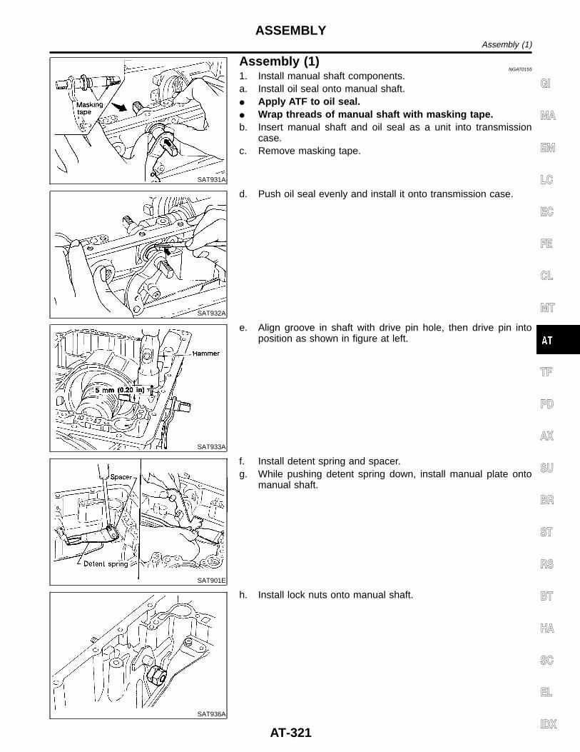
SAT931A
Assembly (1)NGAT0155
1. Install manual shaft components.a. Install oil seal onto manual shaft.I Apply ATF to oil seal.I Wrap threads of manual shaft with masking tape.b. Insert manual shaft and oil seal as a unit into transmission
case.c. Remove masking tape.
SAT932A
d. Push oil seal evenly and install it onto transmission case.
SAT933A
e. Align groove in shaft with drive pin hole, then drive pin intoposition as shown in figure at left.
SAT901E
f. Install detent spring and spacer.g. While pushing detent spring down, install manual plate onto
manual shaft.
SAT936A
h. Install lock nuts onto manual shaft.
GI
MA
EM
LC
EC
FE
CL
MT
TF
PD
AX
SU
BR
ST
RS
BT
HA
SC
EL
IDX
ASSEMBLYAssembly (1)
AT-321
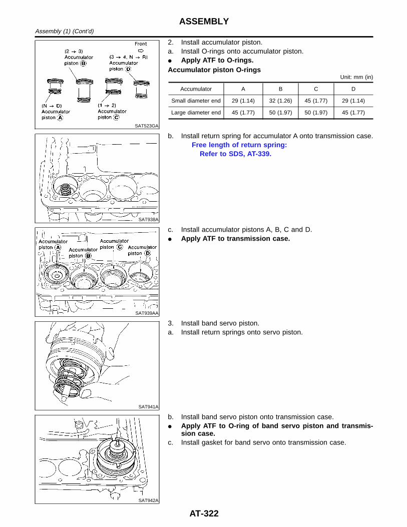
SAT523GA
2. Install accumulator piston.a. Install O-rings onto accumulator piston.I Apply ATF to O-rings.Accumulator piston O-rings
Unit: mm (in)
Accumulator A B C D
Small diameter end 29 (1.14) 32 (1.26) 45 (1.77) 29 (1.14)
Large diameter end 45 (1.77) 50 (1.97) 50 (1.97) 45 (1.77)
SAT938A
b. Install return spring for accumulator A onto transmission case.Free length of return spring:
Refer to SDS, AT-339.
SAT939AA
c. Install accumulator pistons A, B, C and D.I Apply ATF to transmission case.
SAT941A
3. Install band servo piston.a. Install return springs onto servo piston.
SAT942A
b. Install band servo piston onto transmission case.I Apply ATF to O-ring of band servo piston and transmis-
sion case.c. Install gasket for band servo onto transmission case.
ASSEMBLYAssembly (1) (Cont’d)
AT-322
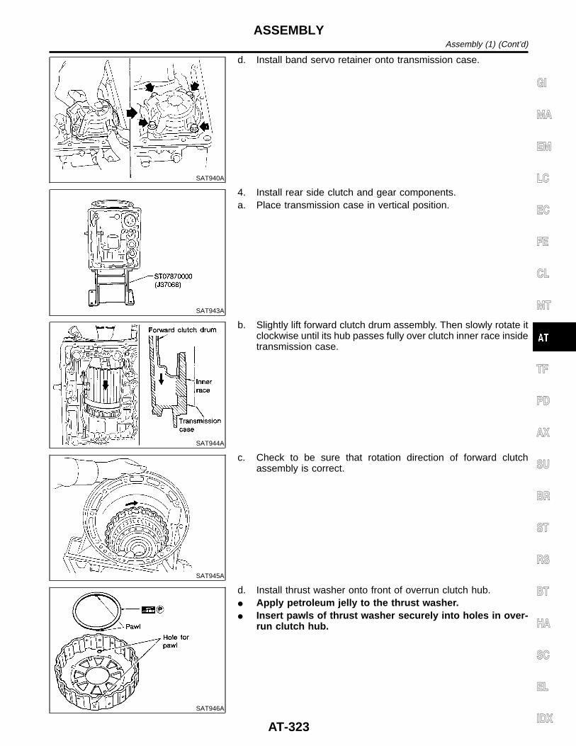
SAT940A
d. Install band servo retainer onto transmission case.
SAT943A
4. Install rear side clutch and gear components.a. Place transmission case in vertical position.
SAT944A
b. Slightly lift forward clutch drum assembly. Then slowly rotate itclockwise until its hub passes fully over clutch inner race insidetransmission case.
SAT945A
c. Check to be sure that rotation direction of forward clutchassembly is correct.
SAT946A
d. Install thrust washer onto front of overrun clutch hub.I Apply petroleum jelly to the thrust washer.I Insert pawls of thrust washer securely into holes in over-
run clutch hub.
GI
MA
EM
LC
EC
FE
CL
MT
TF
PD
AX
SU
BR
ST
RS
BT
HA
SC
EL
IDX
ASSEMBLYAssembly (1) (Cont’d)
AT-323
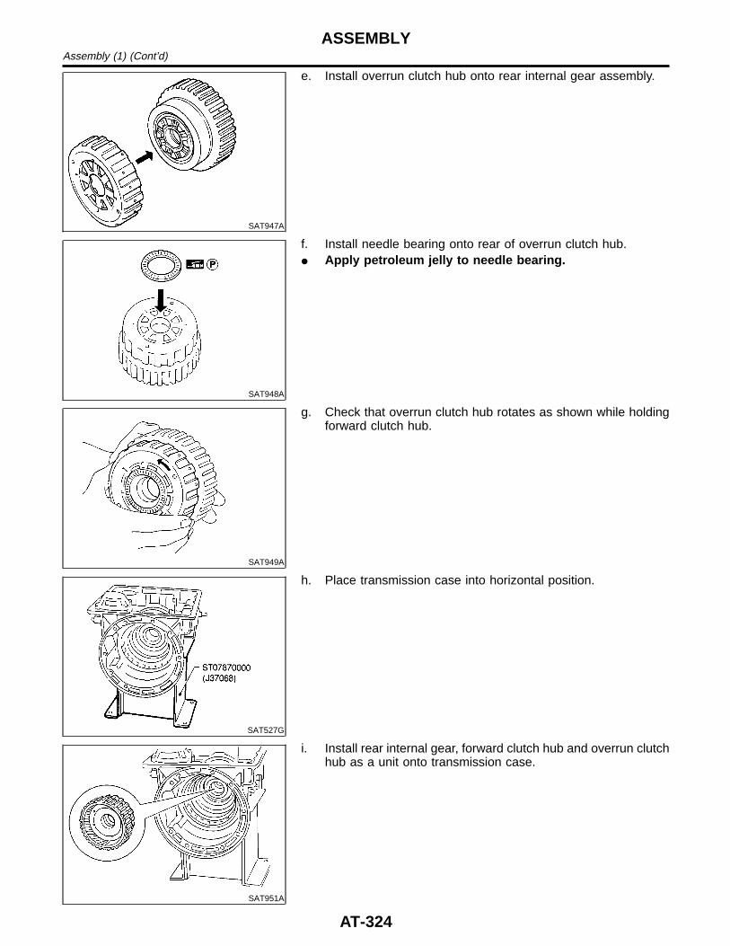
SAT947A
e. Install overrun clutch hub onto rear internal gear assembly.
SAT948A
f. Install needle bearing onto rear of overrun clutch hub.I Apply petroleum jelly to needle bearing.
SAT949A
g. Check that overrun clutch hub rotates as shown while holdingforward clutch hub.
SAT527G
h. Place transmission case into horizontal position.
SAT951A
i. Install rear internal gear, forward clutch hub and overrun clutchhub as a unit onto transmission case.
ASSEMBLYAssembly (1) (Cont’d)
AT-324
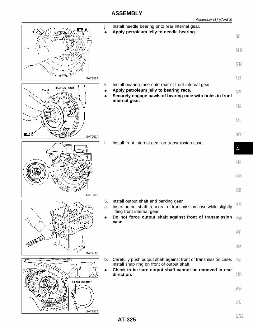
SAT952A
j. Install needle bearing onto rear internal gear.I Apply petroleum jelly to needle bearing.
SAT953A
k. Install bearing race onto rear of front internal gear.I Apply petroleum jelly to bearing race.I Securely engage pawls of bearing race with holes in front
internal gear.
SAT954A
l. Install front internal gear on transmission case.
SAT216B
5. Install output shaft and parking gear.a. Insert output shaft from rear of transmission case while slightly
lifting front internal gear.I Do not force output shaft against front of transmission
case.
SAT957A
b. Carefully push output shaft against front of transmission case.Install snap ring on front of output shaft.
I Check to be sure output shaft cannot be removed in reardirection.
GI
MA
EM
LC
EC
FE
CL
MT
TF
PD
AX
SU
BR
ST
RS
BT
HA
SC
EL
IDX
ASSEMBLYAssembly (1) (Cont’d)
AT-325
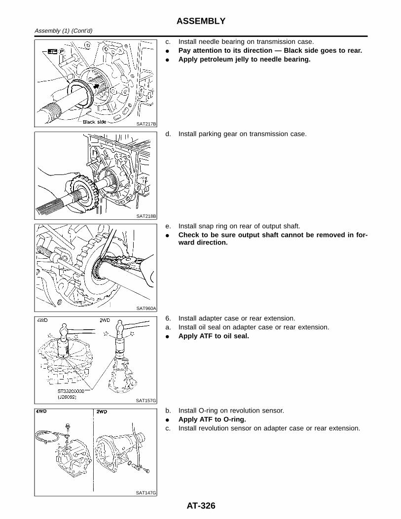
SAT217B
c. Install needle bearing on transmission case.I Pay attention to its direction — Black side goes to rear.I Apply petroleum jelly to needle bearing.
SAT218B
d. Install parking gear on transmission case.
SAT960A
e. Install snap ring on rear of output shaft.I Check to be sure output shaft cannot be removed in for-
ward direction.
SAT157G
6. Install adapter case or rear extension.a. Install oil seal on adapter case or rear extension.I Apply ATF to oil seal.
SAT147G
b. Install O-ring on revolution sensor.I Apply ATF to O-ring.c. Install revolution sensor on adapter case or rear extension.
ASSEMBLYAssembly (1) (Cont’d)
AT-326
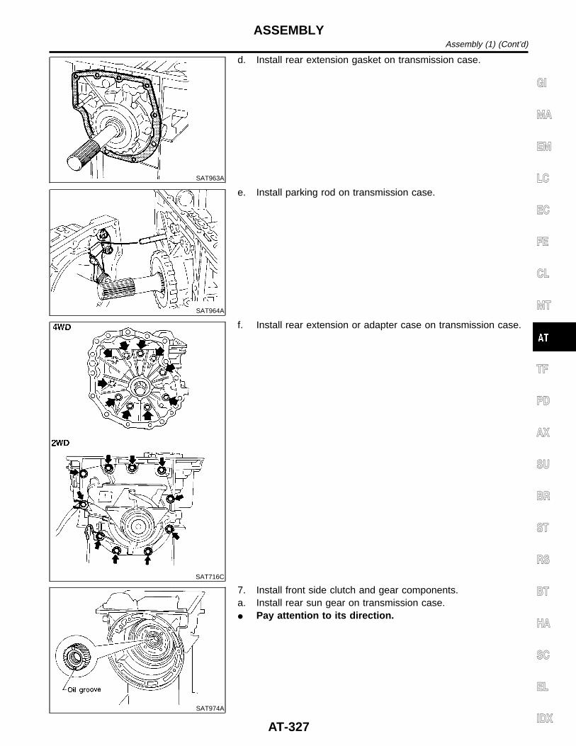
SAT963A
d. Install rear extension gasket on transmission case.
SAT964A
e. Install parking rod on transmission case.
SAT716C
f. Install rear extension or adapter case on transmission case.
SAT974A
7. Install front side clutch and gear components.a. Install rear sun gear on transmission case.I Pay attention to its direction.
GI
MA
EM
LC
EC
FE
CL
MT
TF
PD
AX
SU
BR
ST
RS
BT
HA
SC
EL
IDX
ASSEMBLYAssembly (1) (Cont’d)
AT-327
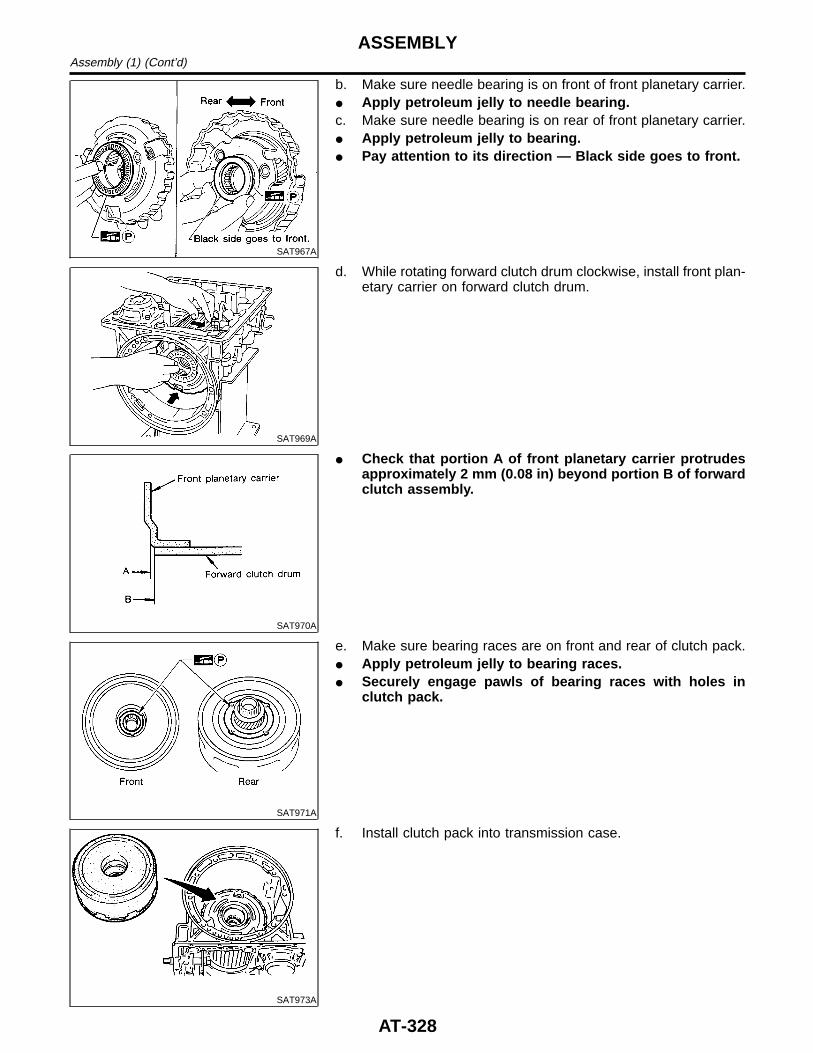
SAT967A
b. Make sure needle bearing is on front of front planetary carrier.I Apply petroleum jelly to needle bearing.c. Make sure needle bearing is on rear of front planetary carrier.I Apply petroleum jelly to bearing.I Pay attention to its direction — Black side goes to front.
SAT969A
d. While rotating forward clutch drum clockwise, install front plan-etary carrier on forward clutch drum.
SAT970A
I Check that portion A of front planetary carrier protrudesapproximately 2 mm (0.08 in) beyond portion B of forwardclutch assembly.
SAT971A
e. Make sure bearing races are on front and rear of clutch pack.I Apply petroleum jelly to bearing races.I Securely engage pawls of bearing races with holes in
clutch pack.
SAT973A
f. Install clutch pack into transmission case.
ASSEMBLYAssembly (1) (Cont’d)
AT-328
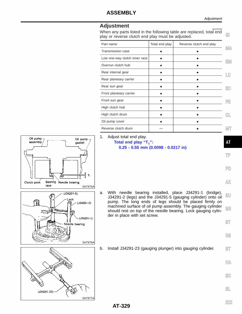
AdjustmentNGAT0156
When any parts listed in the following table are replaced, total endplay or reverse clutch end play must be adjusted.
Part name Total end play Reverse clutch end play
Transmission case I I
Low one-way clutch inner race I I
Overrun clutch hub I I
Rear internal gear I I
Rear planetary carrier I I
Rear sun gear I I
Front planetary carrier I I
Front sun gear I I
High clutch hub I I
High clutch drum I I
Oil pump cover I I
Reverse clutch drum — I
SAT975A
1. Adjust total end play.Total end play “T 1”:
0.25 - 0.55 mm (0.0098 - 0.0217 in)
SAT976A
a. With needle bearing installed, place J34291-1 (bridge),J34291-2 (legs) and the J34291-5 (gauging cylinder) onto oilpump. The long ends of legs should be placed firmly onmachined surface of oil pump assembly. The gauging cylindershould rest on top of the needle bearing. Lock gauging cylin-der in place with set screw.
SAT977A
b. Install J34291-23 (gauging plunger) into gauging cylinder.
GI
MA
EM
LC
EC
FE
CL
MT
TF
PD
AX
SU
BR
ST
RS
BT
HA
SC
EL
IDX
ASSEMBLYAdjustment
AT-329
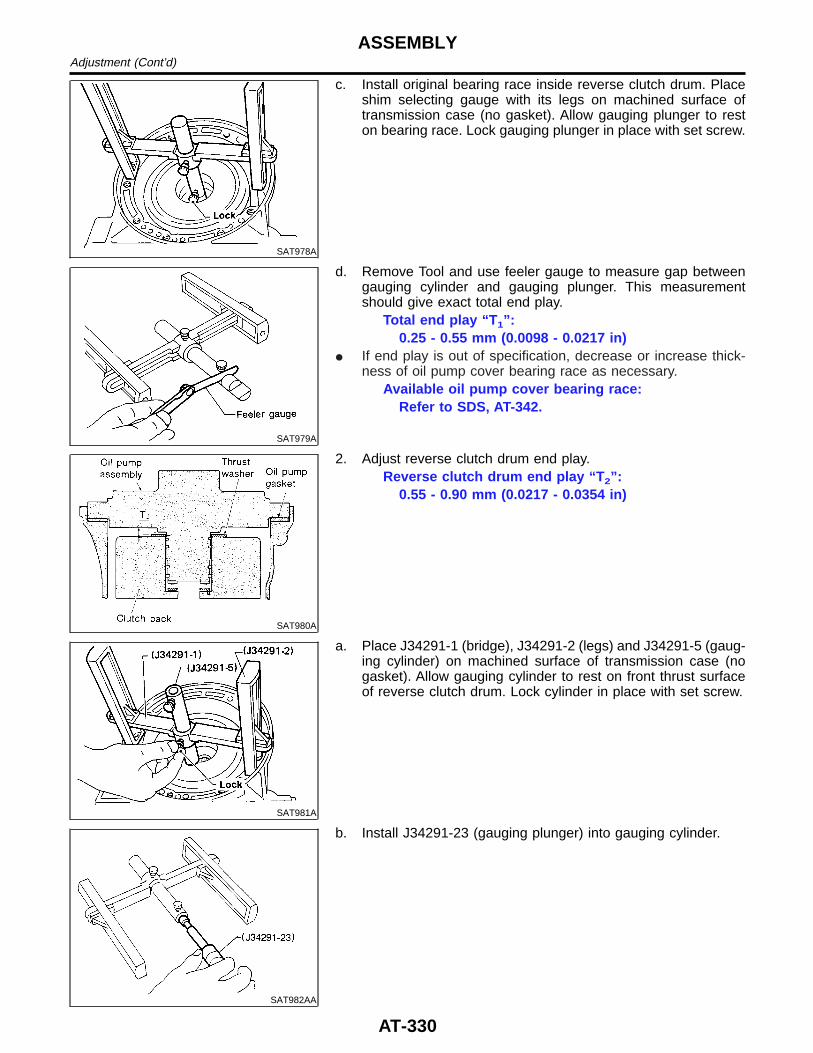
SAT978A
c. Install original bearing race inside reverse clutch drum. Placeshim selecting gauge with its legs on machined surface oftransmission case (no gasket). Allow gauging plunger to reston bearing race. Lock gauging plunger in place with set screw.
SAT979A
d. Remove Tool and use feeler gauge to measure gap betweengauging cylinder and gauging plunger. This measurementshould give exact total end play.
Total end play “T 1”:0.25 - 0.55 mm (0.0098 - 0.0217 in)
I If end play is out of specification, decrease or increase thick-ness of oil pump cover bearing race as necessary.
Available oil pump cover bearing race:Refer to SDS, AT-342.
SAT980A
2. Adjust reverse clutch drum end play.Reverse clutch drum end play “T 2”:
0.55 - 0.90 mm (0.0217 - 0.0354 in)
SAT981A
a. Place J34291-1 (bridge), J34291-2 (legs) and J34291-5 (gaug-ing cylinder) on machined surface of transmission case (nogasket). Allow gauging cylinder to rest on front thrust surfaceof reverse clutch drum. Lock cylinder in place with set screw.
SAT982AA
b. Install J34291-23 (gauging plunger) into gauging cylinder.
ASSEMBLYAdjustment (Cont’d)
AT-330
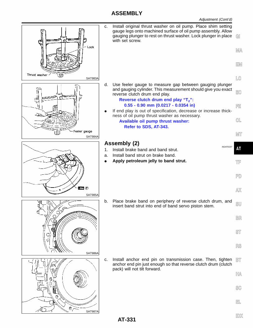
SAT983A
c. Install original thrust washer on oil pump. Place shim settinggauge legs onto machined surface of oil pump assembly. Allowgauging plunger to rest on thrust washer. Lock plunger in placewith set screw.
SAT984A
d. Use feeler gauge to measure gap between gauging plungerand gauging cylinder. This measurement should give you exactreverse clutch drum end play.
Reverse clutch drum end play “T 2”:0.55 - 0.90 mm (0.0217 - 0.0354 in)
I If end play is out of specification, decrease or increase thick-ness of oil pump thrust washer as necessary.
Available oil pump thrust washer:Refer to SDS, AT-343.
SAT985A
Assembly (2)NGAT0157
1. Install brake band and band strut.a. Install band strut on brake band.I Apply petroleum jelly to band strut.
SAT986A
b. Place brake band on periphery of reverse clutch drum, andinsert band strut into end of band servo piston stem.
SAT987A
c. Install anchor end pin on transmission case. Then, tightenanchor end pin just enough so that reverse clutch drum (clutchpack) will not tilt forward.
GI
MA
EM
LC
EC
FE
CL
MT
TF
PD
AX
SU
BR
ST
RS
BT
HA
SC
EL
IDX
ASSEMBLYAdjustment (Cont’d)
AT-331
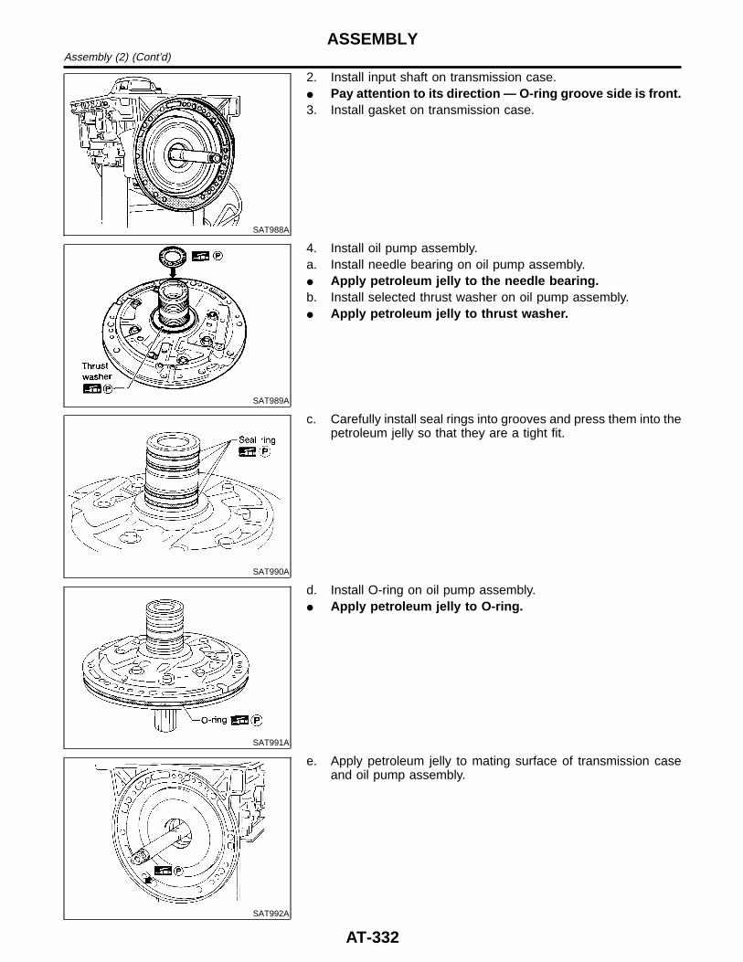
SAT988A
2. Install input shaft on transmission case.I Pay attention to its direction — O-ring groove side is front.3. Install gasket on transmission case.
SAT989A
4. Install oil pump assembly.a. Install needle bearing on oil pump assembly.I Apply petroleum jelly to the needle bearing.b. Install selected thrust washer on oil pump assembly.I Apply petroleum jelly to thrust washer.
SAT990A
c. Carefully install seal rings into grooves and press them into thepetroleum jelly so that they are a tight fit.
SAT991A
d. Install O-ring on oil pump assembly.I Apply petroleum jelly to O-ring.
SAT992A
e. Apply petroleum jelly to mating surface of transmission caseand oil pump assembly.
ASSEMBLYAssembly (2) (Cont’d)
AT-332
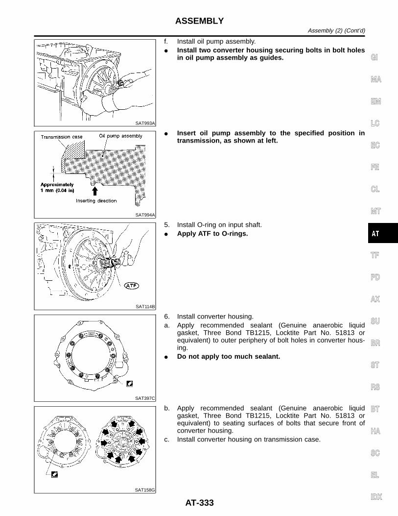
SAT993A
f. Install oil pump assembly.I Install two converter housing securing bolts in bolt holes
in oil pump assembly as guides.
SAT994A
I Insert oil pump assembly to the specified position intransmission, as shown at left.
SAT114B
5. Install O-ring on input shaft.I Apply ATF to O-rings.
SAT397C
6. Install converter housing.a. Apply recommended sealant (Genuine anaerobic liquid
gasket, Three Bond TB1215, Locktite Part No. 51813 orequivalent) to outer periphery of bolt holes in converter hous-ing.
I Do not apply too much sealant.
SAT158G
b. Apply recommended sealant (Genuine anaerobic liquidgasket, Three Bond TB1215, Locktite Part No. 51813 orequivalent) to seating surfaces of bolts that secure front ofconverter housing.
c. Install converter housing on transmission case.
GI
MA
EM
LC
EC
FE
CL
MT
TF
PD
AX
SU
BR
ST
RS
BT
HA
SC
EL
IDX
ASSEMBLYAssembly (2) (Cont’d)
AT-333
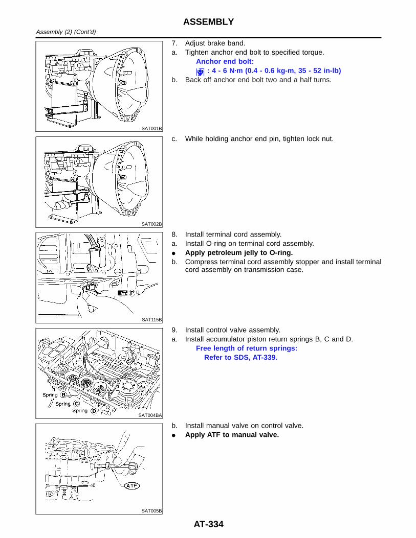
SAT001B
7. Adjust brake band.a. Tighten anchor end bolt to specified torque.
Anchor end bolt:: 4 - 6 N·m (0.4 - 0.6 kg-m, 35 - 52 in-lb)
b. Back off anchor end bolt two and a half turns.
SAT002B
c. While holding anchor end pin, tighten lock nut.
SAT115B
8. Install terminal cord assembly.a. Install O-ring on terminal cord assembly.I Apply petroleum jelly to O-ring.b. Compress terminal cord assembly stopper and install terminal
cord assembly on transmission case.
SAT004BA
9. Install control valve assembly.a. Install accumulator piston return springs B, C and D.
Free length of return springs:Refer to SDS, AT-339.
SAT005B
b. Install manual valve on control valve.I Apply ATF to manual valve.
ASSEMBLYAssembly (2) (Cont’d)
AT-334
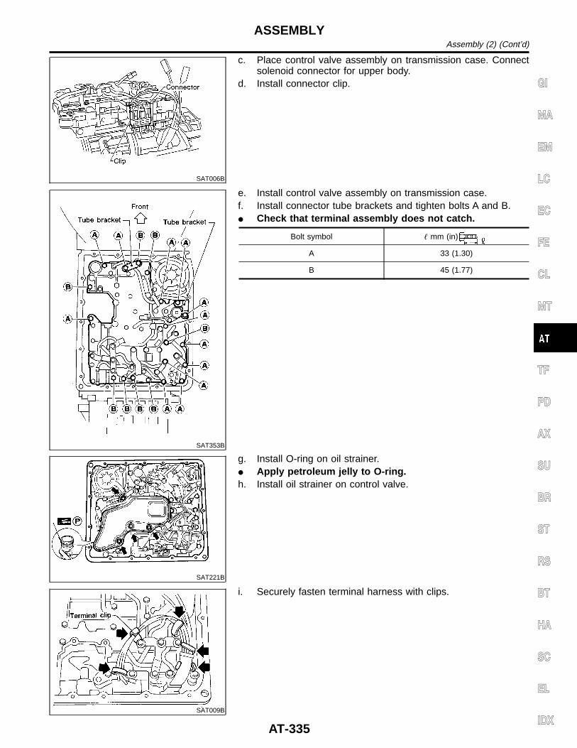
SAT006B
c. Place control valve assembly on transmission case. Connectsolenoid connector for upper body.
d. Install connector clip.
SAT353B
e. Install control valve assembly on transmission case.f. Install connector tube brackets and tighten bolts A and B.I Check that terminal assembly does not catch.
Bolt symbol mm (in)
A 33 (1.30)
B 45 (1.77)
SAT221B
g. Install O-ring on oil strainer.I Apply petroleum jelly to O-ring.h. Install oil strainer on control valve.
SAT009B
i. Securely fasten terminal harness with clips.
GI
MA
EM
LC
EC
FE
CL
MT
TF
PD
AX
SU
BR
ST
RS
BT
HA
SC
EL
IDX
ASSEMBLYAssembly (2) (Cont’d)
AT-335
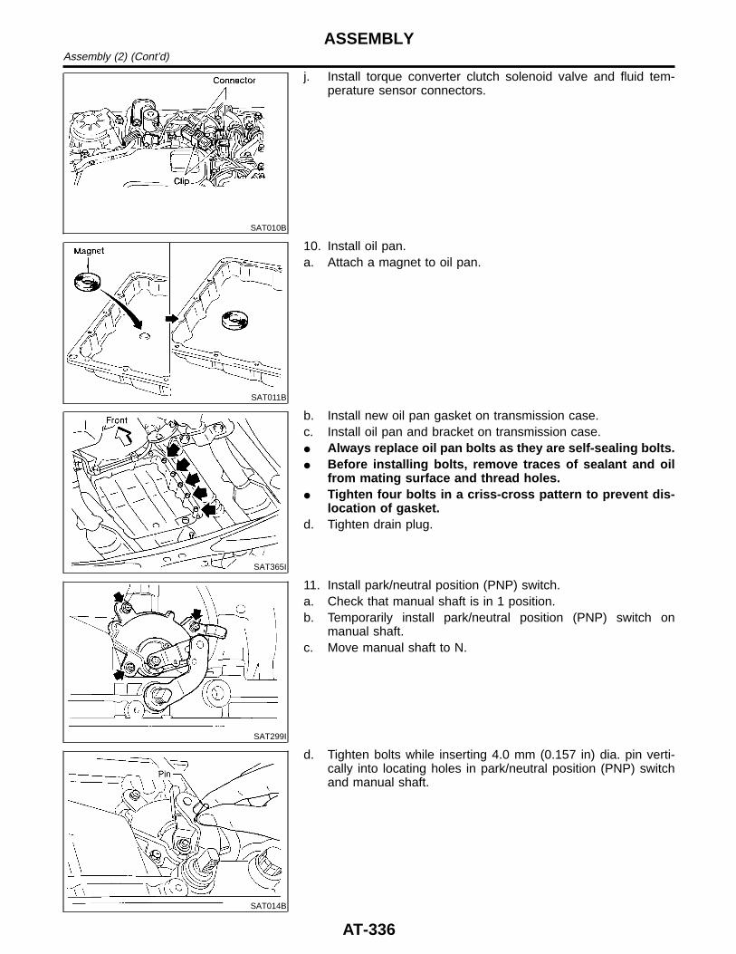
SAT010B
j. Install torque converter clutch solenoid valve and fluid tem-perature sensor connectors.
SAT011B
10. Install oil pan.a. Attach a magnet to oil pan.
SAT365I
b. Install new oil pan gasket on transmission case.c. Install oil pan and bracket on transmission case.I Always replace oil pan bolts as they are self-sealing bolts.I Before installing bolts, remove traces of sealant and oil
from mating surface and thread holes.I Tighten four bolts in a criss-cross pattern to prevent dis-
location of gasket.d. Tighten drain plug.
SAT299I
11. Install park/neutral position (PNP) switch.a. Check that manual shaft is in 1 position.b. Temporarily install park/neutral position (PNP) switch on
manual shaft.c. Move manual shaft to N.
SAT014B
d. Tighten bolts while inserting 4.0 mm (0.157 in) dia. pin verti-cally into locating holes in park/neutral position (PNP) switchand manual shaft.
ASSEMBLYAssembly (2) (Cont’d)
AT-336
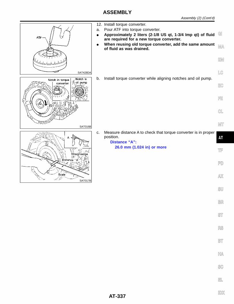
SAT428DA
12. Install torque converter.a. Pour ATF into torque converter.I Approximately 2 liters (2-1/8 US qt, 1-3/4 Imp qt) of fluid
are required for a new torque converter.I When reusing old torque converter, add the same amount
of fluid as was drained.
SAT016B
b. Install torque converter while aligning notches and oil pump.
SAT017B
c. Measure distance A to check that torque converter is in properposition.
Distance “A”:26.0 mm (1.024 in) or more
GI
MA
EM
LC
EC
FE
CL
MT
TF
PD
AX
SU
BR
ST
RS
BT
HA
SC
EL
IDX
ASSEMBLYAssembly (2) (Cont’d)
AT-337
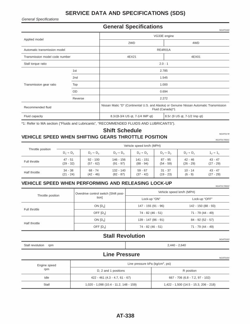
General SpecificationsNGAT0160
Applied modelVG33E engine
2WD 4WD
Automatic transmission model RE4R01A
Transmission model code number 4EX21 4EX01
Stall torque ratio 2.0 : 1
Transmission gear ratio
1st 2.785
2nd 1.545
Top 1.000
OD 0.694
Reverse 2.272
Recommended fluidNissan Matic “D” (Continental U.S. and Alaska) or Genuine Nissan Automatic Transmission
Fluid (Canada)*1
Fluid capacity 8.3(8-3/4 US qt, 7-1/4 IMP qt) 8.5 (9 US qt, 7-1/2 Imp qt)
*1: Refer to MA section (“Fluids and Lubricants”, “RECOMMENDED FLUIDS AND LUBRICANTS”).
Shift ScheduleNGAT0178
VEHICLE SPEED WHEN SHIFTING GEARS THROTTLE POSITIONNGAT0178S01
Throttle positionVehicle speed km/h (MPH)
D1, D2 D2, D3 D3, D4 D4, D3 D3, D2 D2, D1 12, 11
Full throttle47 - 51
(29 - 32)92 - 100(57 - 62)
146 - 156(91 - 97)
141 - 151(88 - 94)
87 - 95(54 - 59)
42 - 46(26 - 29)
43 - 47(27 - 29)
Half throttle34 - 38
(21 - 24)68 - 74
(42 - 46)132 - 140(82 - 87)
59 - 67(37 - 42)
31 - 37(19 - 23)
10 - 14(6 - 9)
43 - 47(27 - 29)
VEHICLE SPEED WHEN PERFORMING AND RELEASING LOCK-UPNGAT0178S02
Throttle positionOverdrive control switch [Shift posi-
tion]
Vehicle speed km/h (MPH)
Lock-up “ON” Lock-up “OFF”
Full throttleON [D4] 147 - 155 (91 - 96) 142 - 150 (88 - 93)
OFF [D3] 74 - 82 (46 - 51) 71 - 79 (44 - 49)
Half throttleON [D4] 139 - 147 (86 - 91) 84 - 92 (52 - 57)
OFF [D3] 74 - 82 (46 - 51) 71 - 79 (44 - 49)
Stall RevolutionNGAT0163
Stall revolution rpm 2,440 - 2,640
Line PressureNGAT0164
Engine speedrpm
Line pressure kPa (kg/cm2, psi)
D, 2 and 1 positions R position
Idle 422 - 461 (4.3 - 4.7, 61 - 67) 667 - 706 (6.8 - 7.2, 97 - 102)
Stall 1,020 - 1,098 (10.4 - 11.2, 148 - 159) 1,422 - 1,500 (14.5 - 15.3, 206 - 218)
SERVICE DATA AND SPECIFICATIONS (SDS)General Specifications
AT-338
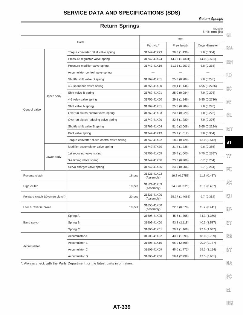
Return SpringsNGAT0165
Unit: mm (in)
PartsItem
Part No.* Free length Outer diameter
Control valve
Upper body
Torque converter relief valve spring 31742-41X23 38.0 (1.496) 9.0 (0.354)
Pressure regulator valve spring 31742-41X24 44.02 (1.7331) 14.0 (0.551)
Pressure modifier valve spring 31742-41X19 31.95 (1.2579) 6.8 (0.268)
Accumulator control valve spring — — —
Shuttle shift valve D spring 31762-41X01 25.0 (0.984) 7.0 (0.276)
4-2 sequence valve spring 31756-41X00 29.1 (1.146) 6.95 (0.2736)
Shift valve B spring 31762-41X01 25.0 (0.984) 7.0 (0.276)
4-2 relay valve spring 31756-41X00 29.1 (1.146) 6.95 (0.2736)
Shift valve A spring 31762-41X01 25.0 (0.984) 7.0 (0.276)
Overrun clutch control valve spring 31762-41X03 23.6 (0.929) 7.0 (0.276)
Overrun clutch reducing valve spring 31742-41X20 32.5 (1.280) 7.0 (0.276)
Shuttle shift valve S spring 31762-41X04 51.0 (2.008) 5.65 (0.2224)
Pilot valve spring 31742-41X13 25.7 (1.012) 9.0 (0.354)
Torque converter clutch control valve spring 31742-41X22 18.5 (0.728) 13.0 (0.512)
Lower body
Modifier accumulator valve spring 31742-27X70 31.4 (1.236) 9.8 (0.386)
1st reducing valve spring 31756-41X05 25.4 (1.000) 6.75 (0.2657)
3-2 timing valve spring 31742-41X06 23.0 (0.906) 6.7 (0.264)
Servo charger valve spring 31742-41X06 23.0 (0.906) 6.7 (0.264)
Reverse clutch 16 pcs31521-41X02(Assembly)
19.7 (0.7756) 11.6 (0.457)
High clutch 10 pcs31521-41X03(Assembly)
24.2 (0.9528) 11.6 (0.457)
Forward clutch (Overrun clutch) 20 pcs31521-41X00(Assembly)
35.77 (1.4083) 9.7 (0.382)
Low & reverse brake 18 pcs31655-41X00(Assembly)
22.3 (0.878) 11.2 (0.441)
Band servo
Spring A 31605-41X05 45.6 (1.795) 34.3 (1.350)
Spring B 31605-41X00 53.8 (2.118) 40.3 (1.587)
Spring C 31605-41X01 29.7 (1.169) 27.6 (1.087)
Accumulator
Accumulator A 31605-41X02 43.0 (1.693) 18.0 (0.709)
Accumulator B 31605-41X10 66.0 (2.598) 20.0 (0.787)
Accumulator C 31605-41X09 45.0 (1.772) 29.3 (1.154)
Accumulator D 31605-41X06 58.4 (2.299) 17.3 (0.681)
*: Always check with the Parts Department for the latest parts information.
GI
MA
EM
LC
EC
FE
CL
MT
TF
PD
AX
SU
BR
ST
RS
BT
HA
SC
EL
IDX
SERVICE DATA AND SPECIFICATIONS (SDS)Return Springs
AT-339
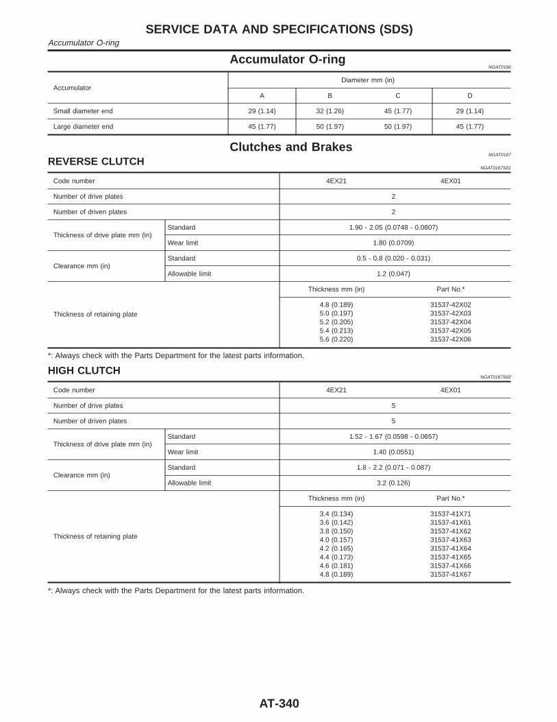
Accumulator O-ringNGAT0166
AccumulatorDiameter mm (in)
A B C D
Small diameter end 29 (1.14) 32 (1.26) 45 (1.77) 29 (1.14)
Large diameter end 45 (1.77) 50 (1.97) 50 (1.97) 45 (1.77)
Clutches and BrakesNGAT0167
REVERSE CLUTCHNGAT0167S01
Code number 4EX21 4EX01
Number of drive plates 2
Number of driven plates 2
Thickness of drive plate mm (in)Standard 1.90 - 2.05 (0.0748 - 0.0807)
Wear limit 1.80 (0.0709)
Clearance mm (in)Standard 0.5 - 0.8 (0.020 - 0.031)
Allowable limit 1.2 (0.047)
Thickness of retaining plate
Thickness mm (in) Part No.*
4.8 (0.189)5.0 (0.197)5.2 (0.205)5.4 (0.213)5.6 (0.220)
31537-42X0231537-42X0331537-42X0431537-42X0531537-42X06
*: Always check with the Parts Department for the latest parts information.
HIGH CLUTCHNGAT0167S02
Code number 4EX21 4EX01
Number of drive plates 5
Number of driven plates 5
Thickness of drive plate mm (in)Standard 1.52 - 1.67 (0.0598 - 0.0657)
Wear limit 1.40 (0.0551)
Clearance mm (in)Standard 1.8 - 2.2 (0.071 - 0.087)
Allowable limit 3.2 (0.126)
Thickness of retaining plate
Thickness mm (in) Part No.*
3.4 (0.134)3.6 (0.142)3.8 (0.150)4.0 (0.157)4.2 (0.165)4.4 (0.173)4.6 (0.181)4.8 (0.189)
31537-41X7131537-41X6131537-41X6231537-41X6331537-41X6431537-41X6531537-41X6631537-41X67
*: Always check with the Parts Department for the latest parts information.
SERVICE DATA AND SPECIFICATIONS (SDS)Accumulator O-ring
AT-340
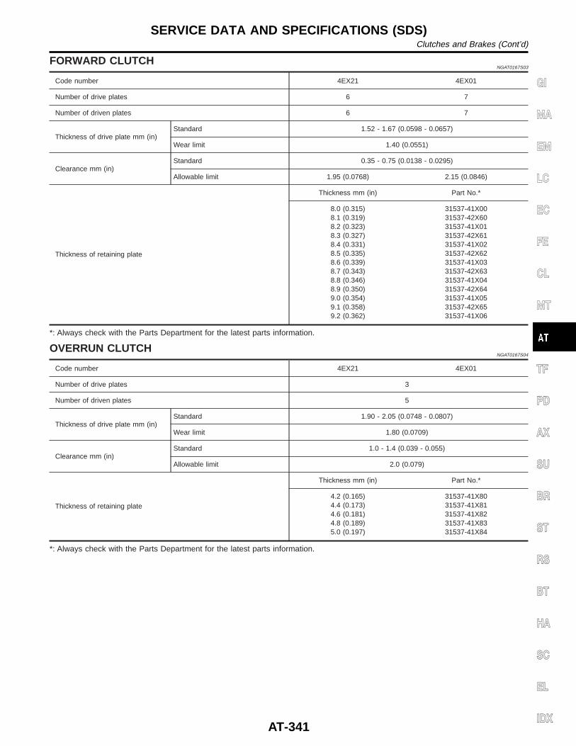
FORWARD CLUTCHNGAT0167S03
Code number 4EX21 4EX01
Number of drive plates 6 7
Number of driven plates 6 7
Thickness of drive plate mm (in)Standard 1.52 - 1.67 (0.0598 - 0.0657)
Wear limit 1.40 (0.0551)
Clearance mm (in)Standard 0.35 - 0.75 (0.0138 - 0.0295)
Allowable limit 1.95 (0.0768) 2.15 (0.0846)
Thickness of retaining plate
Thickness mm (in) Part No.*
8.0 (0.315)8.1 (0.319)8.2 (0.323)8.3 (0.327)8.4 (0.331)8.5 (0.335)8.6 (0.339)8.7 (0.343)8.8 (0.346)8.9 (0.350)9.0 (0.354)9.1 (0.358)9.2 (0.362)
31537-41X0031537-42X6031537-41X0131537-42X6131537-41X0231537-42X6231537-41X0331537-42X6331537-41X0431537-42X6431537-41X0531537-42X6531537-41X06
*: Always check with the Parts Department for the latest parts information.
OVERRUN CLUTCHNGAT0167S04
Code number 4EX21 4EX01
Number of drive plates 3
Number of driven plates 5
Thickness of drive plate mm (in)Standard 1.90 - 2.05 (0.0748 - 0.0807)
Wear limit 1.80 (0.0709)
Clearance mm (in)Standard 1.0 - 1.4 (0.039 - 0.055)
Allowable limit 2.0 (0.079)
Thickness of retaining plate
Thickness mm (in) Part No.*
4.2 (0.165)4.4 (0.173)4.6 (0.181)4.8 (0.189)5.0 (0.197)
31537-41X8031537-41X8131537-41X8231537-41X8331537-41X84
*: Always check with the Parts Department for the latest parts information.
GI
MA
EM
LC
EC
FE
CL
MT
TF
PD
AX
SU
BR
ST
RS
BT
HA
SC
EL
IDX
SERVICE DATA AND SPECIFICATIONS (SDS)Clutches and Brakes (Cont’d)
AT-341
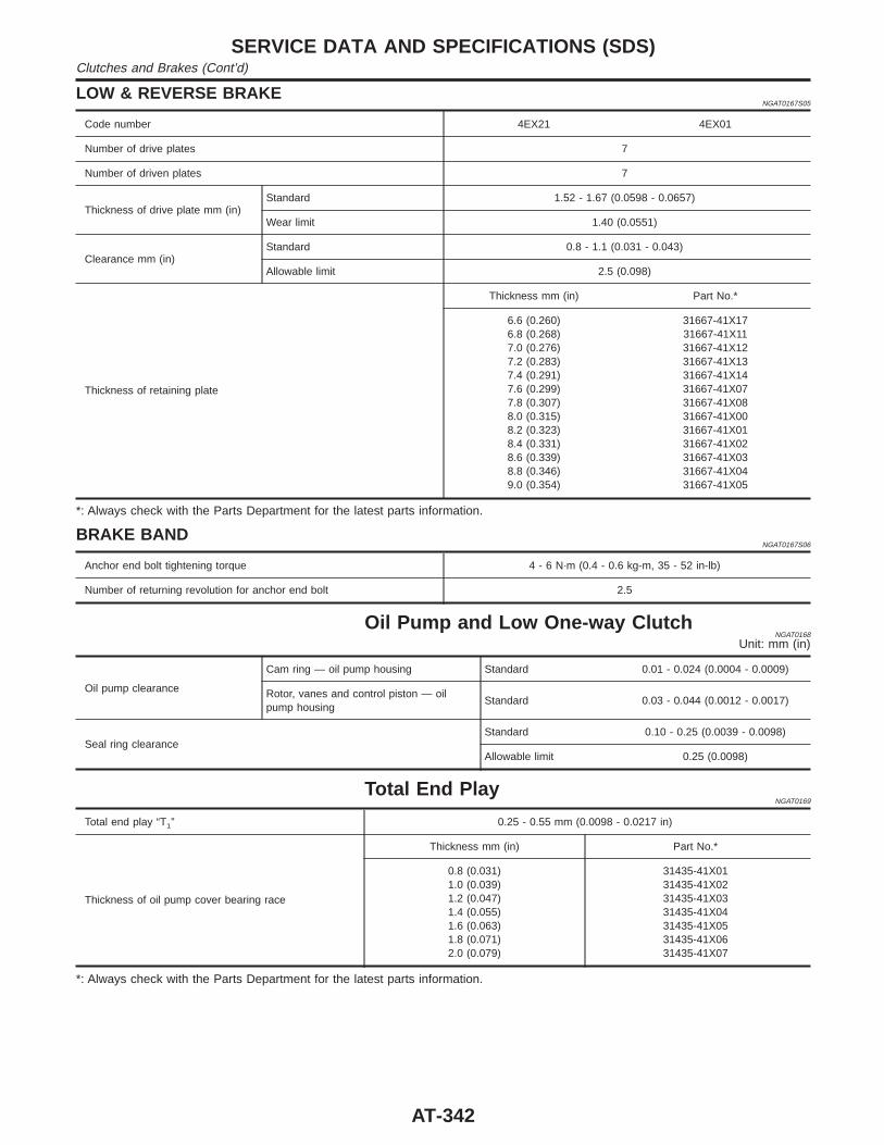
LOW & REVERSE BRAKENGAT0167S05
Code number 4EX21 4EX01
Number of drive plates 7
Number of driven plates 7
Thickness of drive plate mm (in)Standard 1.52 - 1.67 (0.0598 - 0.0657)
Wear limit 1.40 (0.0551)
Clearance mm (in)Standard 0.8 - 1.1 (0.031 - 0.043)
Allowable limit 2.5 (0.098)
Thickness of retaining plate
Thickness mm (in) Part No.*
6.6 (0.260)6.8 (0.268)7.0 (0.276)7.2 (0.283)7.4 (0.291)7.6 (0.299)7.8 (0.307)8.0 (0.315)8.2 (0.323)8.4 (0.331)8.6 (0.339)8.8 (0.346)9.0 (0.354)
31667-41X1731667-41X1131667-41X1231667-41X1331667-41X1431667-41X0731667-41X0831667-41X0031667-41X0131667-41X0231667-41X0331667-41X0431667-41X05
*: Always check with the Parts Department for the latest parts information.
BRAKE BANDNGAT0167S06
Anchor end bolt tightening torque 4 - 6 N·m (0.4 - 0.6 kg-m, 35 - 52 in-lb)
Number of returning revolution for anchor end bolt 2.5
Oil Pump and Low One-way ClutchNGAT0168
Unit: mm (in)
Oil pump clearance
Cam ring — oil pump housing Standard 0.01 - 0.024 (0.0004 - 0.0009)
Rotor, vanes and control piston — oilpump housing
Standard 0.03 - 0.044 (0.0012 - 0.0017)
Seal ring clearanceStandard 0.10 - 0.25 (0.0039 - 0.0098)
Allowable limit 0.25 (0.0098)
Total End PlayNGAT0169
Total end play “T1” 0.25 - 0.55 mm (0.0098 - 0.0217 in)
Thickness of oil pump cover bearing race
Thickness mm (in) Part No.*
0.8 (0.031)1.0 (0.039)1.2 (0.047)1.4 (0.055)1.6 (0.063)1.8 (0.071)2.0 (0.079)
31435-41X0131435-41X0231435-41X0331435-41X0431435-41X0531435-41X0631435-41X07
*: Always check with the Parts Department for the latest parts information.
SERVICE DATA AND SPECIFICATIONS (SDS)Clutches and Brakes (Cont’d)
AT-342
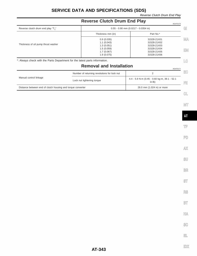
Reverse Clutch Drum End PlayNGAT0170
Reverse clutch drum end play “T2” 0.55 - 0.90 mm (0.0217 - 0.0354 in)
Thickness of oil pump thrust washer
Thickness mm (in) Part No.*
0.9 (0.035)1.1 (0.043)1.3 (0.051)1.5 (0.059)1.7 (0.067)1.9 (0.075)
31528-21X0131528-21X0231528-21X0331528-21X0431528-21X0531528-21X06
*: Always check with the Parts Department for the latest parts information.
Removal and InstallationNGAT0171
Manual control linkage
Number of returning revolutions for lock nut 2
Lock nut tightening torque4.4 - 5.9 N·m (0.45 - 0.60 kg-m, 39.1 - 52.1
in-lb)
Distance between end of clutch housing and torque converter 26.0 mm (1.024 in) or more
GI
MA
EM
LC
EC
FE
CL
MT
TF
PD
AX
SU
BR
ST
RS
BT
HA
SC
EL
IDX
SERVICE DATA AND SPECIFICATIONS (SDS)Reverse Clutch Drum End Play
AT-343

NOTES