2010 doe hydrogen program and vehicle technologies program … · 2010 doe hydrogen program and...
TRANSCRIPT
2010 DOE Hydrogen Program and Vehicle Technologies Program AMR
Fatigue Enhancements by Shock Peening
Curt Lavender, Elizabeth Stephens, and Mark SmithPacific Northwest National Laboratory
Dr. Yong-Ching Chen and Jeffrey CooperCummins Inc.
June 10, 2010
This presentation does not contain any proprietary, confidential, or otherwise restricted information
Project ID# PM002
Overview
Timeline Barriers
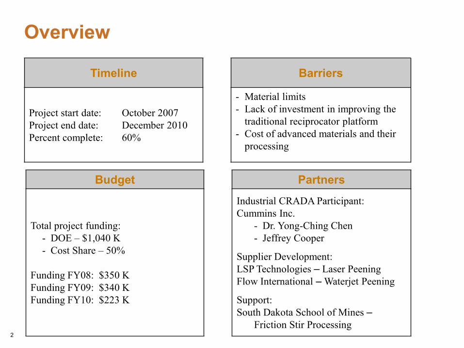
Project start date: October 2007Project end date: December 2010Percent complete: 60%
- Material limits- Lack of investment in improving the
traditional reciprocator platform- Cost of advanced materials and their
processing
Budget Partners
Total project funding: - DOE – $1,040 K- Cost Share – 50%
Funding FY08: $350 KFunding FY09: $340 KFunding FY10: $223 K
Industrial CRADA Participant: Cummins Inc.
- Dr. Yong-Ching Chen- Jeffrey Cooper
Supplier Development:LSP Technologies – Laser PeeningFlow International – Waterjet Peening
Support:South Dakota School of Mines –
Friction Stir Processing2

Objectives of Project
Enable improved engine efficiencies by increasing injection pressures and the overall durability of reciprocating parts
Evaluate the capability for surface modification techniques to improve fatigue performance of steel, aluminum and cast iron engine components
Potentially enabling a lower cost material to meet or exceed the performance of higher cost materials
Surface modification techniques, which are non-traditional for engine manufacturers, include Laser Shock Peening (LSP), Waterjet Peening (WJP), and Friction Stir Processing (FSP)
Materials of interest are steel used in fuel systems and aluminum alloy and cast iron structural components
3
Deliverables
Demonstrate fatigue enhancements achieved by LSP and WJP for steel and aluminum components, including a comparison to traditional shot peening approachesDemonstrate enhancements achieved by FSP for cast iron componentsPrototype a component enhanced by a promising surface modification technique for full scale evaluation
4

Technical ApproachTechnology Development
Fatigue Enhancements in Steel and Aluminum
Demonstrate LSP and WJP produce deep compressive stresses in steel and aluminum test specimensCharacterize stress distributions and compare to control specimensRBF testing of surface modified and control specimensPerform thermal stability tests of surface modified specimensDevelop cost model for process deployment
Friction Stir Process Development for Cast Iron
Demonstrate FSP technique for processing of cast iron Investigate new tool materials and designs for cast iron FSP
Technology DeploymentDemonstrate LSP and WJP surface modification approach on full-scale steel and/or aluminum componentDevelop a cost effective process sequence for LSP/WJP of a relative high volume production
5
Technical Progress
The last year of the project was focused on:
Laser shock peening to enhance the Rolling Contact Fatigue of 52100 steel and Rotating Beam Fatigue life of 52100 steel and A354 cast aluminum
Parameter development for waterjet peening of A354 cast aluminum
Processing development for friction stir processing/joining of cast iron
6
Technical Progress - LSP
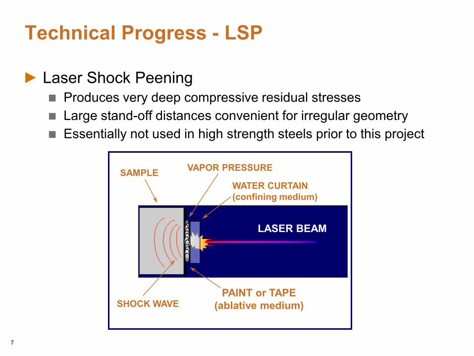
Laser Shock PeeningProduces very deep compressive residual stressesLarge stand-off distances convenient for irregular geometryEssentially not used in high strength steels prior to this project
LASER BEAM
SHOCK WAVE
VAPOR PRESSURE
WATER CURTAIN(confining medium)
SAMPLE
PAINT or TAPE(ablative medium)
7
Technical Progress - LSP
LSP was expected to produce deep compressive stresses therefore unlike most surface peening methods post peening finishing can be usedRotating Beam Fatigue – tested at PNNL
52100 Steel - 4 populations: 1) Control (ground), 2) LSP and ground, 3) as-Shot Peened, and 4) Shot peened and ground
Assumed that as-LSP roughness too highA354 cast aluminum - three populations: 1) Control (ground), 2) as-LSP and 3) LSP and ground
Tested as-LSP to evaluate potential for peening areas that may not be accessible for post-peening finishingCustom alloy prepared at PNNL
Rolling Contact Fatigue – tested at Cummins Inc.52100 steel – tested 2 populations: 1) LSP and ground 2) Control (ground)
8
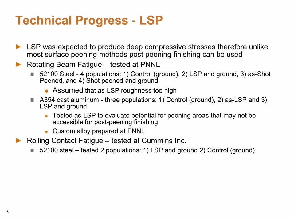
Ground surface finish
Alloy 52100 Steel Specimens Surface Finish Comparison
As-shot peened surface finish
All samples ground after LSP have a ground finish similar to the as-ground
sample on the left9

Longitudinal Residual Stress Distributions of Alloy 52100 Steel Specimens
10
-1725
-1325
-925
-525
-125
275
0 200 400 600 800 1000 1200 1400 1600
-250
-200
-150
-100
-50
0
50
0 10 20 30 40 50 60 70
Residual Stress (M
Pa)Res
idua
l Str
ess (
ksi)
Depth (x 10-3 in.)
Depth (x 10-3 mm)
Control + ground
LSP + ground
As-shot peened
Shot peened + ground
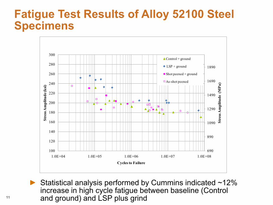
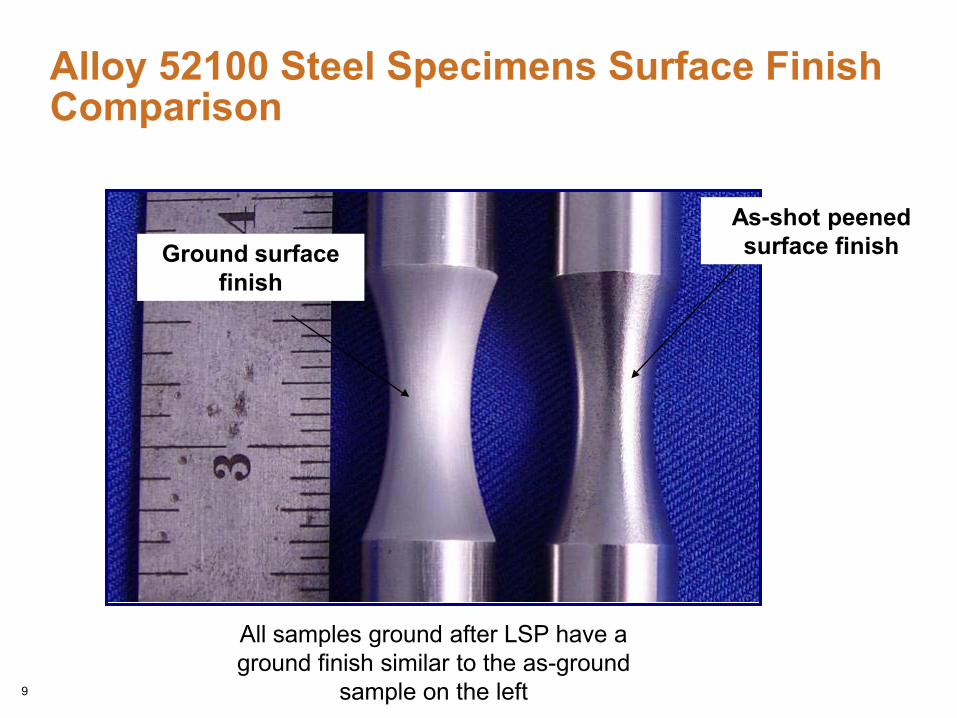
Fatigue Test Results of Alloy 52100 Steel Specimens
11
Statistical analysis performed by Cummins indicated ~12% increase in high cycle fatigue between baseline (Control and ground) and LSP plus grind
690
890
1090
1290
1490
1690
1890
100
120
140
160
180
200
220
240
260
280
300
1.0E+04 1.0E+05 1.0E+06 1.0E+07 1.0E+08
Stre
ss A
mpl
itude
(M
Pa)
Stre
ss A
mpl
itude
(ksi)
Cycles to Failure
Control + ground
LSP + ground
Shot peened + ground
As-shot peened
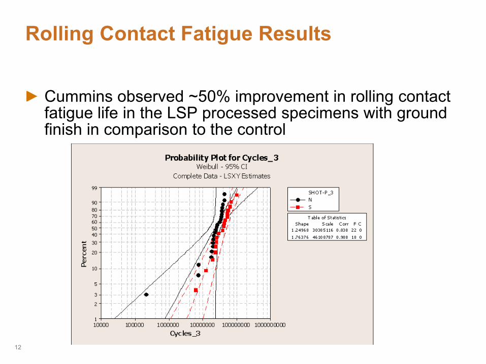
Rolling Contact Fatigue Results
Cummins observed ~50% improvement in rolling contact fatigue life in the LSP processed specimens with ground finish in comparison to the control
12
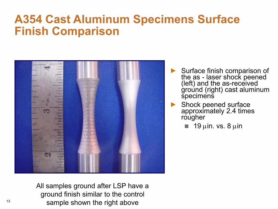
Surface finish comparison of the as - laser shock peened(left) and the as-received ground (right) cast aluminum specimens Shock peened surface approximately 2.4 times rougher
19 µin. vs. 8 µin
A354 Cast Aluminum Specimens Surface Finish Comparison
13
All samples ground after LSP have a ground finish similar to the control
sample shown the right above
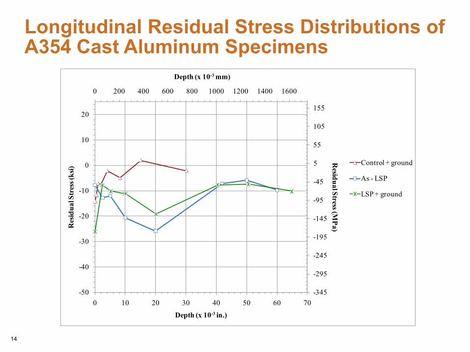
Longitudinal Residual Stress Distributions of A354 Cast Aluminum Specimens
14
-345
-295
-245
-195
-145
-95
-45
5
55
105
155
0 200 400 600 800 1000 1200 1400 1600
-50
-40
-30
-20
-10
0
10
20
0 10 20 30 40 50 60 70
Residual Stress (M
Pa)Res
idua
l Str
ess (
ksi)
Depth (x 10-3 in.)
Depth (x 10-3 mm)
Control + ground
As - LSP
LSP + ground

Preliminary Fatigue Test Results of A354 Cast Aluminum Specimens
15
0
50
100
150
200
0
5
10
15
20
25
30
35
1.0E+05 1.0E+06 1.0E+07 1.0E+08
Stress Am
plitude (MPa)St
ress
Am
plitu
de (k
si)
Cycles to Failure
Control + ground
As - LSP
LSP + ground
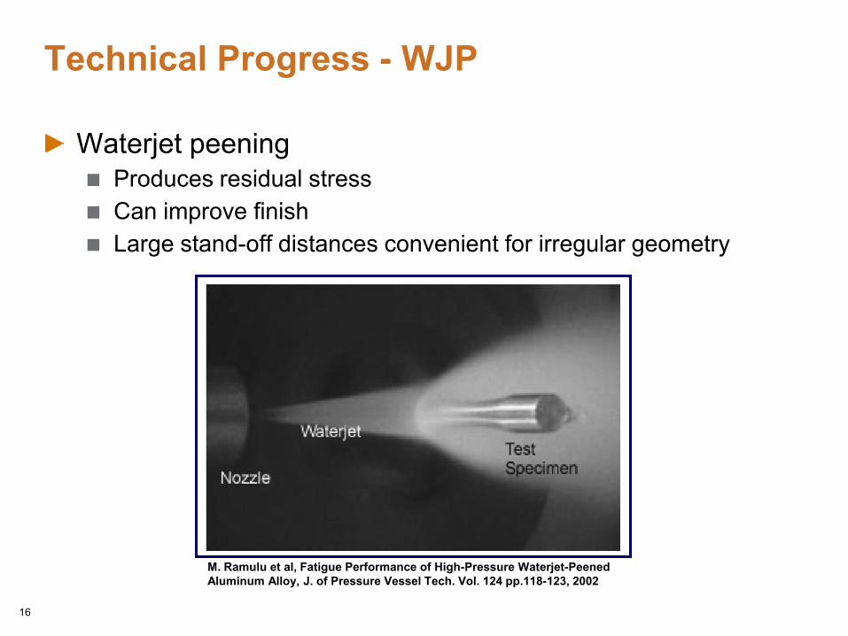
Technical Progress - WJP
Waterjet peeningProduces residual stressCan improve finishLarge stand-off distances convenient for irregular geometry
M. Ramulu et al, Fatigue Performance of High-Pressure Waterjet-Peened Aluminum Alloy, J. of Pressure Vessel Tech. Vol. 124 pp.118-123, 2002
16

Waterjet Peening of A354 Cast Aluminum
Approach focuses on the use of waterjet technology for peening the A354 cast alloy to enhance its fatgiue life
Pre-Screening of waterjet methods to determine the best method to produce a set of samples for evaluation – methods A, B, C
A parametric study to determine the most optimum processing parameters from the most promising methodology will be evaluated by RBF
PressureStand-off distance (the distance between workpiece and nozzle) Speed/feed rate per unit area
17
18
Technical Progress
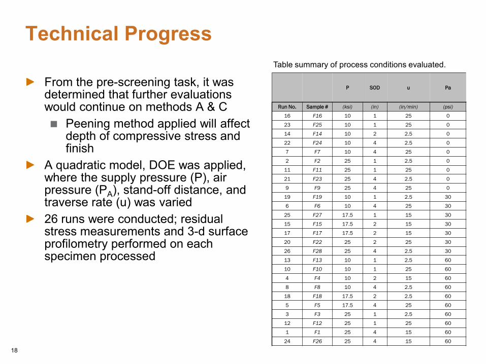
From the pre-screening task, it was determined that further evaluations would continue on methods A & C
Peening method applied will affect depth of compressive stress and finish
A quadratic model, DOE was applied, where the supply pressure (P), air pressure (PA), stand-off distance, and traverse rate (u) was varied26 runs were conducted; residual stress measurements and 3-d surface profilometry performed on each specimen processed
Table summary of process conditions evaluated.
P SOD u Pa
Run No. Sample # (ksi) (in) (in/min) (psi)
16 F16 10 1 25 0
23 F25 10 1 25 0
14 F14 10 2 2.5 0
22 F24 10 4 2.5 0
7 F7 10 4 25 0
2 F2 25 1 2.5 0
11 F11 25 1 25 0
21 F23 25 4 2.5 0
9 F9 25 4 25 0
19 F19 10 1 2.5 30
6 F6 10 4 25 30
25 F27 17.5 1 15 30
15 F15 17.5 2 15 30
17 F17 17.5 2 15 30
20 F22 25 2 25 30
26 F28 25 4 2.5 30
13 F13 10 1 2.5 60
10 F10 10 1 25 60
4 F4 10 2 15 60
8 F8 10 4 2.5 60
18 F18 17.5 2 2.5 60
5 F5 17.5 4 25 60
3 F3 25 1 2.5 60
12 F12 25 1 25 60
1 F1 25 4 15 60
24 F26 25 4 15 60
-345
-295
-245
-195
-145
-95
-45
5
55
105
155
0 100 200 300 400 500 600
-50
-40
-30
-20
-10
0
10
20
0 5 10 15 20 25
Residual Stress (M
Pa)Res
idua
l Str
ess (
ksi)
Depth (x 10-3 in.)
Depth (x 10-3 mm)
Method A specimen
Method C specimen
19
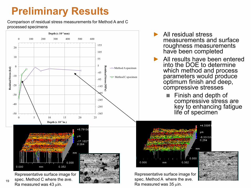
Preliminary Results
All residual stress measurements and surface roughness measurements have been completedAll results have been entered into the DOE to determine which method and process parameters would produce optimum finish and deep, compressive stresses
Finish and depth of compressive stress are key to enhancing fatigue life of specimen
Representative surface image for spec. Method A where the ave. Ra measured was 35 µin.
Representative surface image for spec. Method C where the ave. Ra measured was 43 µin.
Comparison of residual stress measurements for Method A and C processed specimens
DOE Results
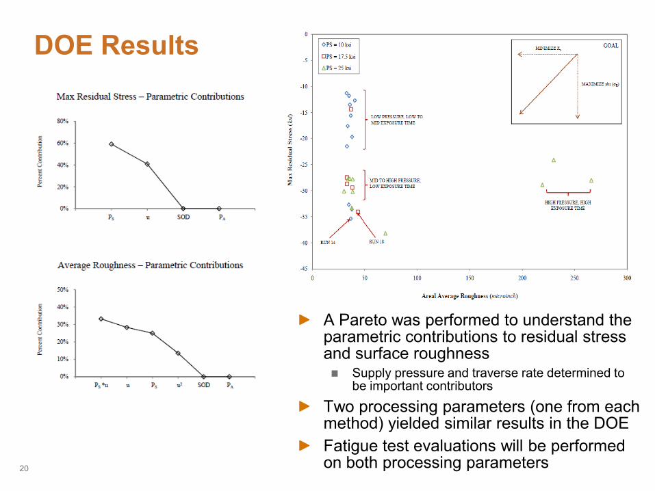
A Pareto was performed to understand the parametric contributions to residual stress and surface roughness
Supply pressure and traverse rate determined to be important contributors
Two processing parameters (one from each method) yielded similar results in the DOEFatigue test evaluations will be performed on both processing parameters20
Technical Progress - FSP of Cast Iron
Cummins’ cast iron surface treatment project with South Dakota School of Mines and Technology under IUCRC grant (Leverages DOE and Cummins Inc. resources)
Developed new coil design to improve plasticizationInvestigating cold spray Fe on cast iron surfaces and evaluating effect of surface modifications Investigating flame coating cast iron plates with a mild steel to allow better induction preheating
PNNL hybrid cast iron surface treatment and joining development using PNNL FSW machine (high vertical force capability)
Microstructural analysis of friction joined cast iron parts performedDeveloping fundamental understanding of structures formed and optimization of the microstructure
Development of friction stir processing of cast iron is ongoingFocusing on achieving plasticization of the material
21
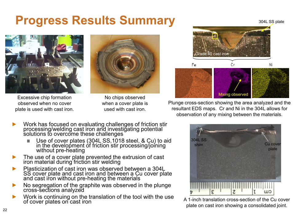
Progress Results Summary
22
Excessive chip formation observed when no cover
plate is used with cast iron.
No chips observed when a cover plate is used with cast iron.
Plunge cross-section showing the area analyzed and the resultant EDS maps. Cr and Ni in the 304L allows for
observation of any mixing between the materials.
304L SS plate
Grade 40 cast iron
Mixing observed
Work has focused on evaluating challenges of friction stir processing/welding cast iron and investigating potential solutions to overcome these challenges
Use of cover plates (304L SS,1018 steel, & Cu) to aid in the development of friction stir processing/joining without pre-heating
The use of a cover plate prevented the extrusion of cast iron material during friction stir weldingPlasticization of cast iron was observed between a 304L SS cover plate and cast iron and between a Cu cover plate and cast iron without pre-heating the materialsNo segregation of the graphite was observed in the plunge cross-sections analyzedWork is continuing on the translation of the tool with the use of cover plates on cast iron
Cu cover plate
304L SS shim
A 1-inch translation cross-section of the Cu cover plate on cast iron showing a consolidated joint.
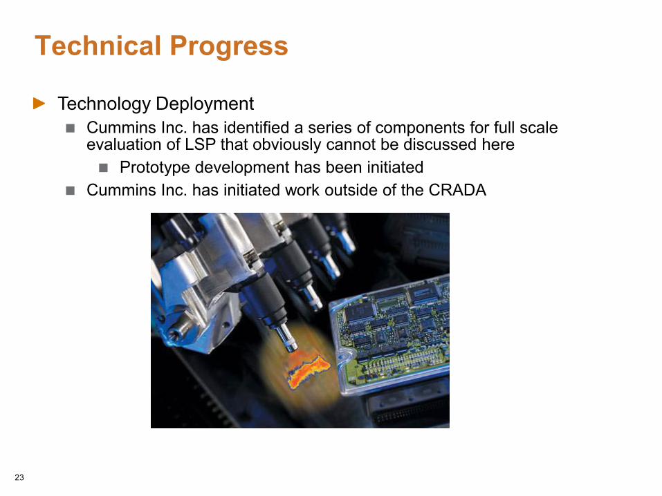
Technical Progress
Technology DeploymentCummins Inc. has identified a series of components for full scale evaluation of LSP that obviously cannot be discussed here
Prototype development has been initiatedCummins Inc. has initiated work outside of the CRADA
23
Future Work
Test real components enhanced by LSPTo be done by Cummins Inc.
Determine thermal stability of LSP induced compressive stresses in 52100 steelComplete RBF testing of waterjet peened cast aluminum alloy A354Continue development of surface treatment techniques of cast iron material via friction stir processing/joiningDevelop a cost model for process deployment
24
SummaryFatigue life of Laser Shock Peened and ground 52100 steel showed significant increase in RBF life over the other populations
Cummins statistical analysis of the fatigue results showed ~12% increase in high cycle fatigueAs expected, the effectiveness of shallow peening methods like shot peening were removed by post peening grinding
Fatigue life of Laser Shock Peened and ground 52100 steel showed significant increase in RCF life over the control population
Cummins statistical analysis of the fatigue results showed ~50% increase in RCF life
Promising results have prompted Cummins Inc. to move to Technology Deployment
LSP fatigue life of cast aluminum alloy A354 was better than the baselineFurther testing is needed to determine whether any statistical significance observed in fatigue life between the LSP & as-LSP populations at higher cyclesBoth LSP and as-LSP populations showed an improvement in fatigue life in comparison to the control
25
Summary, cont.
Waterjet peening can produce surface compressive residual stresses while maintaining surface finish
The DOE identified two promising processing parameters (one from Method A and C) for further fatigue evaluations
Friction Stir Processing/Joining of cast iron developments are ongoing
Plasticization of cast iron observed with the use of cover plates and no pre-heatingNo segregation of graphite was observed in the plunges or translations
26