2018-03-27 matlab®/simulink® - beckhoff · foreword 6 matlab®/simulink®version: 1.1 1.2safety...
TRANSCRIPT

Manual
MATLAB®/Simulink®
TwinCAT 3
1.12018-03-27
Version:Date:

Table of contents
MATLAB®/Simulink® 3Version: 1.1
Table of contents1 Foreword .................................................................................................................................................... 5
1.1 Notes on the documentation........................................................................................................... 51.2 Safety instructions .......................................................................................................................... 6
2 Overview..................................................................................................................................................... 7
3 Block diagram.......................................................................................................................................... 103.1 Using the block diagram ............................................................................................................... 103.2 Integrating the block diagram controls ......................................................................................... 113.3 Debugging .................................................................................................................................... 133.4 Display signal curves .................................................................................................................... 173.5 Module parameterization in the block diagram ............................................................................ 19
4 ADS communication from MATLAB ...................................................................................................... 214.1 Examples ...................................................................................................................................... 21
4.1.1 Accessing an array in the PLC......................................................................................... 214.1.2 Event driven reading ........................................................................................................ 22

Table of contents
MATLAB®/Simulink®4 Version: 1.1

Foreword
MATLAB®/Simulink® 5Version: 1.1
1 Foreword
1.1 Notes on the documentationThis description is only intended for the use of trained specialists in control and automation engineering whoare familiar with the applicable national standards.It is essential that the documentation and the following notes and explanations are followed when installingand commissioning the components. It is the duty of the technical personnel to use the documentation published at the respective time of eachinstallation and commissioning.
The responsible staff must ensure that the application or use of the products described satisfy all therequirements for safety, including all the relevant laws, regulations, guidelines and standards.
Disclaimer
The documentation has been prepared with care. The products described are, however, constantly underdevelopment.We reserve the right to revise and change the documentation at any time and without prior announcement.No claims for the modification of products that have already been supplied may be made on the basis of thedata, diagrams and descriptions in this documentation.
Trademarks
Beckhoff®, TwinCAT®, EtherCAT®, Safety over EtherCAT®, TwinSAFE®, XFC® and XTS® are registeredtrademarks of and licensed by Beckhoff Automation GmbH.Other designations used in this publication may be trademarks whose use by third parties for their ownpurposes could violate the rights of the owners.
Patent Pending
The EtherCAT Technology is covered, including but not limited to the following patent applications andpatents:EP1590927, EP1789857, DE102004044764, DE102007017835with corresponding applications or registrations in various other countries.
The TwinCAT Technology is covered, including but not limited to the following patent applications andpatents:EP0851348, US6167425 with corresponding applications or registrations in various other countries.
EtherCAT® is registered trademark and patented technology, licensed by Beckhoff Automation GmbH,Germany
Copyright
© Beckhoff Automation GmbH & Co. KG, Germany.The reproduction, distribution and utilization of this document as well as the communication of its contents toothers without express authorization are prohibited.Offenders will be held liable for the payment of damages. All rights reserved in the event of the grant of apatent, utility model or design.

Foreword
MATLAB®/Simulink®6 Version: 1.1
1.2 Safety instructions
Safety regulations
Please note the following safety instructions and explanations!Product-specific safety instructions can be found on following pages or in the areas mounting, wiring,commissioning etc.
Exclusion of liability
All the components are supplied in particular hardware and software configurations appropriate for theapplication. Modifications to hardware or software configurations other than those described in thedocumentation are not permitted, and nullify the liability of Beckhoff Automation GmbH & Co. KG.
Personnel qualification
This description is only intended for trained specialists in control, automation and drive engineering who arefamiliar with the applicable national standards.
Description of symbols
In this documentation the following symbols are used with an accompanying safety instruction or note. Thesafety instructions must be read carefully and followed without fail!
DANGER
Serious risk of injury!Failure to follow the safety instructions associated with this symbol directly endangers thelife and health of persons.
WARNING
Risk of injury!Failure to follow the safety instructions associated with this symbol endangers the life andhealth of persons.
CAUTION
Personal injuries!Failure to follow the safety instructions associated with this symbol can lead to injuries topersons.
Attention
Damage to the environment or devicesFailure to follow the instructions associated with this symbol can lead to damage to the en-vironment or equipment.
Note
Tip or pointerThis symbol indicates information that contributes to better understanding.

Overview
MATLAB®/Simulink® 7Version: 1.1
2 OverviewMATLAB®/Simulink®
MATLAB®/Simulink® is a tool for computer-aided modeling, simulation and analysis of physical or biologicalsystems, for example. It has been widely used for many years in research and development. The program isdeveloped and distributed by the company The Mathworks.The models of the simulated systems are usually implemented graphically in the form of block diagrams, asis customary in control technology. The standard Simulink library contains a large number of function blocksthat can be used to represent the behavior of any system. In addition to this standard library, there aretoolboxes for various application areas such as event-based systems, physical systems, control engineering,signal and image processing and much more, which save time and simplify modeling.
Use of MATLAB®/Simulink® in automation technology
One of the strengths of Simulink®, which is particularly interesting for automation technology, is model-basedcontroller optimization. Functions from the higher-level MATLAB® software environment with correspondingtoolboxes can be used for designing control systems based on calculation methods derived from controltheory. Controllers designed in this way can then be simulated and validated in Simulink®, based on a modelof the closed control loop. The software can be used to model and test not only simple control loops and systems, but also wholeproduction plants. This offers several advantages in the development process of a machine. For example, forinitial testing of the control software it is sufficient to use a suitable model of the machine for virtualcommissioning, rather than a physical machine. This also reduces the risk of damage to the machine causedby faulty control software during initial commissioning. For virtual commissioning the TwinCAT 3 functionTE1111 EtherCAT Simulation enables simulation of an EtherCAT segment.
The various Simulink® toolboxes open up a wide range of further application options, including sequentialmachine control with Stateflow® or measurement data evaluation by adding a streaming signal processingsystem with the DSP Systems ToolboxTM.
TE1400 TwinCAT Target for MATLAB®/Simulink®
To use a model from MATLAB®/Simulink® in the actual machine after successful testing, the correspondingalgorithms can be transferred to a PLC program through manual coding, for example. However, automaticconversion of already implemented algorithms to real-time capable program components is simpler andsignificantly less error-prone.
TE1400 TwinCAT Target for MATLAB®/Simulink® can be used to generate real-time capable modules fromMATLAB®/Simulink®, which can be executed in the TwinCAT 3 runtime. These modules can be instantiated,parameterized and debugged multiple times in the TwinCAT 3 development environment.

Overview
MATLAB®/Simulink®8 Version: 1.1
Further information can be found in section TE1400 TwinCAT Target for MATLAB®/Simulink®.
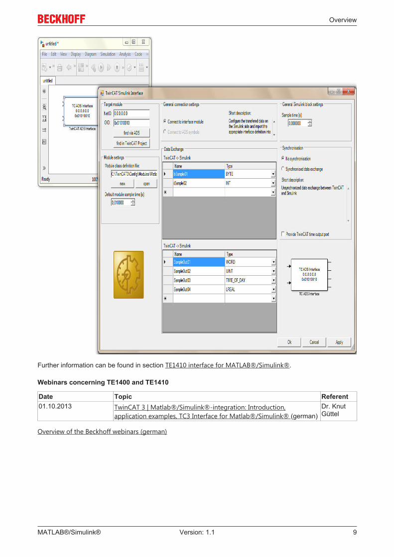
TE1410 interface for MATLAB®/Simulink®
The TE1410 interface for MATLAB®/Simulink® can be used for data exchange between TwinCAT3 andMATLAB®/Simulink®. The data exchange takes place via ADS with the aid of Simulink blocks, which areprovided in a Simulink library.
Overview
MATLAB®/Simulink® 9Version: 1.1
Further information can be found in section TE1410 interface for MATLAB®/Simulink®.
Webinars concerning TE1400 and TE1410
Date Topic Referent01.10.2013 TwinCAT 3 | Matlab®/Simulink®-integration: Introduction,
application examples, TC3 Interface for Matlab®/Simulink® (german)Dr. KnutGüttel
Overview of the Beckhoff webinars (german)

Block diagram
MATLAB®/Simulink®10 Version: 1.1
3 Block diagramWhen generating a TwinCAT module from MATLAB® / Simulink®, the block diagram can optionally also beexported. In this case, the block diagram can be displayed in the TwinCAT development environment underthe Block Diagram tab of the module instance:
This control not only enables navigation through the entire structure of the block diagram, it also enablesviewing and changing of parameter values, display of signal values and their history, and - in debuggingmode - module debugging via breakpoints. The control is designed such that it can also be used in aseparate visualization.
Installation
The block diagram setup is executed with the TwinCAT 3 Setup and does not have to be executedseparately. The version number of the block diagram can be viewed by right-clicking in the control andselecting About TC3 BlockDiagram. Alternatively, you can view the version number in the Control Panelunder Programs and Features (entry Beckhoff TwinCAT 3 BlockDiagram).
3.1 Using the block diagramThe block diagram export can be configured during generation of a TcCOM module from MATLAB® /Simulink®. If this export was enabled, the block diagram can be found in the TwinCAT developmentenvironment under the "Block Diagram" tab of the module instance.
Using shortcuts, drag & drop and a context menu you can navigate through the hierarchy of the TwinCATmodule, view parameter values, display signals values and obtain optional additional debug information.

Block diagram
MATLAB®/Simulink® 11Version: 1.1
Shortcut functions:
Shortcut FunctionSpace Zoom to current size of the block diagram tabBackspace Switch to the next higher hierarchy levelESC Switch to the next higher hierarchy levelCTRL + "+" Zoom inCTRL + "-" Zoom outF5 Attach Debugger
(System- > Real-Time -> C++ Debugger -> Enable C++ Debugger must be activated)
Context menu functions:
3.2 Integrating the block diagram controlsThe option displaying the block diagram in the TwinCAT XAE environment can also be integrated in separatevisualizations.
The following steps are required:
1. Create a new Windows Forms application2. Add the TwinCAT.BlockDiagramm.dll to the toolbox:

Block diagram
MATLAB®/Simulink®12 Version: 1.1
3. Select "Choose Items ..." from the context menu
4. Navigate to TwinCAT.Blockdiagram.dll, which can be found under <TwinCAT installation path>\3.1\Components\TcBlockDiagram

Block diagram
MATLAB®/Simulink® 13Version: 1.1
5. Add a TcBlockdiagram control instance to the Windows Forms object using drag & drop
3.3 DebuggingDifferent ways are available to find errors within a TcCOM module created with MATLAB®/Simulink®, or toanalyze the behavior of the module within the overall architecture of the TwinCAT project.
Debugging in the block diagram
If the block diagram was exported during generation of the TcCOM module, it can be displayed in theTwinCAT development environment and used for debugging within the corresponding module instance, forexample. To do so, the block diagram uses the Microsoft Visual Studio debugger, which can be linked withthe TwinCAT runtime via the TwinCAT debugger port. Attach the debugger as described in the C++ sectionunder Debugging.
Prerequisites for debugging within the block diagram are:
• The C/C++ source code of the TcCOM module must be present on the engineering systems, and theVisual Studio debugger must be able to find it. Ideally, debugging should take place on the system onwhich the code was generated. If the module was created on another system, the associated C/C++source code can usually be made known by integrating the Visual Studio project into the TwinCAT C++section. The file <ModelName>.vcxproj is located in the build directory, see Which files are createdautomatically during code generation and publishing?.
• The module must have been created with the Debug configuration. When publishing takes placedirectly after the code generation, select the Debug setting in the Publish mechanism section underpublish configuration. When publishing the module from the C++ section in TwinCAT, the debuggerin the C++ node of the solution must be enabled; see C/C++ documentation, Debugging.
• During code generation, the options Export block diagram and Export block diagram debuginformation must be enabled in the coder settings under Tc Advanced.
• In the TwinCAT project, the debugger port must be enabled, as described in TwinCAT 3 C++ Enable C++ debugger.
Setting breakpoints in the block diagram1. After attaching the debugger to the TwinCAT runtime, the possible breakpoints are assigned to the
blocks in the block diagram and represented as points. Clicking on the desired breakpoint activates it,so that execution of the module instance is stopped next time the associated block is executed. Thecolor of the point provides information about the current state of the breakpoint:
◦ Grey: Breakpoint inactive
Block diagram
MATLAB®/Simulink®14 Version: 1.1
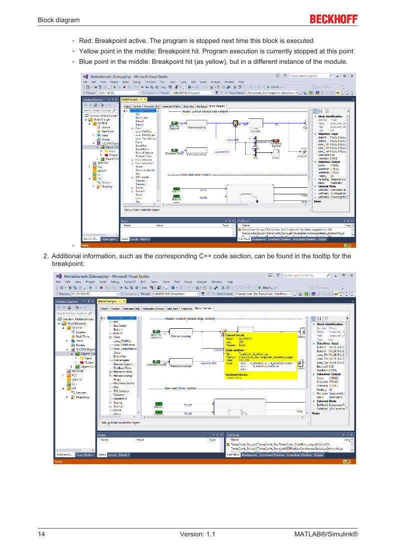
◦ Red: Breakpoint active. The program is stopped next time this block is executed◦ Yellow point in the middle: Breakpoint hit. Program execution is currently stopped at this point◦ Blue point in the middle: Breakpoint hit (as yellow), but in a different instance of the module.
◦2. Additional information, such as the corresponding C++ code section, can be found in the tooltip for the
breakpoint:

Block diagram
MATLAB®/Simulink® 15Version: 1.1
Note
NoteBreakpoints are not always assigned to a single block. In many cases, the functions of sev-eral blocks are consolidated in a code section or even a line in the underlying C++ code.This means that several blocks can share the same breakpoint. Therefore, activation of abreakpoint in the block diagram may also result in changes in the point display in otherblocks.
Evaluating exceptions
If exceptions occur during processing of a TcCOM module, such as division by zero, the point at which theexception occurred can be shown in the block diagram. To this end, the TcCOM module must meet theabove requirements, and the C++ debugger must be enabled in the TwinCAT project (TwinCAT 3 C++Enable C++ debugger). After the debugger has been attached, which may be done before the exception hasoccurred or indeed after, the block that caused the exception is highlighted in the block diagram, providedthe line of code responsible for the exception can be allocated to a block. The name of the block is shown inred, and the block itself is marked in bold.
Manual evaluation of exceptions without source code
Even if the module source code is not available on the engineering system or the C++ debugger was notactivated, you can highlight the error location in the block diagram once an exception has occurred.
Typically, an error message will always be generated when an error occurs, indicating the source file and theline in the source code. In many cases, this information can be used to allocate an exception to a block in theblock diagram. To do this, you can proceed as follows:
ü A prerequisite for highlighting the error location within the block diagram is that debug information wasgenerated (option Export block diagram debug information in the coder settings under Tc Ad-vanced).

Block diagram
MATLAB®/Simulink®16 Version: 1.1
3. From the context menu of the block diagram select the entry Provide exception data:
4. In the dialog that opens, enter the source code file and line number provided in the error message:

Block diagram
MATLAB®/Simulink® 17Version: 1.1
5. The name of the block associated with the line number is displayed in red, and the block itself is markedin bold:
3.4 Display signal curvesFor verification and troubleshooting it is often helpful to display signal curves. The block diagram offers thefollowing options:
Display signal curves in the block diagram
The block diagram offers an option to display signal curves in a window. To this end, drag & drop a signal orblock into a free area of the block diagram.

Block diagram
MATLAB®/Simulink®18 Version: 1.1
Fig. 1: Create a scope in the block diagram
After the drop, a scope window opens in the block diagram.
Fig. 2: Display the scope in the block diagram
The title bar of the scope window offers the following options
Close window
Keep window in the foreground through all block diagram hierarchies
Minimize window to the title bar

Block diagram
MATLAB®/Simulink® 19Version: 1.1
Note
NoticeDisplaying the scope in the block diagram control [} 11] requires a Scope View Profes-sional (TE1300) license. In Visual Studio, this is not necessary.
The scope in the block diagram can be used for a quick overview. For more detailed analyzes, it is advisableto analyze the signals in the TwinCAT Scope.
Display signal curves in TwinCAT Scope
If the item is dropped onto an axis in a Scope project, rather than the block diagram, the signal is addedthere.
Fig. 3: Add a signal in a TwinCAT Scope project
3.5 Module parameterization in the block diagramSection Parameterization of the generated module describes the general parameterization options for aTcCom object. The following section focuses on parameterization in the block diagram.
The Parameter window can be used directly in the block diagram. In addition, the Property table can beused, which can be expanded or collapsed on the right-hand edge of the block diagram. A basic distinction ismade between different parameter values:
"Default", "Startup", "Online" and "Prepared"
The following value types can be found in the drop-down menu of the Property table of the block diagram:
• Default values are the parameter values during code generation. They are invariably stored in themodule description file and enable the manufacturing settings to be restored after parameter changes
• Startup values are stored in the TwinCAT project file and downloaded into the module instance whenTwinCAT starts the module instance.In Simulink modules, it is also possible to specify starting values for the input process image. Thisallows the module to be started with non-zero input values, without the need for linking the inputs withother process images. Internal signals and output signals have no starting values, since they would, inany case, be overwritten in the first cycle.
• Online values are only available if the module was started on the target system. They show thecurrent parameter value in the running module. This value can also be changed during runtime,although in this case the corresponding input field has to be enabled via the context menu, in order toprevent accidental inputs.
• Prepared values can be specified whenever online values are available. They can be used to savevarious values, in order to write them consistently to the module. If prepared values have beenspecified, they are displayed in a table below the block diagram. The buttons to the right of the list canbe used to download prepared values as online values and/or save them as starting value, or deletethem.
Parameterization in the block diagram
Parameterizable blocks are marked with a yellow box in the block diagram.
Block diagram
MATLAB®/Simulink®20 Version: 1.1
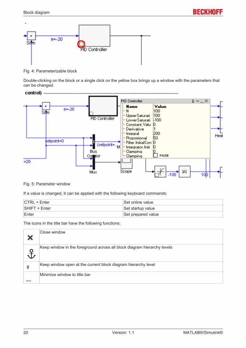
Fig. 4: Parameterizable block
Double-clicking on the block or a single click on the yellow box brings up a window with the parameters thatcan be changed.
Fig. 5: Parameter window
If a value is changed, it can be applied with the following keyboard commands:
CTRL + Enter Set online valueSHIFT + Enter Set startup valueEnter Set prepared value
The icons in the title bar have the following functions:
Close window
Keep window in the foreground across all block diagram hierarchy levels
Keep window open at the current block diagram hierarchy level
Minimize window to title bar

ADS communication from MATLAB
MATLAB®/Simulink® 21Version: 1.1
4 ADS communication from MATLABNo additional software is required for ADS communication from a MATLAB script. After installation ofTwinCAT, the .NET class library "TwinCAT.ADS.dll" is available, for example. This provides .NET classes forrealizing an ADS communication that can be used directly in the MATLAB script.
Description DownloadExample 1: Accessing an array in the PLC [} 21] https://infosys.beckhoff.com/content/1033/
tc3_matlab_overview/Resources/zip/9007200794646283.zip
Example 2: Event driven reading [} 22] https://infosys.beckhoff.com/content/1033/tc3_matlab_overview/Resources/zip/9007200794644619.zip
4.1 ExamplesDescription DownloadExample 1: Accessing an array in the PLC [} 21] https://infosys.beckhoff.com/content/1033/
tc3_matlab_overview/Resources/zip/9007200794646283.zip
Example 2: Event driven reading [} 22] https://infosys.beckhoff.com/content/1033/tc3_matlab_overview/Resources/zip/9007200794644619.zip
4.1.1 Accessing an array in the PLC
Overview
This example is based on Visual C# Example 1. https://infosys.beckhoff.com/content/1033/tc3_matlab_overview/Resources/zip/9007200794646283.zip contains the files described here.
Matlab functionfunction[] = Matlab_ADS_Sample()
Import Ads.dllAdsAssembly = NET.addAssembly('C:\TwinCAT\AdsApi\.NET\v2.0.50727\TwinCAT.Ads.dll');
import TwinCAT.Ads.*
Create instance of class TcAdsClienttcClient = TcAdsClient;
Establish connection to the port 851 on the local computertcClient.Connect(851);
tryhVar = tcClient.CreateVariableHandle('Main.PLCVar');catch errtcClient.Dispose();msgbox(err.message,'Fehler beim Erstellen des Variablenhandles','error');error(err.message);end
AdsStream for recording datadataStream = AdsStream(100 * 2);binRead = AdsBinaryReader(dataStream);

ADS communication from MATLAB
MATLAB®/Simulink®22 Version: 1.1
Read arraytcClient.Read(hVar,dataStream);for i=1:1:100disp(binRead.ReadInt16)endcatch errtcClient.Dispose();msgbox(err.message,'Fehler beim Lesen des Arrays','error');error(err.message);end
Release resourcetcClient.Dispose();
PLC programPROGRAM MAINVARPLCVar : ARRAY [0..99] OF INT;Index: BYTE;END_VARFOR Index := 0 TO 99 DOPLCVar[Index] := 3500 + INDEX;END_FOR
4.1.2 Event driven reading
Overview
This example is based on Visual C# Example 2. https://infosys.beckhoff.com/content/1033/tc3_matlab_overview/Resources/zip/9007200794644619.zip contains the files described here.
The function "OnNotification.m" is automatically called when an ADS notification arrives. The script file"MatlabADSSample_Notification.m" registers the notifications and removes them after a certain time.
MatlabAdsSample_Notification.m
The script file is executed once. First, the ADS notifications are created, and the function "OnNotification" isregistered as a callback. After a certain time, during which ADS notifications were received, the notificationsare deregistered.
Import Ads.dllAdsAssembly = NET.addAssembly('C:\TwinCAT\AdsApi\.NET\v4.0.30319\TwinCAT.Ads.dll');import TwinCAT.Ads.*;
Create instance of class TcAdsClienttcClient = TcAdsClient;
Establish connection to the port 851 on the local computertcClient.Connect(851);
Auxiliary variables for dealing with notifications% ADS streamdataStream = AdsStream(31);% readerbinRead = AdsBinaryReader(dataStream);% notification handleshConnect = zeros(7,1);
% variables to be read from target by notificationboolVarName = 'MAIN.boolVal';intVarName = 'MAIN.intVal';dintVarName = 'MAIN.dintVal';sintVarName = 'MAIN.sintVal';lrealVarName = 'MAIN.lrealVal';realVarName = 'MAIN.realVal';stringVarName = 'MAIN.stringVal';

ADS communication from MATLAB
MATLAB®/Simulink® 23Version: 1.1
Create device notificationstry % Register callback functiontcClient.addlistener('AdsNotification',@OnNotification);
% Register notifications (the variable names are also use as "userData", which can be evaluated bythe callback function)hConnect(1) = tcClient.AddDeviceNotification(boolVarName,dataStream,0,1, AdsTransMode.On-Change,100,0,boolVarName);hConnect(2) = tcClient.AddDeviceNotification(intVarName,dataStream,1,2,AdsTransMode.On-Change,100,0,intVarName);hConnect(3) = tcClient.AddDeviceNotification(dintVarName,dataStream,3,4,AdsTransMode.On-Change,100,0,dintVarName);hConnect(4) = tcClient.AddDeviceNotification(sintVarName,dataStream,7,1,AdsTransMode.On-Change,100,0,sintVarName);hConnect(5) = tcClient.AddDeviceNotification(lrealVarName,dataStream,8,8,AdsTransMode.On-Change,100,0,lrealVarName);hConnect(6) = tcClient.AddDeviceNotification(realVarName,dataStream,16,4,AdsTransMode.On-Change,100,0,realVarName);hConnect(7) = tcClient.AddDeviceNotification(stringVarName,dataStream,20,11,AdsTransMode.On-Change,100,0,stringVarName);
% Listen to ADS notifications for 20 secondspause(20);catch errmsgbox(err.message,'Error reading array via ADS','error');disp(['Error registering ADS notifications: ' err.message]);end
Deregister ADS notificationsfor idx=1:length(hConnect)tcClient.DeleteDeviceNotification(hConnect(idx));end
Close connectiontcClient.Dispose();
Callback function “OnNotification”function OnNotification(sender, e)
Set data stream offsete.DataStream.Position = e.Offset;
The element “UserData” is used to transfer the variable name:valuename = char(e.UserData);
Read variables from the MATLAB workspacehConnect = evalin('base','hConnect');binRead = evalin('base','binRead');
Variable assignment based on the handle, and conversion of the read value to a stringif ( e.NotificationHandle == hConnect(1))strValue = num2str(binRead.ReadBoolean());elseif( e.NotificationHandle == hConnect(2) )strValue = num2str(binRead.ReadInt16());elseif( e.NotificationHandle == hConnect(3) )strValue = num2str(binRead.ReadInt32());elseif( e.NotificationHandle == hConnect(4) )strValue = num2str(binRead.ReadSByte());elseif( e.NotificationHandle == hConnect(5) )strValue = num2str(binRead.ReadDouble());elseif( e.NotificationHandle == hConnect(6) )strValue = num2str(binRead.ReadSingle());elseif( e.NotificationHandle == hConnect(7) )strValue = char(System.String(binRead.ReadChars(11))); end
Output of the received value

ADS communication from MATLAB
MATLAB®/Simulink®24 Version: 1.1
disp(sprintf('Notification received at %04d-%02d-%02d %02d:%02d:%02.3f:\t %s = \t %s',clock(),value-name,strValue));
PLC programPROGRAM MAINVARboolVal : BOOL;intVal : INT := 222;dintVal : DINT;sintVal : SINT;lrealVal : LREAL := 22.2;realVal : REAL;stringVal : STRING(10);END_VARdintVal := dintVal+1;