2021 minghao jiang
TRANSCRIPT

© 2021 MINGHAO JIANG
CONTINUOUS INTEGRATION AND TESTING FOR AUTONOMOUSRACING IN SIMULATION
BY
MINGHAO JIANG
THESIS
Submitted in partial fulfillment of the requirementsfor the degree of Master of Science in Electrical and Computer Engineering
in the Graduate College of theUniversity of Illinois Urbana-Champaign, 2021
Urbana, Illinois
Adviser:
Professor Sayan Mitra
ABSTRACT
Self-driving autonomous vehicles (AVs) have recently gained in popularity
as a research topic. The safety of AVs is exceptionally important as failure
in the design of an AV could lead to catastrophic consequences. AV systems
are highly heterogeneous with many different and complex components, so
it is difficult to perform end-to-end testing. One solution to this dilemma is
to evaluate AVs using simulated racing competition.
In this thesis, we present a simulated autonomous racing competition, Gen-
eralized RAcing Intelligence Competition (GRAIC). To compete in GRAIC,
participants need to submit their controller files which are deployed on a
racing ego-vehicle on different race tracks. To evaluate the submitted con-
troller, we also developed a testing pipeline, Autonomous System Operations
(AutOps). AutOps is an automated, scalable, and fair testing pipeline devel-
oped using software engineering techniques such as continuous integration,
containerization, and serverless computing.
In order to evaluate the submitted controller in non-trivial circumstances,
we populate the race tracks with scenarios, which are pre-defined traffic sit-
uations commonly seen in the real road. We present a dynamic scenario
testing strategy that generates new scenarios based on results of the ego-
vehicle passing through previous scenarios.
ii

To my parents, for their love and support.
iii

ACKNOWLEDGMENTS
First, I would like to sincerely thank my adviser Prof. Sayan Mitra of the
Department of Electrical and Computer Engineering at the University of
Illinois at Urbana-Champaign. From 2017, I have worked as a Research
Assistant in his group where I have learned how to apply my knowledge and
skills to solving real world problems in the area of safety autonomy. Prof.
Mitra not only supported me with both academic and financial assistance,
but he also guided me in tackling difficulties in my life. This thesis would
have been impossible to complete without his help.
Thanks to Dawei Sun, Kristina Miller, and other team members from
GRAIC for their help and insights on working together in this project. It is
a great pleasure to work with all of you. I also appreciate Yangge Li for his
help in the development of the scenario generation algorithm.
I would also like to thank my parents for their unconditional mental and
financial support of my study in the United States from 2015. Their help is
crucial for my life.
Finally, I would like to thank my girlfriend Wanyue Xiao for her company
during the completion of this work.
iv
TABLE OF CONTENTS
CHAPTER 1 INTRODUCTION . . . . . . . . . . . . . . . . . . . . 11.1 Motivation: Safe Autonomy . . . . . . . . . . . . . . . . . . . 11.2 Challenges in AV Testing . . . . . . . . . . . . . . . . . . . . . 21.3 Contributions of the Thesis and an Overview . . . . . . . . . . 41.4 Organization of Thesis . . . . . . . . . . . . . . . . . . . . . . 5
CHAPTER 2 RELATED WORK . . . . . . . . . . . . . . . . . . . . 72.1 Simulated Autonomous Racing . . . . . . . . . . . . . . . . . 72.2 Continuous Integration for Autonomy and Robotics . . . . . . 92.3 Generating Scenarios for Testing . . . . . . . . . . . . . . . . . 102.4 Formal Verification for Simulation Models . . . . . . . . . . . 112.5 Summary . . . . . . . . . . . . . . . . . . . . . . . . . . . . . 13
CHAPTER 3 AUTONOMOUS RACING TESTING PIPELINE . . . 143.1 GRAIC Framework . . . . . . . . . . . . . . . . . . . . . . . . 143.2 Design of a Testing Pipeline . . . . . . . . . . . . . . . . . . . 173.3 Experimental Evaluation . . . . . . . . . . . . . . . . . . . . . 213.4 Summary . . . . . . . . . . . . . . . . . . . . . . . . . . . . . 25
CHAPTER 4 CREATING SCENARIOS FOR TESTING . . . . . . . 264.1 Testing using Scenario Runner . . . . . . . . . . . . . . . . . . 264.2 Integrate Scenario Test to GRAIC . . . . . . . . . . . . . . . . 294.3 Scenario Generation Strategy . . . . . . . . . . . . . . . . . . 304.4 Scenario Testing and Determinism . . . . . . . . . . . . . . . . 354.5 Summary . . . . . . . . . . . . . . . . . . . . . . . . . . . . . 36
CHAPTER 5 CONCLUSION AND FUTURE WORK . . . . . . . . 37
REFERENCES . . . . . . . . . . . . . . . . . . . . . . . . . . . . . . . 39
v
CHAPTER 1
INTRODUCTION
1.1 Motivation: Safe Autonomy
Self-driving autonomous vehicles (AV) have recently gained in popularity
as a research topic. The safety assurance of AVs has become exceptionally
important. Any minor glitches in the design of autonomous driving system
can lead to disastrous outcomes. For example, the crash of an Uber AV in
Tempe, AZ [1], resulted in a majority cessation of Uber’s AV testing, and
finally caused Uber to sell its Advanced Technology Group (Uber ATG) to
Aurora in 2020 [2]. In general, it is widely believed that to ensure the safety of
AV, extensive road tests are required. According to Professor Shashua from
CMU, 30 million miles of road tests will be needed to achieve the same fatality
rate as that of human drivers [3]. Emerging companies such as Waymo or
Zoox have developed and deployed their AVs which have been driven for
millions of miles on real road. According to the report from the DMV, State
of California, Waymo performed AV road tests for a mileage of roughly 1.45
million miles and 0.63 million miles in 2019 [4] and 2020 [5] respectively.
Nevertheless, it is still far from the desired road test distance for safety
assurance. The scalability and exhaustiveness of testing AVs has been an
immense concern among the industry.
To supplement the deficiency of road test in real world, the industry and
institutions have sought to conduct tests in simulation software. In the sim-
ulation, researchers and engineers have more freedom and convenience in de-
signing and formulating their tests without worrying excessively about catas-
trophic consequences. The capability of running automated and concurrent
tests is highly desired to increase the scalability and efficiency. In modern
software engineering, continuous integration and containerization techniques
are often exploited to achieve the goals in software quality and reliability test-
1
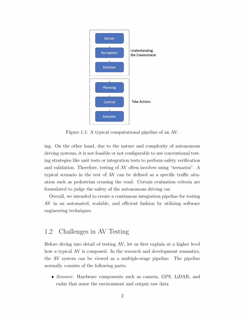
Figure 1.1: A typical computational pipeline of an AV.
ing. On the other hand, due to the nature and complexity of autonomous
driving systems, it is not feasible or not configurable to use conventional test-
ing strategies like unit tests or integration tests to perform safety verification
and validation. Therefore, testing of AV often involves using “scenarios”. A
typical scenario in the test of AV can be defined as a specific traffic situ-
ation such as pedestrian crossing the road. Certain evaluation criteria are
formulated to judge the safety of the autonomous driving car.
Overall, we intended to create a continuous integration pipeline for testing
AV in an automated, scalable, and efficient fashion by utilizing software
engineering techniques.
1.2 Challenges in AV Testing
Before diving into detail of testing AV, let us first explain at a higher level
how a typical AV is composed. In the research and development semantics,
the AV system can be viewed as a multiple-stage pipeline. The pipeline
normally consists of the following parts:
• Sensors : Hardware components such as camera, GPS, LiDAR, and
radar that sense the environment and output raw data
2

• Perception: A software module that abstracts and processes raw data
from sensor into data structure
• Decision: Based on perception input, this module makes decisions,
predictions, and actions
• Planning : Searches for optimal path based on the instructions from
decision module
• Control : Calculates control command for actuator to follow the gener-
ated path from planning module
• Actuators : Hardware module that actually manipulates the vehicle to
move and turn
Figure 1.1 illustrates the AV system. The pipeline can even be further
separated into more fine-grained components. Nevertheless, the high hetero-
geneity of AV is obvious as each component contains multiple variables that
can be either hardware or software. Each component can introduce some
uncertainty to the overall system. Therefore, testing the AV pipeline as an
end-to-end system can be extremely complicated.
Another challenge for the testing of AVs is the lack of standardized bench-
marks. It is hard to find a benchmark for each component, especially for the
decision, planning, and controller modules. Unlike perception benchmarks
like ImageNet [6], creating benchmarks for control and autonomy is much
more challenging because they require a complete executable specification
for a closed-loop system, the dynamics of the ego-vehicle, the static environ-
ment, the behaviors of active and passive agents in the environment, their
interactions, and the perception and control interfaces for the ego-vehicle.
One solution to tackle the two challenges is to use simulated autonomous
racing competition. While the AV pipeline is highly heterogeneous, the input
and output to the system should be similar. The AV system can be deployed
to a virtual vehicle model inside simulation software. Then, the input to
the system is the surrounding environment, while the output is the vehicle
actuation, such as throttle, brake, and steering. During the competition,
evaluation of the AV is performed based on the recorded vehicle behaviors.
Therefore, testing the AV using simulated autonomous racing competition
is one of the approaches to solve the problem of end-to-end testing of the AV.
3
Then, we ask ourselves another question: How to benchmark the performance
of AV controller scalably, automatically, and fairly? To answer this question,
this thesis proposes an autonomous racing framework, a testing pipeline, and
a scenario generation algorithm.
1.3 Contributions of the Thesis and an Overview
Towards addressing the scalability of testing AV in simulated autonomous
racing, this thesis makes three main contributions summarized in the follow-
ing three subsections.
1.3.1 GRAIC Framework
Based on CARLA simulator and ROS, we developed an autonomous racing
framework as shown in Figure 1.2. Generalized RAcing Intelligence Compe-
tition, known as GRAIC [7], provides ground truth perception results so that
participants can focus on designing the decision and control sections of the
autonomous pipeline. Participants develop a controller that manipulates a
simulated vehicle that is generalized to be able to run on multiple tracks with
different environmental configurations in GRAIC. Meanwhile, metrics are
calculated to indicate the effectiveness of the developed controller. GRAIC
serves as a benchmark for testing AV as an end-to-end system.
1.3.2 Testing Pipeline
To overcome the scalability issue of testing AV in GRAIC, we created a three-
stage testing pipeline based on modern software engineering techniques such
as continuous integration, Docker container, and serverless cloud computing.
It serves as the backend testing framework for GRAIC. At a high level, the
three-stage pipeline contains the code source, build server, and result de-
liverer. Our pipeline achieved full automation meaning that the tests can
be automatically triggered by changing the code source and no human in-
terference is needed during the testing phases. The testing pipeline ensures
determinism in the results obtained from every test within a certain level of
error.
4

Figure 1.2: GRAIC running on Ubuntu 20.04 with CARLA and ROSNoetic.
1.3.3 Scenario Testing
In order to test the AV as an end-to-end system in non-trivial environments,
we use scenarios that simulate traffic situations commonly seen on the road.
The scenario defines the obstacle configuration and its behavior, which tries
to prevent AV from proceeding in race. This thesis presents a scenario test-
ing framework that is capable of dynamically generating scenarios based on
results of previous scenarios. Through the use of scenarios, we can possibly
locate more design flaws and implementation bugs in the AV system.
1.4 Organization of Thesis
This thesis is organized as follows:
Chapter 2 will discuss related work in autonomous racing and compare that
work to the GRAIC framework by discussing some advantages and disadvan-
tages. Moreover, we will also walk through some existing work in continuous
integration and scenario generation in the area of testing AV.
Chapter 3 presents the main contribution of the thesis. First, we explain
the details and features of the GRAIC framework. Then, we dive into the
implementation of the testing pipeline in great detail and illustrate how it
works. Finally, we discuss the determinism and performance of the pipeline
5

and how we optimize them.
In Chapter 4, we describe our scenario testing framework based on sce-
nario runner [8] from CARLA and its operation principles. We also propose
a scenario compilation strategy based on results of how the AV behaves and
performs in the previous scenarios.
In Chapter 5, we offer conclusions and propose possible tracks for improve-
ment in future work.
6

CHAPTER 2
RELATED WORK
In this chapter, we present a discussion of the literature related to the main
topics of the thesis. The discussion is organized into three parts: simula-
tion tools available for autonomous racing, works on continuous integration
(CI) and testing for autonomous systems, and methods for generating and
verifying scenarios for autonomous driving.
2.1 Simulated Autonomous Racing
A large number of software tools are available for simulating vehicles for gam-
ing, control engineering, and software testing. Currently, mature simulation
software packages such as CARLA [9], Gazebo [10], LGSVL [11], and GTA
V [12] have been utilized by different researchers. These software packages
often feature an internal physics engine and high visual quality to create
scenes as close to real-world as possible. It is also known that AV companies
have their internal simulation platform, such as Carcraft of Waymo where
8 million miles of simulation tests were performed every day [13]. In this
section, we focus our discussion on simulators used for autonomous vehicle
racing and compare them to our GRAIC framework. Autonomous racing
competitions are attracting significant attention in the recent years. The
International Conference on Robotics and Automation (ICRA) has a work-
shop that aims to attract the robotics community to research on autonomous
racing [14].
TORCS is an open source racing simulator that provides multiple tracks
and AI opponents for participants to compete [15]. Initially developed as
a 2D racing game in 1997, TORCS has evolved significantly supported by
a sizable community, and now has become an 3D simulator which is also
7
attractive for research usage. The physics engine, PLIB [16], had its last
stable release in 2006, while its rival Unreal Engine [17] used by CARLA had
its latest stable release in February 2021. Therefore, the visual quality of
TORCS is considered more or less outdated compared to peers developed in
later years.
FASTLAP is a simulated driving race that focuses in real-time driver-in-
the-loop simulations [18]. It supports not only its own vehicle physics models
but also third-party models that can be integrated through the FASTLAP
SDK.
CARLA is an open-source urban driving simulator based on Unreal En-
gine [17] developed by Intel Labs [19], Computer Vision Center (CVC) [20],
Toyota Research Institute [21] and FutureWei [22]. CARLA has some nice
features including support for multiple vehicle models and manipulation over
pedestrian and traffic conditions. The CARLA simulator has been used for
an autonomous race called CARLA Autonomous Driving Leaderboard to
evaluate autonomous driving agents in complex traffic situations [23]. The
Leaderboard uses predefined scenarios to simulate traffic situations which are
used for testing autonomous agents submitted by participants.
F1/10 F1/10 Autonomous Racing Simulator [24] is another simulated rac-
ing based on the Gazebo simulator. Gazebo is a simulator that supports
rapidly design, implementation, and testing of robotic algorithms in virtual
environment [10]. The vehicle used in this racing is called F1/10 car. As
suggested by its name, the F1/10 car is about one tenth the size of a real
Formula 1 race car.
GRAIC All the autonomous races described above test the end-to-end
autonomous driving system as a whole, whereas GRAIC focuses on the deci-
sion and control modules and is not led by the perception. GRAIC requires
the designed controller to be generalized such that at racing time, the con-
troller might be deployed on a different vehicle model than at debugging and
training time. In addition, GRAIC builds on the communication and man-
agement interface of ROS which has been broadly used by the robotics and
8
AV community. ROS interfaces facilitate the adaptation and re-deployment
of previous research of the participants into their current work
At the same time, using ROS interface provides better encapsulation so
that participants cannot directly access the core modules of GRAIC. We
can prevent participants from using CARLA Python API to perform illegal
operations such as teleporting the ego-vehicle to an arbitrary destination
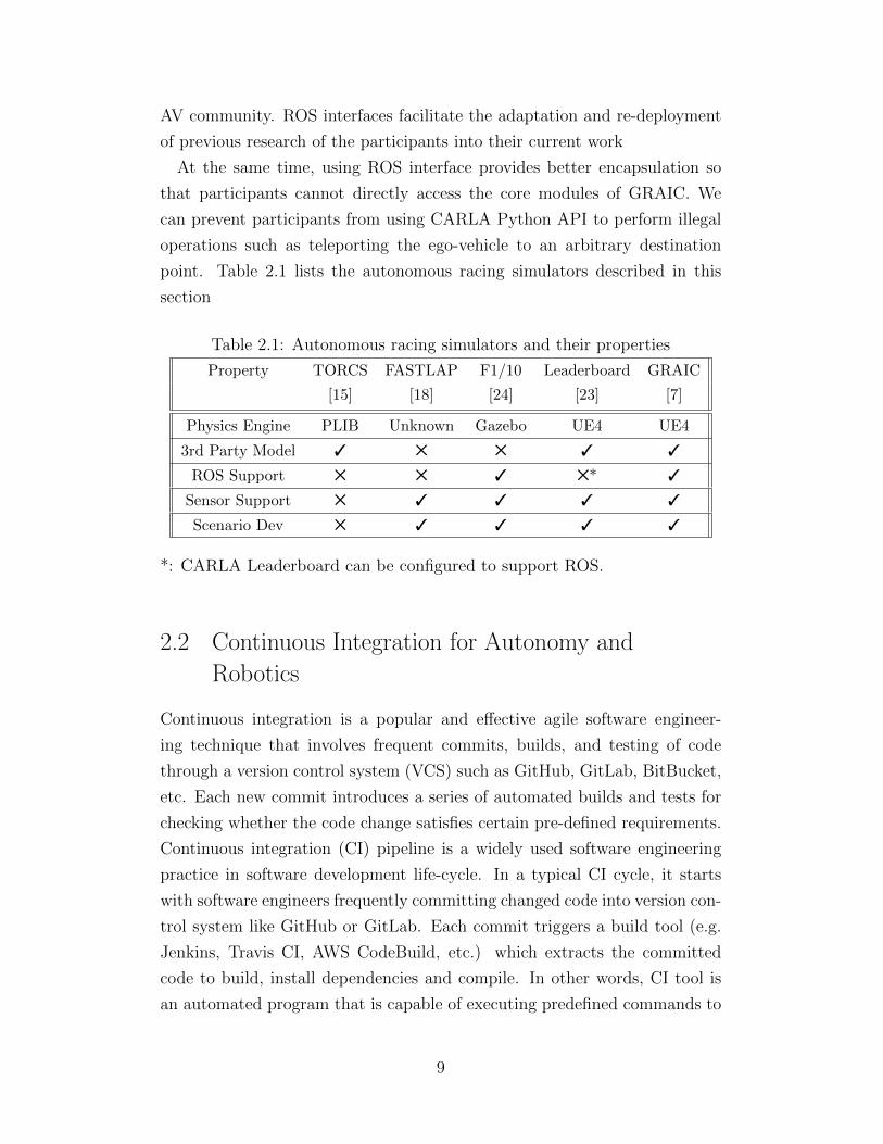
point. Table 2.1 lists the autonomous racing simulators described in this
section
Table 2.1: Autonomous racing simulators and their properties
Property TORCS FASTLAP F1/10 Leaderboard GRAIC
[15] [18] [24] [23] [7]
Physics Engine PLIB Unknown Gazebo UE4 UE4
3rd Party Model 3 5 5 3 3
ROS Support 5 5 3 5* 3
Sensor Support 5 3 3 3 3
Scenario Dev 5 3 3 3 3
*: CARLA Leaderboard can be configured to support ROS.
2.2 Continuous Integration for Autonomy and
Robotics
Continuous integration is a popular and effective agile software engineer-
ing technique that involves frequent commits, builds, and testing of code
through a version control system (VCS) such as GitHub, GitLab, BitBucket,
etc. Each new commit introduces a series of automated builds and tests for
checking whether the code change satisfies certain pre-defined requirements.
Continuous integration (CI) pipeline is a widely used software engineering
practice in software development life-cycle. In a typical CI cycle, it starts
with software engineers frequently committing changed code into version con-
trol system like GitHub or GitLab. Each commit triggers a build tool (e.g.
Jenkins, Travis CI, AWS CodeBuild, etc.) which extracts the committed
code to build, install dependencies and compile. In other words, CI tool is
an automated program that is capable of executing predefined commands to
9

compile and run software. Then, CI tool executes predefined unit or integra-
tion tests to locate bugs that violates the conditions configured in these tests.
In this way, if bugs are introduced in any commits, it is easier for software
engineers to locate the commits, debug, and possibly rollback to the previous
bug-free version.
Continuous integration has been used in robotics in recent years. A typical
example is the ROS Build Farm [25] which is capable of performing release
builds and provides hosting of ROS official packages. Basically, submitted
ROS packages to ROS Build Farm are compiled and packaged for release.
In the industry, AV companies have their own tool for continuous integra-
tion and deployment. While most companies keep the CI tool confidential as
an internal property, AImotive shared its automated CI pipeline in a white
paper by Pinter and Engelstein [26]. The pipeline is a complete cycle of AV
development with stages of automated tests: Unit test, Module test, Scenario
test, Vehicle Integration test. Among these tests, the Module and Scenario
tests happen in AImotive’s simulation tool called aiSim. According to [26],
testing through scenarios is crucial to the overall pipeline and scenario test-
ing must preserve the determinism property. This thesis will present how we
managed to resolve the determinism problem in our testing pipeline.
The continuous integration testing pipeline introduced in this thesis also
uses a simulator as the testing medium. Serving as the backend of GRAIC,
our testing pipeline focuses on testing the decision and controller module
as an end-to-end system using scenarios. Our testing pipeline also has the
ability to do verification using reachability analysis tools.
2.3 Generating Scenarios for Testing
In testing autonomous vehicles, scenario-based testing has been used in sev-
eral different ways. Common scenario generation approaches can be divided
into two main categories: (1) event-based and (2) data-based.
The event-based methods generate scenarios according to pre-defined traf-
fic elements such as lanes, vehicles, pedestrian, accidents, etc. In [27], re-
searchers use behavior trees structure to plan decisions and create scenarios.
Behavior tree is a type of mathematical model used for execution planning.
It describes control flow and task switching among a finite set of states which
10
works similarly to a finite state machine.
In [28], the authors implement a convolutional neural network (CNN)
based scenario generation pipeline that can be triggered by the AV. Once the
ego-vehicle enters the generation area, the CNN then selects an adversarial
agent and corresponding actions to react to the behavior of the ego-vehicle.
In terms of data-based scenario generation approach, scenarios are gener-
ated based on real driving data. In [29], after analyzing 19,000 hours of data
of real car accidents including vehicle trajectories, speeds and pedestrian be-
havior, the researchers generated 18 different scenarios representing the most
frequent accidents involving pedestrians.
Feng et al [30] pointed out the lack of spatiotemporal complexity of most
existing scenario generation methods, namely, that they can only generate
scenarios involving limited number of vehicles in short duration. To tackle
this issue, these researchers first created a driving simulator that allows AVs
to drive continuously along the test track. Then, they proposed a reinforce-
ment learning based approach that analyzes the vehicle maneuvers when
encountering obstacles and proposed adversarial behaviors or commands to
other vehicle agents.
In the study by van der Made et al. [31], driving data is recorded from
sensors like laser sensors installed on real cars. These driving data can be
post-processed to identify other vehicles and pedestrians, and scenarios can
be constructed based on the captured information. Computer vision tech-
niques are often used to process images captured on physical vehicles driving
on the real road. Park et al. [32] present the use of Faster-RCNN to detect
and extract objects from driving video and to sort the objects into bounding
boxes. Then, they use LRCN to perform event or scenario generation.
2.4 Formal Verification for Simulation Models
Formal verification of cyber-physical systems has received significant atten-
tion over the last three decades [33]. While the goal of testing is to find design
bugs, verification aims to prove that the system meets some requirements,
such as safety and stability. Verification algorithms have traditionally re-
quired explicit mathematical models of the system, and therefore, would not
be applicable to systems described by software simulators such as the ones
11
we have discussed earlier in this section. As autonomous vehicles are com-
plex and heterogeneous, and lack complete mathematical models for many
of their components, there is a growing interest in verification methods that
can work with incomplete or black-box models. In this section, we present
an overview of these emerging techniques.
The DryVR project and the associated tools [34, 35] can verify gray-box
models in which some of the system components are described using white-
box mathematical models, while others are described using black-box sim-
ulators. Traditional verification approaches, like fixed-point analysis and
abstractions, are used for the white-box parts of the model, and sensitivity
analysis is used for the black-box parts [36, 27, 37, 38]. This type of analy-
sis provides a probabilistic guarantee (Probably Approximately Correct) for
the sensitivity analysis, and assuming that the learned sensitivity function
is correct, it gives a deterministic (worst-case) guarantee on safety. The
approach has been used to verify safety of Automatic Emergency Braking
(AEB) systems [39], aircraft landing protocols [40], and powertrain control
systems [41].
Creation of complex scenarios with interacting agents, for the purposes
of verification, is still in its infancy. The Scenic project [42] proposes a
probabilistic programming language named Scenic to define scenarios over
scenes, configuration over vehicles and other agents. Scenic supports multiple
simulator environments including CARLA [9], GTA V [12], and LGSVL [11].
Scalability of verifying complex scenarios is a persistent challenge, and the
recent results show the promise of exploiting the underlying symmetries of
the scenario [43, 44, 45].
Adaptive Stress Testing (AST) is another type of simulation-based ver-
ification method for AV. It involves using reinforcement learning to search
through scenario spaces to find the most likely failures. Corso et al. [46] pro-
pose improvements to the AST by adding 2 types of reward augmentation.
One uses the Responsibility Sensitive Safety (RSS) policy in the reward func-
tion; the other involves using dissimilarity metric to identify unique modes
of failure. The results showed, through the reward augmentation, that AST
is capable of finding more diverse and useful failures that can facilitate the
validation of AV
12

2.5 Summary
In this chapter, we summarized related works on simulated autonomous rac-
ing competition, continuous integration in AV, and testing and formal verifi-
cation for simulation models. This related work motivates us to apply contin-
uous integration technique and scenario testing to evaluate AVs in GRAIC.
In Chapter 3, we present the details of our simulated autonomous racing
framework, GRAIC, and how we create the testing pipeline to evaluate the
performance of AVs in GRAIC. Then, in Chapter 4, we present a scenario
generation algorithm to illustrate how scenarios are created for GRAIC.
13

CHAPTER 3
AUTONOMOUS RACING TESTINGPIPELINE
In this chapter, we first present the GRAIC framework [7], which is a soft-
ware framework for autonomous vehicle racing simulations. Then, we present
Autonomous System Operations (AutOps) a continuous integration (CI) and
testing framework for automatically evaluating vehicle controllers for GRAIC.
Determinism of tests is a crucial property for simulation-based AV testing.
We demonstrate that AutOps preserves determinism within an acceptable
error range. Finally, we evaluate the performance of AutOps.
3.1 GRAIC Framework
GRAIC is a software framework for autonomous racing competitions. Par-
ticipants create controller functions that drive an ego-vehicle in different
simulated race tracks with active and passive obstacles, and pass through
a series of milestones. During this process, GRAIC also evaluates the ego-
vehicle by generating a score for benchmarking. The score that the vehicle
receives from a track depends on both safety and the completion time.
GRAIC is developed based on CARLA Simulator (CARLA) [9] and Robot
Operating System (ROS) [47]. The latest release uses CARLA 0.9.11 and
ROS Noetic. The participants need to develop their controller to communi-
cate with GRAIC using ROS interfaces defined by rostopics.
Figure 3.1 shows the higher level architecture of GRAIC. This competition
focuses on racing strategy, decision, and control, and not on perception.
Because of this focus, we provide a perception oracle that outputs ground
truth perception results. Then, it delivers this information through rostopics
to the Decision and Control module which contains the controller code that
participants submit. This module is also the key component that GRAIC
attempts to evaluate. Participants’ submitted controller code then produces
14

Figure 3.1: The architecture of GRAIC framework.
control input for the Actuation module in which participants can choose
different vehicle models to apply their control on.
3.1.1 Perception Oracle
GRAIC’s perception oracle periodically outputs ground-truth object detec-
tion results in the neighborhood of the ego vehicle as shown in Figure 3.1.
The notion of a perception oracle for controller synthesis research was intro-
duced by Miller et al. [48]. A perception oracle outputs a local view of the
surrounding environment that is within a certain distance of the ego-vehicle.
Among its functions are the following:
Obstacles The obstacles are actors in CARLA simulator such as vehicles,
cyclists, and pedestrian other than the ego vehicle. The perception oracle
gives the precise locations and a bounding box of the obstacles
rostopic: /carla/ego vehicle/obstacles
Lane Information The perception oracle provides road lane information
for the ego-vehicle by outputting a list of the points that are on the lane. The
ego-vehicle can also know which one of the three lanes that it is currently on.
rostopic: /carla/ego vehicle/lane markers
Location The ego-vehicle can obtain its current global position, orienta-
tion, and velocity through the perception oracle.
15
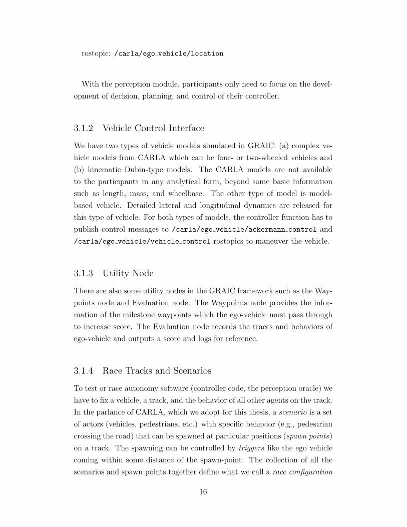
rostopic: /carla/ego vehicle/location
With the perception module, participants only need to focus on the devel-
opment of decision, planning, and control of their controller.
3.1.2 Vehicle Control Interface
We have two types of vehicle models simulated in GRAIC: (a) complex ve-
hicle models from CARLA which can be four- or two-wheeled vehicles and
(b) kinematic Dubin-type models. The CARLA models are not available
to the participants in any analytical form, beyond some basic information
such as length, mass, and wheelbase. The other type of model is model-
based vehicle. Detailed lateral and longitudinal dynamics are released for
this type of vehicle. For both types of models, the controller function has to
publish control messages to /carla/ego vehicle/ackermann control and
/carla/ego vehicle/vehicle control rostopics to maneuver the vehicle.
3.1.3 Utility Node
There are also some utility nodes in the GRAIC framework such as the Way-
points node and Evaluation node. The Waypoints node provides the infor-
mation of the milestone waypoints which the ego-vehicle must pass through
to increase score. The Evaluation node records the traces and behaviors of
ego-vehicle and outputs a score and logs for reference.
3.1.4 Race Tracks and Scenarios
To test or race autonomy software (controller code, the perception oracle) we
have to fix a vehicle, a track, and the behavior of all other agents on the track.
In the parlance of CARLA, which we adopt for this thesis, a scenario is a set
of actors (vehicles, pedestrians, etc.) with specific behavior (e.g., pedestrian
crossing the road) that can be spawned at particular positions (spawn points)
on a track. The spawning can be controlled by triggers like the ego vehicle
coming within some distance of the spawn-point. The collection of all the
scenarios and spawn points together define what we call a race configuration
16
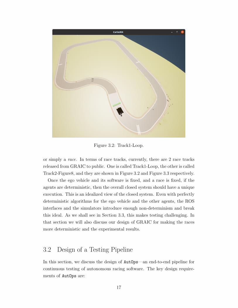
Figure 3.2: Track1-Loop.
or simply a race. In terms of race tracks, currently, there are 2 race tracks
released from GRAIC to public. One is called Track1-Loop, the other is called
Track2-Figure8, and they are shown in Figure 3.2 and Figure 3.3 respectively.
Once the ego vehicle and its software is fixed, and a race is fixed, if the
agents are deterministic, then the overall closed system should have a unique
execution. This is an idealized view of the closed system. Even with perfectly
deterministic algorithms for the ego vehicle and the other agents, the ROS
interfaces and the simulators introduce enough non-determinism and break
this ideal. As we shall see in Section 3.3, this makes testing challenging. In
that section we will also discuss our design of GRAIC for making the races
more deterministic and the experimental results.
3.2 Design of a Testing Pipeline
In this section, we discuss the design of AutOps—an end-to-end pipeline for
continuous testing of autonomous racing software. The key design require-
ments of AutOps are:
17
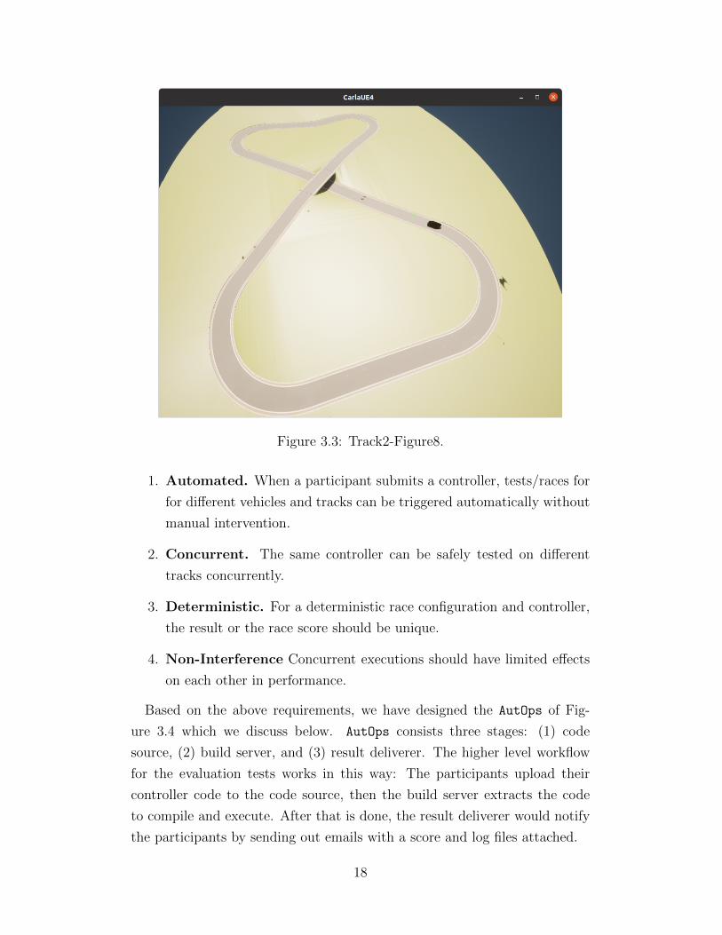
Figure 3.3: Track2-Figure8.
1. Automated. When a participant submits a controller, tests/races for
for different vehicles and tracks can be triggered automatically without
manual intervention.
2. Concurrent. The same controller can be safely tested on different
tracks concurrently.
3. Deterministic. For a deterministic race configuration and controller,
the result or the race score should be unique.
4. Non-Interference Concurrent executions should have limited effects
on each other in performance.
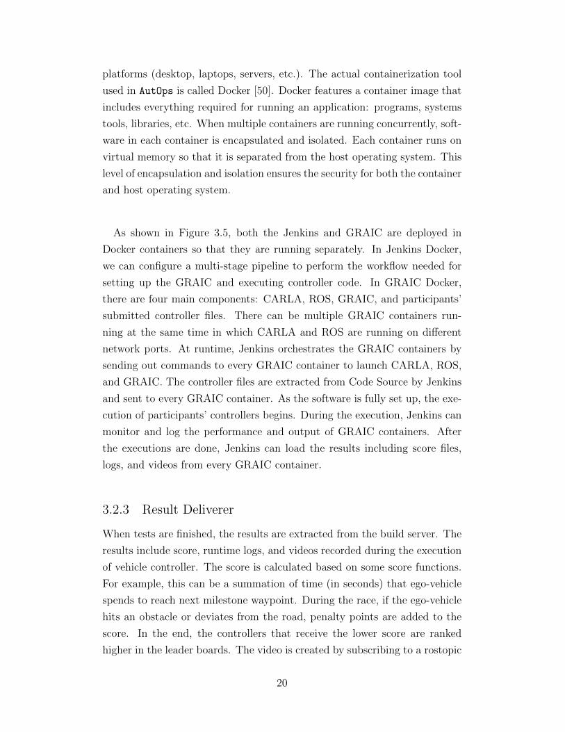
Based on the above requirements, we have designed the AutOps of Fig-
ure 3.4 which we discuss below. AutOps consists three stages: (1) code
source, (2) build server, and (3) result deliverer. The higher level workflow
for the evaluation tests works in this way: The participants upload their
controller code to the code source, then the build server extracts the code
to compile and execute. After that is done, the result deliverer would notify
the participants by sending out emails with a score and log files attached.
18
3.2.1 Code Source
In our design, the code source is developed by using cloud services from
Amazon Web Services (AWS). As shown in Figure 3.4, Code Source is the
block on the left which contains AWS S3 Storage and AWS Lambda. AWS
S3 is a cloud storage that can store participants’ submitted controller files.
AWS Lambda is a serverless computing service that can execute computer
programs without provisioning and managing servers. An important fea-
ture of AWS S3 is that once controller files are uploaded to the storage by
participants, AWS S3 can trigger the AWS Lambda containing a Python
program which sends HTTP request to notify our Build Server to extract
controller files and perform further steps to test them. In this way, the tests
can automatically start once a controller file is submitted.
3.2.2 Build Server
The build server is the heart of AutOps and is responsible for creating com-
plete executable containers for each race. Before diving deeply into the build
server, we explain the two important software engineering techniques that
are used in the development: continuous integration and containerization.
Continuous Integration Recall from Section 2.2 that continuous integra-
tion is a software engineering technique where software developers commit
code changes frequently to a version control system like GitHub, and each
commit would trigger a number of automated builds and tests for checking
whether the code change satisfies certain pre-defined requirements. This no-
tion of continuous integration inspires the design of AutOps, as the higher
level workflow of controller submission in GRAIC is very similar. In AutOps,
the continuous integration tool is called Jenkins [49], which can execute a set
of user-defined commands automatically.
Containerization is a type of software virtualization similar to virtual ma-
chine. Software applications are running in isolated computing units called
containers. Inside the container, programs and dependencies are packaged
so that the container can be quickly and reliably run across different host-
ing operating systems (Linus, Window, MacOS, etc.) on different hardware
19
platforms (desktop, laptops, servers, etc.). The actual containerization tool
used in AutOps is called Docker [50]. Docker features a container image that
includes everything required for running an application: programs, systems
tools, libraries, etc. When multiple containers are running concurrently, soft-
ware in each container is encapsulated and isolated. Each container runs on
virtual memory so that it is separated from the host operating system. This
level of encapsulation and isolation ensures the security for both the container
and host operating system.
As shown in Figure 3.5, both the Jenkins and GRAIC are deployed in
Docker containers so that they are running separately. In Jenkins Docker,
we can configure a multi-stage pipeline to perform the workflow needed for
setting up the GRAIC and executing controller code. In GRAIC Docker,
there are four main components: CARLA, ROS, GRAIC, and participants’
submitted controller files. There can be multiple GRAIC containers run-
ning at the same time in which CARLA and ROS are running on different
network ports. At runtime, Jenkins orchestrates the GRAIC containers by
sending out commands to every GRAIC container to launch CARLA, ROS,
and GRAIC. The controller files are extracted from Code Source by Jenkins
and sent to every GRAIC container. As the software is fully set up, the exe-
cution of participants’ controllers begins. During the execution, Jenkins can
monitor and log the performance and output of GRAIC containers. After
the executions are done, Jenkins can load the results including score files,
logs, and videos from every GRAIC container.
3.2.3 Result Deliverer
When tests are finished, the results are extracted from the build server. The
results include score, runtime logs, and videos recorded during the execution
of vehicle controller. The score is calculated based on some score functions.
For example, this can be a summation of time (in seconds) that ego-vehicle
spends to reach next milestone waypoint. During the race, if the ego-vehicle
hits an obstacle or deviates from the road, penalty points are added to the
score. In the end, the controllers that receive the lower score are ranked
higher in the leader boards. The video is created by subscribing to a rostopic
20
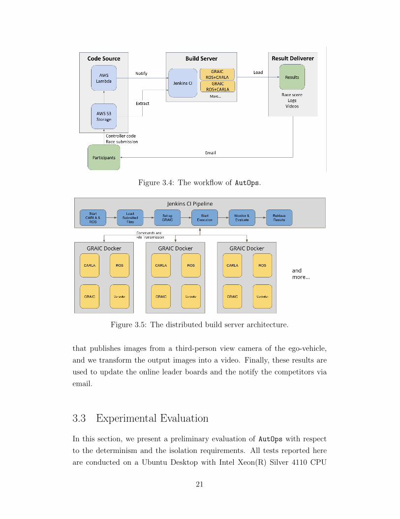
Figure 3.4: The workflow of AutOps.
Figure 3.5: The distributed build server architecture.
that publishes images from a third-person view camera of the ego-vehicle,
and we transform the output images into a video. Finally, these results are
used to update the online leader boards and the notify the competitors via
email.
3.3 Experimental Evaluation
In this section, we present a preliminary evaluation of AutOps with respect
to the determinism and the isolation requirements. All tests reported here
are conducted on a Ubuntu Desktop with Intel Xeon(R) Silver 4110 CPU
21

(2.10GHz), 32 GB RAM, and Nvidia Quadro P5000 GPU (16 GB).
3.3.1 More Deterministic Races
The determinism of testing is especially crucial to the overall quality of the
testing result. A test is called deterministic if, under the same environment
and testing configuration, the results are reproducible. If the testing results
are not repeatable, it is extremely difficult to determine the root cause of
certain failures in the autonomous driving system. Without determinism,
the race winner may not be determinable or the results may be unfair.
In our initial implementation of GRAIC, the races were far from determin-
istic because the spawning of scenarios was randomized, and the start-ups of
the controller, the CARLA simulator, and the ROS nodes were not synchro-
nized. Towards having more deterministic races, we have taken the following
measures:
• We configure ROS and CARLA to run in synchronous mode by setting
the ROS to be the only CARLA client that could perform the tick()
operation for advancing simulation time. This minimizes error caused
by the delay of control input transported over ROS networks.
• We use bash scripts to ensure that the initiation of the above modules
is done in the exact order and that the controller code is started at the
same state in the environment.
• We use CARLA scenario runner [8] framework to customize the trig-
gering of scenarios. Each scenario is triggered when the ego-vehicle ap-
proaches a spawn point on the tracks. The scenario tests are initiated
when the ego-vehicle approaches pre-defined scenario trigger points on
the race tracks of GRAIC. In this way, the stochasticity is reduced
significantly.
Results We tested AutOps running the GRAIC with the two tracks and two
types of vehicles. For each of these four races we look at results both before
and after applying the determinism settings described above. The obstacle in
these tests is another vehicle that moves forward with a constant speed. For
testing before applying determinism settings, the obstacle vehicle can appear
22
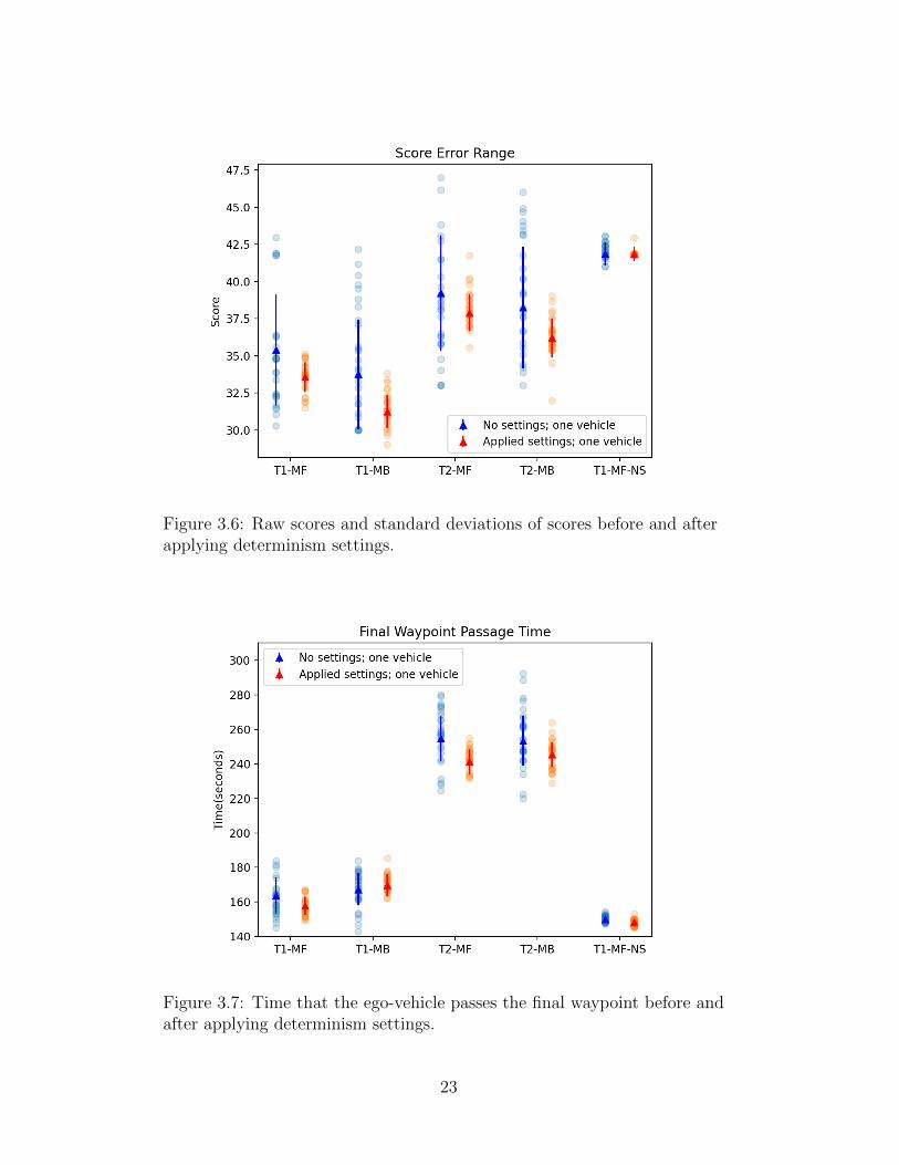
Figure 3.6: Raw scores and standard deviations of scores before and afterapplying determinism settings.
Figure 3.7: Time that the ego-vehicle passes the final waypoint before andafter applying determinism settings.
23
anywhere along the track. In contrast, for testing after applying determinism
settings, the vehicle starts to move when the ego vehicle approaches within a
certain fixed distance. This gives us four race configurations: Track1 CARLA
vehicle (T1-MF), Track1 kinematic vehicle (T1-MB), Track2 CARLA vehicle
(T2-MF), Track2 kinematic vehicle (T2-MB). In addition, we have a fifth race
configuration without obstacles on the track (T1-NS).
Using AutOps we ran 28 tests with a baseline vehicle controller, on each
these five configurations, both before and after applying the determinism
settings. CPU usage across different races stayed between 30-35% and the
average memory usage was around 4.5%. The collected scores and race com-
pletion times are shown in Figures 3.6 and 3.7. It is clear from these plots
that the measures taken above make the races more deterministic. On aver-
age, the standard deviation of the score is decreased by 70% across the board.
We also observe that the races with fewer collisions are more deterministic;
an extreme version of this is the fifth race (T1-NS).
Discussion We believe that the remaining variations in the tests have two
contributing factors, and we do not see a clear remedy for either:
(1) ROS’s TCP/IP-based messaging. The delay in transmission of packets
can result in the actuator receiving control inputs at slightly different times-
tamps; eventually, it leads to discrepancy in the behavior of ego-vehicle.
(2) Non-determinism introduced by collisions and contact [51]. Every time
the ego-vehicle collides with an obstacle in a given race configuration, the
outcome can be different. As shown in Figures 3.6 and 3.7, the standard
deviation with the race with no collisions is the smallest. These two sources
of non-determinism are likely to bedevil future autonomous racing competi-
tions.
3.3.2 Interference across Concurrent Instances
In order to study the non-interference requirement of AutOps, we have con-
ducted another set of experiments. First, we run ten races on the same race
configuration with Track 1 with a single obstacle. Then, we run two instances
of the race. Continuing in this way, we run up to five concurrent race in-
stances. For each of these experiments, we only report the results (score) of
the first race and the total CPU usage. The results are shown on Figure 3.8.
24
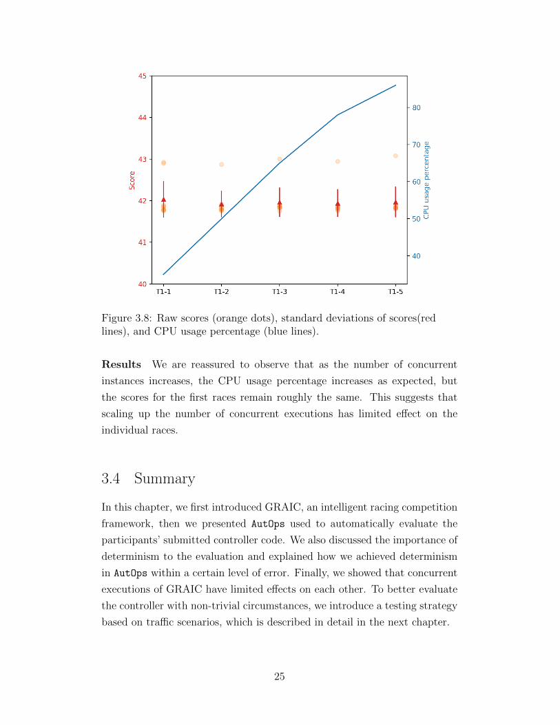
Figure 3.8: Raw scores (orange dots), standard deviations of scores(redlines), and CPU usage percentage (blue lines).
Results We are reassured to observe that as the number of concurrent
instances increases, the CPU usage percentage increases as expected, but
the scores for the first races remain roughly the same. This suggests that
scaling up the number of concurrent executions has limited effect on the
individual races.
3.4 Summary
In this chapter, we first introduced GRAIC, an intelligent racing competition
framework, then we presented AutOps used to automatically evaluate the
participants’ submitted controller code. We also discussed the importance of
determinism to the evaluation and explained how we achieved determinism
in AutOps within a certain level of error. Finally, we showed that concurrent
executions of GRAIC have limited effects on each other. To better evaluate
the controller with non-trivial circumstances, we introduce a testing strategy
based on traffic scenarios, which is described in detail in the next chapter.
25

CHAPTER 4
CREATING SCENARIOS FOR TESTING
In order to perform simulation-based testing of an autonomous driving sys-
tem, we need to create realistic driving situations or scenarios in the simula-
tor. This chapter illustrates how we utilized CARLA’s scenario runner [8] to
create a dynamic scenario generator and how we evaluate the performance
of the vehicle controller in these scenarios.
4.1 Testing using Scenario Runner
To evaluate a candidate controller for GRAIC, we have developed a scenario
testing framework as a part of our testing pipeline based on CARLA’s sce-
nario runner. The CARLA scenario runner was used in the CARLA Leader-
board [23] to create traffic scenarios to increase the complexity of the com-
petition.
In scenario runner, scenarios are defined as Python classes as shown in
Listing 1. We can also define the configurations of obstacle vehicles or pedes-
trians and their behaviors. The Bad Merge scenario, for example, which we
used in Chapter 3, is declared in this way. In the Scenario class, there are 2
methods that need to be implemented. The first one is the initialize actors
method in which we can initialize the other obstacle actors (vehicles or pedes-
trian) at a certain location as an argument. Then, inside the create behavior
method, we can define the behaviors for the other actors to make the sce-
narios more interesting. The behaviors include but are not limited to setting
the actor to cruise with maximum speed (ChangeAutoPilot), keeping the
actor moving at a constant speed (KeepVelocity), making the vehicle change
lanes (ChangeLane), etc. These behaviors can be added to a behavior tree
object called Sequence from Py Trees [52], which is a Python library creating
behavior trees for robotics and games. Then, the behaviors are executed by
26
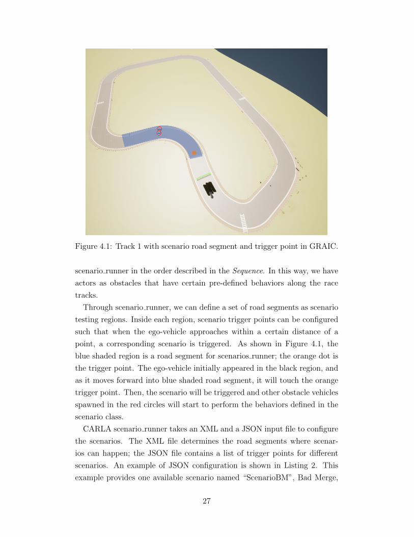
Figure 4.1: Track 1 with scenario road segment and trigger point in GRAIC.
scenario runner in the order described in the Sequence. In this way, we have
actors as obstacles that have certain pre-defined behaviors along the race
tracks.
Through scenario runner, we can define a set of road segments as scenario
testing regions. Inside each region, scenario trigger points can be configured
such that when the ego-vehicle approaches within a certain distance of a
point, a corresponding scenario is triggered. As shown in Figure 4.1, the
blue shaded region is a road segment for scenarios runner; the orange dot is
the trigger point. The ego-vehicle initially appeared in the black region, and
as it moves forward into blue shaded road segment, it will touch the orange
trigger point. Then, the scenario will be triggered and other obstacle vehicles
spawned in the red circles will start to perform the behaviors defined in the
scenario class.
CARLA scenario runner takes an XML and a JSON input file to configure
the scenarios. The XML file determines the road segments where scenar-
ios can happen; the JSON file contains a list of trigger points for different
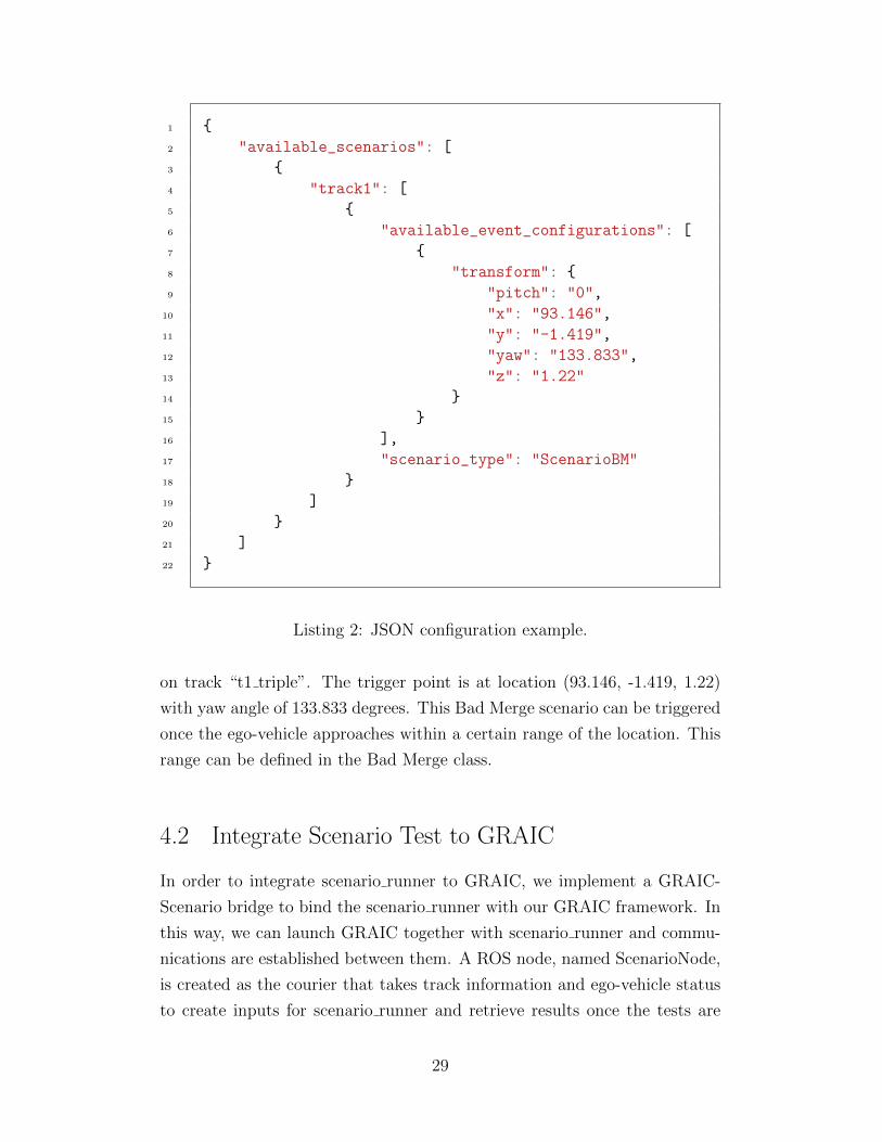
scenarios. An example of JSON configuration is shown in Listing 2. This
example provides one available scenario named “ScenarioBM”, Bad Merge,
27

1 class BadMerge:
2 def initialize_actors(self, spawn_point):
3 """
4 initialize other vehicles or pedestrians
5 """
6 self.other_vehicle = create_new_actor(spawn_point)
7 self.other_vehicle.set_physics(True)
8
9 def create_behavior(self):
10 """
11 Setup the behavior for BadMerge
12 """
13 # Create a Sequence() behavior
14 bad_merge = Sequence()
15 #
16 bad_merge.add_child(
17 InTriggerDistanceToVehicle(self.other_vehicle,
18 self.ego_vehicles,
19 distance=70,
20 name="Distance")
21 )
22
23 bad_merge.add_child(
24 ChangeAutoPilot(self.other_vehicle, True,
25 parameters={"max_speed": 20})
26 )
27
28 bad_merge.add_child(
29 KeepVelocity(self.other_vehicle, 20)
30 )
Listing 1: Python class for scenario Bad Merge.
28
1 {
2 "available_scenarios": [
3 {
4 "track1": [
5 {
6 "available_event_configurations": [
7 {
8 "transform": {
9 "pitch": "0",
10 "x": "93.146",
11 "y": "-1.419",
12 "yaw": "133.833",
13 "z": "1.22"
14 }
15 }
16 ],
17 "scenario_type": "ScenarioBM"
18 }
19 ]
20 }
21 ]
22 }
Listing 2: JSON configuration example.
on track “t1 triple”. The trigger point is at location (93.146, -1.419, 1.22)
with yaw angle of 133.833 degrees. This Bad Merge scenario can be triggered
once the ego-vehicle approaches within a certain range of the location. This
range can be defined in the Bad Merge class.
4.2 Integrate Scenario Test to GRAIC
In order to integrate scenario runner to GRAIC, we implement a GRAIC-
Scenario bridge to bind the scenario runner with our GRAIC framework. In
this way, we can launch GRAIC together with scenario runner and commu-
nications are established between them. A ROS node, named ScenarioNode,
is created as the courier that takes track information and ego-vehicle status
to create inputs for scenario runner and retrieve results once the tests are
29

completed.
As introduced in Section 4.1, scenario runner uses XML and JSON files to
load information about where the scenarios are triggered. The road segments
and trigger points are hardcoded into these files. In order to generate scenar-
ios in a more flexible fashion, we alternate the input and output interfaces by
implementing a ScenarioArguments class that takes Python data structures
like HashMap and List rather than configuration files. For example, instead
of using JSON file, we use HashMap to represent the trigger point infor-
mation of any scenario. Moreover, we use milestone waypoints to configure
the road segments, trigger points, and spawning points for other vehicles or
pedestrians.
We also apply some other modifications to the scenario runner so that it
does not affect the normal execution flow of GRAIC. In the original sce-
nario runner, it creates an ego-vehicle at the beginning of a scenario and
deletes it once the scenario finished. However, this feature is not needed and
should be removed; otherwise, the GRAIC competition is affected. After
our modifications, we ensure that scenario runner does not have any ma-
nipulation over the ego-vehicle and does not affect the determinism of the
GRAIC.
4.3 Scenario Generation Strategy
After integrating scenario runner to GRAIC, we propose an intelligent sce-
nario generation strategy. In our implementation, we keep a list of available
scenarios which are divided into two categories: unit scenarios and compos-
ite scenarios. Unit scenarios are fine-grained traffic situations that usually
involve only a single obstacle agent with one type of behavior. A pedes-
trian crossing the road or an obstacle vehicle suddenly stopping ahead are
examples of unit scenarios.
As for the composite scenarios, they are created by using “scenario oper-
ations” over unit scenarios. Here, we defined three types of scenario opera-
tions: Merge, Stack, and “Symmetricalify”. The composite scenarios can be
generated by merging, stacking, or “symmetricalifying” the unit scenarios.
Suppose there are two unit scenarios A and B. Scenario A is a situation
where a pedestrian attempts to cross the road from the right side of the road,
30

Figure 4.2: Scenario A: A pedestrian attempts to cross the road from theright side of the road.
as shown in Figure 4.2. Scenario B is a situation where a vehicle suddenly
stops when the ego-vehicle approaches from the back, as shown in Figure 4.3.
Then, the scenario operations can be interpreted in the following way:
• Merge (A + B): an obstacle vehicle in the front suddenly stops when
a pedestrian attempts to cross the road from the right side of the road
• Stack (2 * A): two obstacle vehicles in the front suddenly stop
• Symmetricalify (Sym(B)): a pedestrian attempts to cross the road from
the left side of the road
An example of the composite scenario created by merging Scenario A and
B is shown in Figure 4.4. This image shows that an obstacle vehicle suddenly
stops ahead when a pedestrian attempts to cross the road from the right side
of the road
As we define the two types of scenarios in our context, we also develop a
dynamic scenario generation algorithm that takes the results from previous
unit scenarios to dynamically generate composite scenarios along the race
track of GRAIC.
31
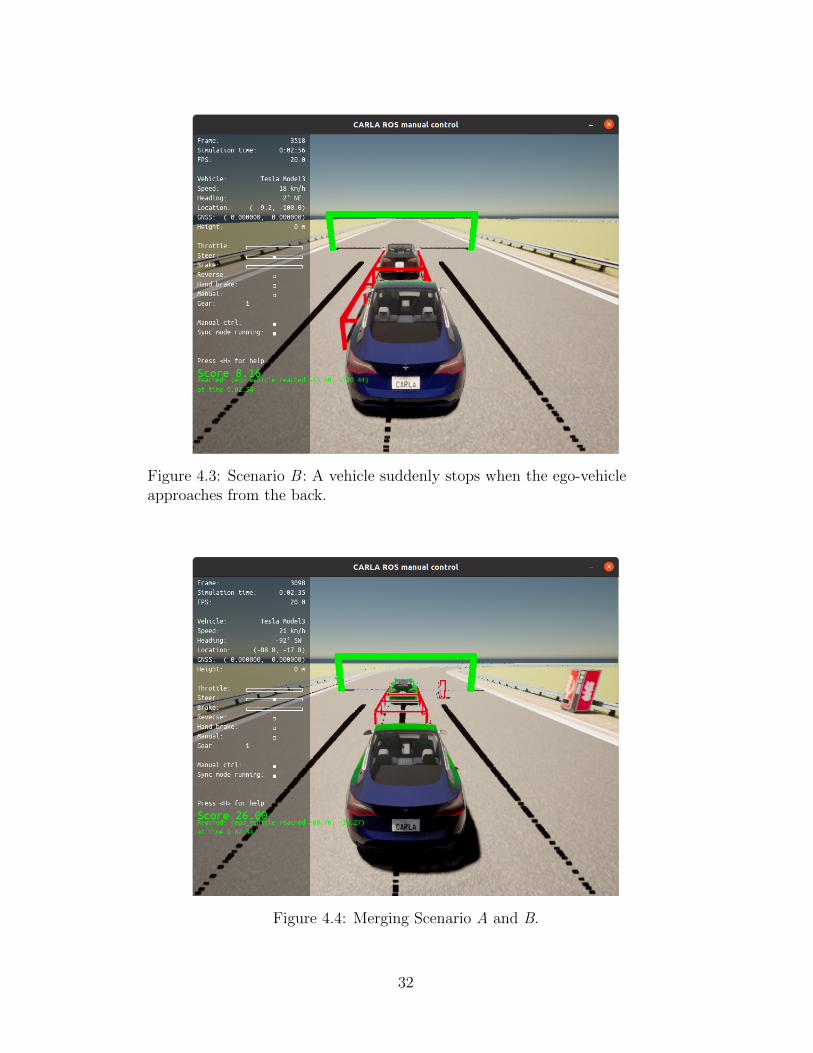
Figure 4.3: Scenario B : A vehicle suddenly stops when the ego-vehicleapproaches from the back.
Figure 4.4: Merging Scenario A and B.
32
The race tracks are divided into two sections: the first section has unit
scenarios while the second section has composite scenarios. Initially, all the
unit scenarios are mapped to the first section of the track, and as the ego-
vehicle passes through each unit scenario, the result is recorded. The ego-
vehicle may succeed in some unit scenarios but fail on the others. These
results will affect how we generate the composite scenarios in the second
section of the track.
One heuristic for composite scenario generation is that if the vehicle fails
any of the unit scenarios, we exclude those failed unit scenarios and the
composite scenarios that contain the failed unit scenarios. The reason for this
operation is based on the fact that the purpose of our evaluation mechanism is
to detect as many design failure and flaw in the vehicle controller as possible.
The algorithm is not attempting its best to simply reduce the score of the
vehicle controller. If the algorithm is only trying to minimize the score, it
can simply reuse the first failed scenario all the time. However, in this way,
we can only detect the issue exposed by the one failed scenario and unable
to explore more. Therefore, under this consideration, if the vehicle fails a
scenario, we can conclude that there are bugs in the vehicle controller. It
is not necessary to use the same scenario or composite scenarios built upon
the same scenario to test the vehicle again. On the other hand, since AutOps
preserves the determinism property, testing the vehicle controller against the
same scenarios should produce very a similar result. This is implemented in
the Algorithm 1.
Initially, the GenerateScenario() function keeps a list of unit scenarios,
stored in the local variable ScenarioList. This function takes a variable
named previousResult as input, which contains information about how ego-
vehicle behaves in a unit scenario in the first section of the track. This
variable can be None meaning that it is the first time we call this function.
In this way, GenerateScenario() returns a unit scenario from the Scenari-
oList. Note that this unit scenario is marked as used. If previousResult is
defined, we need to update the composite scenarios from ScenarioList. If the
ego-vehicle fails on the unit scenario, then based on the heuristic, we remove
the corresponding unit scenario from ScenarioList. This is done through
ScenarioList.update() method. Based on the different scenario generation
heuristics, this function can also be changed. At this point, we also need to
see if there are any unit scenarios remaining in the ScenarioList. If there are,
33
it outputs a unit scenario and marks it as used. If not, a composite scenario
is created based on the remaining unit scenarios in ScenarioList. This step
is defined in the scenarioList.getCompositeScenario().
GenerateScenario();
input : previousResult
output: scenario
initialization;
scenarioList() = [/* List of Available Scenarios */];
if previousResult == None then
scenario = scenarioList.getUnitScenario();
else
scenarioList.update(PreviousResult);
if scenarioList.hasUnitScenario() then
scenario = scenarioList.getUnitScenario();
else
scenario = scenarioList.getCompositeScenario();
end
end
return scenario;Algorithm 1: GenerateScenario function
The ScenarioNode shown in Algorithm 2 is the main thread of our scenario
testing framework. It keeps track of the ego-vehicle status and results from
already executed scenarios and calls the GenerateScenario function to acquire
new scenarios. Then, based on the status of ego-vehicle and the generated
scenario, a function named GenerateScenarioConfig is used for creating the
configurations that are loaded to CARLA scenario runner. Then, it waits
for the completion of scenario runner to produce results. Finally, results
are recorded and once the GRAIC competition is finished, they are sent to
EvaluationNode to be analyzed for score generation.
34
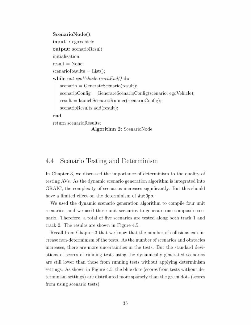
ScenarioNode();
input : egoVehicle
output: scenarioResult
initialization;
result = None;
scenarioResults = List();
while not egoVehicle.reachEnd() do
scenario = GenerateScenario(result);
scenarioConfig = GenerateScenarioConfig(scenario, egoVehicle);
result = launchScenarioRunner(scenarioConfig);
scenarioResults.add(result);
end
return scenarioResults;Algorithm 2: ScenarioNode
4.4 Scenario Testing and Determinism
In Chapter 3, we discussed the importance of determinism to the quality of
testing AVs. As the dynamic scenario generation algorithm is integrated into
GRAIC, the complexity of scenarios increases significantly. But this should
have a limited effect on the determinism of AutOps.
We used the dynamic scenario generation algorithm to compile four unit
scenarios, and we used these unit scenarios to generate one composite sce-
nario. Therefore, a total of five scenarios are tested along both track 1 and
track 2. The results are shown in Figure 4.5.
Recall from Chapter 3 that we know that the number of collisions can in-
crease non-determinism of the tests. As the number of scenarios and obstacles
increases, there are more uncertainties in the tests. But the standard devi-
ations of scores of running tests using the dynamically generated scenarios
are still lower than those from running tests without applying determinism
settings. As shown in Figure 4.5, the blue dots (scores from tests without de-
terminism settings) are distributed more sparsely than the green dots (scores
from using scenario tests).
35
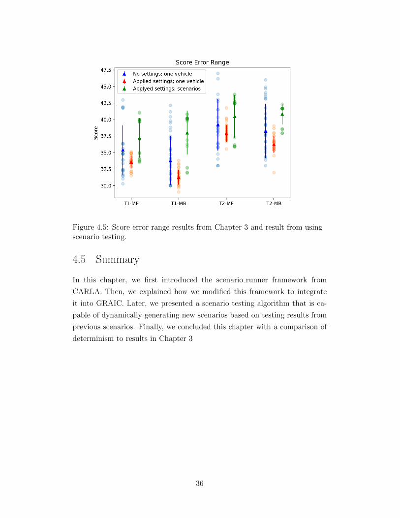
Figure 4.5: Score error range results from Chapter 3 and result from usingscenario testing.
4.5 Summary
In this chapter, we first introduced the scenario runner framework from
CARLA. Then, we explained how we modified this framework to integrate
it into GRAIC. Later, we presented a scenario testing algorithm that is ca-
pable of dynamically generating new scenarios based on testing results from
previous scenarios. Finally, we concluded this chapter with a comparison of
determinism to results in Chapter 3
36
CHAPTER 5
CONCLUSION AND FUTURE WORK
In this thesis, we presented three main contributions that may assist in the
continuous integration and testing of AVs. First, we present GRAIC which
is an intelligent racing competition framework for evaluating decision and
control logic of autonomous driving systems. To automate the evaluation
of the submitted controller code, we implemented a testing pipeline, named
AutOps, based on software engineering tools like Jenkins and Docker. We also
provide analysis of the determinism and performance of our testing pipeline.
In order to complicate the GRAIC competition with non-trivial scenarios, we
developed a scenario generation framework based on CARLA scenario runner
that can dynamically generate scenarios based on the results of ego-vehicle
passing previous scenarios.
For future work, we can also expect breakthroughs in three aspects:
First, GRAIC can be further developed to allow multiple vehicles racing
together while still preserving the determinism. It is also desired to incorpo-
rate more race tracks. Then, more interesting scenarios can be created and
included in the scenario generation framework.
Second, in terms of AutOps, a reasonable and crucial enhancement is to
develop a load balancer to dynamically create instances of GRAIC docker ac-
cording to the need. Currently, the number of GRAIC instances is fixed, lim-
ited by the computing performance of the server on which AutOps is deployed.
This could be done by integrating a Kubernetes Engine with Jenkins [53].
In this way, based on the amount of submitted controllers, Kubernetes will
dynamically configure GRAIC instance to satisfy the needs. Moreover, we
can extend the capability of AutOps by adding more tools to perform other
types of tasks. For example, we can add DryVR to verify the safety of the
vehicle controller during the testing [34].
Last but not least, for the scenario generation framework, deep learning
methods can be exploited to increase the effectiveness. Currently, the gen-
37

eration of composite scenarios is more or less based on a greedy heuristic.
A possible extension is to use LSTM-RNN to keep track of the history of
the ego-vehicle behaviors and produce composite scenarios. The advantage
of LSTM is its capability of memorizing sequential information in long-term
and short-term memory and learning from these histories.
38

REFERENCES
[1] D. Wakabayashi, “Self-driving Uber car kills pedestrian in Ari-zona, where robots roam,” https://www.nytimes.com/2018/03/19/technology/uber-driverless-fatality.html, 2018.
[2] J. Bursztynsky, “Uber sells its self-driving unit to Aurora,” https://www.cnbc.com/2020/12/07/uber-sells-atg-self-driving-unit-to-aurora-.html, 2020.
[3] S. Shalev-Shwartz, S. Shammah, and A. Shashua, “On a formal modelof safe and scalable self-driving cars,” CoRR, vol. abs/1708.06374,2017. [Online]. Available: http://arxiv.org/abs/1708.06374
[4] DMV of State of California, “2019 autonomous mileage re-ports (csv),” https://www.dmv.ca.gov/portal/uploads/2020/06/2019AutonomousMileageReports.csv, 2019.
[5] DMV of State of California, “2020 autonomous mileagereports (csv),” https://www.dmv.ca.gov/portal/file/2020-autonomous-mileage-reports-csv/, 2020.
[6] J. Deng, W. Dong, R. Socher, L.-J. Li, K. Li, and L. Fei-Fei, “Imagenet:A large-scale hierarchical image database,” in 2009 IEEE conference oncomputer vision and pattern recognition. IEEE, 2009, pp. 248–255.
[7] M. Jiang, Z. Liu, K. Miller, D. Sun, A. Datta, Y. Jia, S. Mitra, andN. Ozay, “GRAIC: A simulator framework for autonomous racing,”https://popgri.github.io/Race/, 2021.
[8] “CARLA ScenarioRunner,” https://carla-scenariorunner.readthedocs.io/en/latest, 2018.
[9] A. Dosovitskiy, G. Ros, F. Codevilla, A. Lopez, and V. Koltun,“CARLA: An open urban driving simulator,” in Proceedings of the 1stAnnual Conference on Robot Learning, 2017, pp. 1–16.
[10] N. Koenig and A. Howard, “Design and use paradigms for gazebo, anopen-source multi-robot simulator,” in IEEE/RSJ International Con-ference on Intelligent Robots and Systems, Sendai, Japan, Sep 2004, pp.2149–2154.
39
[11] G. Rong, B. H. Shin, H. Tabatabaee, Q. Lu, S. Lemke, M. Mozeiko,E. Boise, G. Uhm, M. Gerow, S. Mehta, E. Agafonov, T. H. Kim,E. Sterner, K. Ushiroda, M. Reyes, D. Zelenkovsky, and S. Kim,“LGSVL simulator: A high fidelity simulator for autonomous driving,”IEEE 23rd International Conference on Intelligent Transportation Sys-tems (ITSC), 2020.
[12] Rockstar Games, “Grand Theft Auto V.” [Online]. Available:https://www.rockstargames.com/games/V
[13] M. DeBord, “A Waymo engineer told us why a virtual-world simulation is crucial to the future of self-driving cars,”https://www.businessinsider.com/waymo-engineer-explains-why-testing-self-driving-cars-virtually-is-critical-2018-8, 2018.
[14] “2021 ICRA Full-Day Workshop,” https://linklab-uva.github.io/icra-autonomous-racing/, 2021.
[15] B. Wymann, E. Espie, C. Guionneau, C. Dimitrakakis, R. Coulom,and A. Sumner, “TORCS, The Open Racing Car Simulator,”http://www.torcs.org, 2014.
[16] “PLIB,” http://plib.sourceforge.net/, 2006.
[17] Epic Games, “Unreal engine.” [Online]. Available: https://www.unrealengine.com
[18] Fastlap Simulation and Engineering, “Fastlap,”http://fastlap.tech/index.html, 2014.
[19] “Intel Lab,” https://www.intel.com/content/www/us/en/research/overview.html, 2021.
[20] “Computer Vision Center,” http://www.cvc.uab.es/, 2021.
[21] “Toyota Research Institute,” https://www.tri.global/, 2021.
[22] “FutureWei,” https://www.futurewei.com/, 2021.
[23] CARLA Team, Intel ISL, Open Source Vision Foundation and Al-phaDrive, “Carla autonomous driving leaderboard,” 2020.
[24] V. S. Babu and M. Behl, “F1tenth.dev-An open-source ROS basedF1/10 autonomous racing simulator,” in 2020 IEEE 16th InternationalConference on Automation Science and Engineering (CASE). IEEE,2020, pp. 1614–1620.
[25] “ROS Build Farm,” http://wiki.ros.org/build.ros.org, 2021.
40
[26] F. Pinter and A. Engelstein, “Automating simulation for safer self-driving,” AImotive Insights, 2019.
[27] K. Gajananan, A. Nantes, M. Miska, A. Nakasone, and H. Prendinger,“An experimental space for conducting controlled driving behavior stud-ies based on a multiuser networked 3d virtual environment and the sce-nario markup language,” IEEE Transactions on Human-Machine Sys-tems, vol. 43, no. 4, pp. 345–358, 2013.
[28] M. Wen, J. Park, and K. Cho, “A scenario generation pipeline for au-tonomous vehicle simulators,” Human-centric Computing and Informa-tion Sciences, vol. 10, pp. 1–15, 2020.
[29] S. T. Chrysler, O. Ahmad, and C. W. Schwarz, “Creating pedestriancrash scenarios in a driving simulator environment,” Traffic InjuryPrevention, vol. 16, no. sup1, pp. S12–S17, 2015, pMID: 26027964.[Online]. Available: https://doi.org/10.1080/15389588.2015.1015001
[30] S. Feng, X. Yan, H. Sun, Y. Feng, and H. X. Liu, “Intelligent driving in-telligence test for autonomous vehicles with naturalistic and adversarialenvironment,” Nature Communications, vol. 12, no. 1, pp. 1–14, 2021.
[31] R. van der Made, M. Tideman, U. Lages, R. Katz, and M. Spencer, “Au-tomated generation of virtual driving scenarios from test drive data,”in 24th International Technical Conference on the Enhanced Safety ofVehicles (ESV) National Highway Traffic Safety Administration, no. 15-0268, 2015.
[32] J. Park, M. Wen, Y. Sung, and K. Cho, “Multiple event-based simulationscenario generation approach for autonomous vehicle smart sensors anddevices,” Sensors, vol. 19, no. 20, p. 4456, 2019.
[33] S. Mitra, Verifying Cyber-Physical Systems: A Path to Safe Autonomy.MIT Press, 2021.
[34] C. Fan, B. Qi, S. Mitra, and M. Viswanathan, “DryVR: Data-DrivenVerification and Compositional Reasoning for Automotive Systems,”in Computer Aided Verification - 29th International Conference, CAV2017, Heidelberg, Germany, July 24-28, 2017, Proceedings, Part I, 2017,pp. 441–461.
[35] B. Qi, C. Fan, M. Jiang, and S. Mitra, “DryVR 2.0: A tool for veri-fication and controller synthesis of black-box cyber-physical systems,”in Proceedings of the 21st International Conference on Hybrid Systems:Computation and Control (part of CPS Week), HSCC 2018, Porto, Por-tugal, April 11-13, 2018, M. Prandini and J. V. Deshmukh, Eds. ACM,2018, pp. 269–270.
41
[36] A. Donze, “Breach, a toolbox for verification and parameter synthe-sis of hybrid systems,” in International Conference on Computer AidedVerification. Springer, 2010, pp. 167–170.
[37] C. Fan and S. Mitra, “Bounded verification with on-the-fly discrepancycomputation,” in 13th Intl. Symposium on Automated Technology forVerification and Analysis (ATVA 2015), Sanghai, China., ser. LNCS,vol. 9364, 2015, pp. 446–463.
[38] P. S. Duggirala, S. Mitra, and M. Viswanathan, “Verification of anno-tated models from executions,” in Proceedings of International Confer-ence on Embedded Software (EMSOFT 2013), ACM SIGBED. Mon-treal, QC, Canada: IEEE, September 2013, pp. 1–10.
[39] C. Fan, B. Qi, and S. Mitra, “Data-driven formal reasoning and their ap-plications in safety analysis of vehicle autonomy features,” IEEE DesignTest, vol. 35, no. 3, pp. 31–38, Jan. 2018.
[40] P. S. Duggirala, L. Wang, S. Mitra, C. Munoz, and M. Viswanathan,“Temporal precedence checking for switched models and its applicationto a parallel landing protocol,” in International Conference onFormal Methods (FM 2014), Singapore, 2014. [Online]. Available:http://link.springer.com/chapter/10.1007%2F978-3-319-06410-9 16
[41] P. S. Duggirala, C. Fan, S. Mitra, and M. Viswanathan, “Meeting apowertrain verification challenge,” in In the Proceedings of InternationalConference on Computer Aided Verification (CAV 2015), ser. LNCS, vol.9206. San Francisco: Springer, 2015, pp. 536–543.
[42] D. J. Fremont, T. Dreossi, S. Ghosh, X. Yue, A. L. Sangiovanni-Vincentelli, and S. A. Seshia, “Scenic: A language for scenario specifi-cation and scene generation,” Proceedings of the 40th ACM SIGPLANConference on Programming Language Design and Implementation, Jun2019. [Online]. Available: http://dx.doi.org/10.1145/3314221.3314633
[43] H. Sibai, Y. Li, and S. Mitra, “Scenechecker: Boosting scenario verifi-cation using symmetry abstractions,” arXiv:2011.10713v2, 2021.
[44] H. Sibai, N. Mokhlesi, C. Fan, and S. Mitra, “Multi-agentsafety verification using symmetry transformations,” in Tools andAlgorithms for the Construction and Analysis of Systems - 26thInternational Conference, TACAS 2020, Held as Part of theEuropean Joint Conferences on Theory and Practice of Software,ETAPS 2020, Dublin, Ireland, April 25-30, 2020, Proceedings,Part I, ser. Lecture Notes in Computer Science, A. Biere andD. Parker, Eds., vol. 12078. Springer, 2020. [Online]. Available:https://doi.org/10.1007/978-3-030-45190-5 10 pp. 173–190.
42

[45] H. Sibai, N. Mokhlesi, and S. Mitra, “Using symmetry transformationsin equivariant dynamical systems for their safety verification,” inAutomated Technology for Verification and Analysis - 17th InternationalSymposium, ATVA 2019, Taipei, Taiwan, October 28-31, 2019,Proceedings, ser. Lecture Notes in Computer Science, Y. Chen,C. Cheng, and J. Esparza, Eds., vol. 11781. Springer, 2019. [Online].Available: https://doi.org/10.1007/978-3-030-31784-3 6 pp. 98–114.
[46] A. Corso, P. Du, K. Driggs-Campbell, and M. J. Kochenderfer, “Adap-tive stress testing with reward augmentation for autonomous vehicle val-idation,” IEEE Intelligent Transportation Systems Conference (ITSC),pp. 163–168, 2019.
[47] Stanford Artificial Intelligence Laboratory et al., “Robotic operatingsystem.” [Online]. Available: https://www.ros.org
[48] K. Miller, C. Fan, and S. Mitra, “Planning in dynamic and partiallyunknown environments,” in In Proceedings of 7th IFAC Conference onAnalysis and Design of Hybrid Systems (ADHS’21), July 2021.
[49] CloudBees, “Jenkins,” https://www.jenkins.io/, 2011.
[50] D. Merkel, “Docker: Lightweight Linux containers for consistent devel-opment and deployment,” Linux Journal, vol. 2014, no. 239, p. 2, 2014.
[51] M. Posa, C. Cantu, and R. Tedrake, “A direct method for trajectoryoptimization of rigid bodies through contact,” The International Journalof Robotics Research, vol. 33, no. 1, pp. 69–81, 2014.
[52] D. Stonier, N. Usmani, and M. Staniaszek, “Py Trees,” https://py-trees.readthedocs.io/en/devel/, 2020.
[53] “Kubernetes,” https://kubernetes.io/docs/home/, 2021, [Online; ac-cessed 04-Apr-2021].
43