22-1796-14 product data - trane€¦ · ©2013 trane pub. no. 22-1796-14 product data 4tcy4024...
TRANSCRIPT

© 2013 Trane Pub. No. 22-1796-14
Product Data4TCY4024 through 4TCY4060Single Packaged Convertible Cooling14 SEER 2 - 5 TonR-410A
22-1796-14

2
It's Hard to Stop a Trane.Single Packaged Cooling SystemTrane offers a complete family of cooling systems, designed to give you the unbeat-able combination of energy efficiency and lower operating costs.
Introducing the new TRANE Single Packaged Cooling System.
Single Packaged Cooling Systems are easy and versatile to install. Because cooling and air handling functions are all contained in a single cabinet, a Trane packaged air condi-tioner is easy to install and service. It can be flush mounted beside your home at ground level or placed on the roof for horizontal or downflow installation. When connected to an optional Trane thermostat control, and air distribution ducts, you have a highly ef-ficient, total home comfort system.
Single Packaged Cooling Systems provide
better performance. Our single packaged air conditioners offer cooling efficiencies that are unmatched in the industry and provide you with a product far superior in performance than the competition.

3
Contents
Optional Equipment Listing 4
General Data 5
Heater Data 8
SPEK Data 9
Performance Data
Indoor Fan 12
Typical Wiring 15
Optional Equipment 18
Dimensional Data 23
Mechanical Specifications 29

4
Optional Equipment
OPTIONAL EQUIPMENT FOR PACKAGED UNITS (check mark [3] indicates accessories included)
Hinged Filter Access Door (4TCY4024-036) ...................................................................... BAYACCDOR1A[ ]Hinged Filter Access Door (4TCY4042-060) ...................................................................... BAYACCDOR2A[ ]Roof Curb Full Perimeter (4TCY4024-36) 3 ......................................................................BAYCURB050A[ ]Roof Curb Full Perimeter (4TCY4042-060) 3 ....................................................................BAYCURB051A[ ]Roof Curb Utility Extension Kit (BAYCURB050A)....................................................................BAYUTIL101B[ ]Roof Curb Utility Extension Kit (BAYCURB051A)....................................................................BAYUTIL102B[ ]0-25% Manual Fresh Air Damper (4TCY4024-36) 1. ..........................................................BAYOSAH001A[ ]0-25% Manual Fresh Air Damper (4TCY4042-060) 1. ........................................................BAYOSAH002A[ ]Motorized Fresh Air Damper (4TCY4024-36) 1. ............................................................... BAYDMPR101A[ ]Motorized Fresh Air Damper (4TCY4042-060) 1. .............................................................. BAYDMPR102A[ ]16" Round Duct Adapter (2 per box) (4TCY4024-36) 6 .................................................... BAYSQRD001A[ ]18" Round Duct Adapter (2 per box) (4TCY4024-060) 6 .................................................. BAYSQRD002A[ ]0-100% Mod Economizer w/Baro. Relief (4TCY4024-36) 24 .......................................... BAYECON101B[ ]0-100% Mod. Economizer w/Baro. Relief (4TCY4042-060A) 124. .................................. BAYECON102B[ ]0-100% Horizontal Economizer (4TCY4024-36) 12 . ....................................................... BAYECON200A[ ]0-100% Horizontal Economizer (4TCY4042-060) 12 . ..................................................... BAYECON201A[ ]Enthalpy Control for Economizer (solid state). ......................................................................BAYENTH001A[ ]Remote Potentiometer (All-BAYECON***A) .............................................................................BAYSTAT023[ ]1"-2" Filter Frame (4TCY4024-36) (20 x 25 filter not included) 1. ............ BAYFLTR101B[ ]1"-2" Filter Frame (4TCY4042-060) (20 x 20 & 20 x18 filter not included) 1. ...... BAYFLTR201B[ ]Head Pressure Control (Low Ambient Cool) (208/240v) Kit 5. ...........................................BAYLOAM105A[ ] Quick Start Kit (4TCY4-‡1) ................................................................................................... BAYKSKT300A[ ]Crankcase Heater Recip (4TCY4024‡1 (230v) 5................................................................BAYCCHT101A[ ]Crankcase Heater Scroll (4TCY4036-060‡1/3)(230v) 5. ....................................................BAYCCHT102A[ ]Adapter Curb 4TCY4024-36 to BAYCURB030,38 ............................................................... BAYADAP050A[ ] Adapter Curb 4TCY4024-36 to BAYCURB033 .................................................................... BAYADAP051A[ ] Adapter Curb 4TCY4042-060 to BAYCURB030,38 ............................................................. BAYADAP052A[ ] Adapter Curb 4TCY4042-060 to BAYCURB033 .................................................................. BAYADAP053A[ ] Adapter Curb 4TCY4042-060 to BAYCURB034 .................................................................. BAYADAP054A[ ]12" Duct Shroud Covers Horizontal 4TCY4024-0607. ........................................................BAYCOVR112A[ ]18" Duct Shroud Covers Horizontal 4TCY4024-060 7. .......................................................BAYCOVR118A[ ] Extreme Condition Mounting Kit - All BAYCURB & BAYADAP .............................................BAYEXMK001A[ ]Extreme Condition Mounting Kit - All BAYUTIL ....................................................................BAYEXMK002B[ ] Extreme Condition Mounting Kit - All Slab Mounts ...............................................................BAYEXMK003A[ ]Lifting Lug Kit ...........................................................................................................................BAYLlFT002B[ ]SUPPLEMENTARY HEATERS (1 PHASE)3.76/5.0 KW Heater (208/240V 1PH) (4TCY4024-060‡1) ................................................... BAYHTRV105E[ ] 3.76/5.0 KW Heater (208/240V 1PH) (4TCY4024-060‡1) ................................................... BAYHTRV108E[ ]7.50/10.0 KW Heater (208/240V 1PH) (4TCY4024-060‡1) ................................................. BAYHTRV110E[ ]11.27/15.00 KW Heater (208/240V 1PH) (4TCY4030-060‡1) ............................................. BAYHTRV115E[ ]15.0/20.0 KW Heater (208/240V 1PH) (*4TCY4042-060‡1) ................................................ BAYHTRV120E[ ]18.78/25.0 KW Heater (208/240V 1PH) (4TCY4042-060‡1).... ............................................ BAYHTRV125E[ ]SUPPLEMENTARY HEATERS (3 PHASE)3.76/5.0 KW Heater (208/240V 3PH) (4TCY4036-060‡3) ................................................... BAYHTRV305E[ ] 3.76/5.0 KW Heater (208/240V 3PH) (4TCY4036-060‡3) ................................................... BAYHTRV308E[ ] 7.50/10.0 KW Heater (208/240V 3PH) (4TCY4024-48‡3) ................................................... BAYHTRV310E[ ]11.27/15.00 KW Heater (208/240V 3PH) (4TCY4036-060‡3) ............................................. BAYHTRV315E[ ]15.00/20.0 KW Heater (208/240V 3PH) (4TCY4048-060‡3) ............................................... BAYHTRV320E[ ]18.78/25.0 KW Heater (208/240V 3PH) (4TCY4048-060‡3).... ............................................ BAYHTRV325E[ ]Single Power Entry Kit 8 . .................................................................................................... BAYSPEK060F[ ]Single Power Entry Kit 8 . .................................................................................................... BAYSPEK061E[ ]Single Power Entry Kit 8 . .................................................................................................... BAYSPEK062F[ ]Single Power Entry Kit 8 . .................................................................................................... BAYSPEK063F[ ]Single Power Entry Kit 8 . .................................................................................................... BAYSPEK064E[ ]Single Power Entry Kit 8 . .................................................................................................... BAYSPEK065E[ ]
NOTES: 1 Must use internal filter frame when economizer or fresh air kit is used. 2 Dry bulb control standard with economizer. 3 Ships knocked down. 4 Downflow only. 5 Low Ambient cooling requires crankcase heater (BAYCCHT----B). 6 It is the responsibility of the installing dealer to properly size the ductwork for each specific application. 7 BAYCOVR112,118A will not cover BAYSQRD002A applications. 8 See table on page 8 for matching kit with units and heaters. ‡ = A or B

5
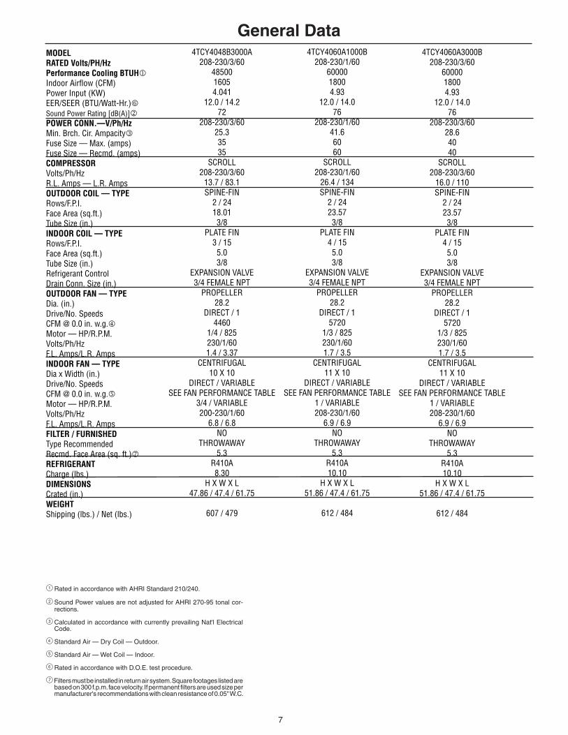
MODELRATED Volts/PH/HzPerformance Cooling BTUHIndoor Airflow (CFM)Power Input (KW)EER/SEER (BTU/Watt-Hr.)Sound Power Rating [dB(A)]POWER CONN.—V/Ph/HzMin. Brch. Cir. AmpacityFuse Size — Max. (amps)Fuse Size — Recmd. (amps)COMPRESSORVolts/Ph/HzR.L. Amps — L.R. AmpsOUTDOOR COIL — TYPERows/F.P.I.Face Area (sq.ft.)Tube Size (in.)INDOOR COIL — TYPERows/F.P.I.Face Area (sq.ft.)Tube Size (in.)Refrigerant ControlDrain Conn. Size (in.)OUTDOOR FAN — TYPEDia. (in.)Drive/No. SpeedsCFM @ 0.0 in. w.g.Motor — HP/R.P.M.Volts/Ph/HzF.L. Amps/L.R. AmpsINDOOR FAN — TYPEDia x Width (in.)Drive/No. SpeedsCFM @ 0.0 in. w.g.Motor — HP/R.P.M.Volts/Ph/HzF.L. Amps/L.R. AmpsFILTER / FURNISHEDType RecommendedRecmd. Face Area (sq. ft.)REFRIGERANTCharge (lbs.)DIMENSIONSCrated (in.)WEIGHTShipping (lbs.) / Net (lbs.)
1 Rated in accordance with AHRI Standard 210/240.
2 Sound Power values are not adjusted for ARI 270-95 tonal corrections.
3 Calculated in accordance with currently prevailing Nat'l Electrical Code.
4 Standard Air — Dry Coil — Outdoor.
5 Standard Air — Wet Coil — Indoor.
6 Rated in accordance with D.O.E. test procedure.
7 Filters must be installed in return air system. Square footages listed are based on 300 f.p.m. face velocity. If permanent filters are used size per manufacturer's recommendations with clean resistance of 0.05" W.C.
General Data4TCY4024A1000B
208-230/1/60234007801.99
12 / 14.068
208-230/1/6016.52525
RECIPROCATING200-230/1/60
8.3 / 57.8SPINE-FIN
2 / 2413.323/8
PLATE FIN3 / 153.543/8
EXPANSION VALVE3/4 FEMALE NPT
PROPELLER23.4
DIRECT / 12560
1/12 / 810230/1/60
0.54 / 0.95CENTRIFUGAL
10 X 10DIRECT / VARIABLE
SEE FAN PERFORMANCE TABLE1/2 / VARIABLE200-230/1/60
4.3 / 4.3NO
THROWAWAY4.0
R410A6.0
H X W X L45.86 / 44.5 / 52.03
444 / 348
4TCY4030A1000B208-230/1/60
300009002.5
12.0 / 14.071
208-230/1/6019.13030
RECIPROCATING208-230/1/60
11.1 / 63SPINE-FIN
2 / 2413.323/8
PLATE FIN3 / 153.543/8
EXPANSION VALVE3/4 FEMALE NPT
PROPELLER23.4
DIRECT / 12550
1/6 / 830208-230/1/60
0.9 / 1.7CENTRIFUGAL
10 X 10DIRECT / VARIABLE
SEE FAN PERFORMANCE TABLE1/2 / VARIABLE208-230/1/60
4.3 / 4.3NO
THROWAWAY4.0
R410A6.30
H X W X L45.86 / 44.5 / 52.03
444 / 348
4TCY4036B1000B208-230/1/60
3800011953.17
12.0 / 14.269
208-230/1/6026.34040
SCROLL208-230/1/60
16.7 / 69SPINE-FIN
2 / 2415.493/8
PLATE FIN4 / 153.543/8
EXPANSION VALVE3/4 FEMALE NPT
PROPELLER23.4
DIRECT / 13300
1/5 / 830230/1/601.1 / 1.9
CENTRIFUGAL10 X 10
DIRECT / VARIABLESEE FAN PERFORMANCE TABLE
1/2 / VARIABLE200-230/1/60
4.3 / 4.3NO
THROWAWAY4
R410A7.80
H X W X L47.86 / 44.5 / 52.03
450 / 354

6
General Data
1 Rated in accordance with AHRI Standard 210/240.
2 Sound Power values are not adjusted for AHRI 270-95 tonal cor-rections.
3 Calculated in accordance with currently prevailing Nat'l Electrical Code.
4 Standard Air — Dry Coil — Outdoor.
5 Standard Air — Wet Coil — Indoor.
6 Rated in accordance with D.O.E. test procedure.
7 Filters must be installed in return air system. Square footages listed are based on 300 f.p.m. face velocity. If permanent filters are used size per manufacturer's recommendations with clean resistance of 0.05" W.C.
MODELRATED Volts/PH/HzPerformance Cooling BTUHIndoor Airflow (CFM)Power Input (KW)EER/SEER (BTU/Watt-Hr.)Sound Power Rating [dB(A)]POWER CONN.—V/Ph/HzMin. Brch. Cir. AmpacityFuse Size — Max. (amps)Fuse Size — Recmd. (amps)COMPRESSORVolts/Ph/HzR.L. Amps — L.R. AmpsOUTDOOR COIL — TYPERows/F.P.I.Face Area (sq.ft.)Tube Size (in.)INDOOR COIL — TYPERows/F.P.I.Face Area (sq.ft.)Tube Size (in.)Refrigerant ControlDrain Conn. Size (in.)OUTDOOR FAN — TYPEDia. (in.)Drive/No. SpeedsCFM @ 0.0 in. w.g.Motor — HP/R.P.M.Volts/Ph/HzF.L. Amps/L.R. AmpsINDOOR FAN — TYPEDia x Width (in.)Drive/No. SpeedsCFM @ 0.0 in. w.g.Motor — HP/R.P.M.Volts/Ph/HzF.L. Amps/L.R. AmpsFILTER / FURNISHEDType RecommendedRecmd. Face Area (sq. ft.)REFRIGERANTCharge (lbs.)DIMENSIONSCrated (in.)WEIGHTShipping (lbs.) / Net (lbs.)
4TCY4036B3000A208-230/3/60
3700011953.17
12.0 / 14.269
208-230/3/6018.42525
SCROLL208-230/3/60
10.4 / 73SPINE-FIN
2 / 2415.493/8
PLATE FIN4 / 153.543/8
EXPANSION VALVE3/4 FEMALE NPT
PROPELLER23.4
DIRECT / 13260
1/5 / 830230/1/601.1 / 1.9
CENTRIFUGAL10 X 10
DIRECT / VARIABLESEE FAN PERFORMANCE TABLE
1/2 / VARIABLE200-230/1/60
4.3 / 4.3NO
THROWAWAY4
R410A7.80
H X W X L47.86 / 44.5 / 52.03
450 / 354
4TCY4042B1000B208-230/1/60
4200014203.5
12.0 / 14.2574
208-230/1/6030.74545
SCROLL208-230/1/60
17.9 / 112SPINE-FIN
2 / 2418.013/8
PLATE FIN3 / 15
53/8
EXPANSION VALVE3/4 FEMALE NPT
PROPELLER28.2
DIRECT / 14460
1/4 / 825208-230/1/60
1.4 / 3.4CENTRIFUGAL
11 X 10DIRECT / VARIABLE
SEE FAN PERFORMANCE TABLE3/4 / VARIABLE208-230/1/60
6.8 / 6.8NO
THROWAWAY5.3
R410A7.00
H X W X L47.86 / 47.4 / 61.75
607 / 479
4TCY4048B1000B208-230/1/60
4850016054.041
12 / 14.272
208-230/1/6035.55050
SCROLL208-230/1/60
21.8 / 117SPINE-FIN
2 / 2418.013/8
PLATE FIN3 / 15
5.03/8
EXPANSION VALVE3/4 FEMALE NPT
PROPELLER28.2
DIRECT / 14460
1/4 / 825230/1/601.4 / 3.37
CENTRIFUGAL10 X 10
DIRECT / VARIABLESEE FAN PERFORMANCE TABLE
3/4 / VARIABLE200-230/1/60
6.8 / 6.8NO
THROWAWAY5.3
R410A8.30
H X W X L47.86 / 47.4 / 61.75
623 / 495
7
General Data
1 Rated in accordance with AHRI Standard 210/240.
2 Sound Power values are not adjusted for AHRI 270-95 tonal cor-rections.
3 Calculated in accordance with currently prevailing Nat'l Electrical Code.
4 Standard Air — Dry Coil — Outdoor.
5 Standard Air — Wet Coil — Indoor.
6 Rated in accordance with D.O.E. test procedure.
7 Filters must be installed in return air system. Square footages listed are based on 300 f.p.m. face velocity. If permanent filters are used size per manufacturer's recommendations with clean resistance of 0.05" W.C.
MODELRATED Volts/PH/HzPerformance Cooling BTUHIndoor Airflow (CFM)Power Input (KW)EER/SEER (BTU/Watt-Hr.)Sound Power Rating [dB(A)]POWER CONN.—V/Ph/HzMin. Brch. Cir. AmpacityFuse Size — Max. (amps)Fuse Size — Recmd. (amps)COMPRESSORVolts/Ph/HzR.L. Amps — L.R. AmpsOUTDOOR COIL — TYPERows/F.P.I.Face Area (sq.ft.)Tube Size (in.)INDOOR COIL — TYPERows/F.P.I.Face Area (sq.ft.)Tube Size (in.)Refrigerant ControlDrain Conn. Size (in.)OUTDOOR FAN — TYPEDia. (in.)Drive/No. SpeedsCFM @ 0.0 in. w.g.Motor — HP/R.P.M.Volts/Ph/HzF.L. Amps/L.R. AmpsINDOOR FAN — TYPEDia x Width (in.)Drive/No. SpeedsCFM @ 0.0 in. w.g.Motor — HP/R.P.M.Volts/Ph/HzF.L. Amps/L.R. AmpsFILTER / FURNISHEDType RecommendedRecmd. Face Area (sq. ft.)REFRIGERANTCharge (lbs.)DIMENSIONSCrated (in.)WEIGHTShipping (lbs.) / Net (lbs.)
4TCY4048B3000A208-230/3/60
4850016054.041
12.0 / 14.272
208-230/3/6025.33535
SCROLL208-230/3/60
13.7 / 83.1SPINE-FIN
2 / 2418.013/8
PLATE FIN3 / 15
5.03/8
EXPANSION VALVE3/4 FEMALE NPT
PROPELLER28.2
DIRECT / 14460
1/4 / 825230/1/601.4 / 3.37
CENTRIFUGAL10 X 10
DIRECT / VARIABLESEE FAN PERFORMANCE TABLE
3/4 / VARIABLE200-230/1/60
6.8 / 6.8NO
THROWAWAY5.3
R410A8.30
H X W X L47.86 / 47.4 / 61.75
607 / 479
4TCY4060A1000B208-230/1/60
6000018004.93
12.0 / 14.076
208-230/1/6041.66060
SCROLL208-230/1/60
26.4 / 134SPINE-FIN
2 / 2423.573/8
PLATE FIN4 / 15
5.03/8
EXPANSION VALVE3/4 FEMALE NPT
PROPELLER28.2
DIRECT / 15720
1/3 / 825230/1/601.7 / 3.5
CENTRIFUGAL11 X 10
DIRECT / VARIABLESEE FAN PERFORMANCE TABLE
1 / VARIABLE208-230/1/60
6.9 / 6.9NO
THROWAWAY5.3
R410A10.10
H X W X L51.86 / 47.4 / 61.75
612 / 484
4TCY4060A3000B208-230/3/60
6000018004.93
12.0 / 14.076
208-230/3/6028.64040
SCROLL208-230/3/60
16.0 / 110SPINE-FIN
2 / 2423.573/8
PLATE FIN4 / 15
5.03/8
EXPANSION VALVE3/4 FEMALE NPT
PROPELLER28.2
DIRECT / 15720
1/3 / 825230/1/601.7 / 3.5
CENTRIFUGAL11 X 10
DIRECT / VARIABLESEE FAN PERFORMANCE TABLE
1 / VARIABLE208-230/1/60
6.9 / 6.9NO
THROWAWAY5.3
R410A10.10
H X W X L51.86 / 47.4 / 61.75
612 / 484

8
Heater Data4TCY4024 to 4TCY4060 Heater Data
General Table Notes:
Any power supply and circuits must be wired and protected in accordance with local electrical codes. 2 The MCA values listed are for electric heater only. Field wire must be rated at least 75°C 4 The HACR circuit breaker is for U.S.A. installations only. 5 For Canada installation reference only. # Heater uses fuses.
Unit Model Notes:
^ = 2 or 4
* = C or X
‡ = A or B
KW BTUH 1 2
^W/TC*3018-060‡1^W/TCY4024-060‡1^WCZ6036-060‡1
^W/TC*3018-060‡1^W/TCY4024-060‡1^WCZ6036-060‡1
BAYHTRV108E 208/240 1 29/33 6.0/8.0 20500/27300 1 6.0/8.0 36/41 40/45 40/45
^W/TC*3024-060‡1^W/TCY4024-060‡1^WCZ6036-060‡1
^W/TC*3030-060‡1^W/TCY4030-060‡1^WCZ6036-060‡1
^W/TC*3042-060‡1^W/TCY4042-060‡1^WCZ6048-060‡1
4WC*3042‡1^W/TC*3060‡1
^W/TCY4042-060‡1^WCZ6048-060‡1
^W/TC*3036-060‡3^W/TCY4036-060‡3^WCZ6036-060‡3
^W/TC*3036-060‡3^W/TCY4036-060‡3^WCZ6036-060‡3
BAYHTRV308E 208/240 3 17/19 6.0/8.0 20500/27300 1 6.0/8.0 21/24 25/25 25/25
^W/TC*3036-060‡3^W/TCY4036-060‡3^WCZ6036-060‡3
^W/TC*3036-060‡3^W/TCY4036-060‡3^WCZ6036-060‡3
^W/TC*3048-060‡3^W/TCY4048-060‡3^WCZ6048-060‡3
^W/TC*3036-060‡4^WCZ6036-060‡4
BAYHTRV408E 480 3 10 8.0 27300 1 8.0 13 15 15
^WCZ6036-060‡4
^W/TC*3036-060‡4^WCZ6036-060‡4
^W/TC*3048-060‡4^WCZ6048-060‡4
^W/TC*3060‡4^WCZ6048-060‡4
7.5/10.0
40/45 40/45
208/240 3 42/48 15.0/20.0 51200/68300 2 7.5/10.0
45/60
208/240 1 54/63 11.27/15.0 38500/51200 2 7.5/10.0
1 36/42 7.5/10.0 25600/34100
^W/TC*3036-060‡4
BAYHTRV115E#
BAYHTRV110E
BAYHTRV120E#
BAYHTRV305E
BAYHTRV310E
BAYHTRV315E
BAYHTRV320E
BAYHTRV325E#
MAX FUSE OR HACR CKT
BKR SIZE (4)
CANADA ONLY MAX. CKT BKR
SIZE (5)MCA AMPS
NO. OF STAGES
KW/STAGEHEATER CAPACITY
PHASEELECTRIC
HEATER MODELRATED
VOLTAGEUNIT MODEL
3
3
3
BAYHTRV105E
480
208/240 3
208/240
480 24 20.0
90/104 18.78/25.0
3
480
31/36 11.27/15.0
68300
8530025.030
5120015.018
12 10.0 34100
2
2
2
1
10.0
38
30
235.010.0
10.0
10.0 040.51
25
30
40
25
30
15
52/60 60/60
65/75
8
15
08/072
15
5.0
1 10.0
11.26/15.0 7.5/10.0
2 7.5/10.0 3.76/5.0
7.5/10.0
39/45
26/30 30/30 30/30
10/12 3.76/5.0 12800/17100 1 3.76/5.0
21/24 7.5/10.0 25600/34100 1
90/110
3.76/5.0 68/78
64100/85300 2 11.26/15.0 7.5/10.0
70/80
113/130 125/150
7.5/10.0 90/104 90/110
3.76/5.0 12800/17100 1 3.76/5.0
1 7.5/10.0
25/3023/26
45/52 45/60
25/30
70/80
208/240 1 72/83 15.0/20.0 51200/68300 2 7.5/10.0
BAYHTRV420E
BAYHTRV425E
60/60
70/80
15 15BAYHTRV405E
BAYHTRV410E
480
480
208/240 1 18/21
BAYHTRV415E
208/240
208/240 3
208/240 3
3
^W/TC*3060‡3^W/TCY4048-060‡3^WCZ6048-060‡3
^W/TC*3036-060‡4^WCZ6036-060‡4
BAYHTRV125E#
38500/51200
171006 5.0
52/60 18.78/25.0 64100/85300
125/150
208/240 3 13/15 15/15 15/15
1

9
Single Power Entry Kit Data
Notes:
* = C or X
‡ = A or B

10
Single Power Entry Kit Data
Notes:
* = C or X
‡ = A or B

11
Single Power Entry Kit Data
Notes:
* = C or X
‡ = A or B

12
Indoor Blower Performance
Indoor Fan Performance (230v) 4TCY4030 (230vperformance)
Down Airflow
Horizontal AirflowIndoor Fan Performance (230v) 4TCY4024 (230vperformance)
Down Airflow
Horizontal Airflow
*Factory Default Setting
4TCY4024-HOR DIPSWITCH SETTINGS External Static Pressure (in. wg)
AIRFLOW SETTING 1 2 3 4 0.0 0.1 0.2 0.3 0.4 0.5 0.6 0.7 0.8 0.9 1.0
350 CFM/TON OFF OFF OFF ONWatts 52 66 89 115 140 164 186 206 229 259 -
CFM 706 716 727 733 731 719 700 679 662 659 -
400 CFM/TON* OFF OFF OFF OFFWatts 72 94 120 148 177 207 233 254 267 290 -
CFM 786 793 805 813 813 806 793 780 778 799 -
450 CFM/TON OFF OFF ON OFFWatts 80 99 125 153 182 211 243 284 342 - -
CFM 860 862 877 892 903 904 897 884 869 - -
4TCY4024-DOWN DIPSWITCH SETTINGS External Static Pressure (in. wg)
AIRFLOW SETTING 1 2 3 4 0.0 0.1 0.2 0.3 0.4 0.5 0.6 0.7 0.8 0.9 1.0
350 CFM/TON OFF OFF OFF ONWatts 35 70 90 108 131 160 188 204 225 250 -
CFM 695 729 734 728 721 715 705 679 680 685 -
400 CFM/TON* OFF OFF OFF OFFWatts 79 87 105 129 155 180 206 232 264 306 -
CFM 846 807 802 810 816 813 803 794 800 846 -
450 CFM/TON OFF OFF ON OFFWatts 86 102 127 156 185 213 242 275 319 - -
CFM 884 870 882 899 909 907 895 886 898 - -
4TCY4030-HOR DIPSWITCH SETTINGS External Static Pressure (in. wg)
AIRFLOW SETTING 1 2 3 4 0.0 0.1 0.2 0.3 0.4 0.5 0.6 0.7 0.8 0.9 1.0
350 CFM/TON OFF OFF OFF ONWatts - 106 135 164 193 220 247 275 306 - -
CFM - 860 887 901 907 905 899 887 870 - -
400 CFM/TON* OFF OFF OFF OFFWatts - 136 172 199 226 256 288 316 329 - -
CFM - 972 996 1001 1000 1000 999 988 951 - -
450 CFM/TON OFF OFF ON OFFWatts - 182 218 251 283 317 351 381 - - -
CFM - 1108 1113 1119 1121 1119 1115 1119 - - -
4TCY4030-DOWN DIPSWITCH SETTINGS External Static Pressure (in. wg)
AIRFLOW SETTING 1 2 3 4 0.0 0.1 0.2 0.3 0.4 0.5 0.6 0.7 0.8 0.9 1.0
350 CFM/TON OFF OFF OFF ONWatts - 109 133 162 190 214 234 259 298 - -
CFM - 856 867 875 876 869 855 842 838 - -
400 CFM/TON* OFF OFF OFF OFFWatts - 134 174 200 222 247 276 306 328 - -
CFM - 960 987 980 968 965 966 952 884 - -
450 CFM/TON OFF OFF ON OFFWatts - 184 216 254 289 318 343 375 - - -
CFM - 1087 1094 1103 1107 1105 1098 1091 - - -

13
Indoor Fan Performance (230v) 4TCY4036 (230vperformance)
Down Airflow
Horizontal Airflow
Indoor Fan Performance (230v) 4TCY4042 (230vperformance)
Down Airflow
Horizontal Airflow
*Factory Default Setting
4TCY4036-HORAIRFLOW SETTING 1 2 3 4 0.0 0.1 0.2 0.3 0.4 0.5 0.6 0.7 0.8 0.9 1.0
Watts 162 173 197 226 256 285 313 343 360 - -CFM 1058 1062 1063 1063 1062 1060 1057 1053 1010 - -
Watts 179 230 265 296 329 366 403 431 436 - -CFM 1179 1196 1204 1206 1205 1203 1199 1194 1185 - -
Watts 318 336 365 399 435 469 502 533 - - -CFM 1390 1376 1370 1366 1361 1354 1349 1351 - - -
350 CFM/TON
400 CFM/TON*
DIPSWITCH SETTINGS External Static Pressure (in. wg)
OFF OFF OFF ON
OFF OFF OFF OFF
450 CFM/TON OFF OFF ON OFF
4TCY4036-DOWNAIRFLOW SETTING 1 2 3 4 0.0 0.1 0.2 0.3 0.4 0.5 0.6 0.7 0.8 0.9 1.0
Watts 169 182 210 243 273 301 331 370 433 - -CFM 1025 1062 1068 1063 1060 1061 1064 1055 1015 - -
Watts 225 253 283 315 348 381 414 449 484 - -CFM 1187 1201 1203 1201 1198 1197 1194 1184 1157 - -
Watts 339 357 390 424 455 483 516 571 - - -CFM 1391 1377 1377 1375 1366 1352 1344 1360 - -
OFF OFF OFF
OFF OFF ON OFF
DIPSWITCH SETTINGS External Static Pressure (in. wg)
350 CFM/TON
400 CFM/TON*
450 CFM/TON
OFF OFF OFF ON
OFF
4TCY4042-HOR
AIRFLOW SETTING 1 2 3 4 0.0 0.1 0.2 0.3 0.4 0.5 0.6 0.7 0.8 0.9 1.0
OFF OFF OFF ON Watts - 181 211 241 270 298 327 355 382 408 -
CFM - 1248 1250 1253 1254 1249 1240 1225 1209 1195 -
OFF OFF OFF OFF Watts - 261 296 325 352 380 411 444 477 509 -
CFM - 1444 1448 1441 1429 1417 1407 1400 1394 1386 -
OFF OFF ON OFF Watts - 353 390 426 462 499 536 573 609 645 -
CFM - 1608 1611 1613 1613 1612 1608 1603 1597 1590
DIPSWITCH SETTINGS External Static Pressure (in. wg)
350 CFM/TON
400 CFM/TON*
450 CFM/TON
4TCY4042-DOWN
AIRFLOW SETTING 1 2 3 4 0.0 0.1 0.2 0.3 0.4 0.5 0.6 0.7 0.8 0.9 1.0
OFF OFF OFF ON Watts - 195 229 258 283 308 335 362 390 415 -
CFM - 1240 1244 1245 1243 1238 1229 1217 1203 1189 -
OFF OFF OFF OFF Watts - 289 312 341 371 402 432 461 491 523 -
CFM - 1433 1422 1415 1411 1405 1399 1392 1383 1377 -
OFF OFF ON OFF Watts - 385 422 457 491 527 563 600 636 670 -
CFM - 1604 1602 1600 1598 1596 1593 1590 1585 1578
350 CFM/TON
400 CFM/TON*
450 CFM/TON
External Static Pressure (in. wg)DIPSWITCH SETTINGS
Indoor Blower Performance
14
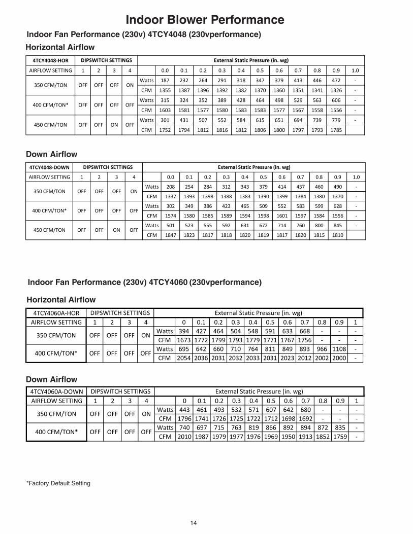
Indoor Blower PerformanceIndoor Fan Performance (230v) 4TCY4048 (230vperformance)
Down Airflow
Horizontal Airflow
Indoor Fan Performance (230v) 4TCY4060 (230vperformance)
Down Airflow
Horizontal Airflow
*Factory Default Setting
4TCY4048-HOR
AIRFLOW SETTING 1 2 3 4 0.0 0.1 0.2 0.3 0.4 0.5 0.6 0.7 0.8 0.9 1.0
Watts 187 232 264 291 318 347 379 413 446 472 -
CFM 1355 1387 1396 1392 1382 1370 1360 1351 1341 1326 -
Watts 315 324 352 389 428 464 498 529 563 606 -
CFM 1603 1581 1577 1580 1583 1583 1577 1567 1558 1556 -
Watts 301 431 507 552 584 615 651 694 739 779 -
CFM 1752 1794 1812 1816 1812 1806 1800 1797 1793 1785OFF
DIPSWITCH SETTINGS External Static Pressure (in. wg)
350 CFM/TON
400 CFM/TON*
450 CFM/TON
OFF OFF OFF ON
OFF OFF OFF OFF
OFF OFF ON
4TCY4048-DOWN
AIRFLOW SETTING 1 2 3 4 0.0 0.1 0.2 0.3 0.4 0.5 0.6 0.7 0.8 0.9 1.0
Watts 208 254 284 312 343 379 414 437 460 490 -
CFM 1337 1393 1398 1388 1383 1390 1399 1384 1380 1370 -
Watts 302 349 386 423 465 509 552 583 599 628 -
CFM 1574 1580 1585 1589 1594 1598 1601 1597 1584 1556 -
Watts 501 523 555 592 631 672 714 760 800 845 -
CFM 1847 1823 1817 1818 1820 1819 1817 1820 1815 1810
External Static Pressure (in. wg)DIPSWITCH SETTINGS
ON
OFF OFF OFF OFF
OFFONOFFOFF
350 CFM/TON
400 CFM/TON*
450 CFM/TON
OFF OFF OFF
4TCY4060A-HORAIRFLOW SETTING 1 2 3 4 0 0.1 0.2 0.3 0.4 0.5 0.6 0.7 0.8 0.9 1
Watts 394 427 464 504 548 591 633 668 - - -CFM 1673 1772 1799 1793 1779 1771 1767 1756 - - -
Watts 695 642 660 710 764 811 849 893 966 1108 -CFM 2054 2036 2031 2032 2033 2031 2023 2012 2002 2000 -
OFF OFF
DIPSWITCH SETTINGS
350 CFM/TON
400 CFM/TON*
External Static Pressure (in. wg)
OFF OFF OFF ON
OFF OFF
4TCY4060A-DOWNAIRFLOW SETTING 1 2 3 4 0 0.1 0.2 0.3 0.4 0.5 0.6 0.7 0.8 0.9 1
Watts 443 461 493 532 571 607 642 680 - - -CFM 1796 1741 1726 1725 1722 1712 1698 1692 - - -
Watts 740 697 715 763 819 866 892 894 872 835 -CFM 2010 1987 1979 1977 1976 1969 1950 1913 1852 1759 -
DIPSWITCH SETTINGS External Static Pressure (in. wg)
350 CFM/TON OFF OFF OFF ON
400 CFM/TON* OFF OFF OFF OFF

15
4TCY4048 AIRFLOW WITH AUXILIARY HEAT (CFM)
4TCY4036 AIRFLOW WITH AUXILIARY HEAT (CFM)
4TCY4024 AIRFLOW WITH AUXILIARY HEAT (CFM)
OFF OFF
50%
80%
100% if necessary
50%
Dehumidify
Fast Coil CoolingEfficiency
7.5minutes
3minutes
1minute
FA
N O
PE
RA
TIO
N (
CF
M)
COMPRESSOR OPERATION ON OFF
as required
4TCY4060 AIRFLOW WITH AUXILIARY HEAT (CFM)
Indoor Blower Performance
4TCY4030 AIRFLOW WITH AUXILIARY HEAT (CFM)
4TCY4042 AIRFLOW WITH AUXILIARY HEAT (CFM)
SELECTION NOMINAL AIRFLOW7-OFF 8-OFF LOW 1400 CFM7-ON 8-OFF HIGH 1600 CFM7-OFF 8-ON HIGH 1600 CFM7-ON 8-ON HIGH 1600 CFM
SWITCH SETTINGS
SELECTION NOMINAL AIRFLOW
7-OFF 8-OFF LOW 1050 CFM
7-ON 8-OFF HIGH 1200 CFM
7-OFF 8-ON HIGH 1200 CFM
7-ON 8-ON HIGH 1200 CFM
SWITCH SETTINGS
SELECTION NOMINAL AIRFLOW7-OFF 8-OFF LOW 700 CFM7-ON 8-OFF HIGH 800 CFM7-OFF 8-ON HIGH 800 CFM7-ON 8-ON HIGH 800 CFM
SWITCH SETTINGS
5-OFF 6-OFF NONE 100%5-ON 6-OFF 45 SEC 100%5-OFF 6-ON 90 SEC 50%5-ON 6-ON ** 50-100%
** This ENHANCED MODE selection provides a ramping up and ramping down of the indoor blower speed to provide improved comfort, quietness, and potential energy savings. The Graph below shows the ramping process
COOLING FAN DELAY OPTIONS
SWITCH SETTINGS DELAYNOMINAL AIRFLOW
Selection Normal Airflow
7-OFF 8-OFF LOW 1750 CFM
7-ON 8-OFF HIGH 2000 CFM
7-OFF 8-ON HIGH 2000 CFM
7-ON 8-ON HIGH 2000 CFM
Switch Setting
SELECTION NOMINAL AIRFLOW7-OFF 8-OFF LOW 1050 CFM7-ON 8-OFF HIGH 1200 CFM7-OFF 8-ON HIGH 1200 CFM7-ON 8-ON HIGH 1200 CFM
SWITCH SETTINGS
SELECTION NOMINAL AIRFLOW7-OFF 8-OFF LOW 1400 CFM7-ON 8-OFF HIGH 1600 CFM7-OFF 8-ON HIGH 1600 CFM7-ON 8-ON HIGH 1600 CFM
SWITCH SETTINGS

16
Typical Wiring

17
Typical Wiring

18
Optional Equipment
BAYCURB050A FULL PERIMETER ROOF MOUNTING CURB FOR *****024-036
14”
46 3/8
17 7/8
3
3 5/8
19 1/2
2 3/16
19 1/2
14
1 1/2
38 7/8
15
35 7/843 3/8
The drawings on this page are prepared by the manufacturer in order to provide detail regarding job layout only. These drawings are not intended to be used as a basis to construct, build or modify the items de-picted in the drawings. The manufacturer is not responsible for the unauthorized use of these drawings and expressly disclaims any liability for damages resulting from such unauthorized use.

19
Optional Equipment
BAYCURB051A Full Perimeter Roof Mounting Curb for *****042-060
56 1/8
15 7/8
3
10 7/819 1/2
4 3/4
19 1/2
14
41 7/8
20
1 1/2
38 7/8 53 1/8
The drawings on this page are prepared by the manufacturer in order to provide detail regarding job layout only. These drawings are not intended to be used as a basis to construct, build or modify the items de-picted in the drawings. The manufacturer is not responsible for the unauthorized use of these drawings and expressly disclaims any liability for damages resulting from such unauthorized use.

20
BAYECON101,102A Down Discharge Economizer and Rain Hood(Mounts Over Horizontal Return Air Opening)
A
B
C D
E
BAYECON200,201A Horizontal Economizer and Rain Hood
Return DuctRoofcurb
Relief damper
Mist elimi-nator
Economizer rain hood
HVAC Unit
Outside air dampers
Return air damp-ers
Required filter kit, order separately
A
Optional Equipment
Economizer
Gaskets (2)
Rain HoodDuct
The drawings on this page are prepared by the manufacturer in order to provide detail re-garding job layout only. These drawings are not intended to be used as a basis to con-struct, build or modify the items depicted in the draw-ings. The manufacturer is not responsible for the unauthor-ized use of these drawings and expressly disclaims any liability for damages resulting from such unauthorized use.
Mixed Air Sensor
Economizer Unit Application Models A
4TC*,WC*,YC*,DC*
*018-036
4TC*,WC*,YC*, DC*
*042-060
BAYECON101A
BAYECON102A
20.125"
24.375"
Economizer A B C D E F
BAYECON200AA 22" 20" 16-7/8" 15-11/16" 11-11/16" 15"
BAYECON201AA 26" 22-21/32" 19" 17-11/16" 14-11/16" 21-3/8"

21
A
B
CD
FULLYOPEN
2/31/3
FULLYCLOSED
BAYDMPR101,102A, 25% Motorized Outside Air Damper(Mounts Over Horizontal Return AIr Opening)
BAYOSAH001,002A, 25% Outside Air Damper(Replaces Filter/Coil Access Panel)
Optional Equipment
The drawings on this page are prepared by the manufacturer in order to provide detail regarding job layout only. These drawings are not intended to be used as a basis to construct, build or modify the items de-picted in the drawings. The manufacturer is not responsible for the unauthorized use of these drawings and expressly disclaims any liability for damages resulting from such unauthorized use.
D
C B
A
E
Manual Fresh Air Model
Unit Application Models
A B C D
BAYOSAH001
4YC,WC3018-036 4TC*3018-036,
4W/T/Y/DCY4024-036, 4W/Y/DCZ6036
22 7/16"" 20 11/16"" 12 3/8"" 9 3/16""
BAYOSAH002
4YC,WC3042-060, 4TC*3042-060,
4W/T/Y/DCY4042-060, 4W/Y/DCZ6048-060
25 3/16"" 20 11/16"" 12 3/8"" 9 3/16""
Unit Application Models A B C D E
BAYDMPR101A
4YC,WC3018-036 4TC*3018-036,
4W/T/Y/DCY4024-036, 4W/Y/DCZ6036
15 13/16"" 11 13/16"" 10 1/4"" 11 1/2"" 12 1/4""
BAYDMPR102A
4YC,WC3042-060, 4TC*3042-060,
4W/T/Y/DCY4042-060, 4W/Y/DCZ6048-060
18 3/16"" 15 1/8"" 10 1/4"" 11 1/2"" 12 1/4""

22
Optional Equipment
The drawings on this page are prepared by the manufacturer in order to provide detail regarding job layout only. These drawings are not intended to be used as a basis to construct, build or modify the items depicted in the drawings. The manufacturer is not responsible for the unauthorized use of these drawings and expressly disclaims any liability for damages resulting from such unauthorized use.
BAYFLTR101, 201B, 1" - 2" Filter Rack(Mounts in Filter/Coil Section)
BAYACCDOR1A & BAYACCDOR2A Hinged Filter Access DoorReplaces Filter/Coil Access Panel
Filter

23
Dimensional Data and Weights
4TCY4024 through 4TCY4036 (1 of 3)
NOTE: The view labeled “Bottom Side” represents the Base as viewed looking up from underneath the
unit.

24
Dimensional Data and Weights
4TCY4024 through 4TCY4036 (2 of 3)

25
Dimensional Data and Weights
4TCY4024 through 4TCY4036 (3 of 3)

26
Dimensional Data and Weights
4TCY4042 through 4TCY4060 (1 of 3)
NOTE: The view labeled “Bottom Side” represents the Base as viewed looking up from underneath the
unit.

27
Dimensional Data and Weight
4TCY4042 through 4TCY4060 (2 of 3)

28
Dimensional Data and Weight
4TCY4042 through 4TCY4060 (3 of 3)

29
Mechanical Specifications
Trane has a policy of continuous product and product data improvement and it reserves the right to change design
and specifications without notice.
Trane6200 Troup HighwayTyler, TX 75707-9010
GeneralThe units shall be horizontal airflow as shipped and convertible to downflow. All units shall be factory assembled, piped, in-ternally wired and fully charged with R-22. All units shall be factory run tested to check cooling operation, fan and blower rotation and control sequence. Units shall be designed to operate at ambient temperatures between 55°F and 115°F in cooling as manufactured. Cooling performance shall be rated in accor-dance with A.H.R.I. standards.
Unit CasingAll panels shall be heavy gauge steel, gas-keted and insulated. Foil-faced fiber insula-tion shall be in the heater section. Foil-faced fiber insulation shall be in the evaporator section. Base pan shall be heavy gauge steel. WEATHERGUARD™ exterior corrosion resistant screws shall be used for added resistance to rust and corrosion.
CompressorThe compressor shall be a hermetically sealed, high efficiency Climatuff® com-pressor. Internal overcurrent and over temperature protection, internal pressure relief shall be standard. Other features include, centrifugal oil pump and low vibra-tion and noise.
Refrigeration SystemAll units shall have refrigerant control. Service pressure tap ports, and a refrigerant line filter shall be standard.
Evaporator Coil Internally enhanced 3/8-inch OD seamless copper tubing me chani cally bonded to alu-minum fins, factory pressure and leak tested at 250 to 300 psig. All units have a TXV to control refrigerant flow.
Condenser CoilThe Spine Fin™condenser coil shall be continuously wrapped, corrosion resis-tant all aluminum with minimum brazed joints. This coil is 3/8 inch O.D. seamless aluminum tubing glued to a continuous aluminum fin. Coils are lab tested to withstand 2,000 pounds of pressure per square inch. The outdoor coil provides low airflow resistance and efficient heat transfer. The coil is protected on all four sides by louvered panels.
Indoor Air FanDirect-drive, forward-curved, centrifugal wheel in a Composite Vortica® Blower housing. Motor shall have thermal overload protection and permanently lubricated motor bearings. Motor/blower assembly isolated from unit with rubber mounts.
Outdoor FanOne direct-drive, statically and dynami-cally balanced propeller fan shall be used in a draw through configuration. Permanently lubricated weather proof motor shall have built-in thermal overload protection.
System ControlsSystem controls include condenser fan, evaporator fan and compressor contactors.
Accessories Roof Curb The roof curb shall be designed to mate with the unit and provide support and complete weathertight installation when properly in-stalled. Adhesive back polyurethane sealing strips shall be provided to ensure an airtight seal between supply and return openings of the curb and unit. The roof curb design allows field fabricated ductwork to be connected directly to the curb. Curb ships knocked down for field assembly, and includes factory-in-stalled wood nailer strips.
Electric Heaters Each heater assembly shall include power supply fusing if over 48 amps, automatic resetting limit switches and heat limiters for thermal protection. Heaters shall be provided with polarized plugs for quick connection to unit low voltage wiring.
Single Source Power EntryThis accessory, when used with electric heat accessory, shall allow single source power connection to unit and heater com-bination. Single source power entry kits shall have specific matching heater(s). Kit shall include high voltage terminal blocks, fuse blocks and fuses, cut-to-length in-terconnecting wiring, and junction box (if required) to provide power sources with fuse protection as required for both the unit and accessory heater. Kit components shall install within the heater cabinet in the heater access section. Single source branch power circuit shall be protected and wired in accordance with local codes.
Fully Modulating EconomizerThis accessory shall be field installed and be composed of the following items: 0-100% fresh air damper, damper drive motor, fixed dry bulb enthalpy control, and low voltage pigtails for electrical connections. Solid state enthalpy or differential enthalpy control is optional. Economizer operations shall be controlled by the preset position of the enthalpy control. A barometic relief damper shall be standard with the downflow economizer and provide a pressure operated damper that shall be gravity closing and prohibit entrance of outside air on equipment “off” cycle.
Manual Outside Air DampersRain hood and screen shall be field installed. Suitable for up to 25% outside air.
Start Kit Extra compressor starting capacity for single phase equipment.
Control Options Standard Indoor Thermostats Two stage heating/cooling or one stage heat-ing/cooling thermostats shall be available in either manual or automatic changeover.
Programmable Electronic Night Setback Thermostat Programmable electronic thermostat shall provide heating setback and cooling setup with 7-day, programming capability. 1 H/1 C or 2H/2C models available.