2240 ds 20130827 - ien europe · rtu and plc in a single system. ... sel-3530 rtac connects via ......
TRANSCRIPT

Schweitzer Engineering Laboratories, Inc. SEL-2240 Data Sheet
Rugged Digital I/O, Analog Inputs, Current and Voltage Measurements and Control for
Your Toughest Applications
The SEL Axion® is a fully integrated modular digital I/O, analog input, current and voltage measurement, and controlsolution suitable for many utility and industrial applications. It combines the communications, built-in security, andIEC 61131 logic engine of the SEL Real-Time Automation Controller (RTAC) family with a durable suite of I/Omodules that provide high-speed, deterministic, control performance over an EtherCAT network.
Major Features and Benefits➤ Synchronized Current and Voltage Measurements. The Axion CT/PT module provides high-accu-
racy current and voltage measurements with the advantage of synchronized measurements. MultipleCT/PT modules in an Axion system sample all measurements at the same time to ensure a commonreference for all voltages and currents. This enables many time deterministic control applications with-out performing additional processing to align the measurements to a reference. Utilize this capabilityto accomplish complex control schemes including load shedding, microgrid control, and autosynchro-nization.
➤ Top of Second Synchronized Measurements. When connected to IRIG, the Axion synchronizes themeasurement of all CT/PT modules to the top of the second. This enables Axions in geographicallydispersed locations to run algorithms on voltage and current measurements and provide time-aligneddata from all of the Axion modules. This expands time-deterministic control capability to wide-areaapplications since the CT/PT measurements from multiple Axion systems are all synchronized.
➤ RTU and PLC in a Single System. Employ the Axion’s I/O, SCADA communications, and controllogic support in many industrial and utility applications.
➤ Simple Setup With ACSELERATOR RTAC® SEL-5033 Software. Use standard device templates tobuild a system, including I/O modules, quickly.
SEL-2240 Axion
SEL-2240 Data Sheet Schweitzer Engineering Laboratories, Inc.
2
➤ Flexible I/O Selections. Choose a custom mix of digital and analog I/O modules that suit the applica-tion. Include hundreds of points in a single panel, all connected to a deterministic EtherCAT® network.
➤ Advanced User Authentication and System Security. Enforce LDAP user accounts to maintainsecurity perimeter integrity. Apply corporate logging and port control policies to comply withNERC/CIP requirements.
➤ Integrated Web-Based Human-Machine Interface (HMI). Integrate the SEL-2241 RTAC moduledirectly into the Axion system. The RTAC, via the embedded web server, includes a flexible graphicalHMI system.
➤ Deterministic I/O Performance. Update connected I/O at a deterministic frequency; all inputs pro-vide 1 ms Sequential Events Recorder (SER) timestamps.
➤ More than SCADA. Go beyond SCADA using the Axion’s industry-standard communications proto-cols to enable multiple SCADA connections, as well as distributed control networks, among many sta-tions.
➤ Networking Options. Implement I/O networks that use optional fiber-optic cables to provide out-standing signal isolation and flexibility in module placement.
➤ Standard IEC 61131-3 Logic Design. Create innovative logic solutions directly in ACSELERATORRTAC by using editor tools such as Ladder Diagram, Tag Processor, Structured Text, or ContinuousFunction Chart.
➤ Redundant Power Supplies. Install optional dual SEL-2243 power couplers for applications needingredundant power sources.
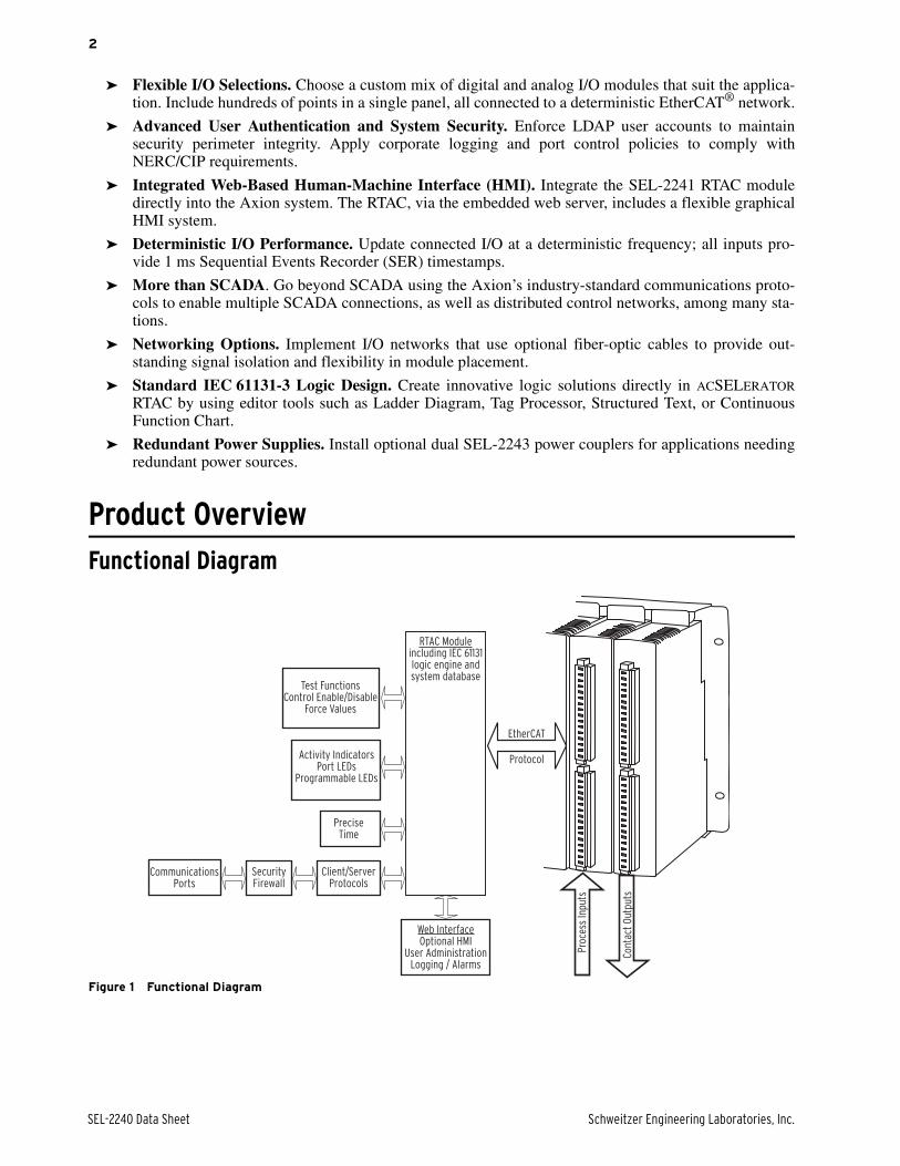
Product OverviewFunctional Diagram
Figure 1 Functional Diagram
EtherCAT
Protocol
CommunicationsPorts
SecurityFirewall
Client/ServerProtocols
PreciseTime
Web InterfaceOptional HMI
User AdministrationLogging / Alarms
Activity IndicatorsPort LEDs
Programmable LEDs
Test FunctionsControl Enable/Disable
Force Values
Proc
ess
Inpu
ts
Cont
act
Out
puts
RTAC Moduleincluding IEC 61131logic engine andsystem database

Schweitzer Engineering Laboratories, Inc. SEL-2240 Data Sheet
3
Flexible System ArchitectureToday's monitoring and control applications needflexible system architectures and integrated security. TheAxion meets these needs by using SEL RTAC modulesas the system CPU. Two configurations are possible.There can be an SEL-2241 RTAC module installeddirectly in the Axion node, or the node can be connectedto a stand-alone RTAC module. SEL-3530 RTACconnects via Ethernet to an SEL-2240 node. SEL designsall Axion hardware to published standards (seeSpecifications) and performs tests to verify that eachcomponent exceeds standards by adequate margins. ThePower Coupler module (model SEL-2243) is a highly
reliable device that uses the same power supplytechnology presently in use in SEL protective relays.Configure the SEL Axion to include single or redundantpower couplers for critical applications. In redundantconfigurations, the pair of SEL-2243 modules activelyshare loads to supply power for the entire node. If onemodule should become unavailable, the remaining powercoupler can accommodate the entire node with no loss ofsystem capability. Employ dual power couplers forinstallations where you have dual power sources, onethat is AC and one that is DC.
Figure 2 Modules Installed in Chassis/Backplane With Spare Slots
Each Axion node is mounted in a chassis/backplane(model SEL-2242) that provides a means for each nodeto include a custom arrangement of modules. A singlenode can contain as many as nine modules. Use anycombination, quantity, and sequence of modules thatsuits the application.
The node does not need to be entirely full to functionproperly. Leave empty slots for future expansion asnecessary. Many RTU and control systems need moreI/O points than will fit in a single Axion node. In thosecases, use the EtherCAT protocol to connect multiplenodes together via a real-time Ethernet network. Throughuse of an Axion system EtherCAT network, you can useas many as 60 modules in a single network with no lossof speed or determinism. The Applications sectionexplores a number of possible network configurations. Ineach implementation, a single RTAC module provideslogic functions and data concentration for the entirenetwork.
RTU and PLC FunctionalityThe Axion is both a remote terminal unit (RTU) andultra-rugged programmable logic controller (PLC). Allof the modules are rated from –40°C to +85°C and canoptionally include conformal coating. The system isdesigned to be flexible; use the right combination ofmodules and nodes, in almost any arrangement, to suitthe job. The SEL-2244 Digital Output Module has trip-rated contacts (30 A make, 6 A carry) to limit the needfor interposing relays.
The SEL-2241, SEL-3530, and SEL-3530-4 RTACs allinterface seamlessly with the I/O modules and provideeasy integration with other serial and Ethernet devicesvia pre-installed communications protocols. The RTACsalso support multiple SCADA/HMI channels. For highspeed communication, use EtherCAT fieldbusconnections to I/O modules or optional IEC 61850GOOSE messaging with station IEDs. Poll data sets andreports from other IEDs with optional IEC 61850 MMSclient.

SEL-2240 Data Sheet Schweitzer Engineering Laboratories, Inc.
4
With the Axion, you need no optional hardware orsoftware to have the programmable logic engine requiredfor many applications. Each RTAC includes anIEC 61131 logic engine that ships preconfigured toprovide access for all system tags, intelligent electronicdevice (IED) and I/O data, diagnostics, alarms, securityevents, and communications statistics. The RTACprovides unified tag mapping between protocols andprogrammable logic which simplifies developingapplications. You simply use any necessary IED and I/Odata, calculated values, and system tags in deterministiclogic for the control of critical applications.
Management of the task processing sequence and solverate in the RTAC is similar to that for traditional PACs.Optimize processor use by setting the processing rate nofaster than necessary for your application.
Task processing in the logic engine includes protocols,I/O, system management, and any custom logicprograms you create using Structured Text (ST), LadderLogic Diagrams (LD), or Continuous Function Charts(CFC). CFC programs are type of IEC 61131-3 FunctionBlock Diagram (FBD) that provide more programmingflexibility than standard FBDs. The ACSELERATOR
RTAC software, free of charge with purchase of an SELRTAC, includes the IEC 61131-3 and Tag Processoreditors you will use to manage any protocol informationand custom logic necessary for your system.
Secure OperationYou can use the built-in web interface to manage useraccounts and system alarms remotely. Each user accounthas a unique user name, password, and assigned role thatdefines system permissions. You can also configure thesystem to use LDAP central authentication for useraccount management. There are web pages formonitoring user logs and maintaining network policies.
By enabling Ethernet and serial ports independently, youcan minimize any security threat from unused butenabled ports. Employ SSH encryption for remoteengineering access to further protect the system.Combine the Axion with other SEL security solutions tosimply deploy a solution that meets your needs formaintaining a secure electronic perimeter for the controlsystem.
Seamless System ConfigurationACSELERATOR RTAC is a Microsoft Windows-compatible configuration software for offline and onlineuse with the SEL-2241, SEL-3530, and SEL-3530-4
RTACs. A project in ACSELERATOR RTAC contains thecomplete configuration, settings, and logic for anindividual RTAC device. Preconfigured device and I/Omodule templates are available for you to quickly createall device and master connections for the project.
Once you create the settings for a specific deviceconnection, improve engineering efficiency by saving acustom device template for later use with similarprojects. Share custom templates via email or networkfor even greater savings. The application also includescomplete project templates for some common projecttypes.
Use the intuitive ribbon interface, as shown in Figure 3,to configure all of the I/O modules and deviceconnections for the project. The Project View in the leftpane lets you organize and quickly see everything in theproject.
Figure 3 Adding SEL-2240 I/O Modules to a Project
The Tag Processor view facilitates the mapping ofoperational data between IEDs and SCADA.ACSELERATOR RTAC is compatible with MicrosoftExcel and other programs, so you can save time andincrease accuracy by copying SCADA maps from thesource document.
There is no need to install or learn more than onesoftware interface. Use the included Structured Text,Ladder Diagram, or Continuous Function Chart editorsto develop custom IEC 61131 logic.
Enable remote monitoring and control functions by usingthe optional web-based HMI for any of the RTACdevices. Figure 4 shows an example of a screen
Schweitzer Engineering Laboratories, Inc. SEL-2240 Data Sheet
5
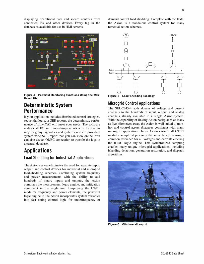
displaying operational data and secure controls fromconnected I/O and other devices. Every tag in thedatabase is available for use in HMI screens.
Figure 4 Powerful Monitoring Functions Using the Web-Based HMI
Deterministic System PerformanceIf your application includes distributed control strategies,sequential logic, or SER reports, the deterministic perfor-mance of EtherCAT will meet your needs. The softwareupdates all I/O and time-stamps inputs with 1 ms accu-racy. Log any tag values and system events to provide asystem-wide SOE report that you can view online. Youcan also use an ODBC connection to transfer the logs toa central database.
ApplicationsLoad Shedding for Industrial Applications
The Axion system eliminates the need for separate input,output, and control devices for industrial and microgridload-shedding schemes. Combining system frequencyand power measurements with the ability to addhundreds of binary inputs and outputs, the Axioncombines the measurement, logic engine, and mitigationequipment into a single unit. Employing the CT/PTmodule’s frequency and power elements, the powerfullogic engine in the Axion incorporates system variablesinto fast acting control logic for underfrequency or
demand control load shedding. Complete with the HMI,the Axion is a standalone control system for manyremedial action schemes.
Figure 5 Load-Shedding Topology
Microgrid Control ApplicationsThe SEL-2245-4 adds dozens of voltage and currentchannels to the hundreds of input, output, and analogchannels already available in a single Axion system.With the capability of linking Axion backplanes as manyas five kilometers away, the Axion is well suited to mon-itor and control across distances consistent with manymicrogrid applications. In an Axion system, all CT/PTmodules sample at precisely the same time, ensuring acommon reference for all voltages and currents enteringthe RTAC logic engine. This synchronized samplingenables many unique microgrid applications, includingislanding detection, generation restoration, and dispatchalgorithms.
Figure 6 Offshore Microgrid
BUS A
BUS B
G1 Utility Tie
SEL-2240 Data Sheet Schweitzer Engineering Laboratories, Inc.
6
Autosynchronization SystemsUse multiple CT/PT and I/O modules to create advancedand highly scalable autosynchronization systems. Auto-matically adjust the governor exciter controls as neces-sary to provide safe, secure, and unattendedsynchronization of generation onto the power system.With synchronized sampling from multiple CT/PT mod-ules, the control algorithm for multiple governor excitersall have access to all necessary PT measurements in thesame Axion system. Additionally, the measurements arealready time-aligned, eliminating the need to adjust to acommon reference. An added bonus is that the CT/PTmodules can be located remotely across the system andprovide the synchronized measurements through theAxion’s deterministic EtherCAT network.
Figure 7 SEL Axion Autosynchronization System
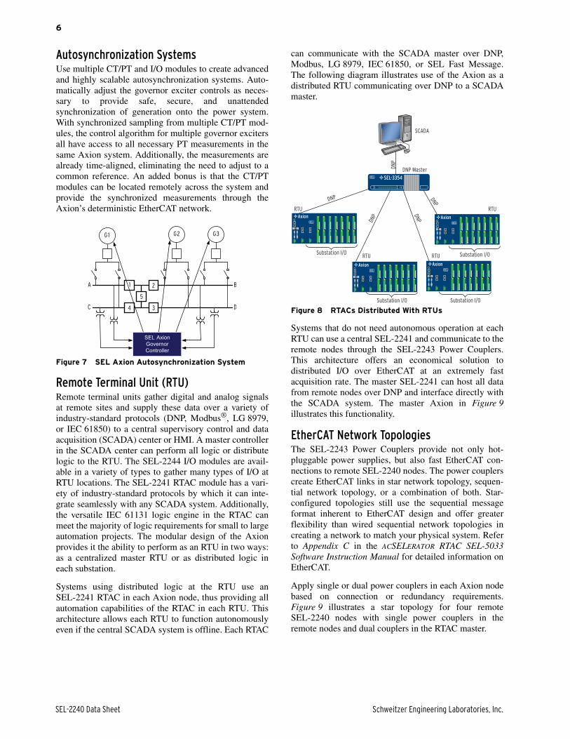
Remote Terminal Unit (RTU)Remote terminal units gather digital and analog signalsat remote sites and supply these data over a variety ofindustry-standard protocols (DNP, Modbus®, LG 8979,or IEC 61850) to a central supervisory control and dataacquisition (SCADA) center or HMI. A master controllerin the SCADA center can perform all logic or distributelogic to the RTU. The SEL-2244 I/O modules are avail-able in a variety of types to gather many types of I/O atRTU locations. The SEL-2241 RTAC module has a vari-ety of industry-standard protocols by which it can inte-grate seamlessly with any SCADA system. Additionally,the versatile IEC 61131 logic engine in the RTAC canmeet the majority of logic requirements for small to largeautomation projects. The modular design of the Axionprovides it the ability to perform as an RTU in two ways:as a centralized master RTU or as distributed logic ineach substation.
Systems using distributed logic at the RTU use anSEL-2241 RTAC in each Axion node, thus providing allautomation capabilities of the RTAC in each RTU. Thisarchitecture allows each RTU to function autonomouslyeven if the central SCADA system is offline. Each RTAC
can communicate with the SCADA master over DNP,Modbus, LG 8979, IEC 61850, or SEL Fast Message.The following diagram illustrates use of the Axion as adistributed RTU communicating over DNP to a SCADAmaster.
Figure 8 RTACs Distributed With RTUs
Systems that do not need autonomous operation at eachRTU can use a central SEL-2241 and communicate to theremote nodes through the SEL-2243 Power Couplers.This architecture offers an economical solution todistributed I/O over EtherCAT at an extremely fastacquisition rate. The master SEL-2241 can host all datafrom remote nodes over DNP and interface directly withthe SCADA system. The master Axion in Figure 9illustrates this functionality.
EtherCAT Network TopologiesThe SEL-2243 Power Couplers provide not only hot-pluggable power supplies, but also fast EtherCAT con-nections to remote SEL-2240 nodes. The power couplerscreate EtherCAT links in star network topology, sequen-tial network topology, or a combination of both. Star-configured topologies still use the sequential messageformat inherent to EtherCAT design and offer greaterflexibility than wired sequential network topologies increating a network to match your physical system. Referto Appendix C in the ACSELERATOR RTAC SEL-5033Software Instruction Manual for detailed information onEtherCAT.
Apply single or dual power couplers in each Axion nodebased on connection or redundancy requirements.Figure 9 illustrates a star topology for four remoteSEL-2240 nodes with single power couplers in theremote nodes and dual couplers in the RTAC master.
G1 G2 G3
1 2
5
34
A
C
B
D
SEL AxionGovernor Controller
SCADA
DNP Master
DNP
DNP DN
P
DN
P
Substation I/O
RTU
DNP
Substation I/O
Substation I/O
Substation I/ORTU RTU
RTU
SEL-3354
Axion
Axion Axion
Axion

Schweitzer Engineering Laboratories, Inc. SEL-2240 Data Sheet
7
Figure 9 EtherCAT Star Network Topology
Figure 10 illustrates connections for an EtherCATsequential topology with six Axion nodes. Each nodeuses a single SEL-2243 Power Coupler to provideconnections to the previous and next node in theEtherCAT network.
Figure 10 EtherCAT Sequential Network Topology
Figure 11 illustrates a combination of star and sequentialconnections with six Axion nodes.
Figure 11 EtherCAT Hybrid Network Topology
Remote I/OWhen you use single or dual power couplers, the Axionserves as a low-cost remote I/O module. As many as60 modules or six nodes can connect to one residentSEL-2241 RTAC or to a separate SEL-3530 RTAC. TheAxion is an excellent teleprotection device that providesthrough EtherCAT a simple means for expanding thenumber of I/O points available in an automation systemat rapid data acquisition rates.
Figure 12 Remote I/O Configuration
IEC 61850 GOOSE ConcentratorGather a variety of substation I/O with the SEL-2244modules and share the data with IEC 61850 GenericObject-Oriented Substation Event (GOOSE) messages.Use the protocol flexibility of the RTAC to concentratedata from non-IEC 61850 relays and convert these datato GOOSE messages.
Figure 13 IEC 61850 Goose Concentrator
RTAC Master
Axion
Axion Axion
AxionAxion
RTAC Master
AxionAxion
Axion
Axion
AxionAxion
RTAC Master
Axion
Axion
Axion Axion Axion
Axion
Axion
Substation I/O
GO
OSE
SEL-300G
SEL-387SEL-701
Axion
SEL-2240 Data Sheet Schweitzer Engineering Laboratories, Inc.
8
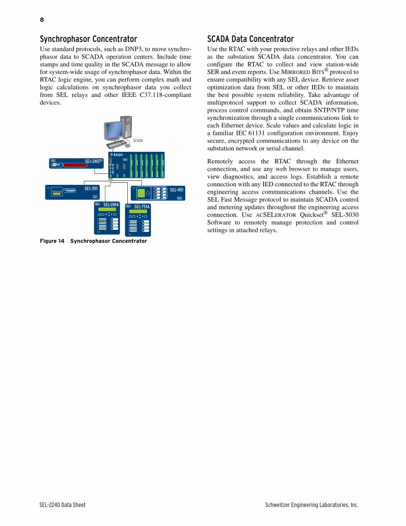
Synchrophasor ConcentratorUse standard protocols, such as DNP3, to move synchro-phasor data to SCADA operation centers. Include timestamps and time quality in the SCADA message to allowfor system-wide usage of synchrophasor data. Within theRTAC logic engine, you can perform complex math andlogic calculations on synchrophasor data you collectfrom SEL relays and other IEEE C37.118-compliantdevices.
Figure 14 Synchrophasor Concentrator
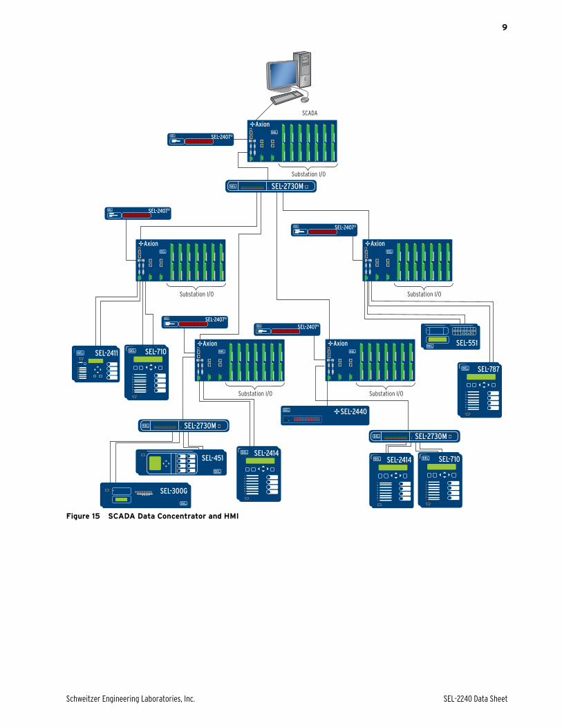
SCADA Data ConcentratorUse the RTAC with your protective relays and other IEDsas the substation SCADA data concentrator. You canconfigure the RTAC to collect and view station-wideSER and event reports. Use MIRRORED BITS® protocol toensure compatibility with any SEL device. Retrieve assetoptimization data from SEL or other IEDs to maintainthe best possible system reliability. Take advantage ofmultiprotocol support to collect SCADA information,process control commands, and obtain SNTP/NTP timesynchronization through a single communications link toeach Ethernet device. Scale values and calculate logic ina familiar IEC 61131 configuration environment. Enjoysecure, encrypted communications to any device on thesubstation network or serial channel.
Remotely access the RTAC through the Ethernetconnection, and use any web browser to manage users,view diagnostics, and access logs. Establish a remoteconnection with any IED connected to the RTAC throughengineering access communications channels. Use theSEL Fast Message protocol to maintain SCADA controland metering updates throughout the engineering accessconnection. Use ACSELERATOR Quickset® SEL-5030Software to remotely manage protection and controlsettings in attached relays.
SCADA
SEL-2407®
SEL-451SEL-351
SEL-2414 SEL-751A
Axion
Schweitzer Engineering Laboratories, Inc. SEL-2240 Data Sheet
9
Figure 15 SCADA Data Concentrator and HMI
SEL-2414SEL-2414
SEL-300G
SEL-451
SEL-787
SEL-551
SEL-710
SEL-2411 SEL-710
SCADA
SEL-2407®
Substation I/O
SEL-2407®
Substation I/O
SEL-2407®
Substation I/O
SEL-2407®
Substation I/O
SEL-2414SEL-2414
SEL-300G
SEL-451
SEL-2440
SEL-787
SEL-551
SEL-710
SEL-2411
SEL-2407®
Substation I/O
SEL-710Axion Axion
AxionAxion
Axion
SEL-2730M
SEL-2730MSEL-2730M

SEL-2240 Data Sheet Schweitzer Engineering Laboratories, Inc.
10
Human-Machine InterfaceUse the built-in web human-machine interface (HMI) in the RTAC for viewing and controlling any tags you configuredin the RTAC. Use ACSELERATOR Diagram Builder to develop custom HMI screens and load them into the RTAC. Youcan include one-line diagrams, annunciators, and graphical representations that contain control buttons, and you can thendisplay any data in the RTAC. Once you have loaded the screens into the RTAC, you can view the screens in the RTACweb interface. Since the HMI application is web-based, multiple users can view the HMI screens simultaneously.
Figure 16 HMI Oneline
The logging system in the RTAC providescomprehensive logging for all variables in the RTAC,including those that connected IEDs provide. Thelogging system compensates for time-stamp differentialamong data from different IEDS, so all data are insequence and on the same time-stamp reference. TheRTAC can log data for changes in the state of Booleanvalues, changes in string values, and changes in Boolean,analog, or string time stamps. The RTAC can also alarmfor analog values that cross defined thresholds. Assign
variables for logging in the Tag Processor, or use one ofthe logger function blocks in IEC 61131 customprograms.
There are two user interfaces for viewing logged data.These include a secure HTML interface and an opendatabase connectivity (ODBC) connection. Access theHTML interface through a web browser connection. Usethe ODBC connection for standard data transfer betweenthe logged data and database or spreadsheet software.
Schweitzer Engineering Laboratories, Inc. SEL-2240 Data Sheet
11
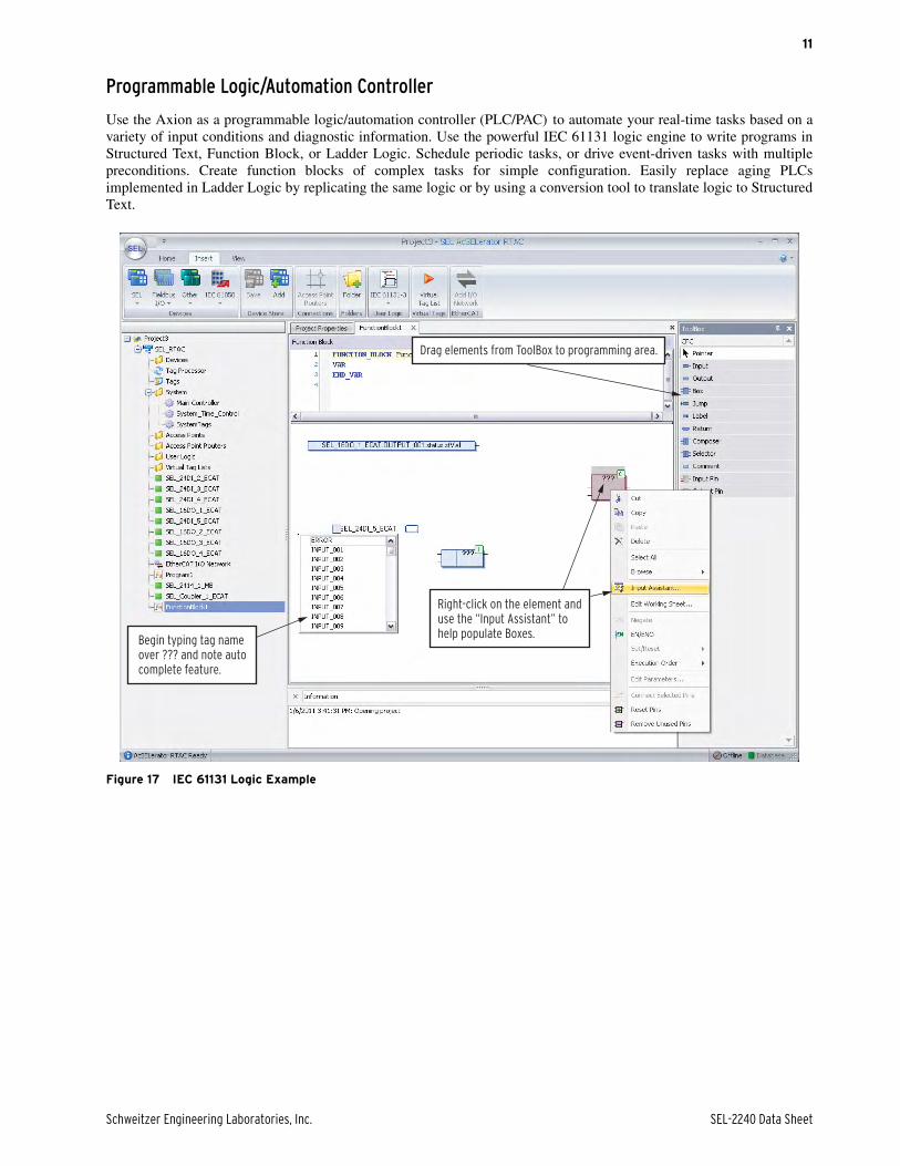
Programmable Logic/Automation Controller
Use the Axion as a programmable logic/automation controller (PLC/PAC) to automate your real-time tasks based on avariety of input conditions and diagnostic information. Use the powerful IEC 61131 logic engine to write programs inStructured Text, Function Block, or Ladder Logic. Schedule periodic tasks, or drive event-driven tasks with multiplepreconditions. Create function blocks of complex tasks for simple configuration. Easily replace aging PLCsimplemented in Ladder Logic by replicating the same logic or by using a conversion tool to translate logic to StructuredText.
Figure 17 IEC 61131 Logic Example
Begin typing tag nameover ??? and note autocomplete feature.
Right-click on the element anduse the “Input Assistant” tohelp populate Boxes.
Drag elements from ToolBox to programming area.
SEL-2240 Data Sheet Schweitzer Engineering Laboratories, Inc.
12
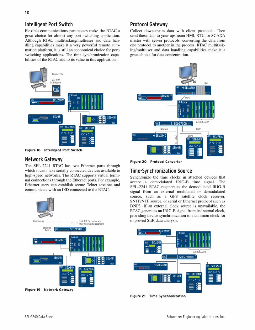
Intelligent Port SwitchFlexible communications parameters make the RTAC agreat choice for almost any port-switching application.Although RTAC multitasking/multiuser and data han-dling capabilities make it a very powerful remote auto-mation platform, it is still an economical choice for port-switching applications. The time-synchronization capa-bilities of the RTAC add to its value in this application.
Figure 18 Intelligent Port Switch
Network GatewayThe SEL-2241 RTAC has two Ethernet ports throughwhich it can make serially connected devices available tohigh-speed networks. The RTAC supports virtual termi-nal connections through the Ethernet ports. For example,Ethernet users can establish secure Telnet sessions andcommunicate with an IED connected to the RTAC.
Figure 19 Network Gateway
Protocol GatewayCollect downstream data with client protocols. Thensend these data to your upstream HMI, RTU, or SCADAmaster with server protocols, converting the data fromone protocol to another in the process. RTAC multitask-ing/multiuser and data handling capabilities make it agreat choice for data concentration.
Figure 20 Protocol Converter
Time-Synchronization SourceSynchronize the time clocks in attached devices thataccept a demodulated IRIG-B time signal. TheSEL-2241 RTAC regenerates the demodulated IRIG-Bsignal from an external modulated or demodulatedsource, such as a GPS satellite clock receiver,SNTP/NTP source, or serial or Ethernet protocol such asDNP3. If an external clock source is unavailable, theRTAC generates an IRIG-B signal from its internal clock,providing device synchronization to a common clock forimproved SER data analysis.
Figure 21 Time Synchronization
Engineering
SEL-2407®
SEL-451SEL-351
SEL-2414 SEL-751A
Axion
SEL-9192
SEL-9192USB Modem
Engineering
EthernetSwitch
SSH, TLS Encryption andUser Account Management
SEL-2407®
SEL-451SEL-351
SEL-2414 SEL-751A
Axion
SEL-2730M
HMI
DNP3
DNP3
DNP3
Modbus
IEC
618
50
SEL-2407®
SEL-451
SEL-2414SEL-751ASEL-2440
Substation I/O
SEL-3354
Axion
SEL-2730M
SEL-2407®
SEL-451SEL-2414
SEL-751ASEL-2440
Substation I/O
SEL-2411
Axion
SEL-2730M
Schweitzer Engineering Laboratories, Inc. SEL-2240 Data Sheet
13
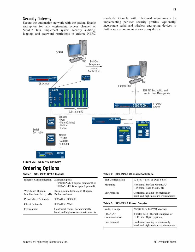
Security GatewaySecure the automation network with the Axion. Enableencryption for any engineering access channel orSCADA link. Implement system security auditing,logging, and password restrictions to enforce NERC
standards. Comply with role-based requirements byimplementing per-user security profiles. Optionally,incorporate serial and wireless encrypting devices tofurther secure communications to any device.
Figure 22 Security Gateway
Ordering Options
GPS ClockEngineering
EthernetSwitch
SSH, TLS Encryption and User Account Management
SerialEncryption
SCADA
AlarmNotification
Sensors- Door- Panel/Cabinet- Motion- Fence. . .
Alarms- Visible- Audible- Lighting. . .
Dial-OutTelephone
SEL-751A
SEL-2407®
SEL-2440
SEL-351
SEL-751A
SEL-3010
Substation I/O
Axion
SEL-2730M
SEL-3025
SEL-3025
Table 1 SEL-2241 RTAC Module
Ethernet Communication 2 Ethernet ports:10/100BASE-T copper (standard) or100BASE-FX fiber optic (optional)
Web-based Human-Machine Interface (HMI)
Basic runtime license and Diagram Builder software
Peer-to-Peer Protocols IEC 61850 GOOSE
Client Protocols IEC 61850 MMS
Environment Conformal coating for chemically harsh and high-moisture environments
Table 2 SEL-2242 Chassis/Backplane
Slot Configuration 10-Slot, 4-Slot, or Dual 4-Slot
Mounting Horizontal Surface Mount, 5UHorizontal Rack Mount, 5U
Environment Conformal coating for chemically harsh and high-moisture environments
Table 3 SEL-2243 Power Coupler
Voltage Range 24/48Vdc or 120/250 Vac/Vdc
EtherCAT Communication
2 ports: RJ45 Ethernet (standard) or LC Fiber Optic (optional)
Environment Conformal coating for chemically harsh and high-moisture environments
SEL-2240 Data Sheet Schweitzer Engineering Laboratories, Inc.
14
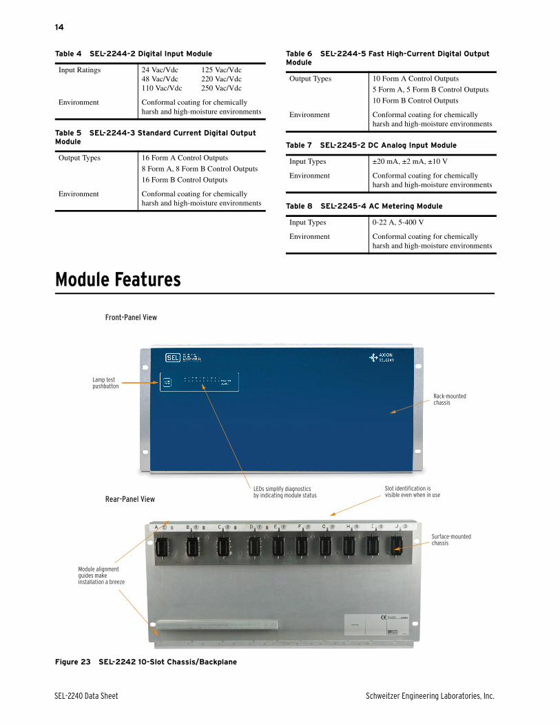
Module Features
Figure 23 SEL-2242 10-Slot Chassis/Backplane
Table 4 SEL-2244-2 Digital Input Module
Input Ratings 24 Vac/Vdc 125 Vac/Vdc48 Vac/Vdc 220 Vac/Vdc110 Vac/Vdc 250 Vac/Vdc
Environment Conformal coating for chemically harsh and high-moisture environments
Table 5 SEL-2244-3 Standard Current Digital Output Module
Output Types 16 Form A Control Outputs
8 Form A, 8 Form B Control Outputs
16 Form B Control Outputs
Environment Conformal coating for chemically harsh and high-moisture environments
Table 6 SEL-2244-5 Fast High-Current Digital Output Module
Output Types 10 Form A Control Outputs
5 Form A, 5 Form B Control Outputs
10 Form B Control Outputs
Environment Conformal coating for chemically harsh and high-moisture environments
Table 7 SEL-2245-2 DC Analog Input Module
Input Types ±20 mA, ±2 mA, ±10 V
Environment Conformal coating for chemically harsh and high-moisture environments
Table 8 SEL-2245-4 AC Metering Module
Input Types 0-22 A, 5-400 V
Environment Conformal coating for chemically harsh and high-moisture environments
Rack-mounted chassis
Surface-mountedchassis
Slot identification is visible even when in use
LEDs simplify diagnosticsby indicating module status
Module alignmentguides makeinstallation a breeze
Lamp testpushbutton
Front-Panel View
Rear-Panel View

Schweitzer Engineering Laboratories, Inc. SEL-2240 Data Sheet
15
Figure 24 SEL-2242 4-Slot Chassis/Backplane
Figure 25 SEL-2242 Dual 4-Slot Chassis/Backplane
Rack-mounted chassis
Surface-mountedchassis
Slot identification is visible even when in useLEDs simplify diagnostics
by indicating module status
Module alignmentguides makeinstallation a breeze
Lamp testpushbutton
Front-Panel View Rear-Panel View
Rack-mounted chassis
Surface-mountedchassis
Slot identification is visible even when in use
LEDs simplify diagnosticsby indicating module status
Module alignmentguides makeinstallation a breeze
Lamp testpushbutton
Front-Panel View
Rear-Panel View
SEL-2240 Data Sheet Schweitzer Engineering Laboratories, Inc.
16
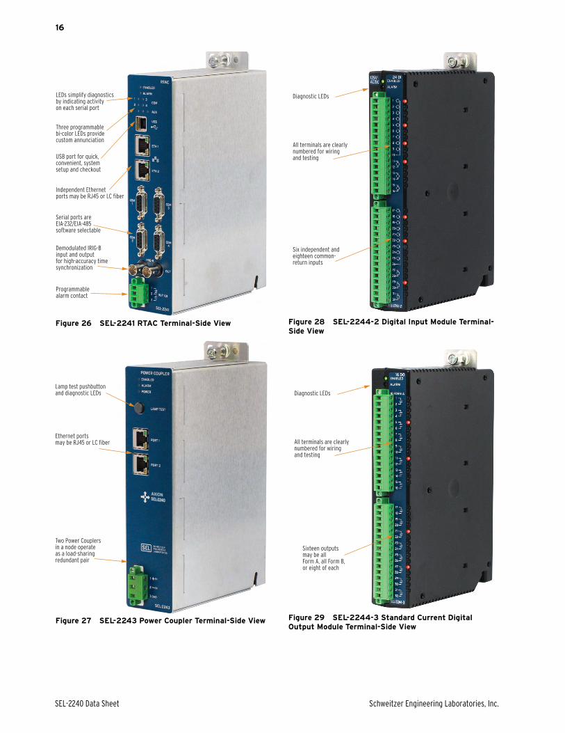
Figure 26 SEL-2241 RTAC Terminal-Side View
Figure 27 SEL-2243 Power Coupler Terminal-Side View
Figure 28 SEL-2244-2 Digital Input Module Terminal-Side View
Figure 29 SEL-2244-3 Standard Current Digital Output Module Terminal-Side View
Demodulated IRIG-Binput and output for high-accuracy timesynchronization
USB port for quick,convenient, systemsetup and checkout
Three programmablebi-color LEDs provide custom annunciation
LEDs simplify diagnosticsby indicating activityon each serial port
Independent Ethernetports may be RJ45 or LC fiber
Serial ports are EIA-232/EIA-485software selectable
Programmablealarm contact
Two Power Couplersin a node operateas a load-sharing redundant pair
Lamp test pushbuttonand diagnostic LEDs
Ethernet ports may be RJ45 or LC fiber
Six independent andeighteen common-return inputs
Diagnostic LEDs
All terminals are clearlynumbered for wiringand testing
Sixteen outputs may be allForm A, all Form B,or eight of each
Diagnostic LEDs
All terminals are clearlynumbered for wiringand testing
Schweitzer Engineering Laboratories, Inc. SEL-2240 Data Sheet
17
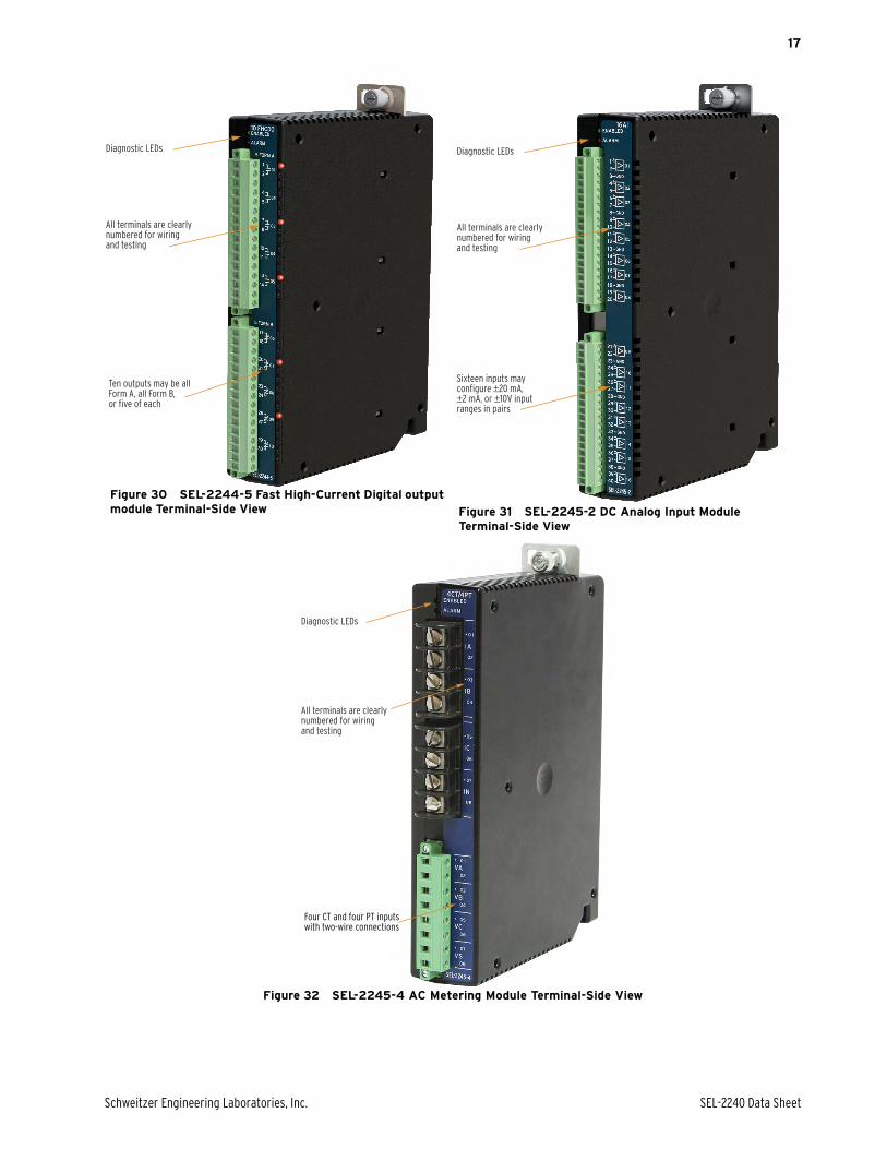
Figure 30 SEL-2244-5 Fast High-Current Digital output module Terminal-Side View Figure 31 SEL-2245-2 DC Analog Input Module
Terminal-Side View
Figure 32 SEL-2245-4 AC Metering Module Terminal-Side View
Diagnostic LEDs
All terminals are clearlynumbered for wiringand testing
Ten outputs may be all Form A, all Form B, or five of each
Diagnostic LEDs
All terminals are clearlynumbered for wiringand testing
Sixteen inputs may configure ±20 mA, ±2 mA, or ±10V input ranges in pairs
Diagnostic LEDs
All terminals are clearlynumbered for wiringand testing
Four CT and four PT inputs with two-wire connections

SEL-2240 Data Sheet Schweitzer Engineering Laboratories, Inc.
18
Guideform SpecificationThe microprocessor-based system shall operate simultaneously on multiple serial and Ethernet communicationsnetworks. It shall provide a combination of functions that include digital input and digital output support, deterministiclogic processing, automatic transmission of outgoing messages and processing of responses, data scaling, dataaggregation, simultaneous collection of data from multiple server devices, and simultaneous data access for multipleclient (master) devices. The system shall provide IEC 61850 GOOSE, EtherCAT, Modbus RTU and Modbus TCPclient/server, LG 8979 client/server, SES-92 server, IEC 60870-5 101/104 server, DNP3 Level 3 serial, and DNP3Level 3 LAN/WAN client/server protocols. Specific operational and functional requirements are as follows:
➤ Digital Inputs Sequential Events. The systemshall maintain a user-configurable record of digitalinput operations on the EtherCAT network that isaccurate to 1 ms.
➤ DC Analog Inputs. The system can include asmany as sixteen DC analog input modules. Inputranges are ±20 mA, ±2 mA, and ±10 V.
➤ AC Analog Inputs. The system can include asmany as 16 CT/PT analog input modules. Inputranges are 0–22 A for CT inputs and 5–400 V forPT inputs.
➤ Intelligent and Secure Components. All elec-tronic equipment shall continuously self-test andreport internal errors. The system shall have ahardwire contact indicating system health.
➤ IEC 61131-3 Programming. The system shallinclude an integrated IEC 61131-3 programmingenvironment, with the ability to monitor and con-trol every connected EtherCAT I/O module, pro-tective relay, and other serial or Ethernet-basedintelligent electronic devices (IED) continuously.The IEC 61131-3 programming environment shallbe integrated in one software package with thecommunications protocol mapping environment.
➤ Role-Based Security. The system shall incorpo-rate independent user-based security with strongpasswords, role-based accounts, and settableaccount expirations dates. The system shall pro-vide a mechanism to map security related systemtags into SCADA reports.
➤ Central Authentication. The system shall useLightweight Directory Access Protocol (LDAP) toprovide central user account authentication.
➤ Selectable Processing Interval and Solve Order.The system shall include a method to configure thedeterministic processing interval for protocol com-munications and custom logic. The system shallalso include a method to configure the processingsequence of software tasks.
➤ Redundant Power Supply Operation. The sys-tem shall allow the use of two power supply mod-ules that continuously share load. If the incomingpower for one module becomes unavailable, theremaining power supply shall have sufficientcapacity to accommodate an entire node.
➤ High-Speed Peer-to-Peer Communication. Thesystem shall use MIRRORED BITS® communica-tions and IEC 61850 GOOSE protocol to transmit
and receive high-speed digital data to/from IEDs tocreate custom protection and control schemes.IEC 61850 GOOSE shall be an available option forthe system.
➤ IEC 61850. The information processor shall havean option to support IEC 61850 GOOSE transmitand receive messaging. There shall also be anoption to support IEC 61850 MMS client for poll-ing data sets and reports from IEDs.
➤ Deterministic Ethernet Fieldbus. The systemshall use EtherCAT protocol to operate a determin-istic, Ethernet-based fieldbus network for con-nected I/O modules.
➤ Web-Based HMI. The system shall have anoptional web-based HMI that has complete accessto all system tags available.
➤ Serial Communications Ports. The system shallhave four serial ports that shall be software config-urable for EIA-232 or EIA-485 communicationsmodes. Each serial port connector shall have anavailable demodulated IRIG-B time-synchroniza-tion signal.
➤ Ethernet Communications Ports. The CPU mod-ule for the system shall have two Ethernet portsthat can operate simultaneously on different net-works through independent MAC addresses.
➤ Alarm Output. There shall be an alarm contactoutput to signal internal errors and malfunctions.The alarm contact shall be programmable so thatthe alarm conditions that activate the output caninclude additional conditions.
➤ Environmental Testing. All system modules shallbe tested to IEEE 1613-2003 for communicationsand networking equipment in electric power sub-stations. The system modules shall also be tested tothe same standards as those used for protectiverelays.
➤ Synchrophasors. The system CPU shall be capa-ble of receiving synchronized phasor measurementdata via the IEEE C37.118 protocol on all serialand Ethernet ports at rates as fast as 60 messagesper second. Additionally, as many as 14 phasormeasurements may be served to a master at rates asfast as 60 messages per second.
➤ Retained Memory. The system CPU shall havenonvolatile memory available for user-programma-ble retained variables.
Schweitzer Engineering Laboratories, Inc. SEL-2240 Data Sheet
19
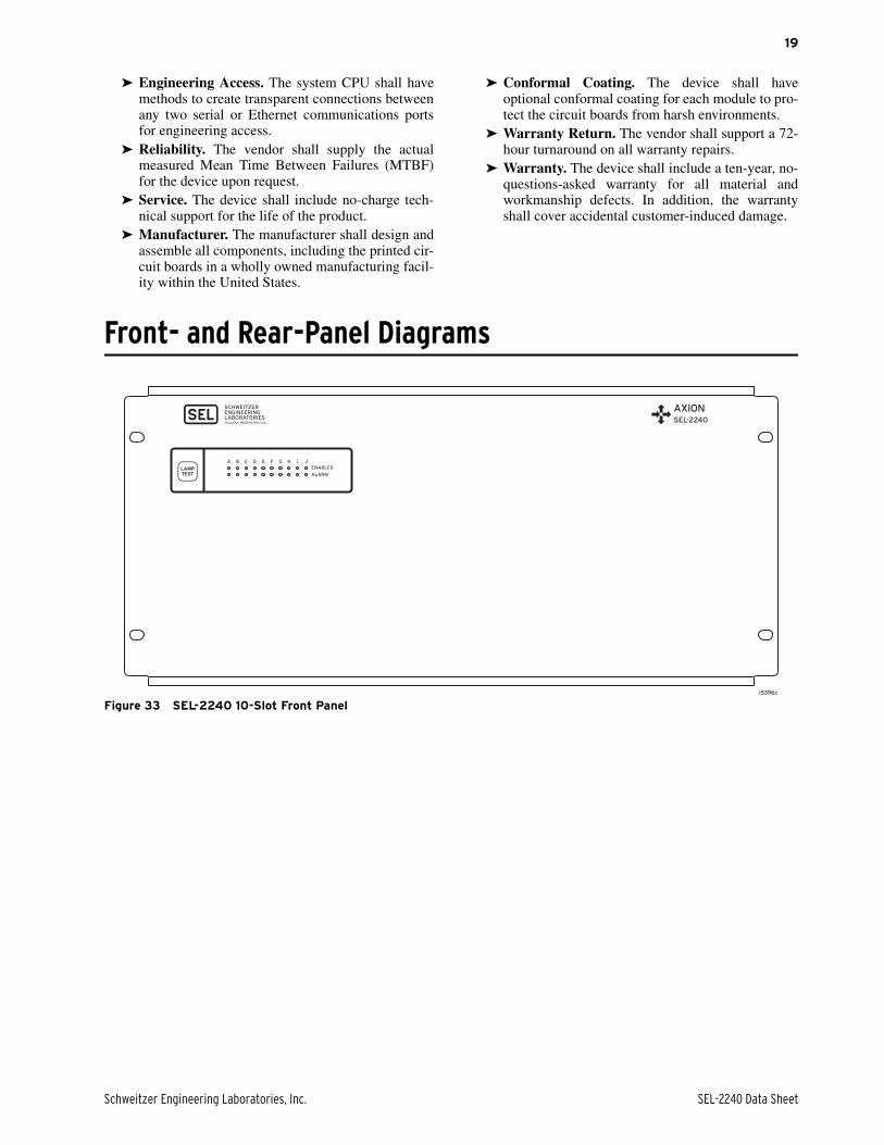
➤ Engineering Access. The system CPU shall havemethods to create transparent connections betweenany two serial or Ethernet communications portsfor engineering access.
➤ Reliability. The vendor shall supply the actualmeasured Mean Time Between Failures (MTBF)for the device upon request.
➤ Service. The device shall include no-charge tech-nical support for the life of the product.
➤ Manufacturer. The manufacturer shall design andassemble all components, including the printed cir-cuit boards in a wholly owned manufacturing facil-ity within the United States.
➤ Conformal Coating. The device shall haveoptional conformal coating for each module to pro-tect the circuit boards from harsh environments.
➤ Warranty Return. The vendor shall support a 72-hour turnaround on all warranty repairs.
➤ Warranty. The device shall include a ten-year, no-questions-asked warranty for all material andworkmanship defects. In addition, the warrantyshall cover accidental customer-induced damage.
Front- and Rear-Panel Diagrams
Figure 33 SEL-2240 10-Slot Front Paneli5396c
SEL-2240 Data Sheet Schweitzer Engineering Laboratories, Inc.
20
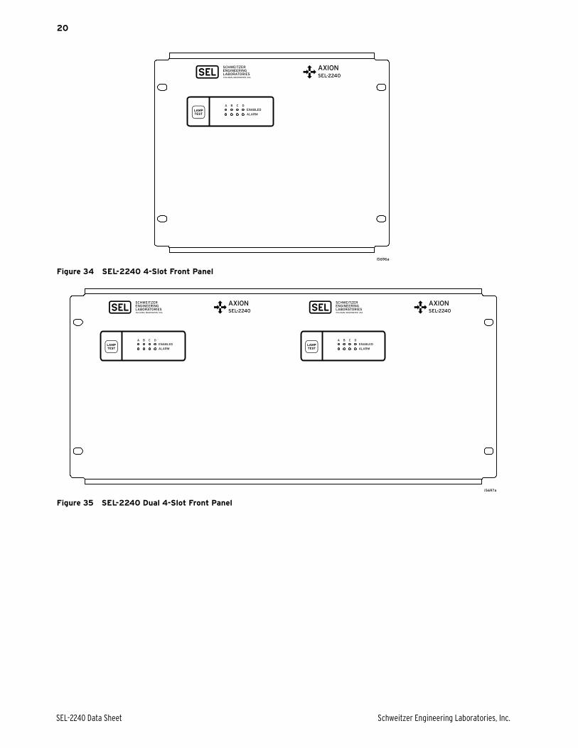
Figure 34 SEL-2240 4-Slot Front Panel
Figure 35 SEL-2240 Dual 4-Slot Front Panel
Schweitzer Engineering Laboratories, Inc. SEL-2240 Data Sheet
21
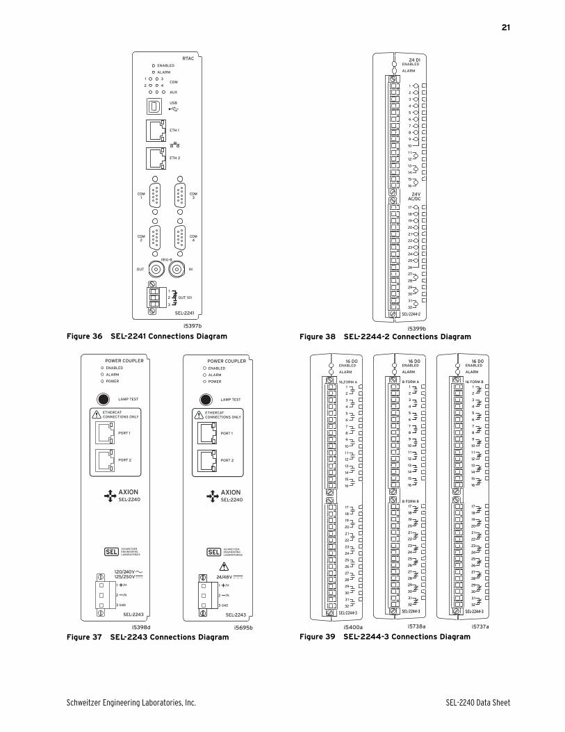
Figure 36 SEL-2241 Connections Diagram
Figure 37 SEL-2243 Connections Diagram
Figure 38 SEL-2244-2 Connections Diagram
Figure 39 SEL-2244-3 Connections Diagram
i5397b
SEL-2241
ALARM
OUT 101
3
4
1
2COM
AUX
USB
ENABLED
ETH 1
ETH 2
INOUT
IRIG-B
COM1
COM2
COM3
COM4
RTAC
1
2
3
i5398d i5695b
i5399b
1
17
18
19
20
21
22
23
24
25
26
27
28
29
30
31
32
2
3
4
5
6
7
8
9
10
1 1
12
13
14
15
16
24 DIENABLED
ALARM
24VAC/DC
i5400a
32
16
1
17
18
19
20
21
22
23
24
25
26
27
28
29
30
31
2
3
4
5
6
7
8
9
10
1 1
12
13
14
15
16 D0ENABLED
ALARM
16 FORM A
SEL-2240 Data Sheet Schweitzer Engineering Laboratories, Inc.
22
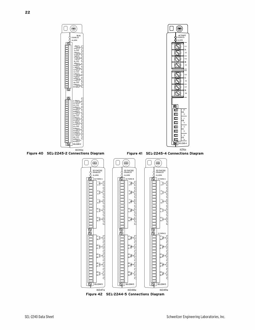
Figure 40 SEL-2245-2 Connections Diagram Figure 41 SEL-2245-4 Connections Diagram
Figure 42 SEL-2244-5 Connections Diagram
i6316a
Schweitzer Engineering Laboratories, Inc. SEL-2240 Data Sheet
23
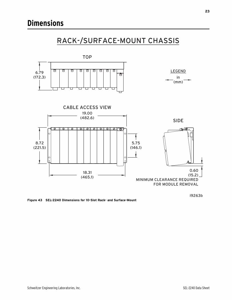
Dimensions
Figure 43 SEL-2240 Dimensions for 10-Slot Rack- and Surface-Mount
SEL-2240 Data Sheet Schweitzer Engineering Laboratories, Inc.
24
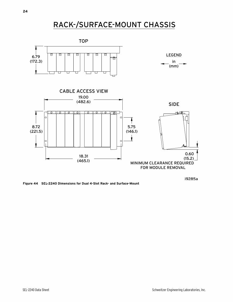
Figure 44 SEL-2240 Dimensions for Dual 4-Slot Rack- and Surface-Mount

Schweitzer Engineering Laboratories, Inc. SEL-2240 Data Sheet
25
Figure 45 SEL-2240 Dimensions for 4-Slot Rack- and Surface-Mount

SEL-2240 Data Sheet Schweitzer Engineering Laboratories, Inc.
26
Specifications
General
Operating Temperature Range
–40° to +85°C (–40° to +185°F)Note: Not applicable to UL applications.
Operating Environment
Pollution Degree: 2
Overvoltage Category: II
Relative Humidity: 5–95%, noncondensing
Maximum Altitude: 2000 m
Dimensions
Refer to Section 2: Installation in the SEL-2240 Instruction Manual for dimensions.
Weight (Fully Populated Node)
16 lbs
CPU
Processing and Memory
Processor Speed: 533 MHz
Memory: 512 MB DDR2 ECC RAM
Storage: 4 GB (2 GB reserved)
Security FeaturesAccount Management: User Accounts
User RolesLDAP Central AuthenticationStrong PasswordsInactive Account Logouts
Intrusion Detection: Access/Audit LogsAlarm LEDAlarm Contact
Encrypted Communication: SSL/TLS, SSH, HTTPS
Automation Features
Protocols
Client: DNP3 Serial, DNP3 LAN/WAN, Modbus RTU, Modbus TCP, SEL ASCII, SEL Fast Messaging, LG 8979, IEEE 37.118, IEC 61850 MMS
Server: DNP3 Serial, DNP3 LAN/WAN, Modbus RTU, Modbus TCP, SEL Fast Messaging, LG 8979, SES-92, IEC 60870-5 101/104
Peer-to-Peer: SEL MIRRORED BITS Communications, IEC 61850 GOOSE, Network Global Variables (NGVL)
Fieldbus: EtherCAT Client (in RTAC), EtherCAT Server (I/O modules)
Engineering Access
Modes: SEL Interleaved, Direct
Port Server: Map Serial Ports to IP Ports
Secure Web Server: Diagnostic and Communications Data
Time-Code Input (Modulated IRIG-B)Input Impedance: 2 k
Accuracy: 500 µs
Time-Code Input (Demodulated IRIG-B)On (1) State: Vih > 2.2 V
Off (0) State: Vil < 0.8 V
Input Impedance: 2 k
Accuracy: 500 ns
Time-Code Output (IRIG-B)On (1) State: Voh > 2.4 V
Off (0) State: Vol < 0.8 V
Load: 50
Network Time Protocol (NTP) ModesNTP Client: Up to three configurable servers
NTP Server
Communications Ports (SEL-2241 RTAC)
Ethernet Ports (To Backplane)
Ports: 1
Data Rate: Automatic
Protocols: Dedicated EtherCAT port
Ethernet Ports (Terminal Side)
Ports: 2
Data Rate: 10 or 100 Mbps
Connector: RJ45 Female or LC Fiber (100 Mbps only)
Fiber-Optic Ports
Class 1 LASER/LED
Wavelength: 1300 nm
Optical Connector Type: LC
Fiber Type: Multimode
Link Budget: 11 dB
Min. TX Power: –20 dBm
Min. RX Sensitivity: –31 dBm
Fiber Size: 50–200 µm
Approximate Range: 5 Km
Data Rate: 100 Mb
Typical Fiber Attenuation:
–2 dB/Km
Serial Ports
Ports: 4
Types: EIA-232/EIA-485 (software selectable)
Data Rate: 300 to 115200 bps
Connector: DB-9 Female
Time Synchronization: IRIG-B
Power: +5 Vdc power on Pin 1 (500 mA maximum)
USB Ports
Device Ports: 1 Type B

Schweitzer Engineering Laboratories, Inc. SEL-2240 Data Sheet
27
Output (SEL-2241 RTAC)Mechanical Durability: 10 M no load operations
DC Output Ratings
Rated Operational Voltage: 250 Vdc
Rated Voltage Range: 19.2–275 Vdc
Rated Insulation Voltage: 300 Vdc
Make: 30 A @ 250 Vdc per IEEE C37.90
Continuous Carry: 6 A @ 70°C; 4 A @ 85°C
Thermal: 50 A for 1 s
Contact Protection: 360 Vdc, 40 J MOV
Operating Time (coil energization to contact closure, resistive load): Pickup/Dropout time 8 ms typical
Breaking Capacity(10,000 operations) per IEC 60255-0-20:1974:
24 Vdc 0.75 A L/R = 40 ms48 Vdc 0.50 A L/R = 40 ms125 Vdc 0.30 A L/R = 40 ms250 Vdc 0.20 A L/R = 40 ms
Cyclic Capacity (2.5 cycles/second) per IEC 60255-0-20:1974:
24 Vdc 0.75 A L/R = 40 ms48 Vdc 0.50 A L/R = 40 ms125 Vdc 0.30 A L/R = 40 ms250 Vdc 0.20 A L/R = 40 ms
AC Output Ratings
Rated Operational Voltage: 240 Vac
Rated Insulation Voltage: 300 Vac
Utilization Category: AC-15 (control of electromagnetic loads > 72 VA)
Contact Rating Designation:
B300 (B = 5 A, 300 = rated insulation voltage)
Contact Protection: 270 Vac, 40 J
Continuous Carry: 3 A @ 120 Vac1.5 A @ 240 Vac
Conventional EnclosedThermal Current (Ithe)Rating: 5 A
Rated Frequency: 50/60 ±5 Hz
Operating Time (coil energization to contact closure, resistive load): Pickup/Dropout time < 8 ms typical
Electrical Durability Make VA Rating: 3600 VA, cosø = 0.3
Electrical Durability Break VA Rating: 360 VA, cosø = 0.3
Power Coupler (SEL-2243)
EtherCAT Ports
Ports: 2
Data Rate: Automatic
Connector: RJ45 Female or LC Fiber
Protocols: Dedicated EtherCAT
Fiber-Optic Ports
Class 1 LASER/LED
Wavelength: 1300 nm
Optical Connector Type: LC
Fiber Type: Multimode
Link Budget: 11 dB
Min. TX Power: –20 dBm
Min. RX Sensitivity: –31 dBm
Fiber Size: 50–200 µm
Approximate Range: 5 Km
Data Rate: 100 Mb
Typical Fiber Attenuation:
–2 dB/Km
Power Supply
AC Input Voltage (High-Voltage Model)
Rated Supply Voltage: 120/240 Vac, 50/60 Hz
Input Voltage Range: 85–264 Vac, 40–70 Hz
DC Input Voltage (High-Voltage Model)
Rated Supply Voltage: 125/250 Vdc
Input Voltage Range: 85–300 Vdc
DC Input Voltage (Low-Voltage Model)
Rated Supply Voltage: 24/48 Vdc
Input Voltage Range: 19.1–57.6 Vdc polarity dependent
Power Consumption
Maximum AC Burden: 160 VA
Maximum DC Burden: 80 W
Interruptions: 30 ms @ 24 Vdc130 ms @ 48 Vdc50 ms @ 125 Vac/Vdc100 ms @ 250 Vac/Vdc
Max Inrush: 15 A
Isolation: 3100 Vdc
Redundant Installation
Each node may have one or two SEL-2243 modules installed. When two are used, they operate in load sharing mode.
Optoisolated Control Inputs (SEL-2244-2)When Used With DC Control Signals:
250 Vdc ON for 200–275 Vdc OFF below 150 Vdc
220 Vdc ON for 176–242 Vdc OFF below 132 Vdc
125 Vdc ON for 100–135.5 Vdc OFF below 75 Vdc
110 Vdc ON for 88–121 Vdc OFF below 66 Vdc
48 Vdc ON for 38.4–52.8 Vdc OFF below 28.8 Vdc
24 Vdc ON for 15–30 Vdc OFF for < 10 Vdc
When Used With AC Control Signals:
250 Vdc ON for 170.6–300 Vac OFF below 106 Vac
220 Vdc ON for 150.3–264 Vac OFF below 93.2 Vac
125 Vdc ON for 85–150 Vac OFF below 53 Vac
110 Vdc ON for 75.1–132 Vac OFF below 46.6 Vac
48 Vdc ON for 32.8–60 Vac OFF below 20.3 Vac
24 Vdc ON for 14–27 Vac OFF for < 5 Vac
Current Draw at Nominal DC Voltage: 2–4 mA (Except for 24 V, 8 mA)
Rated Insulation Voltage: 300 Vac
Rated Impulse Withstand Voltage (Uimp): 4000 V
SEL-2240 Data Sheet Schweitzer Engineering Laboratories, Inc.
28
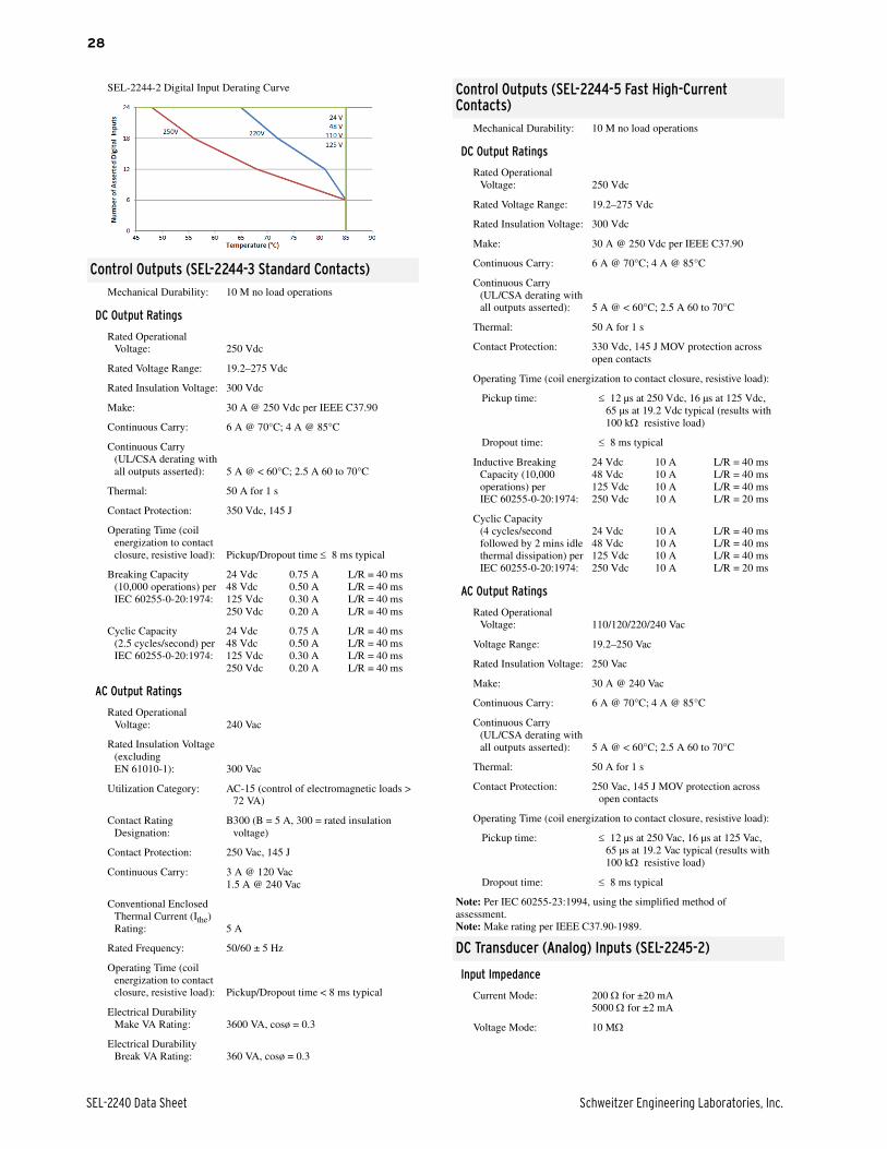
SEL-2244-2 Digital Input Derating Curve
Control Outputs (SEL-2244-3 Standard Contacts)Mechanical Durability: 10 M no load operations
DC Output Ratings
Rated Operational Voltage: 250 Vdc
Rated Voltage Range: 19.2–275 Vdc
Rated Insulation Voltage: 300 Vdc
Make: 30 A @ 250 Vdc per IEEE C37.90
Continuous Carry: 6 A @ 70°C; 4 A @ 85°C
Continuous Carry (UL/CSA derating with all outputs asserted): 5 A @ < 60°C; 2.5 A 60 to 70°C
Thermal: 50 A for 1 s
Contact Protection: 350 Vdc, 145 J
Operating Time (coil energization to contact closure, resistive load): Pickup/Dropout time 8 ms typical
Breaking Capacity (10,000 operations) per IEC 60255-0-20:1974:
24 Vdc 0.75 A L/R = 40 ms48 Vdc 0.50 A L/R = 40 ms125 Vdc 0.30 A L/R = 40 ms250 Vdc 0.20 A L/R = 40 ms
Cyclic Capacity (2.5 cycles/second) per IEC 60255-0-20:1974:
24 Vdc 0.75 A L/R = 40 ms48 Vdc 0.50 A L/R = 40 ms125 Vdc 0.30 A L/R = 40 ms250 Vdc 0.20 A L/R = 40 ms
AC Output Ratings
Rated Operational Voltage: 240 Vac
Rated Insulation Voltage (excluding EN 61010-1): 300 Vac
Utilization Category: AC-15 (control of electromagnetic loads > 72 VA)
Contact Rating Designation:
B300 (B = 5 A, 300 = rated insulation voltage)
Contact Protection: 250 Vac, 145 J
Continuous Carry: 3 A @ 120 Vac1.5 A @ 240 Vac
Conventional Enclosed Thermal Current (Ithe) Rating: 5 A
Rated Frequency: 50/60 ± 5 Hz
Operating Time (coil energization to contact closure, resistive load): Pickup/Dropout time < 8 ms typical
Electrical Durability Make VA Rating: 3600 VA, cosø = 0.3
Electrical Durability Break VA Rating: 360 VA, cosø = 0.3
Control Outputs (SEL-2244-5 Fast High-Current Contacts)
Mechanical Durability: 10 M no load operations
DC Output Ratings
Rated Operational Voltage: 250 Vdc
Rated Voltage Range: 19.2–275 Vdc
Rated Insulation Voltage: 300 Vdc
Make: 30 A @ 250 Vdc per IEEE C37.90
Continuous Carry: 6 A @ 70°C; 4 A @ 85°C
Continuous Carry (UL/CSA derating with all outputs asserted): 5 A @ < 60°C; 2.5 A 60 to 70°C
Thermal: 50 A for 1 s
Contact Protection: 330 Vdc, 145 J MOV protection across open contacts
Operating Time (coil energization to contact closure, resistive load):
Pickup time: 12 µs at 250 Vdc, 16 µs at 125 Vdc, 65 µs at 19.2 Vdc typical (results with 100 k resistive load)
Dropout time: 8 ms typical
Inductive Breaking Capacity (10,000 operations) per IEC 60255-0-20:1974:
24 Vdc 10 A L/R = 40 ms48 Vdc 10 A L/R = 40 ms125 Vdc 10 A L/R = 40 ms250 Vdc 10 A L/R = 20 ms
Cyclic Capacity (4 cycles/second followed by 2 mins idle thermal dissipation) per IEC 60255-0-20:1974:
24 Vdc 10 A L/R = 40 ms48 Vdc 10 A L/R = 40 ms125 Vdc 10 A L/R = 40 ms250 Vdc 10 A L/R = 20 ms
AC Output Ratings
Rated Operational Voltage: 110/120/220/240 Vac
Voltage Range: 19.2–250 Vac
Rated Insulation Voltage: 250 Vac
Make: 30 A @ 240 Vac
Continuous Carry: 6 A @ 70°C; 4 A @ 85°C
Continuous Carry (UL/CSA derating with all outputs asserted): 5 A @ < 60°C; 2.5 A 60 to 70°C
Thermal: 50 A for 1 s
Contact Protection: 250 Vac, 145 J MOV protection across open contacts
Operating Time (coil energization to contact closure, resistive load):
Pickup time: 12 µs at 250 Vac, 16 µs at 125 Vac, 65 µs at 19.2 Vac typical (results with 100 k resistive load)
Dropout time: 8 ms typical
Note: Per IEC 60255-23:1994, using the simplified method ofassessment.Note: Make rating per IEEE C37.90-1989.
DC Transducer (Analog) Inputs (SEL-2245-2)
Input Impedance
Current Mode: 200 for ±20 mA5000 for ±2 mA
Voltage Mode: 10 M
Schweitzer Engineering Laboratories, Inc. SEL-2240 Data Sheet
29
Input Range (Maximum): ±20 mA (transducers: 4–20 mA or 0–20 mA typical)
±2 mA (transducers: 0–1 mA or 0–2 mA typical)
±10 V (transducers: 0–5 V or 0–10 V typical)
Sampling Rate 1 ksps
Anti Alias Filter
Corner Frequency: 300–400 Hz, 330 Hz Typical
Rolloff: 20 dBV per decade
Digital Filter
Corner Frequency: Filter A: < 20 Hz, 16 Hz typicalFilter B: < 20 Hz, 10 Hz typical
50 Hz Rejection: Filter A: > 30 dBV, 31 dBV typicalFilter B: > 50 dBV, 54 dBV typical
60 Hz Rejection: Filter A: > 30 dBV, 68 dBV typicalFilter B: > 50 dBV, 76 dBV typical
Step Response
No Filter: < 3 ms (10–90% response typical)
Filter A: < 50 ms (10–90% response)
Filter B: < 200 ms (10–90% response)
Common Mode Range
±35 Vdc between separate inputs±250 Vdc all inputs to chassis
Isolation
500 Vac between inputs2000 Vac all inputs to chassis
Accuracy at 25°C
ADC: 16 bit 0.05% of full scale
Inputs: 0.25% of full scale (voltage mode)0.5% of full scale (current mode)
Accuracy Variation With Temperature
Inputs: ±0.015% per °C of full scale (±20 mA, ±2 mA, or ±10 V)
ADC: ±0.004% per °C
AC Metering Inputs (SEL-2245-4)
Frequency: 50/60 Hz
Range: 45–65 Hz
Typical Accuracy: ±0.005 Hz above 20 V
Worst Case Accuracy: ±0.01 Hz above 20 V
Phase Rotation: ABC, ACB
Input Configuration: 3-Wire Delta, 4-Wire Wye
Update Interval
Fundamental Metering: 200 Hz
RMS Metering: 5 Hz
Current Inputs Phase and Neutral
INOM: 5 A
Measurement Range: 0.050–22 A Continuous 22–100 A Symmetrical for 25 s
Thermal Withstand Limit: 500 A for 1 s
Typical Accuracy: ±1% Fundamental@ fNOM±0.1% RMS@ fNOM
Worst Case Accuracy: ±2% ± 0.005 A Fundamental/RMS
Angle
Range: ±180°
Typical Accuracy: ±0.5° Fundamental @ fNOM
Worst Case Accuracy: ±2% @ fNOM
Burden: < 0.1 VA @ INOM
Voltage Inputs
VNOM: 300 V
Measurement Range: 5–400 L-N, 9–693 L-L Vac Fundamental/RMS
5–300 L-N, 9–520 L-L Vac Fundamental/RMS (UL)
Maximum: 600 L-N, 1039 L-L Vac Fundamental/RMS for 10 s
Typical Accuracy: ±1% Fundamental@ fNOM±0.1% RMS@ fNOM
Worst Case Accuracy: ±3% Fundamental@ fNOM±3% RMS plus ±0.05 V
Angle
Range: ±180°
Typical Accuracy: ±0.3° @ fNOM
Worst Case Accuracy: ±2° @ fNOM
Burden: < 0.1 VA
Sequence Components
Values: I0, I1, I2, V0, V1, V2
Typical Accuracy
Magnitude: ±5% @ fNOM
Angle: ±2° @ fNOM
Power and Power Factor (Per Phase and Three-Phase)
Typical Accuracy: ±0.1% @ fNOM
Synchrophasor
Accuracy: Level 1 as specified by IEEE C37.118
Measurements: Software selectable
Voltage: VA, VB, VC, VS
Current: IA, IB, IC, IN
Positive-Sequence: V1, I1
Periodic: Frequency and df/dt
Processing Rate: 120 Hz
Triggered Waveform Recording
Sampling Rates: 1, 2, 3, 8, 24 kHz software selectable
Record Duration: 0.1 second increments from 0.5 s to specified maximum for each sample rate.
Maximum Record Duration:
6 s at 24 kHz18 s at 8 kHz36 s at 4 kHz72 s at 2 kHz144 s at 1 kHz
Record Pretrigger: 0.05 s minimum up to a maximum of (record length –0.05) s
Waveform File Format: COMTRADE (IEEE C37.111-1999 compliant)

SEL-2240 Data Sheet Schweitzer Engineering Laboratories, Inc.
30
Notes

Schweitzer Engineering Laboratories, Inc. SEL-2240 Data Sheet
31

32
© 2011–2013 by Schweitzer Engineering Laboratories, Inc. All rights reserved.
All brand or product names appearing in this document are the trademark or registeredtrademark of their respective holders. No SEL trademarks may be used without writtenpermission. SEL products appearing in this document may be covered by US and Foreignpatents.
Schweitzer Engineering Laboratories, Inc. reserves all rights and benefits afforded underfederal and international copyright and patent laws in its products, including without lim-itation software, firmware, and documentation.
The information in this document is provided for informational use only and is subject tochange without notice. Schweitzer Engineering Laboratories, Inc. has approved only theEnglish language document.
This product is covered by the standard SEL 10-year warranty. For warranty details, visitwww.selinc.com or contact your customer service representative.
EtherCAT® is registered trademark and patented technology, licensed by Beckhoff Auto-mation GmbH, Germany.
*PDS2240-01*
SCHWEITZER ENGINEERING LABORATORIES2350 NE Hopkins Court • Pullman, WA 99163-5603 USA
Phone: +1.509.332.1890 • Fax: +1.509.332.7990
Internet: www.selinc.com • E-mail: [email protected]
SEL-2240 Data Sheet Date Code 20130827