2.3 design guideline water supply booster pump station · design guideline water supply booster...
TRANSCRIPT

2.3
Design Guideline
Water Supply Booster Pump Station

2.3 Water Supply Booster Pump Station - Design Guideline
Date Published: Page 2 of 13 Reference Number: DOC13/71292
---- Uncontrolled document when printed ----
Title 2.3 Water Supply Booster Pump Station - Design Guideline
System
Reference Number DOC13/71292
Approved By
Date Approved
Next review date
Note: With each edit to this document, the following must be completed. Also if a
document is being reviewed and there are no changes, it should be noted that the review
was undertaken and the next review date updated.
Details of Review/Changes
Date Description Modified By Approved By
Feb 2010 Original draft issue Claire Speedy Steven Nash
Mar 2010 Revised draft issue Steven Nash Bruce
Anderson
Sept 2010 Revised format Jeff Block
June 2011 Revised format Adam
Glasson
Michael Welk
Sept 2012 New numbering and front page design Adam
Glasson
Michael Welk
June 2013 Added risk section Adam
Glasson
Michael Welk
Mar 2016 Perimeter fence amended Michael Welk Michael Welk
Mar 2016 Added new GVW logo and AS/NZS 4020
requirement
Adam
Glasson
Michael Welk
May 2016 Reformatted to new GVW style guide Kirsten
Hogan
2.3 Water Supply Booster Pump Station - Design Guideline
Date Published: Page 3 of 13 Reference Number: DOC13/71292
---- Uncontrolled document when printed ----
Table of Contents
Description: ....................................................................................................................... 4
Objective: .......................................................................................................................... 4
Risk: .................................................................................................................................. 4
Reference Documents: ..................................................................................................... 4
Component Description: ................................................................................................... 5
1. Pump Station Site ................................................................................................... 5
2. Electricity Supply .................................................................................................... 5
3. Switchboard ............................................................................................................ 5
4. Perimeter Fence ..................................................................................................... 6
5. Pumps..................................................................................................................... 6
6. Pump Controls ........................................................................................................ 7
7. Pipework ................................................................................................................. 7
8. Electromagnetic Flow Meter ................................................................................... 7
9. Standard Drawings and Site Photos ...................................................................... 8
Schematic Plan: ............................................................................................................... 9
Figure 1 – Avenel Park Estate Site Layout Plan ............................................................ 10
Figure 3 and 4 – Pump Configurations – Avenel Park Estate ....................................... 12
2.3 Water Supply Booster Pump Station - Design Guideline
Date Published: Page 4 of 13 Reference Number: DOC13/71292
---- Uncontrolled document when printed ----
Description:
The water supply booster pump station is a component of the reticulation system and will
pump to an elevated water supply storage tank upon demand. The operation of the pump
will be governed by a low water level signal from the tank.
Objective:
The objective of the water supply booster pump station is to provide a water supply that
meets the customer demands for reliability of supply and flow.
Risk:
This Guideline may identify some risks and provides guidance in mitigating these risks.
However a further site specific assessment and/or HAZOP are required to address other
risks.
All materials in contact with potable water must comply with AS/NZS 4020 and utilise
WSAA National Codes and standards where applicable.
Reference Documents:
AS/NZS 4020: Testing of products for use in contact with drinking water
WSAA – MRWA – Water Supply Code of Australia
GVW Supplement to the WSAA – MRWA – Water Supply Code of Australia
GVW Product Manual
GVW Development and Construction Manual
Design Manual – Water Storage Tank (To be prepared)
GVW General Electrical Specification
GVW Booster Pump Station Specific Electrical/Requirements
GVW Building Aesthetics – Design Manual
Design Guideline: 1.5 Security Fencing

2.3 Water Supply Booster Pump Station - Design Guideline
Date Published: Page 5 of 13 Reference Number: DOC13/71292
---- Uncontrolled document when printed ----
Component Description:
1. Pump Station Site
The pump station site is to be located within a reserve in favour of the Goulburn
Valley Region Water Corporation.
The pump site is to be selected where a sufficient water supply is provided at peak
periods for the pump to operate (water pressure and flow). Advice is to be sought
from Goulburn Valley Water’s Planning and Project Development Section.
The site is not to be encumbered by existing or proposed overhead power lines
and is to provide satisfactory coverage for monitoring and control via SCADA.
The site must be accessible by vehicles by means of an all weather road. The
minimum width of the access is 3 metre wide and sufficient space is to be
provided for a light truck vehicle to turn and for at least 1 parking space.
The surrounding area of the pump station site is to be covered with a minimum of
100mm compacted crushed rock or similar approved material to provide an all
weather access to the site.
The layout of the pump station must ensure that the available space for
maintenance purposes is maximised. A minimum of 1 metre clearance between
all assets and the reserve title boundary must be achieved.
2. Electricity Supply
The capacity of the electricity supply system needs to be investigated to ensure
that there is an electricity supply capable of meeting pump station loading within
electricity supply regulations for both Amperage and Voltage.
If a development project, then the connection to the grid is to be arranged by the
consultant including the meeting of associated costs as part of the project. These
include:
Costs to hook into grid
Expected running costs of pump annually and life time
Pump wiring requirements,
Generator change over ability
All weather control box
3. Switchboard
The electrical cabinet and switchboard is to be in accordance with the GVW
Standard Specification for Switchboards. This is available upon request via email
GVW General Electrical Specification
GVW Booster Pump Station Specific Electrical/Requirements

2.3 Water Supply Booster Pump Station - Design Guideline
Date Published: Page 6 of 13 Reference Number: DOC13/71292
---- Uncontrolled document when printed ----
4. Perimeter Fence
The perimeter Fence shall comply with the Design Guideline: 1.5 Security Fencing
5. Pumps
All booster pump stations that boost water supply to an elevated water supply
storage tank are to equipped with 2 No. complete and identical pumpsets, (duty
and standby) and are to be rated to operate in an open weather environment.
The selection of the pump and the design of the inlet water main to the storage
tank should minimise the pressure spike to customers to 5 metres head, if there is
a single inlet/outlet pipeline to the tank. The preference is dedicated inlet and
outlet water mains.
The noise generated from the start, stop and running of the pumps is to be
considered and must comply with EPA requirements. If noise is an issue to
neighbouring properties, then sound attenuation measures, such as an enclosure
should be considered.
Pumps should be located adjacent to the access/parking area, so that there is
unrestricted access to pumps to allow lifting as required using a small GVW crane
truck.
Pumps and pipework are to be secured to a suitable concrete slab, which drains
surface water adequately.

2.3 Water Supply Booster Pump Station - Design Guideline
Date Published: Page 7 of 13 Reference Number: DOC13/71292
---- Uncontrolled document when printed ----
6. Pump Controls
The pumps are to operate on a duty call and duty stop set point from the storage
tank. There is to be a telemetry (radio) link between pumps station and storage
tank.
Cable is not to be used when the distance between the pumps and the tanks is
greater than 100m.
The pumps should have an automatic changeover between the duty and standby.
The preferred arrangement is for the water level in the storage tank to be relayed
to the pump station, which displays all information and is connected to SCADA.
7. Pipework
All pipework in the vicinity of the pumps is to be above ground and comprise
flanged or welded stainless steel or flanged DICL pipework.
Inlet and outlet pipes to be cast into the 100mm thick reinforced concrete slab.
All below ground pipe work within the pump station site must be DICL material.
8. Electromagnetic Flow Meter
A magnetic flow meter is to be installed on the discharge pipework from the
pumps and located above ground.
Installation must comply with the electromagnetic flow meter design guideline.
The discharge flow rate is to be displayed on the electrical cabinet and also linked
to SCADA, so that it can be viewed remotely.
2.3 Water Supply Booster Pump Station - Design Guideline
Date Published: Page 8 of 13 Reference Number: DOC13/71292
---- Uncontrolled document when printed ----
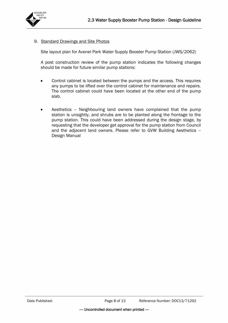
9. Standard Drawings and Site Photos
Site layout plan for Avenel Park Water Supply Booster Pump Station (JWS/2062)
A post construction review of the pump station indicates the following changes
should be made for future similar pump stations:
Control cabinet is located between the pumps and the access. This requires
any pumps to be lifted over the control cabinet for maintenance and repairs.
The control cabinet could have been located at the other end of the pump
slab.
Aesthetics – Neighbouring land owners have complained that the pump
station is unsightly, and shrubs are to be planted along the frontage to the
pump station. This could have been addressed during the design stage, by
requesting that the developer get approval for the pump station from Council
and the adjacent land owners. Please refer to GVW Building Aesthetics –
Design Manual

2.3 Water Supply Booster Pump Station - Design Guideline
Date Published: Page 9 of 13 Reference Number: DOC13/71292
---- Uncontrolled document when printed ----
Schematic Plan:

2.3 Water Supply Booster Pump Station - Design Guideline
Date Published: Page 10 of 13 Reference Number: DOC13/71292
---- Uncontrolled document when printed ----
Figure 1 – Avenel Park Estate Site Layout Plan
2.3 Water Supply Booster Pump Station - Design Guideline
Date Published: Page 11 of 13 Reference Number: DOC13/71292
---- Uncontrolled document when printed ----
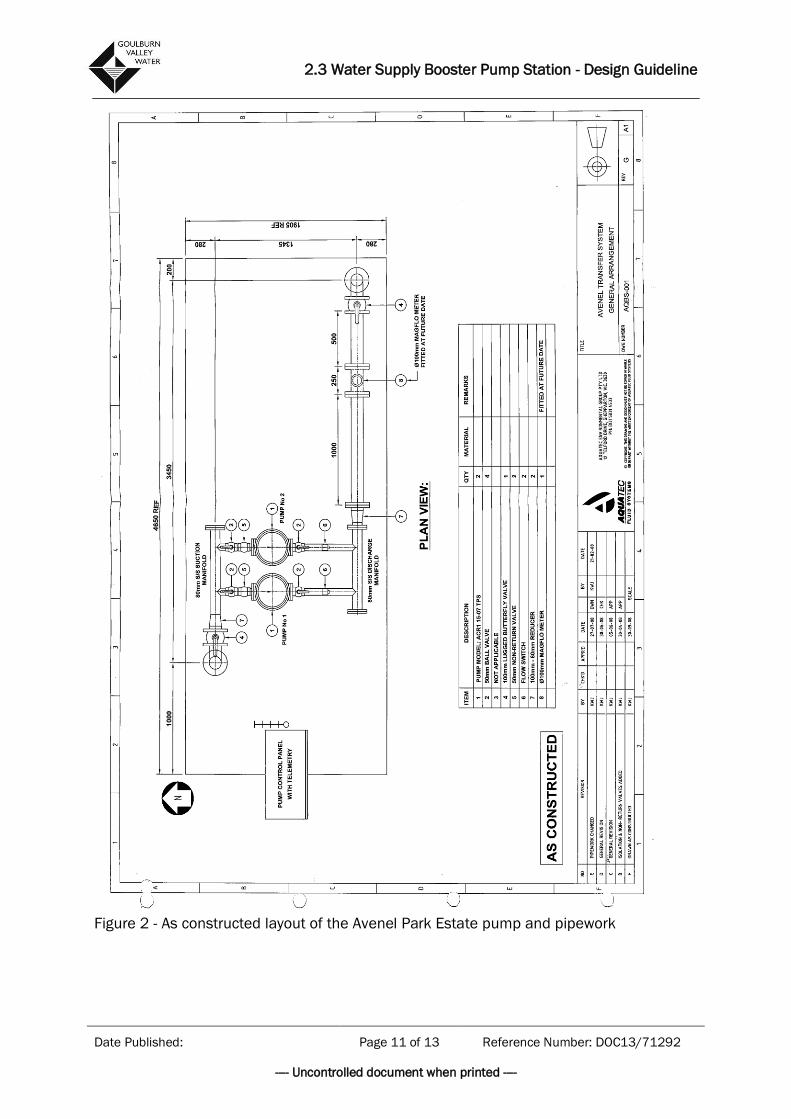
Figure 2 - As constructed layout of the Avenel Park Estate pump and pipework

2.3 Water Supply Booster Pump Station - Design Guideline
Date Published: Page 12 of 13 Reference Number: DOC13/71292
---- Uncontrolled document when printed ----
Figure 3 and 4 – Pump Configurations – Avenel Park Estate

2.3 Water Supply Booster Pump Station - Design Guideline
Date Published: Page 13 of 13 Reference Number: DOC13/71292
---- Uncontrolled document when printed ----
Figure 5