2.4 hydrocarbons from the direct liquefaction of solid fuels · · 2018-04-16coal has always been...
TRANSCRIPT

2.4.1 Introduction
Coal has always been used prevalently to generatepower and in the metallurgical industry. At times,however, the potential for using coal to manufactureliquid hydrocarbons for vehicle transportation has alsobeen considered.
The production of liquid hydrocarbons from coal(syncrude) can be carried out following two differenttechnological routes: indirect liquefaction, in otherwords, gasification to synthesis gas followed byFischer-Tropsch synthesis; direct liquefaction, that is,the transformation of coal into liquid hydrocarbons ina single stage using a hydrocracking process.
These technologies were both developed inGermany before the Second World War to counterthe oil embargo to which the country was subject atthe time, and to produce liquid hydrocarbons usingraw materials widely available in its territory.Starting from the post-war period, however, theavailability of large amounts of crude oil made thesetechnologies largely obsolete, except in South Africa(Sasol I and II processes), due to the country’sisolation from the international community caused byits apartheid regime (now overcome). From 1967, theyear of the first oil shock, these technologies wereagain taken into consideration, and for at least 20years intense R&D (Research and Development)work was carried out to identify new solutions able torender the production of syncrude from coalcompetitive with petroleum. In the case of directliquefaction, for example, important results wereobtained, making it possible to significantly improveperformance levels to the extent that processes ableto produce up to 5 bbl of oil per tonne of coal treatedbecame feasible.
Although various processes were also developed atthe demonstration plant level, falling oil prices from
1985 once again prevented this technology frombecoming established on a commercial scale, and ledto spending cuts affecting most research activities inthe sector. At the beginning of the third millennium,interest was reawakened by the construction of variousnew industrial plants for coal liquefaction in Asia(especially in China), that is economically emergingareas which possess enormous reserves of this rawmaterial. Further refinements of the technology andthe resulting decline in production costs, alongsidestrategic considerations, could render industrialinitiatives in this sector attractive, at least on a locallevel.
The role of coal in the international energyscenario
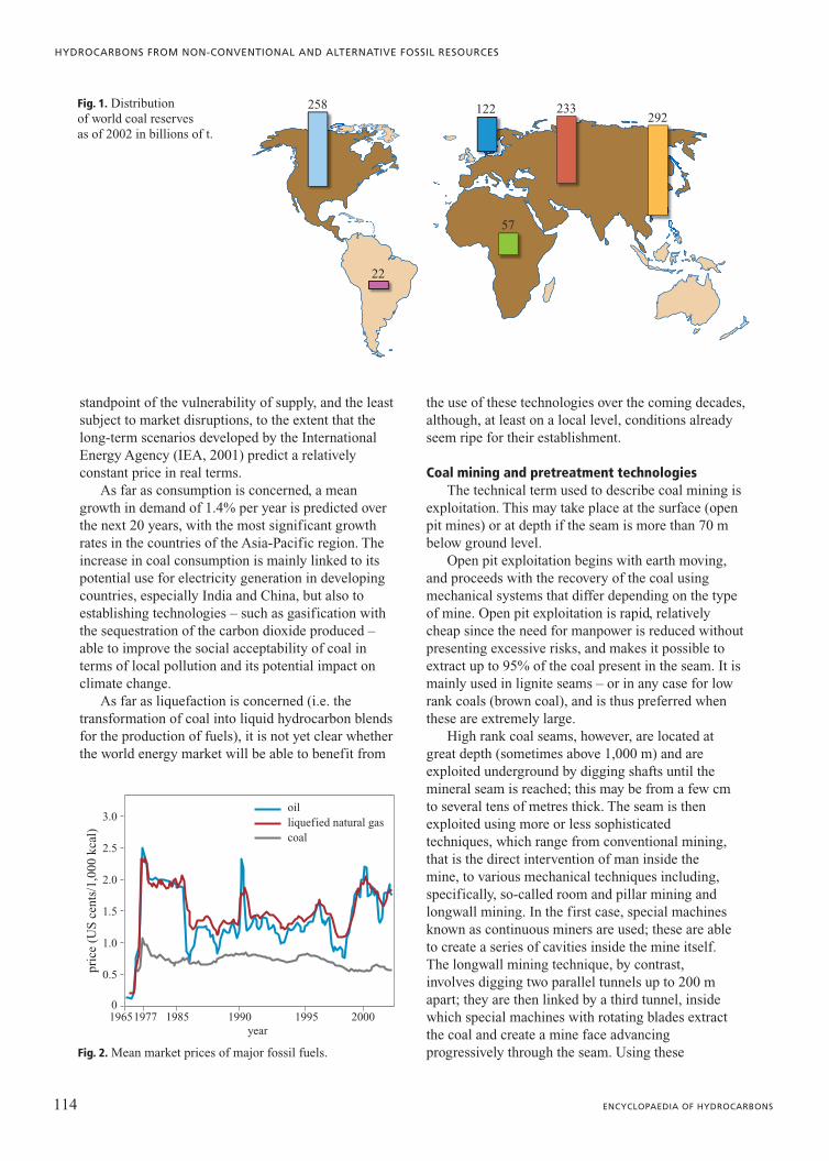
Coal is the most abundant fossil fuel on our planet.Proven reserves are estimated at about 1012 t,representing two-thirds of all existing fossil fuels. Atcurrent levels of consumption, this source could lastfor over 200 years. Worldwide coal production(5.4 109� t/y in 2003) meets one-fourth of the world’sprimary energy supply (10.6 Gtoe/y in 2003).Furthermore, unlike oil and natural gas, coal reservesare evenly distributed geographically, with almost halfbeing located in OECD (Organization for EconomicCooperation and Development) countries. Specifically,26.2% of proven reserves are found in North America,12.4% in Europe, 23.5% in ex-USSR countries and asmuch as 29.7% in the Asia-Pacific region, in otherwords countries such as China and India, with fastgrowing populations (Fig. 1).
These factors have contributed to keeping themarket price of this fuel sufficiently stable over time,even in situations of considerable internationaltension, such as oil shocks, or more recently the GulfWar and the Iraq War (Fig. 2). Coal is thus the energysource which is least exposed to risk from the
113VOLUME III / NEW DEVELOPMENTS: ENERGY, TRANSPORT, SUSTAINABILITY
2.4
Hydrocarbonsfrom the direct liquefaction
of solid fuels
standpoint of the vulnerability of supply, and the leastsubject to market disruptions, to the extent that thelong-term scenarios developed by the InternationalEnergy Agency (IEA, 2001) predict a relativelyconstant price in real terms.
As far as consumption is concerned, a meangrowth in demand of 1.4% per year is predicted overthe next 20 years, with the most significant growthrates in the countries of the Asia-Pacific region. Theincrease in coal consumption is mainly linked to itspotential use for electricity generation in developingcountries, especially India and China, but also toestablishing technologies – such as gasification withthe sequestration of the carbon dioxide produced –able to improve the social acceptability of coal interms of local pollution and its potential impact onclimate change.
As far as liquefaction is concerned (i.e. thetransformation of coal into liquid hydrocarbon blendsfor the production of fuels), it is not yet clear whetherthe world energy market will be able to benefit from
the use of these technologies over the coming decades,although, at least on a local level, conditions alreadyseem ripe for their establishment.
Coal mining and pretreatment technologiesThe technical term used to describe coal mining is
exploitation. This may take place at the surface (openpit mines) or at depth if the seam is more than 70 mbelow ground level.
Open pit exploitation begins with earth moving,and proceeds with the recovery of the coal usingmechanical systems that differ depending on the typeof mine. Open pit exploitation is rapid, relativelycheap since the need for manpower is reduced withoutpresenting excessive risks, and makes it possible toextract up to 95% of the coal present in the seam. It ismainly used in lignite seams – or in any case for lowrank coals (brown coal), and is thus preferred whenthese are extremely large.
High rank coal seams, however, are located atgreat depth (sometimes above 1,000 m) and areexploited underground by digging shafts until themineral seam is reached; this may be from a few cmto several tens of metres thick. The seam is thenexploited using more or less sophisticatedtechniques, which range from conventional mining,that is the direct intervention of man inside themine, to various mechanical techniques including,specifically, so-called room and pillar mining andlongwall mining. In the first case, special machinesknown as continuous miners are used; these are ableto create a series of cavities inside the mine itself.The longwall mining technique, by contrast,involves digging two parallel tunnels up to 200 mapart; they are then linked by a third tunnel, insidewhich special machines with rotating blades extractthe coal and create a mine face advancingprogressively through the seam. Using these
114 ENCYCLOPAEDIA OF HYDROCARBONS
HYDROCARBONS FROM NON-CONVENTIONAL AND ALTERNATIVE FOSSIL RESOURCES
258 122
57
233292
22
Fig. 1. Distribution of world coal reserves as of 2002 in billions of t.
1977 1985 1990 1995 20001965
pric
e (U
S c
ents
/1,0
00 k
cal)
0
0.5
1.0
1.5
2.0
2.5
3.0oilliquefied natural gascoal
year
Fig. 2. Mean market prices of major fossil fuels.

techniques, over 50% of the coal present in theformation can be recovered (Franklin, 1997).
Once extracted, the coal can be sold as it is, orpretreated to remove the mineral component; this alsoreduces its contaminant content (for example,inorganic sulphur). The term pretreatment, or coalbeneficiation (Mishra and Klimpel, 1987), refers tooperations which are generally carried out in the minearea to prepare the coal for final use – treatment toturn it into coke, combustion in thermo-electric powerstations, conversion – to reduce the costs oftransportation and the processing of ashes, in additionto providing a substrate that is easier to treat indownstream plants.
Coal beneficiation operations range from simplegrinding to free the organic component in a crude wayfrom some inorganic pollutants (generallynon-combustible) to sophisticated and expensivetreatments able to significantly reduce theconcentration of the mineral component. The extent towhich the inorganic component can be removeddepends on how it is distributed within thecombustible organic component; the higher the degreeof dispersion, the more severe the grinding must be,and thus the more expensive the whole beneficiationprocess.
The most common inorganic components are clays,carbonates and pyrites, which have a significantlyhigher density (as much as double or triple) than theorganic component. By far the most widespread coalbeneficiation processes are thus of gravimetric type, inother words processes which exploit precisely thesedifferences in density. The quantity of inorganiccomponents present in raw coal from the mine may beas high as 40%; using gravimetric beneficiation it canbe reduced to 2-5%. Gravimetric treatments can becarried out using simple shaking tables, or fluids ofdifferent density (suspensions of extremely finemagnetite in water), settling tanks or more modernhydrocyclones. Almost always, these treatmentsproduce a fine coal dust component in the processwaters, which must later be selectively recovered withad hoc methods, such as froth flotation. This involvesselectively agglomerating the coal particles with afroth produced by blowing air into a water bathcontaining chemical agents able to facilitate therecompaction of the organic component, thus easingseparation.
From the standpoint of industrial development,gravimetric processes are by far the most widely used,although other technologies based onchemico-physical treatments do exist. These exploitthe different surface properties of coal with respect tothe mineral component (for example, the frothflotation described above or oil agglomeration).
Properties and chemical characteristics of coalFossil coal is a sedimentary rock originated by
organic substances accompanied by mineralsubstances and water. The organic component ispresent in numerous different varieties, depending onthe degree of coalification which determines itsclassification (or rank) according to the parametersestablished by the American Society for Testing andMaterials (ASTM D388-99e1). Since coal containsmoisture and ash (or more accurately a mineralcomponent), the data deriving from analysis and theconversion yields of direct liquefaction processes mustspecify which fraction of the sample they refer to(reference basis): ar (as received), in other words onthe sample as it is; dry, that is on the dry fraction; dafor maf (dry-ash-free or mixture-ash-free) or moreaccurately dmmf (dry-mineral-matter-free), that is withrespect to the organic component alone.
Coals with a calorific value above 14,000 Btu/lb(dmmf basis) are classified on the basis of their fixedcarbon content, whereas below this value they areclassified on the basis of heating value (Tab. 1).
Coals are usually characterized using two analysisprotocols – proximate analysis and ultimate analysis –which are also standardized by the ASTM. The formerdefines properties of applicational type, such asmoisture, volatile matter content, fixed carbon, ash(ASTM D3172-89); the latter defines the chemicalproperties, such as elemental composition (ASTMD3176-89).
Low rank coals – lignites and sub-bituminous coals –have a very high moisture content and an organicstructure rich in oxygen (up to 20% in weight).Bituminous coals – which in turn are further subdividedon the basis of their volatile matter content – have alower oxygen content (2-10%) and present H/C ratiosranging from 0.6 to 0.8. Anthracites must beconsidered the final stage of the coalification process,since they have a low volatile matter content and theirelemental composition presents a low H/C ratio (�0.6) and low oxygen content (1-2%).
From a microscopic point of view, the organicstructure of coal is generally classified on the basis ofits optical properties (light reflectance) and themorphological properties of its various components,described as macerals or organic minerals.Conventionally, macerals can be grouped into threedifferent primary typologies known as vitrinite,inertinite and liptinite (or exinite), which in turn canbe subdivided into sub-groups (Stach et al., 1982).Macerals have different chemical properties becausethey derive from the different organic components ofthe plants and micro-organisms which generated thecoal. Macerals of the vitrinite group are the mostabundant and representative of the structure of coal;
115VOLUME III / NEW DEVELOPMENTS: ENERGY, TRANSPORT, SUSTAINABILITY
HYDROCARBONS FROM THE DIRECT LIQUEFACTION OF SOLID FUELS

they derive from cellulose and lignin and represent50-90% of the total maceral structure of coal.Macerals of the inertinite type (5-40% of the total)have the same biological origin as vitrinites, but wereheavily degraded (oxidized) during the first phase ofthe coalification process, and therefore have asignificantly lower hydrogen content than the othercomponents. Finally, macerals of the liptinite group(5-15% of the total) derive from the resinous and waxyparts of plants. From a chemical point of view, themain differences concern the H/C ratio (whichdecreases from liptinite to vitrinite to inertinite), whilethe oxygen content of liptinite is significantly lower.These differences have a considerable impact on thereactivity of the macerals in terms of thermal crackingand hydrogenation, in other words the main reactionsinvolved in the direct liquefaction process. Inertinite isthe least reactive component and is often described inliquefaction reactions as IOM (Insoluble OrganicMatter).
The organic component of coal is closely boundup with an equally complex mineral component,consisting mainly of clays (illite, montmorillonite,kaolinite, etc.), carbonates (calcite, dolomite, etc.)and iron sulphides (especially pyrite), but alsosilicates, sulphides, phosphates and oxides. As such,in addition to the elements characterizing theorganic component (carbon, hydrogen, sulphur,nitrogen and oxygen), the other elements usuallysought and expressed as oxides are aluminium,calcium, sodium, potassium, iron, titanium,
magnesium, phosphorus and sulphur (Al2O3, CaO,Na2O, K2O, Fe2O3, TiO2, MgO, P2O3 e SO3).
Tables 2 and 3 show the properties of some coals ofdifferent rank typically used in direct liquefactionprocesses. As can be seen, they range from lignites tohigh volatile bituminous coals. Of these, it should beremembered that Illinois n. 6, the most widely studiedcoal for this type of application, is often consideredthe reference feedstock in the United States forevaluating the performance of different processes.
The chemistry of direct liquefactionThe organic structure of coal is usually represented
as a three-dimensional macromolecule withoutrepeated monomer units and consisting mainly ofcarbon and hydrogen, alongside significant quantitiesof oxygen, nitrogen and sulphur. This macrostructureis insoluble in common solvents, but may incorporatesmaller hydrocarbon molecules that can be extractedwith polar solvents such as quinoline ortetrahydrofuran (Fig. 3).
Since the H/C ratio in coal is significantly lowerthan in oil (0.7-0.9 and 1.4-2.0 respectively), thetransformation of coal into syncrude may involveeither the removal of carbon or the addition ofhydrogen:
�H
�C
syncrude (H/C 1.5)coal (H/C 0.8)
116 ENCYCLOPAEDIA OF HYDROCARBONS
HYDROCARBONS FROM NON-CONVENTIONAL AND ALTERNATIVE FOSSIL RESOURCES
Table 1. Classification of coal on the basis of rank according to ASTM D388-99e1
RankASTMCode
% FixedCarbon (dmmf)
% Volatilematter (dmmf)
Gross CalorificValue (dmmf),
Btu/lb
% Vitrinitereflectance
(max)
Anthracite an �92 �8 7
Semi-anthracite sa 86-92 8-14 2.83
Low-volatile bituminous lvb 78-86 14-22 1.97
Medium-volatile bituminous mvb 69-78 22-31 �14,000 1.58
High-volatile bituminous (A, B, C)
hvAbhvBbhvCb
�69 �31 11,500-14,000 1.03
Sub-bituminous(A, B, C)
subAsubBsubC
8,300-11,500 0.63
Lignite(A, B)
ligAligB
6,300-8,300 0.42
Peat �6,300 0.20

The first and oldest solution involves thepyrolysis of the coal at high temperature(T�600°C) and allows for the production of highlyaromatic liquids (tar) and coke, which can be usedin the metallurgical industry. The liquid yielddepends on the properties of the feedstock, butdoes not usually exceed values of about 1.5 bbl/t ofcoal; as a result, this option cannot be seriouslytaken into consideration if the aim is to producesynthetic crude. The classic option for the directliquefaction of coal is therefore hydrogenation.This reaction is usually conducted at hightemperature (T�400°C) and high hydrogen partialpressure, using as a feedstock the coal blendedwith a heavy oil, which acts as a reaction solvent.The chemistry of the process to convert coal into
syncrude or distillates can be described accordingto a mechanism involving two successive stages:• Coal-dissolution, in other words transformation of
the coal into soluble organic matter (coal liquids),as an effect of the rapid release of volatilecomponents due to the increase in temperature andthe action of the solvent.
• Coal-liquid conversion and upgrading, that is afurther reduction of the molecular weight untildistillates are produced and the quality of theproducts improves as an effect ofhydrogenation reactions, which lead to anincrease in the H/C ratio and a decrease in theheteroatom content.The first phase of the process thus involves the
homolytic cleavage of the weakest bonds present in the
117VOLUME III / NEW DEVELOPMENTS: ENERGY, TRANSPORT, SUSTAINABILITY
HYDROCARBONS FROM THE DIRECT LIQUEFACTION OF SOLID FUELS
Table 2. Compositional properties (proximate analysis) of coals of different rank
Sample A Sample B Sample C Sample D Illinois n. 6
ASTM Classification ligA subA hvCb mvb hvCb
Proximate analysis (% As Received)
Moisture 34.8 14.9 9.8 1.9 4.7
Ash 5.6 7.6 6.0 11.9 11.0
Volatile matter 30.4 33.9 32.8 25.3 36.0
Fixed carbon 29.2 43.6 51.4 60.9 48.3
Gross Caloric Value(Btu/lb dmmf)
8,100 11,000 10,900 14,920 12,600
Table 3. Chemical properties (ultimate analysis) of selected coal samples used in direct liquefaction processes
Martin Lake(TX)
Wyodak Pittsburgh Illinois n. 6
ASTM Classification ligA subB hvAb hvCb
Ultimate Analysis (% daf)
Carbon 74.4 76.2 84.7 79.8
Hydrogen 5.0 6.2 5.8 5.4
Nitrogen 1.1 1.1 1.7 1.6
Total sulphur 1.4 0.5 1.2 3.7
Oxygen* 18.1 16.0 6.6 9.5
Maceral Composition (% vol)
VitriniteLiptiniteInertinite
89.15.15.9
* The oxygen content is given by the difference between 100 and the sum total of the other elements.

coal structure, due to the increase in temperature(cracking) and the subsequent stabilization of theradicals produced by hydrogenation (Fig. 4). Effectivesaturation of the free radicals is extremely important toavoid them recombining (repolymerization) to formhighly aromatic structures known as char, less reactivethan the initial feedstock, with a consequent reductionof the liquid yield and increase in the problemspresented by the downstream separation of theproducts.
The transfer of hydrogen from the gas phase to thecracking products can be catalyzed by metal sulphidesdispersed in the feedstock. A classic catalyst is ironsulphide, which may often be present in the coal itselfin the form of pyrite; this, under the typical reactionconditions of liquefaction processes, is transformedinto pyrrhotite, a non-stoichiometric iron sulphideFeS1�x with a good catalytic activity forhydrogenation. Other hydrogenation catalysts – generally used in the dispersed phase in lowconcentrations (hundreds of ppm) – are the classicsulphides of transition metals, including molybdenum,
which may be added using water- or oil-solubleprecursors of various types (see Section 2.4.5). The insitu decomposition of these precursors produces anextremely fine powder consisting of nanometricparticles of molybdenite (MoS2) with a low degree ofaggregation (nanoclusters) highly dispersed within thefeedstock. Its morphological characteristics and theabsence of porous supports render molybdeniteespecially suitable as a hydrogenation catalyst insystems that are particularly problematic due to thepresence of high concentrations of poisons, such ascoal. The catalytic activity of molybdenite in ahydrogenating environment appears to be due to theformation of sulphur vacancies on the profiles of thenanoclusters as an effect of the reaction of hydrogenwith MoS2 and the formation of �SH groups whichevolve to H2S (Byskov et al., 2000). These vacancieshave actually been observed by the STM (ScanningTunnelling Microscopy) investigation of triangularmolybdenum clusters (Derouane, 2000; Fig. 5).
Alongside molecular hydrogen used in thepresence of suitable catalysts which are generally
118 ENCYCLOPAEDIA OF HYDROCARBONS
HYDROCARBONS FROM NON-CONVENTIONAL AND ALTERNATIVE FOSSIL RESOURCES
O
N
N
N
N
N
NH
N
N
O
O
OO
O
OO
O
O
OO
O
O
O
O
O
O
O
O
O
O
OHOH
OH
OH
OH
OH
OH
OH
OH
OH
OH
OH
OH
OH
OH
OH
OHNH
HO
HO
HO
HO
HO
HO
HO
HO
HO
HO
HO
HOHO
HO
HO HO
HN
HN
HO
HO
HO
OH
OH
O
OO
O
O
O
O
O
O
O
O
O O
S
SHS
S
S
S
O
O
Fig. 3. Organicstructure of coalaccording to Shinn(Shinn, 1984).

mixed into the oil/coal suspension (slurry), aparticularly effective way of transferring hydrogen isto use hydrogen-donor solvents. These are blends ofpartially hydrogenated aromatic hydrocarbonscontaining tetralin-type structures which can easilytransfer hydrogen to the coal, turning into thecorresponding aromatic hydrocarbons (such asnaphthalene; Fig. 6). This method is particularlyeffective during the coal dissolution stage, in partbecause, given their highly aromatic structure, thedonors have an excellent solvent activity with respectto the reactive intermediates produced by cracking.
As such, the first phase of the liquefaction processgenerates gas (C1-C4 hydrocarbons andnon-hydrocarbon gases such as H2S, NH3 and H2O)and a complex blend of hydrocarbons with decreasingmolecular weight and polarity, generally identified onthe basis of their solubility in organic solvents: charand/or IOM, preasphaltenes (soluble in
tetrahydrofuran or pyridine), asphaltenes (soluble inaromatic solvents such as toluene), maltenes (solublein paraffinic solvents). As the reaction progresses, anddepending on the operating conditions adopted(process severity), these pseudo-components produceincreasingly small hydrogenated fragments, generatinga mixture of hydrocarbon liquids of varying volatility(distillates, heavy gasoils and residues) or degrading torefractory organic matter (Fig. 7). In second-generationprocesses, this stage of the reaction is usually carriedout at low severity to better control the production offree radicals and ensure an effective transfer ofhydrogen from the donor solvent or the gas phase tothe reactive fragment (hydrogen uptake).
From a kinetic point of view, the coal conversionreaction can be described as the result of a series ofparallel first order reactions of different rates, wherethe latter represent the homolytic cleavage of bonds ofvarying strength inside the coal matrix (Gorin, 1981):
CT�C �n
�i�1
Cie�kit
where CT is the maximum percentage (in weight) ofconvertible coal, C the conversion at time t and Ci theinitial percentage (in weight) of maf coal subject to adecomposition process characterized by a rate constantki. The kinetics of hydrogen transfer can be expressedin an identical way. Using this representation, a goodagreement with experimental data can be obtained bydividing coal into two reactivity classes. The resultingvalues for activation energy depend on the type of coalused: for example, for high volatile bituminousPittsburgh seam coal, the activation energy calculatedfor the various reactions ranges from 30 to 45kcal/mol.
After liquefaction, the syncrude is turned intonaphtha and gasoil by the progression of cracking andhydrogenation reactions, encouraged by the presenceof molecular hydrogen and suitable catalysts able tofacilitate the removal of the main poisons: sulphur viaHDS (HydroDeSulphurization) reactions, nitrogen viaHDN (HydroDeNitrogenation) reactions and oxygen
119VOLUME III / NEW DEVELOPMENTS: ENERGY, TRANSPORT, SUSTAINABILITY
HYDROCARBONS FROM THE DIRECT LIQUEFACTION OF SOLID FUELS
SS
CH2.
CH3
H
∆84 kcal/mol
115 kcal/mol
.
S
S
H2
coal liquids
char
Fig. 4. Simplified diagram of the direct coal liquefaction process.
Fig. 5. Scanning tunnelling microscopy image of amolybdenite nanocluster exposed to hydrogen at 673 K(Derouane, 2000).

via HDO (HydroDeOxygenation) reactions. Thissecond phase of the process can be carried out in adifferent reactor, often after the separation of themineral component of the conversion products byfiltration, centrifuging or solvent deashing. The coalliquids can thus be subjected to processing on fixedbed or ebullated bed reactors, using traditionalhydrotreating catalysts based on NiMo, CoMo, NiW,etc. over alumina.
The above discussion makes it clear that directliquefaction processes involve considerable hydrogenconsumption; therefore, this represents one of themain items of expenditure for the entire process.Hydrogen for energy purposes is produced fromhydrocarbon fuels of various types (solid, liquid orgaseous), using suitable technologies such as steamreforming, autothermal reforming and gasification(also known as Partial Oxidation, POx), in other wordsprocesses that are particularly expensive in energyterms (Chauvel and Lefebvre, 1989). In the case ofdirect liquefaction, by far the most interesting solution
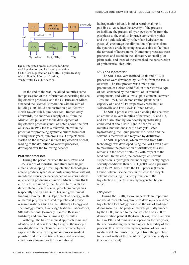
seems to be gasification, which can be fed directlywith coal in addition to the unreacted organic residuesrecovered from the liquefaction unit. The productionof syncrude is thus linked to a single primary fossilsource (Fig. 8).
Using the best available technology, one canestimate that to produce 1 bbl of syncrude from abituminous coal, it is necessary to process about 250kg of coal (daf basis), of which 20-25% is used for theproduction of hydrogen by POx, with an overallperformance of about 70-75%.
2.4.2 Liquefaction technology
Bergius processThe first attempts at direct liquefaction were
carried out in Germany from 1920 by FriedrichBergius. Since then, numerous solutions aimed atimproving the performance and economic viability ofthe process have been proposed and developed, in theattempt to render the direct liquefaction of coal a realviable option for the production of synthetic fuels asan alternative to those obtained from oil.
The Bergius process involved the directhydrogenation of coal at high temperature(430-480°C) and very high pressure (up to 700 bar).To facilitate hydrogenation and avoid problems withthe erosion of materials, the coal was fed to the reactorin the form of a suspension in oil. The reaction wascatalyzed by iron-based materials such as iron oxide orred mud (Bergius and Billiwiller, 1919), a by-productof the aluminium industry based on iron, aluminiumand titanium oxides.
The first industrial plant based on this technologywas built by Farbenindustrie in 1927 at Leuna(Germany), and involved two successivehydrogenation stages. The first, later named LPH(Liquid-Phase Hydrogenation), produced a mediumdistillate which was then further hydrogenated in thevapour phase (second stage) until gasoline and dieselgasoil were obtained. In the following years, severalother plants were built, enabling Germany to producesignificant amounts of fuel to support its war effort:towards the end of the Second World War, the 18 directliquefaction plants and 9 indirect liquefaction plantswere able to produce 4�106 t/y of gasoline, that is 90%of national consumption.
120 ENCYCLOPAEDIA OF HYDROCARBONS
HYDROCARBONS FROM NON-CONVENTIONAL AND ALTERNATIVE FOSSIL RESOURCES
S
1/2
1/2
CH3
CH3 S
Fig. 6. Hydroliquefaction of coal using hydrogen-donor solvents.
coalliquids
gas
mal
tene
asph
alte
ne
coal
prea
spha
lten
eIO
M char
Fig. 7. Block flow diagram of the direct coal liquefaction process.
At the end of the war, the allied countries cameinto possession of the information concerning the coalliquefaction processes, and the US Bureau of Minesfinanced the Bechtel Corporation with the aim ofbuilding a 200 bbl/d demonstration plant fed withNorth Dakota sub-bituminous coal. Immediatelyafterwards, the enormous supply of oil from theMiddle East put a stop to the development ofliquefaction processes until, as noted above, the firstoil shock in 1967 led to a renewed interest in thepotential for producing synthetic crudes from coal.During these years, numerous R&D projects werestarted on the direct and indirect liquefaction of coal,leading to the definition of various processes,developed over the following decades.
Post-war processesDuring the period between the mid-1960s and
1985, a series of industrial initiatives were begun,aimed at developing direct liquefaction technologiesable to produce syncrude at costs competitive with oil,in order to reduce the dependence of western nationson crude oil producing countries. Much of this R&Deffort was sustained by the United States, with thedirect intervention of several petroleum companies(especially Exxon and Gulf Oil), and governmentfunding from the DOE (Department of Energy), withnumerous projects entrusted to public and privateresearch institutes such as the Pittsburgh Energy andTechnology Center, Oak Ridge National Laboratories,SRI International (formerly Stanford ResearchInstitute) and numerous university institutes.
Although the basic chemical approach remainedidentical to that developed by Bergius, the in-depthinvestigation of the chemical and chemico-physicalaspects of the coal hydrogenation process made itpossible to define reaction schemes and operatingconditions allowing for the more rational
hydrogenation of coal, in other words making itpossible to: a) reduce the severity of the process;b) facilitate the process of hydrogen transfer from thegas phase to the coal; c) improve conversion yieldsand the liquid selectivity rather than hydrocarbongases; d ) encourage the elimination of poisons fromthe synthetic crude by using catalysts able to facilitatethe removal of heteroatoms. Numerous processes wereproposed and tested on the laboratory or small pilotplant scale, and three of these reached the constructionof preindustrial-size units.
SRC I and II processesThe SRC I (Solvent Refined Coal) and SRC II
processes were developed by Gulf Oil from the 1960sonwards. The first process was aimed at theproduction of a clean solid fuel, in other words a typeof coal enhanced by the removal of its mineralcomponents, and with a low sulphur content. Between1965 and 1974, two demonstration plants with acapacity of 6 and 50 t/d respectively were built atWilsonville and Fort Lewis (United States).
The SRC I process involves blending the coal withan aromatic solvent in ratios of between 1:2 and 1:3,and its dissolution by low severity hydrotreatingconducted at about 440°C and 70 bar for 30-60minutes, but without specific catalysts. Afterhydrotreating, the liquid product is filtered and thesolvent is recovered and recycled by distillation.
The SRC II process, which evolved from SRCtechnology, was developed using the Fort Lewis plantto maximize the production of distillates; this stillremains in the order of 20-25% with respect to thefeed coal. In this case, the coal-recycled solventsuspension is hydrogenated under significantly higherseverity conditions than SRC I (460°C and a pressureof up to 190 bar). Unlike the EDS process (ExxonDonor Solvent; see below), in this case the recyclesolvent, consisting of a heavy fraction of theliquefaction effluents, is not hydrogenated beforereuse.
EDS processDuring the 1970s, Exxon undertook an important
industrial research programme to develop a new directliquefaction technology based on the use of hydrogendonor solvents. The programme was partially fundedby the DOE, and led to the construction of a 250 t/ddemonstration plant at Baytown (Texas). The plant wasbuilt in 1980 and remained in operation for two years,thus demonstrating the technological feasibility of theprocess: this involves the hydrogenation of coal in amedium able to transfer hydrogen from the gas phaseto the coal without the use of hydrogenation catalysts(H-donor solvent).
121VOLUME III / NEW DEVELOPMENTS: ENERGY, TRANSPORT, SUSTAINABILITY
HYDROCARBONS FROM THE DIRECT LIQUEFACTION OF SOLID FUELS
CLU HDTsyncrude
H2
CO2O2 ashes
coalashes, IOM
H2S, NH3,...
solventdeashing
POx WGSgas
treating
Fig. 8. Integrated process scheme for direct coal liquefaction and hydrogen production. CLU, Coal Liquefaction Unit; HDT, HyDroTreating of coal liquids; POx, gasification; WGS, Water Gas Shift section.

The process scheme involves feeding the coal tothe reactor in the form of a suspension, with a suitablepartially hydrogenated aromatic solvent obtained bythe catalytic hydrogenation of an ad hoc fraction of theproduct of coal conversion on a fixed bed reactor(Fig. 9). The solvent hydrogenation is managed in sucha way as to encourage the production of naphthenicand aromatic structures of the tetrahydronaphthalenetype (tetralin); these then act as hydrogen donorsduring liquefaction. The coal conversion reactoroperates at a temperature of 420-460°C and ahydrogen pressure of 100-140 bar, depending on thetype of coal used. The reaction products are then sentto a fractionation unit to recover the distillates andrecycle solvent; the distillation residue, containing theunreacted organic component and mineral matter, canbe sent to a coking unit to recover an additionalquantity of distillates, and then used as feedstock forgasification to produce the hydrogen needed for theprocess.
The distillate yield obtainable with through EDStechnology depends on the type of coal with which itis fed, but generally ranges from 35-38% for lignitesand low rank coals, up to over 50% for someparticularly reactive bituminous coals (unlessotherwise specified, all the process yields refer to a dafbasis).
H-Coal processThe H-Coal process is a variant of the H-Oil
process for the conversion of petroleum residues,and was developed by Hydrocarbon Research (nowHydrocarbon Technology) in the early 1980s. Thecoal, suspended in a recycle solvent, is catalytically
hydrogenated at a temperature of 425-450°C and apressure of 200 bar in an ebullated bed reactor,using pellet catalysts based on NiMo or CoMo overalumina, with a size of 0.8-1.5 mm. The technologyused makes it possible to constantly replace thecatalyst poisoned by the contaminants present in thecoal with fresh catalyst, so as to maintain constantperformance over time in terms of conversion andupgrading. The conversion products exiting the plantare fractionated, and then further hydrogenated usingtraditional fixed bed technologies; the distillationresidue can be recycled and used for the initialpreparation of the coal-oil suspension. As for otherliquefaction processes, in this case, too, yieldsdepend on the type of feed; for bituminous coals,they are in the order of 50%.
A 200 t/d pilot plant for this process was built atCatlettsburgh (Kentucky), which remained inoperation until 1983. The H-Coal technology was thentaken up again and further developed over at least tenyears (up to 1992) in a smaller plant built atWilsonville, directly funded by the DOE.
TSL processes (Two-Stage Liquefaction)The processes described above were considered a
success from the standpoint of their technicalfeasibility, but were not yet able to produce syncrudeat costs competitive with oil. The main problems werethe low distillate yields and the high consumption ofhydrogen due to excess production of gas. Acontribution of fundamental importance to overcomingthese problems was made by studies on the chemismof liquefaction carried out at various American stateand university research centres, under the supervision
122 ENCYCLOPAEDIA OF HYDROCARBONS
HYDROCARBONS FROM NON-CONVENTIONAL AND ALTERNATIVE FOSSIL RESOURCES
slurrymixing
fixed bedhydrotreater
separation
gases naphtha
preheating
recycle solventcoke to
gasification
tubularreactor
vacuumdistillation
middledistillate
flexicoker
coal
fresh hydrogen
recycle hydrogenFig. 9. Block flowdiagram of the EDSprocess (HarwellLaboratory, 1999).
of the DOE. These clarified numerous aspects of themolecular structure of coal and its reactivity during thevarious phases of the process of transformation intoliquids and distillates.
In 1976, Richard Neavel demonstrated that it ispossible to almost completely solubilize coal underrelatively mild conditions without consuminghydrogen (Neavel, 1976). He proved that, by heatingcoal to 400°C in the presence of suitable polynucleararomatic solvents, even after a few minutes yieldsabove 90% of products soluble in polar solvents couldbe obtained. People also began to consider theimportance of the solvent not only as a hydrogendonor but also as an agent able to promote thedissolution of the coal and encourage the transfer ofhydrogen from the gas to the liquid phase. Solvents ofthis type thus had to consist of aromatic andhydroaromatic hydrocarbons, but also of compoundscontaining heteroatoms such as oxygen and nitrogenwith phenol and pyridine functionality, preferably witha high molecular weight. The same group of Exxonresearchers who had followed the development of theEDS process – and who had already identifiedstandard methods for evaluating the properties ofdonor solvents (solvent quality index) – discoveredthat recycling heavy hydrocarbon residues led to asubstantial increase in conversion yields (Schlosberg,1985).
These considerations made it possible todevelop a new two-stage process scheme, in whichcoal dissolution and upgrading were separated,reducing the disadvantages entailed by a singlehigh-severity stage. The first stage had to beoptimized to encourage the complete dissolution ofthe coal, minimizing the consumption of hydrogen.This was obtained by reducing the severityconditions and, in particular, by lowering residencetimes to a few minutes (short contact time).Subsequently, the solubilized coal could be freedfrom mineral substances and sent to the secondcatalytic hydrogenation stage, optimized tomaximize conversion and upgrading.
One of the first plants based on this newscheme was built by Lummus Crest in early 1980.The 0.2 t/d plant consisted of a first thermaldissolution reactor operating at 430-450°C underhydrogen pressure, followed by an LC-Finingebullated bed unit for the catalytic hydrogenationof the liquid products. This process configuration,described with the acronym ITSL (Integrated Two-Stage Liquefaction) was taken up and studied onvarious scales by numerous companies (Amoco,Chevron, HRI and others).
Much of the work to develop this technologywas carried out over almost a decade at the 6t/d
Wilsonville plant, built in 1972 by SouthernCompany, but from the following year fell under thetechnical and financial control of the Electric PowerResearch Institute (EPRI). In 1976, the DOEbecame the project’s major financial backer. In1978, with the completion of a new reactor coupledwith the hydrotreating reactor, the integrated ITSLscheme was developed. The thermal treatmentreactor is fed with a slurry of coal-recycle solventand with hydrogen; the reaction pressure andtemperature are 90-150 bar and 400-450°Crespectively. The product exiting the reactor (solidat ambient temperature) is fractionated into gas,distillates and residue, and in turn sent to a unit thatremoves the mineral component (Kerr-McGeeCritical Solvent Deashing). It then passes into thecatalytic hydrogenation reactor (ebullated bedplant) operating at a temperature of between390-400°C in the presence of traditional supportedcatalysts used to treat extremely heavy feedstocks.Using this type of configuration, the Wilsonvilleplant managed to significantly reduce hydrogenconsumption, halving the production of gas andmaintaining yields of distillable products(C5-350°C) above 60%.
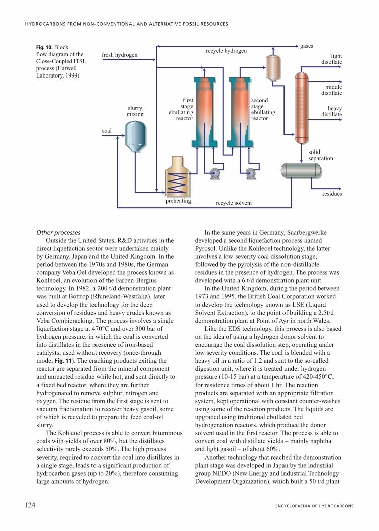
In around 1990, a further development of the ITSLprocess was created, using two H-Oil reactors in aseries before the deashing unit. This configuration(Close-Coupled ITSL) made it possible to couple thethermal and catalytic treatment stages without anintermediate reduction of pressure (Fig. 10).Furthermore, it was particularly attractive because itmade it possible to further limit the negative effects ofrepolymerization reactions, improving yields and thequality of products.
These ideas formed the basis for the variousprocess options developed during the 1990s by HTI(Hydrocarbon Technologies Inc.), involving the useof two or more slurry and/or ebullated bed reactors,and therefore described with the name CTLS(Catalytic Two-Stage Liquefaction) and CMSL(Catalytic Multi-Stage Liquefaction; see Section2.4.3). The distillate yields obtainable with the latterconfigurations can reach values of over 70%, with ahydrogen consumption of 6-7.5 weight % on feed.Of the total hydrogen consumed, about 70% is usedto produce liquids, 20% to remove heteroatoms, andonly 10% to produce gaseous hydrocarbons. In mostof the single-stage processes developed earlier, only50% of the hydrogen consumed ended up in theliquids. The research carried out at Wilsonvillecontinued until 1992, concentrating on the study ofcoprocessing, in other words the combinedupgrading of coal and petroleum residues or heavycrudes (see below).
123VOLUME III / NEW DEVELOPMENTS: ENERGY, TRANSPORT, SUSTAINABILITY
HYDROCARBONS FROM THE DIRECT LIQUEFACTION OF SOLID FUELS
Other processesOutside the United States, R&D activities in the
direct liquefaction sector were undertaken mainlyby Germany, Japan and the United Kingdom. In theperiod between the 1970s and 1980s, the Germancompany Veba Oel developed the process known asKohleoel, an evolution of the Farben-Bergiustechnology. In 1982, a 200 t/d demonstration plantwas built at Bottrop (Rhineland-Westfalia), laterused to develop the technology for the deepconversion of residues and heavy crudes known asVeba Combicracking. The process involves a singleliquefaction stage at 470°C and over 300 bar ofhydrogen pressure, in which the coal is convertedinto distillates in the presence of iron-basedcatalysts, used without recovery (once-throughmode; Fig. 11). The cracking products exiting thereactor are separated from the mineral componentand unreacted residue while hot, and sent directly toa fixed bed reactor, where they are furtherhydrogenated to remove sulphur, nitrogen andoxygen. The residue from the first stage is sent tovacuum fractionation to recover heavy gasoil, someof which is recycled to prepare the feed coal-oilslurry.
The Kohleoel process is able to convert bituminouscoals with yields of over 80%, but the distillatesselectivity rarely exceeds 50%. The high processseverity, required to convert the coal into distillates ina single stage, leads to a significant production ofhydrocarbon gases (up to 20%), therefore consuminglarge amounts of hydrogen.
In the same years in Germany, Saarbergwerkedeveloped a second liquefaction process namedPyrosol. Unlike the Kohleoel technology, the latterinvolves a low-severity coal dissolution stage,followed by the pyrolysis of the non-distillableresidues in the presence of hydrogen. The process wasdeveloped with a 6 t/d demonstration plant unit.
In the United Kingdom, during the period between1973 and 1995, the British Coal Corporation workedto develop the technology known as LSE (LiquidSolvent Extraction), to the point of building a 2.5t/ddemonstration plant at Point of Ayr in north Wales.
Like the EDS technology, this process is also basedon the idea of using a hydrogen donor solvent toencourage the coal dissolution step, operating underlow severity conditions. The coal is blended with aheavy oil in a ratio of 1:2 and sent to the so-calleddigestion unit, where it is treated under hydrogenpressure (10-15 bar) at a temperature of 420-450°C,for residence times of about 1 hr. The reactionproducts are separated with an appropriate filtrationsystem, kept operational with constant counter-washesusing some of the reaction products. The liquids areupgraded using traditional ebullated bedhydrogenation reactors, which produce the donorsolvent used in the first reactor. The process is able toconvert coal with distillate yields – mainly naphthaand light gasoil – of about 60%.
Another technology that reached the demonstrationplant stage was developed in Japan by the industrialgroup NEDO (New Energy and Industrial TechnologyDevelopment Organization), which built a 50 t/d plant
124 ENCYCLOPAEDIA OF HYDROCARBONS
HYDROCARBONS FROM NON-CONVENTIONAL AND ALTERNATIVE FOSSIL RESOURCES
slurrymixing
gases
lightdistillate
preheating recycle solvent
recycle hydrogen
firststage
ebullatingreactor
secondstageebullatingreactor
solidseparation
heavydistillate
residues
middledistillate
coal
fresh hydrogenFig. 10. Blockflow diagram of theClose-Coupled ITSLprocess (HarwellLaboratory, 1999).

at Morwell in Australia in 1985. This technology,known as BCL (Brown Coal Liquefaction) is specificfor low rank coals, which may contain significantquantities of water, and involves the liquefaction of thecoal aided by a heavy oil and a limonite-basedcatalyst, used once-through. As for other processes, inthis case as well, the liquefaction step (150 bar,430-450°C) is integrated with the hydrogenation of theproducts.
Coprocessing technologiesCoprocessing involves the simultaneous upgrading
of coal and petroleum residues or heavy crudes, whichare co-fed to the hydrogenation reactor in ratiosbetween 1:1 and 1:2.
The idea of coprocessing coal and oil dates to the1930s, with the first attempts in Canada using thebitumen extracted from the Athabasca tar sands andcoal. In any case, most studies relating to thedevelopment of coprocessing technologies began inthe 1970s in connection with those on direct coalliquefaction. Liquefaction plants worked byrecycling some of the products (distillates ordistillation residues) used as a carrier and/or reactivefluid for the coal to be liquefied. Using low-costoils, such as distillation residues or heavy crudes, tobe processed alongside the coal has the practicaladvantage of eliminating the solvent recycling stage,thus simplifying the process and reducing specificinvestment costs per unit of product. From therefiner’s point of view, replacing some of the oilwith coal in residue conversion plants may entailbenefits linked to the reduction of upgrading costsper barrel of product.
Often, studies on coprocessing have attempted toidentify the conditions under which the combinedtreatment of coal and oil produces synergic effects thatmay lead to improved yields and product quality ascompared with the separate treatment of the twofeedstocks. According to SRI International researchers(McMillen et al., 1987), one possible advantage ofcoprocessing may be due to the fact that thesimultaneous presence in the feedstock of hydrogenacceptor compounds (such as the PolyNuclearAromatic hydrocarbons in coal, PNA) and hydrogendonors (such as the naphthenes in oil) may lead to theproduction of cyclohexadienyl radicals whichencourage cracking reactions through freeradical-based hydrogen transfer reactions (H-transferreaction; Fig. 12). It also appears that the combinedtreatment of oil and coal provides benefits in terms ofproduct quality. For example, the presence of coaltends to favour the precipitation of the metals presentin the oil, leading to a lowering of the nickel andvanadium content in the conversion products. Bycontrast, the properties of oils of petroleum origin ascoal dissolution solvents are significantly worse thanthose of the liquids produced by the coal itself, sincethey contain significant quantities of paraffinic andnaphthenic hydrocarbons.
Coprocessing has long been studied by variousNorth American companies (HRI, UOP, Lummus,Mobil, Chevron, Ohio Ontario, Canada Centre forMineral and Energy Technology – CANMET, AlbertaResearch Council) and Japanese companies (Ministryof International Trade and Industry – MITI, OsakaGas, Mitsubishi Heavy Industries), often reaching theexperimental phase at the laboratory or pilot plant
125VOLUME III / NEW DEVELOPMENTS: ENERGY, TRANSPORT, SUSTAINABILITY
HYDROCARBONS FROM THE DIRECT LIQUEFACTION OF SOLID FUELS
hydrogen recycle hydrogen
separation
hydr
otre
atin
g
catalyst
slurrymixing
prim
ary
reac
tion
flas
h se
para
tor
vacu
umdi
stil
lati
on
atm
osph
eric
dist
illa
tion
vacuum bottoms
gases
LPG
naphtha
middleoilrecycle solvent
coal
Fig. 11. Block flowdiagram of theKohleoel process(Harwell Laboratory,1999).

scale (various t/d), but hardly ever on thedemonstration plant scale. Some major experiments oncoprocessing technologies have been carried out inCanada, which possesses enormous quantities ofheavy crudes and tar sands, and which has developedspecific experience in the treatment of thesefeedstocks over the past 30 years. The CANMETcoprocessing technology is a variant of that developedto the 5,000 bbl/d plant scale at the Montreal refineryfor the hydrocracking of petroleum residues and heavycrudes. Using the same process solutions (multiphasesingle-stage reactor operating at 440-460°C and apressure of up to 150 bar) and the same type ofcatalyst (iron sulphate) the potential for cofeeding30-40% of coal with the oil was assessed. Theexperiment was carried out on a plant of reduced size,obtaining good levels of coal to liquids conversion.
The solution adopted by the ARC (AlbertaResearch Council), on the other hand, is specific forlow rank coals and Canadian bitumens. The processinvolves a first stage of coal liquefaction in a blendwith oil, conducted in a carbon monoxide atmosphereso as to use the water present in the coal as a source ofhydrogen through the Water-Gas-Shift Reaction(WGSR). The reaction takes place in a reactor intowhich the feedstock and reactive atmosphere are fed incounter-flow (CFR, Counter-Flow Reactor), with thegas sent in from below to desorb the lighter reactionproducts. The reaction conditions are relatively mild(temperature below 400°C and pressure below 100bar), but make it possible to convert the coal intoliquids with yields above 90%, removing most of theoxygen present in the feedstock. Subsequently, theliquid is subjected to upgrading in a secondmultiphase hydrogenation reactor, obtaining distillateyields of nearly 70%. The first stage of this processhas been tested up to the 0.25 t/d scale.
2.4.3 New-generation processes
Though at rates and attracting investmentssignificantly lower than those lavished on it during the1970-1980s, research in the field of direct liquefactionprocesses continued during the last decade of thetwentieth century, with special attention to specificapplications in countries of the Asia-Pacific region,and particularly China, Japan and Australia. These
countries possess enormous reserves of coal (but notof oil) and thus, given the forecasts of strong economicgrowth, deem it strategically important to invest in thistechnology. During recent years, various industrialinitiatives have begun which should lead to theconstruction of the first industrial-scale plants for theproduction of syncrude from coal since the post-Warperiod.
HTI-Shenhua projectThe main industrial initiative, which should
become concrete in 2010, concerns the HTI(Hydrocarbon Technologies Inc.) and Shenhua GroupCorporation. During the 1990s, HydrocarbonTechnologies (a spin-off of Hydrocarbon Research,now controlled by Headwaters) worked on thedevelopment of numerous technologies for theupgrading of petroleum residues, heavy crudes, thedirect liquefaction of coal and coprocessing, centredon the use of dispersed catalysts obtained fromdifferent precursors based on iron and/ormolybdenum. The portfolio of processes and catalystsproposed by HTI is extremely broad:• HTI GelCat is a dispersed catalyst based on iron
oxide, used in the form of a gel in concentrations ofup to 5,000 ppm and potentially containingpromoters such as Molyvan (an oil-solublecompound based on molybdenum, added up to100-200 ppm of molybdenum) or other transitionmetals such as cobalt, nickel, palladium andplatinum. The application of choice appears to becoal-oil coprocessing. The advantage of using thecatalyst in gel form results from the fact that uponentering the reactor, as an effect of the hightemperature, there is an ‘explosion’ caused by therapid evaporation of the water. This producesextremely fine particles with a very high surfacearea, allowing them to be used at low concentrations(a few thousand ppm of iron). Operating costs arethus lowered, since these catalysts cannot berecycled directly, and are therefore lost with theunconverted residue and ashes.
• HTI (HC)3, technology for the upgrading of heavycrudes, uses a dispersed molybdenum-basedcatalyst originally developed by the ARC.
• HTI Resid-Cat entails the hydrocracking of heavyfeedstocks of various types into ultradesulphurizeddistillates.
126 ENCYCLOPAEDIA OF HYDROCARBONS
HYDROCARBONS FROM NON-CONVENTIONAL AND ALTERNATIVE FOSSIL RESOURCES
H H H
� � �
H
. . coalcoal
coal.
Fig. 12. Cleavage of bonds by H-transferreaction (McMillen et al., 1987).

• HTI Co-Pro and HTI Co-ProPlus, upgrades thecombined coal-residue feedstocks derived from(HC)3.
• HTI Coal is the direct liquefaction of coal based onCTSL, that is a process based on the distinctionbetween the stage of conversion into liquids(liquefaction of the organic component) and that ofconversion into distillates and upgrading. As amatter of fact, the process involves a stage ofhydrogenation of the feedstock, previouslyimpregnated with a dispersed iron-based catalyst(GelCat) and blended with some of the heavy oilsproduced by the process itself at a temperature ofbetween 400 and 420°C and a hydrogen pressure of170 bar. The low temperatures make it possible tomaintain a high concentration ofnaphthenic-aromatic structures in the reactionsystem to better control repolymerizationprocesses. The liquid produced can then be sentinto a second hydroconversion unit, at a highertemperature to maximize conversion intodistillates. These are recovered and further treatedthrough a series of flashing operations, vacuumdistillation, final residue extraction with tolueneand hydrotreating. To better control the initial coaldissolution process, it is possible to operate with asystem of several stages conducted at differentseverities. The conversion yields claimed for thisprocess are extremely high (�90%) with adistillates selectivity of around 75%.The latter technology has been developed with a 50
kg/d pilot plant unit; recently, Headwaters announcedthe formalization of an agreement with the Chinesecoal company Shenhua Group (with an annualproduction of 60 million t of coal) to build a plant forthe direct conversion of coal into hydrocarbondistillates. The plant will be built on an HTI licence asfar as the liquefaction stage is concerned, whereasliquid upgrading will be carried out using Axenstechnology. The industrial complex is due to becompleted by 2008 at Baotou in Inner Mongolia(China), and will have a production capacity of 50,000bpd (barrels per day) of distillates (mainly gasolineand gasoil) obtained by processing about 12,800 t/d ofsub-bituminous Shenhua coal on six production lines.The level of conversion of coal into liquids has beenestimated at around 91-93%, with a distillate yield of63-68 weight % on feed, of which naphtha andmedium distillates represent about 20 and 50%respectively. Hydrogen consumption is in the order of6.5 weight % on feed. The gasoline and gasoilproduced will have very good quality characteristics,at least as far as the sulphur content is concerned (15and 140 ppm respectively); the properties of thesyncrude are summarized in Table 4 (Comolli et al.,
1999). The companies involved in the project have notprovided information on the economic aspects of theinitiative, but claim that the availability of enormouscoal reserves and low production costs will render itprofitable when crude oil prices are above 30 $/bbl.
NEDOL processA second initiative, announced in 2001, concerns a
plant to be built in Sumatra (Indonesia) by 2011, theresult of collaboration between the Indonesian statecompany BPPT (Badan Pengkajian dan PenerapanTeknologi) and the Japanese group NEDO (NewEnergy and industrial technology DevelopmentOrganisation). The reference technology for theliquefaction section is the NEDOL process, developedin Japan from the early 1980s and perfected overvarious years of experimentation carried out as part ofa joint programme with the Chinese ministry forindustry, later tested on a 7 t/d pilot plant, which is stillin operation (Wasaka et al., 2003).
The process has four macrosections: a) preparationof the coal feed, in other words dewatering, reductionto an extremely fine powder, blending with the solventand the catalyst (natural or synthetic pyrite);b) liquefaction in three slurry reactors in series at450-465°C and 180-190 bar, with residence times forthe liquid phase of 1.5-3 hr; c) distillation(atmospheric and vacuum) with the separation of thefractions (gas, naphtha, residue and solvent);d ) recovery and hydrogenation of part of the gasoilused as a coal liquefaction solvent, with recycling tothe feed preparation section.
The peculiarities of this process are thus thecombined use of low-cost donor solvents andiron-based catalysts, and the replacement of the
127VOLUME III / NEW DEVELOPMENTS: ENERGY, TRANSPORT, SUSTAINABILITY
HYDROCARBONS FROM THE DIRECT LIQUEFACTION OF SOLID FUELS
Table 4. Elemental composition of Shenhua coaland the syncrude produced with the HTI technology
(Comolli et al., 1999)
Coal Syncrude
Elemental composition (% daf)
Carbon 75.9 87.0
Hydrogen 4.2 12.7
Sulphur 0.42 0.10
Nitrogen 0.98 0.14
Oxygen 12.3 0,06*
Ash 6.2 –
API Gravity 29.7
* The oxygen content is given by the difference between 100 and thesum total of the other elements.
deashing stage (the critical stage in all direct coalliquefaction processes) with vacuum distillation, fromwhich the unreacted organic residue is dischargedtogether with other ashes and fed to a gasification unitfor the production of hydrogen. Liquefaction yields arein the order of 65% with a selectivity for naphtha andgasoil of 85%.
2.4.4 Properties of coal liquids
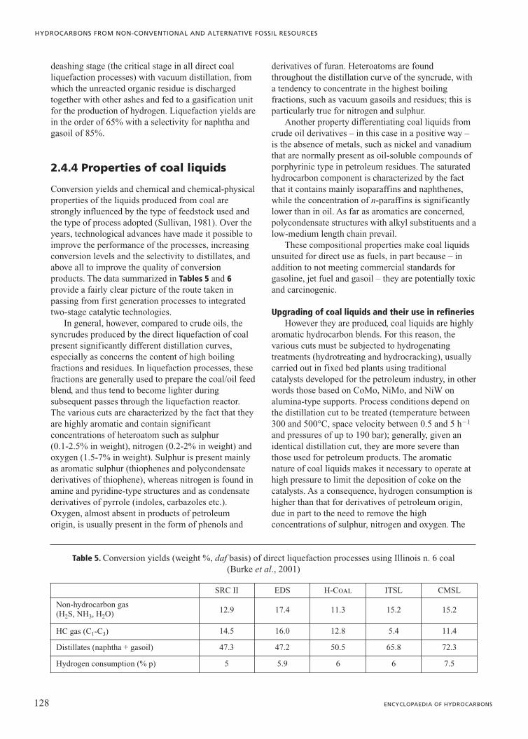
Conversion yields and chemical and chemical-physicalproperties of the liquids produced from coal arestrongly influenced by the type of feedstock used andthe type of process adopted (Sullivan, 1981). Over theyears, technological advances have made it possible toimprove the performance of the processes, increasingconversion levels and the selectivity to distillates, andabove all to improve the quality of conversionproducts. The data summarized in Tables 5 and 6provide a fairly clear picture of the route taken inpassing from first generation processes to integratedtwo-stage catalytic technologies.
In general, however, compared to crude oils, thesyncrudes produced by the direct liquefaction of coalpresent significantly different distillation curves,especially as concerns the content of high boilingfractions and residues. In liquefaction processes, thesefractions are generally used to prepare the coal/oil feedblend, and thus tend to become lighter duringsubsequent passes through the liquefaction reactor.The various cuts are characterized by the fact that theyare highly aromatic and contain significantconcentrations of heteroatom such as sulphur(0.1-2.5% in weight), nitrogen (0.2-2% in weight) andoxygen (1.5-7% in weight). Sulphur is present mainlyas aromatic sulphur (thiophenes and polycondensatederivatives of thiophene), whereas nitrogen is found inamine and pyridine-type structures and as condensatederivatives of pyrrole (indoles, carbazoles etc.).Oxygen, almost absent in products of petroleumorigin, is usually present in the form of phenols and
derivatives of furan. Heteroatoms are foundthroughout the distillation curve of the syncrude, witha tendency to concentrate in the highest boilingfractions, such as vacuum gasoils and residues; this isparticularly true for nitrogen and sulphur.
Another property differentiating coal liquids fromcrude oil derivatives – in this case in a positive way –is the absence of metals, such as nickel and vanadiumthat are normally present as oil-soluble compounds ofporphyrinic type in petroleum residues. The saturatedhydrocarbon component is characterized by the factthat it contains mainly isoparaffins and naphthenes,while the concentration of n-paraffins is significantlylower than in oil. As far as aromatics are concerned,polycondensate structures with alkyl substituents and alow-medium length chain prevail.
These compositional properties make coal liquidsunsuited for direct use as fuels, in part because – inaddition to not meeting commercial standards forgasoline, jet fuel and gasoil – they are potentially toxicand carcinogenic.
Upgrading of coal liquids and their use in refineriesHowever they are produced, coal liquids are highly
aromatic hydrocarbon blends. For this reason, thevarious cuts must be subjected to hydrogenatingtreatments (hydrotreating and hydrocracking), usuallycarried out in fixed bed plants using traditionalcatalysts developed for the petroleum industry, in otherwords those based on CoMo, NiMo, and NiW onalumina-type supports. Process conditions depend onthe distillation cut to be treated (temperature between300 and 500°C, space velocity between 0.5 and 5 h�1
and pressures of up to 190 bar); generally, given anidentical distillation cut, they are more severe thanthose used for petroleum products. The aromaticnature of coal liquids makes it necessary to operate athigh pressure to limit the deposition of coke on thecatalysts. As a consequence, hydrogen consumption ishigher than that for derivatives of petroleum origin,due in part to the need to remove the highconcentrations of sulphur, nitrogen and oxygen. The
128 ENCYCLOPAEDIA OF HYDROCARBONS
HYDROCARBONS FROM NON-CONVENTIONAL AND ALTERNATIVE FOSSIL RESOURCES
Table 5. Conversion yields (weight %, daf basis) of direct liquefaction processes using Illinois n. 6 coal(Burke et al., 2001)
SRC II EDS H-Coal ITSL CMSL
Non-hydrocarbon gas(H2S, NH3, H2O) 12.9 17.4 11.3 15.2 15.2
HC gas (C1-C3) 14.5 16.0 12.8 5.4 11.4
Distillates (naphtha + gasoil) 47.3 47.2 50.5 65.8 72.3
Hydrogen consumption (% p) 5 5.9 6 6 7.5

life of catalysts is heavily conditioned by the tendencyof feedstocks to form coke and the more or lesssignificant presence of inorganic particles due to themineral component of coal, which is not always easyto remove.
All these factors entail high additional costs;however, these can be partially lowered by suitablyintegrating direct liquefaction plants with therefinery. Although there are no sufficiently detailedand up-to-date studies on this subject, it isreasonable to assume that it will be possible toidentify synergies able to reduce the productioncosts for finished fuels by intervening appropriatelyon the units devoted to reaching commercialspecifications and blending methods. For example,hydrotreated naphtha from liquefaction processes isan excellent feedstock for reforming units since itcontains high concentrations of cyclic hydrocarbons,which are easy to convert into aromatichydrocarbons with a high octane content. As such,this naphtha can produce a component for gasolineof excellent quality, in addition to benzene, tolueneand xylenes for the petrochemical industry.
In order to be turned into jet fuel, the kerosenefraction must be strongly hydrogenated to reach thesmoke point values required by current specifications.This generates hydrocarbon blends containing highconcentrations of naphthenes with two rings (decalins),which have high heat of combustion in volumetricterms, excellent stability and very low freezing points:all properties which make them particularly suited ascomponents of high quality jet fuels. As far as the
diesel fraction is concerned, it is also necessary tohydrotreat middle distillates, but in this case the lowconcentration of n-paraffins may make it difficult toreach density and cetane number specifications unlessthere is specific intervention on the naphthenecomponent (ring opening). From this point of view, thegasoil from direct liquefaction is similar to the LCO(Light Cycle Oil) from catalytic cracking, for whichsuitable upgrading processes are being developed.
Finally, heavy distillates and residues can besuitably treated in conversion units alongside productsof petroleum origin, since they ‘dilute’ the heavy metalcontent characteristic of residues derived from oil; inaddition, their highly aromatic nature may contributeto improving the stability of conversion products withrespect to asphaltene precipitation phenomena, makingit possible to increase conversion into distillateswithout affecting the stability of the fuel oil produced.
2.4.5 Further developments of the technology
One of the main objectives of research in the field ofdirect liquefaction is to improve knowledge of processchemistry. This makes it possible to identify solutionscapable of lowering investment costs by reducingseverity conditions (temperature and pressure) andcontaining operating costs, determined mainly by theconsumption of hydrogen and catalysts. Other effortsto improve the economic feasibility of the processconcern specific technological aspects such as the
129VOLUME III / NEW DEVELOPMENTS: ENERGY, TRANSPORT, SUSTAINABILITY
HYDROCARBONS FROM THE DIRECT LIQUEFACTION OF SOLID FUELS
Table 6. Liquid products’ quality from direct coal liquefaction processes using Illinois n. 6 coal(Burke et al., 2001)
SRC II EDS H-Coal ITSL CMSL
Naphtha
Yield (weight %) 19.3 22.8 22.9 14.5 20.7
API Gravity 39 31 35 50 53
Sulphur (weight %) 0.2 0.5 0.2 0.04 0.02
Nitrogen (weight %) 0.4 0.2 0.3 0.02 0.002
Oxygen (weight %) 3.9 2.8 3.0 0.3 �0.1
Syncrude
API Gravity 27 22 38
Sulphur (weight %) 0.2 0.1 0.1
Nitrogen (weight %) 0.5 0.5 �50 ppm
Oxygen (weight %) 2.1 2.2 0.5

separation of liquids from the mineral component andunreacted organic materials.
Numerous attempts have also been made toevaluate the potential offered by so-called‘non-conventional approaches’, that is solutions usinga chemistry different from that of hydrocracking.
PretreatmentIt has already been noted that, in general,
liquefaction processes involve heating the coal rapidlyto a temperature usually between 400 and 450°C;under these conditions this causes the instantaneousproduction of reactive fragments (free radicalsproduced by thermal cracking), which, if notimmediately saturated by hydrogenating reactions,tend to recombine forming char (see again Fig. 4).
The reducing agent present in the system is notalways able to compete effectively withrepolymerization reactions; for this reason, it may bepreferable to control the production of free radicals byusing increasing temperature stages or lowtemperature pretreatment stages (Temperature-StagedLiquefaction). Numerous studies have confirmed that,by operating with stages of increasing temperaturefrom 200-350 up to 450°C, it is possible to increaseconversion yields with respect to the adoption ofisothermal conditions at high temperature (Derbyshireet al., 1986).
New catalytic systemsThe development potential of direct liquefaction
processes is closely linked to the improvement ofcatalytic systems. Catalysts for liquefaction processesmust guarantee an increase in the reaction velocity ofhydrogen transfer processes, limiting repolymerizationreactions to allow a high level of upgrading to beobtained even at low severity.
In this context, if a distinction is made between thetwo main phases involved in liquefaction – coaldissolution and upgrading –, it is reasonable tosuppose that it is better to use dispersed catalysts inthe first stage, whereas it is preferable to usesupported catalysts in the second.
As far as the former are concerned, althoughnumerous basic studies have been carried out,experiments at the level of pilot plant have mainlybeen limited to the oxides and sulphides of metalssuch as iron, molybdenum and a few others. For allthese, the most important property is the capacity foradequate dispersal throughout the feedstock. Gooddispersion makes the catalyst available on a local level,limiting the production of char; this also reduces theconsumption of catalyst, which cannot be easilyrecovered in this stage of the process since it mixeswith the mineral component of the coal.
A good hydrogenation catalysts’ dispersion can beobtained by using water or oil-soluble precursors. Thisis the case for sulphides of iron, molybdenum or othertransition metals, which are generated in situ by thedecomposition and sulphidation by endogenous (orsuitably added) sulphur of water-soluble precursors,such as iron sulphate, ammonium molybdate etc., oroil-soluble precursors, like some organic carboxylatessuch as molybdenum-naphthenate or othermetallorganic derivatives such as Molyvan A (N,N-dibutyldithiocarbamate of oxythiomolybdenum).
Studies of the efficacy of molybdenum-basedcatalytic systems at low concentrations (hundreds ofppm) were started by Clyde Aldridge and RobyBearden at Exxon in the late 1970s (Aldridge andBearden, 1978) and were taken up by numerous othercompanies and research institutes, both forapplications in the field of direct liquefaction and forthe development of upgrading technologies for heavycrudes (Montanari et al., 2003). As already noted,microcrystalline molybdite, which is generated in situfrom oil-soluble precursors, presents as a very finepowder, consisting of nanometric particles ofmolybdenum sulphide (MoS2) with a low degree ofaggregation, highly dispersed within the feedstock. Itsmorphology and the absence of porous supports rendermolybdenite particularly suitable for workingeffectively as a hydrogenation catalyst in systemswhich are particularly difficult to upgrade due to thepresence of high concentrations of poisons, such ascoal ashes or the heavy metals present inconcentrations of up to 700-800 ppm in some heavycrudes (such as the Venezuelan extra heavy crudesproduced in the Orinoco belt).
In the attempt to further increase the ratio betweenthe degree of dispersion as well as the specific activity– and thus reduce the concentration of the active phasewhile maintaining an identical catalytic effect –,numerous other systems have been proposed andstudied, able to produce micrometric orsubmicrometric particles of transition metal sulphidesand nitrites. Examples are the use of specificprecursors containing heteroatoms or bimetallicpairings, laser-pyrolysis, plasma techniques,microemulsions etc. (Delbianco et al., 1995). None ofthese attempts, however, seem able to significantlyimprove the performances obtainable withmolybdenite generated in situ, as described above.
Another critical aspect of the use of dispersedcatalysts concerns their recovery or, more accurately,the impossibility of recovering them from theunconverted product at an acceptable cost. For thisreason, economic considerations have limitedexperiments to low cost materials, and especially iron,sometimes promoted with the addition of small
130 ENCYCLOPAEDIA OF HYDROCARBONS
HYDROCARBONS FROM NON-CONVENTIONAL AND ALTERNATIVE FOSSIL RESOURCES
quantities of molybdenum and other metals, such aswolfram, ruthenium, etc.
Supported catalysts are generally proposed andused in the second phase of the process to producedistillates, that which transforms the syncrude fromcoal, still highly aromatic and rich in heteroatoms, intonaphtha and gasoil with a low sulphur, nitrogen andoxygen content. In general, the catalysts used areclassic hydrotreating catalysts developed for theupgrading of petroleum products. However, since coalliquids have fairly different properties from those ofcomparable distillation cuts or residues deriving frompetroleum, the performance of these catalysts are oftenlower, both in terms of efficacy and life.
To prepare suitably tailored catalysts, supportswhich are less sensitive to the deposition of coke areused (stabilized aluminas, active carbons with a highsurface area, etc.) alongside active phases speciallysuited to removing nitrogen compounds, in particularthe pairing Ni/W, Ru, etc. (Derbyshire, 1988).However, the lack of genuine industrial interest has notencouraged research on tailor-making these catalysts.
Product separation technologiesOne of the major critical aspects of technological
type inherent in liquefaction processes is theseparation of the liquids produced in the first stage ofthe process from the mineral component of theoriginal coal. Among the proposed solutions, inaddition to classic filtration and centrifuging, solventextraction seems to provide the best performance. Aparticularly interesting solution has been developed byKerr McGee along the lines of deasphalting processes,known as solvent deashing. This involves a multi-stageextraction of the products of coal conversion withtoluene-type solvents, used in a ratio of 2:1 withrespect to the feedstock to be treated, at a temperatureclose to 200°C. This system makes it possible to easilyseparate the insoluble fraction (ashes and unreactedcoal and IOM which can be gasified to produce thehydrogen needed for the liquefaction reaction) fromthe extract, from which the solvent is then recoveredby suitably varying the temperature and pressure. Thistechnology seems to be fairly consolidated, althoughthere are optimization margins in the choice ofsolvents and process conditions.
The simplest way of overcoming the deashingproblem involves the prior removal of the mineralcomponent with coal beneficiation processes.
Using coals treated in this way may be extremelyadvantageous from an operational point of view, inpart due to the potential for using the most suitablecatalytic systems from the very first stage. However,beneficiation processes are not particularly selective,in the sense that they are unable to remove the mineral
component completely, and in any case entailadditional costs. For this reason, it is necessary toexamine all the implications of a pretreatment processupstream of liquefaction on a case by case basis,evaluating the cost/benefit ratio of this operation.
New conversion systemsOver the years, research on new coal conversion
routes has suggested several solutions that arecertainly of interest from the standpoint of knowledge,but which for various reasons cannot currently beconsidered equally valid from an industrial point ofview (cost, process complexity, performance, etc.).Among these are the use of water-based systems, acidcatalysts and bioconversion.
Water-based systemsThe first studies of the use of water and carbon
monoxide to liquefy low rank coal were carried out byFranz Fischer in around 1920. More recently, thissolution has been taken up again and widely studied atvarious research centres (Pittsburgh Energy ResearchCenter, SRI International, Eni and others); it isgenerally known by the name of Costeam or CO-steamliquefaction (Ross, 1984).
In Costeam, the hydrogen is produced in situ by theWGS reaction, suitably catalyzed by alkalis such assodium carbonate. According to various authors, thereaction to convert coal into liquids may in this case,rather than following a non-radical mechanism, bepromoted by the formiate ion, that is the intermediateof the WGS reaction. Additionally, under the reactionconditions adopted (T �400°C and a pressure of over200 bar), the water is in almost supercritical conditionsand thus constitutes an excellent reaction medium,able to solvate the organic fragments deriving fromcracking processes.
Costeam seems particularly suited to liquefying lowrank coals, which usually contain large amounts ofwater (up to 60%). The experimental evidence obtainedshows that this process is able to guarantee highconversions of coal to liquids, and seems particularlyeffective at removing heteroatoms, especially oxygen.Other potential advantages concern the non-use oforganic solvents and the direct use of syngas rather thanpure hydrogen. However, it requires extremely severereaction conditions, especially as concerns pressure (adirect consequence of the amount of water needed) andposes problems of separation during the productrecovery phase. For this reason, the development of thisline of research was effectively halted in the late 1980s.
The idea of carrying out the coal dissolution phaseusing reactives able to generate hydride ions wasrelaunched in the late 1990s by CONSOL EnergyR&D, which – in collaboration with the University of
131VOLUME III / NEW DEVELOPMENTS: ENERGY, TRANSPORT, SUSTAINABILITY
HYDROCARBONS FROM THE DIRECT LIQUEFACTION OF SOLID FUELS

Kentucky and with the sponsorship of the DOE – isresearching a process based on the use of sodiumformiate produced at 340°C from carbon monoxideand sodium hydrate, or on the use of methyl formiate.
Acid catalystsAcid catalysts, such as zinc and tin chlorides etc,
have the ability to promote cracking undersub-pyrolysis conditions (300-330°C) through amechanism of ionic type. These Lewis acidsencourage the rupture of bonds of the ether type withthe formation of carbon ions, which then triggercracking processes giving rise to light hydrocarbons(Fig. 13). The reaction takes place at high hydrogenpressure (up to 350 bar).
These catalysts were originally studied by theConsolidation Coal Company around the 1960s, andproved effective in promoting coal conversion,showing a high selectivity for the production of lightdistillates (Alpert and Wolk, 1981). Subsequently, theConoco company developed a process based on theuse of molten zinc chloride, which reached theconstruction of a 1 t/d demonstration plant; however,this only remained in operation for a short time, sinceenormous problems emerged due to the corrosion ofthe metal parts of the plant. Other negative aspectsincluded the difficulty of recovering these catalysts(part of which were also consumed by the formation ofinsoluble oxides and sulphides) and by the fact that,not possessing hydrogenating properties, they wereunable to control repolymerization processes, so thatthe production of distillates was accompanied by thatof large amounts of char; finally, the degree of liquidupgrading was extremely low.
However, this approach also continues to bestudied on a basic level, and various studies have beenundertaken on the use of superacids (especiallytrifluoromethanesulphonic acid, also known as triflicacid) under low severity conditions, in other wordstemperatures below 300°C (Fraenkel et al., 1991).
BioconversionThe extremely complex molecular structure of coal
makes this substrate difficult to use for biological
catalysts. Nonetheless, over time there has been anincrease in research activities on biosolubilizationphenomena in coal, especially following the brilliantresults obtained by René Fakoussa and later by MartinCohen in the early 1980s (Fakoussa, 1981; Cohen andGabriele, 1982), showing that solid particles of lowrank coal, placed in contact with fungus typemicro-organisms (micorganisms), were turned intodroplets of liquid. However, the biological process isnot equivalent to the direct liquefaction of coal by thechemical route, since the reduction in molecularweight progresses as an effect of oxidative degradationand the liquid produced thus maintains a low H/C ratioand a high content of oxygen and other heteroatomspresent in the feedstock.
Bioconversion involves the preparation of a cellculture, which is placed in contact with the substrate tobe treated, finely milled (less than 1 mm, but morefrequently around 100 mm) and dispersed in water. Theconditions under which the bioreactor operates(temperature, pH, etc.) are closely linked to the type ofmicro-organism used, but generally are extremely mildif compared with those used for hydroliquefactionprocesses (which is the main potential advantage ofthis approach).
The types of coal most easily attacked are the mostoxidized ones, such as lignites and sub-bituminouscoals, while the most active micro-organisms in thesetransformations are also those which are best suited tothe biodegradation of the lignin present in plants,which has a complex natural polymeric structure thatis difficult to degrade. The following is a list, albeitincomplete, of the most studied micro-organisms:Coriolus versicolor, Phenerochaete chrysosporium,Penicillium waksmanii, Streptomyces viridosporus,Pleorotus ostreatus, Pycnoporus cinnabarinus,Streptomyces setonii, Trametes versicolor.
The living cells, placed in contact with the coalparticles, secrete highly oxidative enzymes of varioustypes (peroxydases) into the culture medium (or theimmediately surrounding atmosphere). Theseenzymes, with the help of cofactors which have not yetbeen fully identified, depolymerize the complexstructures of coal in a non-specific way. The
132 ENCYCLOPAEDIA OF HYDROCARBONS
HYDROCARBONS FROM NON-CONVENTIONAL AND ALTERNATIVE FOSSIL RESOURCES
CH2
H�
O ZnCl2CH2
ZnCl2
O
OH
� ZnCl2
��
Fig. 13. Cracking of the molecularstructure of coal usingacid catalysts.
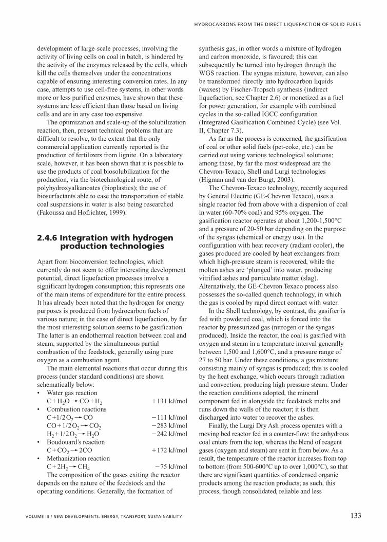
development of large-scale processes, involving theactivity of living cells on coal in batch, is hindered bythe activity of the enzymes released by the cells, whichkill the cells themselves under the concentrationscapable of ensuring interesting conversion rates. In anycase, attempts to use cell-free systems, in other wordsmore or less purified enzymes, have shown that thesesystems are less efficient than those based on livingcells and are in any case too expensive.
The optimization and scale-up of the solubilizationreaction, then, present technical problems that aredifficult to resolve, to the extent that the onlycommercial application currently reported is theproduction of fertilizers from lignite. On a laboratoryscale, however, it has been shown that it is possible touse the products of coal biosolubilization for theproduction, via the biotechnological route, ofpolyhydroxyalkanoates (bioplastics); the use ofbiosurfactants able to ease the transportation of stablecoal suspensions in water is also being researched(Fakoussa and Hofrichter, 1999).
2.4.6 Integration with hydrogenproduction technologies
Apart from bioconversion technologies, whichcurrently do not seem to offer interesting developmentpotential, direct liquefaction processes involve asignificant hydrogen consumption; this represents oneof the main items of expenditure for the entire process.It has already been noted that the hydrogen for energypurposes is produced from hydrocarbon fuels ofvarious nature; in the case of direct liquefaction, by farthe most interesting solution seems to be gasification.The latter is an endothermal reaction between coal andsteam, supported by the simultaneous partialcombustion of the feedstock, generally using pureoxygen as a combustion agent.
The main elemental reactions that occur during thisprocess (under standard conditions) are shownschematically below:• Water gas reaction
C + H2O�� CO + H2 �131 kJ/mol• Combustion reactions
C +1/2O2�� CO �111 kJ/molCO + 1/2O2�� CO2 �283 kJ/molH2+ 1/2O2�� H2O �242 kJ/mol
• Boudouard’s reactionC + CO2�� 2CO �172 kJ/mol
• Methanization reactionC + 2H2�� CH4 �75 kJ/molThe composition of the gases exiting the reactor
depends on the nature of the feedstock and theoperating conditions. Generally, the formation of
synthesis gas, in other words a mixture of hydrogenand carbon monoxide, is favoured; this cansubsequently be turned into hydrogen through theWGS reaction. The syngas mixture, however, can alsobe transformed directly into hydrocarbon liquids(waxes) by Fischer-Tropsch synthesis (indirectliquefaction, see Chapter 2.6) or monetized as a fuelfor power generation, for example with combinedcycles in the so-called IGCC configuration(Integrated Gasification Combined Cycle) (see Vol.II, Chapter 7.3).
As far as the process is concerned, the gasificationof coal or other solid fuels (pet-coke, etc.) can becarried out using various technological solutions;among these, by far the most widespread are theChevron-Texaco, Shell and Lurgi technologies(Higman and van der Burgt, 2003).
The Chevron-Texaco technology, recently acquiredby General Electric (GE-Chevron Texaco), uses asingle reactor fed from above with a dispersion of coalin water (60-70% coal) and 95% oxygen. Thegasification reactor operates at about 1,200-1,500°Cand a pressure of 20-50 bar depending on the purposeof the syngas (chemical or energy use). In theconfiguration with heat recovery (radiant cooler), thegases produced are cooled by heat exchangers fromwhich high-pressure steam is recovered, while themolten ashes are ‘plunged’ into water, producingvitrified ashes and particulate matter (slag).Alternatively, the GE-Chevron Texaco process alsopossesses the so-called quench technology, in whichthe gas is cooled by rapid direct contact with water.
In the Shell technology, by contrast, the gasifier isfed with powdered coal, which is forced into thereactor by pressurized gas (nitrogen or the syngasproduced). Inside the reactor, the coal is gasified withoxygen and steam in a temperature interval generallybetween 1,500 and 1,600°C, and a pressure range of27 to 50 bar. Under these conditions, a gas mixtureconsisting mainly of syngas is produced; this is cooledby the heat exchange, which occurs through radiationand convection, producing high pressure steam. Underthe reaction conditions adopted, the mineralcomponent fed in alongside the feedstock melts andruns down the walls of the reactor; it is thendischarged into water to recover the ashes.
Finally, the Lurgi Dry Ash process operates with amoving bed reactor fed in a counter-flow: the anhydrouscoal enters from the top, whereas the blend of reagentgases (oxygen and steam) are sent in from below. As aresult, the temperature of the reactor increases from topto bottom (from 500-600°C up to over 1,000°C), so thatthere are significant quantities of condensed organicproducts among the reaction products; as such, thisprocess, though consolidated, reliable and less
133VOLUME III / NEW DEVELOPMENTS: ENERGY, TRANSPORT, SUSTAINABILITY
HYDROCARBONS FROM THE DIRECT LIQUEFACTION OF SOLID FUELS

expensive in terms of oxygen consumption, is notparticularly suited to the production of hydrogen.
2.4.7 Process economics and development potentialof the technology
The enormous efforts made, from the post-war periodonwards, in over 50 years of R&D, have enabledsignificant improvements to the direct coalliquefaction processes, leading to a gradual decrease inthe costs of producing syncrude. DOE data show that,using the same evaluation bases (Coal Illinois n. 6,50,000 bbl/d capacity plants, identical economichypotheses), today’s direct coal liquefaction plants maybe able to produce synthetic crudes at a cost less thanhalf that which could be obtained with first generationEDS-type plants (Burke et al., 2001; Fig. 14).
This achievement can be attributed largely toresearch on the chemistry of the reaction, which hasmade it possible to propose more effective processschemes, able to increase overall conversion yields bymore than 30% (extremely important for capitalintensive technologies such as those under discussion),in addition to improving the distillates selectivity asopposed to hydrocarbon gases, with a resultingreduction in hydrogen consumption (another factorwith a significant impact on the costs of the process).Furthermore, the enormous amount of work carriedout on numerous pilot and demonstration plants hasmade it possible to improve many other aspects of thetechnology, especially as concerns the solid-liquidseparation of the products, and to overcome specificproblems presented by the process, such as the erosionof valves or corrosion in the distillation columns dueto the presence of high concentrations of acidcompounds.
Despite this, the production of synfuel from coalremains a complex technology with extremely highspecific investment costs (above 60,000 $/bpsd),especially if it is desired to guarantee acceptableenvironmental standards. However, industrialinitiatives (see Section 2.4.2) show that using thebest available technologies it may be possible, atleast on a local level, to invest in these processes,which present the enormous advantage ofdissociating a country’s economic development fromthe uncertainties associated with oil supply.Considering that the R/P (Reserves/Production) ratiofor conventional crude oil and natural gas isgenerally estimated to be 40 and 60 yearsrespectively, it is reasonable to predict that recourseto alternative fossil fuels will play an increasinglyimportant role, due in part to technological advanceswhich have made it possible to significantly reducethe costs of transformation into syncrude. Amongthese sources, alongside heavy oils, tar sands etc., itis reasonable to suppose that also coal (i.e. the mostabundant fossil fuel with an R/P of over 200 years)may contribute to supplying the international energymarket with additional quantities of liquidhydrocarbons through direct or indirect liquefactiontechnologies.
It is important to remember that the first ofthese two approaches presents advantages from anenvironmental point of view, linked to improvedenergy efficiency (70% as opposed to the 55% ofthe indirect approach), in other words lower CO2
emissions per barrel of syncrude produced.Furthermore, coal syncrudes can be transportedusing existing infrastructure, mainly controlled bythe petroleum industry, thus simplifyingmarketing. Rather than being refined at theproduction site, the synthetic crude could be sentdirectly to the refinery and treated in blends withtraditional crudes without compromising thereliability of classic refinery unit operations.There are also a series of potential synergiesbetween liquefaction plants and the refinery,linked to the production of hydrogen, themanagement of by-products etc., which maycontribute to lowering the cost of producingdistillates from coal.
References
Aldridge C.L., Bearden R. jr. (1978) US Patent 4066530to Exxon Research Engineering.
Alpert S.B., Wolk R.H. (1981) Liquefaction processes, in:Elliott M.A. (edited by) Chemistry of coal utilization, 2nd
supplementary volume, New York-Chichester, John Wiley,1919-1990.
134 ENCYCLOPAEDIA OF HYDROCARBONS
HYDROCARBONS FROM NON-CONVENTIONAL AND ALTERNATIVE FOSSIL RESOURCES
requ
ired
sel
ling
pri
ce (
$/bb
l)
0
20
40
60
80
100
1st generationprocesses
H-coal ITSL CMSL
Fig. 14. Economic comparison of direct coal liquefactionprocesses (Burke et al., 2001).

Bergius F., Billiwiller J. (1919) German Patent DE 301231.Burke F.P. et al. (2001) Summary report of the DOE direct
liquefaction process development campaign of the late 20th
Century. Topical report, DOE/PC 93054-94, July.Byskov L.S. et al. (2000) Molecular aspects of the H2 activation
on MoS2 based catalysts. The role of dynamic surfacearrangements, «Journal of Molecular Catalysis A.Chemical», 163, 117-122.
Chauvel A., Lefebvre G. (1989) Petrochemical processes.Technical and economic characteristics, Houston (TX),Gulf, 2v.; v.I: Synthesis gas derivatives and majorhydrocarbons.
Cohen M.S., Gabriele P.D. (1982) Degradation of coal bythe Fungi Polyporus Versicolor and Poria Monticola,«Applied and Environamental Microbiology», 44, 23-27.
Comolli A.G. et al. (1999) The Shenhua coal direct liquefactionplant, «Fuel Processing Technology», 59, 207-215.
Delbianco A. et al. (1995) Upgrading heavy oil using slurryprocessing, «CHEMTECH», November, 35-43.
Derbyshire F.J. (1988) Catalysis in coal liquefaction. Newdirections for research, London, IEA Coal Research.
Derbyshire F.J. et al. (1986) Temperature-staged catalyticcoal liquefaction, «Fuel», 65, 1233-1239.
Derouane G. (2000) Atomic-scale structure of HDS catalysts,«Cattech», 4, 104-106.
Fakoussa R.M. (1981) Kohle als Substract für Mikroorganismen.Untersuchungen zur mikrobiellen Umsetzung nativenSteinkhole, PhD Thesis, Bonn Universität.
Fakoussa R.M., Hofrichter M. (1999) Minireview:microbiology and biotechnology of coal degradation,«Applied Microbiology and Biotechnology», 52, 25-40.
Fraenkel D. et al. (1991) Liquefaction of coal under mildconditions. Catalysis by strong acids, iodine and theircombination, «Fuel», 70, 64-73.
Franklin J.L. (1997) Coal mining reference book, Lexington(KY), Kentucky Mining Institute.
Gorin E. (1981) Fundamentals of coal liquefaction, in: ElliottM.A. (edited by) Chemistry of coal utilization, 2nd
supplementary volume, New York-Chichester, John Wiley,1845-1918.
Harwell Laboratory (1999) Coal liquefaction, London,Department of trade and industry.
Higman C., Burgt M. van der (2003) Gasification, Burlington(MA), Gulf; Amsterdam, Elsevier.
IEA (International Energy Agency) (2001) World EnergyOutlook 2001, Paris, Organization for EconomicCooperation and Development/IEA.
McMillen D.F. et al. (1987) Mechanisms of hydrogen transferand bond scission of strongly bonded coal structures indonor-solvent systems, «Fuel», 66, 1611-1620.
Mishra S.K. , Klimpel R.R. (1987) Fine coal processing, ParkRidge (NJ), Noyes.
Montanari R. et al. (2003) Upgrading petroleum residueswith EST technology, in: Proceedings of the 17 th WorldPetroleum Congress, Rio de Janeiro, 1-5 September 2002.
Neavel R.C. (1976) Liquefaction of coal in hydrogen-donorand non-donor vehicles, «Fuel», 55, 237-242.
Ross D.S. (1984) Coal conversion in carbon monoxide andwater systems, in: Gorbaty M.L. et al., Coal science, NewYork, Academic Press, 1982-1984, 3v.; v. III, 301-338.
Schlosberg R.H. (edited by) (1985) Chemistry of coalconversion, New York-London, Plenum Press.
Shinn J.H. (1984) From coal to single-stage and two-stageproducts. A reactive model of coal structure, «Fuel», 63,1187-1196.
Stach E. et al. (1982) Stach’s textbook of coal petrology, Berlin-Stuttgart, Gebrüder Borntraeger.
Sullivan F.R. (editor) (1981) Upgrading coal liquids.Proceedings of the 179th meeting of the American ChemicalSociety, Houston (TX), 24-25 March 1980.
Wasaka S. et al. (2003) The influence of hydrodynamics onthe NEDOL coal liquefaction reaction, «Energy & Fuels»,17, 412-418.
Alberto DelbiancoEniTecnologie
San Donato Milanese, Milano, Italy
135VOLUME III / NEW DEVELOPMENTS: ENERGY, TRANSPORT, SUSTAINABILITY
HYDROCARBONS FROM THE DIRECT LIQUEFACTION OF SOLID FUELS
