250 gb 1403 ok layout 1 - home - transfluid · for connection with a transfluid fluid coupling. ......
TRANSCRIPT
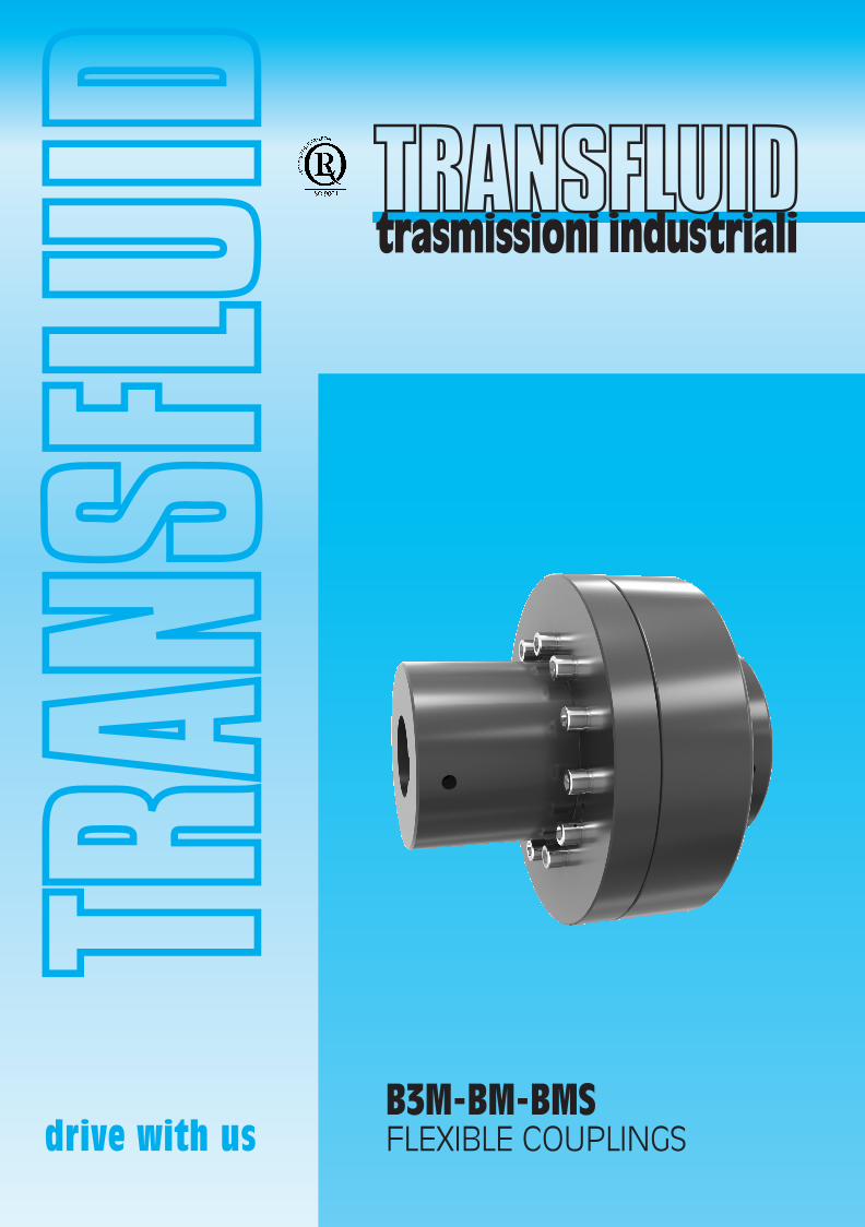
B3M-BM-BMSFLEXIBLE COUPLINGS
250 GB 1403 ok_Layout 1 23/06/15 13:16 Pagina 1

GENERAL DESCRIPTION
1Flexible couplings - 1506
With decades of experience and thousands of applications onTRANSFLUID fluid couplings the BT flexible coupling line hasbeen expanded to include couplings for shaft-to-shaftapplication. The new series has been studied to provide anexceptionally robust coupling with excellent misalignmentcapabilities and easy installation and assembly. TheB3M/BM/BMS couplings high quality flexible elements providereliable performance while protecting the coupled machines.
The B3M/BM/BMS require minimal maintenance except for aperiodical inspection and replacement of the rubber elements.To simplify in this check, especially in alignment free drives, theB3M was developed. This version allows for inspection andremoval of the rubber elements while preserving alignment.
Manufactured with the highest quality materials inTRANSFLUID's factory in Gallarate Italy the new B3M/BM/BMSseries is available in 17 different sizes with torque capabilityexceeding 33100Nm (24,494 lbs-ft)
ADVANTAGES:– Compensation of misalignments– Shocks and vibrations damping– Fail - safe and capable of withstanding high overloads – Quick and easy change of flexible elements– Maintenance free
B3M B3MBP
BM BMS
250 GB 1403 ok_Layout 1 23/06/15 13:16 Pagina 2

2Flexible couplings - 1506
Shaft couplings
Standard version for connecting two shafts. The B3M allowschanging of flexible elements with no need for axial movementof either of the couplings hubs.
Brake drum couplings
With brake drum.See Catalogue 355 for TRANSFLUID BRAKES.
Brake disc couplings
With brake disc.See Catalogue 355 for TRANSFLUID BRAKES.
Spacer couplings
B3M with removable spacer.
Combination
For connection with a TRANSFLUID fluid coupling.
ATEX VERSIONSIt is possible to get BM series couplings, with finished bores, certified as equipment for intended use in hazardous zones accordingto directive 94/9/EC (ATEX).
Certification can be provided for the following categories:x II 3 G/D c T4 Surface (Non-mining) applicationx II 2 G/D c T4 Surface (Non-mining) applicationx I M2 c T4 Mining application
In case of inquiry for ATEX products, you have to apply providing the application form TF6735 duly filled up.
333
GENERAL DESCRIPTION
250 GB 1403 ok_Layout 1 23/06/15 13:16 Pagina 3

TECHNICAL DATA
3Flexible couplings - 1506
Couplingsize
Max. (*)Nmax
(rpm)
Nominal torqueTKN
Maximum torqueTKmax
Dynamic torsional stiffnessCTdyn
Technical data for standard rubber elements
Tab. 1
01 20 15 40 30 2000 1480 5000 02 55 41 110 81 3000 2220 5000 05 75 56 150 111 5200 3848 5000 10 160 118 320 237 14800 10952 5000 20 320 237 640 474 25100 18574 5000 40 630 466 1260 932 63000 46620 4000 43 630 466 1260 932 41800 30932 4000 45 940 696 1880 1391 82200 60828 3600 48 1480 1095 2960 2190 90700 67118 3600 50 2060 1524 4120 3049 209700 155178 3000 53 2060 1524 4120 3049 106600 78884 3000 55 3160 2338 6320 4677 187400 138676 3000 60 5220 3863 10440 7726 412400 305176 2200 70 7650 5661 15300 11322 627600 464424 2000 80 11550 8547 23100 17094 936100 692714 1800 90 21030 15562 42060 31124 971400 718836 1800 95 33100 24494 66200 48988 1956000 1447440 1500
Tab. 2-2A Selection based on max allowable bore of the flexible coupling, assuming value 1 for all factors (Sm, St, Sz, SAtex). For applications where thefactors are different from 1, the coupling must be properly selected according to selection procedure at page 4
(Nm) (lbs-ft) (Nm) (lbs-ft) (Nm/rad) (lbs-ft/rad)
SizeShaft dia.
(mm)
Shaft lenght(mm)
Power(kW)
Torque(Nm)
Couplingsize
Motor power at 1500 rpm
Motor
56 9
20
0.06 0.4 01 0.09 0.57 01
63 11
23 0.12 0.76 01
0.18 1.15 01
71 14
30 0.25 1.60 01
0.37 2.5 01
80 19
40 0.55 3.50 01
0.75 4.50 01 90S 24 50 1.1 7.00 02 90L 24 50 1.5 10.00 02
100L 28
60 2.2 14.00 02
3 19.00 02 112M 28 60 4 25.50 02 132S 38 80 5.5 35.00 10 132M 38 80 7.5 48.00 10 160M 42 110 11 70.00 10 160L 42 110 15 95.50 10 180M 48 110 18.5 118.00 20 180L 48 110 22 140.00 20 200L 55 110 30 191.00 20 225S 60 140 37 235.50 20 225M 60 140 45 286.50 20 250M 65 140 55 350.00 40 280S 75 140 75 477.50 48 280M 75 140 90 573.00 48 315S 80 170 110 700.00 48
315M 80
170 132 840.50 48
160 1020.00 48 355S 100 210 250 1595.00 60 355M 100 210 315 2005.00 60
SizeShaft dia.
(inch)
Shaft lenght(inch)
Power(hp)
Torque(lbs-ft)
Couplingsize
Motor power at 1800 rpmMotor
143T 0.875 2.250 1 2.92 02
145T 0.875
2.250 1.5 4.38 02
2 5.84 02 182T 1.125 2.750 3 8.75 02 184T 1.125 2.750 5 14.59 02 213T 1.375 3.375 7.5 21.88 10 215T 1.375 3.375 10 29.18 10 254T 1.625 4.000 15 43.77 10 256T 1.625 4.000 20 58.36 10 284T 1.875 4.625 25 72.95 20 286T 1.875 4.625 30 87.54 20 324T 2.125 5.250 40 116.71 20 326T 2.125 5.250 50 145.89 20 364T 2.375 5.875 60 175.07 40 365T 2.375 5.875 75 218.84 40 405T 2.875 7.250 100 291.78 48 444T 3.375 8.500 125 364.73 60 445T 3.375 8.500 150 437.68 60 447T 3.375 8.500 200 583.57 60 447T 3.375 8.500 250 729.46 60 449T 3.375 8.500 300 875.35 60
Tab. 2 - IEC electric motors Tab. 2A - NEMA electric motors*Referred to standard materials
250 GB 1403 ok_Layout 1 23/06/15 13:16 Pagina 4

COUPLING SIZE SELECTION
4Flexible couplings - 1506
The coupling must be selected so that the operating conditionsof the coupling, do not exceed the maximum allowable load ofthe coupling itself. For driving machines not generating cyclictorque loads the selection of the coupling can be performedusing the driving torque and the corresponding service factor.When the driving machine generates cyclic torque loads (e.g.internal combustion engines) the selection of the coupling mustbe checked by a torsional analysis of the complete system.Steps to be followed are as follows.
1) Using the power and rotational speed, calculate the torque ofthe driving machine TAN:
where:P = power of driving machine (kW) - n = rotational speed ofdriving machine (rpm)TAN = torque of driving machine (Nm)
2) Once the torque of the driving machine TAN has beencalculated, determine the service factor and check that thetorque of the driving machine times the service factor,temperature factor and starting factor is lower than thecharacteristic torque of the chosen coupling TKN:
where:TKN = characteristic torque of the chosen coupling (Nm) Sm = service factor from Tab. 4 and Tab. 6St = temperature factor from Tab. 3Sz = starting factor from Tab. 5SAtex = 1,2 in case of use in hazardous zones acc. to 94/9/EC(Atex). In normal zones, SAtex = 1
Load classifications and service factors of Tab. 6 are referred toturbines and hydraulic or electric motor as the prime mover. Ifthe prime mover is a single or multi cylinder engine, the servicefactor from Tab. 6 must be replaced by its corresponding valuefrom Tab. 4
3) Known the maximum possible torque during operation Tmax,check that the maximum torque times the temperature factor islower than the maximum characteristic torque of the chosencoupling TKmax:
Calculation example
1) Application dataA torsionally elastic coupling type BM installed between anelectric motor and a rotary pump gear type.Power of the electric motor: P = 160 kWRotational speed: n = 1490 rpm2) Calculation of driving torque TAN
The driving torque TAN of the driving machine is:
3) Check of the nominal TKN
From Tab. 6 the service factor corresponding to the drivenmachine load classification is: Sm = 1.5. Because the primemover is an electric motor, it is not necessary to use conversionTab. 4From Tab. 3 for an ambient temperature of 40 °C, thetemperature factor is: St = 1.1From Tab. 5 for starting frequency per hour of 60 the startingfactor is: Sz = 1.1The nominal torque TKN of the driving machine is:
4) Selection of the couplingFrom Tab. 1, with torque values TKN > = 1861 Nm the choice isfor coupling size BM 50.
5) As final selection step, check compatibility betweenequipment shaft and max allowable bore of selected coupling
TAN = 9550 x P / n
TKN >= TAN x Sm x St x Sz x SAtex
TKmax >= Tmax x St
TAN = 9550 x 160 / 1490 = 1025 Nm
TKN >= 1025 Nm x 1.5 x 1.1 x 1.1 = 1861 Nm
-40 °C +40 °C +60 °C +80 °C >+80 °C +30 °C
-40° F +104°F +140 °F +176 °F >+176 °F +86° F
Ambienttemperature
St 1.0 1.1 1.4 1.8 on
request
30 60 120 240 >240
Starting frequency per hour
Sz 1.0 1.1 1.2 1.3 on
request
Tab. 3 - Temperature factor
Tab. 5 - Starting factor
Steam and gas turbines, Single cylinder Multi-cylinder hydraulic or electric engines engines motors (from Tab. 6)
1.00 1.50 1.25 1.25 1.75 1.50 1.50 2.00 1.75 1.75 2.25 2.00 2.00 2.50 2.25 2.25 2.75 2.50 2.50 3.00 2.75
Tab. 4Conversion table for single or multi-cylinder engines
250 GB 1403 ok_Layout 1 23/06/15 13:16 Pagina 5

LOAD CLASSIFICATION AND SERVICE FACTOR
5Flexible couplings - 1506
Tab. 6 - Service factor for steam turbines, hydraulic or electric motors, as prime mover
Agitators Pure liquids 1.00 Liquids and solids 1.25 Blowers Centrifugal 1.00 Lobe 1.50 Vane 1.25 Car dumpers 2.50 Car pullers - intermittent duty 1.50 Chemical industry Agitators 1.75 Centrifuges (heavy) 1.75 Centrifuges (light-weight) 1.25 Cooling drums 1.75 Drying drums 1.75 Mixers 1.75
Compressors Centrifugal 1.25 Lobe 1.50 Reciprocating -multi-cylinder 2.00 Conveyors - uniform loaded Belt 1.00 Bucket 1.25 Chain 1.25 Screw 1.25 Conveyors - Not uniformly loaded Belt 1.25 Bucket 1.50 Chain 1.50 Reciprocating 2.50 Screw 1.50 Table 2.00 Cranes and hoists Main hoists 2.00 Trolley drive 1.75 Bridge drive 1.75 Slope 1.50 Crushers - Grinders 2.75 Dredges Bucket conveyors 1.50 Cable reels 1.75 Cutter heads 2.25 Maneuvering winches 1.75 Pumps 1.75 Screen drive 1.75 Slewing gears 2.00 Elevators Bucket 1.75 Freight 2.00 Gravity discharge 1.50 Fans Centrifugal 1.00 Cooling towers 2.00 Forced draft 1.50 Induced draft w/o damper control 2.00
Feeders Belt 1.25 Reciprocating 2.50 Screw 1.25 Food industry Beet slicer 1.75 Filling machines 1.00 Cereal cooker 1.25 Dough mixer 1.75 Meat grinders 1.75 Bottling, can filling machine 1.00 Generators, transformers Frequency transformers 2.00 Generators 2.00 Welding generators 2.00 Laundries Washing machines 2.00
Lumber industry Barkers - drum type 2.00 Live rolls 2.00 Log haul 2.00 Off bearing rolls 2.00 Slab conveyor 1.50 Sorting table 1.50 Trimmer feed 1.75 Machine tools Bending roll 2.00 Punch press - gear driven 2.00 Tapping machines 2.50 Other machine tools: Main drives 1.50 Auxiliary drives 1.25 Metal rolling mills Billet shears 2.25 Chain transfers 1.50 Cold rolling mills 2.25 Continuous casting plants 2.00 Ingot handling machinery 2.25 Ingot pushers 2.25 Manipulators 2.25 Roller adjustment drivers 2.00 Roller straighteners 2.00 Sheet mills 2.25 Trimming shears 2.00 Tube welding machines 2.25 Winding machines (strip and wire) 2.00 Wire drawing benches 2.25 Mixers Concrete mixers 1.75 Drum type 1.50 Oil industry Chillers 1.25 Oil pipeline pumps 1.75 Rotary drilling equipment 2.00
Paper industry Barker 2.00 Barking drum (spur gear only) 2.25 Beater & pulper 1.75 Bleacher 1.00 Calenders 2.00 Couch 1.75 Cutters. platers 2.00 Cylinders 1.75 Dryers 1.75 Felt stretcher 1.25 Felt whipper 2.00 Log haul 2.00 Suction roll 1.75 Washers and thickeners 1.50 Wet presses 2.00 Winders 1.50 Printing presses 1.50 Pullers 2.00 Pumps Centrifugal 1.00 Reciprocating 2.00 Rotary - gear, lobe, vane 1.50 Rubber calender industry Calender 2.00 Mixer - Banbury 2.50 Rubber mill 2.25 Sheeter 2.00 Tire building machines 2.50 Tire & tube press openers 1.00 Tubers and strainers 2.00 Screens Air washing 1.00 Rotary - stone or gravel 1.50 Travel water intake 1.25 Sewage disposal equipment 1.25 Stone and clay working machines Ball mills 2.25 Beater mills 2.25 Breakers 2.25 Brick presses 2.25 Hammer mills 2.25 Rotary kilns 2.00 Tube mills 2.00 Textile machines Batchers 1.50 Looms 1.50 Printing and dyeing machines 1,50 Tanning vats 1.50 Water treatment Aerators 1.00 Screw pumps 1.50 Wood working machines Debarking drums 2.00 Planing machines 1.50 Wood chippers 2.75
250 GB 1403 ok_Layout 1 23/06/15 13:16 Pagina 6
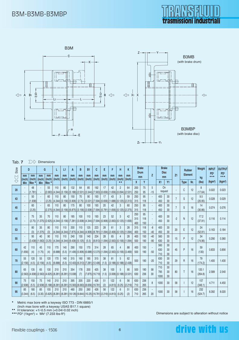
B3M-B3MB-B3MBP
6Flexible couplings - 1506
• Metric max bore with a keyway ISO 773 - DIN 6885/1(Inch max bore with a keyway USAS B17.1 square)
•• H tolerance: +1/-0.5 mm (+0.04/-0.02 inch)••• PD2 (1kgm2) = Wk2 (7.233 lbs-ft2) Dimensions are subject to alteration without notice
Tab. 7
------
--
----
42(1.656)
55(2.156)
65(2.563)
75(2.938)
85(3.344)
20
43
45
48
53
55
60
70
80
90
95
48(1.781)
50(1.938)
60(2.25)
75(2.75)
80(3)95
(3.438)
110(4)
120(4.5)
135(4.938)
150(5.5)180(6.5)
-----
35(1.375)
35(1.375)
40(1.563)
45(1.75)
55(2.156)
65(2.563)
75(2.938)
85(3.35)
55(2.063)
60(2.25)
65(2.375)
70(2.625)
80(3)90
(3.25)
110(4)
120(4.5)
130(4.625)
140(5.188)
155(5.625)
110(4.344)
110(4.344)
110(4.344)
110(4.344)
110(4.344)
110(4.344)
170(6.688)
170(6.688)
210(8.281)
210(8.281)
210(8.281)
80(3.156)
80(3.156)
80(3.156)
80(3.156)
110(4.344)
110(4.344)
140(5.5)
140(5.5)
210(8.281)
210(8.281)
210(8.281)
132(5.188)
150(5.906)
175(6.875)
185(7.281)
200(7.875)
240(9.438)
290(11.406)
315(12.403)
354(13.938)
395(15.563)
460(18.126)
64(2.531)
70(2.75)
80(3.156)
100(3.938)
110(4.344)
130(5.125)
150(5.906)
160(6.313)
178(7)
205(8.063)
250(9.844)
85(3.344)
90(3.531)
100(3.938)
110(4.344)
125(4.906)
140(5.5)
170(6.688)
185(7.281)
200(7.875)
220(8.656)
260(10.25)
192(7.563)
193(7.594)
193(7.594)
193(7.594)
223(8.781)
224(8.813)
314(12.375)
315(12.406)
425(16.719)
426(16.781)
426(16.781)
17(0.656)
17(0.656)
20(0.781)
23(0.906)
28(1.094)
28(1.094)
28(1.094)
38(1.5)
38(1.5)
51(2)56
(2.219)
42(1.656)
43(1.688)
42(1.656)
52(2.063)
61(2.406)
65(2.563)
65(2.563)
81(3.188)
100(3.938)
122(4.813)
122(4.813)
2(0.094)
3(0.125)
3(0.125)
3(0.125)
3(0.125)
4(0.156)
4(0.156)
5(0.188)
5(0.188)
6(0.25)
6(0.25)
64(2.531)
59(2.313)
60(2.375)
42(1.656)
28(1.094)
28(1.094)
88(3.469)
62(2.438)
90(3.531)
56(2.219)
51(2)
200250250315250315250315400315400400500
400500
500
500630
630710630710
7595951189511895118150118150150190
150190
190
190236
236265236265
5-15
-------
-8-40-40-90
--50
-20
5830
8
-20
400450400450
400450
400450560630560630710630710710795
1000
1000
1000
30303030
3030
303030303030303030303030
30
30
-
7
7
-2
20
15
45
29
80
58
58
C
S
S
N
E
P
P
R
T
I
I
12
12
16
12
12
12
16
16
16
12
16
8(17.64)
9.5(20.95)
14(30.86)
17.2(37.91)
24(52.91)
34(74.96)
59(130)
79(174.2)
120.1(264.8)
157(346.1)
232(524.7)
0.022
0.028
0.074
0.116
0.163
0.290
0.833
1.400
2.589
4.711
8.392
0.023
0.029
0.076
0.114
0.184
0.360
0.856
1.430
2.540
4.450
8.020
D
mm(inch)Min
mm (inch)Max •
mm(inch)Min
mm (inch)Max •
G BrakeDrummm
X Y
BrakeDiscmm
Onrequest
X1 Y1
RubberElement
Weight
kg(lbs)
INPUTPD2
•••(kgm2)
OUTPUTPD2
•••(kgm2)Type Nr.
Z Z1
L L1 A B B1 C E F H K
mm mm mm mm mm mm mm mm mm mm (inch) (inch) (inch) (inch) (inch) (inch) (inch) (inch) (inch) (inch) ••
Siz
e
Dimensions
B3MB
B3MBP
B3M
(with brake drum)
(with brake disc)
250 GB 1403 ok_Layout 1 23/06/15 13:16 Pagina 7
BM-BMB-BMBP
7Flexible couplings - 1506
• Metric max bore with a keyway ISO 773 - DIN 6885/1 (Inch max bore with a keyway USAS B17.1 square)•• H tolerance: +1 /-0.5 mm (+0.04/-0.02 inch)••• PD2 (1kgm2) = Wk2 (7.233 lbs-ft2) Dimensions are subject to alteration without notice
Tab. 8
------------
40(1.563)
40(1.563)
35(1.375)
45(1.75)
65(2.563)
75(2.938)
85(3.344)
85(3.344)
01
02
05
10
20
40
45
48
50
55
60
70
80
90
19(0.75)
28(1.125)
32(1.25)
42(1.656)
60(2.25)
80(3)70
(2.625)
80(3)
90(3.25)
90(3.25)
110(4)
120(4.5)
130(4.625)
140(5.188)
--------------
35(1.375)
35(1.375)
40(1.563)
45(1.75)
55(2.156)
65(2.563)
75(2.938)
19(0.75)
25(1)32
(1.25)42
(1.656)55
(2.063)80(3)65
(2.375)
70(2.625)
90(3.25)
90(3.25)
110(4)
120(4.5)
130(4.625)
140(5.188)
35(1.375)
40(1.563)
50(1.969)
60(2.375)
110(4.344)
110(4.344)
110(4.344)
110(4.344)
140(5.51)140
(5.51)
170(6.688)
170(6.688)
210(8.281)
210(8.281)
35(1.375)
40(1.563)
50(1.969)
60(2.375)
80(3.156)
110(4.344)
80(3.156)
80(3.156)
110(4.344)
110(4.344)
140(5.5)
140(5.5)
210(8.281)
210(8.281)
62(2.438)
73(2.875)
86(3.375)
110(4.344)
132(5.188)
170(6.688)
175(6.875)
185(7.281)
250(9.844)
240(9.438)
290(11.406)
315(12.406)
354(13.938)
395(15.563)
35(1.375)
45(1.781)
55(2.156)
70(2.75)
90(3.531)
120(4.719)
110(4.344)
120(4.719)
140(5.5)150
(5.906)
170(6.688)
185(7.281)
200(7.875)
220(8.656)
35(1.375)
45(1.781)
55(2.156)
70(2.75)
85(3.344)
120(4.719)
100(3.938)
110(4.344)
135(5.313)
140(5.5)
170(6.688)
185(7.281)
200(7.875)
220(8.656)
72(2.844)
82(3.219)
102(4.031)
122(4.813)
192(7.563)
223(8.781)
193(7.594)
193(7.594)
253(9.96)254(10)
314(12.375)
315(12.406)
425(16.719)
426(16.781)
8(0.313)
9(0.344)
11(0.438)
11(0.438)
14(0.551)
25(0.969)
17(0.656)
22(0.875)
30(1.188)
27(1.063)
27(1.063)
33(1.313)
36(1.406)
51(2)
25(0.969)
27(1.063)
30(1.188)
33(1.313)
42(1.656)
45(1.781)
42(1.656)
52(2.063)
65(2.563)
65(2.563)
65(2.563)
81(3.188)
100(3.938)
122(4.813)
2(0.094)
2(0.094)
2(0.094)
2(0.094)
2(0.094)
3(0.125)
3(0.125)
3(0.125)
3(0.125)
4(0.156)
4(0.156)
5(0.188)
5(0.188)
6(0.250)
160200200250250315250315250315400315400400500
400500
500
500630
630710
60757595951189511895118150118150150190
150190
190
190236
236265
-
-
-
--155
-1515-8--
15--
-8-40-40-90
--50
-20
5882
60-
395450400450
400450
400450560630560630710630710710795
1000
1000
30303030
3030
303030303030303030303030
30
-
-
-
-
-
35
7
-2
15
15
45
29
80
58
A
A
B
B
C
C
S
N
D
P
P
R
T
I
8
8
8
12
12
16
16
12
16
12
16
16
16
12
0.8(1.76)
1.4(3.86)
2.3(5.07)
4.3(9.5)10.1
(22.26)22
(48.5)17
(37.5)
19(41.9)
34(74.9)
38(83.8)
60(132.2)
80(176.2)
108(238.1)
171(377)
0.007
0.011
0.023
0.081
0.021
0.082
0.079
0.117
0.182
0.290
0.790
1.310
2.480
4.777
0.007
0.004
0.027
0.009
0.023
0.064
0.076
0.114
0.470
0.360
0.856
1.430
2.540
4.777
D
mm(inch)Min
mm (inch)Max •
mm(inch)Min
mm (inch)Max •
G BrakeDrummm
X Y
BrakeDiscmm
Onrequest
Onrequest
Onrequest
Onrequest
Onrequest
Onrequest
X1 Y1
RubberElement
Weight
kg(lbs)
INPUTPD2
•••(kgm2)
OUTPUTPD2
•••(kgm2)Type Nr.
Z Z1
L L1 A B B1 C E F H
mm mm mm mm mm mm mm mm mm (inch) (inch) (inch) (inch) (inch) (inch) (inch) (inch) (inch) ••
BMB
BMBP
BM
(with brake drum)
(with brake disc)
Siz
e
Dimensions
250 GB 1403 ok_Layout 1 23/06/15 13:16 Pagina 8
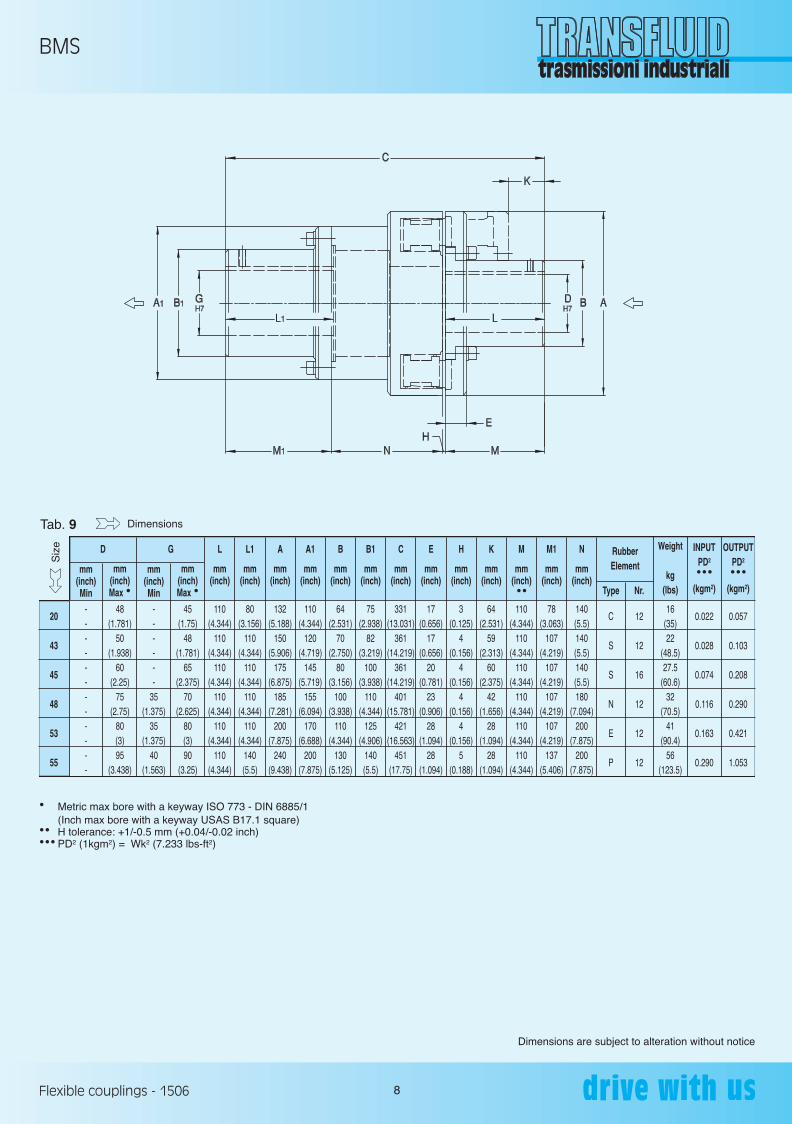
BMS
8Flexible couplings - 1506
• Metric max bore with a keyway ISO 773 - DIN 6885/1 (Inch max bore with a keyway USAS B17.1 square)•• H tolerance: +1/-0.5 mm (+0.04/-0.02 inch)••• PD2 (1kgm2) = Wk2 (7.233 lbs-ft2)
Dimensions are subject to alteration without notice
Tab. 9
------------
20
43
45
48
53
55
48(1.781)
50(1.938)
60(2.25)
75(2.75)
80(3)95
(3.438)
------
35(1.375)
35(1.375)
40(1.563)
45(1.75)
48(1.781)
65(2.375)
70(2.625)
80(3)90
(3.25)
110(4.344)
110(4.344)
110(4.344)
110(4.344)
110(4.344)
110(4.344)
80(3.156)
110(4.344)
110(4.344)
110(4.344)
110(4.344)
140(5.5)
132(5.188)
150(5.906)
175(6.875)
185(7.281)
200(7.875)
240(9.438)
110(4.344)
120(4.719)
145(5.719)
155(6.094)
170(6.688)
200(7.875)
64(2.531)
70(2.750)
80(3.156)
100(3.938)
110(4.344)
130(5.125)
75(2.938)
82(3.219)
100(3.938)
110(4.344)
125(4.906)
140(5.5)
331(13.031)
361(14.219)
361(14.219)
401(15.781)
421(16.563)
451(17.75)
17(0.656)
17(0.656)
20(0.781)
23(0.906)
28(1.094)
28(1.094)
3(0.125)
4(0.156)
4(0.156)
4(0.156)
4(0.156)
5(0.188)
64(2.531)
59(2.313)
60(2.375)
42(1.656)
28(1.094)
28(1.094)
110(4.344)
110(4.344)
110(4.344)
110(4.344)
110(4.344)
110(4.344)
78(3.063)
107(4.219)
107(4.219)
107(4.219)
107(4.219)
137(5.406)
140(5.5)140(5.5)140(5.5)180
(7.094)200
(7.875)200
(7.875)
C
S
S
N
E
P
12
12
16
12
12
12
16(35)22
(48.5)27.5
(60.6)32
(70.5)41
(90.4)56
(123.5)
0.022
0.028
0.074
0.116
0.163
0.290
0.057
0.103
0.208
0.290
0.421
1.053
D
mm(inch)Min
mm (inch)Max •
mm(inch)Min
mm (inch)Max •
G RubberElement
Weight
kg(lbs)
INPUTPD2
•••(kgm2)
OUTPUTPD2
•••(kgm2)Type Nr.
L L1 A A1 B B1 C E H K M M1 N
mm mm mm mm mm mm mm mm mm mm mm mm mm (inch) (inch) (inch) (inch) (inch) (inch) (inch) (inch) (inch) (inch) (inch) (inch) (inch) ••
Siz
e
Dimensions
250 GB 1403 ok_Layout 1 23/06/15 13:16 Pagina 9
INSTALLATION AND MAINTENANCE
9Flexible couplings - 1506
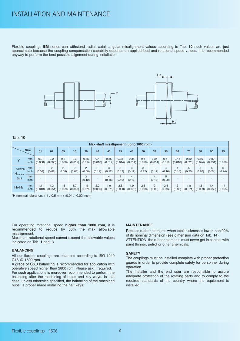
Size 01 02 05 10 20 40 43 45 48 50 53 55 60 70 80 90 95
0.2 0.2 0.2 0.3 0.35 0.4 0.35 0.35 0.35 0.5 0.35 0.41 0.45 0.50 0.60 0.80 1 (0.008) (0.008) (0.008) (0.012) (0.014) (0.016) (0.014) (0.014) (0.014) (0.020) (0.014) (0.016) (0.018) (0.020) (0.024) (0.031) (0.039)Y mm
(inch)
2 2 2 2 2 3 3 3 3 3 3 4 4 5 5 6 6 (0.08) (0.08) (0.08) (0.08) (0.08) (0.12) (0.12) (0.12) (0.12) (0.12) (0.12) (0.16) (0.16) (0.20) (0.20) (0.24) (0.24)
mm(inch)
Max shaft misalignment (up to 1800 rpm)
Tab. 10
Flexible couplings BM series can withstand radial, axial, angular misalignment values according to Tab. 10; such values are justapproximate because the coupling compensation capability depends on applied load and rotational speed values. It is recommendedanyway to perform the best possible alignment during installation.
Y
H1
H2
For operating rotational speed higher than 1800 rpm, it isrecommended to reduce by 50% the max allowablemisalignment.Maximum rotational speed cannot exceed the allowable valuesindicated on Tab. 1 pag. 3.
BALANCINGAll our flexible couplings are balanced according to ISO 1940G16 @ 1500 rpm. A grade of G6,3 balancing is recommended for application withoperative speed higher than 2800 rpm. Please ask if required. For such applications is moreover recommended to perform thebalancing after the machining of holes and key ways. In thatcase, unless otherwise specified, the balancing of the machinedhubs, is proper made installing the half keys.
MAINTENANCE
Replace rubber elements when total thickness is lower than 90%of its nominal dimension (see dimension data on Tab. 14).ATTENTION: the rubber elements must never get in contact withpaint thinner, petrol or other chemicals.
SAFETYThe couplings must be installed complete with proper protectionguards in order to provide complete safety for personnel duringoperation. The installer and the end user are responsible to assureadequate protection of the rotating parts and to comply to therequired standards of the country where the equipment isinstalled.
- - - - 3 - 4 4 4 - 4 5 - - - - - (0.12) (0.16) (0.16) (0.16) (0.16) (0.20)
mm(inch)
1.1 1.3 1.5 1.7 1.9 2.2 1.9 2.3 1.9 2.5 2 2.4 2 1.8 1.5 1.4 1.4 (0.043) (0.051) (0.059) (0.067) (0.075) (0.086) (0.075) (0.090) (0.075) (0.098) (0.08) (0.094) (0.08) (0.071) (0.059) (0.055) (0.055)H1-H2
mm(inch)
B3M/BM
BMS
*Hnominal
*H nominal tolerance: + 1 /-0.5 mm (+0.04 / -0.02 inch)
250 GB 1403 ok_Layout 1 23/06/15 13:16 Pagina 10
INSTALLATION AND MAINTENANCE
10Flexible couplings - 1506
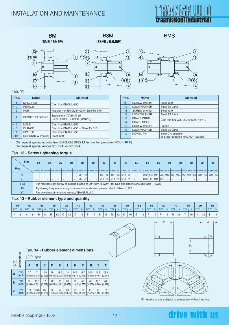
Pos. Name Material
• 1 MALE HUB Cast Iron EN-GJL-250 • 2 FEMALE 3 HUB Nodular Iron EN-GJS-400 or Steel Fe 510 •• 4 RUBBER ELEMENT
Special mix 70°Sh(A) ±5 [-40°C (-40°F); +120°C (+248°F)]
• 5 MALE Cast Iron EN-GJL-250 • 6 FLANGE Cast Iron EN-GJL-250 or Steel Fe 510 • 7 SPACER Cast Iron EN-GJL-250 8-8a SET SCREW (metric) Steel 12.9
Tab. 11
Pos. Name Material
9 SCREW (metric) Steel 12.9 10 LOCK WASHER Steel SS 2343 11 SCREW (metric) Steel 12.9 12 LOCK WASHER Steel SS 2343 • 13 BRAKE DRUM Cast iron EN-GJL-250 or Steel Fe 510 • 14 BRAKE DISC 15 SCREW (metric) Steel 8.8 16 LOCK WASHER Steel SS 2343 17 DOWEL PIN Steel C72 (elastic) or Steel hardened HRC 60±2 (parallel)
• On request special nodular Iron EN-GJS-350-22 LT for low temperature -40°C (-40°F)•• On request special rubber 60°Sh(A) or 80°Sh(A)
Pos.SCREW Nm
- - - - - - - - - - M6 18 M6 18 - - M12 143 M14 228 M10 85 M12 143 M14 228 M24 1170 M24 1170 M8 42 M10 85
- - - - - - - - - - M8 42 M10 85 - - M10 85 M12 143 - - - - - - - - - - M10 85 M10 85
SCREW Nm SCREW Nm SCREW Nm SCREW Nm SCREW Nm SCREW Nm SCREW Nm SCREW Nm SCREW Nm SCREW Nm SCREW Nm SCREW Nm SCREW Nm SCREW Nm SCREW Nm SCREW Nm
9
11
8-8a
15
17
For max bore set screw should be placed at 90° from keyway - for type and dimensions see table TF5726
Tightening torque according to screw size and class, please refer to table N 1152
For dowel pin dimensions contact TRANSFLUID
Tab. 12 - Screw tightening torque
a mm(inch)
b
c
mm(inch)
mm(inch)
A B C D E I N P R S T
6.7 7 10.9 16 19.6 35 14.7 19.7 20.5 11.8 23.9(0.264) (0.275) (0.429) (0.630) (0.772) (1.378) (0.579) (0.775) (0.807) (0.464) (0.941)
10 13.5 17 22 30 68 29 40 40 19,5 49(0.394) (0.531) (0.669) (0.866) (1.181) (2.677) (1.142) (1.575) (1.575) (0.768) (1.929)
14.5 18.25 25 39 50 98 39 49 64 30 74(0.571) (0.719) (0.984) (1.535) (1.968) (3.858) (1.535) (1.929) (2.520) (1.181) (2.913)
Tab. 14 - Rubber element dimensions
Type
Dim
ensi
ons
Size 01 02 05 10 20 40 43 45 48 50 53 55 60 70 80 90 95
Dimensions are subject to alteration without notice
c
b
a
TYPE Nr. TYPE Nr. TYPE Nr. TYPE Nr. TYPE Nr. TYPE Nr. TYPE Nr. TYPE Nr. TYPE Nr. TYPE Nr. TYPE Nr. TYPE Nr. TYPE Nr. TYPE Nr. TYPE Nr. TYPE Nr. TYPE Nr.
A 8 A 8 B 8 B 12 C 12 C 16 S 12 S 16 N 12 D 16 E 12 P 12 P 16 R 16 T 16 I 12 I 16
01 02 05 10 20 40 43 45 48 50 53 55 60 70 80 90 95
Tab. 13 - Rubber element type and quantity
250 GB 1403 ok_Layout 1 23/06/15 13:16 Pagina 11
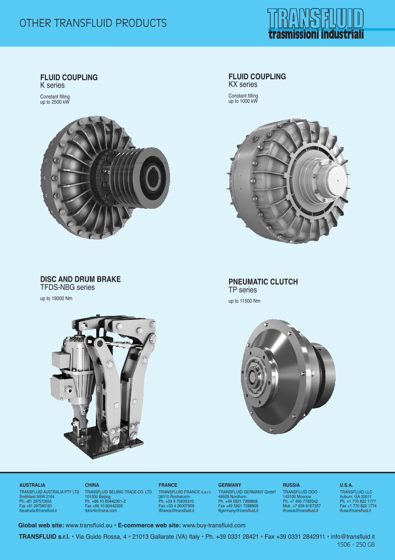
FLUID COUPLINGK seriesConstant fillingup to 2500 kW
FLUID COUPLINGKX seriesConstant fillingup to 1000 kW
DISC AND DRUM BRAKETFDS-NBG seriesup to 19000 Nm
PNEUMATIC CLUTCHTP seriesup to 11500 Nm
OTHER TRANSFLUID PRODUCTS
TRANSFLUID s.r.l. • Via Guido Rossa, 4 • 21013 Gallarate (VA) Italy • Ph. +39 0331 28421 • Fax +39 0331 2842911 • [email protected] - 250 GB
AUSTRALIATRANSFLUID AUSTRALIA PTY LTDSmithfield NSW 2164Ph. +61 297572655Fax +61 [email protected]
FRANCETRANSFLUID FRANCE s.a.r.l.38110 RochetoirinPh. +33 9 75635310Fax +33 4 [email protected]
RUSSIATRANSFLUID OOO143100 MoscowPh. +7 495 7782042Mob. +7 926 [email protected]
U.S.A.TRANSFLUID LLC Auburn, GA 30011Ph. +1 770 822 1777Fax +1 770 822 [email protected]
GERMANYTRANSFLUID GERMANY GmbH48529 NordhornPh. +49 5921 7288808 Fax +49 5921 [email protected]
CHINATRANSFLUID BEIJING TRADE CO. LTD101300 BeijingPh. +86 10 60442301-2Fax +86 10 [email protected]
Global web site: www.transfluid.eu • E-commerce web site: www.buy-transfluid.com
250 GB 1403 ok_Layout 1 23/06/15 13:16 Pagina 12