#27379 v1 - slope stability - bcit commons · slope stability analysis, design and construction...
TRANSCRIPT

WPC #27379 07/09
AMRC 2011 MODULE 7
Slope Stability
CONTENTS Objectives ........................................................................................ 7-1 Procedures ....................................................................................... 7-1 7.1 Introduction ........................................................................... 7-3 7.2 Landslide Processes .............................................................. 7-5 7.3 Factors Determining Slope Safety and Types of Failure ...... 7-9 7.4 Slope Stability Assessment and Methods of
Improving Stability ............................................................. 7-15 7.4.1 Slopes in Free Draining Soils ................................ 7-15 7.4.2 Slopes in Clays ...................................................... 7-16 7.4.3 Slopes in Cemented Soils ...................................... 7-17 7.4.4 Remedial Methods for a Failing Slope .................. 7-17
7.5 Slopes in Rock .................................................................... 7-21 7.6 Side Hill Fill ....................................................................... 7-23 7.7 Self-Test .............................................................................. 7-25


WPC #27379 07/09 AMRC 2011 7-1
Module 7
Slope Stability
Objectives Upon successful completion of this module, you will be able to:
identify and define the terms related to slope stability and safety describe the factors determining slope stability in soils and rock recognize the situations in the field that may indicate a
potentially unstable slope describe methods used to improve slope stability for a variety of
soil materials.
Procedures Study the module materials and make notes as required. Perform the self-test on these principles and review the course
materials in such a manner as to be able to successfully complete similar questions upon examination.

MODULE 7 Slope Stability
WPC #27379 07/09 7-2 AMRC 2011

WPC #27379 07/09 AMRC 2011 7-3
SECTION 7.1
Introduction
An economically designed slope should be made as steep as possible while maintaining an adequate margin of safety against failure. For earth dam slopes, this safety margin has to be well defined because failure could be catastrophic. For road slopes (cut and fill), a lesser margin of safety is normally used. The reasons for the use of a lower safety margin are: The results of a slope failure are not normally critical. You’re normally dealing with long lengths of side slope (i.e.,
cut or fill slopes) and changes in side slope rate affect the quantities and the price significantly.
Thorough exploratory investigations and design work make it possible to reasonably estimate just how steep a slope can be while still remaining safe. However, such studies are quite expensive and have to be started and completed before construction can begin. Often, in order to avoid delays to start up of a project, only those areas which appear to be sensitive or involve high volume cut or fill (hence high cost) are studied in detail. Typically, decisions as to the soil cut and fill slopes, treatment of rock slopes, etc. are made based on soil classification and past experience under similar conditions. If an exceptional slope stability problem arises, then special studies have to be made. In British Columbia, with its wide range of terrain and soil conditions, almost every slope problem imaginable is to be met. This may range from a very weak clay on an extremely flat slope which moves slowly year by year, to a massive granite, which stands vertical and where slope failure is sudden and dramatic.

MODULE 7 Slope Stability
WPC #27379 07/09 7-4 AMRC 2011
WPC #27379 07/09 AMRC 2011 7-5
SECTION 7.2
Landslide Processes
The following section is taken from the publication A Guide for Management of Landslide-Prone Terrain in the Pacific Northwest and is considered as Figure 7.1 for this module. As described in Module 1, there are six dominant groups of landslide processes commonly occurring on forested terrain: A. falls B. creep C. slumps and earthflows D. debris avalanches and debris flows E. debris torrents F. bedrock failures. The following adds to the explanation in Module 1.
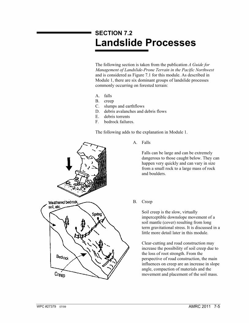
A. Falls
Falls can be large and can be extremely dangerous to those caught below. They can happen very quickly and can vary in size from a small rock to a large mass of rock and boulders.
B. Creep
Soil creep is the slow, virtually imperceptible downslope movement of a soil mantle (cover) resulting from long term gravitational stress. It is discussed in a little more detail later in this module.
Clear-cutting and road construction may increase the possibility of soil creep due to the loss of root strength. From the perspective of road construction, the main influences on creep are an increase in slope angle, compaction of materials and the movement and placement of the soil mass.
MODULE 7 Slope Stability
WPC #27379 07/09 7-6 AMRC 2011
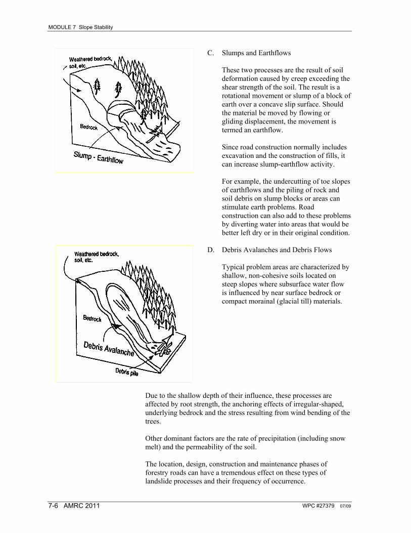
C. Slumps and Earthflows
These two processes are the result of soil deformation caused by creep exceeding the shear strength of the soil. The result is a rotational movement or slump of a block of earth over a concave slip surface. Should the material be moved by flowing or gliding displacement, the movement is termed an earthflow.
Since road construction normally includes excavation and the construction of fills, it can increase slump-earthflow activity.
For example, the undercutting of toe slopes of earthflows and the piling of rock and soil debris on slump blocks or areas can stimulate earth problems. Road construction can also add to these problems by diverting water into areas that would be better left dry or in their original condition.
D. Debris Avalanches and Debris Flows
Typical problem areas are characterized by shallow, non-cohesive soils located on steep slopes where subsurface water flow is influenced by near surface bedrock or compact morainal (glacial till) materials.
Due to the shallow depth of their influence, these processes are affected by root strength, the anchoring effects of irregular-shaped, underlying bedrock and the stress resulting from wind bending of the trees. Other dominant factors are the rate of precipitation (including snow melt) and the permeability of the soil. The location, design, construction and maintenance phases of forestry roads can have a tremendous effect on these types of landslide processes and their frequency of occurrence.

MODULE 7 Slope Stability
WPC #27379 07/09 AMRC 2011 7-7
E. Debris Torrents
Debris torrents are usually confined to areas with steep, intermittent drainage paths (ravines, gullies, etc.). During periods of high discharge, any material that has been previously deposited in that drainage path (e.g., from the occurrence of sideslope slides) may be picked up by the flowing water and the material transported down the path at high speed. When the, torrent loses momentum (normally at the point where the channel widens and hence the velocity drops) the suspended material is deposited.
Road building and timber harvesting activities disturb the soil and make it more erodible. Also, by the logging of the timber in these operations, they end up producing a mixture of loose soil, roots, branches, etc. During periods of heavy runoff this becomes a good supply of debris, which in turn increases the opportunity for debris torrents.
Road construction can also cause an increase in peak discharge by concentrating surface flow into these drainage paths. Combined with this, temporary dams may be formed due to the buildup of debris and these can cause disastrous situations when they fail. Numerous examples of these are evident in BC — possibly the most notorious of these are along the Squamish highway.
F. Bedrock Failures
Bedrock slumps and bedrock slides were described in Module 1.

MODULE 7 Slope Stability
WPC #27379 07/09 7-8 AMRC 2011
WPC #27379 07/09 AMRC 2011 7-9
SECTION 7.3
Factors Determining Slope Safety and Types of Failure
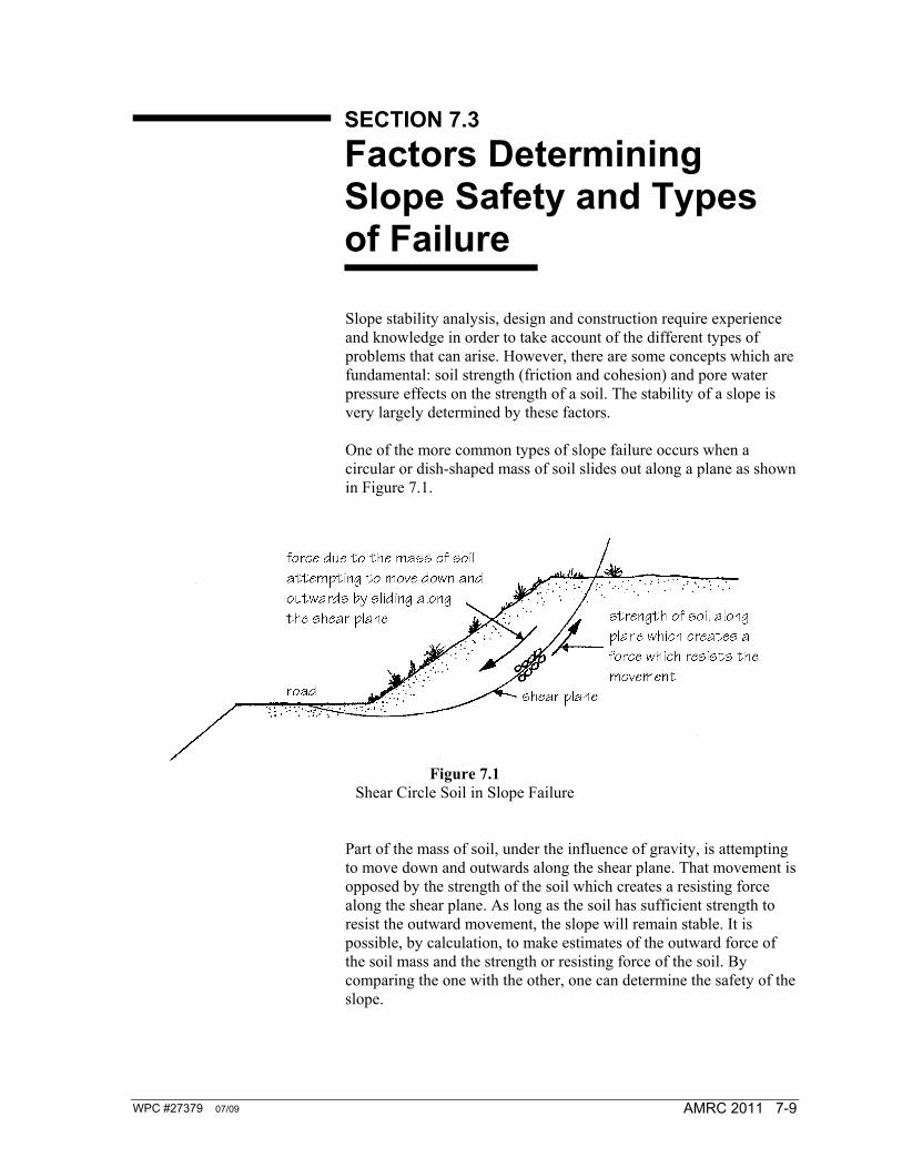
Slope stability analysis, design and construction require experience and knowledge in order to take account of the different types of problems that can arise. However, there are some concepts which are fundamental: soil strength (friction and cohesion) and pore water pressure effects on the strength of a soil. The stability of a slope is very largely determined by these factors. One of the more common types of slope failure occurs when a circular or dish-shaped mass of soil slides out along a plane as shown in Figure 7.1.
Figure 7.1
Shear Circle Soil in Slope Failure Part of the mass of soil, under the influence of gravity, is attempting to move down and outwards along the shear plane. That movement is opposed by the strength of the soil which creates a resisting force along the shear plane. As long as the soil has sufficient strength to resist the outward movement, the slope will remain stable. It is possible, by calculation, to make estimates of the outward force of the soil mass and the strength or resisting force of the soil. By comparing the one with the other, one can determine the safety of the slope.
MODULE 7 Slope Stability
WPC #27379 07/09 7-10 AMRC 2011
There are several complications involved with these calculations: A. The strength of the soil (cohesion, c, and angle of internal
friction, Φ) must be found. B. The actual shear plane along which the soil might fail cannot be
directly determined. It has to be found by the analysis of the many circles in order to find the most critical one; this becomes the assumed failure plane.
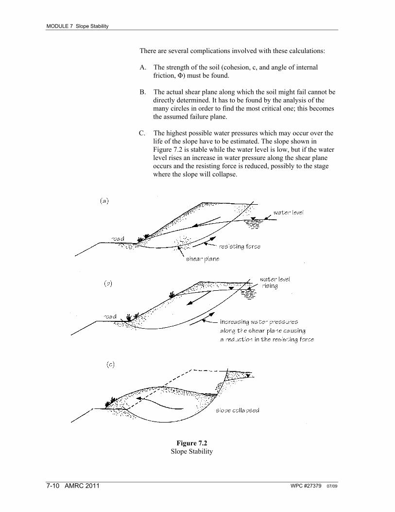
C. The highest possible water pressures which may occur over the
life of the slope have to be estimated. The slope shown in Figure 7.2 is stable while the water level is low, but if the water level rises an increase in water pressure along the shear plane occurs and the resisting force is reduced, possibly to the stage where the slope will collapse.
Figure 7.2 Slope Stability
MODULE 7 Slope Stability
WPC #27379 07/09 AMRC 2011 7-11
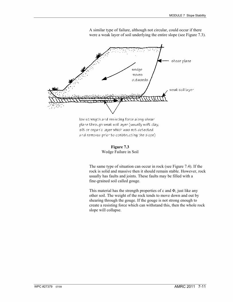
A similar type of failure, although not circular, could occur if there were a weak layer of soil underlying the entire slope (see Figure 7.3).
Figure 7.3 Wedge Failure in Soil
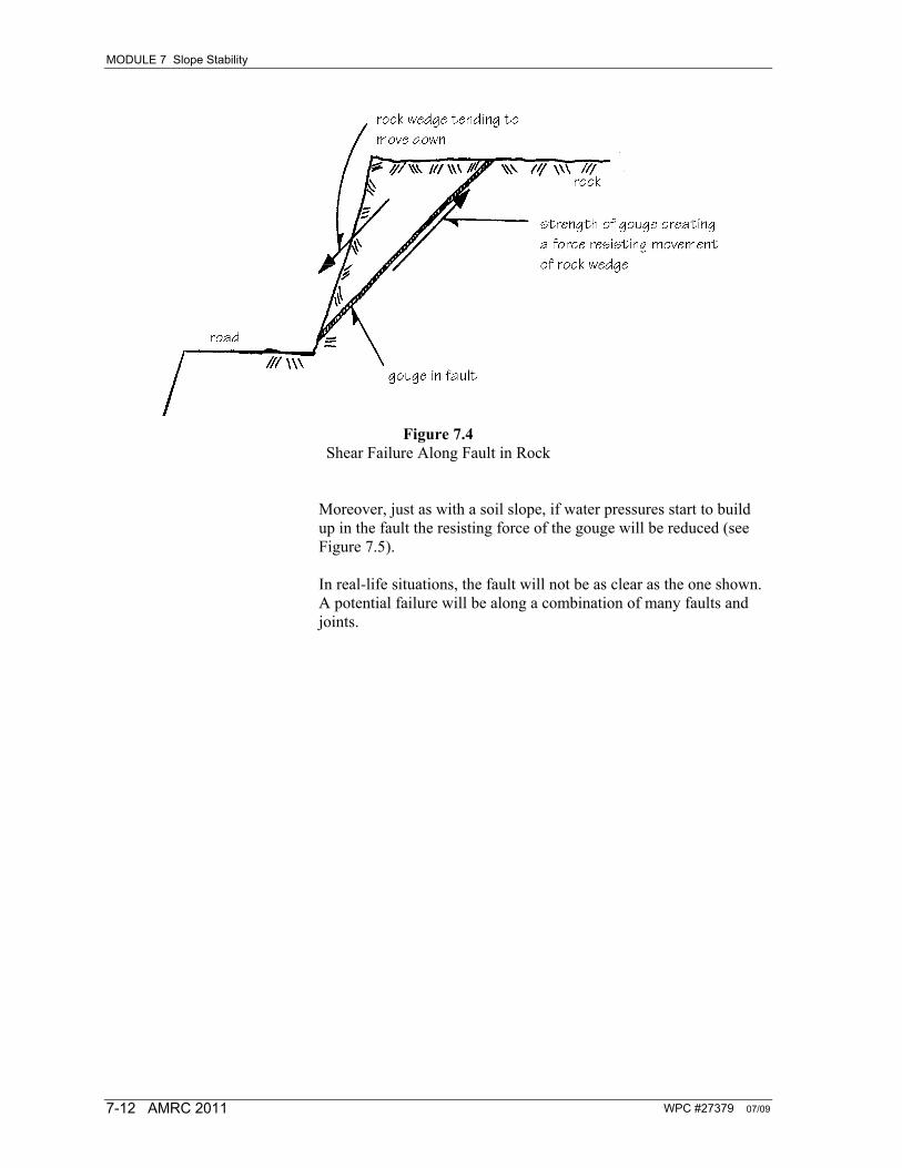
The same type of situation can occur in rock (see Figure 7.4). If the rock is solid and massive then it should remain stable. However, rock usually has faults and joints. These faults may be filled with a fine-grained soil called gouge. This material has the strength properties of c and Φ, just like any other soil. The weight of the rock tends to move down and out by shearing through the gouge. If the gouge is not strong enough to create a resisting force which can withstand this, then the whole rock slope will collapse.
MODULE 7 Slope Stability
WPC #27379 07/09 7-12 AMRC 2011
Figure 7.4
Shear Failure Along Fault in Rock Moreover, just as with a soil slope, if water pressures start to build up in the fault the resisting force of the gouge will be reduced (see Figure 7.5). In real-life situations, the fault will not be as clear as the one shown. A potential failure will be along a combination of many faults and joints.
MODULE 7 Slope Stability
WPC #27379 07/09 AMRC 2011 7-13
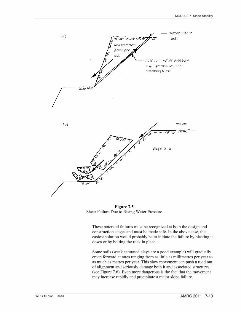
Figure 7.5 Shear Failure Due to Rising Water Pressure
These potential failures must be recognized at both the design and construction stages and must be made safe. In the above case, the easiest solution would probably be to initiate the failure by blasting it down or by bolting the rock in place. Some soils (weak saturated clays are a good example) will gradually creep forward at rates ranging from as little as millimetres per year to as much as metres per year. This slow movement can push a road out of alignment and seriously damage both it and associated structures (see Figure 7.6). Even more dangerous is the fact that the movement may increase rapidly and precipitate a major slope failure.

MODULE 7 Slope Stability
WPC #27379 07/09 7-14 AMRC 2011
Figure 7.6 Creeping Slope
WPC #27379 07/09 AMRC 2011 7-15
SECTION 7.4
Slope Stability Assessment and Methods of Improving Stability
Any slope in soil or rock should be considered as a separate and unique problem. Although there are some general assessments which can be made, these do not in any way supersede the uniqueness of the problem.
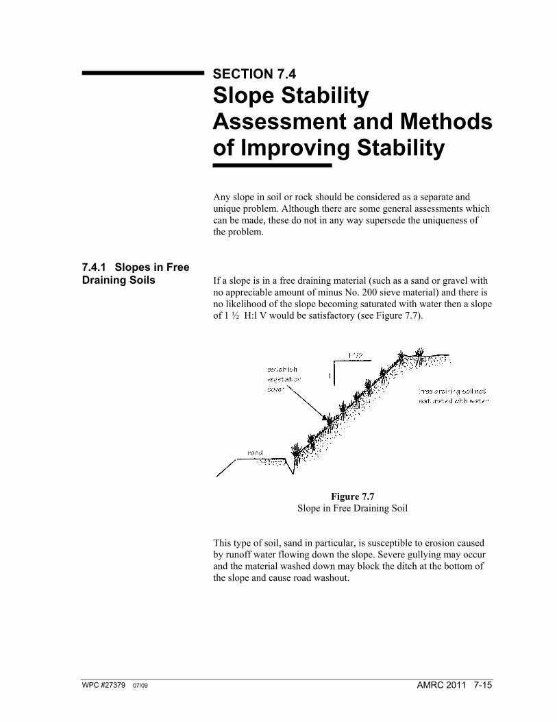
7.4.1 Slopes in Free Draining Soils If a slope is in a free draining material (such as a sand or gravel with
no appreciable amount of minus No. 200 sieve material) and there is no likelihood of the slope becoming saturated with water then a slope of 1 ½ H:l V would be satisfactory (see Figure 7.7).
Figure 7.7 Slope in Free Draining Soil
This type of soil, sand in particular, is susceptible to erosion caused by runoff water flowing down the slope. Severe gullying may occur and the material washed down may block the ditch at the bottom of the slope and cause road washout.
MODULE 7 Slope Stability
WPC #27379 07/09 7-16 AMRC 2011
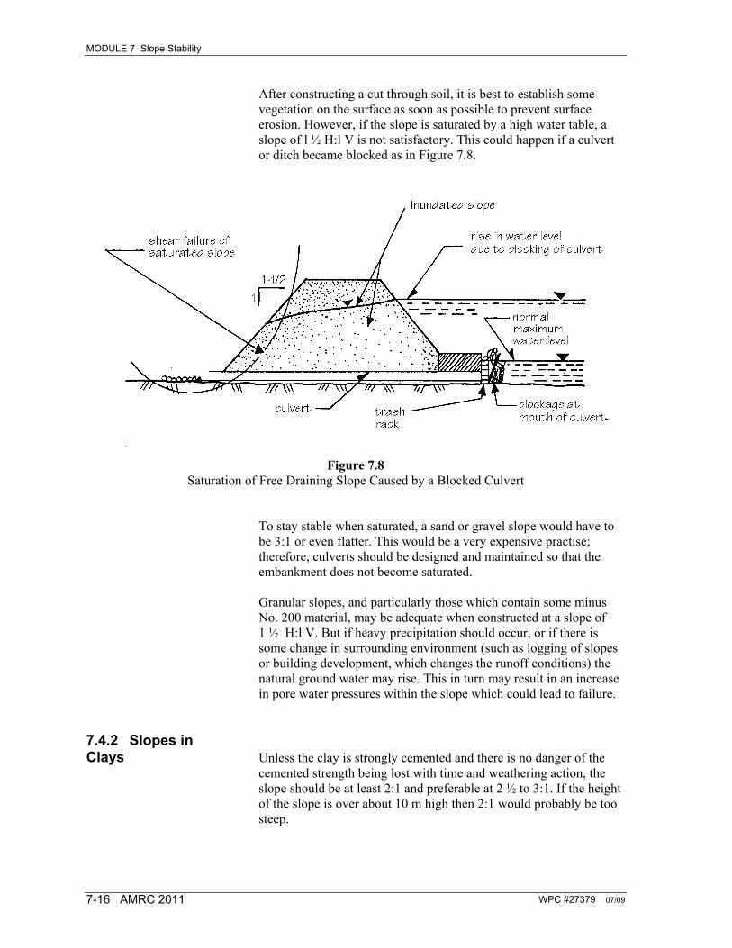
After constructing a cut through soil, it is best to establish some vegetation on the surface as soon as possible to prevent surface erosion. However, if the slope is saturated by a high water table, a slope of l ½ H:l V is not satisfactory. This could happen if a culvert or ditch became blocked as in Figure 7.8.
Figure 7.8
Saturation of Free Draining Slope Caused by a Blocked Culvert To stay stable when saturated, a sand or gravel slope would have to be 3:1 or even flatter. This would be a very expensive practise; therefore, culverts should be designed and maintained so that the embankment does not become saturated. Granular slopes, and particularly those which contain some minus No. 200 material, may be adequate when constructed at a slope of 1 ½ H:l V. But if heavy precipitation should occur, or if there is some change in surrounding environment (such as logging of slopes or building development, which changes the runoff conditions) the natural ground water may rise. This in turn may result in an increase in pore water pressures within the slope which could lead to failure.
7.4.2 Slopes in Clays Unless the clay is strongly cemented and there is no danger of the
cemented strength being lost with time and weathering action, the slope should be at least 2:1 and preferable at 2 ½ to 3:1. If the height of the slope is over about 10 m high then 2:1 would probably be too steep.

MODULE 7 Slope Stability
WPC #27379 07/09 AMRC 2011 7-17
7.4.3 Slopes in Cemented Soils If the soil is strongly cemented it can probably be cut at a steep
slope, 1:1 or even steeper. A steep slope may be acceptable, provided that the cementing action is strong and that it can be ascertained that there will be no dramatic loss in cementing strength if subjected to weathering. Even with a strong cementing action, pieces of soil may well drop off and create a hazard to the road below or plug the ditch with debris and cause a washout.
7.4.4 Remedial Methods for a Failing Slope If a slope is showing signs of failure, such as tension cracks, then it
should be examined by a suitably qualified person. If the condition is not too serious it may be possible to restabilize it. In an extreme case this may not be possible and the slope would have to be demolished and rebuilt. Any method by which the water pressures can be reduced will do much to increase the stability. Some may be fairly simple; for instance, the cleaning out of existing ditches or the construction of new ones to prevent or intercept water approaching the slope may be all that is needed (see Figure 7.9).
Figure 7.9 Surface Ditch to Prevent Water Approaching the Slope
and thus Avoid an Increase in Water Pressure Another technique for relieving the water pressure in an existing slope in order to restabilize it is to insert horizontal perforated drainpipes which enable the water to drain out at a faster rate. In consequence, the water table is lowered and the pore water pressure reduced. This is a relatively inexpensive procedure (see Figure 7.10).

MODULE 7 Slope Stability
WPC #27379 07/09 7-18 AMRC 2011
Figure 7.10 Pipes to Relieve Water Pressure in an Existing Highway Slope
This method has been used extensively and successfully by the BC Ministry of Transportation, in both soil and rock slopes. The perforated drainpipes do require maintenance (such as periodic flushing out) to prevent blockage by the buildup of fine-grained soil in the pipes. If there is sufficient space, a mass of soil at the toe might stabilize the slope (see Figure 7.11). This material should be free draining; clean, strong rockfill would be ideal. A better solution would be to place a layer of sand and gravel between the existing slope and the rockfill. This would serve as a filter to prevent an inwash of soil particles into the toe fill. Inwash, if not prevented, may clog the fill and lead to a buildup of water pressure, once more.
Figure 7.11 Restabilizing a Slope by Adding Free Draining Fill at the Toe
If suitable materials for fill are not within economic hauling distance, random material for the toe fill (called a berm) may be used. However, if this is done, a free draining layer is placed behind and under the berm (see Figure 7.12).

MODULE 7 Slope Stability
WPC #27379 07/09 AMRC 2011 7-19
Figure 7.12 Random Fill to Restabilize a Slope

MODULE 7 Slope Stability
WPC #27379 07/09 7-20 AMRC 2011

WPC #27379 07/09 AMRC 2011 7-21
SECTION 7.5
Slopes in Rock
If the rock is strong, solid and massive it will stand vertically. However, the surface normally suffers some damage caused by the blasting of rock and any loose pieces of rock should be pried free while the road is being built. This process is called scaling (see Figure 7.13).
Figure 7.13 Slope in Sound Rock
In some special cases, the actual design slope of the rock face should be determined only when the rock mass has been thoroughly investigated by means of a mapping program. This mapping should describe all the factors affecting the stability: joint and fault spacing and orientation; consistency; degree of weathering; ground water, etc. The current practice of the Ministry of Transportation and Highways is to cut rock slopes vertically or at a slope to suit the jointing. They also check scale all slopes. Joints and faults cause many problems since the orientation of the joints has a significant effect on safety. If the jointing is not serious then the rock face may be stabilized by rock anchors (see Figure 7.14).

MODULE 7 Slope Stability
WPC #27379 07/09 7-22 AMRC 2011
Figure 7.14 Rock Anchors to Stabilize a Jointed Rock Cut
Weathering action, particularly the freezing and accompanying expansion of water in tiny cracks, works rock loose. Because of this, all rock faces require inspection regularly to check whether new pieces of rock are becoming loose and in danger of falling.
WPC #27379 07/09 AMRC 2011 7-23
SECTION 7.6
Side Hill Fill
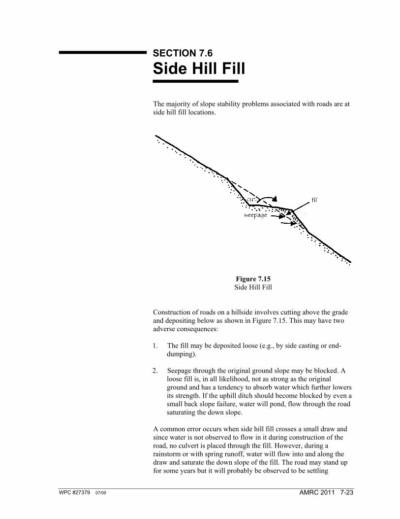
The majority of slope stability problems associated with roads are at side hill fill locations.
Figure 7.15 Side Hill Fill
Construction of roads on a hillside involves cutting above the grade and depositing below as shown in Figure 7.15. This may have two adverse consequences: 1. The fill may be deposited loose (e.g., by side casting or end-
dumping). 2. Seepage through the original ground slope may be blocked. A
loose fill is, in all likelihood, not as strong as the original ground and has a tendency to absorb water which further lowers its strength. If the uphill ditch should become blocked by even a small back slope failure, water will pond, flow through the road saturating the down slope.
A common error occurs when side hill fill crosses a small draw and since water is not observed to flow in it during construction of the road, no culvert is placed through the fill. However, during a rainstorm or with spring runoff, water will flow into and along the draw and saturate the down slope of the fill. The road may stand up for some years but it will probably be observed to be settling

MODULE 7 Slope Stability
WPC #27379 07/09 7-24 AMRC 2011
somewhat on the downhill side of the road. The normal remedy to this settlement is to top the road surface with gravel. Some time later the road may fail rapidly and dramatically, leaving a failure with an oversteepened slope. These potential trouble spots should be recognized before they fail. The usual control measure is to ensure adequate drainage of subsurface and surface water and it involves one or more of the following: maintaining ditches and culverts; installing perforated subdrains in the uphill ditch; paving ditches to prevent water flow through the road base; redirecting surface runoff prior to the road ditch (see Figure 7.16).
Figure 7.16 Control of Water Near the Road Surface

WPC #27379 07/09 AMRC 2011 7-25
SECTION 7.7
Self-Test
1. Describe/define in your own words the following terms: A. shear plane B. creep C. gouge. 2. Sketch the following: A. wedge failure in soil B. shear circle failure in soil C. stabilization of slope by means of rock fill D. rock anchors to stabilize a jointed rock cut. 3. What problems may occur in road construction due to side hill
fill? Suggest some methods of avoiding them. 4. Describe two types of mass erosional processes. 5. “Drainage isn’t really important!” Suggest reasons why this
statement is totally untrue.

MODULE 7 Slope Stability
WPC #27379 07/09 7-26 AMRC 2011