3120-n-t1- thermal circuit breaker
TRANSCRIPT

www.e-t-a.de 1
3120-N...-...T1-... Thermal Circuit Breaker
1930
1
Description
The 3120-N...-...T1-... thermal circuit breaker/switch combination unites overcurrent protection and the function of an ON/OFF switch within a single component. The trip element is a thermal bimetal. Type 3120-N...-...T1-... is ideally suited for overload protection of motors, pumps, transformers and cables. After tripping, it can reliably, easily and quickly be reset. The positively trip-free mechanism ensures reliable disconnection of the circuit even with the actuator blocked.
Type 3120-N is also available with thermal-magnetic trip. (technical data p. 19 ff).
Type 3120-N is also available as a switch in accordance IEC/EN 61058 (see data sheet switch 3120-N...Q1).
3120-N...-...T1-...
Features
l Single or double pole thermal circuit breaker/switch combinationl Voltage ratings: AC 240 V, DC 50 V (AC 415 V upon request)l Current rating range: 0.1 … 20 A (up to 30 A upon request)l Optional: push-in terminals for easy and quick wiring with a
long-term stabilityl Extendable functionality through appliance inlet modulel Functional extension options with add-on modules for low voltage
release, auxiliary contact function, remote trip or fast magnetic trip
l Maximum equipment availability is ensured by overload protection perfectly matched with the loads (prevention of nuisance tripping) and quick resettability
l Reduced mounting and wiring timel Space-saving designl Reduced disposition and storage costsl Increased overall reliability
Further information
Approvals
Compliances
The current data sheet as well as other relevant documents are available on our website: www.e-t-a.de/e016
Typical applications Your benefits
Medical and laboratory equipment, apparatus and machine construction, professional tools, household and garden appliances, offices machines, audio equipment, machine tools

www.e-t-a.de2
3120-N...-...T1-... Thermal Circuit Breaker
1930
1
Technical data Current ratings and internal resistance values
Current rating (A)
Internal resistance per pole (Ω)
Current rating (A)
Internal resistance per pole (Ω)
0.1 94 4 0.0435
0.2 24 4.5 0.0435
0.3 12 5 0.0325
0.4 5.30 6 0.0215
0.5 4.20 7 0.0165
0.6 2.90 8 0.0165
0.8 1.50 10 < 0.02
1 0.9 12 < 0.02
1.2 0.80 14 < 0.02
1.5 0.45 15 < 0.02
2 0.27 16 < 0.02
2.5 0.0785 18 < 0.02
3 0.0595 20 < 0.02
3.5 0.0565
For detailed technical information please see www.e-t-a.de/ti_d
Voltage ratings AC 240 V, DC 50 V (AC 415 V upon request)
Current rating range 0.1 ... 20 A (up to 30A upon request for single pole units)
Typical life 1-pole
AC 240 V: 0.1...20 A 30,000 operations at 1 x IN, inductiveDC 50 V: 0.1...4 A 30,000 operations at 1 x IN, inductive 4.5...16 A 30,000 operations at 1 x IN, resistiveDC 28 V: 0.1...20 A 30,000 operations at 1 x IN, inductive
Typical life 2-pole
AC 240 V: 0.1...16 A 50,000 operations at 1 x IN, inductive 17...20 A 30,000 operations at 1 x IN, inductiveDC 50 V: 0.1...16 A 50,000 operations at 1 x IN, inductive 17...20 A 50,000 operations at 1 x IN, inductive
Ambient temperature -30 … 60 °C
Insulation coordination(IEC 60664)
2.5 kV /2 reinforced insulation at operating area
Dielectric strength
Operating areapole to pole (2-pole)
test voltage AC 3,000 Vtest voltage AC 1,500 V
Insulation resistance > 100 MΩ (DC 500 V)
Rupture capacity Icn (IEC/EN 60934)
IN UN Icn
1-pole, 2-pole 0.1 ... 2 A AC 240 V / DC 50 V
10 x IN
1-pole 2.5 ... 10 A DC 50 V 50 A
1-pole 2.5 ... 20 A AC 240 V / DC 28 V
200 A
2-pole 2.5 ... 20 A DC 50 V 250 A
2-pole 2.5 ... 20 A AC 240 V / DC 28 V
300 A
Interrupting capacity Inc (UL 1077)
IN UN Inc
1-pole, 2-pole 0.1 ... 20 A AC 250 V 5,000 A, C, 1
1-pole, 2-pole 0.1 ... 20 A DC 50 V 1,000 A, C, 1
Degree of protection (IEC 60529)Operating area
Terminal area
IP40
with water splash protection IP65
IP00
with water splash protection IP64
Vibration 8 g (57-500 Hz), ± 0.61 mm (10-57 Hz)test to IEC 60068-2-6, test Fc 10 frequency cycles/axis
Shock 30 g (11 ms) test to IEC 60068-2-27, test Ea
Corrosion 96 hours at 5 % salt mist, test to IEC 60068-2-11, test Ka
Humidity 240 hrs in 95 % RH test to IEC 60068-2-78, test Cab
Mass approx. 27 g (1-pole) approx. 31 g (2-pole)approx. 42 g (2-pole with PT terminals)

www.e-t-a.de 3
3120-N...-...T1-... Thermal Circuit Breaker
1930
1
3120-N...-...T1-... Thermal Circuit Breaker
Order numbering code
Type No.3120 thermal rocker-actuated circuit breaker/switch combination Mounting method N3 snap-in, mounting cut-out 50.5 x 21.5 mm N5 snap-in, mounting cut-out 44.5 x 22 mm Number of poles 1 1-pole switching, 1-pole thermally protected 2 2-pole switching, 2-pole thermally protected 5 2-pole switching, 1-pole thermally protected Style 1 standard 3 with actuator guard 4 with water splash protection (IP65) 6 version for appliance inlet modules
X3120-A/-B (only for mounting method N5) A with actuator guard and cross-hole
(for optional interlock) Terminal design PT push-in terminals P7 blade terminals H7 as P7, terminals 11 and 21 with flat head
screws M3.5 - standard for units with undervoltage release module
N7 as P7, with additional shunt terminals 12(i) and 22(i) G7 as N7, terminals 11 and 21 with additional flat
head screws M3.5 Trip curve T1 thermal trip Actuator W rocker Rocker colour and illumination 01 . black without illumination 02 . white without illumination 04 . red without illumination 12 . Y white with illumination 14 . R red with illumination 15 . Y orange with illumination 16 . T blue with illumination 19 . G green with illumination Marking of rocker actuator rocker style A (not for style 4) D F K L X Illumination voltage range (= operating voltage) 1 DC 12 V 2 DC 24 V 3 AC 115 V 4 AC 230 V 5 DC 48 V 6 AC 400 V (for 2-pole versions
up to 16 A) Current ratings 0.1 ... 20 A
3120-N5 2 4 - PT T1-W 19 D G 4 - 16 A ordering example
A D F K L X
Order numbering code
Type No.3120 thermal circuit breaker/switch combination with push button
actuation Mounting method N3 snap-in, mounting cut-out 50.5 x 21.5 mm N5 snap-in, mounting cut-out 44.5 x 22 mm Number of poles 1 1-pole switching, 1-pole thermally protected 2 2-pole switching, 2-pole thermally protected 5 2-pole switching, 1-pole thermally protected Style D with actuator guard E with actuator guard and water splash cover F with power-on protection V with power-on protection and water splash cover Terminal design PT push-in terminals P7 blade terminals H7 as P7, terminals 11 and 21 with flat head
screws M3.5 - standard for units with undervoltage release module
N7 as P7, with additional shunt terminals 12(i) and 22(i) G7 as N7, terminals 11 and 21 with additional
flat head screws M3.5 Trip curve T1 thermal trip Actuator S two push buttons Colour of push button/illumination
(style D and F without water splash protection)
GRD green/red without illumination GRDG green with LED illumination/red
without illumination Colour of push button/illumination
(style E and V with water splash protection)
GRX green/red without illumination GRXG green with LED illumination/red
without illumination Illumination voltage range (= operating voltage) 1 DC 12 V 2 DC 24 V 3 AC 115 V 4 AC 230 V 5 DC 48 V 6 AC 400 V (for 2-pole versions
up to 16 A) Current ratings 0.1 ... 20 A
3120-N3 5 V - PT T1-S GRXG - 20 A ordering example
Please observe our minimum ordering quantities.

www.e-t-a.de4
3120-N...-...T1-... Thermal Circuit Breaker
1930
1Order numbering code
Type No.3120 thermal resettable circuit breaker with push button Mounting method N3 snap-in, mounting cut-out 50.5 x 21.5 mm N5 snap-in, mounting cut-out 44.5 x 22 mm Number of poles 1 1-pole switching, 1-pole thermally protected 2 2-pole switching, 2-pole thermally protected 5 2-pole switching, 1-pole thermally protected Style G resettable circuit breaker Terminal design PT push-in terminals P7 blade terminals H7 as P7, terminals 11 and 21 with flat head
screws M3.5 - standard for units with undervoltage release module
N7 as P7, with additional shunt terminals 12(i) and 22(i) G7 as N7, terminals 11 and 21 with additional flat
head screws M3.5 Trip curve T1 thermal trip Actuator D one push button Colour of push button 01 black Marking of push button X without marking Current ratings 0.1 ... 20 A
3120-N3 2 G - PT T1 - D 01 - X 20 A ordering example
Please observe our minimum ordering quantities.
Customer-specific solutions
Looking for a version you cannot find in our ordering number code? Please get in touch.

www.e-t-a.de 5
3120-N...-...T1-... Thermal Circuit Breaker
1930
1
3120-N...-...T1-... Thermal Circuit Breaker
Approvals Time/current characteristics
The time/current characteristic depends on the ambient temperature. In order to eliminate nuisance tripping, please multiply the current rating by a derating factor (see chapter Technical Information) For detailed technical information please see www.e-t-a.de/ti_d
ambient temperature [°C]
-30 -20 -10 0 23 40 50 60
temperature factor 0.8 0.84 0.88 0.92 1 1.08 1.14 1.23
... times rated current
Trip
tim
e in
sec
ond
s
... times rated current
Trip
tim
e in
sec
ond
s
10
23 °C
60 °C
-30 °C
1 2 4 6 8 10 20 40
10000
1000
100
1
0.1
23 °C
60 °C
-30 °C
1 2 4 6 8 10 20 40
10000
1000
100
10
1
0.1
0.1…2 A
2.5…20 A
1.4
1.4
Approval authority
Standard Voltage ratings
Current rating range Appr.logos
VDE IEC/EN 60934
AC 240 VDC 50 VDC 50 VDC 28 V
0.1 A ... 20 A0.1 ... 20A (2-pole)0.1 ... 16 A (1-pole)0.1 A ... 20 A
UL UL 1077 AC 250 V AC 250 V DC 50 V AC 250 V
0.1 A ... 16 A (TC1, OL1) 17 A … 20 A (TC1, OL0) 0.1 A … 20 A (TC1, OL0) 30 A* (TC1, OL0)
CSA C22.2 No 235
AC 250 V AC 250 V DC 50 V AC 250 V
0.1 A ... 16 A (TC1, OL1) 17 A … 20 A (TC1, OL0) 0.1 A … 20 A (TC1, OL0) 30 A* (TC1, OL0)
CQC GB 17701
AC 240 V DC 50 V
0.1 A…20 A 0.1 A…20 A
KTL KC6094 AC 240 V 0.1...20A (2-pole)
* 2 poles in parallel
Cut-out for mounting style -N3
Mounting styleCut-out for mounting style -N5
-0.2-0.4
a
±0.05±0.05
-0.2-0.4
-0.007-0.015
-0.007-0.015
+1
min. 49min. 55
+1±0.001±0.001 +0,039
min. 1.929min. 2.165
+0.039
44.5+0.2
+0.522+
0.3
50.5+0.3
+0.5
1.751+0,007
+0.019
1.988+0.011
+0.01921.5
+0.
3
0.86
6+0.
011
0.84
6+0.
011
b
Schematic diagrams
Mounting method
11 21line
12(i)
12(k)
22(i)
22(k)load
12(k)load
11 line
12(i)
12(k)
22(i)
load
11 21line
12(i) 22(i)
2-pole switching andthermally protected
2-pole switching and1-pole thermally protected
1-pole switching andthermally protected
panel thickness without water splash protection
with water splash protection
a 1 – 6.35 mm 1 – 5.5 mm
b 1 – 4 mm 1 – 3.5 mm

www.e-t-a.de6
3120-N...-...T1-... Thermal Circuit Breaker
1930
1
Dimensions
56.42,2209.
60.
377
33 1.30
52.4 2.0639.
60.
377
33 1.30
52.42.0639.
40.
377
9.4
0.37
033 1.30
9.6
0.37
7
tightening torquetightening torque
481.
889
52.42.063
100.394
33 1.30
16 0.62
9
542.12
32.3
1.27
1
411.61
15.50.610
30.118
100.
394
411.61
15.50.610
30.118
100.
394
411.61
15.50.610
30.118
100.
394
10.7
0.42
1
411.61
15.50.610
30.118
100.
394
5.5
0.21
6
411.61
15.50.610
30.118
42.51.673
100.
394
15.50.610
210.827
10.70.421
250.984
15.50.610
250.984
15.50.610
250.984
15.50.610
250.984
15.50.610
250.984
210.827
10,70.421
210.827
10.70.421
281.102
210.827
10.70.421
12.65 12.65 5.50.498 0.498 0.216
210.827
210.827
10,70.421
blade terminal6.3 x 0.8
blade terminal6.3 x 0.8
blade terminal6.3 x 0.8
blade terminal6.3 x 0.8
blade terminal6.3 x 0.8
flat head screw M3.5x6tightening torque max. 0.8 Nm
OFF-position3120-N3.1-H7... 3120-N5.1-P7...
3120-N5.3-P7...
3120-N5.A-P7...3120-N5.4-P7...
3120-N5.1-PT...

www.e-t-a.de 7
3120-N...-...T1-... Thermal Circuit Breaker
1930
1
3120-N...-...T1-... Thermal Circuit Breaker
Dimensions
3120-N3.D-P7... 3120-N5.D-P7...
3120-N5.F-P7...3120-N5.E-P7...
3120-N5.V-P7...
9.1
0.35
833 1.30
52.42.063
ON-position
9.1
0.35
833 1.30
52.42.063
9.1
0.35
85 0.
196
5 0.19
6
33 1.30
17 0.66
9
552.165
32.3
1.27
1
411.61
15.50.610
30.118
56.42.22
100.
394
21.90.862
411.61
15.50.610
30.118
100.
394
411.61
15.50.610
30.118
100.
394
21.7
0.85
4
411.61
15.50.610
30.118
100.
394
210.827
10,70.421
26.41.039
210.827
10.70.421
26.41.039
210.827
10.70.421
29.21.149
210.827
10.70.421
blade terminal6.3 x 0.8
blade terminal6.3 x 0.8
blade terminal6.3 x 0.8
blade terminal6.3 x 0.8
17 0.66
9
552.165
32,3
1.27
1
411.61
15.50.610
30.118
100.
394
29.21.149
210.827
10.70.421
blade terminal6.3 x 0.8
26.4
1.03
9
ON-position

www.e-t-a.de8
3120-N...-...T1-... Thermal Circuit Breaker
1930
1
Dimensions
3120-N3.G-P7...
3120-N5.G-P7...
9.1
0.35
856.42.220
21.90.862
331.
299
411.61
15.50.610
30.118
100.
394
26.41.03921.70.854
210.827
10.70.421 blade terminal
6.3 x 0.8
9.1
0.35
8
52.42.062
21.90.862
331.
299
411.61
15.50.610
3 0.118
100.
394
14.1
0.55
5
26.41.03921.70.854
210.827
10.70.421 blade terminal
6.3 x 0.8
OFF-position

www.e-t-a.de 9
3120-N...-...T1-... Thermal Circuit Breaker
1930
1
3120-N...-...T1-... Thermal Circuit Breaker
Cable cross sections PT terminals
cable cross section with direct push-in wiring
rigid 1…4 mm2 (stripping length: 10 mm)
flexible with wire end ferrule (with or without plastic sleeve)
0.5…2.5 mm2
cable cross section when opening the push-in terminals
rigid 0.5…4 mm2
(stripping length: 10 mm)
flexible without wire end ferrule 0.5…2.5 mm2
Installation drawing
mounting area
7 8
10 0.39
3
7 107
When installing the circuit breaker apply pressure on bezel only.
operating area
15,5
0.61
03120 with blade terminals
0.314 0.275 0.3930.275 0.275
mounting area
7 8
250.
984
7 107
When installing the circuit breaker apply pressure on bezel only.
operating area
30.5
1.20
3120 with push-in terminals
0.314 0.275 0.3930.275 0.275
Terminal types
2-pole switching and 2-pole thermally protected
3120-N524-H7
2-pole switching and1-pole thermally protected
3120-N554-H7
3120-N524-N7 3120-N554-N7
3120-N524-G7 3120-N554-G7
3120-N554-P73120-N524-P7
3120-N554-PT3120-N524-PT

www.e-t-a.de10
3120-N...-...T1-... Thermal Circuit Breaker
1930
1
Accessories
Rear terminal shroud, black (IP64)Y 304 275 01
50
70+
5
10
1.96
8
2.75
5+0.
196
0.39
3
40.51.75
ø8
+0.5-0.25 20.51.594
0.068
ø0.314
+0.019-0.009 0.807
blade terminals 6.3 x 0.8
Terminal adapterY 303 862 01
Insulated coverY 303 068 01
0.9
20
2.5
0.787
0.098
90.
035
0.35
4
4
0.157
413.5
0.15
7
0.53
1
3.7
0.14
5
R3.5R0.137
Blanking piece in -N3 frameY 303 885 31
36
25
16.5
21
33
1.41
7
1.29
9
540.9842.125
1 0.03
9
41
0.8261.614
310.6491.220
* Y 303 675 01 suitable for panel thickness < 2 mm* Y 303 675 02 suitable for panel thickness < 4 mm
Spacer for 3120-N3...Y 303 675 01/02
22
50.5
58
28
*
44.5
22.5
52
1.988
2.283
1.751
2.047
2.5
0.8
without bends
sharp-edged
28
0.86
6
1.10
2
0.88
5
0.09
8
0.03
1
1.10
2
Spacer for 3120-N5...Y 303 676 01
All information and data given on our products are accurate and reliable to the best of our knowledge, but E-T-A does not accept any responsibility for the use in applications which are not in accordance with the present specification. E-T-A reserves the right to change specifi-cations at any time in the interest of improved design, performance and cost effectiveness, Dimensions are subject to change without notice. Please enquire for the latest dimensional drawing with tolerances if required. All dimensions, data, pictures and descriptions are for information only and are not binding. Amendments, errors and omissions excepted. Ordering codes of the products may differ from their marking.

www.e-t-a.de 11
3120-N...-...T1-... Thermal Circuit Breaker
1930
1
3120-N...-...T1-... Thermal Circuit Breaker
Accessories
Plug-in connector Y 31214001 Connecting cables can be pre-wired. Two retaining clips ensure a tight fit.
Benefits:• Reduced installation time and costs for final assembly• Quick replacement of devices
Note:Delivery without receptacles.Dimensions of receptacles (width 6.3 mm) are in accordance with DIN 46340 part 3, shape A. Examples of suitable receptacles: Stocko RSB 7916 F6,3-1 / Klaucke type 2730 / Vogt type 3832d.67 / TE FASTON Terminals 250 Series / Delphi Packard 58 Series
42
5.5
4.5
240.
177
0.94
4
120.216 0.472
21.2
1.653 0.834
42 21.2
1.653 0.834
2432
.30.
944
1.27
1
Plug-in connector mounted on circuit breaker:

www.e-t-a.de12
3120-N...-...T1-... Thermal Circuit Breaker
1930
1
X3120-B
X3120-A
Description – X3120-A/-B appliance inlet module
Typical applications
The X3120 appliance inlet module with 3120-N5.6 circuit breaker type combines up to four functions within a single component: C14/C20 inlet plug, an ON/ OFF switch, resettable overcurrent protection and a line filter. Screw-type mounting from the front or from the rear.
Electrical medical apparatus, laboratory equipment, professional audio equipment and office machines.
Order numbering code
Approvals
Type No.X3120 appliance inlet module for circuit breaker type 3120-N Module A inlet plug C14 (with filter) B inlet plug C20 (without filter) Mounting method 04 screw-type mounting Filter 00 without 01 standard line filter 03 standard line filter for medical equipment 06 high-power line filter for medical equipment Filter rating 00 without 01 1 A 03 3 A 06 6 A 08 8 A 10 10 A 12 12 A 15 15 A Version 01 not wired, mounting position 3120-N:
OFF position at connector 11 wired; mounting position 3120-N:
OFF position at connector Supply status M module supplied with mounted 3120-N
circuit breaker and filter (module A)
X3120- B 04 00 00 01 M ordering example
All information and data given on our products are accurate and reliable to the best of our knowledge, but E-T-A does not accept any responsibility for the use in applications which are not in accordance with the present specification. E-T-A reserves the right to change specifi-cations at any time in the interest of improved design, performance and cost effectiveness, Dimensions are subject to change without notice. Please enquire for the latest dimensional drawing with tolerances if required. All dimensions, data, pictures and descriptions are for information only and are not binding. Amendments, errors and omissions excepted. Ordering codes of the products may differ from their marking.
X3120-A – C14 inlet plugsApproval authority
Standard Voltage ratings Max. rated current
ENEC IEC/EN 60320-1 AC 240 V 10 A
UL/CSA UL 498 AC 250 V 15 A
CQC CCC AC 250 V 10 A
X3120-A - filter
Design to UL 1283, CSA 22.2 No. 8 1986, IEC/EN 60939
X3120-B – C20 inlet plugsApproval authority
Standard Voltage ratings Max. rated current
ENEC IEC/EN 60320-1 AC 240 V 16 A
UL/CSA UL 498 AC 240 V 20 A
Selection of filter rating
Current rating of circuit breaker
Min. rating of filter
0.1 ... 1 A 1 A
1.2 ... 3 A 3 A
3.5 ... 6 A 6 A
7 ... 8 A 8 A
9 ... 10 A 10 A
12 A 12 A
14 ... 15 A 15 A
The 3120-N5.6 thermal circuit breaker protects the line filter in the event of an overload.
For protection of the filter in the event of higher overcurrents, we recommend 3120-N circuit breaker with thermal-magnetic trip (3120-N...-M1...).
Further technical information p 19 ff.
www.e-t-a.de 13
3120-N...-...T1-... Thermal Circuit Breaker
1930
1
3120-N...-...T1-... Thermal Circuit Breaker
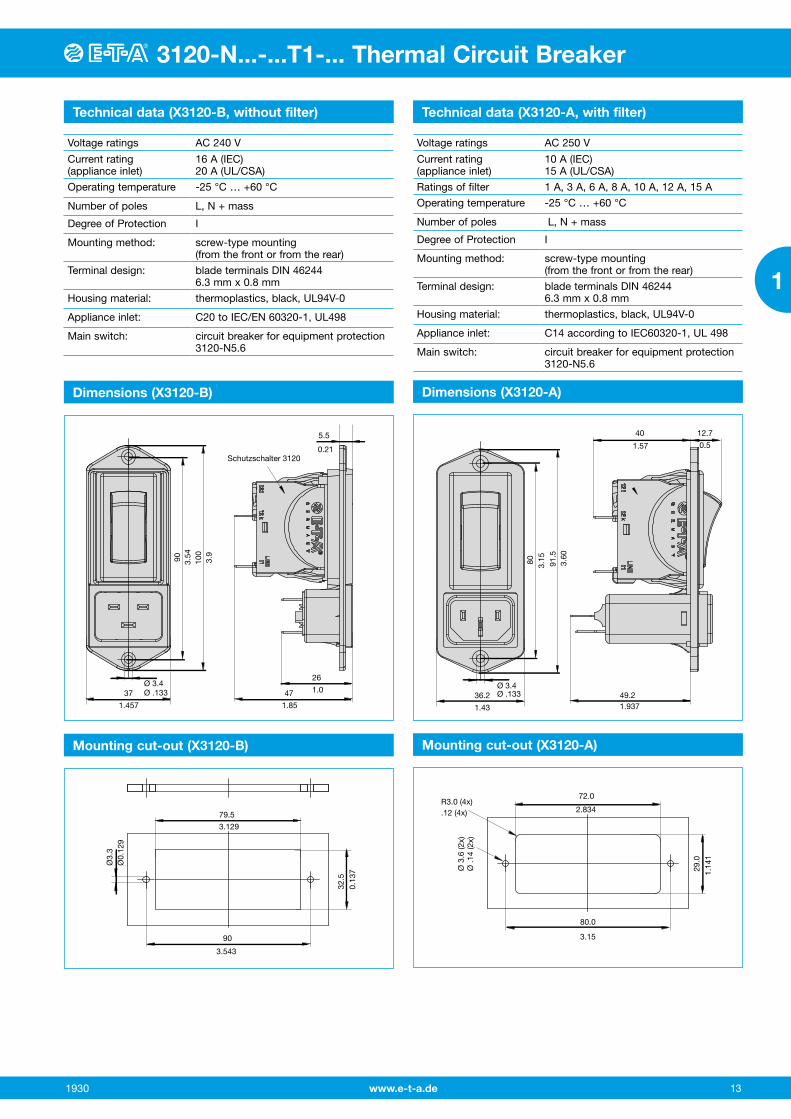
Technical data (X3120-B, without filter) Technical data (X3120-A, with filter)
Voltage ratings AC 240 V
Current rating (appliance inlet)
16 A (IEC)20 A (UL/CSA)
Operating temperature -25 °C … +60 °C
Number of poles L, N + mass
Degree of Protection I
Mounting method: screw-type mounting (from the front or from the rear)
Terminal design: blade terminals DIN 46244 6.3 mm x 0.8 mm
Housing material: thermoplastics, black, UL94V-0
Appliance inlet: C20 to IEC/EN 60320-1, UL498
Main switch: circuit breaker for equipment protection 3120-N5.6
Voltage ratings AC 250 V
Current rating (appliance inlet)
10 A (IEC) 15 A (UL/CSA)
Ratings of filter 1 A, 3 A, 6 A, 8 A, 10 A, 12 A, 15 A
Operating temperature -25 °C … +60 °C
Number of poles L, N + mass
Degree of Protection I
Mounting method: screw-type mounting (from the front or from the rear)
Terminal design: blade terminals DIN 46244 6.3 mm x 0.8 mm
Housing material: thermoplastics, black, UL94V-0
Appliance inlet: C14 according to IEC60320-1, UL 498
Main switch: circuit breaker for equipment protection 3120-N5.6
Mounting cut-out (X3120-B) Mounting cut-out (X3120-A)
Dimensions (X3120-B) Dimensions (X3120-A)
5.5
0.21Schutzschalter 3120
26
47 1.0
1.85
37
1.457
100
3.54
3.9
90
Ø 3.4Ø .133 36.2
1.43
80 3.15
91.5
3.60
Ø 3.4Ø .133 49.2
1.937
12.7
,0.5
40
1.57
90
3.543
79.5
3.129
32.5
0.13
7
Ø3.
3Ø
0.12
9
80.0
3.15
72.0
2.834R3.0 (4x).12 (4x)
Ø 3
.6 (2
x)
Ø .1
4 (2
x)
29.0
1.
141

www.e-t-a.de14
3120-N...-...T1-... Thermal Circuit Breaker
1930
1
Schematic diagram X3120-A
X3120-A0401 and X3120-A0403 – standard filters
X3120-A0406 – high-power filters
N
PE
P
N
PE
P
LineLoad
X3120-A0401General performance filter
X3120-A0403 und X3120-A0406High-performance filters for medical version
Cx N'
P'
PE
PE
11
21
LineLoadP'
11
21
12 (K)
22 (K)
12 (K)
22 (K)
2xL
Cx R N'2xL
2xCy
3120
3120
Typical filter attenuation: to CISPR 17 A = 50 Ω / 50 Ω sym; B = 50 Ω / 50 Ω asym; C = 0.1 Ω / 100 Ω sym; D = 100 Ω / 0.1 Ω sym
Typical filter attenuation: to CISPR 17 A = 50 Ω / 50 Ω sym; B = 50 Ω / 50 Ω asym; C = 0.1 Ω / 100 Ω sym; D = 100 Ω / 0.1 Ω sym
1 and 3 A models
1 and 3 A models
6 – 10 A models
6 – 10 A models
12 and 15 A models
12 and 15 A models

www.e-t-a.de 15
3120-N...-...T1-... Thermal Circuit Breaker
1930
1
3120-N...-...T1-... Thermal Circuit Breaker
Filter selection table
Filter Rating 50°C (25°C)
A
Leakage current 250VAC/50Hz
µA
Inductance L
mH
Capacity Cx
µF
Capacity Cy
nF
Resistance R
kΩ
X3120-A040101..M 1 (1.2) 373 12 0.1 2.2
X3120-A040103..M 3 (3.5) 373 2.5 0.1 2.2
X3120-A040106..M 6 (7.2) 373 0.78 0.1 2.2
X3120-A040108..M 8 (10.6) 373 0.5 0.1 2.2
X3120-A040110..M 10 (11.6) 373 0.225 0.1 2.2
X3120-A040112..M 12 (12) 373 0.11 0.1 2.2
X3120-A040115..M 15 (15) 373 0.075 0.1 2.2
X3120-A040301..M 1 (1.2) 2 12 0.1 1000
X3120-A040303..M 3 (3.5) 2 2.5 0.1 1000
X3120-A040306..M 6 (7.2) 2 0.78 0.1 1000
X3120-A040308..M 8 (10.6) 2 0.5 0.1 1000
X3120-A040310..M 10 (11.6) 2 0.225 0.1 1000
X3120-A040312..M 12 (12) 2 0.11 0.1 1000
X3120-A040315..M 15 (15) 2 0.075 0.1 1000
X3120-A040601..M 1 (1.2) 2 59.53 0.1 1000
X3120-A040603..M 3 (3.5) 2 13.45 0.1 1000
X3120-A040606..M 6 (7.2) 2 4.1 0.1 1000
X3120-A040608..M 8 (10.6) 2 2.3 0.1 1000
X3120-A040610..M 10 (11.6) 2 1.02 0.1 1000
X3120-A040612..M 12 (12) 2 0.58 0.1 1000
X3120-A040615..M 15 (15) 2 0.4 0.1 1000

www.e-t-a.de16
3120-N...-...T1-... Thermal Circuit Breaker
1930
1
Typical applications
Description X3120-U undervoltage release module
Order numbering code
Schematic diagrams
Technical data
Dimensions – undervoltage release module
1 blade terminal herausgeführtX3120-U01…
blade terminal2.8 x 0.8
flat head screw M3.5x6for mains connectiontightening torque max. 0.8 Nm
21
.82722.866
21
.827
6.6
.260
23,5.925
33.5
1.32 15°
7.6
.299
41 +0,1- 0,2
1.61 +.004- .008
Without separate terminal(s): X3120-U00…
Dimensional drawings of the standard version of 3120-N please see page 6-8
All machines that could cause personal injury upon automatic re-start, e.g. drilling machines, electric saws, meat cutting machines etc.
The X3120-U02 version allows set up of a cost-effective safety circuit via the physically isolated undervoltage release module, which enables implementation for example of a remote disconnection with emergency stop.
12(k)12(k) 12(k)
X3120-U00… X3120-U01… X3120-U02…
line
12(i) 22(i)
22(k)
U<
11 21
load
line
12(i) 22(i)
22(k)
U<
11 21
load
line line
12(i) 22(i)
22(k)
U<
11 21
load
lineA2 A1 A2
Type No.X3120 module for type 3120-N Module U undervoltage release module Design 00 standard (without separate connections) 01 1 blade terminal 2.8x0.8 02 2 blade terminals 2.8x0.8 Voltage ratings 00 AC 230/240 V 50/60 Hz 01 AC 120 V 50/60 Hz 02 AC 100 V 50/60 Hz 03 DC 24 V 04 AC 400 V 50/60 Hz Supply status M module mounted to circuit breaker 3120-N
X3120- U 00 00 M ordering example
All information and data given on our products are accurate and reliable to the best of our knowledge, but E-T-A does not accept any responsibility for the use in applications which are not in accordance with the present specification. E-T-A reserves the right to change specifi-cations at any time in the interest of improved design, performance and cost effectiveness, Dimensions are subject to change without notice. Please enquire for the latest dimensional drawing with tolerances if required. All dimensions, data, pictures and descriptions are for information only and are not binding. Amendments, errors and omissions excepted. Ordering codes of the products may differ from their marking.
Voltage ratings: AC 100 V; AC 120 V; AC 230/240 V; AC 400 V (50/60 Hz) DC 24 V
Voltage tolerances + 10 %/- 15 %
Typical life 20,000 cycles
Current consumption approx. 2.5 mA
Release values 0.2 x UN < U < 0.7 x UN(at a rated voltage of AC 100 Vthe device can trip at 70 V and must trip at 20 V)
Trip time < 20 ms
Reset value ≥ 85 % UN
Ambient temperature -30 … 60 °C
Vibration 8 g (57-500 Hz), ± 0.61 mm (10-57 Hz)test to IEC 60068-2-6, test Fc 10 frequency cycles/axis
Shock 30 g (11 ms)test to IEC 60068-2-27, test Ea
Corrosion 48 hours at 5 % salt mist, test to IEC 60068-2-11, test Ka
Humidity 240 hrs in 95 % RH test to IEC 60068-2-78,
test Cab
Mass approx. 56 g (including base unit)
The undervoltage release module reliably excludes personal injury through automatic re-start after voltage dip or power failure.
Note: Basic unit 3120-N...-H7 or -G7 requires screw terminals. Not possible in combination with PT terminals.
Please observe the following in combination with design version 4: In the event of voltage dip or power failure, the undervoltage release module trips the circuit breaker.
The rocker actuator will go into centre position. Reset is effectedin two steps:Step 1: Switch rocker into OFF position.Step 2: Reset circuit breaker.

www.e-t-a.de 17
3120-N...-...T1-... Thermal Circuit Breaker
1930
1
3120-N...-...T1-... Thermal Circuit Breaker
Add-on module for circuit breaker type 3120-N. The auxiliary contact module has a change-over contact as signal contact and is operated with actuation of the CBE.
Note: Not possible in combination with PT terminals.
Description X3120-S auxiliary contact module
Typical applications
Order numbering code
Schematic diagram
Technical data
Dimensions – auxiliary contact module
25.5
10
1421
blade terminals 2.8x0.5plated
19.8
7.5 7.5
2
8.5
.827
1.00
.394
.551
.335
.079
.295 .295
.780
Dimensional drawings of the standard version of 3120-N please see page 6-8
Status monitoring of CBE and/or the connected loads.
line11 21 34 32
12(i) 22(i) 31
12(k) 22(k)load
module mounted
Type No.X3120 module for type 3120-N Module S auxiliary contact module Design 0 change-over contact Terminal design 1 blade terminals DIN 46244-A6.3-0.8 Key for rated power A AC 10 V – AC 250 V 0.1 ... 4 A DC 12 V 0.1 ... 4 A DC 24 V 0.1 ... 4 A DC 60 V 0.1 ... 1 A DC 110 V 0.1 ... 0.5 A DC 220 V 0.1 ... 0.25 A B AC 5 V – AC 250 V 5 ... 100 mA DC 5 V – DC 250 V 5 ... 100 mA Supply status M module mounted to circuit breaker 3120-N
X3120- S 0 1 A M ordering example
All information and data given on our products are accurate and reliable to the best of our knowledge, but E-T-A does not accept any responsibility for the use in applications which are not in accordance with the present specification. E-T-A reserves the right to change specifi-cations at any time in the interest of improved design, performance and cost effectiveness, Dimensions are subject to change without notice. Please enquire for the latest dimensional drawing with tolerances if required. All dimensions, data, pictures and descriptions are for information only and are not binding. Amendments, errors and omissions excepted. Ordering codes of the products may differ from their marking.
Voltage ratings AC 250 V, DC 250 V
Current ratings 0.1...4 A / 5...100 mA
Typical life 50,000 cycles
Ambient temperature -30 … 60 °C
Dielectric strength
Between main andauxiliary circuit
test voltage AC 3,000 V
Insulation resistance > 100 MOhm (DC 500 V)
Vibration 6 g(57-500 Hz), ± 0.46 mm (10-57 Hz)test to IEC 60068-2-6, test Fc 10 frequency cycles/axis
Shock 15 g (11 ms) test to IEC 60068-2-27, test Ea
Corrosion 96 hours at 5 % salt mist, test to IEC 60068-2-11, test Ka
Humidity 240 hrs in 95 % RH test to IEC 60068-2-78, test Cab
Mass approx. 41 g (including base unit)

www.e-t-a.de18
3120-N...-...T1-... Thermal Circuit Breaker
1930
1
A module which adds remote trip capability to all versions of type 3120-N. A voltage applied across the coil will cause trip of the main switch/circuit breaker mechanism.
Note: Not possible in combination with PT terminals.
Description X3120-M remote trip module
Typical applications
Order numbering code
Schematic diagram
Technical data
Dimensions – remote trip module
blade terminals6.3 x 0.8 21
18
14
309
10.7
.827
1.18
.709
.551
.354
.421
Dimensional drawings of the standard version of 3120-N please see page 6-8
Electrical remote trip of safety systems.
12(k)
line
12(i) 22(i)
22(k)
11 21
load
FA
12
remote trip12(n)
modulemounted
Standard voltage ratings and typical internal resistance values
Type No.X3120 module for type 3120-N Module M magnetic trip module Design 2 magnetic remote trip coil Terminal design P7 blade terminals DIN 46244-A6.3-0.8 Supply status M module mounted to circuit breaker 3120-N Voltage ratings AC 120, 230 V DC 12, 24 V
X3120- M 2 P7 M -12 V ordering example
All information and data given on our products are accurate and reliable to the best of our knowledge, but E-T-A does not accept any responsibility for the use in applications which are not in accordance with the present specification. E-T-A reserves the right to change specifi-cations at any time in the interest of improved design, performance and cost effectiveness, Dimensions are subject to change without notice. Please enquire for the latest dimensional drawing with tolerances if required. All dimensions, data, pictures and descriptions are for information only and are not binding. Amendments, errors and omissions excepted. Ordering codes of the products may differ from their marking.
Voltage ratings
Internal internal resistance (Ω)
Voltage ratings
internal internal resistance (Ω)
DC 12 V 0.78 AC 120 V 71.0
DC 24 V 3.3 AC 230 V 312
Voltage ratings: AC 120...230 V; DC 12...24 V
Power consumption approx. 200 Watt
Pulse operation 20 ms < tON < 100 ms tOFF > 10 sec
Trip time < 20 ms
Typical life 50,000 operations at UN
ambient temperature -30 … 60 °C
Dielectric strength
Between mainand trip current circuit
test voltage AC 3,000 V
Insulation resistance > 100 MOhm (DC 500 V)
Vibration 8 g (57-500 Hz), ± 0.61 mm (10-57 Hz)test to IEC 60068-2-6, test Fc 10 frequency cycles/axis
Shock 30 g (11 ms)test to IEC 60068-2-27, test Ea
Corrosion 96 hours at 5 % salt mist, test to IEC 60068-2-11, test Ka
Humidity 240 hrs in 95 % RH test to IEC 60068-2-78, test Cab
Mass approx. 56 g (including base unit)

www.e-t-a.de 19
Thermal-magnetic circuit breaker 3120-N...-...M1-...
1930
1
3120-N...-...T1-... Thermal Circuit Breaker
Description
Typical applications
The 3120-N...-...M1-... thermal-magnetic circuit breaker/switch combination unites overcurrent protection and the function of an ON/OFF switch within a single component. The integral thermobimetal ensures ideally matched overload protection. The magnetic trip mod-ule trips the circuit breaker/switch combination at overload currents from four times rated current within milliseconds.
The 3120-N...-...M1-... meets the fire resistance requirements to EN 60335-1: 2007-02 Household and similar electrical appliances – Safety.
Electric motors, household appliances and office machines, electrical tools, power supplies, charging rectifiers
Current ratings and internal resistance values
Current rating (A)
Internal resistance per pole (Ω)
thermal-magnetic thermal 1.15 -1.38 x IN0.1 165 94
0.2 42.5 24
0.3 20.2 12
0.4 9.7 5.40
0.5 7.17 4.30
0.6 4.9 3
0.8 2.65 1.50
1 1.49 0.9
1.2 1.25 0.7
1.5 0.74 0.45
2 0.49 0.29
2.5 0.20 0.0785
3 0.14 0.0595
3.5 0.114 0.0565
4 0.092 0.0435
5 0.06 0.0325
6 0.043 0.0215
7 0.030 0.0215
8 0.029 0.02
10 0.021 0.02
12 < 0.02 < 0.02
14 < 0.02 < 0.02
15 < 0.02 < 0.02
16 < 0.02 < 0.02
Dimensions – magnetic trip module
blade terminals6.3 x 0.8 21
0.826
flat head screw M3.5x6 for mains connection tightening torque max. 0.8 Nm
Dimensional drawings of the standard version of 3120-N please see page 6-8
10
18
14
309
0.39
3
1.18
10.
354
41
3.5
15.5
0.708
0.5511.614
0.137
0.610
2111
I >
line
12(i) 22(i)
12(k) 22(k)
12
2111
I >
line
12(i)22(i)
12(k)
12
11
I >
line
12(i)22(i)
12(k)
12
therm.-magn. protection on one pole
therm.-magn. protection on one polethermally protected on the other pole
therm.-magn. protection on one poleunprotected on the other pole
Schematic diagrams
3120-N...-... M1-...

www.e-t-a.de20
Thermal-magnetic circuit breaker 3120-N...-...M1-...
1930
1
Approvals
Approval authority
Standard Voltage ratings Current rating range
VDE IEC/EN 60934
AC 240 V DC 50 V
0.1 ... 16 A0.1 ... 16 A
UL UL 1077 AC 250 VAC 125 V
0.1 ... 10 A0.1 ... 16 A
CSA C22.2 No 235
AC 250 V DC 125 V
0.1...10 A 0.1...14 A
CQC (CCC) GB 17701 AC 240 V DC 50 V
0.1...16 A 0.1...16 A
For further details please see: www.e-t-a.de/ti_eRated voltage AC 240 V, DC 50 V (AC 415 V upon request)
Current rating range 0.1…16 A
Typical life 1-pole
AC 240 V: 0.1...16 A 30,000 operations at 1 x IN, inductiveDC 50 V: 0.1...4 A 30,000 operations at 1 x IN, inductive 4.5...16 A 30,000 operations at 1 x IN, resistiveDC 28 V: 0.1...16 A 30,000 operations at 1 x IN, inductive
Typical life 2-pole
AC 240 V: 0.1...16 A 50,000 operations at 1 x IN, inductiveDC 50 V: 0.1...16 A 50,000 operations at 1 x IN, inductive
Ambient temperature -30... 60 °C
Insulation coordination(IEC 60664) 2.5 kV / 2 reinforced insulation in the operating area
Dielectric strength Operating area test voltage AC 3000 V Current path/current path test voltage AC 1500 V
Insulation resistance > 100 MOhm (DC 500 V)
Rupture capacity Icn (IEC/EN 60934)
IN UN Icn
1-pole, 2-pole 0.1 ... 2 A AC 240 V / DC 28 V
100 x IN
1-pole 0.1 ... 10 A DC 50 V 50 A
1-pole 2.5 ... 16 A AC 240 V / DC 28 V
200 A
2-pole 0.1 ... 2 A DC 50 V 10 x IN
2-pole 2.5 ... 16 A DC 50 V 250 A
2-pole 2.5 ... 16 A AC 240 V / DC 28 V
300 A
Interrupting capacity Inc (UL 1077)
IN UN Inc
1-pole, 2-pole 0.1 ... 10 A AC 250 V 2,000 A, C, 1
1-pole, 2-pole 0.1 ... 16 A AC 125 V 1,000 A, C, 1
Degree of protection (IEC 60529)Operating area
Terminal area
IP40 with water splash protection IP65
IP00 with water splash protection IP64
Vibration 8 g (57-500 Hz) ± 0.61 mm (10-57 Hz) test to IEC 60068-2-6, test Fc 10 frequency cycles/axis
Shock resistance 30 g (11 ms) test to IEC 60068-2-27, test Ea
Corrosion 96 hrs in 5 % salt mist test to IEC 60068-2-11, test Ka
Humidity 240 hrs in 95 % RH test to IEC 60068-2-78, test Cab
Mass approx. 53 g (2-pole) approx. 50 g (1-pole)
Technical data
Time/current characteristics
The time/current characteristic depends on the ambient temperature. In order to eliminate nuisance tripping, please multiply the current rating by a derating factor.
ambient tempera-ture [°C]
-30 -20 -10 0 23 40 50 60
temperature factor 0.8 0.84 0.88 0.92 1 1.08 1.14 1.23
… times rated current
Trip
tim
e in
sec
ond
s
… times rated current
0.1…2 A
2.5…16 A AC/DC 1)
Single or double pole load
1 2 4 6 8 10 20 40
10000
1000
100
10
1
0.1
0.01
0.00160 80 100
1 2 4 6 8 10 20 40
10000
1000
100
10
1
0.1
0.01
0.00160 80 100
Trip
tim
e in
sec
ond
s
1) Magnetic tripping currents are increased by 25% on DC supplies.
AC/DC 1)

www.e-t-a.de 21
Thermal-magnetic circuit breaker 3120-N...-...M1-...
1930
1
Thermal-magnetic circuit breaker 3120-N...-...M1-...
Order numbering code
Type No.3120 thermal-magnetic circuit breaker/switch combination with
rocker actuation Mounting method N3 snap-in, mounting cut-out 50.5 x 21.5 mm N5 snap-in, mounting cut-out 44.5 x 22 mm Number of poles 1 1-pole switching, 1-pole thermal-magnetically protected 2 2-pole switching, 2-pole protected (pole one: thermal-
magnetically protected, pole Two: thermally protected 5 2-pole switching, 1-pole thermal-magnetically protected Style 1 standard 3 with actuator guard 4 with water splash protection (IP65) 6 version for appliance inlet modules
X3120-A/-B (only for mounting method N5) with actuator guard and cross-hole Terminal design P7 blade terminals H7 as P7, terminals 11 and 21 with additional flat
head screws M3.5 N7 as P7, with additional shunt terminals 12(i)
and 22(i) G7 as N7, terminals 11 and 21 with additional flat
head screws M3.5 Trip curve M1 medium delay, thermal- 1.01-1.4 x IN;
magnetic 4-9 x IN AC Actuator W rocker Rocker colour and illumination 01 . black without illumination 02 . white without illumination 04 . red without illumination 12 . Y white with illumination 14 . R red with illumination 15 . Y orange with illumination 16 . T blue with illumination 19 . G green with illumination Marking of rocker actuator rocker style A (not for style 4) D F K L X Illumination voltage range (= operating voltage) 1 DC 12 V 2 DC 24 V 3 AC 115 V 4 AC 230 V 5 DC 48 V 6 AC 400 V (for 2-pole versions) Current ratings 0.1 ... 16 A
3120-N5 2 4 - M1-W 19 D G 4 - 16 A ordering example
A D F K L X
Order numbering code
Type No.3120 thermal-magnetic circuit breaker/switch combination with
push button actuation Mounting method N3 snap-in, mounting cut-out 50.5 x 21.5 mm N5 snap-in, mounting cut-out 44.5 x 22 mm Number of poles 1 1-pole switching, 1-pole thermal-magnetically protected 2 2-pole switching, 2-pole protected (pole one: thermal-
magnetically protected, pole two: thermally protected 5 2-pole switching, 1-pole thermal-magnetically protected Style D with actuator guard E with actuator guard and water splash cover F with power-on protection V with power-on protection and water splash cover Terminal design P7 blade terminals H7 as P7, terminals 11 and 21 with additional flat
head screws M3.5 N7 as P7, with additional shunt terminals 12(i) and 22(i) G7 as N7, terminals 11 and 21 with additional flat
head screws M3.5 Trip curve M1 medium delay, thermal- 1.01-1.4 x IN;
magnetic 4-9 x IN AC Actuator S two push buttons Colour of push button/illumination
(style D and F without water splash protection)
GRD green/red without illumination GRDXG green with LED illumination/red
without illumination Colour of push button/illumination
(style E and V with water splash pro-tection)
GRX green/red without illumination GRXG green with LED illumination/red
without illumination Illumination voltage range (= operating voltage) 1 DC 12 V 2 DC 24 V 3 AC 115 V 4 AC 230 V 5 DC 48 V 6 AC 400 V (for 2-pole versions) Current ratings 0.1 ... 16 A
3120-N3 5 V - P7 M1-S GRXG - 16 A ordering example
Please observe our minimum ordering quantities.

www.e-t-a.de22
Thermal-magnetic circuit breaker 3120-N...-...M1-...
1930
1Order numbering code
Type No.3120 thermal magnetic resettable circuit breaker with push button Mounting method N3 snap-in, mounting cut-out 50.5 x 21.5 mm N5 snap-in, mounting cut-out 44.5 x 22 mm Number of poles 1 1-pole switching, 1-pole thermal-magnetically protected 2 2-pole switching, 2-pole protected (pole one: thermal-
magnetically protected, pole two: thermally protected 5 2-pole switching, 1-pole thermal-magnetically protected Style G resettable circuit breaker Terminal design P7 blade terminals H7 as P7, terminals 11 and 21 with additional flat
head screws M3.5 N7 as P7, with additional shunt terminals 12(i)
and 22(i) G7 as N7, terminals 11 and 21 with additional flat
head screws M3.5 Trip curve M1 medium delay, thermal- 1.01-1.4 x IN;
magnetic 4-9 x IN AC Actuator D one push button Colour of push button 01 black Marking of push button X without marking Current ratings 0.1 ... 16 A
3120-N3 2 G - P7 M1 - D 01 - X 16 A ordering example
Please observe our minimum ordering quantities.
Customer-specific solutions
Looking for a version you cannot find in our ordering number code? Please get in touch.