38911794j isp gb 0410 qxp5 entwurf - b.braun medical...
TRANSCRIPT

Infusomat® Spaceand Accessories
Instructions for Use
Valid for software 686MGB
It is recommended that all pumps atyour care unit are equipped with thesame software version.

CONTENTS
Infusomat® Space Overview ...................................................................................................3Symbols on Product...................................................................................................................5Patient Safety ........................................................................................................................6Menu Structure / Navigation ...............................................................................................11Chapter 1 Operation..........................................................................................................14 1.1 Start of Infusion .........................................................................................................................14 1.2 Entry With Different Combinations of Rate, VTBI (= Volume To Be Infused) and Time........................................................................................................................................16 1.3 Bolus Application .......................................................................................................................17 1.4 Infusion Line Change and New Therapy Start...................................................................18 1.5 End of Infusion............................................................................................................................20 1.6 Standby Mode .............................................................................................................................20
Chapter 2 Advanced Operations ....................................................................................21 2.1 Status Request of Pump when Infusion is Running ........................................................21 2.2 Rate, VTBI and Time Change Without Infusion Interruption and Reset of Status Menu Data.................................................................................................................21
Chapter 3 Special Functions*..........................................................................................22 3.1 Dosing Units and Dose Rate Calculation (Overview).......................................................22 3.2 Dose Rate Calculation (Operation)........................................................................................22 3.3 Drug Library..................................................................................................................................23 3.4 Patient Controlled Analgesia (PCA) (optional) ..................................................................26 3.5 Target Controlled Infusion (TCI) (optional) .........................................................................27 3.6 Barcoding......................................................................................................................................33 3.7 Piggyback Function....................................................................................................................34 3.8 Ramp and Taper Mode..............................................................................................................36 3.9 Program Mode.............................................................................................................................39 3.10 Intermittent Mode.....................................................................................................................40 3.11 Dose Over Time ...........................................................................................................................43
Chapter 4 Autoprogramming..........................................................................................45Chapter 5 Options ..............................................................................................................49 5.1 Occlusion Pressure .....................................................................................................................49 5.2 Upstream Occlusion Pressure .................................................................................................49 5.3 Data Lock ......................................................................................................................................49 5.4 Bolus Rate.....................................................................................................................................50 5.5 KVO-Mode ....................................................................................................................................51 5.6 Contrast / Display Light / Keypad Light...............................................................................51 5.7 Alarm Volume ..............................................................................................................................51 5.8 Date / Time ...................................................................................................................................51 5.9 Macro Mode.................................................................................................................................51 5.10 Language.......................................................................................................................................52
Chapter 6 Alarms................................................................................................................53 6.1 Device Alarms..............................................................................................................................53 6.2 Pre-Alarms and Operating Alarms ........................................................................................53 6.3 Reminder Alarms ........................................................................................................................56 6.4 Alarm Hints ..................................................................................................................................56
Chapter 7 Battery Operation and Maintenance .......................................................57Chapter 8 Start Up Graphs and Trumpet Curves ......................................................59Chapter 9 Technical Data.................................................................................................60Chapter 10 Warranty / Training / TSC** / Service / Disinfecting / Disposal ......67Chapter 11 Instructions for Use Accessory ...................................................................71Ordering ......................................................................................................................76
*The availability ofthe listed featuresis depending onthe configurationof the pump.**Technical SafetyCheck.
2
Port for drop sensor
INFUSOMAT SPACE® OVERVIEW
INFUSOMAT® SPACE OVERVIEW
3
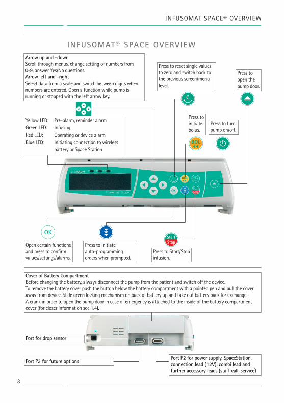
Arrow up and -downScroll through menus, change setting of numbers from0-9, answer Yes/No questions.Arrow left and -rightSelect data from a scale and switch between digits whennumbers are entered. Open a function while pump isrunning or stopped with the left arrow key.
Press to reset single valuesto zero and switch back tothe previous screen/menulevel.
Press to Start/Stopinfusion.
Press to initiateauto-programmingorders when prompted.
Open certain functionsand press to confirmvalues/settings/alarms.
qc
k m
Port P3 for future options
Cover of Battery CompartmentBefore changing the battery, always disconnect the pump from the patient and switch off the device.To remove the battery cover push the button below the battery compartment with a pointed pen and pull the coveraway from device. Slide green locking mechanism on back of battery up and take out battery pack for exchange.A crank in order to open the pump door in case of emergency is attached to the inside of the battery compartmentcover (for closer information see 1.4).
Press toinitiatebolus.
Press to turnpump on/off.
Port P2 for power supply, SpaceStation,connection lead (12V), combi lead andfurther accessory leads (staff call, service)
Yellow LED: Pre-alarm, reminder alarmGreen LED: InfusingRed LED: Operating or device alarmBlue LED: Initiating connection to wireless battery or Space Station
Press toopen thepump door.
x
onB
Sf

INFUSOMAT® SPACE OVERVIEW
4
TransportA maximum of three pumps (Infusomat®Space or Perfusor® Space) plus oneSpaceControl may be stacked together (inambulance cars and helicopters only onepump). Avoid external mechanicalinfluence.Locking Devices TogetherLine up the bar of the lower pump with thebar of the pump above and slide the lowerpump backwards until the lock clicks andthe green buttons are above each other.To disconnect, push green locking buttonsof top pump device and slide bottom pumpforward.Caution: Avoid external mechanicalaction.
Pole FixationPush the opening of the PoleClamp againstthe vertical pole and lock the screw tightly.Unscrew to release.For vertical fixation of PoleClamp pushlever down and rotate either way until leverclicks into notch. Push lever for rotation.Caution: Do not lean on pump whenattached to pole!Caution: A maximum of three B. BraunSpace pumps can be stacked togetherwhen used with the PoleClamp SP.
Opening lever
Pump based free flowprevention safety clamp
Yellowcaution light
Downstreampressure sensor
Upstreampressure sensor
Line guidecover
Airsensor
Fixaton of PoleClamp (Universal Clamp)Line up bar of pump with bar of PoleClampand slide PoleClamp forward until lockingmechanism clicks. To remove, press release button on frame,push handle down and pull PoleClamp backwards.
Pole clamp handle
Pole clamp release button
Pump slots

5
SYMBOLS ON PRODUCT
SYMBOLS ON PRODUCT
Symbol Explanation
See accompanying documents.
Type CF unit with defibrillation protection
Protection class II device
Symbol indicating separate collection for electrical and electronic equipment (2002/96/EC)
CE mark compliant to Directive 93/42/EEC
Temperature Limit
Moisture Limit
Limitation of the atmospheric pressure
Mandatory action: see instruction for use.
Non-ionizing electromagnetic radiation
General warning sign (e.g. Caution)

6
PATIENT SAFETY
PATIENT SAFETY
Read Instructionsfor Use prior to use.The infusion deviceshould only beused by speciallytrained staff.
Intended use
The Infusomat® Space Volumetric Infusion Pump System includes an externaltransportable electronic volumetric infusion pump, dedicated administrationsets, and pump accessories. The system is intended for use on adults, pediatrics,and neonates for the intermittent or continuous delivery of parenteral andenteral fluids through clinically accepted routes of administration. These routesinclude, but are not limited to intravenous, irrigation/ablation, and enteral. Thesystem is used for the delivery of medications indicated for infusion therapyincluding but not limited to colloids and cristalloids, blood and blood components, Total Parenteral Nutrition (TPN), lipids, and enteral fluids. TheInfusomat® Space Volumetric Infusion Pump System is intended to be used bytrained healthcare professionals in healthcare facilities, home care, outpatient,and medical transport environments.
Using TCI the scope of patients is:
Some parameter sets are using the Lean Body Mass (LBM) to individualize theparameterization. The LBM calculation may furthermore restrict the scope ofpatients as it will not allow TCI for obese patients.
Using TCI the scope of procedures is:
• Propofol: Anaesthesia and Conscious Sedation• Remifentanil: Anaesthesia
Qualified medical staff should decide how the device should be used based onits features and specifications. For more details, please read the Instructions forUse.
Operation
• The initial training of the Infusomat® Space is to be performed by B. Braun sales personnel or other authorized persons. After each software update, the user is required to inform himself about the changes to the device and accessories in the instructions for use.
4w Caution: Ensure the unit is properly positioned and secured. Do not position pump unit above patient or in a position where a patient could come to harm, should the pump fall.
• Prior to administration, visibly inspect the pump for damage, missing parts or contamination and check audible and visible alarms during selftest.
• Not be used adjacent and stacked with other equipment except B. Braun Space devices.
w
Height [cm]Weight [kg]
Age [Yrs]
30Minimum Maximum
200130 22016 100

7
PATIENT SAFETY
• Only connect to patient once the line has been correctly inserted and completley primed. Interrupt connection during line change to prevent incorrect dose delivery.
• Select infusion line/catheter suitable for use with the intended medical application.
4w Caution: Position the infusion line free of kinks.
• Recommended change of disposable every 96 h (or as per national hygiene regulations).
• Installation in medically used rooms must comply with the appropriate regulations (e.g. VDE 0100, VDE 0107 or IEC-publications). Observe national specifications and deviations.
4w Caution: Operate the pump at least 25 cm from flammable anaesthetics toprevent explosion.
• Compare the displayed value with the entered value prior to starting infusion.
• If staff call is used we recommend checking the equipment once after connecting the pump.
• Protect the device and the power supply against moisture.
• If the pump falls down or is exposed to force, it must be checked by the service department.
• The displayed data must always be checked by the user prior to making further medical decisions.
• During mobile use (homecare, patient transport inside and outside the hospital): Make sure the device is securely fixed and positioned. Positioning changes and severe shock can lead to minor changes in the delivery accuracy and/or unintentional bolus administration.
• A supplemental patient monitoring must be carried out if life-saving medication is performed.
• The air detector cannot detect air diffusing in the following components: three-way stopcocks, infusion adapters and further lines placed between pump and patient.
• In case high potent drugs are given be sure to have a second infusion pump for that drug at hand. The therapy documentation should be suitable to continue the therapy at the second infusion pump.
• Independant of the soft limits the selected values have to be the medically correct ones for the given patient.
• In case values relevant for the dose rate calculation are changing always the flow rate will be updated and the dose rate will be fix.
• Consider startup characteristics before using low infusion rates (0.1ml/h) with critical drugs.

8
PATIENT SAFETY
Enteral NutritionThe Infusomat® Space may be used for enteral nutrition. Do not use enteral flu-ids for intravenous infusion as this may harm your patient. For this reason onlyuse disposables dedicated and labeled for enteral nutrition.
Transfusion
The Infusomat® Space may be used for blood transfusion, too. For this therapyonly use disposables dedicated and labelled for transfusion.
Other components• Use only pressure-proof and compatible disposable items (min. 2 bar/ 1500 mm Hg) to avoid influencing performance data - which would result in impairing patient safety.
• Where several infusion lines are connected on one single vascular access, the possibility of the lines exerting a mutual influence over each other cannot be excluded.
• Refer to respective manufacturer’s information for possible incompatibilities of equipment with respect to drugs.
• Use only compatible combinations of equipment, accessories, working parts and disposables with luer lock connectors.
• Connected electrical equipment must comply with the relevant IEC/EN- specifications (e.g. IEC/EN 60950 for data-processing equipment). The user/operator is responsible for the system configuration if additional equipment is connected. The international standard IEC/EN 60601-1-1 has to be taken into account.
Safety Standards
Infusomat® Space satisfies all safety standards for medical electrical devices incompliance with IEC/EN 60601-1 and IEC/EN 60601-2-24.
• The EMC-limits (electro-magnetic compatibility) according to IEC 60601-1-2:2007 and IEC 60601-2-24: 2012 are maintained. If the equipment is operated in the vicinity of other equipment which may cause high levels of interference (e.g. HF surgical equipment, nuclear spin tomography units, mobile telephones etc.) may be disturbed. Maintain the protective distances recommended by the manufacturers of these devices.
• The Infusomat® Space fulfils the applicable requirements of EN 13718 to be used in the air, on the water and in difficult terrain. During transport the Infusomat® Space needs to be fixed on a suitable restraint system by means of SpaceStation or Pole Clamp SP. When stored under temperature conditions beyond the defined operating conditions the Infusomat® Space needs to remain under room temperature at least one hour before usage.
9
• As there is no dedicated norm existing for enteral feeding pumps the safety features of Infusomat Space are also for enteral nutrition according to the a.m. norms.
Safety instructions for using PCA
• In case the demand button is used with SpaceStation the PCA pump has to be placed in the lowest slot of the lowest SpaceStation.
• Access to the pump settings can be prohibited by DataLock 3. The code for DataLock level 3 should differ from the one for levels 1 and 2 in case the pump is only allowed to be used by pain management professionals.
• When ending PCA and starting it again the therapy data are set to default values.
• Using the demand button also the patient is a permitted user. With the demand button only a PCA-bolus can be requested. This is limited to pre- defined doses by drug list and pump settings.
Safety instructions for using TCI
• TCI should only be performed by experienced anaesthetists being familiar with the principles of TCI and properly trained in using the present device.
• The use of TCI with B. Braun Space does not limit the responsibility of the anaesthetist for administration of drugs. They need to be fully aware of the available literature for any parameter set used in association with a drug and need to refer to the prescribed information for rate and dosing limits.
• Pharmacokinetic and pharmacodynamic interactions among anaesthetic drugs are known, but are not taken into account into the calculation of the plasma and effect site concentrations. They have to be taken into account by the user.
• In particular, the user must be aware that starting the TCI will result in the automatic infusion of a pre-calculated bolus dose followed by an infusion to achieve the selected target concentration.
• It is essential that the user verifies that the patient characteristics and the selected target concentration as well as the resulting dosages conform to the prescribing information of the relevant country.
• B. Braun has verified the accuracy of the mathematical model implementation, the usability as well as pump delivery accuracy.
• While using TCI an appropriate patient monitoring is mandatory.
• Take care of using the right dilution/concentration of the drug and make sure the right dilution is selected at the pump.
• Never administer Propofol or Remifentanil by a second infusion as long as you use TCI.
PATIENT SAFETY

10
PATIENT SAFETY
• It is possible to completely switch off the TCI mode to avoid the use of TCI accidentally.
• By using Infusomat® Space a change of drug concentration will not be possible within the same therapy.
Safety Instructions for using Pole Clamp
1. Line pump up with the Pole Clamp guide rails.
2. Slide pump fully into place onto the guide rails.
3. An audible “Click” should heard.
4. Test the pump is secure.
WThe pump ist now securely attached toPole Clamp.
• Do not lean on the pump when attached to the Pole Clamp.
• Do not position the pump unit above the patient.
W• DO NOT use any Pole Clamp that shows signs of damage.
• DO NOT use Pole Clamp with missing clamp grids.
Underside viewClamp grids

11
At the top of the screen the last therapy isindicated. Yes/No question can beanswered by pressing u for yes or dfor no.
Parameters which can be changed (e.g.rate in ml/h) are opened with l ork. When editing parameters, switchdigits/levels using l r. Whitebackground indicates current digit/level. Use u or d to change currentsetting. Help text on the bottom/top ofthe screen indicates options how toproceed (e.g. confirm rate with k,start infusion with sf or clear rate bypressing c).
Display Meaning
Mainsconnection
Batterystatus
Unit of drug application
Active VTBI- or time preselection
Scrolling arrows indicate pump is infusingSet rate can be opened with l
Set pressure limit andcurrent pressure
Therapy profile
Typical display during infusion:
Total volume infused. Alternatively the intermediate volume can be displayed.Remaining time Remaining VTBI
Cutline
MENU STRUCTURE / NAVIGATION
MENU STRUCTURE / NAVIGATION
o On/Off button
x Door open button
sf Start/Stop button
nb Bolus button
C Clear button
K OK button
Q Keypad with arrow up, -down, -left, -right button
m Connection button
All display screen shots are examples and may be different when related to anindividual patient and individualized therapy.

12
MENU STRUCTURE / NAVIGATION
nb has been pressed while the pump isinfusing. Start manual bolus at1200 ml/h by pressing k (see top ofdisplay) or proceed to set bolus limitwith l (see bottom of display).
All status information is available in thebottom line of the display. The desiredinformation can be selected by using du and will be displayed permanentlythereafter (e. g. drug long name, currentsystem pressure etc.).
Display Meaning
Set pressure level with l or r and con-firm by pressing k.Cancel to edit pressure by using c.
Pre-alarms are indicated by a message onthe display (e.g. “VTBI near end”), anaudible tone and the yellow LED is constantly on. To confirm a pre-alarmpress k.
In case of an operating alarm (e.g. "VTBIinfused") the infusion stops, an audibletone sounds and the red LED flashes.Confirm alarm by using k. Confirming does not activate an acousticfeedback.
This hint pops up if a user tries to edit orchange a parameter by pressing l whenthat parameter is unable to be changed.
Press and hold o for 3 sec to turn pumpoff. A white bar stretches from left to rightand counts down the 3 sec.As long there is an infusion line insertedthe pump will not turn off but will usestandby.

13
MENU STRUCTURE / NAVIGATION
Prime ?
Start UpMenu
MainMenu
StatusMenu
Lineselection
Rate
SpecialFunctions
Dose RateCalculation
VTBI
Time
Use lasttherapy ?
Use druglibrary ?
Use dose ratecalculation ?
Weight
Concentration
Dose
Drug Library
Change-overfrom
continuousmode to PCA
Intermediatevolume
Intermediateamount
Intermediatetime
Totalvolume
SpecialFunctions
Options
Status
OptionsMenu
OcclusionPressure
Totalamount
Totaltime
Line
Batterycapacity
WLan
Version
Druginfo
BolusRate
KVO-Mode
DisplayLight
KeypadLight
AlarmVolume
Data Lock
Contrast
Date
Time
MacroMode
In Dose Mode:Display of flowrate in large
scale
Language

14
Chapter 1
OPERATION
OPERATION
1.1 Start of Infusion
• Ensure that the pump is properly installed. Check the equipment for completeness and damages. Do not attach the infusion bottle below the pump level.
• Put the spike vertically into the infusion bottle. Fill the bottom part of the drop chamber by max. 2/3.
4w Caution: Close the roller clamp before inserting the IV line and do notconnect to patient until properly loaded and primed.
• If the device is connected to the mains, the display indicates the battery status, the mains connection symbol and the last therapy.
• Press o to switch on the device. Observe the automatic self-test: The message “Self-test active” and the software version are displayed, two audible tones sound and all three LEDs (yellow, green/red and blue) flash once. Information about the power supply (mains or battery operation) and the set pressure level are indicated. In addition, the line type appears at first (provided that the line is already inserted). Then, the accumulated air volume and the max. size of air bubbles is indicated which is triggering the air alarm of the device.
• Press c to start the direct entry of therapy parameters, or press x and u to open the pump door in order to continue with inserting the line.
4w Caution: Close the roller clamp before inserting the IV line and do not connect to patient until properly loaded and primed.
Caution: You may only insert the line while the device is switched on and the lineguide element is inserted. Otherwise, there is the danger of freeflow. Pay attention tokeep the roller clamp closed before inserting the infusion line especially at a tempera-ture scale of 10 - 15 °C. Never leave the pump unattended when inserting the tube.
Caution: Inserting different lines into the pump is identical. Please see instructions andpackaging of the different lines (standard, transfusion, opaque, enterel nutrition etc.)to receive information about preparation and usage of these lines.
• Firmly press tubing into the air sensor guide to make sure the line is properly
The pump offers the possibility to load up to four languages into the pump (depending on the number of the language specific characters), among which theuser can choose during the operation of the pump. During the first ever start-up ofthe device, the user is requested to select the languages and to mark them with l.After that, the selection has to be confirmed by choosing the last menu item at thebottom of the list and pressing k. Then the desired language must be selected witht and confirmed with k. Answer the following question with d in order to activate the selected language.

15
OPERATION
Chapter 1
inserted into the sensors. Thread the tubing through the notches on the right and left side of the pump.
• Close the pump door by firmly placing pressure with both hands on each side of the pump door, continue to press firmly until you hear and feel the motorized door latch pull the door shut. Do not open roller clamp until the pump directs you to do so when self test is completed. Then select the inserted line with t and confirm it with l. Open the roller clamp.
Caution: Do not force door closed – If door is difficult to close, please check IV set andanti free-flow slide clamp (green) for proper installation.
Caution: Before opening door, please close roller clamp and ensure door does not fallopen. If door opens to the horizontal position, please check that the slide clamp (green)is properly occluding the IV set and the door extension hook is not broken. If the doorhook is found damaged or broken remove the pump from service.
Caution: If a wrong line is selected the time until the pump goes into a pressure alarm
Next attach the white clip.Insure silicone segment is notstretched or twisted, stars on tubingmust be in straight line and shouldnot be twisted.
Insert the freeflow clamp (see redarrow) in the opened aperture, in thedirection indicated by the arrow, untilthe opening lever locks in and thesafety clamp squeezes the lines(flashing signal lamp goes out).
Insert the infusion line from right tothe left. Make sure that the line isrouted straight. At first, route the linethrough the upstream sensor. Then,insert the two-hole clip.
16
may be prolonged. Also a wrong delivery rate is possible.
• Press u if the prime function is enabled to prime the infusion line with the rate displayed. Cancel priming with k. Repeat the procedure until the line is completely primed. Then press d to proceed.
Note: During priming, all air and drop alarms are switched off.
• Establish the patient connection.
• Answer the question whether the old therapy is to be used either with u or d (the question can be deactivated via the service manual). If you select u, the pump jumps to the Main Menu.
Note: At rates smaller 1 ml/h the detection of a closed roller clamp cannot always beensured due to physical reasons. A drop sensor may be used to avoid this risk.
Adjusting the delivey rate:
• In the Main Menu, open the rate with l and set it with q.
• Press sf to start the infusion. VTBI is required to start the infusion. Time will be calculated when rate is entered. When time is entered, rate/doserate will be calculated. Running arrows on the display and the green LED indicate that the pump is infusing.
Note: If Infusomat Space Line SafeSet is used, VTBI is not required.
Note: The running infusion can be cancelled at any time by pressing sf. Thepump can be turned off at any time by pressing o for 3 sec (Exception: Datalock level 2) and as long a disposable is inserted.
1.2 Entry With Different Combinations of Rate, VTBI (= Volume To Be Infused) and Time
The Infusomat® Space offers the possibility to enter a volume- and time limit inaddition to an infusion rate. When two of these parameters are entered, the third iscalculated by the pump. If a volume and/or time is preselected, an arrow symbol isplaced in front of one of these parameters in the Main Menu. It is called the “target”.During the infusion of the pump, this target symbol is displayed next to the moving arrows in the run display (this symbol is not visible in case TCI is used). This indicatesthat the pump has been programmed, either with a volume- or time limit. The assignment of the target symbol, apparent in the Main Menu, shows the establishedparameter for the application (VTBI or time). When the rate is changed, the so-calledtarget parameter is principally not adjusted to the new rate but to the parameterwhich does not have the target symbol in front. After the infusion has started, the remaining VTBI and time are displayed in the status menu and the run display (values are counting down).
Chapter 1
OPERATION

17
OPERATION
1.) Enter VTBI and time: The infusion rate will be calculated and displayed on the bottom of the display. Target: Volume
• Select VTBI with t and open withl.
• Enter VTBI with qand confirm with k.
• Select time with t and open withl.
• Enter time with q and confirm with k.
Check calculated rate on plausibility.
Proceed in the same way to calculate 2.) and 3.).
2.) Infusion with volume limit Enter rate and VTBI: The infusion time will be calculated and displayed on the bottom of the display. Target: VTBI
3.) Infusion with time limit Enter rate and time: The infusion volume will be calculated and displayed on the bottom of the display. Target: Time
Changing already entered values of VTBI and time (rate, VTBI and time already existat the point of change):
a) Target symbol is placed in front of VTBI: • Change of VTBI => Adjustment of time. Old and new target: VTBI • Change of time => Adjustment of rate. Old and new target: VTBI
b) Target symbol is placed in front of time: • Change of time => Adjustment of VTBI. Old and new target: Time • Change of VTBI => Adjustment of time. New target: VTBI
1.3 Bolus Application
After pressing the buttonnb, the bolus unit can be selected by using d.
Note: The selected unit will not be stored. It is possible to administer a bolus in ml.
There are three ways to administer a bolus:
1.)Manual Bolus: Press nb. Then press k and hold button. Fluid is administered for as long as the button is held down.. The infused bolus volume is displayed. The max. bolus time is limited to 10 sec. Reaching this limit is indicated by an acoustic signal.
2.)Bolus with volume preselection: Press nb. Then press l and set bolus dose limit by using q. Press nb to confirm and start bolus. Depending on the
Chapter 1

18
Chapter 1
OPERATION
service tool settings an acoustic signal will sound after finishing the bolus volume.
3.)Bolus with rate calculation: Press nb. Then press l and set bolus dose by using q. Press k to confirm bolus dose. Set time with q in which a bolus is to be delivered. Calculated bolus rate is shown on top of the display. Press nb to confirm and start bolus.
You can use the service program to enter a default and a maximum bolus rate.Once a new therapy is started the device always returns to the default rate- even if the bolus rate was manually changed beforehand.
Note: If the bolus limit is not entered after pressing nb, the pump switchesback into the run display automatically.
Note: The infused volume during bolus with volume preselection counts up.
In order to purge the line at any time while the pump is stopped press nb.
Answer the following question by pressing u in order to start the purge process. Cancel by pressing k or any other key.
Caution: Take care not to overdose! Given a bolus rate of 1200 ml/h, 1 ml willbe administered in just 3 sec. To cancel bolus infusion at any time press k. At low bolus volumes, under dosages due to the start up characteristic of thepump and the tolerances in the infusion system cannot be excluded. Disconnectpatient while purging.
1.4 Infusion Line Change and New Therapy Start
Note: Always interrupt the patient connection before changing a line to avoid dosingerrors. Never let the pump run unattended when changing the line. Check and cleanthe safety clamp regularly.
• Press sf to stop the delivery. The green LED goes out. Close the roller clamp and interrupt the patient connection.
• Press x and open the pump door with u. Press down the green opening lever completely until it locks in place, remove the line and insert a new line.
Note: In the unlikely event the pump door cannot be opened remove the allen key fromthe inside of the battery compartment cover. Use this key to remove the emergency aperture cover of the pump. Place the crank in the aperture and turn itclockwise until the pump door opens.

19
ADVANCED OPERATIONS
Push cover opening with pen.
Remove crank from inside of battery cover.
Turn crank to remove emergencyaperture cover.
Remove emergency aperture cover.
Turn crank inside aperture to open the door.
Chapter 2

20
Chapter 1
OPERATION
• Close the pump door, confirm the inserted line with k and open the roller clamp.
• If required, prime the pump with u. Then press d to proceed when priming is complete.
• Establish the patient connection and check the parameters with t.
• Start the infusion by pressing sf.
Note: A new therapy can be started at any time during a stopped infusion. If the pumpis in the Main, Status or Options Menu, press C (repeatedly) and follow theinstructions as described.
1.5 End of Infusion
• Press sf to stop the infusion. The green LED goes out. Close the roller clamp and interrupt the patient connection.
• Press x. Answer the question whether the pump door is to be opened with u.
• Press down the green opening lever completely until it locks in place. Remove the line and close the pump door.
• Press o for 3 sec to switch off the pump.
Note: The settings will be permanently saved by the switched off device.
Note: Pump cannot be powered off with IV line inserted.
1.6 Standby Mode
In the case of extended interruption, the user has the option to maintain the set values.
• Press sf to stop the infusion. Then press o for less than 3 sec.
• Confirm that the pump is supposed to switch to standby by pressing u.
• The pump is now in Standby.
While the pump is in the standby mode, it’s display shows the drug and the remainingtime for this mode, standby may be set from 1 min to 24 hours. Change of remainingtime by pressing l. Exit standby by pressing c . The pump will alarm when thestandby time expires.
As long as a disposable is inserted in the pump will use standby also in case o ispressed for at least or more than 3 sec.

21
ADVANCED OPERATIONS
ADVANCED OPERATIONS
2.1 Status Request of Pump when Infusion is Running
Press c to switch between run display and Main Menu while the device isinfusing. Navigate through the menu using t to check parameters. In order tocheck the menu parameters in the Status-/Options Menu, select "Status" respectively "Options" in the Main Menu, open menu with l and scrollthrough menu with t.
2.2 Rate, VTBI and Time Change Without Infusion Interruption and Reset Of Status Menu Data
• Press cwhen the pump is in the run display in order to switch to the Main Menu. Select rate/VTBI/time with t and press l in order to open the parameter.
• Enter new value with q and confirm with k.
Reset Status Menu Data:
The parameters intermediate volume and -time can be reset when the pump is infusing or when the pump has stopped.
• Select “Status” in Main Menu with t and press l.
• Highlight intermediate volume (in ml) or intermediate time (in h:min) with t and open parameter with l.
• Reset values by pressing u.
Both parameter total volume and -time, are displayed in the pump as "Total" with theaccording unit and can be reset by starting a new therapy. A second way to reset theparameters when the pump is in the Main Menu: Press c, answer the question whether the last therapy is to be used with u and reset the values with u.
The type of the inserted line is displayed in menu item „Line“ and cannot be changedonce it has been confirmed at the beginning of the infusion. The drug info states thedrug name, the name of the drug list and its date of origin. If the change from the secondary to the primary infusion will be performed manually or automatically will bedisplayed in line “PGY change”. The current battery capacity in hours and minutes is displayed in the menu item “Battery Cap.” and the current software version in menuitem "Version". In-line pressure can also be read in the Status menu in mmHg or Bardepending on the service settings.
Chapter 2

22
Chapter 3
SPECIAL FUNCTIONS
SPECIAL FUNCTIONS
3.1 Dosing Units and Dose Rate Calculation (Overview)
The following list shows the units used in the pump:
Gram family: ng, mcg, mg, g Unit family: mIU, IU, kIU, MIU Equivalents family: mEq Mole family: mmol Kilocalorie family: kcal Millitliter family: ml, ml/kg
In addition to these dosing units the user can choose:
• Feeding: kcal, mEq, mmol • Surface related amount units: m2
The pump is calculating the body surface area with the “Dubois” formula(DuBois D, DuBois EF. A formula. Arch Intern Med 1916; 17: 863):BSA(m2) = 0.007184 x weight(kg)0.425 x height(cm)0.725.
Check plausibility of calculated body surface area value and resulting deliveryrate before starting the infusion, also, if body surface area related dose rate isset by Barcode. The dose rate calculation enables a calculation of the rate inml/h based on the entered dose parameters.
Setting parameters: 1. Concentration as the amount of the active ingredient per volume. - Amount of the active ingredient - Volume in ml 2. Where necessary: Patient weight or Patient height Note: - Patient weight can be entered in kg, lbs or grams. - Patient hight is entered in m (is used to calculate BSA) 3. Dose prescription: - time related as the amount of the active ingredient per min, h or 24h. - time and patient weight related as the amount of the active ingredient per kg per min, h or 24h or BSA. 4. Where necessary: VTBI in ml.
3.2 Dose Rate Calculation (Operation)
a Select dose rate calculation with l. a Select the unit of the active ingredient with T and confirm it with l.
Infusion rate [ml/h] = x Patient weight (optional)Dose
Concentration [ ]

23
Chapter 3
SPECIAL FUNCTIONS
a Enter the concentration by entering the amount of the active ingredient and the volume. In order to do so set the values with q and confirm with k.
a If the patient's weight does not need to be entered press l. Press t to choose “weight” or “surface” and confirm with k.
a Set the patient weight with q and confirm with k.
a Select the dose prescription with t and confirm it with l.
a Set the dose with q and confirm with k. The rate will be automatically calculated and displayed at the bottom of the display.
a Check the calculated rate and if necessary the adapted parameters with t on plausibility before starting the infusion with sf.
a Check the parameters with t on plausibility before starting with sf.
Dose can belatedly be changed in the Main Menu in the same way as the rate,VTBI and time (compare 2.2). The effect of dose modifications on other parameters is shown at the bottom of the display.
Additionally the total and intermediate amount of the infused drug can betaken from the Status Menu. These can be checked and reset in the same wayas the other total and intermediate values.
A deactivation of the dose rate calculation is only possible when the pump isstopped. Press c from Main Menu and then press d.
Caution: A change of the patient weight or height will alter the flow rate.
3.3 Drug Library
Up to 1200 drug names including therapy data, information and up to 10 concentrations per drug can be stored in 30 categories. These drugs can be subdivided in 50 care units and 16 Patient Profiles. The loading process into thepump can be performed via a separate PC program (Space Upload Manager &HiBaSeD).
Note: The drug library can be started over the Start Up and Special FunctionsMenu. The user has to make sure prior to the therapy start that the drug libraryin the pump complies with the patient target group. The name of the care unitand creation date (see headline) should be checked in the pump.
There are different ways assigning a drug to an infusion. This can be done whilethe infusion is running or when the pump is stopped.
On the one hand, a drug name including the according therapy data can betaken from the drug library. On the other hand, if a rate, VTBI and/or time werealready defined in the Main Menu, the drug name and the adjusted values ofthe data set will be loaded. If a dose rate calculation has already been started abelated assignment of the drug name nevertheless is possible.

24
Loading a drug (including the according parameters) from the Main Menu:
• Go to Special Functions Menu and press l.
• Open the drug library by pressing l.
• Navigate through the list with t and select the care unit with l. If you have already set the care unit once on your pump this step will be skipped for the next time.• Change the care unit by navigating through the list until "Change Care Area" will be displayed. Press k to change the care unit.
• Navigate through the list with t and select the patient profile with l. If no profile is set, this step will be skipped.
• Navigate through the list with t and select in alphabetical order (all drugs) or within a category with l.
• If different therapies are related to a drug, choose therapy type with t and confirm with l.
• Confirm the displayed drug information with l.
• Decide if the safety limits for the drug are to be applied u or if only the drug name should be used d.
• Check if the drug short name in the Run Menu is the same as the selected drug. Check the parameter in the Main Menu with t and start infusion with sf.
Note: If a drug name has been assigned without safety limits, the following hintis provided in the RUN screen:
Note: Care unit and Patient Profile can not be changed within a therapy (incl.Piggyback mode).
Initial Bolus:
Initial Bolus has to be configured in the Drug List Manager.
• Use the drug library according to the instructions for use.
• Select the desired drug with t and press l. Before the initial bolus begins, the bolus menu is displayed to allow editing the bolus with q.
• Check the parameter and start infusion with sf.
Chapter 3
SPECIAL FUNCTIONS

25
Chapter 3
SPECIAL FUNCTIONS
Hard Limits:
If the set rate/dose/bolus volume and bolus rate exceed the values stored in thedrug library (hard limits), the drug will be rejected, a hint will be displayed andthe pump will fall back into the drug selection. If this occurs while the pump isinfusing the pump will continue to administrate.
Soft Limits:
For the same parameters so called soft limits can be preset via the Drug ListEditor. These can be exceeded without any constraint. The following symbolsthat describe the status with regard to the soft limits are being displayed:
The infusion is within the range of the minimum and maximum soft limits =
The infusion is within the range of the maximum soft limit =
The infusion is within the range of the minimum soft limit =
Violation of the upper soft limit =
Violation of the lower soft limit =
No soft limit is defined =
Only a drug name is available = (It is possible to select a drug name only from the drug library)
The limits of the drug library have to comply with the limits of the pump andthe disposable.
Note: An adequate monitoring when infusing highly potent drugs is recommended.
Note: In case a drug from the drug library is selected and the pump is runningunder dose rate calculation the initial values will be overwritten by the druglibrary values if selected.
Remote Drug Library update from Upload Manager (Space Online Suite)The file icon blinks every 2 s. An update is available.
The Drug Library Upload starts as soon as the pump is in Passive mode.
Note: You can cancel the upload by pressing c.
Please contact your local sales represantative in case you like to use RemoteDrug Library update.

26
Chapter 3
SPECIAL FUNCTIONS
3.4 Patient Controlled Analgesia (PCA)
For PCA a drug list with at least one drug activating the profile PCA is necessary. By this the conditions for an effective and safe therapy are defined.
Switch on pump with o and wait until self-check is finished. Depending on thesettings the choice of a drug is offered direcly or the pump is in “Main Menu”.
Select “Special Functions” with t from “Main Menu” and confirm with l.
Select drug list, category and desired drug by using q.
The therapy can be started now with sf in case all values are defined.
Depending on the pre-defined settings the therapy is started with an initialbolus and a basal rate or not.
Before leaving the patient the pump should be put into DataLock level 3 withq in Menu “Options”. This is necessary especially in case non-authorised accessto the settings can be anticipated.
The code is entered with q and confirmed with k.
In this state the patient is allowed to demand boli. Depending on the status ofthe therapy these are either administered or denied. Changing the disposable isalso possible by using the code for level 1 or level 2. Altering the settings forPCA or other therapies however is only possible with the code for level 3.
The status of the therapy can be checked in the menu „Status“ .
Enter the „Main Menu“ with c and select the “Status“ with q.
After the selection the pump offersadditional drug relatedInformation which are confirmedby l.
Select profile PCA by using andconfirm with t .The therapy settings stored in the drug list aredisplayed *.
The pump display now may looklike this.
The A/D-ratio indicates the percentage of administered anddemanded boli thus giving an ideaabout the effectivity of the therapy.
*Bolus volume is the volume of a single bolus the patient may demand. Max. Limit is the amount ofdrug or volume a patient may demand within a certain time in total. Lockout is the time in betweentwo boli.

27
Chapter 3
SPECIAL FUNCTIONS
An acoustic confirmation of demanded boli can be activated and modulated byt in Data Lock 3.
Is a demand button connected, the therapy symbol looks like this:
In case there is no demand button connected the therapy symbol looks like this: .
The demand button is connected to the interface P2 at the rear side of thepump.
Hint: It is possible to start a therapy in continuous mode and switch over toPCA later on (in case the drug is dedicated for use with continuous and PCAapplication).
SpacePCA-Chart
If r is pressed on the RUN screen, the SpacePCA-Chart is displayed:
The bar represents a time axis, with the points above the axis representing thenumber of boli administered and the points below the axis representing thenumber of boli refused.
The chart has a 15 minute resolution and shows max of 5 points per 15 min-utes. Should more then 5 boli be given or refused in this time, the last point willbe turn bold.
Changes to the PCA parameters are displayed as arrowheads at the bottom ofthe chart.
3.5 Target Controlled Infusion (TCI)
Introduction
In TCI the user is defining a desired concentration of drug in the human body(target) rather than an infusion rate. The rates necessary to reach and maintainthat said concentration are calculated by the pump using an algorithm based ona three-compartment pharmacokinetic model.
A pharmacokinetic model (PK model) is a mathematic model to predict the concentration of a drug in the human body (e.g. plasma level) after a bolus or acontinuous infusion of different duration. A PK model is developed by measurement of plasma level values of a population of patients or volunteersand the respective statistical analysis. A PK model mostly is a 2- or 3- compartment model indicating the volumes of the compartments, indicatingrates for the exchange amongst the compartments and indicating rates forelimination / metabolism of the drug.

28
A PK model can be parameterized to use it for different drugs as long as it issuitable for that said drug. The pharmacokinetic model and its parameters areschematically depicted by the following illustration:
B. Braun Space is offering two modes for TCI:
• TCI by targeting the plasma concentration In this mode the user selects the desired concentration of a drug in the blood plasma and the PK model is used to calculate the infusion rates required to achieve that concentration as quick as possible (unless there is no restriction defined by the user).
• TCI by targeting the effect-site concentration In this mode the user selects the desired concentration of a drug at the site of action and the PK model is used to calculate the infusion rates required to achieve that concentration as quick as possible (unless there is no restriction defined by the user). A certain overshoot of the concentration in the plasma is resulting from this mode.
For effect-site targeting there is a link between pharmacokinetics and pharmacodynamics necessary. As the effect-site compartment is considered tohave no volume and the rate constant k1e can be ignored the rate constant ke0is the parameter necessary to perform effect-site TCI. A pharmacokinetic model modified in such way is schematically depicted by the illustration on the nextpage.
Chapter 3
SPECIAL FUNCTIONS

29
TCI with B. Braun Space is possible with two drugs: Propofol and Remifentanil.For Propofol the user can choose between two parameter sets. The parametersets used for these drugs are (Not all parameter sets allow effect-site targeting):
Chapter 3
SPECIAL FUNCTIONS
Drug / ParameterV1 [Litre]
Propofol Remifentanil
k12 [min-1] 0,112
0,119
k13 [min-1] 0,0419
k21 [min-1] 0,055
k31 [min-1] 0,0033
ke0 [min-1] 0,26Reference Marsh et al., Br. J.
Anaesthesia, Vol.67, 1991, 41-48
Effect-site targeting
No
k10 [min-1]
0,228 * Weight
0,302 - 0,0056 * (Age - 53)
0,443 + 0,0107 * (Weight -77) - 0,0159 * (LBM - 59) +0,0062 * (Height - 177)
0,196
[1,29 - 0,024 * (Age - 53)] /[18,9 - 0,391 * (Age - 53)
0,0035
0,456Schnider et al., Anesthesio-logy, Vol. 88, 1998, 1170-1182 Schnider et al., Anesthesiology, Vol. 90,1999, 1502-1516Yes
4,27
[2,05 - 0,0301 * (Age - 40)] / [5.1 - 0.0201 * (Age - 40) +0.072 * (LBM - 55)]
[2,6 - 0,0162 * (Age - 40) +0,0191 * (LBM - 55)] / [5.1 -0.0201 * (Age - 40) + 0.072 *(LBM - 55)]
[0,076 - 0,00113 * (Age - 40)] / [5.1 - 0.0201 * (Age - 40) +0.072 * (LBM - 55)][2,05 - 0,0301 * (Age - 40)] /[9,82 - 0,0811 * (Age - 40) +0,108 * (LBM - 55)]0.01402 - 0,0002085 *(Age -40)0,595 - 0,007 * (Age - 40)Minto et al., Anesthesiology,Vol. 86, 1997, 10-33
Yes
5,1 - 0,0201 * (Age - 40) +0,072 * (LBM - 55)

30
Drug List
The pre-installed drug list offers the following values:
Important note: Before installing an additional drug list please contact your local B. Braun representative!
Setting up the pump
For TCI a drug list with at least one drug activating the profile TCI is necessary. Thedrug list in this version is pre-defined. By this the conditions for an effective and safetherapy are defined.
Switch on pump with o and wait until self-check is finished. Insert disposable anduse the drug lib according to Instructions for Use.
Selecting a drug
Select drug list, category (the TCI drugs need to be selected from the category “TCI”)and desired drug by using q .
In this example: Propofol.
Chapter 3
SPECIAL FUNCTIONS
Available ConcentrationsPropofol Remifentanil
Default Max. Rate 1.200 ml/hTCIProp
Hard Limit Rate Max of pumpPlasma Limit Default 400 %Plasma Limit Hard Low 100 %Plasma Limit Soft Max 450 %Default Target 0.0 µg/mlTarget Soft Max 8.0 µg/ml
Short name
5 mg/ml 10 mg/ml20 mg/ml
1.200 ml/hTCIRemi
Max of pump400 %100 %450 %0.0 ng/ml8.0 ng/ml
Target Hard Max 15.0 µg/ml 20.0 ng/mlDecrement ConcentrationDefault
1.0 µg/ml 1.0 ng/ml
Default Parameter Set Marsh Minto
20 µg/ml50 µg/ml

31
These steps are only necessary in case there are different options for that drug.
Input of patient data
Depending on the parameter set one or more of the following data are necessary:
• Weight • Height • Gender • Age
The editing window appears with the initial setting “0” to make sure editing a value ta-kes place (exemption: initial setting for gender is “male”).
Using effect-site targeting the weight may be limited due to the constraints of theLBM calculation.
Important notes:
• Be sure to enter the data corresponding to the respective patient. • Once the TCI is started patient data can not be altered!
Editing a target and starting TCI
The editor window for setting the target comes up with the default value from thedrug list.
Editing this parameter is guided bythe dose error reduction system “DoseGuard™” according to the limitsdefined in the drug list.
Chapter 3
SPECIAL FUNCTIONS
As a next step select the correct dilution (concentration) of the drugto be administered as well as the parameter set (model) and the Mode(Effect-Site Targeting or PlasmaTargeting)
Use q for editing the patient data.Example.
32
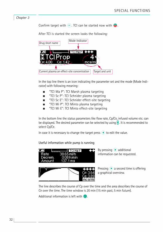
Confirm target with k. TCI can be started now with sf.
After TCI is started the screen looks the following:
In the top line there is an icon indicating the parameter set and the mode (Mode Indi-cator) with following meaning:
• “TCI Ma P”: TCI Marsh plasma targeting • “TCI Sc P”: TCI Schnider plasma targeting • “TCI Sc E”: TCI Schnider effect-site targeting • “TCI Mi P”: TCI Minto plasma targeting • “TCI Mi E”: TCI Minto effect-site targeting
In the bottom line the status parameters like flow rate, Cp/Ce, infused volume etc. canbe displayed. The desired parameter can be selected by using t . It is recommended toselect Cp/Ce.
In case it is necessary to change the target press l to edit the value.
Useful information while pump is running
The line describes the course of Cp over the time and the area describes the course ofCe over the time. The time window is 20 min (15 min past, 5 min future).
Additional information is left with C.
Chapter 3
SPECIAL FUNCTIONS
By pressing r additional information can be requested.
Pressing r a second time is offeringa graphical overview.
Drug short name
Target and unitCurrent plasma an effect-site concentration
Mode-Indicator

33
Chapter 3
SPECIAL FUNCTIONS
Finishing TCI
There are two possibilities to finish the TCI Therapy (reversion of anaesthesia or sedation):
• Set Target= 0 • Stop pump
It is recommended to simply stop the pump by pressing sf.
Pressing R the pump offers additional information – in this case the information is modified the following way:
After the therapy is ended there are two possibilities:
a) The pump may be used for TCI with the same drug again but with a new patient. In this case, cancel old therapy and use new disposables. b) The pump may go with the patient but in continuous mode (without TCI).
3.6 Barcoding
The barcoding functionality is included but initially not activated. Please contact yourlocal sales representative in case you like to use barcoding.
Pressing r again shows up thegraph.
In case a) press u in the menu - incase b) press d.
In both cases the “old” TCI needs tobe ended by c and selecting “Yes”in this screen by pressing u.

34
Chapter 3
SPECIAL FUNCTIONS
3.7 Piggyback Function
The piggyback-mode offers the possibility to interrupt the current (primary)infusion temporarily in order to administer a piggyback (secondary) infusion.Above the pump the piggyback-infusion line is connected with a Y-connector tothe administration set. The secondary infusion is supposed to be located approx.20 cm higher than the primary infusion. All infusion lines need to be completelyprimed. A back check valve has to be placed according to the drawing (see nextpage).
A precondition to start the piggyback function is that the pump is stopped.
Note: Please mind to set a VTBI of the primary and secondary infusion that corresponds to the size of the container. The piggyback infusion can be deliveredin continuous mode or dose over time mode only.
• Enter the rate manually or load into the pump via the dose rate calculation or the drug library. It is not possible to begin with the secondary infusion if the data for the primary infusion (rate and VTBI) is not set. To enhance comfort list of drugs can be adjusted to secondary mode by DrugLib.
• Select „Piggyback” from the Special Functions Menu and confirm with l.
• The change from the secondary to the primary infusion ("PIGY" to "PRIM") can be done manually or automatically. Correspondingly, if an automatic change is to be made automatically or manually is to be answered with u or d.
• The rate and VTBI of the secondary infusion can be loaded via the dose rate calculation, the drug library or are to be entered manually with q.
• Start secondary infusion by pressing sf. Device delivers the piggyback volume with the set piggyback rate.
Symbols in the headline of the run display ("PRIM" or "PIGY") will indicate if theprimary or secondary infusion is currently running.
When the piggyback volume is infused the pump automatically changes to theprimary infusion if this was selected. If the VTBI of primary infusion is infusedthe pump will continue with the KVO-rate respectively after the KVO-operationthe pump stops and activates an alarm. If a manual change from secondaryinfusion to primary infusion was selected, the pump will stop or continue withKVO after the secondary infusion is completed and the user manually has tochange via the menu item “Change to PRIM“ in the Main Menu to the primaryinfusion and start with sf.
Note: Infusion bag must contain residual volume for KVO after infused VTBI.
Note: Switching manually between primary and secondary infusion in the MainMenu is possible at any time while the pump is stopped. It is recommended tokeep the roller clamp of the non-active infusion closed.
The piggyback therapy can be repeated many times by changing the piggybackmedicament or by reset of the piggyback medicament.

35
Chapter 3
SPECIAL FUNCTIONS
• Go to „Set new Piggyback” in the Special Functions Menu and confirm with l.
Note: Resetting the data of the last secondary will also reset VTBI

36
Chapter 3
SPECIAL FUNCTIONS
3.8 Ramp and Taper Mode
The Ramp and Taper Mode is designed to deliver infusions with gradual ramp up andtaper down rates. The pump automatically calculates the rate increase and decreaserequired to match the total volume, time and ramp up/ramp down time parameters. Itconsists of 3 phases.
• Ramp phase: the pump rate is linearly increased until it reaches a predefined rate (plateau rate) in a predefined time (Up-Time) • Continuous phase: the plateau rate is used as a continuous infusion • Taper phase: the pump rate is decreased linearly after the continuous phase until the KVO rate is reached or pump is stopped in a predefined time (Down-Time)
Example:
Ramp and Taper should only be performed by an experienced user that isfamiliar with the principles of the Ramp and Taper function and properly trainedin using the present device.
Note: The active Ramp and Taper function is always symbolised with an charac-teristical symbol in the Display ( / / ).
Note: Bolus function is disabled for Ramp and Taper Mode.
Set Profile Parameters: The therapy can be started directly via the drug library or viathe Main Menu/Special functions.
Starting Ramp and Taper via Drug Library:
Note: Ramp and Taper settings have been configured in the Drug List Managerbefore and have been uploaded into the pump.
• Switch on pump with o and wait until self-check is finished.

37
• Insert disposable and use the drug library according to the Instructions for Use.
• Select the desired drug with t and press l.
The pump now lists the possible therapy profiles.
• Select “Ramp and Taper Mode” with t and press l. The therapy settings for “Ramp and Taper Mode” are shown on the display.
• To change the values, press l to change and k to confirm.
The pump can be started now by pressing sf.
Starting Ramp and Taper via Special Function Menu: • Switch on pump with o and wait until self-check is finished.
• Insert disposable.
• Go to Special Functions Menu and select Ramp and Taper.
• Press l to enter parameters and k to confirm.
• After entering all desired parameters the pump can be started by pressing sf.
The status of the therapy is shown in the upper part of the display of the pumpby the icon for “Ramp and Taper Mode”.
The screen shows the following:
Ramp phase
Continuous phase
Taper phase
Note: After starting infusion it is only possible to change rates, time and VTBI inthe continuous phase.
The pump now linearly increases the rate in the predefined time until it reaches the plateau rate andthen automatically switchesto continuous phase.
The pump continuously infusesthe same rate for a predefinedtime and then automaticallyswitches to taper phase.
The pump linearly decreases therate in the predefined timeuntil it reaches the KVO rate
SPECIAL FUNCTIONS
Chapter 3

38
Chapter 3
SPECIAL FUNCTIONS
By editing (increasing/decreasing) the plateau rate, the therapy is recalculated. Withthe increase/decrease of the plateau rate the volumes in the ramp phase, the conti-nuous phase and the taper phase are increased/decreased. The continuous phase isshortened/prolonged to infuse the VTBI still completely with the end of the taper phase.
By editing the Ramp/Taper-Time, the therapy is recalculated. The Continuous Phase isextended/shortened to infuse the VTBI still completely until the end of the Taper phase.
By increasing/decreasing the VTBI, the continuous phase is prolonged/shortened to infuse the new entered VTBI completely with the end of the taper phase.
Note: The delivery of drugs can be stopped and started again in Ramp and TaperMode at any time by pressig sf. Ramp and Taper is stopped immediately without Taper phase and started without a new Ramp phase.
Immediate Taper Down
By chosing the Immediate Taper Down Function the therapy can be ended with a taperphase before the originally defined VTBI is completely infused.
• Press C during continuous phase.
• Use t to select Special Functions and press l.
• Select Immediate Taper Down Function and confirm with l.
• Edit taper time by using t and press k to confirm. The pump automatically changes to Taper phase and linearly decreases the rate.
3.9 Program ModeProgram Mode is for infusion requiring a non-standard delivery pattern. The userdefines a series of intervals (max. 12 intervals) by certain parameters (rate, time,volume) for each cycle.
The pump automatically gives each programmed period, one after the other.

39
Example:
Program Mode should only be performed by an experienced user being familiar withthe principles of the Program Mode function and properly trained in using the presentdevice.
Note: The active Program Mode function always displays this icon in the Display( ).
Note: Bolus function is disabled for Program Mode.
Set Profile Parameters: The therapy can be started directly via the drug library or viathe Main Menu/Special functions.
Starting Program Mode via Drug Library:
Note: Program Mode settings have been configured in the Drug List Managerbefore and have been uploaded into the pump.
• Switch on pump with o and wait until self-check is finished.
• Insert disposable and use the drug library according to Instructions for Use.
• Select the desired drug with t and press l.
• Select Program Mode with l.
In the following screen the user has to confirm the number of steps for thetherapy with k.
The settings for the steps of the infusion are shown on the display. These settings, configured in the Drug List Editor, need to be confirmed with r.
• To change the values, press l to change and k to confirm.
SPECIAL FUNCTIONS
Chapter 3

40
Chapter 3
SPECIAL FUNCTIONS
• Adjust VTBI with q.
The pump can be started now by pressing sf.
Starting Program Mode via Special Function Menu: • Switch on pump with o and wait until self-check is finished.
• Insert disposable.
• Go to Special Functions Menu and select Program Mode.
• Press l to enter parameters and k to confirm.
• Adjust VTBI with q.
After entering all desired parameters the pump can be started by pressing sf.
In the upper part of the display the icon for “Program Mode” appears.The screen shows the following:
Only the VTBI may be changed during an infusion that is running.
• Press C to check upcoming Program Mode intervals in Main Menu.
It is possible to cancel one step of the running therapy. All following steps inthe programmed sequence persist.• Go to Main Menu by pressing C.
• Use t to navigate through the Main Menu and select Current with l.
• For checking upcoming intervals press C.
• Select "Program Parameters" with l.
• Go through all interval steps with r.
Note: The delivery of drugs can be stopped and started again in the ProgramMode at any time by pressing sf.
Number of cycles is defined by VTBI. Take care to set the VTBI in the correctrelation to the volume of one Cycle. VTBI may needs to be adjusted afterChanging the intervals.
The Main menu informs about the current interval. The configured parameterscan be checked by Program Parameter Menu in Main.
3.10 Intermittent Mode
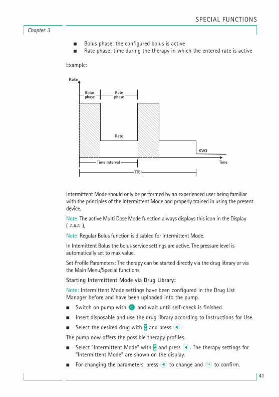
The Intermittent Mode consists of 2 phases. This phases will be repeated.
The pump infuses the predefined rate in the predefined time for the currentstep.
41
• Bolus phase: the configured bolus is active • Rate phase: time during the therapy in which the entered rate is active
Example:
Intermittent Mode should only be performed by an experienced user being familiarwith the principles of the Intermittent Mode and properly trained in using the presentdevice.
Note: The active Multi Dose Mode function always displays this icon in the Display( ).
Note: Regular Bolus function is disabled for Intermittent Mode.
In Intemittent Bolus the bolus service settings are active. The pressure level is automatically set to max value.
Set Profile Parameters: The therapy can be started directly via the drug library or viathe Main Menu/Special functions.
Starting Intermittent Mode via Drug Library:
Note: Intermittent Mode settings have been configured in the Drug ListManager before and have been uploaded into the pump.
• Switch on pump with o and wait until self-check is finished.
• Insert disposable and use the drug library according to Instructions for Use.
• Select the desired drug with t and press l.
The pump now offers the possible therapy profiles.
• Select “Intermittent Mode” with t and press l. The therapy settings for “Intermittent Mode” are shown on the display.
• For changing the parameters, press l to change and k to confirm.
SPECIAL FUNCTIONS
Chapter 3
42
Chapter 3
SPECIAL FUNCTIONS
Note: Bolus rate is calculated by editable parameters. These parameters have tobe checked by the user before starting the infusion.
The pump can be started now by pressing sf.
Starting Intermittent Mode via Special Function Menu: • Switch on pump with sf and wait until self-check is finished.
• Insert disposable.
• Go to Special Functions Menu and select Intermittent Mode.
• Press l to enter parameters and k to confirm.
After entering all desired parameters the pump can be started by pressing sf.
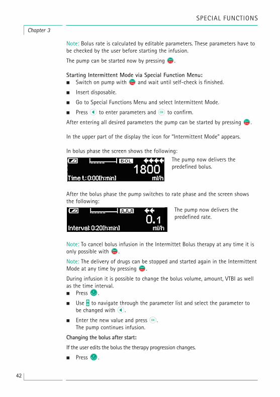
In the upper part of the display the icon for “Intermittent Mode” appears.
In bolus phase the screen shows the following:
After the bolus phase the pump switches to rate phase and the screen showsthe following:
Note: To cancel bolus infusion in the Intermittet Bolus therapy at any time it isonly possible with sf.
Note: The delivery of drugs can be stopped and started again in the IntermittentMode at any time by pressing sf.
During infusion it is possible to change the bolus volume, amount, VTBI as wellas the time interval.• Press C.
• Use t to navigate through the parameter list and select the parameter to be changed with l.
• Enter the new value and press k. The pump continues infusion.
Changing the bolus after start:
If the user edits the bolus the therapy progression changes.
• Press C.
The pump now delivers the predefined bolus.
The pump now delivers thepredefined rate.
43
• Use t to select Bolus and press l.
• Change Bolus by using t and press k to confirm. The pump automatically recalculates all other settings of the therapy.
Changing the time interval after start:
If the user edits the time interval the therapy progression changes.
• Press C.
• Use t to select Interval and press l.
• Change Interval by using t and press k to confirm. The pump automatically recalculates all other settings of the therapy.
3.11 Dose Over TimeDose Over Time is used to administer a specific dose of antibiotics in a specifictime. Dose Over Time is an own therapy and cannot be used in combinationwith another therapy except Piggyback. It can only be activated via the DrugList Manager. It can be used for standard infusion and/or piggyback.
The active Dose Over time function is always symbolised with a characteristicalsymbol in the Display ( ). If besides DOT the piggyback therapy is active, acombined symbol for both therapies will be displayed ( ).
Note: Dose Over Time should only be performed by experienced users beingfamiliar with the principles of the Dose Over Time function and properly trainedin using the present device.
The infusion rate in Dose Over Time can not be changed. This parameter is aresult of the total dose and the infusion time setting. Directly, after the Drugselection, the infusion time and the total dose intended to be infused have to beset. If the drug library contains default values for these parameters, the defaultvalues are used as preset values.
If changes are necessary during infusion, the delivery can be controlled bychanging the time. The pump calculates the new rate by using the remainingtotal dose and the remaining time. In the Main Menu total dose, time and VTBIcan be changed, also during RUN-Mode. Other parameters (dose rate, basal rate,concentration, patient weight and patient height) cannot be changed.
Note: The KVO function and Bolus function are disabled during Dose Over Time.
Note: The feature Dose Over Time always requires the usage of dosing units (i.e.,mg or mg/kg patient weight).
Before using Dose Over Time contact your local B. Braun representative!Starting Dose Over Time via Drug Library:
Note: Dose Over Time settings have been configured in the Drug List Manager
SPECIAL FUNCTIONS
Chapter 3
44
before and have been uploaded into the pump.• Switch on pump with o and wait until self-check is finished.
• Insert disposable and use the drug library according to the Instructions for Use.
• Select a drug by using t and press l.
The pump now offers the possible therapy profiles. Select “Dose over Time” with t andpress l.
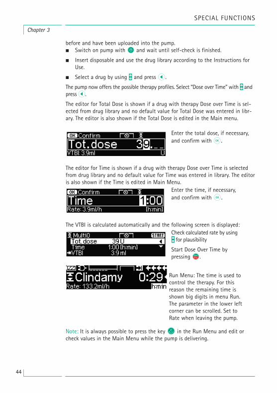
The editor for Total Dose is shown if a drug with therapy Dose over Time is sel-ected from drug library and no default value for Total Dose was entered in libr-ary. The editor is also shown if the Total Dose is edited in the Main menu.
The editor for Time is shown if a drug with therapy Dose over Time is selectedfrom drug library and no default value for Time was entered in library. The editoris also shown if the Time is edited in Main Menu.
The VTBI is calculated automatically and the following screen is displayed:
Note: It is always possible to press the key C in the Run Menu and edit orcheck values in the Main Menu while the pump is delivering.
Enter the total dose, if necessary,and confirm with k.
Enter the time, if necessary,and confirm with k.
Check calculated rate by usingt for plausibility
Start Dose Over Time bypressing sf.
Run Menu: The time is used tocontrol the therapy. For this reason the remaining time isshown big digits in menu Run.The parameter in the lower leftcorner can be scrolled. Set toRate when leaving the pump.
Chapter 3
SPECIAL FUNCTIONS

45
AUTOPROGRAMMING
Note: All normal pump functions remain in place when orders are received viaautoprogramming.
The pump can accept drug orders wirelessly from the EHR system or fromSpaceStation with SpaceCom. The workflow to accept an order wirelessly willvary depending on your EHR vendor.
• Using the hand held device or lap top, review the order and follow your hospital protocol for scanning the bag/syringe, pump, patient and nurse (optional).
• Once order is confirmed on the hand held or laptop, prompt EHR to send order directly to pump. The order will arrive and appear on the pump within 10 seconds.
• Ensure pump is in the Main Menu, passive mode or Standby.
• New Order message will appear with drug name and mode.
• Press k to accept or c key to cancel order and respond to prompt.
• Select Care Unit and Patient Profile as in Drug Library programming.
• Pump will search for Drug Library match.
Note: If no drug library match, which may be due to no matching name, concentration or dosing units, pump displays reason for no match and depending onyour hospitals configuration either allows manual programming outside the drug library or rejects order completely. An order that is confirmed outside the drug librarywill have a triangle with an exclamation point on display to indicate there are no druglibrary settings.
• Scroll to each value to confirm using q arrow keys.
AUTOPROGRAMMING
Chapter 4

46
Note: Order may be cancelled prior to confirming order.
• Once all values are confirmed, the Main Menu is displayed.
Note: Soft Limit alert will be issued if value exceeds any soft limits set in druglibrary, soft limit may be overridden or value re-programmed per institutionalpolicy. Order will be rejected if hard limit is exceeded. (except in circumstancewhere pump service program is not set to perform drug library match for auto-programming).
For PRIMary Orders (Either 'Continuous' oder 'Dose over Time'):
Note: The first order sent send as 'Continuous' is always considered as thePRIMary infusion, subsequent orders will be considered PIGGYback.
Note: Order sent as 'Dose over Time' is always considered the PRIMary infusion,no subsequent order can be received. Additional, no updates can be received for'Dose over Time'.
• Press Start/Stop key sf to start infusion.
Updates to Current Primary Infusion
Updates may be received for PRIMary infusions while pump is running or stopped andwhile in PRIMary or PIGGYback.
While in PRIMary:
• Update icon will appear on display, follow on screen prompts to accept or cancel the order. Confirmation screen will indicate both OLD and NEW value for parameter(s) that changed.
Chapter 4
AUTOPROGRAMMNG

47
While in PIGGYback:
• Message will appear on top of display indicating update is available for PRIMary.
• Press M key to view order.
• Follow prompt, pressing sf to accept order or c key to cancel and hold order for later.
New Primary Infusion:
• To accept a new PRIMary order, stop infusion and clear current PRIMary infusion by pressing c key and responding “yes” to clear current infusion.
PIGGYback Orders:
Orders received after PRIMary has been set will be for PIGGYback infusions, follow prompts on screen to stop the PRIMary to accept the PIGGYback order.
• Confirm order values as above for PRIMary orders.
• Respond to prompts to check bag height and clamps prior to startingPIGGYback.
New PIGGYback order while PIGGYback is Infusing:
• Follow display prompts to stop current infusion.
Note: A PIGGYback order may be held for later by pressing c key to cancelorder and answering yes to “hold for later”.
Chapter 4
AUTOPROGRAMMING

48
Note: Changing values on any incoming order may only be done after confir-ming all values. Once all values are confirmed you may scroll to any value andopen editor with l to change value. Alternately, order may be cancelled andrequest made for revised order to be sent.
Note: If pump is placed in standby while order is pending new order will flashon top of stand by display, press M key to accept order (pump will come out ofstandby).
Chapter 4
AUTOPROGRAMMNG
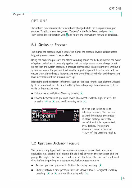
49
Chapter 5
OPTIONS
OPTIONS
The options functions may be selected and changed while the pump is infusing orstopped. To edit a menu item, select “Options” in the Main Menu and press l.Then select desired function with t and follow the Instructions for Use as described.
5.1 Occlusion Pressure
The higher the pressure level is set at, the higher the pressure level must rise beforetriggering an occlusion pressure alarm.
Using the occlusion pressure, the alarm sounding period can be kept short in the eventof system occlusions. It generally applies that the set pressure should always be sethigher than the system pressure. If pressure alarms occur in a pressure level without asystem occlusion, the pressure level must be adjusted upward. In order to be able toensure short alarm times, a low pressure level should be started with and the pressurelevel increased until the infusion starts up.
Depending on the different influences, such as the tube length, tube diameter, viscosi-ty of the liquid and the filter used in the system set-up, adjustments may need to bemade to the pressure level..
• Enter pressure in Options Menu by pressing l.
• Choose between nine pressure levels (1=lowest level; 9=highest level) by pressing l or r and confirm entry with k.
5.2 Upstream Occlusion Pressure
The device is equipped with an upstream pressure sensor that detects an occlusion (e.g. closed roller clamp, kinked line) between the container and thepump. The higher the pressure level is set at, the lower the pressure level mustdrop before triggering an upstream occlusion pressure alarm.
• Access upstream pressure in Options Menu by pressing l.
• Choose between nine pressure levels (1=lowest level; 9=highest level) by pressing l or r and confirm entry with k.
The top line is the currentinfusion pressure. The buttomdashed line shows the pressu-re alarm setting, currently 5out of 9 which is representedby 5 dashed. The pictureshows a current presure of ~ 30% of the pressure level 5.

50
OPTIONS
Chapter 4
5.3 Data Lock
The data lock function protects the device against unauthorized access. It is recommended to adapt the four digit code for level 1 and 2 from the defaultsetting (9119), using the service program. There are three security levels.
Level 1:A modification of values as well as a bolus application are not possible but achange of the disposable can be conducted. It is possible to navigate through allmenus and status data can be checked. Starting, interrupting and switching thepump off is possible.
Level 2:This level has the same performance characteristic as described under level 1and additional will not allow the change of disposable. In order to prevent adata lock alarm the correct code must be entered within 20 sec after the pumpwas stopped. Changing the disposable and switching the pump off is onlypossible after the code was entered.
Level 3:This level will allow starting and stopping the pump as well as switching off.The code for this level may be different for each drug and is defined in the druglist. A change of the disposable, however, is possible by using the code definedfor the other levels. An overview about the differences between the levels 1, 2and 3 is given by the following table.
Activation of the function:
• Open data lock in Options Menu with l.
EventChange of disposable
Level 1 Level 2 Level 3
Change of parameters O OO
O
Stop of infusion % Switching off pump / Standby O OPCA bolus with pump-based bolus button
= possible | O = not possible | % = followed by standby-alarm
O O
Customisable screen O O
Acoustic feedback of demanded boli O O
Indicates denied PCA boli O
Start of infusion
O with code forlevel 1/2

51
Chapter 4
OPTIONS
• Select between level 1, 2 or 3 (if activated) with l and r and confirm with k.
• Enter code with q and press k in order to activate data lock.
Changes to the protected values and the bolus function which are marked withy are only possible after entering the code. After 20 sec in the Main Menu,Status Menu, Special Functions Menu and Options Menu the lock will be acti-vated again. If the wrong code is entered twice the pump will switch into thelast menu. If the wrong code is entered twice again the pump will go into anaudible alarm, a nurse call will go off and the yellow LED blinks. If a targetvalue was reached while data lock is active a new start of the pump is only possible after entering the code.
In order to deactivate the function, select “Off” in the data lock, press k, enterthe code and press k again.
5.4 Bolus Rate
• Open bolus rate in Options Menu with l.
• Change bolus rate with q and confirm setting with k.
Note: Set bolus rate according to therapy requirements. Take care not to overdose!Given a bolus rate of 1200 ml/h, e.g. 0.33 ml are reached within just one second.
5.5 KVO-Mode
The pump can continue the infusion with a preset KVO-rate after a preselectedVTBI/time has passed (see "Technical Data"). The duration of the KVO delivery is selected in the service program.
• Open the KVO-mode in the Options Menu with l.
• Answer the Yes/No question with u to enable the KVO-mode.
5.6 Contrast / Display Light / Keypad Light
Contrast as well as display- and keypad light can be adjusted individually according tothe lighting conditions.
• Open contrast/display light/keypad light in Options Menu by pressing l.
• Choose between 9 contrast- and display light levels with l or r and confirm with k.

52
5.7 Alarm Volume
Chose between 9 different alarm volume levels.
• Open alarm volume in Options Menu with l.
• Set volume with l or r and confirm entry with k.
5.8 Date / Time
• Open date/time in the Options Menu with l.
• Modify date and time with q and confirm the setting with k.
5.9 Macro Mode
The infusion rate appears larger on the display when the macro mode is activated andthe pump is infusing.
• Open macro mode in Options Menu with l.
• Answer Yes/No question by pressing u to activate the macro mode.
For quick activation of macro mode: Press and hold rwhile the pump is infusinguntil the font size changes.
5.10 Language
This function enables a change of the pump language.
• Open language in the Options Menu with l.
• Select language with t then press l.
• Confirm Yes/No question with u.
Chapter 5
OPTIONS
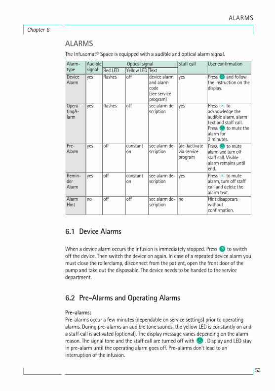
53
Chapter 6
ALARMS
ALARMSThe Infusomat® Space is equipped with a audible and optical alarm signal.
6.1 Device Alarms
When a device alarm occurs the infusion is immediately stopped. Press o to switchoff the device. Then switch the device on again. In case of a repeated device alarm youmust close the rollerclamp, disconnect from the patient, open the front door of thepump and take out the disposable. The device needs to be handed to the service department.
6.2 Pre-Alarms and Operating Alarms
Pre-alarms:Pre-alarms occur a few minutes (dependable on service settings) prior to operatingalarms. During pre-alarms an audible tone sounds, the yellow LED is constantly on anda staff call is activated (optional). The display message varies depending on the alarmreason. The signal tone and the staff call are turned off withC . Display and LED stayin pre-alarm until the operating alarm goes off. Pre-alarms don't lead to an interruption of the infusion.
Alarm-typeDeviceAlarm
yes flashes off device alarmand alarmcode(see serviceprogram)
yes Press O and followthe instruction on thedisplay.
Opera-tingA-larm
yes flashes off see alarm de-scription
yes
Pre-Alarm
yes off constanton
see alarm de-scription
(de-)activatevia serviceprogram
Press C to mutealarm and turn offstaff call. Visiblealarm remains untilend.
Remin-derAlarm
yes off constanton
see alarm de-scription
yes Press k to mutealarm, turn off staffcall and delete thealarm text.
AlarmHint
no off off see alarm de-scription
no Hint disappearswithout confirmation.
Audiblesignal Red LED
Optical signalYellow LED Text
Staff call User confirmation
Press k toacknowledge theaudible alarm, alarmtext and staff call. Press C to mute thealarm for 2 minutes.

54
Display message Pre-alarm reason
“VTBI near end“ The preselected volume is nearly infused.
“Time near end“ The preselected time is almost over.
“Battery nearly empty“ The battery is almost discharged.
“KVO mode“ VTBI/time are reached and the pump continues the infusion at the KVO-rate.
A stopwatch on the display counts down the remaining time (depending on theservice program, between 0-30 min). After that, the pump changes to theoperating alarm.
The pre-alarms “VTBI near end“ (volume preselection) and “Time near end“ (timepreselection) can be deactivated via the service program.
Operating alarms:Operating alarms lead to an interruption of the infusion. An audible tonesounds, the red LED flashes and a staff call is activated. The display states "Alarm", the reason for the operating alarm and gives theoption to either confirm the alarm by pressing k or mute the alarm by pressing C. If the alarm is muted, the alarm message will remain on the screen until it is confirmed by pressing k. After 2 minutes, if the alarm hasnot been confirmed by pressing k, the audible tone will sound again. Thealarm tone, the alarm message, and the staff call (optional) are all cleared bypressing k. Corrections are to be made according to the alarm reason.
Display message Alarm reason
“VTBI infused “ The preselected volume was infused. Continue therapy or select new therapy.
“Time expired“ The preselected time has ended. Continue therapy or select new therapy.
“Battery empty“ The battery pack is discharged. Connect device with mains and/or exchange battery pack. The battery alarm will be on for 3 min. Then the pump will automatically turn off.
“Pressure high“ An occlusion occured in the system. The set pressure level was exceeded. A bolus reduction is automatically initiated by the pump. Check if tubing contains kinks or is damaged as well as IV- and filter patency. Increase occlusion pressure if necessary.
“KVO finished“ The KVO-time has ended. Continue therapy or set new therapy.
Chapter 6
ALARMS

55
Battery cover removed“ The battery cover is not properly engaged on the battery compartment. When pushing on the battery cover listen for “click”.
“Standby time expired“ The set standby time has ended. Set new time or continue with previously set therapy.
“No battery inserted“ It is not possible to use the pump without a battery pack. Turn off pump and insert battery pack according to description “Overview Infusomat® Space“.
“Drive blocked“ Stepper motor does not deliver due to excess pressure in the system. Interrupt patient connection and reinsert the line.
“Calibrate device“ Pump calibration data have changed (e.g. after an update). Recalibrate device via the service program.
“Drop sensor connection“ Contact to the drop sensor is interrupted while the pump is delivering. Check whether the drop sensor is correctly placed on the drop chamber. If necessary, replace the drop sensor or preselect VTBI/time and proceed with therapy.
“Check upstream“ The upstream sensor triggers an alarm. Check if roller clamp is closed or infusion line is kinked. If a drop sensor is connected the upstream alarm is deactivated.
“Air bubble "/"Accumulated air“ Air inside the system. Check the line for small air bubbles and disconnect from patient to repeat priming, if necessary.
“No drops“ The drop sensor does not detect any drops. The infusion container is empty, the roller clamp is closed, the drop sensor is not put on, check the line for obstructions, condensation on drop chamber (remove by shaking it).
"Too few drops" The number of fallen drops is lower than the preset rate. A negative pressure in a glass infusion container can be eliminated by opening the vent flap on the drop chamber. Check whether the infusion bottle is empty, the roller clamp is completely opened and whether there are any kinks in the line.
"Too many drops" The number of fallen drops is higher than the preset rate.
ALARMS
Chapter 6

56
Check the line for damage and make sure that the line is correctly inserted.
"Flow" Drop chamber is completely filled or leak in the system. Examine the line for damage and check the drop chamber.
“Data were reset” Therapy and pump settings could not be restored. Enter therapy again.
"Therapy data were reset" Therapy data could not be restored. Enter therapy again.
“Data Lock" An attempt was made to stop or switch the pump off without entering the code. Enter the correct code in order to continue the therapy respectively turning the pump off.
The red LED extinguishes with the acknowledgement of the alarm.
Caution: If a wrench ( ) is displayed and/or a yellow, red and blue LED blinkthen the pump is in the service mode and is not permitted to be used on a patient. Thepump must then be checked by a service technician.
6.3 Reminder Alarms
Reminder alarms only occur in two cases:
1. A line is inserted, the pump does not deliver, no value is edited and the device is not operated for two minutes. An acoustic tone sounds, the yellow LED is constantly on and a staff call is activated.
a) The display states “Reminder alarm!”
b) The display states “Config. not finished!”
Confirm alarm with K and continue to set therapy/Start Up configuration.
2. A value edition was started but not finished and confirmed. This is also possible with a missing disposable. An acoustic tone sounds, the display states “Value not accepted“, the yellow LED is constantly on and a staff call is activated. Confirm alarm with K and continue to set therapy.
6.4 Alarm Hints
If inproper entries are made the display states corresponding hints (e.g. “Bol.rate out ofrange”; “Download failed”; “The parameter can not be modified”).
ALARMS
Chapter 6

57
BATTERY OPERATION AND MAINTENANCE
Chapter 7
BATTERY OPERATION AND MAINTENANCE
The battery has an operating lifetime of 4 hours at 100 ml/h when new. For optimaltreatment of the battery, the device is equipped with protection against overchargeand deep depletion. The battery pack is charged by the pump during connection tomains. When disconnected from mains or in case of power failure, the pump automatically switches to battery power.
Note: Prior to a longer storage of the pump (> 5 months) the battery pack must becompletely charged and then removed from the pump. Before changing the battery, always disconnect the pump from the patient and switch off the device.
The battery status indicator is a trend display (low, medium, high). For more detailedinformation on the current battery capacity (operating time in hours and minutes)please refer to menu item “Batt. Cap.” in the Status Menu of the Infusomat® Space.
Caution: The display of the battery operating time on the pump is an approximate va-lue based on the current delivery rate. Changes in the delivery rate may affect the bat-tery operating time.
Disposable change procedures require a high power consumption. A sudden breakdown of the battery operating time can be possible with an aged battery. In this casethe battery has to be replaced by a new one.
If highly potent drugs are to be given over an extended time without mains power, it isrecommended to have a fully charged reserve pump at hand.
Note: In case of ESD, Pump may need plugged into wall outlet to re-start the battery.
Attention: If the battery module is stored for long periods of time outside the pump, itis recommended to fully charge the battery and store it at room temperature.
Caution: Batteries may explode or leak if they are opened or incinerated. Consider dis-posal directions!
Important information for battery self-check:
If the battery symbol is blinking during mains operation, the battery has less then 30minutes remaining capacity.
In this case, the pump should not be disconnected from mains. If it is necessary to dis-connect the pump from mains power for urgent reasons, the user should check to en-sure if the battery capacity is sufficient for the proposed use. When the battery symbolblinks permanently (>1h), the battery must be checked by a technician and replaced ifnecessary.
Directions for optimal battery use:
The actual battery life may vary due to • ambient temperature • varying load (e.g. frequent boluses).
58
The optimal life time of a battery pack will only be reached if it's completely discharged from time to time. A maintenance mode which conducts this battery maintenance is built in. This function should be activated once a month. Furthermore:
• If a battery, which is not completely discharged, is charged several times, its capacity can be reduced. • Under normal temperature conditions a battery can be charged and discharged approx. 500 times before its lifetime decreases. • When the pump is not connected to mains power the battery discharges itself slowly. This can occur even when the pump is not operating. • The battery operating time can only be realized if the pump operates continuously with a fully charged battery at room temperature.
Battery maintenance:
To accurately balance the battery capacity a cyclical battery maintenance is necessary.The frequency of battery maintenance may be set in the service tool. The battery main-tenance mode detects a possible capacity loss (e.g. through ageing of the battery pack)and then the capacity/running time will be calculated anew. After a longer storage time or a longer operation without battery maintenance it can happen thatthe battery pre-alarm time can no longer be maintained. In this case it is necessary toperform a battery maintenance.To initiate the discharge process the message „Battery maintenance“ and the k-keywill be displayed after switching the pump off. By pressing k and u the dischargeprocess will start. The process is interrupted by switching the pump on again. If thebattery maintenance is to be continued a new activation is necessary. After completelydischarging the battery it will be completely charged again. The total duration of thebattery maintenance process takes approx. twelve hours.
Caution: Please take into account that, if the battery maintenance has not been completed there is a possibility of a reduced battery operating time.
Replacing batteries:
The Battery Pack SP can be exchanged by any user. No special qualification is required.
All rechargeable batteries exhibit a reduction in capacity as they age. This aging is de-pendant on several factors including charging cycles, temperature and battery usage.
It is recommended to periodically check the function of the battery. A battery shouldno longer be used if a change of disposable leads to a “Battery nearly empty“ or a “Bat-tery empty“ alarm when it is fully charged.
Caution: Batteries may explode or leak if they are opened or incinerated. Consider disposal directions!
BATTERY OPERATION AND MAINTENANCE
Chapter 7

59
START UP GRAPHS AND TRUMPET CURVES
Chapter 8
The graphs show the accuracy/uniformity of flow in relation to time. They allowfor the following:The delivery behaviour or delivery precision is essentially influenced by the typeof the disposable used. Deviations from the technical data of the pump cannot beguaranteed as the manufacturer may change IV-set specification significant tosystem accuracy without prior notification.
System accuracy is +/- 5% typical by volume as measured using the trumpetcurve test method defined in IEC 60601-2-24 at rates of 1ml/h (23°C) and whenthe pump is used with recommended sets.
START UP GRAPHS AND TRUMPET CURVES
Trumpet CurvesMeasured values for second hour in each case.Measurement interval ∆t = 0.5 minObservation interval p x ∆t [min]
Start Up GraphsMeasurement interval ∆t = 0.5 minMeasurement duration T = 120 minFlow Qi (ml/h)
Start Up Graphs Trumpet Curves

60
TECHNICAL DATA
Type of unit Volumetric infusion pump
Classification (acc. to IEC/EN 60601-1) defibrillator-proof; CF equipment Protective Class II; Protective Class I in combination with SpaceStation
Class (acc. to Directive 93/42 EEC) IIb
Moisture protection IP 22 (fluid protected for horizontal usage)
External power supply: •Rated voltage Via B. Braun SpaceStation or optional mains adaptor (rated voltage 100 … 240 V AC~, 50/60 Hz) for stand alone operation • External low voltage 11 … 16 V DC via Connection Lead SP 12 V or via SpaceStation
Staff call Max. 24 V / 0,5 A / 24 VA (VDE 0834)
EMC IEC/EN 60601-1-2 / 60601-2-24
Time of operation 100 % (continuous operation)
Operating conditions: •Relative humidity 30 % … 90 % (without condensation) • Temperature +10 … +40 °C •Atmospheric pressure 500 … 1060 mbar
Storage conditions: •Relative humidity 20 % … 90 % (without condensation) • Temperature -20 … +55 °C •Atmospheric pressure 500 … 1060 mbar
Type of battery pack (rechargeable) NiMH
Operating time of rechargeable battery Approx. 4 hours at 100 ml/h
Recharging time Approx. 6 hours
Weight Approx. 1.4 kg
Dimensions (W x H x D) 214 x 68 x 124 mm
Volume preselection 0.1 - 99.99 ml in increments of 0.01 ml 100.0 – 999.0 ml in increments 0.1 ml 1000 – 9999 ml in increments 1 ml
Time preselection 00:01 – 99:59 h
Accuracy of set delivery rate ± 5 % according to IEC/EN 60601-2-24
Max. Volume in case of single fault condition For incorrect dosages of 1,4 ml due to malfunctions of the device the pump will automatically shut off
Technical inspection (safety check) Every 2 years
TECHNICAL DATA
Chapter 9

61
Administration Set Change Interval Pumping accuracy is maintained for a minimum of 96 hours.
Multiple lines connected to one Connecting multiple infusion lines withpatient port different flow rates may affect the rate for all infusions past the point of connection.
Rate increments 0.1 - 99.99 ml/h in increments of 0.01 ml/h 100.0 - 999.9 ml/h in increments of 0.1 ml/h 1000.0 - 1200 ml/h in increments of 1 ml/H
Accuracy of bolus infusion typ. ± 5 % as of a bolus volume > 1 ml
KVO-rate Delivery rate ≥ 10 ml/h: KVO-rate 3 ml/h Delivery rate < 10 ml/h: KVO-rate 1 ml/h Delivery rate < 1 ml/h: KVO-rate = set rate (default setting 0.1 ml/h)
Computer connection USB connection in combination with B. Braun interface lead CAN SP (8713230) including electrical insulation. Please pay attention to safety notices.
Air detector Technical sensitivity: Detection of air bubbles ≥ 0.01 ml Alarm triggering: Single bubble alarm: 0.02 – 0.3 ml (default 0.3 ml) Cumulative air alarm: 0.5 – 3.8 ml/h (default 1.5 ml/h) Resolution: 0.01 mlSensitivity upstream sensor 9 levels from -0.12 bar to -0.21 bar (pressure reduction)
Occlusion alarm pressures 9 levels up to 1.2 bar
Max. bolus after bolus reduction ≤ 0.2 mlAlarm volume 9 levels from 1 (59dBA) to 9 (74dBA)
00:2400:1500:07
[100 ml/h]
02:0601:1400:33
[25 ml/h]
46:5025:53
typ. 1.2typ. 0.7
09:07typ. 0.3[1 ml/h]
Occlusion pressure Time to occlusion alarm [min] at rate[bar]
Level 9Level 5Level 1
Chapter 9
TECHNICAL DATA
62
Chapter 9
TECHNICAL DATA
Mechanical occlusion pressure limitunder fault conditions Occlusion alarm pressure max. 2.1 bar (210 kPa). Maximum posts occlusion bolus volume 2ml.History protocol > 3000 last history entries 100 events for system diagnose. Refer to separate documents of the History Viewer for closer information.
• Use only pressure proof and compatible disposable items (min. 2 bar/1500 mm Hg) to avoid influencing performance data - which would result in impairing patient safety.
• Only use combined with approved devices/accessories by the manufacturer, otherwise this may lead to higher emission or reduced immunity.
• Use only compatible combinations of equipment, accessories, working parts and disposables with luer lock connectors.
Essential Performance for Infusion pumps:
• Infusion of liquids without variation of infusion rate
• Pressure limitation as protection from the bursting of the infusion line
• Protection from air-infusion
• Protection against unintended bolus volumes and occlusion (added by IEC
60601-2-24) • Alarm signal of high priority (added by IEC 60601-2-24)
Note: The technical data stated in this Instructions for Use manual weredetermined with the Infusomat® Space lines as of "Type Standard" (870 0036 SP).These technical data can change when using set configurations.

63
TECHNICAL DATA
EMC (ELECTROMAGNETIC COMPATIBILITY)
Chapter 9
Guidance and manufacturer’s declarartion on electromagnetic compatibility
Emissions test
Guidance and manufacturer’s declaration – electromagnetic emission
The Space System is intended for use in the electromagnetic environment specified below. Thecustomer or the user of the Space System or any component should assure that it is used in suchan environment.
RF emissions CISPR 11
Compliance
Group 1
Electromagnetic environment guidance
The Space System uses RF energy only for its internalfunction. Therefore, its RF emissions are very low andare not likely to cause any interference in nearby electronic equipment.If WLAN-Module is installed within Battery module(8713182A) or WLAN USB Stick for SpaceCom(8713185) is used RF energy is transmitted by theSpace System.Refer to technical data of Battery-Pack SP with WifiIUF and/or SpaceStation and SpaceCom for details.
RF emissions
CISPR 11
Harmonic emissions IEC 61000-3-2
Class B (Note 2)
applicable only forSpaceStation
Class A
Voltage fluctuations /flicker emissions
IEC 61000-3-3
Note 1: Maximum emissions are measured with a complete system (SpaceStation and components).
Note 2: If Class A equipment is attached to the Space System, the Space System will become ClassA too. This equipment/system may cause radio interference or may disrupt the operation of nearbyequipment. It may be necessary to take mitigation measures, such as re-orienting or relocating theSpace System or shielding the location.
Complies
The Space System or any component is suitable foruse in all establishments, including domestic establishments and those directly connected to thepublic low-voltage power supply network that supplies buildings used for domestic purposes.

64
Chapter 9
TECHNICAL DATA
Note: Different test values of IEC 60601-2-24 are marked in the table. At the test values no dangerous disturbances occurred at the lower test values of IEC 60601-1-2.
Immunity test
Guidance and manufacturer’s declaration – electromagnetic immunity
The Space System is intended for use in the electromagnetic environment specified below. The customer or the user of the Space System or any component should assure that it is used in suchan environment.
Electrostaticdischarge (ESD)according IEC60601-4-2
contactIEC 60601-1-2:±6KVIEC 60601-2-24:±8KV
airIEC 60601-1-2:±8KV IEC 60601-2-24: ±15KV
±6KV no disturbances
±8KV stop with alarm possible
±8KV no disturbances
±15KV stop with alarmpossible
Floors should be wood, concrete or ceramic tile. If floors are covered withsynthetic material, the relativehumidity should be at least 30 %.
Electrostatic transient / burstaccording IEC61000-4-4
± 2 kV for powersupply lines
± 1 kV for input/output lines
±2KV
±1KV
A/C power quality should bethat of a typical commercial orhospital environment.
Surge according IEC61000-4-5
differential mode±1KV
common mode ±2KV
±1KV
±2KV
A/C power quality should bethat of a typical commercial orhospital environment.
Power frequency(50/60 Hz)magnetic fieldaccording IEC61000-4-8
3 A/m 400 A/m Power frequency magneticfields should be at levels characteristic of a typical location in a typical commercial or hospital environment.
Voltage dips, shortinterruptions andvoltage variationson power supplyinput linesaccording IEC61000-4-11
< 5 % UT (>95 % dip in UT )for 0,5 cycle
40 % UT (60 % dip in UT )for 5 cycles
70 % UT (30 % dip in UT )for 25 cycles
< 5 % UT (>95 % dip in UT )for 5 sec
<5% UTfor 5 s(>95% dip)
complies by use of internal battery
A/C power quality should bethat of a typical commercial orhospital environment. If theuser of the Space Systemrequires continued operationduring long time A/C powerinterruptions, it is recommended that the SpaceSystem or component be powered from an uninterruptible power supply ora battery.
test level IEC 60601-1-2IEC 60601-2-24
Compliance level Electromagnetic environment – guidance

65
TECHNICAL DATA
Chapter 9
radiated electromagneticRF fields according IEC 61000-4-6
radiated electromagneticRF fields according IEC 61000-4-3
IEC 60601-1-2: 3 Veff normal and10Veff in ISM frequency band
IEC 60601-2-24:10 Veff150KHz to 80MHz
10 V/m80 MHz to 2,5 GHz
10Veff150KHz to 80MHz
10 V/m80 MHz to 3 GHz
Portable and mobile RF communications equipment shouldbe used no closer to any part of theSpace System or it’s components,including cables, than the recommended separation distancecalculated from the equation applicable to the frequency of thetransmitter.
Recommended separation distance
d = 1,2 √PField strengths should be less then10V/m
d = 1,2 √P80 MHz to 800 MHz
d = 2,3 √P 800 MHz to 2,5GHz
where p is the maximum outputpower rating of the transmitter inwatts (W) according to the transmit-ter manufacturer and d isthe rec-ommended separationdistance in meters (m).
Field strengths from fixed RF transmitters, as determined by anelectromagnetic site survey, shouldbe less than the compliance level ineach frequency range.
Interference may occur in the vicinity of equipment marked withthe following symbol:
Immunity test
Guidance and manufacturer’s declaration – electromagnetic immunity
The Space System is intended for use in the electromagnetic environment specified below. The customer or the user of the Space System or any component should assure that it is used in suchan environment.
test level IEC 60601-1-2 IEC 60601-2-24
Compliance level
Electromagnetic environment - guidance
NOTE 1: At 80 MHz and 800 MHz, the higher frequency range applies.
NOTE 2: These guidelines may not apply in all situations. Electromagnetic propagation is affected byabsorption and reflection from structures, objects and people.
NOTE 3: See next page.

66
TECHNICAL DATA
Chapter 9
NOTE 3: Different test values of IEC 60601-2-24 are marked in the table. At these test values nodangerous disturbances are allowed while at the lower test values of IEC 60601-1-2. Field strengthsfrom fixed transmitters, such as base stations for radio (cellular/cordless) telephones and land mobileradios, amateur radio, AM and FM radio broadcast and TV broadcast cannot be predicted theoreticallywith accuracy. To assess the electromagnetic environment due to fixed RF transmitters, an electro-magnetic site survey should be considered. If the measured field strength in the location in which theSpaceSystem is used exceeds the applicable RF compliance level above, the Space System should beobserved to verify normal operation. If abnormal performance is observed, additional measures may benecessary, such as re-orienting or relocating the Space System.
rated power of theratio transmitter
W
Separation distance according to frequency of transmitter
m
The Space System is intended for use in an electromagnetic environment in which radiated RF disturbances are controlled. The customer or the user of the Space System or component can helpprevent electromagnetic interference by maintaining a minimum distance between portable andmobile RF communications equipment (transmitters) and the Space System as recommended below,according to the maxi-mum output power of the communications equipment
150 kHz bis 80 MHz 1,2√P
80 MHz bis 800 MHz 1,2√P
800 MHz bis 2,5 GHz 2,3√P
NOTE 1: For transmitters rated at a maximum power output not listed above, the recommended separation distance (d) in meters (m) can be determined using the equation applicable to the frequen-cy of the transmitter, where (P) is the maximum output power rating of the transmit-ter in watts (W)according to the transmitter manufacturer.
NOTE 2: An additional factor of 10/3 is used in calculating the recommended separation distance fortransmitters in the frequency range 0.15 MHz to 2.5 GHz to decrease the likelihood that mobile/portable communications equipment could cause interference if it is inadvertently brought into patient areas.
NOTE 3: These guidelines may not apply in all situations. Electromagnetic propagation is affected byabsorption and reflection from structures, objects and people.
0,01 0,12 0,23
0,1 0,38 0,73
1 1,2 2,3
10 3,8 7,27
100 12
0,12
0,38
1,2
3,8
12 23

67
WARRANTY / TRAINING / TSC* / SERVICE / DISINFECTING / DISPOSAL
Chapter 10
WARRANTY / TRAINING / TSC* / SERVICE /DISINFECTING / DISPOSAL
Responsibility of the Manufacturer
The manufacturer, assembler, installer or importer is responsible for the effectson safety, reliability and performance of the equipment only if:
• assembly operations, extensions, re-adjustments, modifications or repairs are carried out by authorized personnel, • the electrical installation of the relevant room complies with the appropriate requirements (e.g. VDE 0100, 0107 and/or the IEC-publications resp. national requirements), • the equipment is used in accordance with the Instructions for Use and • the Technical Safety Checks are carried out regularly.
Warranty
B. Braun provides 24 months warranty, as from the date of delivery, for everyInfusomat® Space (12 months for every Battery-Pack SP). This covers repair orreplacement of parts damaged as a result of design/manufacturing errors ormaterial defects. Modifications or repairs to the unit undertaken by theuser/operator or by third parties invalidate the warranty.
The warranty does not cover the following: Elimination of faults attributable to incorrect/unauthorized handling, or tonormal wear and tear.
Defective rechargeable battery packs can be returned to B. Braun for furtherdisposal.
WARNING: Do not modify this equipment without authorization of the manufacturer.
Separate collection for electrical and electronic equipment (currently applicable to EU community only).
Training
B. Braun offers a training. Please ask your local representative for furtherdetails.
The CE mark confirms that thismedical productcomplies with the“Council Directiveon Medical Devices93/42/EEC” dated14th Junde 1993.
B. Braun Melsungen AG

68
Technical Safety Check* / Service
The Technical Safety Check is recommended to be carried out every 2 years andshould be documented. Servicing work must be carried out exclusively by trained personnel.
Check regularly
Check for cleanliness, completeness and damage. Use only according toInstructions for Use. During an exchange interval of the disposable the pumphas to perform a self-test. Check the following items each time the pump isswitched on: self-check, audible alarm, process- and alarm control indication.
Disinfecting
Caution: Before disinfecting the pump, always disconnect the pump from the patient, switch off the device and disconnect from power and other devices (e.g. staff call).
Clean all exposed surfaces using a clean, soft, lint-free cloth dampened with amild cleaning solution of warm, soapy water. Make sure to remove any visibleresidue from all surfaces prior to disinfecting. Do not spray disinfectants direct-ly on the pump, use a soft, low lint cloth dampened but not saturated with pro-duct. After cleaning allow device to dry for at least 20 minutes prior to use. Theline guide element can be removed using a pointed object (ballpoint pen) inser-ted in the lower right corner. The cover can then be immersed, to be cleaned,wipe “fingers” with a soft cloth. Wipe magnifying- and displayglas on front ofpump door only with a soft cloth.
Note: Do not use Hexaquart® or other alkylamine containing disinfectants.
Recommended: disinfectant for wiping available from B. Braun: Meliseptol®Foam pure, Melsitt 10% and Melsept SF 10%.
Note: Keep instrument upright and do not allow any part of instrument to become saturated with or submersed in fluid during cleaning operation.
Do not allow moisture or detergents to come into contact with the electricalconnections of the device (P2 or P3 connectors) or any device openings. To
Chapter 10
WARRANTY / TRAINING / TSC* / SERVICE / DISINFECTING / DISPOSAL

69
reduce the likelihood of moisture ingress into the electrical connectors, the P2connector of a power supply or combi cable may be used to cover the connections during cleaning operations. Ensure that any connectors used tocover are not connected to a wall outlet or other electrical source. Once thecleaning has been completed, remove the connector and inspect all connectorsfor residual moisture and evidence of damage or breakdown to the plating onthe connectors. Allow any residual moisture to evaporate before plugging thedevice into a wall outlet. Replace any connectors which exhibit damage or evidence of plating breakdown prior to returning the device to service. Utilize electrical contact cleaner that does not react with plastics to remove anydeposits of material which may be present inside the electrical connectors asrequired.
Caution: Do not allow liquids to enter into or come into contact with any openings or electrical connections on the pump or power supply. Fluid exposure in these areas may result in the risk of short circuit, corrosion or breakdown of sensitive electrical components, and/or electrical shock. If fluid exposure occurs, the device should be swapped out with another device in a manner that presents minimal interruption to patient care. The device should remain unplugged until it can be inspected by a trained technician for any evidence of damage and/or residual moisture which may impair the function of the device.
Caution: Do not touch line guide element or peristalitic pumping area of pump with sharp object.
When reinserting the line guide element, make sure that it is not damaged andthat it audibly locks in place.
Note: The use of unappoved cleaners and failure to follow the disinfection pro-cedures and the manufacturer's recommended dilutions can result in an instru-ment malfunction or product damage and could void the warranty.
Disposal
The pumps as well as battery packs can be returned to B. Braun for further disposal. When taking care of disposing of disposables as well as infusionsolutions, please consider the applicable hygiene and disposal regulations.
Inspection on Delivery
Despite careful packaging, the risk of damage during transport cannot beentirely prevented. Upon delivery, please check that all items are present. Do notuse a damaged device. Contact the service department.Testing the proper funciton of the device should be performed before initial use.
WARRANTY / TRAINING / TSC* / SERVICE / DISINFECTING / DISPOSAL
Chapter 10

70
Chapter 10
This is even ruled by law in several countries. A respective form can be obtainedfrom B. Braun.
Included in Delivery
Infusomat® Space, Battery-Pack SP, Instructions for Use-Set.
WARRANTY / TRAINING / TSC* / SERVICE / DISINFECTING / DISPOSAL
71
Chapter 11
INSTRUCTIONS FOR USE ACCESSORY
INSTRUCTIONS FOR USE ACCESSORY
SpaceStation (8713140)
Station for up to four pumps. For further information see Instructions for Use ofSpaceStation.
SpaceCover Standard (8713147)SpaceCover Comfort (8713145)
Cover to be placed on upper SpaceStation incl. built-in handle. The SpaceCoverComfort additionaly includes a central alarm management and alarm LEDs.
PoleClamp SP (8713130)
A maximum of three B. Braun Space pumps and one SpaceControl can bestacked together when used with the PoleClamp SP. For detailed instructions onsecure fixation of the PoleClamp SP please refer to "Overview Infusomat®Space" and "Patient Safety".
Power Supply SP (8713110D - 8713123D)
The Power Supply SP is adequate to supply power for a single pump and oneSpaceControl.
1.) Connect plug of Power Supply SP with socket P2 on back of pump (ensure that plug “clicks”). 2.) Push power plug into wall outlet.
Note: For disconnection from pump, press lever on plug down.A maximum of three plugs can be stacked upon each other in socket P2.
Prior to use, visibly inspect the power supply and if reject if damaged.
Technical Data: 100 – 240V AC~, 50/60 Hz
Combi Lead SP 12 V (8713133)
The Combi Lead SP can connect up to three pumps. All pumps can then beoperated via the Connection Lead SP (12 V).
1.) Connect plug of the Combi Lead SP 12 V with the socket P2 on the back of the pump. 2.) Connect plug of Connection Lead SP with Combi Lead SP. 3.) Push plug of Connection Lead SP into 12 V connector.
72
Chapter 11
INSTRUCTIONS FOR USE ACCESSORY
Note: A maximum of three plugs can be stacked upon each other in socket P2.
Drop Sensor SP (8713175)
The drop sensor provides an additional safety function and is therefore particularly recommended in connection with low delivery rates (1ml/h).
The connection of the Drop Sensor SP on the pump is located at the rear of thedevice, in the lower left corner. At the time of delivery the port of the dropsensor is protected by a cover. Use a screw driver to break off the cover forfurther disposal.
Use holder on PoleClamp, in order to park the drop sensor.
Short Stand SP (8713135)
Use the Short Stand SP to attach an infusion container to the pump.
1.) Push the PoleClamp on the pump.
2.) Plug the short stand into the aperture on the PoleClamp; make sure that it audibly locks in.
3.) To remove the short stand: Press the white button at the lower end of the PoleClamp and remove the short stand.
Note: Use only one infusion bag with max. 1000ml on the short stand.
Note: Insure pump is properly secured before attaching fluid bag to short standand connecting to patient to assure pump cannot fall and harm patient.
Battery-Pack SP (NiMH) (8713180)Battery-Pack SP (NiMH) incl. Pin (8713180A)
For further information on the Battery-Pack SP (NiMH) see “Battery Operation”.
Battery-Pack SP (LiIon) incl. Pin and WiFi (8713182A)
For further information see Instructions for Use of "Battery Pack SP with WiFi".
Interface Lead CAN SP (8713230)
Interface Lead CAN SP is needed in order to set up a connection between theSpaceStation/pump and the computer outlet (for service requirements).

73
1.) Push plug into socket F3 on the SpaceStation or P2 on the pump and connect with the CAN/USB converter.
2.) Connect CAN/USB converter to computer outlet as described in the Instructions for Use manual.
Caution: The Interface Lead CAN SP is only to be used by the servicedepartment; never use while patient is connected.
Note: A maximum of three plugs can be stacked upon each other in socket P2.
Interface Lead RS232 SP (8713234)
Interface Lead RS232 SP is needed in order to set up a connection between theSpace pump and the computer outlet (for service requirements).
1.) Push plug into socket P2 on the pump and connect with the Interface Lead RS232 SP.
2.)Connect Interface Lead RS232 SP to computer outlet as described in the Instructions for Use manual.
Caution: The Interface Lead RS232 SP is only to be used by the service department; never use while patient is connected.
Note: A maximum of three plugs can be stacked upon each other in socket P2.
Connection Lead SP (12 V) (8713231)
Install the Connection Lead SP (12 V) in the following way:
1.) Connect plug to socket P2 on back of pump or F3 on SpaceStation respectively.
2.) Put the connection lead into the car socket.
3.) If necessary, remove red adaptor of motor vehicle connector by slightly turning and simultanously pulling.
The green LED of the electronic box shows the operating voltage. The mainsconnector can easily be replaced by another plug if required.
Caution: Do not connect the pump to a patient during external car battery charging!
Note: A maximum of three plugs can be stacked upon each other in socket P2.
Chapter 11
INSTRUCTIONS FOR USE ACCESSORY

74
Chapter 11
INSTRUCTIONS FOR USE ACCESSORY
Connection Lead for Staff Call SP (8713232)
To connect the Infusomat® Space to staff call, use the Connection Lead for StaffCall SP. The staff call needs to comply with the requirements of VDE 0834(consider country specific regulations).
Note: Test staff call signalling before every use.
The Infusomat® Space offers three different staff call operating modes. They aredisplayed in the signalling scheme. Consider the staff call of the hospital whenchoosing an operating mode. Choose the operating mode via the serviceprogram.
Caution: The user should always closely observe the local pump alarms as well.
Note: A maximum of three plugs can be stacked upon each other in socket P2.
turned off
Alarm
Operation
Alarm
Operation
Alarm
Operation
turned on
1 sec
1 sec 1 sec
turned off
staticwithoutOff-Alarm*)
dynamicwithoutOff–Alarm
dynamicwithOff-Alarm
Operating Alarm
*) in the mode static without Off-Alarm, the staff call can be surpressed with k
Technical Data
Polarity of connexion is arbitrary:max. 24 V / 0.5 A / 12 VA
AlarmOperation
white and greenConnecting Wire
white and browndisconnected connectedconnected disconnected

75
Chapter 11
INSTRUCTIONS FOR USE ACCESSORY
PCA-ACCESSORIES
• Space PCA-Kit (REF 8713554) consisting of: :
- Demand button - Hook and loop tape for fixation of the demand button at the patient�s arm
- Line fixation connection between hook and loop tape and demand button
- Metal clip alternatively for fixation at the bed sheet
- Cable strap for wrapping the cable of the demand button
Fixation of the demand button: at the wrist: or at the bed sheet:
Usage of the cable strap:
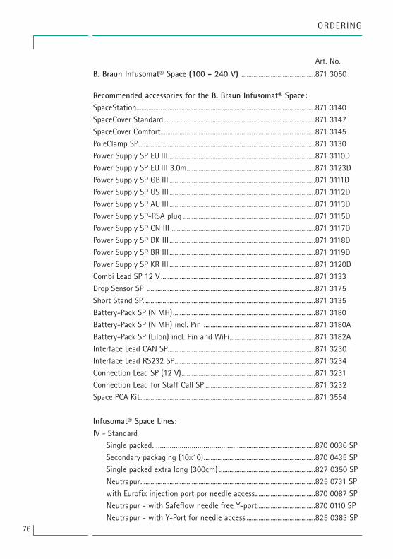
76
ORDERING
Art. No.
B. Braun Infusomat® Space (100 - 240 V) ...........................................871 3050
Recommended accessories for the B. Braun Infusomat® Space:SpaceStation............... .........................................................................................871 3140SpaceCover Standard............... .........................................................................871 3147SpaceCover Comfort..........................................................................................871 3145PoleClamp SP.......................................................................................................871 3130Power Supply SP EU III......................................................................................871 3110DPower Supply SP EU III 3.0m...........................................................................871 3123DPower Supply SP GB III .....................................................................................871 3111DPower Supply SP US III .....................................................................................871 3112DPower Supply SP AU III .....................................................................................871 3113DPower Supply SP-RSA plug .............................................................................871 3115DPower Supply SP CN III ..... ..............................................................................871 3117DPower Supply SP DK III .....................................................................................871 3118DPower Supply SP BR III .....................................................................................871 3119DPower Supply SP KR III .....................................................................................871 3120DCombi Lead SP 12 V ..........................................................................................871 3133Drop Sensor SP ..................................................................................................871 3175Short Stand SP. ...................................................................................................871 3135 Battery-Pack SP (NiMH)...................................................................................871 3180Battery-Pack SP (NiMH) incl. Pin .................................................................871 3180ABattery-Pack SP (LiIon) incl. Pin and WiFi..................................................871 3182AInterface Lead CAN SP......................................................................................871 3230Interface Lead RS232 SP..................................................................................871 3234Connection Lead SP (12 V)..............................................................................871 3231Connection Lead for Staff Call SP ................................................................871 3232Space PCA Kit......................................................................................................871 3554
Infusomat® Space Lines:IV - Standard Single packed………………………………………...........................................870 0036 SP Secondary packaging (10x10).................................................................870 0435 SP Single packed extra long (300cm) ........................................................827 0350 SP Neutrapur......................................................................................................825 0731 SP with Eurofix injection port por needle access...................................870 0087 SP Neutrapur - with Safeflow needle free Y-port..................................870 0110 SP Neutrapur - with Y-Port for needle access ........................................825 0383 SP

77
ORDERING
SafeSet IV - Standard: Single packed .............................................................................................870 1148 SP Single packed extra long (300cm) ........................................................827 0358 SP Neutrapur......................................................................................................870 1149 SP Neutrapur - with Safeflow needle free Y-port..................................870 0118 SP
UV light protected: Amber - light protected, orange tubing..............................................870 0127 SP SafeSet, amber - light protected, orange tubing .............................870 0128 SP Amber - light protected, needle free Y-Port, orange tubing ..............................................................................................825 0437 SP SafeSet, amber - light protected, needle free Y-Port, orange tubing ..............................................................................................825 0438 SP Opaque - light protected, black tubing...............................................870 0125 SP
Transfusion: with 200 µm blood filter .........................................................................827 0066 SP with 200µm blood filter, needle free Y-port......................................827 0074 SP
Enteral Nutrition: with 1000 ml Nutrifix bag, Y-port Luer Lock ....................................825 0839 SP with 1000 ml Nutrifix bag, inverse Safety Y-Port, EN Lock pat. connector ..............................................................825 0836 SP Neutrapur - with multi bottle connector ...........................................825 0857 SP Neutrapur - with multi bottle connector inverse Safety Y-Port, EN Lock pat. connector..................................825 0856 SP
Neonate: Dosifix® - 150 ml burette, Neutrapur® with needle free Safeflow Y-Port ....................................................................825 0245 SP Dosifix® - 150 ml burette, DEHP-Free tubing with Y-Port for needle access...................................................825 0294 SP

Oncology Neutrapur® - with inline 0.2 �m Sterifix® Filter ............................... 870 0095 SP SafeSet Neutrapur® - with inline 0.2 �m Sterifix® Filter ............... 870 0098 SP
Piggyback with needle free Safeflow injection port and integrated BCV..... 825 0710 SP SafeSet with needle free Safeflow injection port and integrated BCV ..........................................................................825 0718 SP secondary line with integrated BCV .....................................................406 2877 SafeSet secondary line with integrated BCV .....................................406 2878
ORDERING
78


38911794 • Drawing No. I0686700201 Printed on pulp bleached 100 % chlorine-free0715
B. Braun Melsungen AGSparte Hospital Care34209 MelsungenGermany
Tel.: +49 (0) 56 61 71-0Fax: +49 (0) 56 61 71-20 44
www.bbraun.com
Manufactured byB. Braun Melsungen AG34209 MelsungenGermanyTel +49 (0) 56 61 71-0