3d laser pulse shaping for the cornell erl photoinjector
TRANSCRIPT

3D Laser Pulse Shaping for the
Cornell ERL Photoinjector
August 9th, 2012
Sierra Cook
Advisors: Adam Bartnik,
Ivan Bazarov, Jared Maxson

Main Linac
Dump Injector
5 GeV
500m
X-rays
Accelerating Bunch
Decelerating Bunch
Energy Recovery Linac (ERL)
August 9th, 2012 3D Laser Pulse Shaping for the Cornell ERL Photoinjector 2
• Synchrotron radiation x-ray source
• Energy recovered from decelerated electron bunches
• Beam quality is set by source http://webbuild.knu.ac.kr/~accelerator/BPM.htm

ERL Photoinjector
August 9th, 2012 3D Laser Pulse Shaping for the Cornell ERL Photoinjector 3
• Provides high energy, low emittance electron bunches to the accelerator
• Beam quality is set by the source
Deflector
Experimental Beam Lines
Beam Dump
Cryomodule
Buncher
Photocathode
DC Gun
http://srf2009.bessy.de/talks/moobau04_talk.pdf
ERL Electron Gun
August 9th, 2012 3D Laser Pulse Shaping for the Cornell ERL Photoinjector 4
http://erl.chess.cornell.edu/papers/2008/First Tests of the Cornell University ERL Injector,.pdf
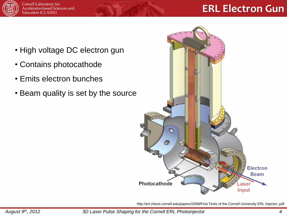
• High voltage DC electron gun
• Contains photocathode
• Emits electron bunches
• Beam quality is set by the source
Project Overview
August 9th, 2012 3D Laser Pulse Shaping for the Cornell ERL Photoinjector 5
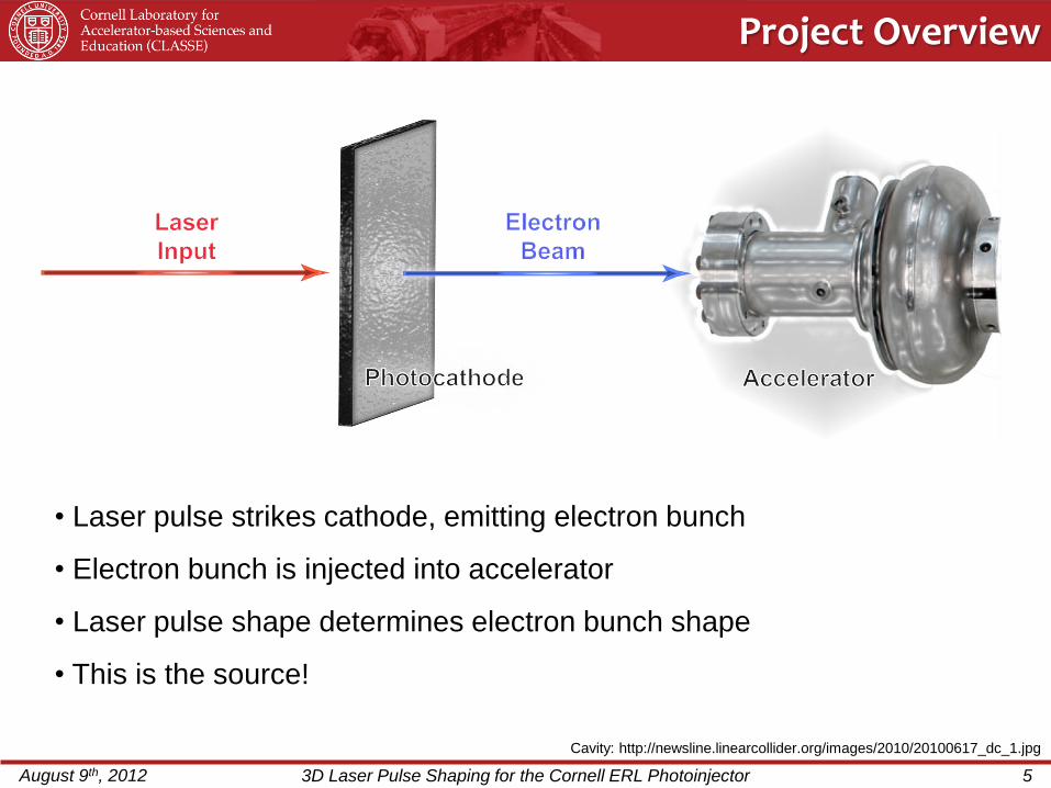
• Laser pulse strikes cathode, emitting electron bunch
• Electron bunch is injected into accelerator
• Laser pulse shape determines electron bunch shape
• This is the source!
Cavity: http://newsline.linearcollider.org/images/2010/20100617_dc_1.jpg

Project Goals (1): Clean Up Laser Pulse
August 9th, 2012 3D Laser Pulse Shaping for the Cornell ERL Photoinjector 6
Middle: http://dayton.hq.nasa.gov/IMAGES/LARGE/GPN-2002-000064.jpg
Ends: http://www.techshout.com/science/2007/05/sharpest-ever-space-images-captured-with-the-lucky-camera/
Be
fore
A
fte
r
Clean Up Beam • Remove aberrations from wavefront
Project Goal:

http://www.spring8.or.jp/en/facilities/accelerators/upgrading/project/rf_gun/fig_e/laser_shaping.jpg
Project Goals (2): Shape laser pulse
August 9th, 2012 3D Laser Pulse Shaping for the Cornell ERL Photoinjector 7
• A beam of arbitrary shape can be created by adding an appropriate phase
and passing the beam through a Fourier transforming lens
• Example: A flat-top is produced by adding a phase to the original waveform
→
Shape Beam • Produce beam of arbitrary shape
Project Goal:

Fourier Optics
August 9th, 2012 3D Laser Pulse Shaping for the Cornell ERL Photoinjector 8
• Geometric optics describes beam size
• Fourier optics describe phase propagation
• Considers waves in the spatial frequency domain
• A lens is a Fourier transformer
𝐸0 𝑥, 𝑦 𝑒−𝑖𝑘𝑧0 𝐸′ 𝑥, 𝑦 𝑒−𝑖𝑘𝑧
𝑒𝑖𝑘(𝑥2+𝑦2)/2𝑓

http://upload.wikimedia.org/wikipedia/commons/thumb/3/3d/Zernike_polynomials2.png/360px-Zernike_polynomials2.png
Optical Aberrations (1)
August 9th, 2012 3D Laser Pulse Shaping for the Cornell ERL Photoinjector 9
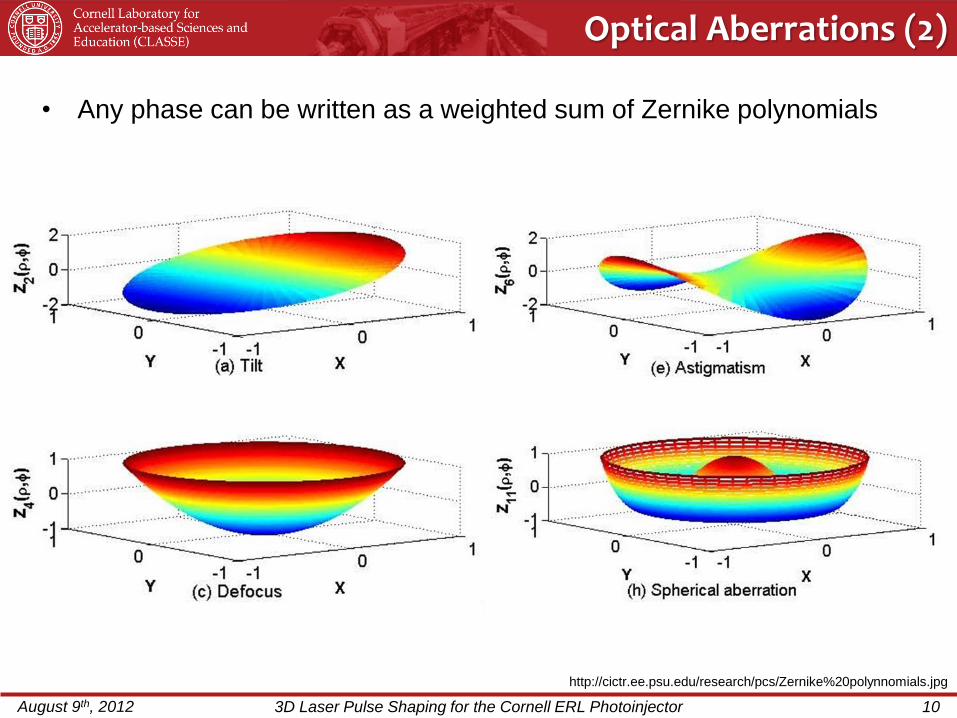
Example • Zernike Polynomials are used to describe optical aberrations
• Orthogonal set of polynomials used in optics
𝑍𝑚𝑛(𝜌, 𝜑) = 𝑅𝑚𝑛 𝜌 𝐶𝑜𝑠(𝑚𝜑)
𝑍𝑚𝑛 𝜌, 𝜑 = −𝑅𝑚𝑛 𝜌 𝑆𝑖𝑛(𝑚𝜑)
http://cictr.ee.psu.edu/research/pcs/Zernike%20polynnomials.jpg
Optical Aberrations (2)
August 9th, 2012 3D Laser Pulse Shaping for the Cornell ERL Photoinjector 10
Example • Any phase can be written as a weighted sum of Zernike polynomials

http://www.sciencedirect.com/science/article/pii/S0168900205006686
Laser Shaping (1)
August 9th, 2012 3D Laser Pulse Shaping for the Cornell ERL Photoinjector 11
Example
Shack Hartman Apparatus - Measures the phase of the wavefront
• Non-flat wavefronts produce shifted spot patterns on the sensor
• Reconstructs wavefront by analyzing how much each point is shifted

Micromachined Membrane Deformable Mirror (MMDM)
- Shapes the wavefront
August 9th, 2012 3D Laser Pulse Shaping for the Cornell ERL Photoinjector 12
Image of MMDM
MMDM Schematic
• Mirror changes phase of incoming laser beam
• Applying voltage to actuators deforms mirror membrane
• Shape of added phase corresponds to shape of mirror
Left: http://www.okotech.com/15-mm-37-ch-qoko-mirrorq
Right: http://www.okotech.com/images/pdfs/catwww3.pdf
MMDM

Laser Shaping (2)
August 9th, 2012 3D Laser Pulse Shaping for the Cornell ERL Photoinjector 13
Example
• Mirror shape corresponds to phase shape
Incoming Plane Wave
Mirror
Reflected Wave
Mirror

Example: Shaping the Laser Pulse
August 9th, 2012 3D Laser Pulse Shaping for the Cornell ERL Photoinjector 14
Example • MMDM can be used to change the intensity of the beam
– Add phase with MMDM
– Use lens to Fourier transform beam
+ Phase
+ Fourier Transform
Gaussian Beam Flat-Top Beam
Frontsurfer Software (1)
August 9th, 2012 3D Laser Pulse Shaping for the Cornell ERL Photoinjector 15
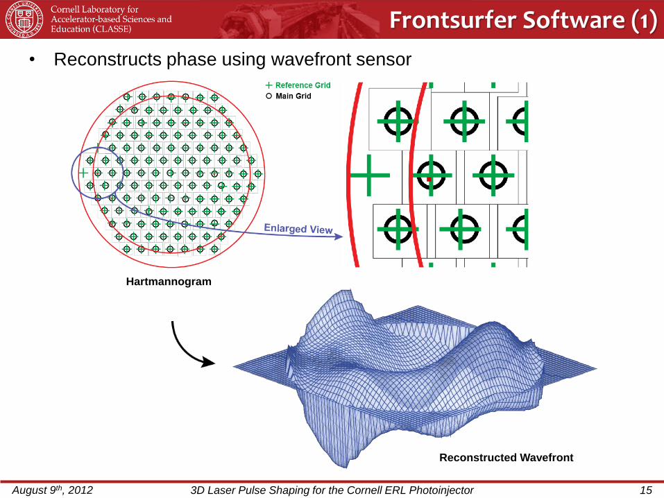
Example • Reconstructs phase using wavefront sensor
Hartmannogram
Reconstructed Wavefront

Frontsurfer Software (2)
August 9th, 2012 3D Laser Pulse Shaping for the Cornell ERL Photoinjector 16
Example
• Adjusts MMDM actuator voltages to produce target function
Initial Shape
Target Function
Zero Actuator Voltage
Astigmatism

http://www.okotech.com/images/okoimages/fs_screen1big.jpg
Frontsurfer Software (3)
August 9th, 2012 3D Laser Pulse Shaping for the Cornell ERL Photoinjector 18
Example
• Frontsurfer software interface
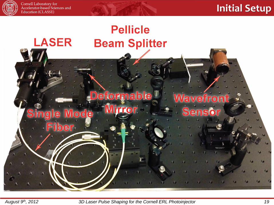
Initial Setup
August 9th, 2012 3D Laser Pulse Shaping for the Cornell ERL Photoinjector 19

Target Function: Flat Phase
Peak−to−valley = 0.258 waves
Initial Results
August 9th, 2012 3D Laser Pulse Shaping for the Cornell ERL Photoinjector 20
Initial Shape
Peak-to-valley = 1.158 Waves
• Flattens wave, but not well ‒ Peak-to-Valley distance decreased by 80%

August 9th, 2012 3D Laser Pulse Shaping for the Cornell ERL Photoinjector 21
Resize Beam
• Problem: Wrong Size Beam
– Too few active Zernike modes
– Beam covers insufficient mirror area
– Unable to use all actuators effectively
• Solution: Resize Beam
– Expand beam to cover more mirror surface
– Resize beam at wavefront sensor

August 9th, 2012 3D Laser Pulse Shaping for the Cornell ERL Photoinjector 22
Initial Shape
Peak-to-valley = 5.502 Waves
Target Function: Flat Phase
Peak−to−valley = 0.087 waves
Beam Successfully Flattened
Clean Up Beam • Remove aberrations from wavefront
Goal Complete:
• Successfully flattens wave ‒ Peak-to-valley distance decreased by 98.5%

Turning a Gaussian into a Flat-Top (1)
August 9th, 2012 3D Laser Pulse Shaping for the Cornell ERL Photoinjector 23
1. Calculate phase needed to change intensity distribution
𝜑 𝜉 =𝐷𝑘02𝑓 1 − 𝑒−𝑠
2𝑑𝑠
𝜉
0
2. Write phase in terms of a weighted sum of Zernike polynomial
𝜑 = 𝐴𝑚𝑛𝑍𝑚𝑛
𝐴𝑚𝑛 =< 𝜑 | 𝑍𝑚𝑛 >
3. Input Zernike coefficients into Frontsurfer software
Shape Beam • Produce beam of arbitrary shape
Next Goal:
Process:
𝐷 = 𝐼𝑛𝑖𝑡𝑖𝑎𝑙 𝑆𝑖𝑧𝑒
𝑘0 =2𝜋
𝜆
𝑓 = 𝑓𝑜𝑐𝑎𝑙 𝑙𝑒𝑛𝑔𝑡ℎ
s =r
w
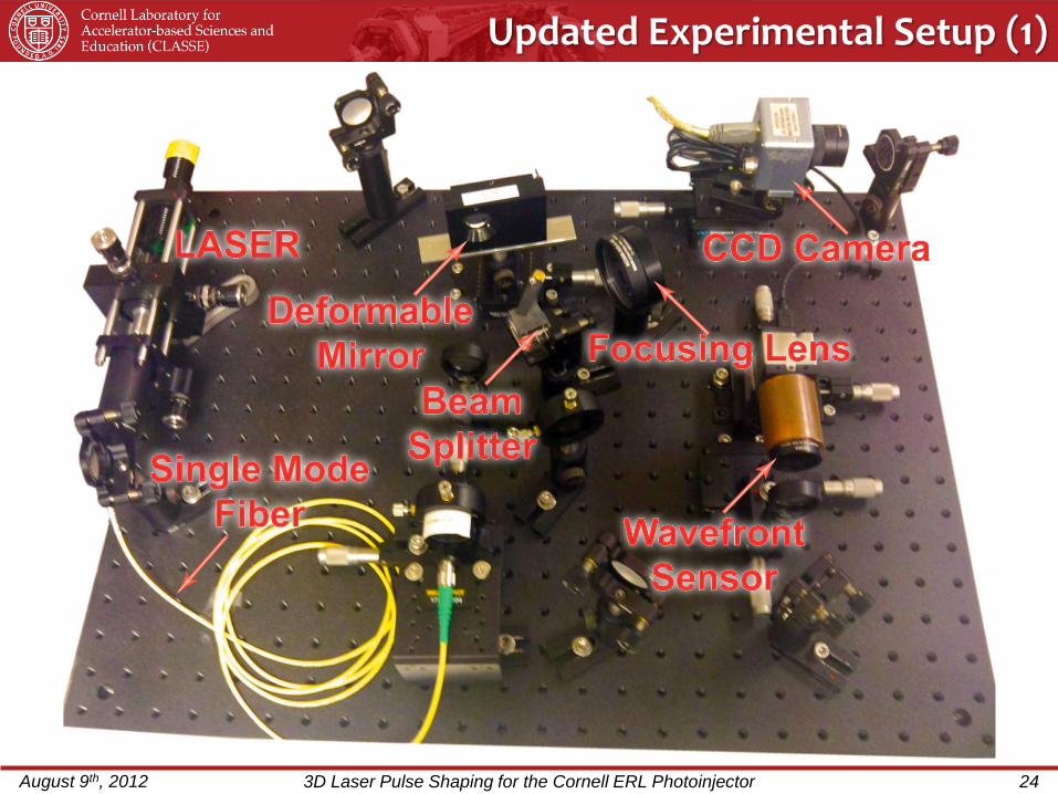
Updated Experimental Setup (1)
August 9th, 2012 3D Laser Pulse Shaping for the Cornell ERL Photoinjector 24
Example

Updated Experimental Setup (2)
August 9th, 2012 3D Laser Pulse Shaping for the Cornell ERL Photoinjector 25
Example

Turning a Gaussian into a Flat-Top (2)
August 9th, 2012 3D Laser Pulse Shaping for the Cornell ERL Photoinjector 26
Matlab Results Our Results
Bright Fringes
Hexagonal Shape
Uniform Intensity
Circular Shape

Wrong initial beam size?
August 9th, 2012 3D Laser Pulse Shaping for the Cornell ERL Photoinjector 27
Our Results
7.9mm Beam
Matlab Results
Actual beam
10% larger than beam
used to calculate phase
Matlab Results
Actual beam
10% smaller than beam
used to calculate phase

August 9th, 2012 3D Laser Pulse Shaping for the Cornell ERL Photoinjector 28
Reduced Beam Diameter to 5mm
Before After
Before After
Resize
Improvements:
• No Hexagonal Shape
• Bright Fringe Reduced
Shortcomings:
• Not a Flat-Top
• Unable to Produce Target Functions
• Too few active Zernike modes

Improvements:
• Able to roughly generate target
functions
• More active Zernike modes
• More circular shape than 7.9mm beam
August 9th, 2012 3D Laser Pulse Shaping for the Cornell ERL Photoinjector 29
Resize Beam Diameter to 5.75 mm
After
Resize
Shortcomings:
• Not a Flat-Top
• Larger Bright Fringe than 5mm Beam
Before

• Problem:
– Actuator voltages are maxed out
• Cause:
– Amplitude of Zernike coefficients are too high
• Next step:
– Make added phase smaller
𝜑 𝜉 =𝐷𝑘02𝑓 1 − 𝑒−𝑠
2𝑑𝑠
𝜉
0
𝑠 =𝑟
𝑤, 𝑤 = initial beam size
August 9th, 2012 3D Laser Pulse Shaping for the Cornell ERL Photoinjector 31
Reducing Phase (1)

• Reduce size of added phase:
𝜑 𝜉 =𝐷𝑘0
2𝑓 1 − 𝑒−𝑠
2𝑑𝑠
𝜉
0
𝑠 = 𝑟
𝑤, 𝑤 = 𝐵𝑒𝑎𝑚 𝑤𝑖𝑑𝑡ℎ
August 9th, 2012 3D Laser Pulse Shaping for the Cornell ERL Photoinjector 32
0 2 4 6 8 100
2
4
6
8
10
r/w
Reducing Phase (2)
• Increasing w decreases 𝜑
– Even with maximum allowable value of
w, Zernike coefficients are too large
• Increasing focal length of focusing
lens decreases 𝜑
Ph
ase
1x Beam Width
2x Beam Width
3x Beam Width
4x Beam Width
0.0 0.2 0.4 0.6 0.8 1.00.0
0.1
0.2
0.3
0.4
0.5 Phase vs. r/w
Conclusions
August 9th, 2012 3D Laser Pulse Shaping for the Cornell ERL Photoinjector 34
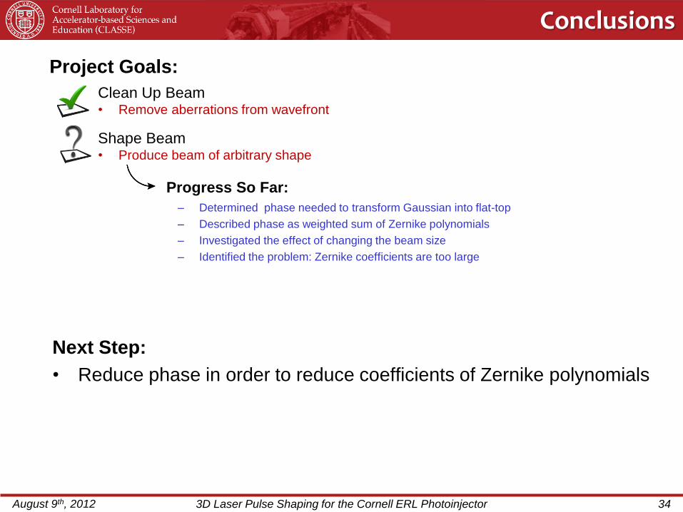
Next Step:
• Reduce phase in order to reduce coefficients of Zernike polynomials
– Determined phase needed to transform Gaussian into flat-top
– Described phase as weighted sum of Zernike polynomials
– Investigated the effect of changing the beam size
– Identified the problem: Zernike coefficients are too large
Progress So Far:
Clean Up Beam • Remove aberrations from wavefront
Project Goals:
Shape Beam • Produce beam of arbitrary shape
1. Adaptive Optic Systems. OKOtech Flexible Optical.
6/15/2012.<http://www.okotech. com/ao-systems>
2. Adaptive Optics Guide. OKO Flexible Optical; April 2008
Edition.
3. Dickey, Fred, Holswade, Scott. Laser Beam Shaping:
Theory and Techniques. Copyright 2000, Marcel
Decker, inc.
4. Wavefront Sensors. OKOtech Flexible Optical. 6/15/2012.
<http://www.okotech. com/sensors>
5. Wavefront sensors: Shack-Hartmann.
<http://www.ctio.noao..edu/~atokovin/tut
orial/part3/wfs.html>
August 9th, 2012 3D Laser Pulse Shaping for the Cornell ERL Photoinjector 35
References