3d measuring and marking-out machines · 3d measuring and marking-out machines ... • high working...
TRANSCRIPT
FRATELLIROTONDI
3D measuringand marking-out machines
®
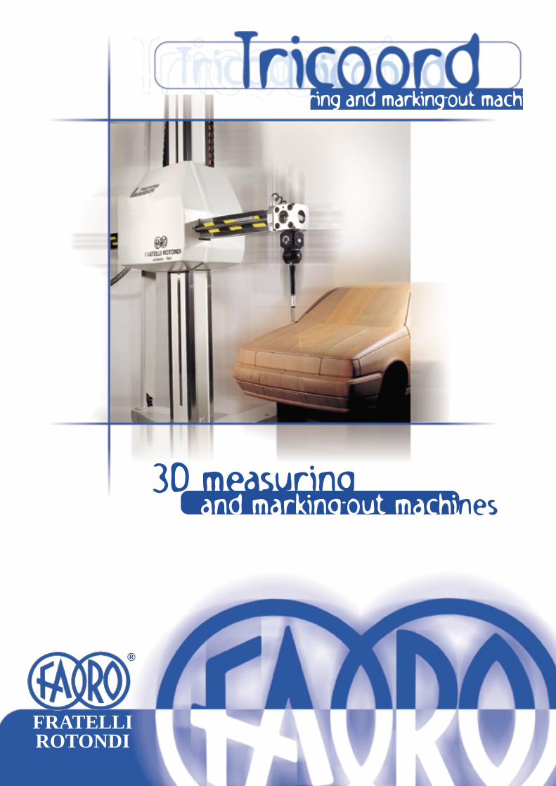
3D measuring and marking-out machines
3D measuring and marking-out machine - open structure on all the sides and horizontal axis type - high per-formance standards.
Versions:
- automatic
- manual
Different and custom-made models permit to face any requirement and therefore this kind of machine may besuitably utilized in various fields of the dimensional control. The working range concerns the small, middle andlarge sizes.
This machine is the outcome of a tradition in metrology lasting more than fifty years and an experience of thirtyyears in the manufacturing of this type of units.
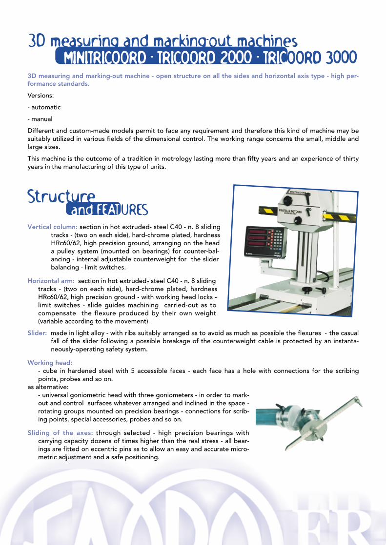
Vertical column: section in hot extruded- steel C40 - n. 8 slidingtracks - (two on each side), hard-chrome plated, hardnessHRc60/62, high precision ground, arranging on the heada pulley system (mounted on bearings) for counter-bal-ancing - internal adjustable counterweight for the sliderbalancing - limit switches.
Horizontal arm: section in hot extruded- steel C40 - n. 8 sliding tracks - (two on each side), hard-chrome plated, hardnessHRc60/62, high precision ground - with working head locks -limit switches - slide guides machining carried-out as tocompensate the flexure produced by their own weight(variable according to the movement).
Slider: made in light alloy - with ribs suitably arranged as to avoid as much as possible the flexures - the casualfall of the slider following a possible breakage of the counterweight cable is protected by an instanta-neously-operating safety system.
Working head:- cube in hardened steel with 5 accessible faces - each face has a hole with connections for the scribingpoints, probes and so on.
as alternative:- universal goniometric head with three goniometers - in order to mark-out and control surfaces whatever arranged and inclined in the space -rotating groups mounted on precision bearings - connections for scrib-ing points, special accessories, probes and so on.
Sliding of the axes: through selected - high precision bearings withcarrying capacity dozens of times higher than the real stress - all bear-ings are fitted on eccentric pins as to allow an easy and accurate micro-metric adjustment and a safe positioning.
3D measuring and marking-out machinesMMIINNIITTRRIICCOOOORRDD -- TTRRIICCOOOORRDD 22000000 -- TTRRIICCOOOORRDD 33000000
Structureand FEATURES
3D measuring and marking-out mDriving of the axes: through pinion and rack on all the axes (manual version) - through pinion and rack and
special smooth bar systems (automatic version).
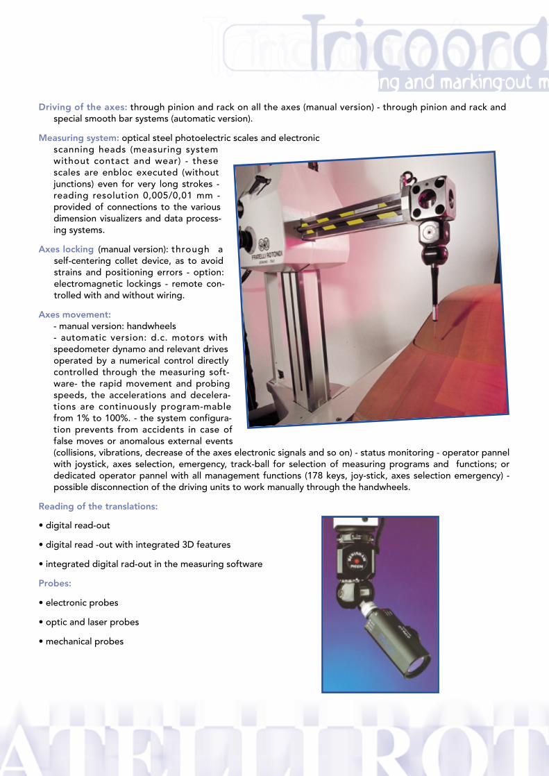
Measuring system: optical steel photoelectric scales and electronic scanning heads (measuring systemwithout contact and wear) - thesescales are enbloc executed (withoutjunctions) even for very long strokes -reading resolution 0,005/0,01 mm -provided of connections to the variousdimension visualizers and data process-ing systems.
Axes locking (manual version): through aself-centering collet device, as to avoidstrains and positioning errors - option:electromagnetic lockings - remote con-trolled with and without wiring.
Axes movement:- manual version: handwheels- automatic version: d.c. motors withspeedometer dynamo and relevant drivesoperated by a numerical control directlycontrolled through the measuring soft-ware- the rapid movement and probingspeeds, the accelerations and decelera-tions are continuously program-mablefrom 1% to 100%. - the system configura-tion prevents from accidents in case offalse moves or anomalous external events(collisions, vibrations, decrease of the axes electronic signals and so on) - status monitoring - operator pannelwith joystick, axes selection, emergency, track-ball for selection of measuring programs and functions; ordedicated operator pannel with all management functions (178 keys, joy-stick, axes selection emergency) -possible disconnection of the driving units to work manually through the handwheels.
Reading of the translations:
• digital read-out
• digital read -out with integrated 3D features
• integrated digital rad-out in the measuring software
Probes:
• electronic probes
• optic and laser probes
• mechanical probes
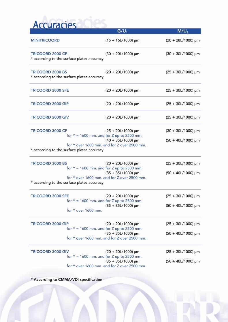
AccuraciesG/U1 M/U3
MINITRICOORD (15 + 16L/1000) µm (20 + 28L/1000) µm
TRICOORD 2000 CP (30 + 20L/1000) µm (30 + 30L/1000) µm* according to the surface plates accuracy
TRICOORD 2000 BS (20 + 20L/1000) µm (25 + 30L/1000) µm* according to the surface plates accuracy
TRICOORD 2000 SFE (20 + 20L/1000) µm (25 + 30L/1000) µm
TRICOORD 2000 GIP (20 + 20L/1000) µm (25 + 30L/1000) µm
TRICOORD 2000 GIV (20 + 20L/1000) µm (25 + 30L/1000) µm
TRICOORD 3000 CP (25 + 20L/1000) µm (30 + 30L/1000) µmfor Y = 1600 mm. and for Z up to 2500 mm.
(40 + 35L/1000) µm (50 + 40L/1000) µmfor Y over 1600 mm. and for Z over 2500 mm.
* according to the surface plates accuracy
TRICOORD 3000 BS (20 + 20L/1000) µm (25 + 30L/1000) µmfor Y = 1600 mm. and for Z up to 2500 mm.
(35 + 35L/1000) µm (50 + 40L/1000) µmfor Y over 1600 mm. and for Z over 2500 mm.
* according to the surface plates accuracy
TRICOORD 3000 SFE (20 + 20L/1000) µm (25 + 30L/1000) µmfor Y = 1600 mm. and for Z up to 2500 mm.
(35 + 35L/1000) µm (50 + 40L/1000) µmfor Y over 1600 mm.
TRICOORD 3000 GIP (20 + 20L/1000) µm (25 + 30L/1000) µmfor Y = 1600 mm. and for Z up to 2500 mm.
(35 + 35L/1000) µm (50 + 40L/1000) µmfor Y over 1600 mm. and for Z over 2500 mm.
TRICOORD 3000 GIV (20 + 20L/1000) µm (25 + 30L/1000) µmfor Y = 1600 mm. and for Z up to 2500 mm.
(35 + 35L/1000) µm (50 + 40L/1000) µmfor Y over 1600 mm. and for Z over 2500 mm.
* According to CMMA/VDI specification
Accuracies
3D measuring and marking-out m
Measuring SOFTWARE
The various models of the machine TRICOORD differ because of their structure:
MINITRICOORD - section of the vertical column mm. 100 x 100- section of the horizontal arm mm. 50 x 40
TRICOORD 2000 - section of the vertical column mm.140 x 120- section of the horizontal arm mm. 70 x 50
TRICOORD 3000 - section of the vertical column mm. 192 x 168- section of the horizontal arm mm. 90 x 60
The versions of the machine TRICOORD differ because of their type ofsliding along the longitudinal axis.
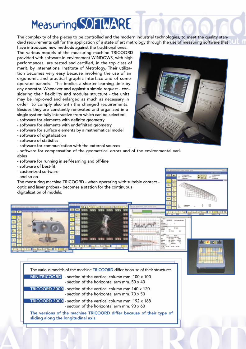
The complexity of the pieces to be controlled and the modern industrial technologies, to meet the quality stan-dard requirements call for the application of a state of art metrology through the use of measuring software thathave introduced new methods against the traditional ones.The various models of the measuring machine TRICOORDprovided with software in environment WINDOWS, with highperformances are tested and certified, in the top class ofmerit, by International Institute of Metrology. Their utiliza-tion becomes very easy because involving the use of anergonomic and practical graphic interface and of someoperator pannels. This implies a shorter learning time byany operator. Whenever and against a simple request - con-sidering their flexibility and modular structure - the unitsmay be improved and enlarged as much as necessary inorder to comply also with the changed requirements.Besides they are constantly renovated and organized in asingle system fully interactive from which can be selected:- software for elements with definite geometry- software for elements with undefinited geometry- software for surface elements by a mathematical model- software of digitalization- software of statistics- software for communication with the external sources- software for compensation of the geometrical errors and of the environmental vari-ables- software for running in self-learning and off-line- software of best-fit- customized software- and so onThe measuring machine TRICOORD - when operating with suitable contact - optic and laser probes - becomes a station for the continuous digitalization of models.
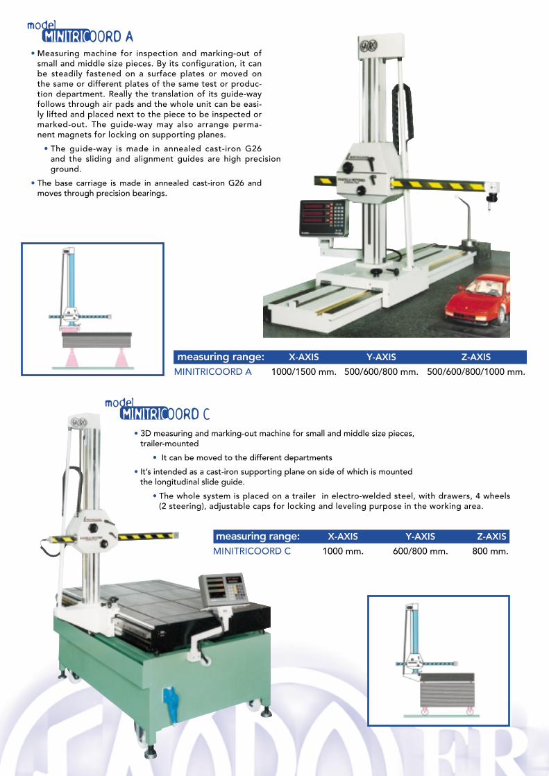
• Measuring machine for inspection and marking-out ofsmall and middle size pieces. By its configuration, it canbe steadily fastened on a surface plates or moved onthe same or different plates of the same test or produc-tion department. Really the translation of its guide-wayfollows through air pads and the whole unit can be easi-ly lifted and placed next to the piece to be inspected ormarked-out. The guide-way may also arrange perma-nent magnets for locking on supporting planes.
• The guide-way is made in annealed cast-iron G26and the sliding and alignment guides are high precisionground.
• The base carriage is made in annealed cast-iron G26 andmoves through precision bearings.
measuring range: X-AXIS Y-AXIS Z-AXIS
MINITRICOORD A 1000/1500 mm. 500/600/800 mm. 500/600/800/1000 mm.
• 3D measuring and marking-out machine for small and middle size pieces,trailer-mounted
• It can be moved to the different departments
• It’s intended as a cast-iron supporting plane on side of which is mountedthe longitudinal slide guide.
• The whole system is placed on a trailer in electro-welded steel, with drawers, 4 wheels(2 steering), adjustable caps for locking and leveling purpose in the working area.
measuring range: X-AXIS Y-AXIS Z-AXIS
MINITRICOORD C 1000 mm. 600/800 mm. 800 mm.
modelMINITRICOORD A
modelMINITRICOORD C
3D measuring and marking-out m
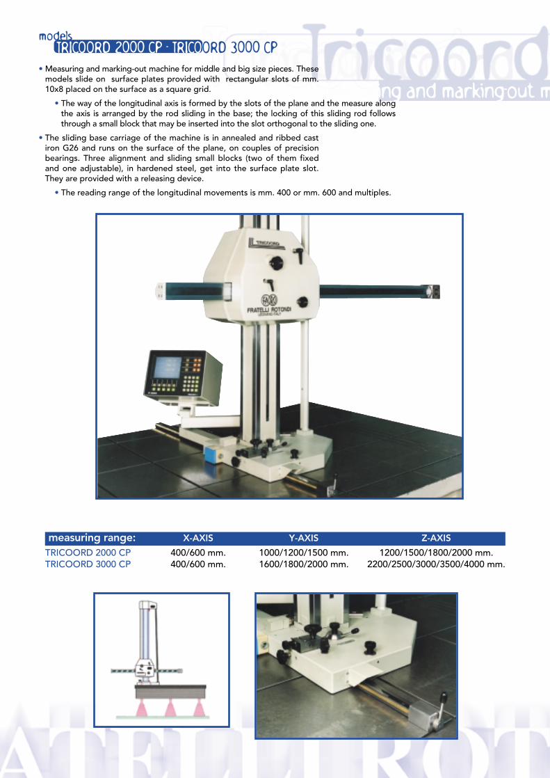
measuring range: X-AXIS Y-AXIS Z-AXIS
TRICOORD 2000 CP 400/600 mm. 1000/1200/1500 mm. 1200/1500/1800/2000 mm.TRICOORD 3000 CP 400/600 mm. 1600/1800/2000 mm. 2200/2500/3000/3500/4000 mm.
modelsTRICOORD 2000 CP - TRICOORD 3000 CP
• Measuring and marking-out machine for middle and big size pieces. Thesemodels slide on surface plates provided with rectangular slots of mm.10x8 placed on the surface as a square grid.
• The way of the longitudinal axis is formed by the slots of the plane and the measure alongthe axis is arranged by the rod sliding in the base; the locking of this sliding rod followsthrough a small block that may be inserted into the slot orthogonal to the sliding one.
• The sliding base carriage of the machine is in annealed and ribbed castiron G26 and runs on the surface of the plane, on couples of precisionbearings. Three alignment and sliding small blocks (two of them fixedand one adjustable), in hardened steel, get into the surface plate slot.They are provided with a releasing device.
• The reading range of the longitudinal movements is mm. 400 or mm. 600 and multiples.
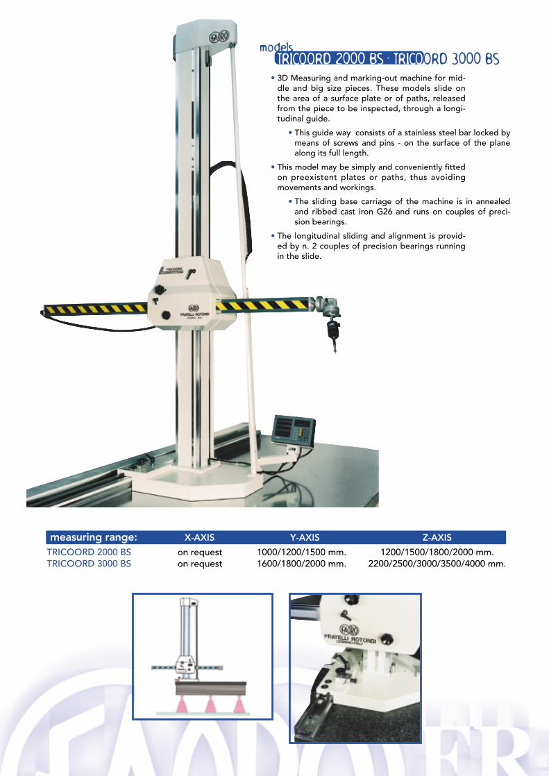
• 3D Measuring and marking-out machine for mid-dle and big size pieces. These models slide onthe area of a surface plate or of paths, releasedfrom the piece to be inspected, through a longi-tudinal guide.
• This guide way consists of a stainless steel bar locked bymeans of screws and pins - on the surface of the planealong its full length.
• This model may be simply and conveniently fittedon preexistent plates or paths, thus avoidingmovements and workings.
• The sliding base carriage of the machine is in annealedand ribbed cast iron G26 and runs on couples of preci-sion bearings.
• The longitudinal sliding and alignment is provid-ed by n. 2 couples of precision bearings runningin the slide.
measuring range: X-AXIS Y-AXIS Z-AXIS
TRICOORD 2000 BS on request 1000/1200/1500 mm. 1200/1500/1800/2000 mm.TRICOORD 3000 BS on request 1600/1800/2000 mm. 2200/2500/3000/3500/4000 mm.
modelsTRICOORD 2000 BS - TRICOORD 3000 BS
3D measuring and marking-out m
measuring range: X-AXIS Y-AXIS Z-AXIS
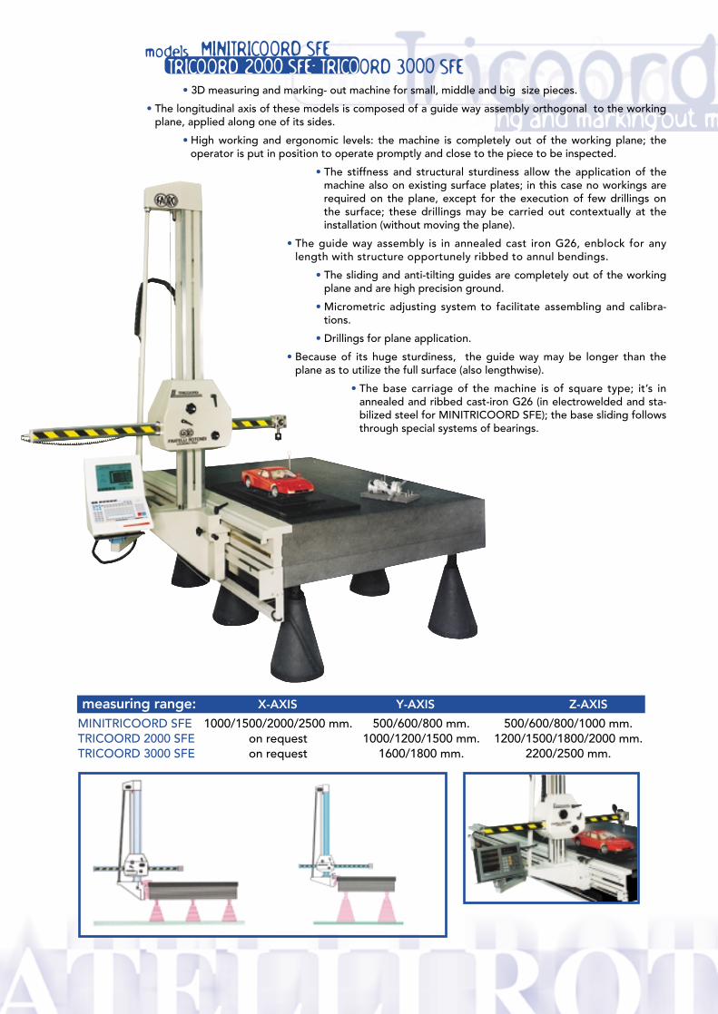
MINITRICOORD SFE 1000/1500/2000/2500 mm. 500/600/800 mm. 500/600/800/1000 mm.TRICOORD 2000 SFE on request 1000/1200/1500 mm. 1200/1500/1800/2000 mm.TRICOORD 3000 SFE on request 1600/1800 mm. 2200/2500 mm.
modelsTRICOORD 2000 SFE- TRICOORD 3000 SFE
MINITRICOORD SFE
• 3D measuring and marking- out machine for small, middle and big size pieces.
• The longitudinal axis of these models is composed of a guide way assembly orthogonal to the workingplane, applied along one of its sides.
• High working and ergonomic levels: the machine is completely out of the working plane; theoperator is put in position to operate promptly and close to the piece to be inspected.
• The stiffness and structural sturdiness allow the application of themachine also on existing surface plates; in this case no workings arerequired on the plane, except for the execution of few drillings onthe surface; these drillings may be carried out contextually at theinstallation (without moving the plane).
• The guide way assembly is in annealed cast iron G26, enblock for anylength with structure opportunely ribbed to annul bendings.
• The sliding and anti-tilting guides are completely out of the workingplane and are high precision ground.
• Micrometric adjusting system to facilitate assembling and calibra-tions.
• Drillings for plane application.
• Because of its huge sturdiness, the guide way may be longer than theplane as to utilize the full surface (also lengthwise).
• The base carriage of the machine is of square type; it’s inannealed and ribbed cast-iron G26 (in electrowelded and sta-bilized steel for MINITRICOORD SFE); the base sliding followsthrough special systems of bearings.
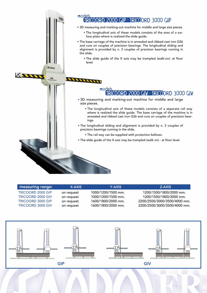
• 3D measuring and marking-out machine for middle and largesize pieces.
• The longitudinal axis of these models consists of a separate rail waywhere is realized the slide guide. The base carriage of the machine is inannealed and ribbed cast iron G26 and runs on couples of precision bear-ings.
• The longitudinal sliding and alignment is provided by n. 2 couples ofprecision bearings running in the slide.
• The rail way can be supplied with protection bellows.
• The slide guide of the X axis may be trampled (walk on) - at floor level.
• 3D measuring and marking-out machine for middle and large size pieces.
• The longitudinal axis of these models consists of the area of a sur-face plate where is realized the slide guide.
• The base carriage of the machine is in annealed and ribbed cast iron G26and runs on couples of precision bearings. The longitudinal sliding andalignment is provided by n. 2 couples of precision bearings running inthe slide.
• The slide guide of the X axis may be trampled (walk-on)- at floorlevel.
measuring range: X-AXIS Y-AXIS Z-AXIS
TRICOORD 2000 GIP on request 1000/1200/1500 mm. 1200/1500/1800/2000 mm.TRICOORD 2000 GIV on request 1000/1200/1500 mm. 1200/1500/1800/2000 mm.TRICOORD 3000 GIP on request 1600/1800/2000 mm. 2200/2500/3000/3500/4000 mm.TRICOORD 3000 GIV on request 1600/1800/2000 mm. 2200/2500/3000/3500/4000 mm.
modelsTRICOORD 2000 GIP - TRICOORD 3000 GIP
modelsTRICOORD 2000 GIV - TRICOORD 3000 GIV
GIP GIV
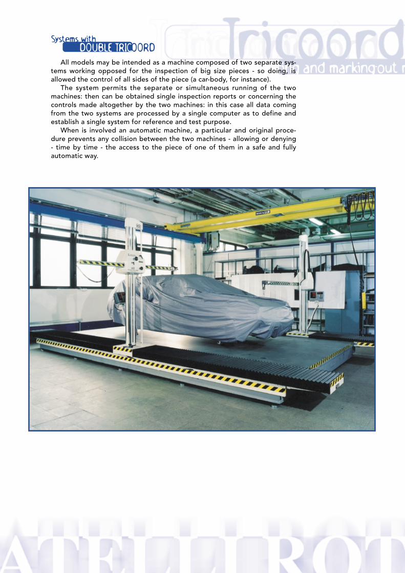
Systems withDOUBLE TRICOORD
3D measuring and marking-out mAll models may be intended as a machine composed of two separate sys-tems working opposed for the inspection of big size pieces - so doing, isallowed the control of all sides of the piece (a car-body, for instance).
The system permits the separate or simultaneous running of the twomachines: then can be obtained single inspection reports or concerning thecontrols made altogether by the two machines: in this case all data comingfrom the two systems are processed by a single computer as to define andestablish a single system for reference and test purpose.
When is involved an automatic machine, a particular and original proce-dure prevents any collision between the two machines - allowing or denying- time by time - the access to the piece of one of them in a safe and fullyautomatic way.

FRATELLIROTONDI
20025 Legnano (MI) ITALY - Via F.lli Bandiera, 36 Tel. ++39.0331.442074 - Fax ++39.0331.453863 http: //www.rotondi.it • E-mail: [email protected]
®