4 fixed point simulation - tkk tietoliikennelaboratorio fixed point simulation.pdf ·...
TRANSCRIPT

Lecture 4: Make fixed point simulation using Matlab
March 28 – April 19 2008
Yuping Zhao (Doctor of Science in technology)
Professor, Peking UniversityBeijing, China

General explanation• For the floating point simulation, normally we have• A=3; B=5; C=A+B;• Here A, B, C are the floating point data, the number of
bits to represent the data is defined in MATLAB• However, for the hardware implementation, each data
should be represented by a certain number of “0”,”1”. Therefore all the operation is also done for those binary sequences.
• In the real word, the A/D converter will make the samples of the received signals and change it to the binary data with defined length

How does the A/D converter works?
• It should define the sampling frequency, normally it is 2-6 times of the signal bandwidth
• It should define the maximum and minimum value of samples. The signal value out of the range will be truncated.
• It should define the number of bits for representing each sample. This will define the quantization accuracy

Min Max

Example 1Assume the A/D range is[-10~10],the number of bits for
each sample is 10 bit. The first bit normally represent the plus or minus value, and rest 9 bits represent the absolute value of sample.
10: -> “0111111111”-10: -> “1000000001” (using complementary data)The accuracy of quantization is(10+10)/(511+511)=0.0196,(about 0.02)Note: If the input to the A/D converter is larger than 10, the
out put will be 10. The sample is truncated.

Example 2
Assume the A/D range is[-1~1],the number of bits for each sample is 10 bit.
1: -> “0111111111”-1: -> “1000000001” (using complementary
data)The accuracy of quantization is(1+1)/(511+511)=0.00196,(about 0.002)

Example 3
Assume the A/D range is[-10~10],the number of bits for each sample is 5 bit.
1: -> “01111”-1: -> “10001” (using complementary data)The accuracy of quantization is(10+10)/(15+15)=0.6667,(about 0.7)

How to do the calculation using fixed point signals
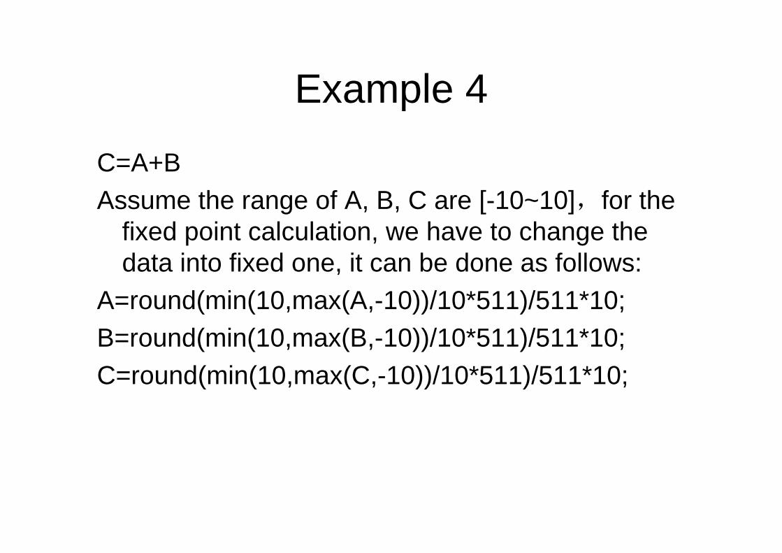
Example 4
C=A+BAssume the range of A, B, C are [-10~10],for the
fixed point calculation, we have to change the data into fixed one, it can be done as follows:
A=round(min(10,max(A,-10))/10*511)/511*10;B=round(min(10,max(B,-10))/10*511)/511*10;C=round(min(10,max(C,-10))/10*511)/511*10;

Example: convert A into Fixed point value YY = round(min(10,max(A,-10))/10*511)/511*10;
• “max(A,-10)”: to ensure the data always larger than -10• “min(10,max(A,-10))”: to ensure the data always smaller
than 10• “/10*511”: change the data into binary one• “round”” take the integer data• “/511*10” change back into decimal data
By doing so, Y becomes fixed point data, but shown in floating point valueExample: A = 9.5, Y = 9.4912
A = 13, Y = 10A = -7, Y = -7.0059

General functionC=round(min(10,max(C,-10))/10*511)/511*10
function Y = fixed(X,A,K)% X: input floating point data% A: The maximum value of the output, A>0% K: The total number bits for quantizationN = 2^(K-1) – 1;Y = round(min(A,max(X,-A))/A*N)/N*A
(In practice, normally we use “floor” rather than “round”)
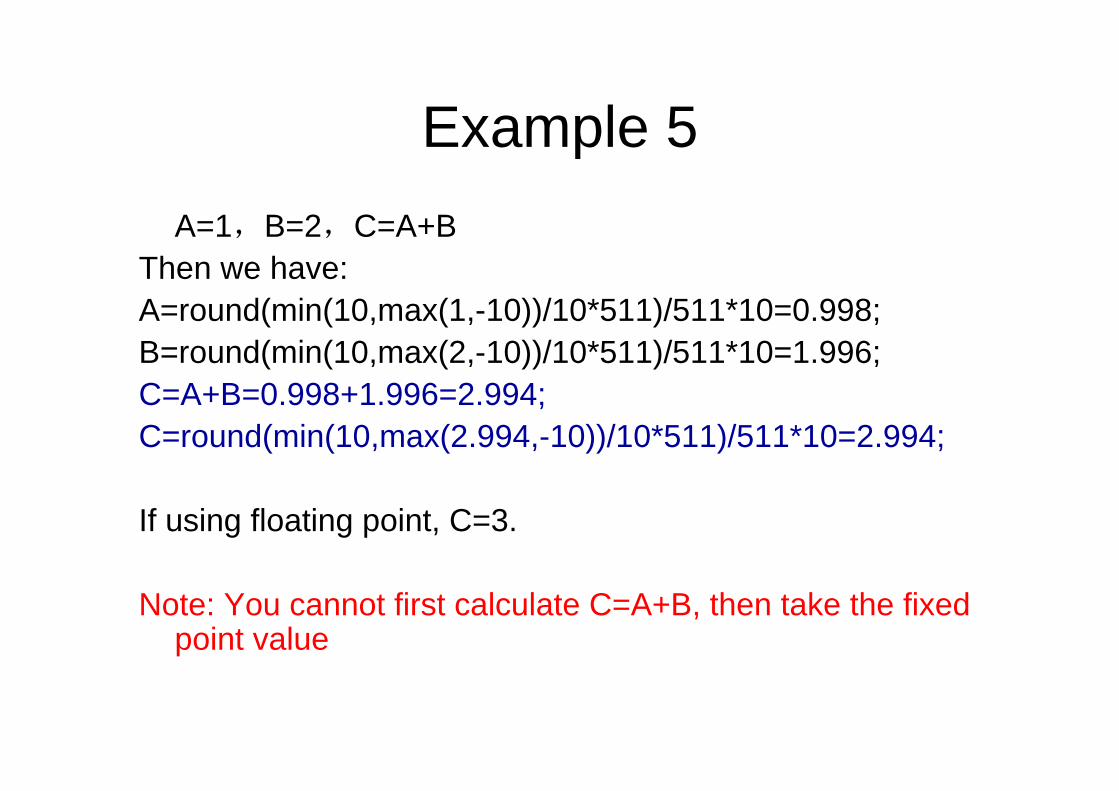
Example 5A=1,B=2,C=A+B
Then we have:A=round(min(10,max(1,-10))/10*511)/511*10=0.998;B=round(min(10,max(2,-10))/10*511)/511*10=1.996;C=A+B=0.998+1.996=2.994;C=round(min(10,max(2.994,-10))/10*511)/511*10=2.994;
If using floating point, C=3.
Note: You cannot first calculate C=A+B, then take the fixed point value
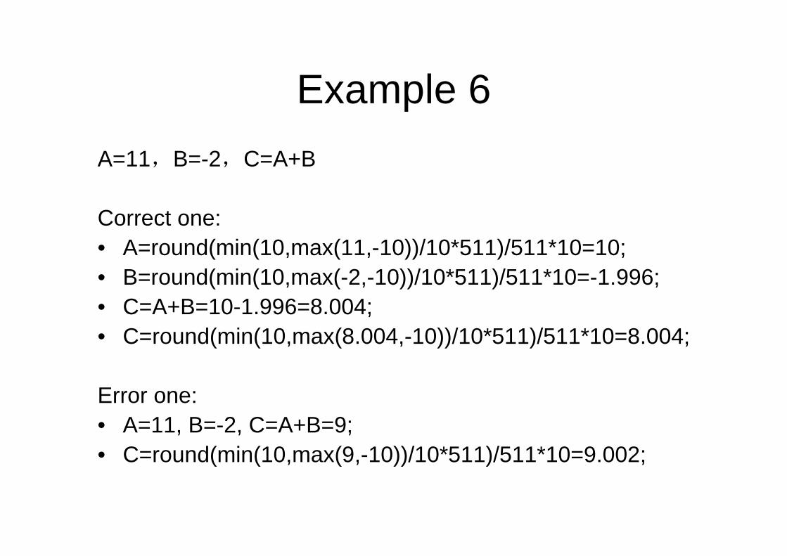
Example 6A=11,B=-2,C=A+B
Correct one:• A=round(min(10,max(11,-10))/10*511)/511*10=10;• B=round(min(10,max(-2,-10))/10*511)/511*10=-1.996;• C=A+B=10-1.996=8.004;• C=round(min(10,max(8.004,-10))/10*511)/511*10=8.004;
Error one:• A=11, B=-2, C=A+B=9;• C=round(min(10,max(9,-10))/10*511)/511*10=9.002;

Notes:
• Normally the multiplication results require more bits than the original data– Example: c=a*b; a,b—10 bits; c -- 20 bits
• For division, the accuracy of divider is very important
• Normally, small number of bits make systems simple, large number of bits make systems accurate

How to decide parameters for A/D converter
• The sampling rate for A/D converter• The A/D range• The number of bits for each data

Example: Structure of the receiverBase-band System
Amplifier A/D Frame detection
Frequency error
compensation
Frequency error
estimation
(AGC)
synchronizationLength detectio
n
demodulation CRC
Local PN sequence

• To make received signal in the suitable level– Too large:
some signals are truncated
– Too small: the resolution is not enough
AGC should be used to adjust signals to the correct level

Consideration for the parameters
• Use the maximum and minimum values of the received signals as the signal range [-X, X]
• Decide the number of N bit to quantize the data
• Lots of simulation should be done for different N and X, to ensure the accuracy and good performance

Example: Received BPSK signals distribution
If the received signals is truncated by A/D converter, normally it will not cause big problems since the truncated signals are AWGN

Received OFDM time domain signal distribution
-10 -8 -6 -4 -2 0 2 4 6 8 100
50
100
150
200
250
300Central Limit theorem, N=60
The signals cannot be truncated in since the it is the useful signals

Fixed point data for OFDM
0 20 40 60 80 100 120 140 160 180 200-3
-2
-1
0
1
2
3maximun value= 1, number of bits = 4
floating pointFixed point

0 20 40 60 80 100 120 140 160 180 200-3
-2
-1
0
1
2
3maximun value= 1.5, number of bits = 4
floating pointFixed point
Fixed point data for OFDM

0 20 40 60 80 100 120 140 160 180 200-3
-2
-1
0
1
2
3maximun value= 1.5, number of bits = 3
floating pointFixed point
Fixed point data for OFDM
