4 wcdma dccc
TRANSCRIPT
1
Apr. 2006
Node B Products of Huawei
Huawei DCCC Algorithm and Parameters Introduction
HUAWEI TECHNOLOGIES CO., LTD.
www.huawei.com
2
HUAWEI TECHNOLOGIES Co., Ltd. HUAWEI Confidential Page 2
• DCCC: dynamic channel configuration control
• DCCC, as one the most important RAN feature, will allocate dynamic resource according to the service request
• Meanwhile, DCCC is an effective method to increase the radio resource utilization efficiency.
3
HUAWEI TECHNOLOGIES Co., Ltd. HUAWEI Confidential Page 3
• Upon completion of this course, you will be able to:
• Know the categories of DCCC• Know the meaning of the corresponding
parameters
4
HUAWEI TECHNOLOGIES Co., Ltd. HUAWEI Confidential Page 4
DCCC - Dynamic Channel Configuration Control
Rate Re-allocation
Downlink Upsizing
Downlink Downsizing
Uplink Upsizing
Uplink Downsizing
UE activity (TVM)
Downlink Quality
UE activity (TVM)
UE State Transition
CELL-DCH to/from CELL-FACH
CELL-FACH to/from CELL-PCH
CELL-PCH to/from URA-PCH
UE activity (TVM)
TriggerAction
• Optimize available resources for Best Effort Service • Allocation resources dynamically to increase resource utilisation• Prevent from call drop for users with high data rate service on the cell boarder
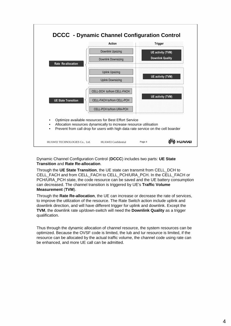
Dynamic Channel Configuration Control (DCCC) includes two parts: UE State Transition and Rate Re-allocation .
Through the UE State Transition , the UE state can transmit from CELL_DCH to CELL_FACH and from CELL_FACH to CELL_PCH/URA_PCH. In the CELL_FACH or PCH/URA_PCH state, the code resource can be saved and the UE battery consumption can decreased. The channel transition is triggered by UE’s Traffic Volume Measurement (TVM).
Through the Rate Re-allocation , the UE can increase or decrease the rate of services, to improve the utilization of the resource. The Rate Switch action include uplink and downlink direction, and will have different trigger for uplink and downlink. Except the TVM, the downlink rate up/down-switch will need the Downlink Quality as a trigger qualification.
Thus through the dynamic allocation of channel resource, the system resources can be optimized. Because the OVSF code is limited, the Iub and Iur resource is limited, if the resource can be allocated by the actual traffic volume, the channel code using rate can be enhanced, and more UE call can be admitted.
5
HUAWEI TECHNOLOGIES Co., Ltd. HUAWEI Confidential Page 5
DCCC - (TVM) Traffic Volume Measurement
TVM 4A
THRESHOLD
Taffic Volume > Tho
Threshold
Time
Transport channeltraffic volume
Event 4a Event 4a
Pending time after triggered
TVM:
The monitored traffic volume corresponds to
the amount of data in number of bytes that is
available for transmission and
retransmission in RLC layer- Buffer
Occupancy.
Timer to Trigger:
Indicates the period of time during which the
event condition has to be satisfied, before
sending a Measurement Report
Pending Time after trigger:
Indicates the period of time during which it is
forbidden to send any new measurement
reports with the same Traffic volume event
identity even if the triggering condition is
fulfilled. Time in milliseconds
TYPRABDCCCMC.Class
RAB&SRBClass
Threshold
Time
Transport channeltraffic volume
Event 4b
Event 4b
Timer to Trigger
Taffic Volume < Tho
TVM 4B
THRESHOLD
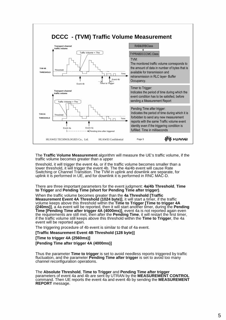
The Traffic Volume Measurement algorithm will measure the UE’s traffic volume, if the traffic volume becomes greater than a upperthreshold, it will trigger the event 4a, or if the traffic volume becomes smaller than a lower threshold, it will trigger the event 4b. The the 4a/4b event will cause Rate Switching or Channel Transition. The TVM in uplink and downlink are separate, for uplink it is performed in UE, and for downlink it is performed in RNC MAC-D.
There are three important parameters for the event judgment: 4a/4b Threshold , Time to Trigger and Pending Time (short for Pending Time after trigger) . When the traffic volume becomes greater than the 4a Threshold [Traffic Measurement Event 4A Threshold (1024 byte)] , it will start a timer, if the traffic volume keeps above this threshold within the Time to Trigger [Time to trigger 4A (240ms)] , a 4a event will be reported, then it will start another timer, during the Pending Time [Pending Time after trigger 4A (4000ms)] , event 4a is not reported again even the requirements are still met, then after the Pending Time , it will restart the first timer, if the traffic volume still keeps above this threshold within the Time to Trigger , the 4a event will be reported again. The triggering procedure of 4b event is similar to that of 4a event. [Traffic Measurement Event 4B Threshold (128 byte)][Time to trigger 4A (2560ms)][Pending Time after trigger 4A (4000ms)]
Thus the parameter Time to trigger is set to avoid needless reports triggered by traffic fluctuation, and the parameter Pending Time after trigger is set to avoid too many channel reconfiguration operations.
The Absolute Threshold , Time to Trigger and Pending Time after triggerparameters of event 4a and 4b are sent by UTRAN by the MEASUREMENT CONTROL command. Then UE reports the event 4a and event 4b by sending the MEASUREMENT REPORT message.
6
HUAWEI TECHNOLOGIES Co., Ltd. HUAWEI Confidential Page 6
DCCC - Rating Re-allocation
Rate Re-allocation – Uplink
Rate
Time
Uplink mid bitrate threshold
Uplink bitrate threshold for DCCC
Event 4b
The highest rate
Allocated rate
Event 4b Event 4a Event 4a
Adjust level =3
Adjust level =2
Traffic Volume Report from UE, Event 4a and Event 4b
- Event 4a: Traffic volume is above a threshold for a configurable time -> High active- Event 4b: Traffic volumes is below a threshold for a configurable time ->Low active
Uplink mid bitrate threshold
Uplink Rate adjust level
--- 2 or 3
Uplink mid bite rate calculate method
--- valid if adjust level is 3
Uplink bit rate threshold for DCCC
--- 8kbps to 384kbps
SET DCCCMaximum bit rate
UE activity
Uplink UpsizingUplink DownsizingDCCC.Class
GlobalParaClass
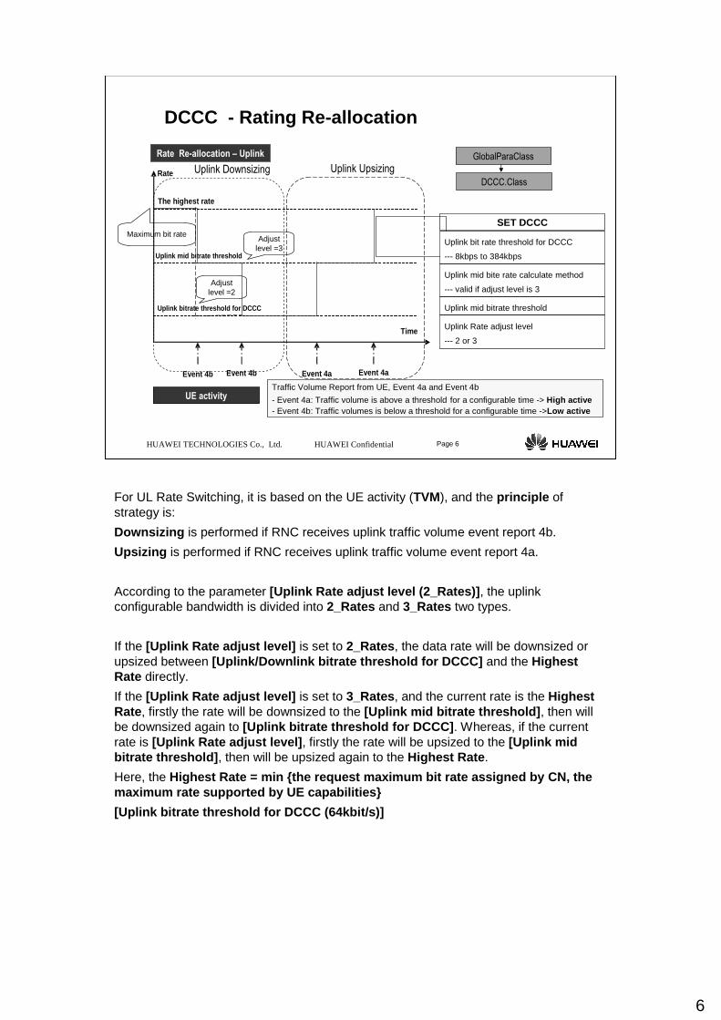
For UL Rate Switching, it is based on the UE activity (TVM), and the principle of strategy is:
Downsizing is performed if RNC receives uplink traffic volume event report 4b.
Upsizing is performed if RNC receives uplink traffic volume event report 4a.
According to the parameter [Uplink Rate adjust level (2_Rates)] , the uplink configurable bandwidth is divided into 2_Rates and 3_Rates two types.
If the [Uplink Rate adjust level] is set to 2_Rates, the data rate will be downsized or upsized between [Uplink/Downlink bitrate threshold for DCCC] and the Highest Rate directly.
If the [Uplink Rate adjust level] is set to 3_Rates, and the current rate is the Highest Rate, firstly the rate will be downsized to the [Uplink mid bitrate threshold] , then will be downsized again to [Uplink bitrate threshold for DCCC] . Whereas, if the current rate is [Uplink Rate adjust level] , firstly the rate will be upsized to the [Uplink mid bitrate threshold] , then will be upsized again to the Highest Rate .
Here, the Highest Rate = min {the request maximum bit rate as signed by CN, the maximum rate supported by UE capabilities}
[Uplink bitrate threshold for DCCC (64kbit/s)]
7
HUAWEI TECHNOLOGIES Co., Ltd. HUAWEI Confidential Page 7
DCCC - Rating Switching
Rate Re-allocation – Downlink triggered by UE activity
Adjust level =3
Adjust level =2
DOWNLINK MID BITRATE
THRESHOLD
Downlink Rate adjust level
--- 2 or 3
Downlink mid bite rate calculate method
--- valid if adjust level is 3
Downlink Bit rate threshold for DCCC
--- 8kbps to 384kbps
SET DCCCMaximum bit rate Rate
Time
Downlink mid bitrate threshold
Downlink bitrate threshold for DCCC
Event 4b
The highest rate
Allocated rate
Event 4a Event 4aEvent 4b
4BMONITIME 4BMONITIME
Traffic Volume Report, Event 4a and Event 4b in RNC
- Event 4a: Traffic volume is above a threshold for a configurable time -> High active- Event 4b: Traffic volumes is below a threshold for a configurable time-> Low active
Downlink rate up-switchDownlink rate down-switch
DCCC.Class
GlobalParaClass
CELLDCCC.Class
CellClass
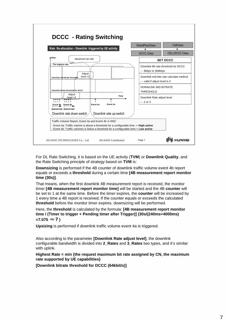
For DL Rate Switching, it is based on the UE activity (TVM) or Downlink Quality , and the Rate Switching principle of strategy based on TVM is:
Downsizing is performed if the 4B counter of downlink traffic volume event 4b report equals or exceeds a threshold during a certain time [4B measurement report monitor time (30s)] .
That means, when the first downlink 4B measurement report is received, the monitor timer [4B measurement report monitor time] will be started and the 4B counter will be set to 1 at the same time. Before the timer expires, the counter will be increased by 1 every time a 4B report is received; If the counter equals or exceeds the calculatedthreshold before the monitor timer expires, downsizing will be performed.
Here, the threshold is calculated by the formula: [4B measurement report monitor time / (Timer to trigger + Pending timer after Trig ger)] (30s/(240ms+4000ms) =7.075 ≈≈≈≈ 7 )
Upsizing is performed if downlink traffic volume event 4a is triggered.
Also according to the parameter [Downlink Rate adjust level] , the downlink configurable bandwidth is divided into 2_Rates and 3_Rates two types, and it’s similar with uplink.
Highest Rate = min {the request maximum bit rate as signed by CN, the maximum rate supported by UE capabilities}
[Downlink bitrate threshold for DCCC (64kbit/s)]
8
HUAWEI TECHNOLOGIES Co., Ltd. HUAWEI Confidential Page 8
DCCC - Rating Switching
Rate Re-allocation – Downlink triggered by Downlink Quality
Transmit power and RLC retransmission report: Event E/F and Event A- Event Ea: Transmit power rises above measurement threshold 1 and Node B send TCP meas. report- Event Eb: transmit power falls below measurement threshold 2 and Node B stop sending TCP meas. Report- Event Fa: Transmit power falls below measurement threshold 1 - Event Fb: Transmit power rises above measurement threshold 2- Event A : RLC retransmission value is above threshold for a period
Rate
Time
Event Eaand Event A
Allocated rate
Event Eaand Event A
Downlink mid bitrate threshold
Downlink bitrate threshold for DCCC
The highest rate
Event Eb relative threshold
Event Ea relative threshold
Downlink BE guarantee bit rate
--- 8kbps to 384kbps
SET DCCC
UE with high speed service is subject to
drop due to high TCP
Event A threshold
Event A pending time after trigger
Event A time to trigger
ADD TYPRABRLC
Downlink rate down-switch
Downlink BE guarantee bit rate
DCCC.Class
GlobalParaClass
TYPRABRLC.Class
RAB&SRBClass
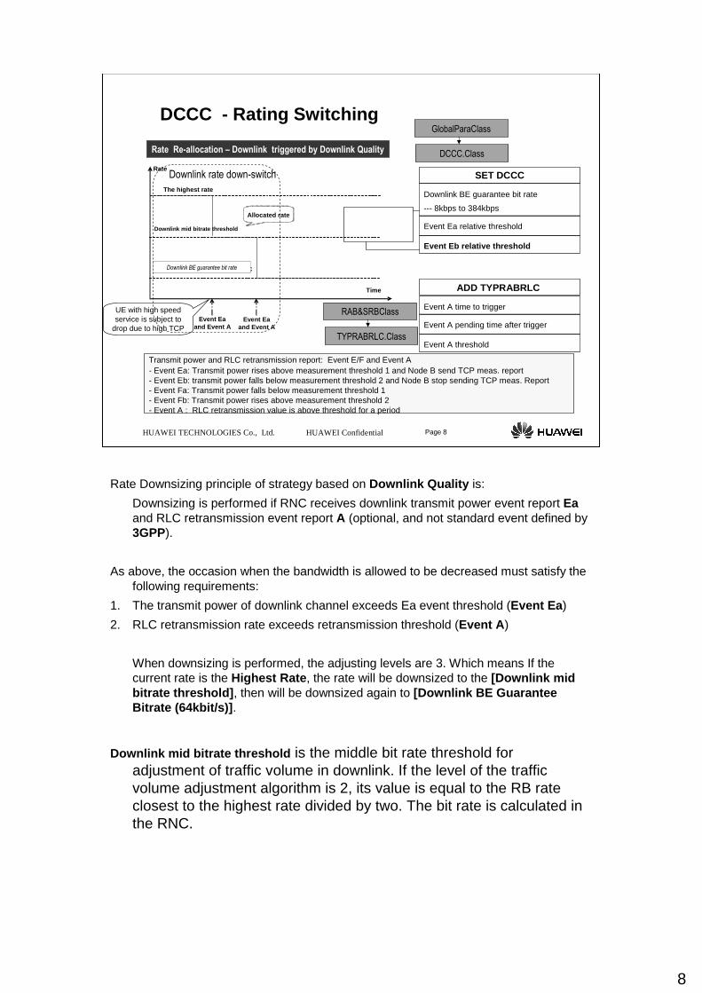
Rate Downsizing principle of strategy based on Downlink Quality is:
Downsizing is performed if RNC receives downlink transmit power event report Eaand RLC retransmission event report A (optional, and not standard event defined by 3GPP).
As above, the occasion when the bandwidth is allowed to be decreased must satisfy the following requirements:
1. The transmit power of downlink channel exceeds Ea event threshold (Event Ea )
2. RLC retransmission rate exceeds retransmission threshold (Event A )
When downsizing is performed, the adjusting levels are 3. Which means If the current rate is the Highest Rate , the rate will be downsized to the [Downlink mid bitrate threshold] , then will be downsized again to [Downlink BE Guarantee Bitrate (64kbit/s)] .
Downlink mid bitrate threshold is the middle bit rate threshold for adjustment of traffic volume in downlink. If the level of the traffic volume adjustment algorithm is 2, its value is equal to the RB rate closest to the highest rate divided by two. The bit rate is calculated in the RNC.
9
HUAWEI TECHNOLOGIES Co., Ltd. HUAWEI Confidential Page 9
DCCC - Rating Switching
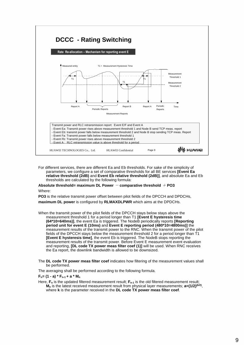
Rate Re-allocation – Mechanism for reporting event E
Transmit power and RLC retransmission report: Event E/F and Event A- Event Ea: Transmit power rises above measurement threshold 1 and Node B send TCP meas. report- Event Eb: transmit power falls below measurement threshold 2 and Node B stop sending TCP meas. Report- Event Fa: Transmit power falls below measurement threshold 1 - Event Fb: Transmit power rises above measurement threshold 2- Event A : RLC retransmission value is above threshold for a period
T1T1
Measured entity
Time
T1
Report A Report B Report A
Measurement Reports
T1 = Measurement Hysteresis Time
Periodic Reports
Measurement
Threshold 2
Measurement
Threshold 1
Periodic
Reports
For different services, there are different Ea and Eb thresholds. For sake of the simplicity of parameters, we configure a set of comparative thresholds for all BE services [Event Ea relative threshold (2dB) and Event Eb relative threshold (2dB)] , and absolute Ea and Ebthresholds are calculated by the following formula:
Absolute threshold= maximum DL Power - comparative threshold + PO3 Where:PO3 is the relative transmit power offset between pilot fields of the DPCCH and DPDCHs, maximum DL power is configured by RLMAXDLPWR which aims at the DPDCHs.
When the transmit power of the pilot fields of the DPCCH stays below stays above the measurement threshold 1 for a period longer than T1 [Event E hysteresis time (64*10=640ms)] , the event Ea is triggered. The NodeB periodically reports [Reporting period unit for event E (10ms) and Event E reporting period (480*10=4800ms)] the measurement results of the transmit power to the RNC. When the transmit power of the pilot fields of the DPCCH stays below the measurement threshold 2 for a period longer than T1 [Event E hysteresis time] , the event Eb is triggered. The NodeB stops reporting the measurement results of the transmit power. Before Event E measurement event evaluation and reporting, [DL code TX power meas filter coef (1)] will be used. When RNC receives the Ea report, the downlink bandwidth is allowed to be downsized.
The DL code TX power meas filter coef indicates how filtering of the measurement values shall be performed.
The averaging shall be performed according to the following formula.Fn= (1 - a) * Fn-1 + a * Mn
Here, Fn is the updated filtered measurement result; Fn-1 is the old filtered measurement result; Mn is the latest received measurement result from physical layer measurements; a=(1/2)(k/2), where k is the parameter received in the DL code TX power meas filter coef .
10
HUAWEI TECHNOLOGIES Co., Ltd. HUAWEI Confidential Page 10
DCCC - Rating Switching
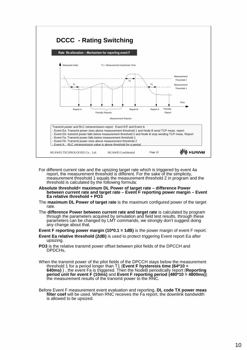
Rate Re-allocation – Mechanism for reporting event F
Transmit power and RLC retransmission report: Event E/F and Event A- Event Ea: Transmit power rises above measurement threshold 1 and Node B send TCP meas. report- Event Eb: transmit power falls below measurement threshold 2 and Node B stop sending TCP meas. Report- Event Fa: Transmit power falls below measurement threshold 1 - Event Fb: Transmit power rises above measurement threshold 2- Event A : RLC retransmission value is above threshold for a period
T1
T1
Measured entity
Time
Measurement Reports
Measurement
Threshold 2
Measurement
Threshold 1
T1 = Measurement Hysteresis Time
T1
Report A Report B
Periodic Reports
Report A Periodic
Report
For different current rate and the upsizing target rate which is triggered by event 4a report, the measurement threshold is different. For the sake of the simplicity, measurement threshold 1 equals the measurement threshold 2 in program and the threshold is calculated by the following formula:
Absolute threshold= maximum DL Power of target rate – difference Power between current rate and target rate – Event F repor ting power margin – Event Ea relative threshold + PO3
The maximum DL Power of target rate is the maximum configured power of the target rate.
The difference Power between current rate and target ra te is calculated by program through the parameters acquired by simulation and field test results, through these parameters can be changed by LMT commands, we strongly don’t suggest doing any change about that.
Event F reporting power margin (10*0.1 = 1dB) is the power margin of event F report. Event Ea relative threshold (2dB) is used to protect triggering Event report Ea after
upsizing. PO3 is the relative transmit power offset between pilot fields of the DPCCH and
DPDCHs,
When the transmit power of the pilot fields of the DPCCH stays below the measurement threshold 1 for a period longer than T1 (Event F hysteresis time (64*10 = 640ms) ) , the event Fa is triggered. Then the NodeB periodically report (Reporting period unit for event F (10ms) and Event F reporting period (480*10 = 4800ms) ) the measurement results of the transmit power to the RNC.
Before Event F measurement event evaluation and reporting, DL code TX power measfilter coef will be used. When RNC receives the Fa report, the downlink bandwidth is allowed to be upsized.
11
HUAWEI TECHNOLOGIES Co., Ltd. HUAWEI Confidential Page 11
DCCC - Rating Switching
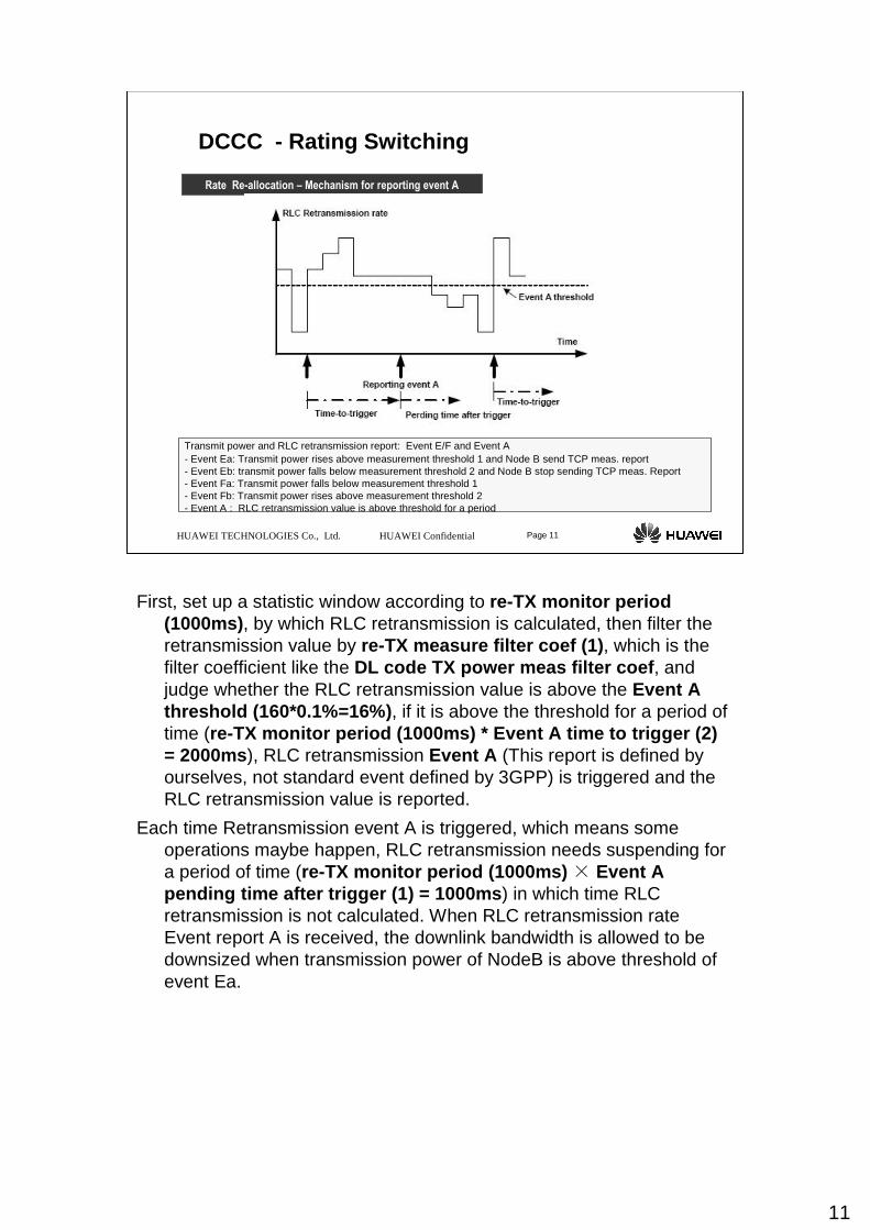
Rate Re-allocation – Mechanism for reporting event A
Transmit power and RLC retransmission report: Event E/F and Event A- Event Ea: Transmit power rises above measurement threshold 1 and Node B send TCP meas. report- Event Eb: transmit power falls below measurement threshold 2 and Node B stop sending TCP meas. Report- Event Fa: Transmit power falls below measurement threshold 1 - Event Fb: Transmit power rises above measurement threshold 2- Event A : RLC retransmission value is above threshold for a period
First, set up a statistic window according to re-TX monitor period (1000ms) , by which RLC retransmission is calculated, then filter the retransmission value by re-TX measure filter coef (1) , which is the filter coefficient like the DL code TX power meas filter coef , and judge whether the RLC retransmission value is above the Event A threshold (160*0.1%=16%) , if it is above the threshold for a period of time (re-TX monitor period (1000ms) * Event A time to tri gger (2) = 2000ms ), RLC retransmission Event A (This report is defined by ourselves, not standard event defined by 3GPP) is triggered and the RLC retransmission value is reported.
Each time Retransmission event A is triggered, which means some operations maybe happen, RLC retransmission needs suspending fora period of time (re-TX monitor period (1000ms) × Event A pending time after trigger (1) = 1000ms ) in which time RLC retransmission is not calculated. When RLC retransmission rate Event report A is received, the downlink bandwidth is allowed to be downsized when transmission power of NodeB is above threshold of event Ea.
12
1. The UE state transition from CELL_DCH to CELL_FACHWhen the RNC receives the report event 4b about the decrease of the UE activity, and the traffic volume of event report 4b is zero, it starts a timer. If both uplink and downlink Counterof traffic volume event 4b equal or exceed a threshold before a timer expires. [The timer can be DCH to FACH transition timer (180s) or BE HS-DSCH to FACH transition timer (180s) or Realtime Traff DCH or HS-DSCH to FACH transition timer (180s) ], then when the timer expires, the UE state transits from CELL_FACH to CELL_PCH.
* Here,
The DCH to FACH transition timer is used when the service type is BE and allocated channel type is DCH.
The BE HS-DSCH to FACH transition timer is used when the service type is BE and allocated channel type is HS-DSCH.
The Realtime Traff DCH or HS-DSCH to FACH transition time r is used when the service type is PS RT
The threshold is calculated by the formula: The threshold is calculated by the formula:[4B measurement report monitor time / (Timer to tri gger + Pending timer after Trigger)*
State trans traff redund coef (80%)]
For DCH to FACH, 180s/(5000ms+16000ms)*80% = 6.85 ≈≈≈≈ 6
2. The UE state transition from CELL_FACH to CELL_PCHWhen the RNC receives the report event 4b about the decrease of the UE activity, and the traffic volume of event report 4b is zero, it starts a timer. If both uplink and downlink Counterof traffic volume event 4b equal or exceed a threshold before a timer expires. [FACH to PCH transition timer (180s)] , then when the timer expires, the UE state transits from CELL_FACH to CELL_PCH.
* Here, the threshold is calculated by the formula: [FACH to PCH Transition Timer / (FACH to PCH 4B tim e to trigger + FACH to PCH 4B
Pending Time after trigger)* State trans traff redun d coef ]
180s/(5000ms+16000ms)*80% = 6.85 ≈≈≈≈ 6
• The UE state transition from CELL_PCH to URA_PCHWhen UE is in CELL_PCH state, during the cell reselection, the UE sends the Cell Update messages. The RNC starts a timer [CELL reselection timer (180s)] and counts the number of the Cell Update messages. When the timer expires, the number of the Cell Update messages may exceed the threshold [Cell reselection counter (9)] . In that case, the RNC initiates the state transition CELL_PCH to URA_PCH, when the UE sends the CELL UPDATE message again.
4. The UE state transition from CELL_PCH or URA_PCH to CELL_FACHThe state of the UE transits to CELL_FACH when the UE initiates the cell update process or when the UE is paged by UTRAN and the UE needs to exchange messages with the network side.
5. The UE state transition from CELL_FACH to CELL_DCHThe state of the UE transits to CELL_DCH when the URTAN receives the UL or DL the traffic volume exceeds a threshold [BE FACH to DCH 4A threshold (1024byte) or BE FACH to HS-DSCH 4A threshold (1024byte) or Realtime Traff FACH to DCH 4A threshold (1024byte)] .
all time to trigger (240ms)
13
HUAWEI TECHNOLOGIES Co., Ltd. HUAWEI Confidential Page 13
DCCC - Parameters StructureRNC
RadioClass
GlobalParaClass CellClass
TYPRABBASIC.Class
TYPRABDCCCMC.Class
TYPRABRLC.Class
DCCC.Class
CELLDCCC.ClassUESTATETRANS.Class
RAB&SRBClass
Direction
Traffic Measurement Event 4B threshold
Traffic Measurement Event 4A threshold
Time to trigger 4B
Time to trigger 4A
Pending time after trigger 4B
Pending time after trigger 4A
4B measurement report monitor time
re-TX monitor period
re-TX measure filter coef
Event A threshold
Event A time to trigger
Event A pending time after trigger
RAB&SRBClass
TYPRABBASIC.ClassTYPRABDCCCMC.Class TYPRABRLC.Class
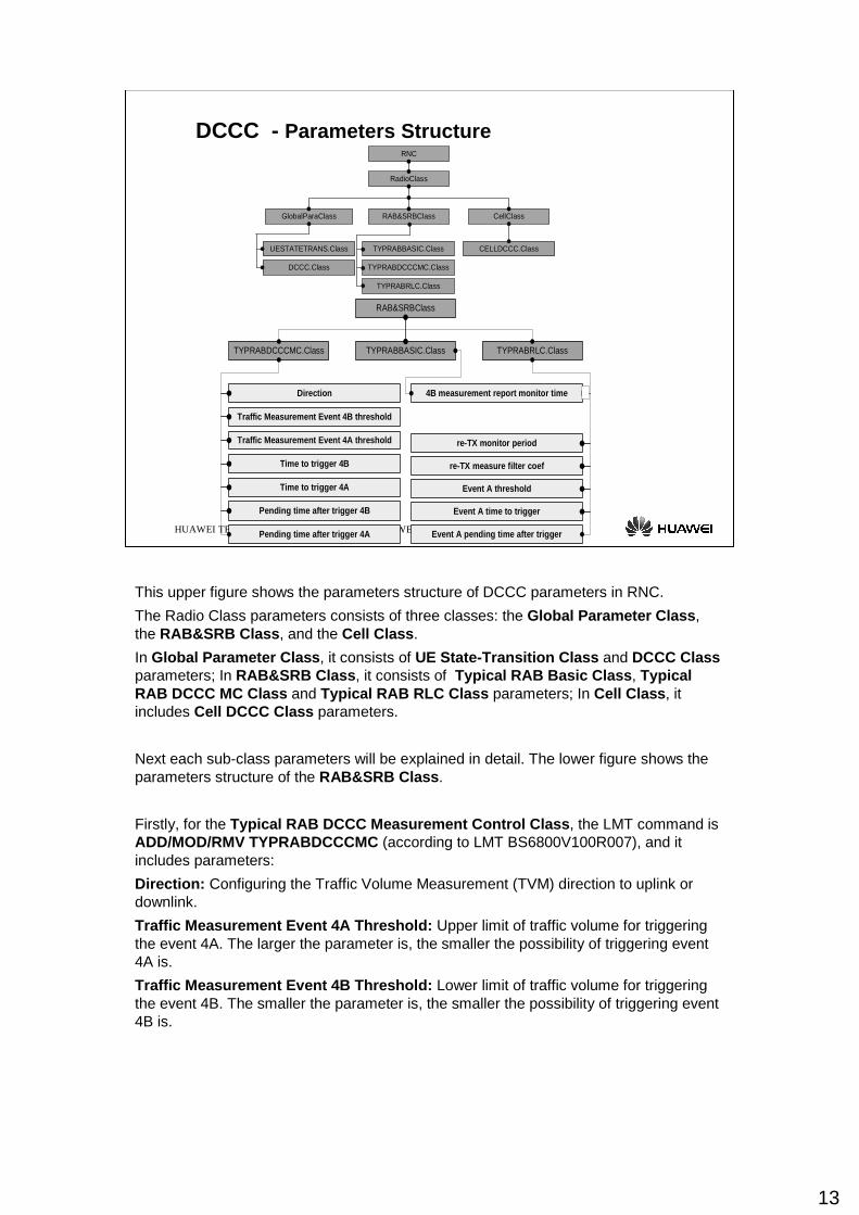
This upper figure shows the parameters structure of DCCC parameters in RNC.
The Radio Class parameters consists of three classes: the Global Parameter Class , the RAB&SRB Class , and the Cell Class .
In Global Parameter Class , it consists of UE State-Transition Class and DCCC Classparameters; In RAB&SRB Class , it consists of Typical RAB Basic Class , Typical RAB DCCC MC Class and Typical RAB RLC Class parameters; In Cell Class , it includes Cell DCCC Class parameters.
Next each sub-class parameters will be explained in detail. The lower figure shows the parameters structure of the RAB&SRB Class.
Firstly, for the Typical RAB DCCC Measurement Control Class , the LMT command is ADD/MOD/RMV TYPRABDCCCMC (according to LMT BS6800V100R007), and it includes parameters:
Direction : Configuring the Traffic Volume Measurement (TVM) direction to uplink or downlink.
Traffic Measurement Event 4A Threshold : Upper limit of traffic volume for triggering the event 4A. The larger the parameter is, the smaller the possibility of triggering event 4A is.
Traffic Measurement Event 4B Threshold : Lower limit of traffic volume for triggering the event 4B. The smaller the parameter is, the smaller the possibility of triggering event 4B is.
14
Time to trigger 4A : Time period during which the traffic volume is above the upper limit before the event 4A is triggered. This parameter is set to avoid needless reports triggered by traffic fluctuation. The larger the parameter is, the longer the required time to exceed the upper threshold is, and the smaller the possibility of triggering event 4A is.
Time to trigger 4B : Time period during which the traffic volume is below the lower limit before the event 4B is triggered. This parameter is set to avoid needless reports triggered by traffic fluctuation. The larger the parameter is, the longer the required time to be under the lower threshold is, and the smaller the possibility of triggering event 4B is.
Pending time after trigger 4A : Time period during which the event 4A is not reported after an event 4A is triggered. This parameter is used to avoid too many channel reconfiguration operations. The larger the value of this parameter, the longer the pending time, and the harder the event 4A is triggered.
Pending time after trigger 4B : Time period during which the event 4B is not reported after an event 4B is triggered. This parameter is set to avoid too many channel reconfiguration operations. The larger the value of this parameter, the longer the pending time, and the harder the event 4B is triggered.
Secondary, for the Typical RAB Basic Class , the LMT command is MOD/RMV TYPRAB , and it includes parameter:
4B measurement report monitor time : This parameter defines the time in which the DL 4B traffic volume measurement reports are monitored. If DL 4B measurement reports are received successively, RNC will reduce the DL bandwidth.
Thirdly, for the Typical RAB RLC Class , the LMT command is ADD/MOD/RMV TYPRABRLC , and it includes parameters:
Re-TX monitor period : A period for re-transmitted PUD monitor. Time of a period for re-transmitted PDU monitor when the RLC entity is established or reconfigured.
Re-TX measure filter coef : Re-TX measure filter coefficient. RLC retransmission measurement filter coefficient.
Event A threshold : Threshold of event A, which indicates a high ratio of PDUs are re-transmitted.
Event A time to trigger : Times of period to trigger event A. Event A is triggered only when the ratio of re-transmitted PDUs is higher than the threshold of event A in several times of period.
Event A pending time after trigger : Pending times of period after event A is triggered. During the period, no event of re-transmitted PDUs is reported.
15
HUAWEI TECHNOLOGIES Co., Ltd. HUAWEI Confidential Page 15
DCCC - Parameters Structure
DCCC strategy
Uplink bitrate threshold for DCCC
Uplink mid bite rate calculate method
Uplink mid bitrate threshold
Uplink Rate adjust level
Downlink bitrate threshold for DCCC
Downlink mid bite rate calculate method
Downlink mid bitrate threshold
Downlink BE guarantee bitrate
Event F hysteresis time
Reporting period unit for event F
Event F reporting period[ms]
Event F reporting period[min]
Event Ea relative threshold
Event Eb relative threshold
Event E hysteresis time
Reporting period unit for event E
Event E reporting period[ms]
Event E reporting period[min]
GlobalParaClassUESTATETRANS.Class DCCC.Class
DCH to FACH transition timer
BE HS-DSCH to FACH transition timer
Realtime Traff DCH to FACH transition timer
FACH to PCH transition timer
Cell reselection timer
Cell reselection counter
BE FACH to DCH 4A threshold
BE FACH to HS-DSCH 4A threshold
Realtime Traff DCH to FACH 4B threshold
Downlink Rate adjust level
CellClass
CELLDCCC.Class
Downlink BE guarantee bitrate
Event F hysteresis time
Reporting period unit for event F
Event F reporting period[ms]
Event F reporting period[min]
Event E hysteresis time
Reporting period unit for event E
Event E reporting period[ms]
Event E reporting period[min]
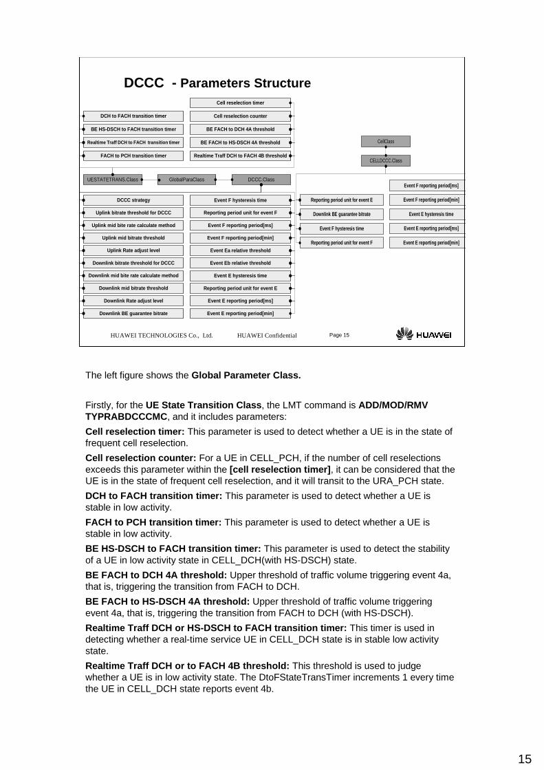
The left figure shows the Global Parameter Class .
Firstly, for the UE State Transition Class , the LMT command is ADD/MOD/RMV TYPRABDCCCMC , and it includes parameters:
Cell reselection timer : This parameter is used to detect whether a UE is in the state of frequent cell reselection.
Cell reselection counter : For a UE in CELL_PCH, if the number of cell reselections exceeds this parameter within the [cell reselection timer] , it can be considered that the UE is in the state of frequent cell reselection, and it will transit to the URA_PCH state.
DCH to FACH transition timer : This parameter is used to detect whether a UE is stable in low activity.
FACH to PCH transition timer : This parameter is used to detect whether a UE is stable in low activity.
BE HS-DSCH to FACH transition timer : This parameter is used to detect the stability of a UE in low activity state in CELL_DCH(with HS-DSCH) state.
BE FACH to DCH 4A threshold : Upper threshold of traffic volume triggering event 4a, that is, triggering the transition from FACH to DCH.
BE FACH to HS-DSCH 4A threshold : Upper threshold of traffic volume triggering event 4a, that is, triggering the transition from FACH to DCH (with HS-DSCH).
Realtime Traff DCH or HS-DSCH to FACH transition tim er: This timer is used in detecting whether a real-time service UE in CELL_DCH state is in stable low activity state.
Realtime Traff DCH or to FACH 4B threshold : This threshold is used to judge whether a UE is in low activity state. The DtoFStateTransTimer increments 1 every time the UE in CELL_DCH state reports event 4b.
16
Secondary, for the DCCC Class , the LMT command is SET/LST DCCC, and it includes parameters:
Uplink bitrate threshold for DCCC : The DCCC algorithm capability may be very low for some Best Effort (BE) service with very low applied maximum rate. The UL DCCC algorithm does not activate for the BE service whose applied uplink maximum rate is smaller than or equal to the threshold.
Downlink bitrate threshold for DCCC : The DCCC algorithm capability may be very low for some Best Effort (BE) service with very low applied maximum rate. The DL DCCC algorithm does not activate for the BE service whose applied downlink maximum rate is smaller than or equal to the threshold.
DCCC strategy : The velocity of PS BE services adjust strategy in CELL_DCH state. RATE_UP_AND_DWON strategy permit velocity rate up and rate down. RATE_UP_ONLY strategy just permit velocity rate up. This means UE can transit from CELL_DCH to CELL_FACH state at any velocity .
Event Ea relative threshold : Together with the maximum transmit power, it determines the event Ea threshold of the DL DPCCH power.
Event Eb relative threshold : Together with the maximum transmit power, it determines the event Eb threshold of the DL DPCCH power.
Event E hysteresis time : The time allowance for the situation where the measured power is higher than the threshold, so as to avoid the misreporting due to erratic fluctuation. However, to avoid too more delay, this parameter cannot be set too great. If it is set as A, the hysteresis time is A*10ms.
Reporting period unit for event E (ChoiceRptUnitForE ): The DL code TX power (if any) will be reported periodically after the event Ea is reported. The reporting period unit can be 10 ms or min.
Event E reporting period in 10ms : Valid when the parameter ChoiceRptUnitForE is set as TEN_MSEC. The DL code TX power (if any) will be reported periodically after the event Ea is reported. If it is set as A, the reporting period is A*10ms.
Event E reporting period in min : Valid when the parameter ChoiceRptUnitForE is set as MIN. The DL code TX power (if any) will be reported periodically after the event E is reported. This parameter is to specify the reporting period.
Event F hysteresis time : The time allowance for the situation where the measured power is lower than the threshold, so as to avoid the misreporting due to erratic fluctuation. However, to avoid too more delay, this parameter cannot be set too great. If it is set as A, the hysteresis time is A*10ms.
Reporting period unit for event F : The DL code TX power (if any) will be reported periodically after the event Fa is reported. The reporting period unit can be 10 ms or min.
Event F reporting period in 10ms : Valid when the parameter ChoiceRptUnitForF is set as TEN_MSEC. The DL code TX power (if any) will be reported periodically after the event Fa is reported. If it is set as A, the reporting period is A*10ms.
Event F reporting period in min : Valid when the parameter ChoiceRptUnitForE is set as MIN. The DL code TX power (if any) will be reported periodically after the event F is reported. This parameter is to specify the reporting period.
Downlink BE guarantee bitrate : The default downlink BE guarantee bit rate of the cell. In radio network planning, the bitrate may be supported in whole cell. The downlink bitrate of BE service will be reduced to this bitrate when the DL transmit code power is higher than the threshold of the event Ea. When fails to get the DCCC parameters of best cell, default value will be used.
17
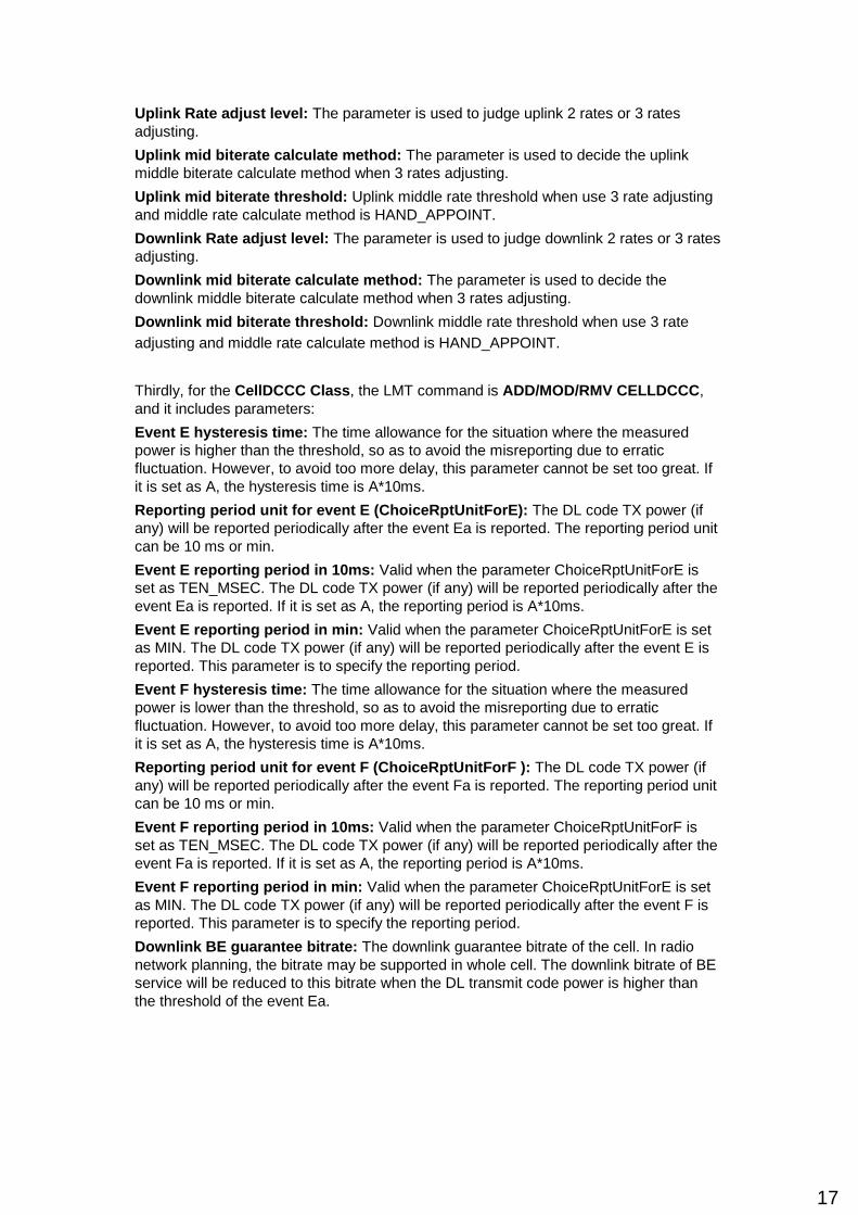
Uplink Rate adjust level : The parameter is used to judge uplink 2 rates or 3 rates adjusting.
Uplink mid biterate calculate method : The parameter is used to decide the uplink middle biterate calculate method when 3 rates adjusting.
Uplink mid biterate threshold : Uplink middle rate threshold when use 3 rate adjusting and middle rate calculate method is HAND_APPOINT.
Downlink Rate adjust level : The parameter is used to judge downlink 2 rates or 3 rates adjusting.
Downlink mid biterate calculate method : The parameter is used to decide the downlink middle biterate calculate method when 3 rates adjusting.
Downlink mid biterate threshold : Downlink middle rate threshold when use 3 rate adjusting and middle rate calculate method is HAND_APPOINT.
Thirdly, for the CellDCCC Class , the LMT command is ADD/MOD/RMV CELLDCCC , and it includes parameters:
Event E hysteresis time : The time allowance for the situation where the measured power is higher than the threshold, so as to avoid the misreporting due to erratic fluctuation. However, to avoid too more delay, this parameter cannot be set too great. If it is set as A, the hysteresis time is A*10ms.
Reporting period unit for event E (ChoiceRptUnitForE ): The DL code TX power (if any) will be reported periodically after the event Ea is reported. The reporting period unit can be 10 ms or min.
Event E reporting period in 10ms : Valid when the parameter ChoiceRptUnitForE is set as TEN_MSEC. The DL code TX power (if any) will be reported periodically after the event Ea is reported. If it is set as A, the reporting period is A*10ms.
Event E reporting period in min : Valid when the parameter ChoiceRptUnitForE is set as MIN. The DL code TX power (if any) will be reported periodically after the event E is reported. This parameter is to specify the reporting period.
Event F hysteresis time : The time allowance for the situation where the measured power is lower than the threshold, so as to avoid the misreporting due to erratic fluctuation. However, to avoid too more delay, this parameter cannot be set too great. If it is set as A, the hysteresis time is A*10ms.
Reporting period unit for event F (ChoiceRptUnitForF ): The DL code TX power (if any) will be reported periodically after the event Fa is reported. The reporting period unit can be 10 ms or min.
Event F reporting period in 10ms : Valid when the parameter ChoiceRptUnitForF is set as TEN_MSEC. The DL code TX power (if any) will be reported periodically after the event Fa is reported. If it is set as A, the reporting period is A*10ms.
Event F reporting period in min : Valid when the parameter ChoiceRptUnitForE is set as MIN. The DL code TX power (if any) will be reported periodically after the event F is reported. This parameter is to specify the reporting period.
Downlink BE guarantee bitrate : The downlink guarantee bitrate of the cell. In radio network planning, the bitrate may be supported in whole cell. The downlink bitrate of BE service will be reduced to this bitrate when the DL transmit code power is higher than the threshold of the event Ea.
18
HUAWEI TECHNOLOGIES Co., Ltd. HUAWEI Confidential Page 18
DCCC - Strategy
√√√√(D to F)RATE_UP_ONLY
Step 2 (D to F)
√√√√( D to F )
Channel
Transition
Step 1 (D to D)RATE_UP_AND_DOWNRequested RAB rate > DOWNLINK BITRATE THRESHOLD
FOR DCCC or UPLINK BITRATE THRESHOLD FOR DCCC
Requested RAB rate < DOWNLINK BITRATE THRESHOLD
FOR DCCC or UPLINK BITRATE THRESHOLD FOR DCCC
Rate SwitchingStrategy
DCCC.Class
GlobalParaClass
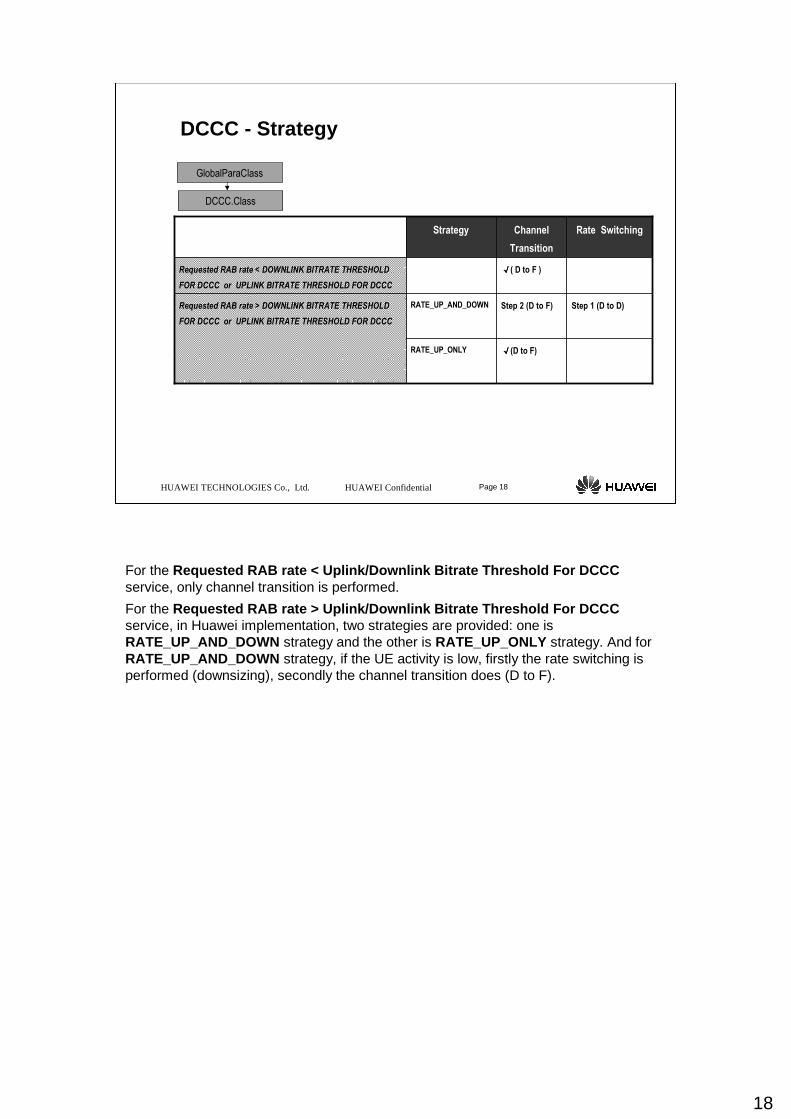
For the Requested RAB rate < Uplink/Downlink Bitrate Thresho ld For DCCCservice, only channel transition is performed.
For the Requested RAB rate > Uplink/Downlink Bitrate Thresho ld For DCCC service, in Huawei implementation, two strategies are provided: one is RATE_UP_AND_DOWN strategy and the other is RATE_UP_ONLY strategy. And for RATE_UP_AND_DOWN strategy, if the UE activity is low, firstly the rate switching is performed (downsizing), secondly the channel transition does (D to F).
19
HUAWEI TECHNOLOGIES Co., Ltd. HUAWEI Confidential Page 19
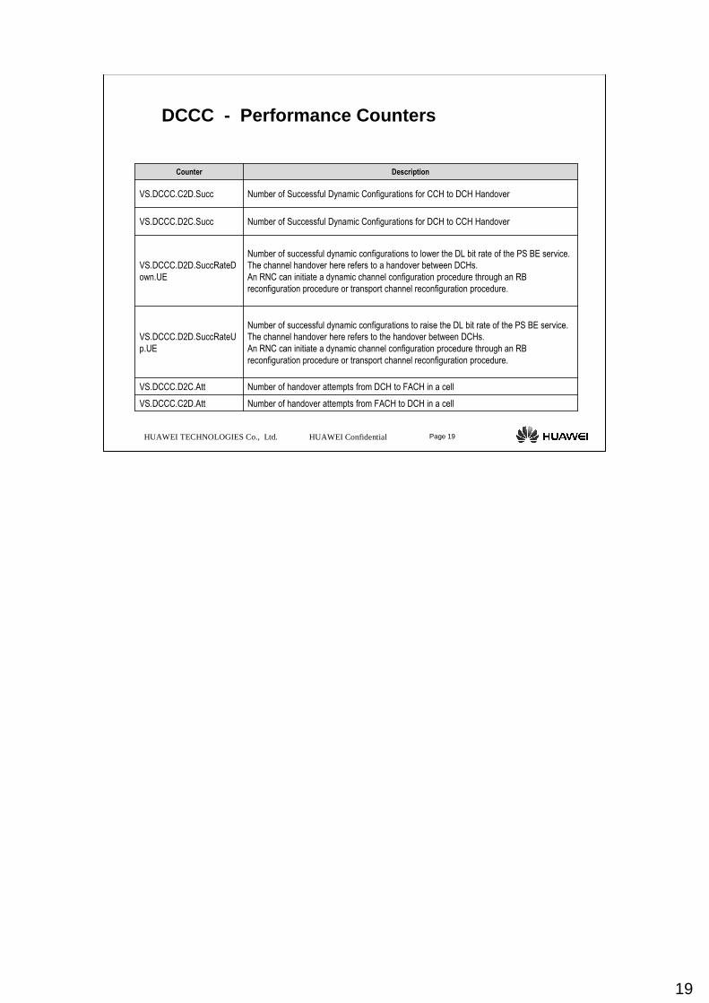
DCCC - Performance Counters
Number of handover attempts from FACH to DCH in a cellVS.DCCC.C2D.Att
Number of handover attempts from DCH to FACH in a cellVS.DCCC.D2C.Att
Number of successful dynamic configurations to raise the DL bit rate of the PS BE service.
The channel handover here refers to the handover between DCHs.
An RNC can initiate a dynamic channel configuration procedure through an RB
reconfiguration procedure or transport channel reconfiguration procedure.
VS.DCCC.D2D.SuccRateU
p.UE
Number of successful dynamic configurations to lower the DL bit rate of the PS BE service.
The channel handover here refers to a handover between DCHs.
An RNC can initiate a dynamic channel configuration procedure through an RB
reconfiguration procedure or transport channel reconfiguration procedure.
VS.DCCC.D2D.SuccRateD
own.UE
Number of Successful Dynamic Configurations for DCH to CCH Handover VS.DCCC.D2C.Succ
Number of Successful Dynamic Configurations for CCH to DCH HandoverVS.DCCC.C2D.Succ
DescriptionCounter
20
HUAWEI TECHNOLOGIES Co., Ltd. HUAWEI Confidential Page 20
Thank you!
The last but not the least. We want to use this picture to show that in this company we stress teamwork as part of corporate culture. So behind every project, there are over 24000 people supporting it.
That is a brief introduction about the company. Thank you very much.