4300/6300 series magneto maintenance and overhaul manual · overhaul manual technical aspects faa...
TRANSCRIPT
Unison Industries530 Blackhawk Park Avenue
Rockford, Illinois, U.S.A. 61104©2006 Unison Industries, Inc.
ISSUED
MO DAY YR
04 01 91
REVISED
MO DAY YR
02 28 06
PAGE NO. REVISION
CCover
L-1363C4300/6300 Series
Magneto Maintenance andOverhaul Manual
Technical AspectsFAA Approved
SCOPEThis Maintenance and Overhaul Manual provides Detailedmaintenance, assembly, disassembly and Troubleshootinginstructions and technical Information about the design andoperation of Slick Magnetos.

Unison Industries530 Blackhawk Park Avenue
Rockford, Illinois, U.S.A. 61104©2006 Unison Industries, Inc.
ISSUED
MO DAY YR
04 01 91
REVISED
MO DAY YR
02 28 06
PAGE NO. REVISION
C
L-1363
LOG OF REVISIONS
To: Holders of L-1363B, dated September 15, 1994.
Subject: Revision C, dated October 31, 2005.
1. All pages of this manual are new.
2. Changed all references to “Slick Aircraft Products” and “Slick” to “Unison Industries” and “Unison” respectivelythroughout the manual.
3. Revised pages that have important changes are shown below.
Page Number Change
Page 0-1 Changed address and added e-mail address to paragraph 0-1.
Page 0-2 In paragraph 0.3, replaced L-1177 and L-1178 with L-1499. In paragraph 0.4, added Factory TechnicalAssistance.
Page 2-1 Added T-155 Rivet Gauge to list and illustration.
Page 3-1 Deleted last sentence in paragraph 3.2.1.A
Page 3-2 Deleted paragraphs 3.2.1.B through H. Corrected figure numbers to reflect the paragraph theyreference.
Page 3-3 Deleted “Maximum” and added tolerance value to paragraph 3.2.9. Corrected figure numbers toreflect the paragraph they reference.
Page 3-4 Revised paragraphs 3.3.4.1 and 2. Inserted new paragraphs 6 through 9 and new Figures 3.3.4Aand 3.3.4B. Renumbered remaining paragraphs and figures.
Page 3-5 Revised paragraph 3.3.4.D.2.
Page 3-6 Changed paragraph 3.3.7.B to read “Condenser Inspection”. Deleted paragraph 3.3.7.B.1 andrenumbered remaining paragraphs. Moved text of paragraph 3.3.7.B.1 to renumbered paragraph3.3.7.B.3. Added NOTE after renumbered paragraph 3.3.7.B.2. Changed service limits in paragraph3.3.7.C.1. Revised paragraph 3.3.7.C.2.
Page 3-7 In paragraph 3.3.8.B.3, changed third sentence to read, “If the bushing is gummed, replace distributorblock.”. Deleted last sentence.
Page 3-8 Added orifice diameter tolerance value to paragraph 3.4.2.
Page 4-2 Added orifice diameter tolerance value to paragraph 4.2.3.
Page 7-2 Added reference to Loctite to paragraph 7.2.F. Added “(If So Equipped)” to paragraph 7.6 title.
Page 7-4 Changed gap opening to “.008 - .010 inches” in paragraph 7.10.1.E.
Page 7-5 Changed tolerance value to “± .002” in paragraph 7.10.3.B.
Page 7-6 Corrected first paragraph 7.14 to read 7.13. Inserted new paragraph 7.13.A and renumberedremaining paragraphs. Revised renumbered paragraph 7.13.C.
Page 8-1 Added “maximum” to RPM values in paragraph 8.3.B. Changed air flow rate in paragraph 8.8.
Page 9-1 Moved paragraph 9.0 from Section 8 to Section 9.
i
L-1363
Unison Industries530 Blackhawk Park Avenue
Rockford, Illinois, U.S.A. 61104©2006 Unison Industries, Inc.
ISSUED
MO DAY YR
04 01 91
REVISED
MO DAY YR
02 28 06
PAGE NO. REVISION
C
Page Number Change
Page 10-5 In Faulty Ignition Lead Remedy, replaced L-1177 with L-1499.
Pages T-2 and T-3 In Table Two, added coverage for 4309, 4310, 4333, and 4392 magnetos. Changed the “M” in item11 to “K”. “M2555” Screw in item 21 has been replaced by “M3021” Screw. Item 28 is deleted.
Page T-4 Updated item 21 in Table Three and removed item 28. Components were rearranged in the illustrationfor ease of viewing.
Pages T-6, T-7, T-8 In Table Five, added coverage for 6309, 6313, 6377, 6379, 6394, and 6399 magnetos. Under the6340 and 6391 magneto columns, changed item 11 from “M3801” to M5618”. Under the 6365magneto column, changed item 11 from “M3499” to M5617”. “M2555” Screw in item 22 has beenreplaced by “M3021” Screw. Item 31 is deleted. Changed note at bottom to reflect magnetos using2 Woodruff Keys.
Page T-9 Updated item 22 in Table Six and removed item 31. Components were rearranged in the illustrationfor ease of viewing.
ii
Unison Industries530 Blackhawk Park Avenue
Rockford, Illinois, U.S.A. 61104©2006 Unison Industries, Inc.
ISSUED
MO DAY YR
04 01 91
REVISED
MO DAY YR
02 28 06
PAGE NO. REVISION
C
L-1363
Table of Contents
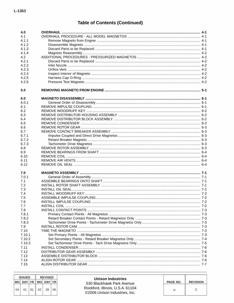
0.0 INTRODUCTION ......................................................................................................................................... 0-10.1 COPYRIGHT STATEMENT.......................................................................................................................... 0-10.2 HOW TO USE THIS MANUAL ..................................................................................................................... 0-10.3 RELEVANT PUBLICATIONS ....................................................................................................................... 0-20.4 SYSTEM OVERVIEW .................................................................................................................................. 0-2
1.0 TECHNICAL REFERENCE ......................................................................................................................... 1-11.1 GENERAL .................................................................................................................................................... 1-11.2 THEORY OF OPERATION .......................................................................................................................... 1-11.2.1 Lag Angle - Impulse Coupled Magnetos ............................................................................................. 1-11.2.2 Lag Angle - Retard Breaker Magnetos ................................................................................................ 1-11.2.3 Rotation ................................................................................................................................................ 1-11.3 MAGNETO PART NUMBERING .................................................................................................................. 1-11.4 MAGNETO SERIAL NUMBERS .................................................................................................................. 1-2
2.0 TOOLS REQUIRED ..................................................................................................................................... 2-1
3.0 MAINTENANCE .......................................................................................................................................... 3-13.1 MAINTENANCE SCHEDULE ...................................................................................................................... 3-13.1.1 100-Hour Inspection ............................................................................................................................. 3-13.1.2 500-Hour Inspection - Direct Drive Magnetos ..................................................................................... 3-13.1.3 500-Hour Inspection - Impulse Coupled Magnetos ............................................................................. 3-13.1.4 500-Hour Inspection - Retard Breaker Magnetos ................................................................................ 3-13.1.5 Additional 500-Hour Inspection Procedures for Pressurized Magnetos ............................................. 3-13.1.6 500-Hour Inspection - Tachometer Drive Magnetos ............................................................................ 3-13.1.7 Operational Check - All Magnetos ....................................................................................................... 3-13.2 100-HOUR INSPECTION ..................................................................................................................... 3-13.2.1 Adjust Timing to Engine ....................................................................................................................... 3-13.2.2 Inspect Wiring Connections and Condition ......................................................................................... 3-23.2.3 Inspect Vent Holes (Non-Pressurized Magnetos) ................................................................................ 3-23.2.4 Inspect P-Lead Attachment .................................................................................................................. 3-23.2.5 Inspect Switch Wire (Retard Breaker Magnetos Only) ........................................................................ 3-23.2.6 Inspect Tachometer Drive Contact Wire (Tach Drive Magnetos Only) ................................................ 3-23.2.7 Inspect Turbo Filter (Pressurized Magnetos Only) .............................................................................. 3-23.2.8 Inspect Inlet Nozzle (Pressurized Magnetos Only) ............................................................................. 3-23.2.9 Inspect Orifice Vent (Pressurized Magnetos Only) .............................................................................. 3-33.3 500-HOUR INSPECTION ............................................................................................................................ 3-33.3.1 Disassembly and Cleaning ................................................................................................................... 3-33.3.2 Inspect Ball Bearing Assembly ............................................................................................................ 3-33.3.3 Inspect Rotor ........................................................................................................................................ 3-33.3.4 Inspect Impulse Coupling (Impulse Coupled Magnetos Only) ............................................................ 3-33.3.5 Inspect Coil ........................................................................................................................................... 3-53.3.6 Inspect Contact Points ......................................................................................................................... 3-53.3.7 Inspect Condenser ............................................................................................................................... 3-63.3.8 Inspect Distributor Block Assembly ...................................................................................................... 3-73.3.9 Inspect Carbon Brush .......................................................................................................................... 3-73.3.10 Inspect for Structural Damage ............................................................................................................. 3-83.4 ADDITIONAL 500-HOUR PROCEDURES FOR PRESSURIZED MAGNETOS......................................... 3-83.4.1 Inlet Nozzle ........................................................................................................................................... 3-83.4.2 Orifice Vent ........................................................................................................................................... 3-83.4.3 Turbo Filter ............................................................................................................................................ 3-83.4.4 Gaskets ................................................................................................................................................. 3-83.4.5 O-Ring ................................................................................................................................................... 3-8
iii
L-1363
Unison Industries530 Blackhawk Park Avenue
Rockford, Illinois, U.S.A. 61104©2006 Unison Industries, Inc.
ISSUED
MO DAY YR
04 01 91
REVISED
MO DAY YR
02 28 06
PAGE NO. REVISION
C
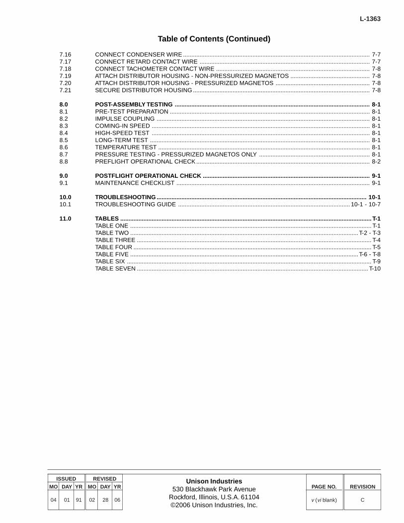
Table of Contents (Continued)
4.0 OVERHAUL ................................................................................................................................................. 4-14.1 OVERHAUL PROCEDURE - ALL MODEL MAGNETOS ............................................................................ 4-14.1.1 Remove Magneto from Engine ............................................................................................................ 4-14.1.2 Disassemble Magneto .......................................................................................................................... 4-14.1.3 Discard Parts to be Replaced .............................................................................................................. 4-14.1.4 Magneto Reassembly ........................................................................................................................... 4-24.2 ADDITIONAL PROCEDURES - PRESSURIZED MAGNETOS .................................................................. 4-24.2.1 Discard Parts to be Replaced .............................................................................................................. 4-24.2.2 Inlet Nozzle ........................................................................................................................................... 4-24.2.3 Orifice Vent. .......................................................................................................................................... 4-24.2.4 Inspect Interior of Magneto .................................................................................................................. 4-24.2.5 Harness Cap O-Ring ............................................................................................................................ 4-24.2.6 Pressure Test Magneto ......................................................................................................................... 4-2
5.0 REMOVING MAGNETO FROM ENGINE .................................................................................................... 5-1
6.0 MAGNETO DISASSEMBLY ........................................................................................................................ 6-16.0.1 General Order of Disassembly ............................................................................................................. 6-16.1 REMOVE IMPULSE COUPLING ................................................................................................................. 6-16.2 REMOVE WOODRUFF KEY ....................................................................................................................... 6-26.3 REMOVE DISTRIBUTOR HOUSING ASSEMBLY ...................................................................................... 6-26.4 REMOVE DISTRIBUTOR BLOCK ASSEMBLY ........................................................................................... 6-26.5 REMOVE CONDENSER ............................................................................................................................. 6-26.6 REMOVE ROTOR GEAR ............................................................................................................................. 6-36.7 REMOVE CONTACT BREAKER ASSEMBLY ............................................................................................. 6-36.7.1 Impulse Coupled and Direct Drive Magnetos ...................................................................................... 6-36.7.2 Retard Breaker Magneto ...................................................................................................................... 6-36.7.3 Tachometer Drive Magnetos ................................................................................................................ 6-36.8 REMOVE ROTOR ASSEMBLY .................................................................................................................... 6-36.9 REMOVE BEARINGS FROM SHAFT ......................................................................................................... 6-46.10 REMOVE COIL ............................................................................................................................................ 6-46.11 REMOVE AIR VENTS .................................................................................................................................. 6-46.12 REMOVE OIL SEAL .................................................................................................................................... 6-4
7.0 MAGNETO ASSEMBLY .............................................................................................................................. 7-17.0.1 General Order of Assembly .................................................................................................................. 7-17.1 ASSEMBLE BEARINGS ONTO SHAFT...................................................................................................... 7-17.2 INSTALL ROTOR SHAFT ASSEMBLY ........................................................................................................ 7-17.3 INSTALL OIL SEAL ...................................................................................................................................... 7-27.4 INSTALL WOODRUFF KEY......................................................................................................................... 7-27.5 ASSEMBLE IMPULSE COUPLING ............................................................................................................. 7-27.6 INSTALL IMPULSE COUPLING .................................................................................................................. 7-27.7 INSTALL COIL ............................................................................................................................................. 7-27.8 INSTALL CONTACT POINTS ...................................................................................................................... 7-37.8.1 Primary Contact Points - All Magnetos ................................................................................................ 7-37.8.2 Retard Breaker Contact Points - Retard Magnetos Only .................................................................... 7-37.8.3 Tachometer Drive Points - Tachometer Drive Magnetos Only ............................................................. 7-37.9 INSTALL ROTOR CAM ................................................................................................................................ 7-37.10 TIME THE MAGNETO ................................................................................................................................. 7-37.10.1 Set Primary Points - All Magnetos ....................................................................................................... 7-37.10.2 Set Secondary Points - Retard Breaker Magnetos Only ..................................................................... 7-47.10.3 Set Tachometer Drive Points - Tach Drive Magnetos Only .................................................................. 7-57.11 INSTALL CONDENSER ............................................................................................................................... 7-67.12 DISTRIBUTOR GEAR ASSEMBLY ............................................................................................................. 7-67.13 ASSEMBLE DISTRIBUTOR BLOCK ........................................................................................................... 7-67.14 ALIGN ROTOR GEAR ................................................................................................................................. 7-67.15 ALIGN DISTRIBUTOR GEAR...................................................................................................................... 7-7
iv
Unison Industries530 Blackhawk Park Avenue
Rockford, Illinois, U.S.A. 61104©2006 Unison Industries, Inc.
ISSUED
MO DAY YR
04 01 91
REVISED
MO DAY YR
02 28 06
PAGE NO. REVISION
C
L-1363
Table of Contents (Continued)
7.16 CONNECT CONDENSER WIRE ................................................................................................................. 7-77.17 CONNECT RETARD CONTACT WIRE ....................................................................................................... 7-77.18 CONNECT TACHOMETER CONTACT WIRE ............................................................................................. 7-87.19 ATTACH DISTRIBUTOR HOUSING - NON-PRESSURIZED MAGNETOS ................................................ 7-87.20 ATTACH DISTRIBUTOR HOUSING - PRESSURIZED MAGNETOS ......................................................... 7-87.21 SECURE DISTRIBUTOR HOUSING ........................................................................................................... 7-8
8.0 POST-ASSEMBLY TESTING ...................................................................................................................... 8-18.1 PRE-TEST PREPARATION ......................................................................................................................... 8-18.2 IMPULSE COUPLING ................................................................................................................................. 8-18.3 COMING-IN SPEED .................................................................................................................................... 8-18.4 HIGH-SPEED TEST .................................................................................................................................... 8-18.5 LONG-TERM TEST ..................................................................................................................................... 8-18.6 TEMPERATURE TEST ................................................................................................................................ 8-18.7 PRESSURE TESTING - PRESSURIZED MAGNETOS ONLY ................................................................... 8-18.8 PREFLIGHT OPERATIONAL CHECK ......................................................................................................... 8-2
9.0 POSTFLIGHT OPERATIONAL CHECK ..................................................................................................... 9-19.1 MAINTENANCE CHECKLIST ..................................................................................................................... 9-1
10.0 TROUBLESHOOTING ............................................................................................................................... 10-110.1 TROUBLESHOOTING GUIDE ........................................................................................................ 10-1 - 10-7
11.0 TABLES ........................................................................................................................................................ T-1TABLE ONE .................................................................................................................................................. T-1TABLE TWO ..........................................................................................................................................T-2 - T-3TABLE THREE .............................................................................................................................................. T-4TABLE FOUR ................................................................................................................................................ T-5TABLE FIVE ..........................................................................................................................................T-6 - T-8TABLE SIX .................................................................................................................................................... T-9TABLE SEVEN ............................................................................................................................................ T-10
v (vi blank)

THIS PAGE LEFT BLANK INTENTIONALLY.

Unison Industries530 Blackhawk Park Avenue
Rockford, Illinois, U.S.A. 61104©2006 Unison Industries, Inc.
ISSUED
MO DAY YR
04 01 91
REVISED
MO DAY YR
02 28 06
PAGE NO. REVISION
C
L-1363
0-1
Slick parts are produced and inspected under rigorousprocedures to insure airworthiness and suitability in Slickmagnetos. Parts purchased from sources other than UnisonIndustries, even though outwardly identical in appearance maynot have had the required tests and inspections performed,may be different in fabrication techniques and materials, andmay be dangerous when installed in a Slick magneto.Salvaged magneto parts, reworked parts obtained from non-Unison approved sources, or parts the service history of whichis unknown or cannot be authenticated, may have beensubjected to unacceptable stresses or temperatures, or haveother hidden damage, not discernible through routine visualor usual nondestructive testing techniques. This may renderservice work with this par t, even though originallymanufactured by Unison Industries, unsuitable or unsafe foruse in a Slick magneto. Slick expressly disclaims anyresponsibility for malfunctions, failures, damage or injurycaused by use of non-Unison approved parts.
Slick magnetos are engineered so that mechanical parts wearat a balanced rate. Consistent and complimentary wearpatterns establish the recommended maintenance intervalsdefined in Unison service literature, therefore used, serviceworn parts should never be used to troubleshoot or repair amagneto, nor should original parts be replaced by usedservice worn parts on magnetos being returned to service.Further, non-Unison manufactured parts may wear at unevenand different rates than original Unison manufactured parts,making Unison service literature an inappropriate guide toproper maintenance. Parts not manufactured by UnisonIndustries, even if FAA/PMA Approved may not fit or operatelike original Unison manufactured parts. FAA testing of PMAparts does not require operation on an engine or flight testsand does not require the test duration to exceed themaintenance intervals called out in Unison literature. Forthese reasons, used service worn parts or par ts notmanufactured by Slick may adversely affect magneto reliabilityin ways not anticipated by Unison Industries and its serviceliterature.
The information in this manual is divided into 10 sections.Section One provides basic technical reference on the designand operation of Slick Magnetos. Section Two illustrates toolsneeded to correctly perform inspection and maintenance.
Detailed instructions for removing the magnetos from theengine, magneto disassembly and magneto reassembly arecontained in Sections Five, Six and Seven, respectively.
Maintenance and Overhaul schedules and procedures aredetailed in Sections Three and Four, respectively. Theinstructions in Sections Three and Four refer to proceduresoutlined in the Magneto Disassembly (Section Six) andMagneto Assembly (Section Seven) portions of this manual.It is recommended that this entire manual be thoroughly readbefore beginning any inspection or maintenance procedure.
After any inspection or maintenance is done on SlickMagnetos, the testing procedures in Section Eight should beperformed completely.
0.0 INTRODUCTION
0.1 COPYRIGHT STATEMENT
All rights reserved. This manual is produced exclusively foruse with Unison Industries Magnetos and/or IgnitionHarnesses. It may not, in whole or in part, be copied,photocopied, reproduced, translated or reduced to anyelectronic medium or machine readable form without priorconsent, in writing, from Unison Industries.
WARNING: IMPROPER OR UNAUTHORIZEDAPPLICATIONS OF THE INFORMATION CONTAINEDIN THIS MANUAL MAY RESULT IN LOSSES ORDAMAGES TO THE USER.
The accuracy and applicability of this manual has not beenverified for any assembly, component or par t notmanufactured by Unison Industries. Any use of thismanual for other than its intended purpose or forperforming any installation, maintenance, replacement,adjustment, inspection or overhaul of any assembly,component or part not manufactured by Unison Industriesis not approved, endorsed or sanctioned by UnisonIndustries.
No liability will be assumed by Unison Industries for actual,consequential or other types of damages directly or indi-rectly resulting from the unauthorized use of this manualfor other than its stated purposes.
When performing installation, maintenance, replacement,adjustment, inspection or overhaul of any Unisonassembly, component or part, it is imperative that the latestrevision of the appropriate Unison manual or productsupport document be referenced. Contact Unison to besure you have the latest manual or support documentrevision before performing any work.
All reasonable attempts were made to make this manualas complete and accurate as possible. It you have anyquestions, comments, corrections or require clarificationof any information contained herein, please call or writeUnison Industr ies, Technical Publications, 7575Baymeadows Way, Jacksonville, FL 32256, Phone904-739-4132 (Fax 904-739-4006), or [email protected].
0.2 HOW TO USE THIS MANUAL
The procedures outlined in this manual are generalized forall models of 4300/6300 Series Slick Magnetos, using onlygenuine Unison manufactured parts. This manual must notbe used to maintain or overhaul a Slick Magneto that con-tains parts not manufactured by Unison Industries. Specificpart numbers are detailed in the Tables located after the maintext.
Use only genuine Unison manufactured parts obtained fromUnison Industries Approved sources.
L-1363
Unison Industries530 Blackhawk Park Avenue
Rockford, Illinois, U.S.A. 61104©2006 Unison Industries, Inc.
ISSUED
MO DAY YR
04 01 91
REVISED
MO DAY YR
02 28 06
PAGE NO. REVISION
C
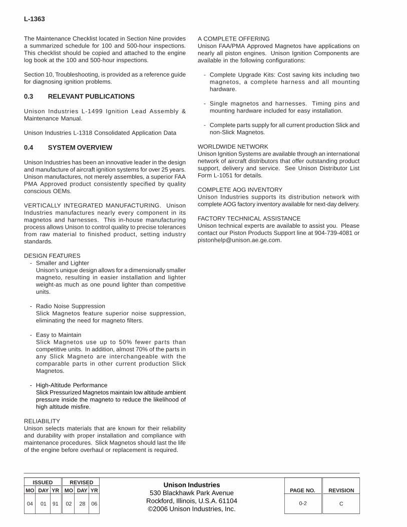
The Maintenance Checklist located in Section Nine providesa summarized schedule for 100 and 500-hour inspections.This checklist should be copied and attached to the enginelog book at the 100 and 500-hour inspections.
Section 10, Troubleshooting, is provided as a reference guidefor diagnosing ignition problems.
0.3 RELEVANT PUBLICATIONS
Unison Industr ies L-1499 Ignition Lead Assembly &Maintenance Manual.
Unison Industries L-1318 Consolidated Application Data
0.4 SYSTEM OVERVIEW
Unison Industries has been an innovative leader in the designand manufacture of aircraft ignition systems for over 25 years.Unison manufactures, not merely assembles, a superior FAAPMA Approved product consistently specified by qualityconscious OEMs.
VERTICALLY INTEGRATED MANUFACTURING. UnisonIndustries manufactures nearly every component in itsmagnetos and harnesses. This in-house manufacturingprocess allows Unison to control quality to precise tolerancesfrom raw material to finished product, setting industrystandards.
DESIGN FEATURES- Smaller and Lighter
Unison’s unique design allows for a dimensionally smallermagneto, resulting in easier installation and lighterweight-as much as one pound lighter than competitiveunits.
- Radio Noise SuppressionSlick Magnetos feature superior noise suppression,eliminating the need for magneto filters.
- Easy to MaintainSlick Magnetos use up to 50% fewer par ts thancompetitive units. In addition, almost 70% of the parts inany Slick Magneto are interchangeable with thecomparable parts in other current production SlickMagnetos.
- High-Altitude PerformanceSlick Pressurized Magnetos maintain low altitude ambientpressure inside the magneto to reduce the likelihood ofhigh altitude misfire.
RELIABILITYUnison selects materials that are known for their reliabilityand durability with proper installation and compliance withmaintenance procedures. Slick Magnetos should last the lifeof the engine before overhaul or replacement is required.
0-2
A COMPLETE OFFERINGUnison FAA/PMA Approved Magnetos have applications onnearly all piston engines. Unison Ignition Components areavailable in the following configurations:
- Complete Upgrade Kits: Cost saving kits including twomagnetos, a complete harness and all mountinghardware.
- Single magnetos and harnesses. Timing pins andmounting hardware included for easy installation.
- Complete parts supply for all current production Slick andnon-Slick Magnetos.
WORLDWIDE NETWORKUnison Ignition Systems are available through an internationalnetwork of aircraft distributors that offer outstanding productsupport, delivery and service. See Unison Distributor ListForm L-1051 for details.
COMPLETE AOG INVENTORYUnison Industries supports its distribution network withcomplete AOG factory inventory available for next-day delivery.
FACTORY TECHNICAL ASSISTANCEUnison technical experts are available to assist you. Pleasecontact our Piston Products Support line at 904-739-4081 [email protected].
Unison Industries530 Blackhawk Park Avenue
Rockford, Illinois, U.S.A. 61104©2006 Unison Industries, Inc.
ISSUED
MO DAY YR
04 01 91
REVISED
MO DAY YR
02 28 06
PAGE NO. REVISION
C
L-1363
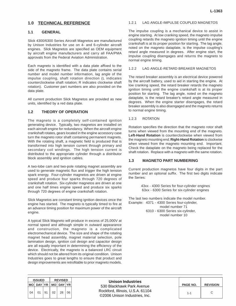
1.2.1 LAG ANGLE-IMPULSE COUPLED MAGNETOS
The impulse coupling is a mechanical device to assist inengine starting. At low cranking speed, the magneto impulsecoupling retards the magneto ignition timing until the enginecrankshaft is at its proper position for starting. The lag angle,noted on the magneto dataplate, is the impulse coupling’sretard angle measured in degrees. After engine start, theimpulse coupling disengages and returns the magneto tonormal engine timing.
1.2.2 LAG ANGLE-RETARD BREAKER MAGNETOS
The retard breaker assembly is an electrical device poweredby the aircraft battery, used to aid in starting the engine. Atlow cranking speed, the retard breaker retards the magnetoignition timing until the engine crankshaft is at its properposition for starting. The lag angle, noted on the magnetodataplate, is the retard breaker’s retard angle measured indegrees. When the engine starter disengages, the retardbreaker assembly is also disengaged and the magneto returnsto normal engine timing.
1.2.3 ROTATION
Rotation specifies the direction that the magneto rotor shaftturns when viewed from the mounting end of the magneto.Left-Hand Rotation is counterclockwise when viewed fromthe magneto mounting end; Right-Hand Rotation is clockwisewhen viewed from the magneto mounting end. Important.Check the dataplate on the magneto being replaced for theshaft rotation. Replace with a magneto with the same rotation.
1.3 MAGNETO PART NUMBERING
Current production magnetos have four digits in the partnumber and an optional suffix. The first two digits indicatethe Series:
43xx - 4300 Series for four-cylinder engines63xx - 6300 Series for six-cylinder engines
The last two numbers indicate the model number.Example: 4371 - 4300 Series four-cylinder,
model number 716310 - 6300 Series six-cylinder,
model number 10
1.0 TECHNICAL REFERENCE
1.1 GENERAL
Slick 4300/6300 Series Aircraft Magnetos are manufacturedby Unison Industries for use on 4- and 6-cylinder aircraftengines. Slick Magnetos are specified as OEM equipmentby aircraft engine manufacturers and carry all FAA/PMAapprovals from the Federal Aviation Administration.
Each magneto is identified with a data plate affixed to theside of the magneto frame. The data plate contains serialnumber and model number information, lag angle of theimpulse coupling, shaft rotation direction (L indicatescounterclockwise shaft rotation; R indicates clockwise shaftrotation). Customer part numbers are also provided on thedata plate.
All current production Slick Magnetos are provided as newunits, identified by a red data plate.
1.2 THEORY OF OPERATION
The magneto is a completely self-contained ignitiongenerating device. Typically, two magnetos are installed oneach aircraft engine for redundancy. When the aircraft enginecrankshaft rotates, gears located in the engine accessory caseturn the magneto rotor shaft containing permanent magnets.With the rotating shaft, a magnetic field is produced that istransformed into high tension current through primary andsecondary coil windings. The high tension current isdistributed to the appropriate cylinder through a distributorblock assembly and ignition cables.
A two-lobe cam and two-pole rotating magnet assembly areused to generate magnetic flux and trigger the high tensionspark energy. Four-cylinder magnetos are driven at enginespeed and produce four sparks through 720 degrees ofcrankshaft rotation. Six-cylinder magnetos are driven at oneand one half times engine speed and produce six sparksthrough 720 degrees of engine crankshaft rotation.
Slick Magnetos are constant timing ignition devices once theengine has started. The magneto is typically timed to fire atan advance timing position for maximum power of the aircraftengine.
A typical Slick Magneto will produce in excess of 25,000V atnormal speed and although simple in outward appearanceand construction, the magneto is a complicatedelectromechanical device. The size and shape of the rotatingmagnet head assembly, magnet material selection, polelamination design, ignition coil design and capacitor designare all equally important in determining the efficiency of thedevice. Electrically, the magneto is a balanced LRC circuitwhich should not be altered from its original condition. UnisonIndustries goes to great lengths to ensure that product anddesign improvements are retrofitable to prior magneto models.
1-1
L-1363
Unison Industries530 Blackhawk Park Avenue
Rockford, Illinois, U.S.A. 61104©2006 Unison Industries, Inc.
ISSUED
MO DAY YR
04 01 91
REVISED
MO DAY YR
02 28 06
PAGE NO. REVISION
C1-2
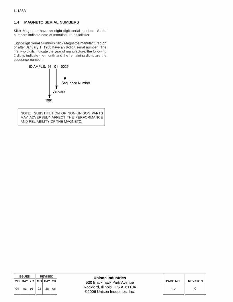
1.4 MAGNETO SERIAL NUMBERS
Slick Magnetos have an eight-digit serial number. Serialnumbers indicate date of manufacture as follows:
Eight-Digit Serial Numbers Slick Magnetos manufactured onor after January 1, 1988 have an 8-digit serial number. Thefirst two digits indicate the year of manufacture, the following2 digits indicate the month and the remaining digits are thesequence number.
NOTE: SUBSTITUTION OF NON-UNISON PARTSMAY ADVERSELY AFFECT THE PERFORMANCEAND RELIABILITY OF THE MAGNETO.
EXAMPLE: 91 01 0025
Sequence Number
January
1991

Unison Industries530 Blackhawk Park Avenue
Rockford, Illinois, U.S.A. 61104©2006 Unison Industries, Inc.
ISSUED
MO DAY YR
04 01 91
REVISED
MO DAY YR
02 28 06
PAGE NO. REVISION
C
L-1363
T125 ASSEMBLY FIXTURE
T509 SPACER
T152 SPACER
T119 BUSHING, ADAPTER PLATE
T117 BASE ADAPTER PLATE
T106 PULLER
T102 ROTORAND FRAMEASSEMBLINGPLUG
T123 TIMING PLUGT122 WEDGE EXTRACTOR
T121 BEARING PULLER (2 HALVES)T118 TIMING PIN
T150 “E” GAP GAUGE
T151, T153 CAM AND ROTOR SET
T101 BEARINGASSEMBLING PLUG
T103 OIL SEAL ASSEMBLING PLUG
T155 RIVET GAUGE
2-1
2.0 TOOLS REQUIRED
T-100 Assembly and Timing Kit includes:
P/N Description QtyT101 Bearing Assembling Plug 1T102 Rotor and Frame Assembling Plug 1T103 Oil Seal Assembling Plug 1T106 Puller 1T117 Base Adapter Plate 1T118 Timing Pin 1T119 Bushing, Adapter Plate 1T121 Bearing Puller (2 Halves) 1T122 Wedge Extractor 1T123 Timing Plug 1T125 Assembly Fixture 1T150 “E” Gap Gauge 1T151 Cam and Rotor Set 1T152 Spacer 1T153 Alternate Cam and Rotor Set 1T155 Rivet Gauge 1T509 Spacer (included with T125) 1

THIS PAGE LEFT BLANK INTENTIONALLY.
Unison Industries530 Blackhawk Park Avenue
Rockford, Illinois, U.S.A. 61104©2006 Unison Industries, Inc.
ISSUED
MO DAY YR
04 01 91
REVISED
MO DAY YR
02 28 06
PAGE NO. REVISION
C
L-1363
3-1
3.0 MAINTENANCE
3.1 MAINTENANCE SCHEDULE
3.1.1 100-HOUR INSPECTION
A. Adjust timing to engineB. Inspections
1. Wiring connections and conditions2. Vent holes (non-pressurized magnetos)3. P-lead attachment4. Retard breaker switch wire (retard breaker
magnetos)5. Inspect tachometer drive wire (tachometer drive
magnetos6. Turbo filter used with pressurized magnetos7. Inlet nozzle (pressurized magnetos)8. Orifice vent (pressurized magnetos)9. Pressure check
3.1.2 500-HOUR INSPECTION - DIRECT DRIVEMAGNETOS
A. CleaningB. Ball bearing assemblyC. CoilD. Contact pointsE. CondenserF. Carbon brushG. Lubrication
3.1.3 500-HOUR INSPECTION - IMPULSE COUPLEDMAGNETOS
A. CleaningB. Ball bearing assemblyC. Impulse couplingD. CoilE. Contact pointsF. CondenserG. Carbon BrushH. Lubrication
3.1.4 500-HOUR INSPECTION - RETARD BREAKERMAGNETOS
A. CleaningB. Ball bearing assemblyC. Impulse couplingD. CoilE. Primary contact pointsF. Retard breaker contact pointsG. CondenserH. Carbon brushI. Lubrication
3.1.5 ADDITIONAL 500-HOUR INSPECTIONPROCEDURES FOR PRESSURIZED MAGNETOS
A. Inlet nozzle, orifice vent and turbo filterB. Inspect inside of magneto for turbocharger
contaminantsC. Frame gasket and screw gasketD. Harness cap O-RingE. Pressure testing
3.1.6 500-HOUR INSPECTION - TACHOMETER DRIVEMAGNETOS ONLY
A. CleaningB. Ball bearing assemblyC. Impulse couplingD. CoilE. Primary contact pointsF. Tachometer drive pointsG. CondenserH. Carbon brushI. Lubrication
3.1.7 OPERATIONAL CHECK - ALL MAGNETOS
A. Before flight or after routine maintenance observeengine operation while running on both magnetosand left or right magneto individually. Both magnetosshould demonstrate normal operation and engineshould operate within parameters outlined in theengine manufacturer’s operating manual. DO NOTFLY AIRCRAFT IF MAGNETOS ARE NOTFUNCTIONING NORMALLY.
B. Postflight magneto operational check should beperformed after each flight. Observe engineoperation while running on both magnetos and leftor r ight individually. Both magnetos shoulddemonstrate normal operation and engine shouldoperate within the parameters outlined in the enginemanufacturer’s operating manual. DO NOT FLYAIRCRAFT IF MAGNETOS ARE NOTFUNCTIONING NORMALLY.
3.2 100-HOUR INSPECTION
The following maintenance procedures should be followedevery 100 hours of service or at annual inspection, whichevercomes first. Perform maintenance on each magneto.
3.2.1 ADJUST TIMING TO ENGINE
CAUTION: BE SURE IGNITION SWITCH IS IN“OFF” POSITION AND THE CONDENSER LEAD ISGROUNDED.
A. Turn the engine crankshaft in the normal directionof rotation until the No. 1 cylinder is in the full-advancefiring position, following engine manufacturer’sprocedure for timing of magnetos.
L-1363
Unison Industries530 Blackhawk Park Avenue
Rockford, Illinois, U.S.A. 61104©2006 Unison Industries, Inc.
ISSUED
MO DAY YR
04 01 91
REVISED
MO DAY YR
02 28 06
PAGE NO. REVISION
C3-2
3.2.2 INSPECT WIRING CONNECTIONS ANDCONDITIONS
Refer to Harness Maintenance Manual L-1177 for completewiring inspection instructions.
3.2.3 INSPECT VENT HOLES - NON-PRESSURIZEDMAGNETOS
Vent holes must be clean and clear of any obstruction. Correctas necessary.
3.2.4 INSPECT P-LEAD ATTACHMENT
The P-lead connects the magneto primary circuit to theairframe ignition switch. If the P-lead is disconnected, themagneto will be “ON” and will fire the spark plug if the propelleris rotated. Possible fatal injury can result. Confirm that theP-lead is securely attached to the condenser stud. TorqueP-lead nut to 13-15 in-lbs.
CAUTION: IF 13-15 IN-LBS TORQUE LIMIT ISEXCEEDED, CONDENSER PERFORMANCE MAYBECOME INTERMITTENT OR TOTALLYINOPERATIVE. REPLACE CONDENSER IF TORQUELIMIT IS EXCEEDED, FOLLOWING INSTRUCTIONSIN SECTIONS 6.5 AND 7.12 OF THIS MANUAL.
Follow airframe manufacturer’s recommendations to ensurethe ignition switch and P-lead are operating properly.
3.2.5 INSPECT SWITCH WIRE - RETARD BREAKERMAGNETOS ONLY
The retard breaker lead connects the retard contact points tothe ignition vibrator. If this lead is disconnected the startingcircuit will become inoperative.
CAUTION: IF 13-15 IN-LBS TORQUE LIMIT ISEXCEEDED, STARTING CIRCUIT MAY BECOMEINOPERATIVE.
Follow the airframe manufacturer’s recommendations toensure that the ignition switch and retard breaker lead areoperating properly.
3.2.6 INSPECT TACHOMETER DRIVE CONTACT WIRE- TACHOMETER DRIVE MAGNETOS ONLY
The tachometer lead connects the tachometer drive contactpoints to the tachometer. If this lead is disconnected, thetachometer will become inoperative. Follow the airframemanufacturer’s recommendations to ensure that thetachometer drive lead is attached properly.
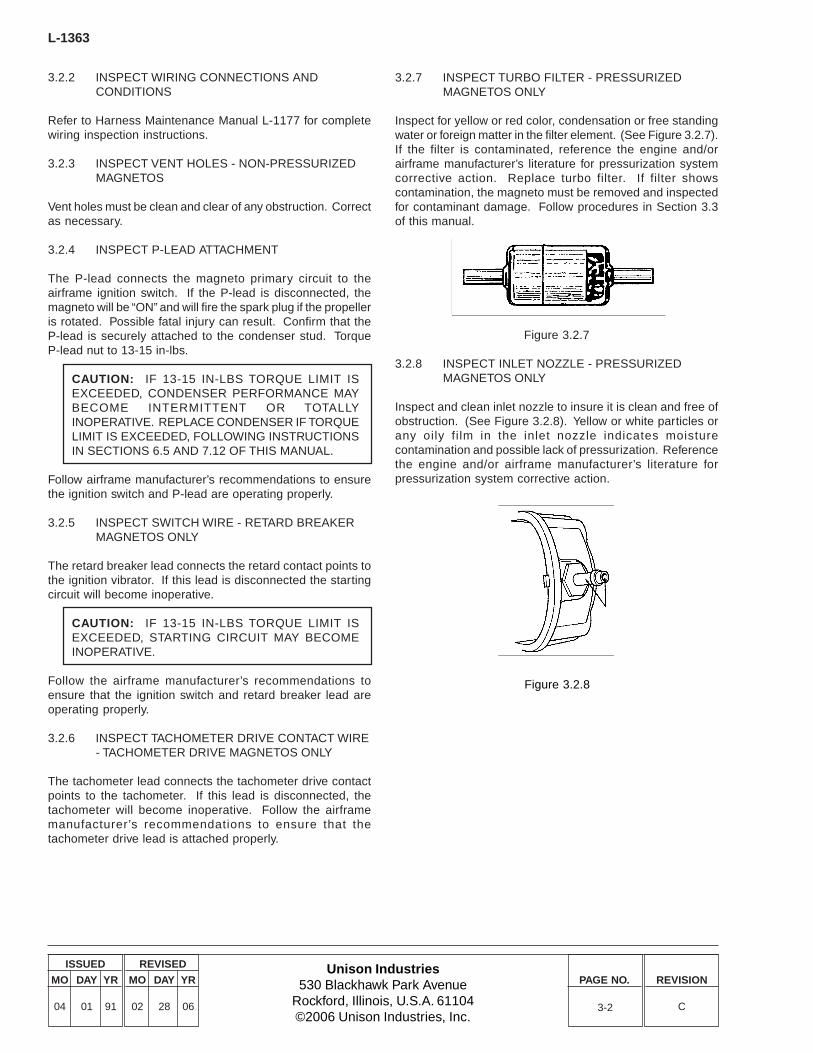
3.2.7 INSPECT TURBO FILTER - PRESSURIZEDMAGNETOS ONLY
Inspect for yellow or red color, condensation or free standingwater or foreign matter in the filter element. (See Figure 3.2.7).If the filter is contaminated, reference the engine and/orairframe manufacturer’s literature for pressurization systemcorrective action. Replace turbo filter. If filter showscontamination, the magneto must be removed and inspectedfor contaminant damage. Follow procedures in Section 3.3of this manual.
Figure 3.2.7
3.2.8 INSPECT INLET NOZZLE - PRESSURIZEDMAGNETOS ONLY
Inspect and clean inlet nozzle to insure it is clean and free ofobstruction. (See Figure 3.2.8). Yellow or white particles orany oily fi lm in the inlet nozzle indicates moisturecontamination and possible lack of pressurization. Referencethe engine and/or airframe manufacturer’s literature forpressurization system corrective action.
Figure 3.2.8
Unison Industries530 Blackhawk Park Avenue
Rockford, Illinois, U.S.A. 61104©2006 Unison Industries, Inc.
ISSUED
MO DAY YR
04 01 91
REVISED
MO DAY YR
02 28 06
PAGE NO. REVISION
C
L-1363
3-3
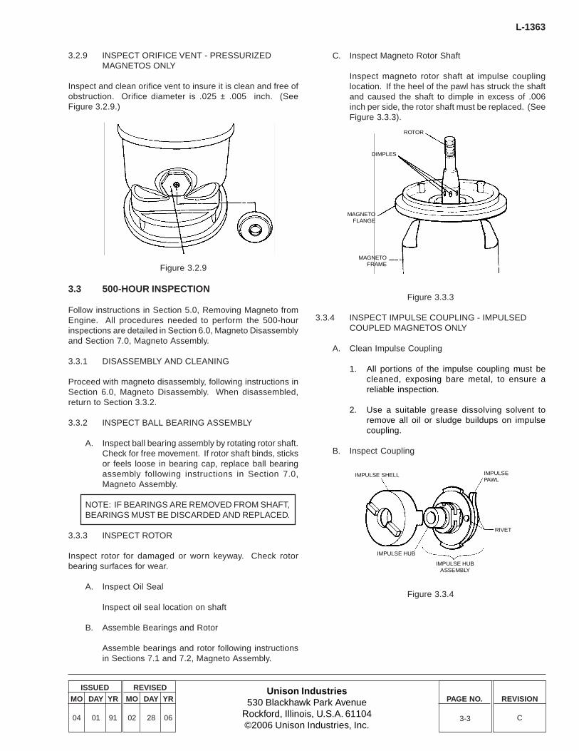
3.2.9 INSPECT ORIFICE VENT - PRESSURIZEDMAGNETOS ONLY
Inspect and clean orifice vent to insure it is clean and free ofobstruction. Orifice diameter is .025 ± .005 inch. (SeeFigure 3.2.9.)
Figure 3.2.9
3.3 500-HOUR INSPECTION
Follow instructions in Section 5.0, Removing Magneto fromEngine. All procedures needed to perform the 500-hourinspections are detailed in Section 6.0, Magneto Disassemblyand Section 7.0, Magneto Assembly.
3.3.1 DISASSEMBLY AND CLEANING
Proceed with magneto disassembly, following instructions inSection 6.0, Magneto Disassembly. When disassembled,return to Section 3.3.2.
3.3.2 INSPECT BALL BEARING ASSEMBLY
A. Inspect ball bearing assembly by rotating rotor shaft.Check for free movement. If rotor shaft binds, sticksor feels loose in bearing cap, replace ball bearingassembly following instructions in Section 7.0,Magneto Assembly.
NOTE: IF BEARINGS ARE REMOVED FROM SHAFT,BEARINGS MUST BE DISCARDED AND REPLACED.
3.3.3 INSPECT ROTOR
Inspect rotor for damaged or worn keyway. Check rotorbearing surfaces for wear.
A. Inspect Oil Seal
Inspect oil seal location on shaft
B. Assemble Bearings and Rotor
Assemble bearings and rotor following instructionsin Sections 7.1 and 7.2, Magneto Assembly.
C. Inspect Magneto Rotor Shaft
Inspect magneto rotor shaft at impulse couplinglocation. If the heel of the pawl has struck the shaftand caused the shaft to dimple in excess of .006inch per side, the rotor shaft must be replaced. (SeeFigure 3.3.3).
Figure 3.3.3
3.3.4 INSPECT IMPULSE COUPLING - IMPULSEDCOUPLED MAGNETOS ONLY
A. Clean Impulse Coupling
1. All portions of the impulse coupling must becleaned, exposing bare metal, to ensure areliable inspection.
2. Use a suitable grease dissolving solvent toremove all oil or sludge buildups on impulsecoupling.
B. Inspect Coupling
ROTOR
DIMPLES
MAGNETOFLANGE
MAGNETOFRAME
IMPULSE SHELL
IMPULSE HUB
IMPULSE HUBASSEMBLY
RIVET
IMPULSEPAWL
Figure 3.3.4
L-1363
Unison Industries530 Blackhawk Park Avenue
Rockford, Illinois, U.S.A. 61104©2006 Unison Industries, Inc.
ISSUED
MO DAY YR
04 01 91
REVISED
MO DAY YR
02 28 06
PAGE NO. REVISION
C3-4
NOTE: IN MANY CASES, STRINGERS, INCLUSIONSAND HEAT CHECKS MAY APPEAR AS SURFACEDISCONTINUITIES ON IMPULSE COUPLINGCOMPONENTS. THESE CONDITIONS ARE NORMALAND GENERALLY DO NOT, BY THEMSELVES,REQUIRE IMPULSE COUPLING REPLACEMENT.
1. Using acceptable procedures, inspect theimpulse coupling shell for cracks, rust or signsof corrosion. None of these conditions areacceptable. Minor cleaning to remove surfacerust is acceptable. Replace impulse couplingas necessary.
2. Inspect the impulse coupling hub for cracks, rustor signs of corrosion. None of these conditionsare acceptable. Minor cleaning to removesurface rust is acceptable. Replace impulsecoupling as necessary.
3. Inspect the hub shaft and keyway fordeformation or damage. Replace impulsecoupling as necessary.
4. Inspect impulse coupling pawls. It the latchingend that contacts the stop pin in the magnetoframe is rounded, peened or excessively worn,replace the impulse coupling.
5. Inspect pawl retaining rivets. If the rivets areloose or show indications of movement, thenreplace the impulse coupling.
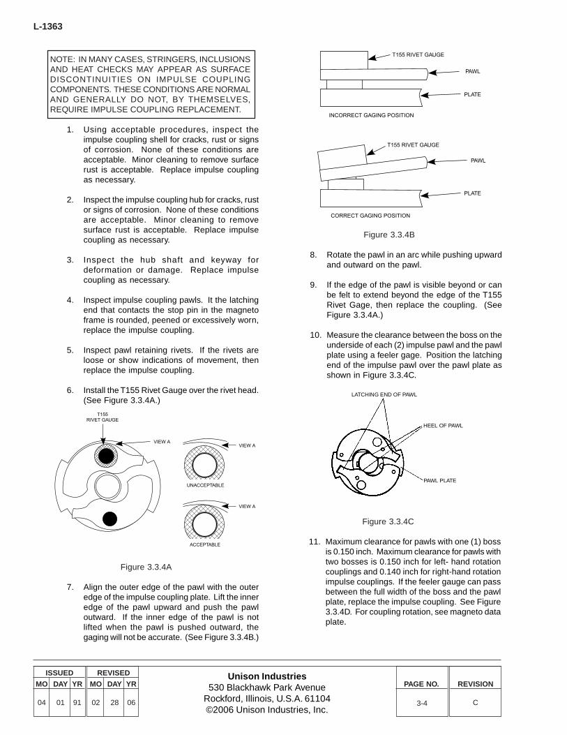
6. Install the T155 Rivet Gauge over the rivet head.(See Figure 3.3.4A.)
Figure 3.3.4B
8. Rotate the pawl in an arc while pushing upwardand outward on the pawl.
9. If the edge of the pawl is visible beyond or canbe felt to extend beyond the edge of the T155Rivet Gage, then replace the coupling. (SeeFigure 3.3.4A.)
10. Measure the clearance between the boss on theunderside of each (2) impulse pawl and the pawlplate using a feeler gage. Position the latchingend of the impulse pawl over the pawl plate asshown in Figure 3.3.4C.
T155RIVET GAUGE
VIEW AVIEW A
UNACCEPTABLE
ACCEPTABLE
VIEW A
T155 RIVET GAUGE
PAWL
PLATE
INCORRECT GAGING POSITION
T155 RIVET GAUGE
PAWL
PLATE
CORRECT GAGING POSITION
Figure 3.3.4A
7. Align the outer edge of the pawl with the outeredge of the impulse coupling plate. Lift the inneredge of the pawl upward and push the pawloutward. If the inner edge of the pawl is notlifted when the pawl is pushed outward, thegaging will not be accurate. (See Figure 3.3.4B.)
LATCHING END OF PAWL
HEEL OF PAWL
PAWL PLATE
Figure 3.3.4C
11. Maximum clearance for pawls with one (1) bossis 0.150 inch. Maximum clearance for pawls withtwo bosses is 0.150 inch for left- hand rotationcouplings and 0.140 inch for right-hand rotationimpulse couplings. If the feeler gauge can passbetween the full width of the boss and the pawlplate, replace the impulse coupling. See Figure3.3.4D. For coupling rotation, see magneto dataplate.
Unison Industries530 Blackhawk Park Avenue
Rockford, Illinois, U.S.A. 61104©2006 Unison Industries, Inc.
ISSUED
MO DAY YR
04 01 91
REVISED
MO DAY YR
02 28 06
PAGE NO. REVISION
C
L-1363
Figure 3.3.4D
C. Reassemble Impulse Coupling
1. Lubricate the pawl assembly with aircraft engineoil. Ensure that the pawls move freely.
2. Lubricate the hub and spring with aircraft engineoil.
3. Follow reassembly instructions, Section 7.5 ofthis manual.
D. Inspect Stop Pin
1. Inspect the stop pin for looseness, cracks orcorrosion. None of these conditions areacceptable. Replace magneto frame asnecessary. (See Figure 3.3.4E.)
IMPULSE PAWL
BOSS
FEELER GAGE
3-5
3.3.5 INSPECT COIL
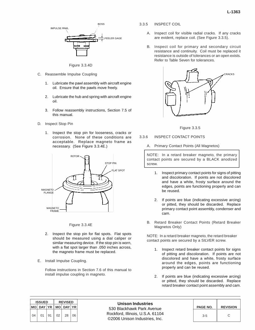
A. Inspect coil for visible radial cracks. If any cracksare evident, replace coil. (See Figure 3.3.5).
B. Inspect coil for primary and secondary circuitresistance and continuity. Coil must be replaced itresistance is outside of tolerances or an open exists.Refer to Table Seven for tolerances.
Figure 3.3.5
3.3.6 INSPECT CONTACT POINTS
A. Primary Contact Points (All Magnetos)
NOTE: In a retard breaker magneto, the primarycontact points are secured by a BLACK anodizedscrew.
1. Inspect primary contact points for signs of pittingand discoloration. If points are not discoloredand have a white, frosty surface around theedges, points are functioning properly and canbe reused.
2. If points are blue (indicating excessive arcing)or pitted, they should be discarded. Replaceprimary contact point assembly, condenser andcam.
B. Retard Breaker Contact Points (Retard BreakerMagnetos Only)
NOTE: In a retard breaker magneto, the retard breakercontact points are secured by a SILVER screw.
1. Inspect retard breaker contact points for signsof pitting and discoloration. If points are notdiscolored and have a white, frosty surfacearound the edges, points are functioningproperly and can be reused.
2. If points are blue (indicating excessive arcing)or pitted, they should be discarded. Replaceretard breaker contact point assembly and cam.
ROTOR
STOP PIN
FLAT SPOT
MAGNETOFLANGE
MAGNETOFRAME
CRACKS
Figure 3.3.4E
2. Inspect the stop pin for flat spots. Flat spotsshould be measured using a dial caliper orsimilar measuring device. If the stop pin is worn,with a flat spot larger than .050 inches across,the magneto frame must be replaced.
E. Install Impulse Coupling.
Follow instructions in Section 7.6 of this manual toinstall impulse coupling in magneto.

L-1363
Unison Industries530 Blackhawk Park Avenue
Rockford, Illinois, U.S.A. 61104©2006 Unison Industries, Inc.
ISSUED
MO DAY YR
04 01 91
REVISED
MO DAY YR
02 28 06
PAGE NO. REVISION
C3-6
C. Tachometer Drive Contact Points (Tachometer DriveMagnetos Only)
1. Inspect tachometer drive contact points for signsof pitting and discoloration. If points are notdiscolored and have a white, frosty surfacearound the edges, points are functioningproperly and can be reused.
2. If points are blue (indicating excessive arcing)or pitted, they should be discarded. Replacetachometer drive contact point assembly andcam.
3.3.7 INSPECT CONDENSER
A. Clean Condenser
1. If the external surfaces of the condenser aredirty, clean with light soapy water.
2. Rinse soapy water and dirt from condensersurfaces with clear water and pat dry beforereinstallation into the magneto housing.
B. Condenser Inspection
1. Inspect the condenser for signs of corrosion.This condition is cause for component rejection.(See Figure 3.3.7).
3. Inspect the condenser P-lead stud for twistingor “pulled” condition. Using a magnifying lens,examine the glass bead end seals of thecapacitor for broken glass or for glass separationfrom the retaining steel rings. Either of theseconditions is cause for component rejection.(See Figure 3.3.7A.)
Figure 3.3.7A
C. Test Capacitor.
Test the electrical properties of the capacitor usingthe GenRad Digibridge 1157 component analyzerand a megohmmeter, or equivalent test equipment.
1. Capacitance value should be measured at roomtemperature, and 1 khz frequency. The servicelimit of the capacitor is .315 to .385 microfarad.
2. Test the insulation resistance of the capacitorusing a megohmmeter. The resistancemeasured between the capacitor stud and shellshould be 50 Gigohms minimum at 135 VDC.
NOTE: NO FIELD REPAIRS OF THE CONDENSER AREAPPROVED. UNDER NO CIRCUMSTANCES SHOULDTHE CONDENSER LEAD BE RESOLDERED TO THECONDENSER STUD IF IT BECOMES DETACHED.SOLDERING THIS LEAD CAN RESULT IN ELECTRICALBREAKDOWN INSIDE THE CAPACITOR AND/OR LOSSOF HERMETIC INTEGRITY.
D. Install Condenser.
Install condenser following instructions in Section7.12 of this manual.
Figure 3.3.7
2. Inspect the condenser wire for chafing, frayedinsulation, or exposed wires that could contactframe. Replace as necessary.
NOTE: Current condensor design utilizes a D shapedinsulator to prevent damage from Over-Torquing ofP-lead stud.
Unison Industries530 Blackhawk Park Avenue
Rockford, Illinois, U.S.A. 61104©2006 Unison Industries, Inc.
ISSUED
MO DAY YR
04 01 91
REVISED
MO DAY YR
02 28 06
PAGE NO. REVISION
C
L-1363
3-7
3.3.8 INSPECT DISTRIBUTOR BLOCK ASSEMBLY
A. Clean block assembly.
1. Disassemble and clean the distributor blockbear ing bar using standard non-fi lming,nonconductive cleaner. Clean distributor gearwith soapy water and rinse with clear water.
CAUTION: DO NOT PUT CLEANER IN EITHERBRONZE OILITE BUSHING. THESE BUSHINGS AREIMPREGNATED AT THE FACTORY AND CLEANERWILL DRAW THE LUBRICANT OUT OF THE BUSHING.
2. Using a cotton swab or “Q-Tip”, clean allsurfaces free of dirt, oil, carbon dust and othercontaminants.
B. Inspect Distributor Block.
1. Visually inspect the block for cracks or otherphysical damage. Replace block assembly asnecessary.
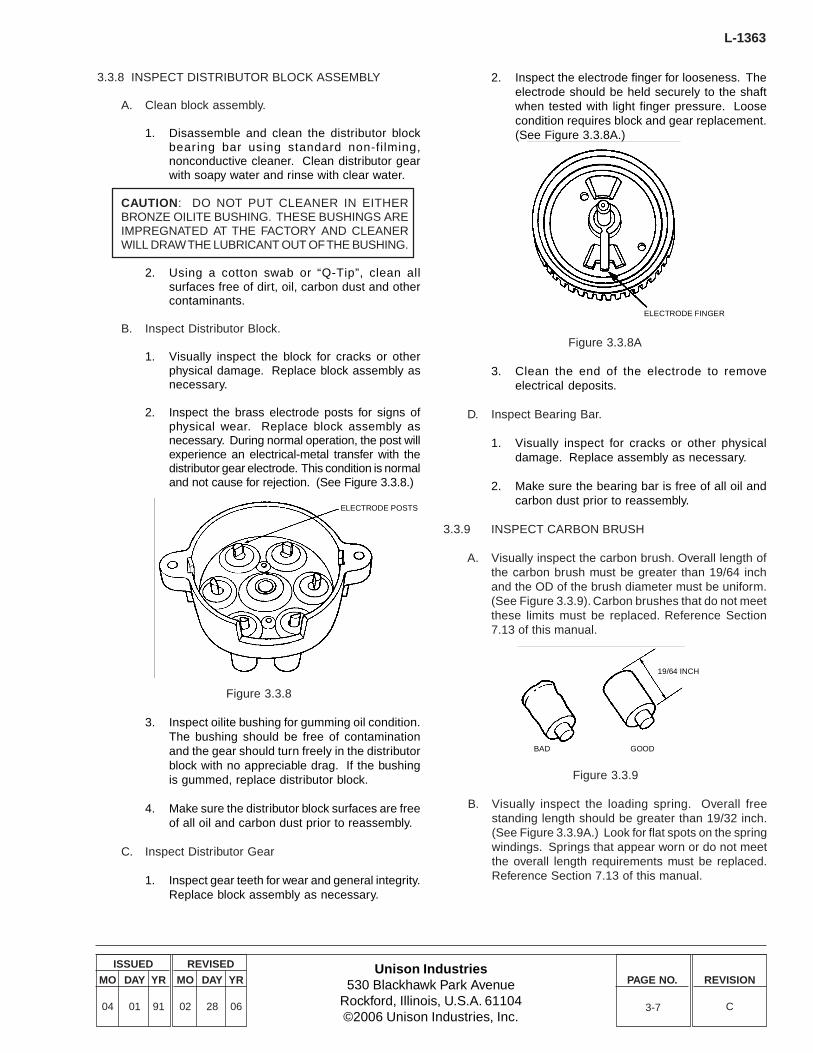
2. Inspect the brass electrode posts for signs ofphysical wear. Replace block assembly asnecessary. During normal operation, the post willexperience an electrical-metal transfer with thedistributor gear electrode. This condition is normaland not cause for rejection. (See Figure 3.3.8.)
Figure 3.3.8
3. Inspect oilite bushing for gumming oil condition.The bushing should be free of contaminationand the gear should turn freely in the distributorblock with no appreciable drag. If the bushingis gummed, replace distributor block.
4. Make sure the distributor block surfaces are freeof all oil and carbon dust prior to reassembly.
C. Inspect Distributor Gear
1. Inspect gear teeth for wear and general integrity.Replace block assembly as necessary.
ELECTRODE POSTS
2. Inspect the electrode finger for looseness. Theelectrode should be held securely to the shaftwhen tested with light finger pressure. Loosecondition requires block and gear replacement.(See Figure 3.3.8A.)
Figure 3.3.8A
3. Clean the end of the electrode to removeelectrical deposits.
D. Inspect Bearing Bar.
1. Visually inspect for cracks or other physicaldamage. Replace assembly as necessary.
2. Make sure the bearing bar is free of all oil andcarbon dust prior to reassembly.
3.3.9 INSPECT CARBON BRUSH
A. Visually inspect the carbon brush. Overall length ofthe carbon brush must be greater than 19/64 inchand the OD of the brush diameter must be uniform.(See Figure 3.3.9). Carbon brushes that do not meetthese limits must be replaced. Reference Section7.13 of this manual.
ELECTRODE FINGER
Figure 3.3.9
B. Visually inspect the loading spring. Overall freestanding length should be greater than 19/32 inch.(See Figure 3.3.9A.) Look for flat spots on the springwindings. Springs that appear worn or do not meetthe overall length requirements must be replaced.Reference Section 7.13 of this manual.
BAD GOOD
19/64 INCH
L-1363
Unison Industries530 Blackhawk Park Avenue
Rockford, Illinois, U.S.A. 61104©2006 Unison Industries, Inc.
ISSUED
MO DAY YR
04 01 91
REVISED
MO DAY YR
02 28 06
PAGE NO. REVISION
C3-8
Figure 3.3.9A
C. Reinstall following Section 7.13B.
3.3.10 INSPECT FOR STRUCTURAL DAMAGE
Check magneto frame and distributor housing for cracks orother damage. Inspect threaded areas to ensure threads areintact and not damaged. Replace as necessary, followinginstructions in Assembly Section of this manual. Completemagneto reassembly, Section 7.
3.4 ADDITIONAL 500-HOUR INSPECTIONPROCEDURES FOR PRESSURIZEDMAGNETOS
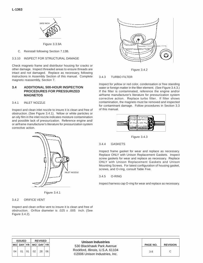
3.4.1 INLET NOZZLE
Inspect and clean inlet nozzle to insure it is clean and free ofobstruction. (See Figure 3.4.1). Yellow or white particles oran oily film in the inlet nozzle indicates moisture contaminationand possible lack of pressurization. Reference engine and/or airframe manufacturer’s literature for pressurization systemcorrective action.
19/32 INCH
Figure 3.4.1
3.4.2 ORIFICE VENT
Inspect and clean orifice vent to insure it is clean and free ofobstruction. Orifice diameter is .025 ± .005 inch. (SeeFigure 3.4.2).
Figure 3.4.2
3.4.3 TURBO FILTER
Inspect for yellow or red color, condensation or free standingwater or foreign matter in the filter element. (See Figure 3.4.3.)If the filter is contaminated, reference the engine and/orairframe manufacturer’s literature for pressurization systemcorrective action. Replace turbo filter. If filter showscontamination, the magneto must be removed and inspectedfor contaminant damage. Follow procedures in Section 3.3of this manual.
Figure 3.4.3
3.4.4 GASKETS
Inspect frame gasket for wear and replace as necessary.Replace ONLY with Unison Replacement Gaskets. Inspectscrew gaskets for wear and replace as necessary. ReplaceONLY with Unison Replacement Gaskets and UnisonMounting Screws. For latest configuration of housing gasket,screws, and O-ring, consult Table Five.
3.4.5 O-RING
Inspect harness cap O-ring for wear and replace as necessary.
INLET NOZZLE
Unison Industries530 Blackhawk Park Avenue
Rockford, Illinois, U.S.A. 61104©2006 Unison Industries, Inc.
ISSUED
MO DAY YR
04 01 91
REVISED
MO DAY YR
02 28 06
PAGE NO. REVISION
C
L-1363
4-1
4.0 OVERHAUL
Slick 4300/6300 Series Magnetos should be completelyoverhauled when conditions indicate. Magnetos must beoverhauled at every engine overhaul. In no case shouldmagnetos have in-service times greater than the TBO hourlimit for the engine on which it is installed.
Magnetos must be overhauled after a lightning strike on theaircraft and following a sudden engine stoppage.
The following parts must be replaced at overhaul.Additional parts may require replacement depending onconditions as determined during magneto inspection. Installonly Unison Replacement Parts.
ALL MAGNETOSCondenserDouble Sealed BearingBearing Cap AssemblyCoilImpulse CouplingOil SealContact Point KitRotor GearDistributor Block and Gear
PRESSURIZED MAGNETOS:In addition to above parts, the following components must bereplaced at every overhaul.
Frame GasketHousing ScrewHarness Cap ‘O’ Ring
A complete list of parts that must be replaced at overhaul canbe found in Table One (4300 Series) and Table Four (6300Series). Refer to tables One through Seven as you overhaulyour Slick Magneto.
Use only genuine Unison Industries manufactured partsobtained from Unison approved sources. Genuine Unisonparts are produced and inspected under rigorous proceduresto insure airworthiness and suitability in Slick magnetos. Partspurchased from sources other than Unison Industries, eventhough outwardly identical in appearance may not have hadthe required tests and inspections performed, may be differentin fabrication techniques and materials, and may bedangerous when installed in a Slick magneto. Salvagedmagneto parts, reworked parts obtained from non-Unisonapproved sources, or parts the service history of which isunknown or cannot be authenticated, may have beensubjected to unacceptable stresses or temperatures, or haveother hidden damage, not discernible through routine visualor usual nondestructive testing techniques. This may renderservice work with this par t, even though originallymanufactured by Unison Industries, unsuitable or unsafe foruse in a Slick magneto. Unison Industries expressly disclaimsany responsibility for malfunctions, failures, damage or injurycaused by use of non-Unison approved parts
Slick magnetos are engineered so that mechanical parts wearat a balanced rate. Consistent and complimentary wearpatterns establish the recommended maintenance intervalsdefined in Unison service literature, therefore used, serviceworn parts should never be used to troubleshoot or repair amagneto, nor should original parts be replaced by usedservice worn parts on magnetos being returned to service.Further, non-Unison manufactured parts may wear at unevenand different rates than original Unison manufactured parts,making Unison service literature an inappropriate guide toproper maintenance. Parts not manufactured by UnisonIndustries, even if FAA/PMA Approved may not fit or operatelike original Unison manufactured parts. FAA testing of PMAparts does not require operation on an engine or flight testsand does not require the test duration to exceed themaintenance intervals called out in Unison literature. Forthese reasons, used service worn parts or par ts notmanufactured by Unison Industries may adversely affectmagneto reliability in ways not anticipated by Unison Industriesand its service literature.
NOTE: AN ALTERNATIVE TO OVERHAUL ISCOMPLETE MAGNETO REPLACEMENT WITH ANEW SLICK MAGNETO. NEW SLICK MAGNETOSINCORPORATE ALL THE LATEST DESIGNFEATURES AND ARE A COST EFFECTIVEALTERNATIVE TO OVERHAUL.
4.1 OVERHAUL PROCEDURE - ALL MODELMAGNETOS
4.1.1 REMOVE MAGNETO FROM ENGINE
Follow procedures in Section 5.0, Removing Magneto fromEngine.
4.1.2 DISASSEMBLE MAGNETO
Proceed with magneto disassembly, following instructions inSections 6.0.
4.1.3 DISCARD PARTS TO BE REPLACED
Reference Table One, 4300 Series Overhaul Par tsReplacement List of Table Two, 6300 Series Overhaul PartsReplacement List. Discard all parts removed for overhaulreplacement and REPLACE WITH NEW UNISON PARTS.
Slick does not authorize the use of “used” par ts asreplacement parts for other magnetos. In many cases,subcomponent parts are matched at the factory and willfunction improperly if used in conjunction with other similarparts.
L-1363
Unison Industries530 Blackhawk Park Avenue
Rockford, Illinois, U.S.A. 61104©2006 Unison Industries, Inc.
ISSUED
MO DAY YR
04 01 91
REVISED
MO DAY YR
02 28 06
PAGE NO. REVISION
C4-2
NOTE: UNISON INDUSTRIES AUTHORIZES THEUSE OF ONLY UNISON REPLACEMENT PARTS INTHE MAINTENANCE AND/OR OVERHAUL OFUNISON INDUSTRIES EQUIPMENT. USE OF PARTSOR FASTENERS NOT MANUFACTURED ORAPPROVED BY UNISON VOIDS ANY AND ALLWARRANTIES AND MAY ADVERSELY AFFECT THEPERFORMANCE AND JEOPARDIZE THEAIRWORTHINESS OF THE MAGNETO.
4.1.4 MAGNETO REASSEMBLY
Proceed with magneto reassembly, following instructions inSection 7.0 of this manual.
4.2 ADDITIONAL PROCEDURES -PRESSURIZED MAGNETOS
In addition to the overhaul procedures outlined above, thefollowing must be performed.
4.2.1 DISCARD PARTS TO BE REPLACED
Discard parts as listed in Table Four.
4.2.2 INLET NOZZLE
Inspect and clean inlet nozzle to ensure it is clean and free ofobstruction. Presence of dirt or other contaminants indicatesthat the magneto pressurization system is not functioningproperly. Consult engine manufacturer’s manuals forcorrective action.
4.2.3 ORIFICE VENT
Inspect and clean orifice vent to ensure it is clean and free ofobstruction. Orifice diameter is .025 ± .005 inch.
4.2.4 INSPECT INTERIOR OF MAGNETO
Inspect inside of magneto for corrosion, oil and otherturbocharger contaminants. Clean if necessary and inspectaircraft pressurization system according to the engine and/orairframe manufacturer’s recommended procedures.
4.2.5 HARNESS CAP O-RING
Inspect O-ring in harness cap for cuts or other conditionsthat would inhibit a proper seal. Replace O-ring as necessary.
4.2.6 PRESSURE TEST MAGNETOPressure test magneto using instructions in Section 8.0 ofthis manual.
Unison Industries530 Blackhawk Park Avenue
Rockford, Illinois, U.S.A. 61104©2006 Unison Industries, Inc.
ISSUED
MO DAY YR
04 01 91
REVISED
MO DAY YR
02 28 06
PAGE NO. REVISION
C
L-1363
5-1
5.0 REMOVING MAGNETO FROMENGINE
A. To remove magneto, proceed as if you were timingthe magneto to the engine. Follow the enginemanufacturer’s procedure to set the engine to firecylinder number one, at the timing setting shown onthe engine data plate.
B. Remove the harness cap from the magneto byremoving the 3 screws that secure it to the magneto.When removing the cap, place a visible mark on theharness cap and an adjacent mark on the distributorhousing. Use this mark to ensure that the cap isproperly oriented upon reassembly.
C. To remove the magneto from the engine, proceedas follows:
1. Remove the P-lead wire that connects theignition switch to the magneto condenser.
Retard breaker magnetos only - Remove thelead that connects the retard contact points tothe starting circuit.
Pressurized magnetos only - Disconnectpressurization tube from magneto.
Tachometer drive magnetos only - Disconnecttachometer lead or pickup device.
2. Remove the 2 nuts, washers and clamps thatsecure the magneto to the engine.
NOTE: THE MAGNETO MUST BE REMOVED FROMTHE ENGINE FOR DISASSEMBLY AND INSPECTION.
D. To prevent any contaminant from entering themagneto accessory hole, cover the hole with asuitable material while the magneto is removed fromthe engine.
CAUTION: EXTRA CARE MUST BE TAKEN TOPREVENT ANY FOREIGN OBJECT FROM PASSINGINTO THE ENGINE THROUGH THE MAGNETOACCESSORY HOLE ON THE ENGINE WHEN THEMAGNETO IS REMOVED.
E. Remove Drive Gear/Lug.
In certain applications, it will be necessary to removethe drive gear/lug from the magneto. If applicable,remove drive gear/lug and save for reinstallation.Inspect drive gear/lug according to the enginemanufacturer’s recommended procedures.
NOTE: DO NOT STRIKE OR EXERT CRUSHINGFORCE AGAINST END OF ROTOR SHAFT TOREMOVE DRIVE GEAR.

THIS PAGE LEFT BLANK INTENTIONALLY.
Unison Industries530 Blackhawk Park Avenue
Rockford, Illinois, U.S.A. 61104©2006 Unison Industries, Inc.
ISSUED
MO DAY YR
04 01 91
REVISED
MO DAY YR
02 28 06
PAGE NO. REVISION
C
L-1363
6-1
6.0 MAGNETO DISASSEMBLY
Following are disassembly instructions for Slick 4300/6300Series Magnetos. The directions are generalized and referto both 4300/6300 Series Magnetos unless specifically noted.Refer to Table Two for specific part numbers and to Table One,Exploded Assembly Diagram.
The following parts must be replaced at overhaul. Additionalparts may require replacement depending on conditions asdetermined during magneto inspection. Install only UnisonReplacement Parts.
ALL MAGNETOS
CondenserDouble Sealed BearingBearing Cap Assembly CoilImpulse Coupling (where applicable)Oil SealContact Point KitRotor GearDistributor Block and Gear
PRESSURIZED MAGNETOS:
In addition to above parts, the following components must bereplaced at every overhaul.
Frame GasketHousing ScrewHarness Cap ‘O’ Ring
A complete list of parts that must be replaced at overhaul canbe found in Table One (4300 Series) and Table Four (6300Series). Refer to tables One through Seven as you overhaulyour Slick Magneto.
Use only genuine Unison Industries manufactured partsobtained from Unison approved sources. Genuine Unisonparts are produced and inspected under rigorous proceduresto insure airworthiness and suitability in Slick magnetos. Partspurchased from sources other than Unison, even thoughoutwardly identical in appearance may not have had therequired tests and inspections performed, may be different infabrication techniques and materials, and may be dangerouswhen installed in a Slick magneto. Salvaged magneto parts,reworked parts obtained from non-Unison approved sources,or parts the service history of which is unknown or cannot beauthenticated, may have been subjected to unacceptablestresses or temperatures, or have other hidden damage, notdiscernible through routine visual or usual nondestructivetesting techniques. This may render service work with thispar t, even though originally manufactured by UnisonIndustries, unsuitable or unsafe for use in a Slick magneto.Unison Industries expressly disclaims any responsibility formalfunctions, failures, damage or injury caused by use of non-Unison approved parts.
Slick magnetos are engineered so that mechanical parts wearat a balanced rate. Consistent and complimentary wearpatterns establish the recommended maintenance intervalsdefined in Unison service literature, therefore used, serviceworn parts should never be used to troubleshoot or repair amagneto, nor should original parts be replaced by usedservice worn parts on magnetos being returned to service.Further, non-Unison manufactured parts may wear at unevenand different rates than original Unison manufactured parts,making Unison service literature an inappropriate guide toproper maintenance. Parts not manufactured by UnisonIndustries, even if FAA/PMA Approved may not fit or operatelike original Unison manufactured parts. FAA testing of PMAparts does not require operation on an engine or flight testsand does not require the test duration to exceed themaintenance intervals called out in Unison literature. Forthese reasons, used service worn parts or par ts notmanufactured by Unison Industries may adversely affectmagneto reliability in ways not anticipated by Unison Industriesand its service literature.
NOTE: AN ALTERNATIVE TO OVERHAUL ISCOMPLETE MAGNETO REPLACEMENT WITH ANEW SLICK MAGNETO. NEW SLICK MAGNETOSINCORPORATE ALL THE LATEST DESIGNFEATURES AND ARE A COST EFFECTIVEALTERNATIVE TO OVERHAUL.
6.0.1 GENERAL ORDER OF DISASSEMBLY
Remove: Impulse CouplingWoodruff KeyDistributor Housing AssemblyCondenserRotor GearContact Breaker AssemblyRotor AssemblyBearings from ShaftCoilOil Seal
6.1 REMOVE IMPULSE COUPLING
A. Remove cotter pin, nut, washer, bushing and drivegear where applicable. (Section 5.0E.)
B. Grasp shell of impulse coupling assembly and gentlypull the assembly outward to clear the latching earsof the impulse hub assembly. (See Figure 6.1.)
L-1363
Unison Industries530 Blackhawk Park Avenue
Rockford, Illinois, U.S.A. 61104©2006 Unison Industries, Inc.
ISSUED
MO DAY YR
04 01 91
REVISED
MO DAY YR
02 28 06
PAGE NO. REVISION
C
Figure 6.1
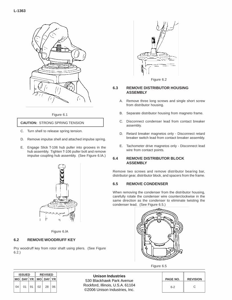
CAUTION: STRONG SPRING TENSION
C. Turn shell to release spring tension.
D. Remove impulse shell and attached impulse spring.
E. Engage Slick T-106 hub puller into grooves in thehub assembly. Tighten T-106 puller bolt and removeimpulse coupling hub assembly. (See Figure 6.lA.)
Figure 6.lA
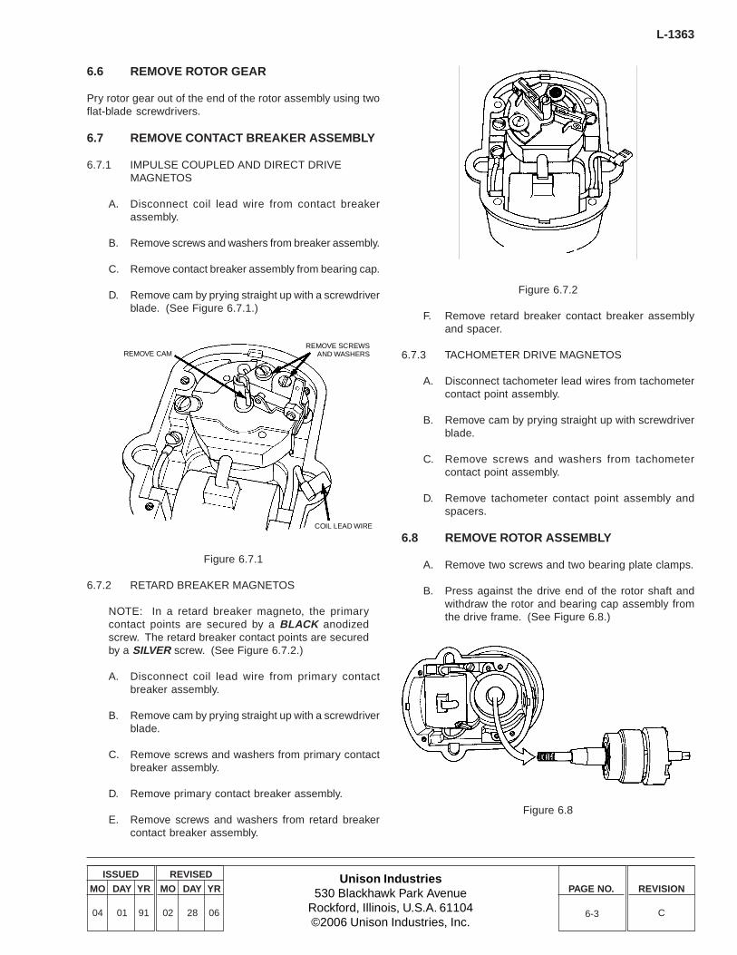
6.2 REMOVE WOODRUFF KEY
Pry woodruff key from rotor shaft using pliers. (See Figure6.2.)
Figure 6.2
6.3 REMOVE DISTRIBUTOR HOUSINGASSEMBLY
A. Remove three long screws and single short screwfrom distributor housing.
B. Separate distributor housing from magneto frame.
C. Disconnect condenser lead from contact breakerassembly.
D. Retard breaker magnetos only - Disconnect retardbreaker switch lead from contact breaker assembly.
E. Tachometer drive magnetos only - Disconnect leadwire from contact points.
6.4 REMOVE DISTRIBUTOR BLOCKASSEMBLY
Remove two screws and remove distributor bearing bar,distributor gear, distributor block, and spacers from the frame.
6.5 REMOVE CONDENSER
When removing the condenser from the distributor housing,carefully rotate the condenser wire counterclockwise in thesame direction as the condenser to eliminate twisting thecondenser lead. (See Figure 6.5.)
Figure 6.5
6-2
Unison Industries530 Blackhawk Park Avenue
Rockford, Illinois, U.S.A. 61104©2006 Unison Industries, Inc.
ISSUED
MO DAY YR
04 01 91
REVISED
MO DAY YR
02 28 06
PAGE NO. REVISION
C
L-1363
6-3
6.6 REMOVE ROTOR GEAR
Pry rotor gear out of the end of the rotor assembly using twoflat-blade screwdrivers.
6.7 REMOVE CONTACT BREAKER ASSEMBLY
6.7.1 IMPULSE COUPLED AND DIRECT DRIVEMAGNETOS
A. Disconnect coil lead wire from contact breakerassembly.
B. Remove screws and washers from breaker assembly.
C. Remove contact breaker assembly from bearing cap.
D. Remove cam by prying straight up with a screwdriverblade. (See Figure 6.7.1.)
Figure 6.7.1
6.7.2 RETARD BREAKER MAGNETOS
NOTE: In a retard breaker magneto, the primarycontact points are secured by a BLACK anodizedscrew. The retard breaker contact points are securedby a SILVER screw. (See Figure 6.7.2.)
A. Disconnect coil lead wire from primary contactbreaker assembly.
B. Remove cam by prying straight up with a screwdriverblade.
C. Remove screws and washers from primary contactbreaker assembly.
D. Remove primary contact breaker assembly.
E. Remove screws and washers from retard breakercontact breaker assembly.
Figure 6.7.2
F. Remove retard breaker contact breaker assemblyand spacer.
6.7.3 TACHOMETER DRIVE MAGNETOS
A. Disconnect tachometer lead wires from tachometercontact point assembly.
B. Remove cam by prying straight up with screwdriverblade.
C. Remove screws and washers from tachometercontact point assembly.
D. Remove tachometer contact point assembly andspacers.
6.8 REMOVE ROTOR ASSEMBLY
A. Remove two screws and two bearing plate clamps.
B. Press against the drive end of the rotor shaft andwithdraw the rotor and bearing cap assembly fromthe drive frame. (See Figure 6.8.)
Figure 6.8
REMOVE CAMREMOVE SCREWS
AND WASHERS
COIL LEAD WIRE
L-1363
Unison Industries530 Blackhawk Park Avenue
Rockford, Illinois, U.S.A. 61104©2006 Unison Industries, Inc.
ISSUED
MO DAY YR
04 01 91
REVISED
MO DAY YR
02 28 06
PAGE NO. REVISION
C6-4
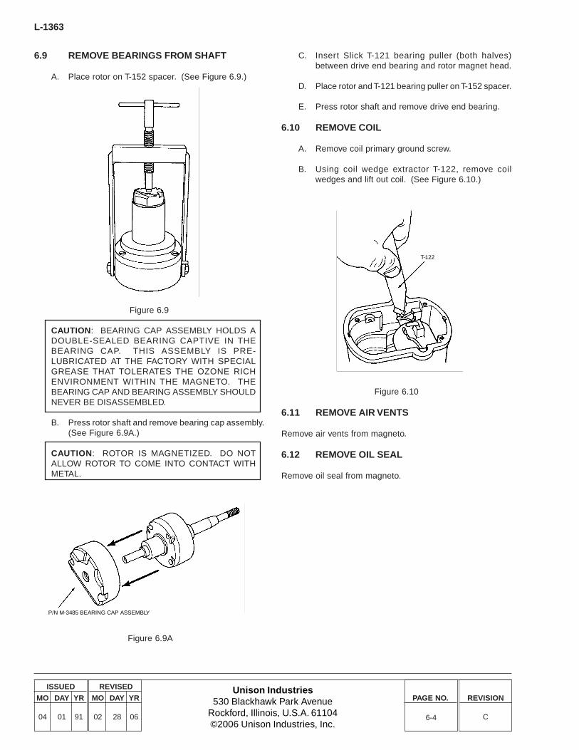
6.9 REMOVE BEARINGS FROM SHAFT
A. Place rotor on T-152 spacer. (See Figure 6.9.)
Figure 6.9
CAUTION: BEARING CAP ASSEMBLY HOLDS ADOUBLE-SEALED BEARING CAPTIVE IN THEBEARING CAP. THIS ASSEMBLY IS PRE-LUBRICATED AT THE FACTORY WITH SPECIALGREASE THAT TOLERATES THE OZONE RICHENVIRONMENT WITHIN THE MAGNETO. THEBEARING CAP AND BEARING ASSEMBLY SHOULDNEVER BE DISASSEMBLED.
B. Press rotor shaft and remove bearing cap assembly.(See Figure 6.9A.)
CAUTION: ROTOR IS MAGNETIZED. DO NOTALLOW ROTOR TO COME INTO CONTACT WITHMETAL.
Figure 6.9A
Figure 6.10
6.11 REMOVE AIR VENTS
Remove air vents from magneto.
6.12 REMOVE OIL SEAL
Remove oil seal from magneto.
C. Insert Slick T-121 bearing puller (both halves)between drive end bearing and rotor magnet head.
D. Place rotor and T-121 bearing puller on T-152 spacer.
E. Press rotor shaft and remove drive end bearing.
6.10 REMOVE COIL
A. Remove coil primary ground screw.
B. Using coil wedge extractor T-122, remove coilwedges and lift out coil. (See Figure 6.10.)
P/N M-3485 BEARING CAP ASSEMBLY
T-122
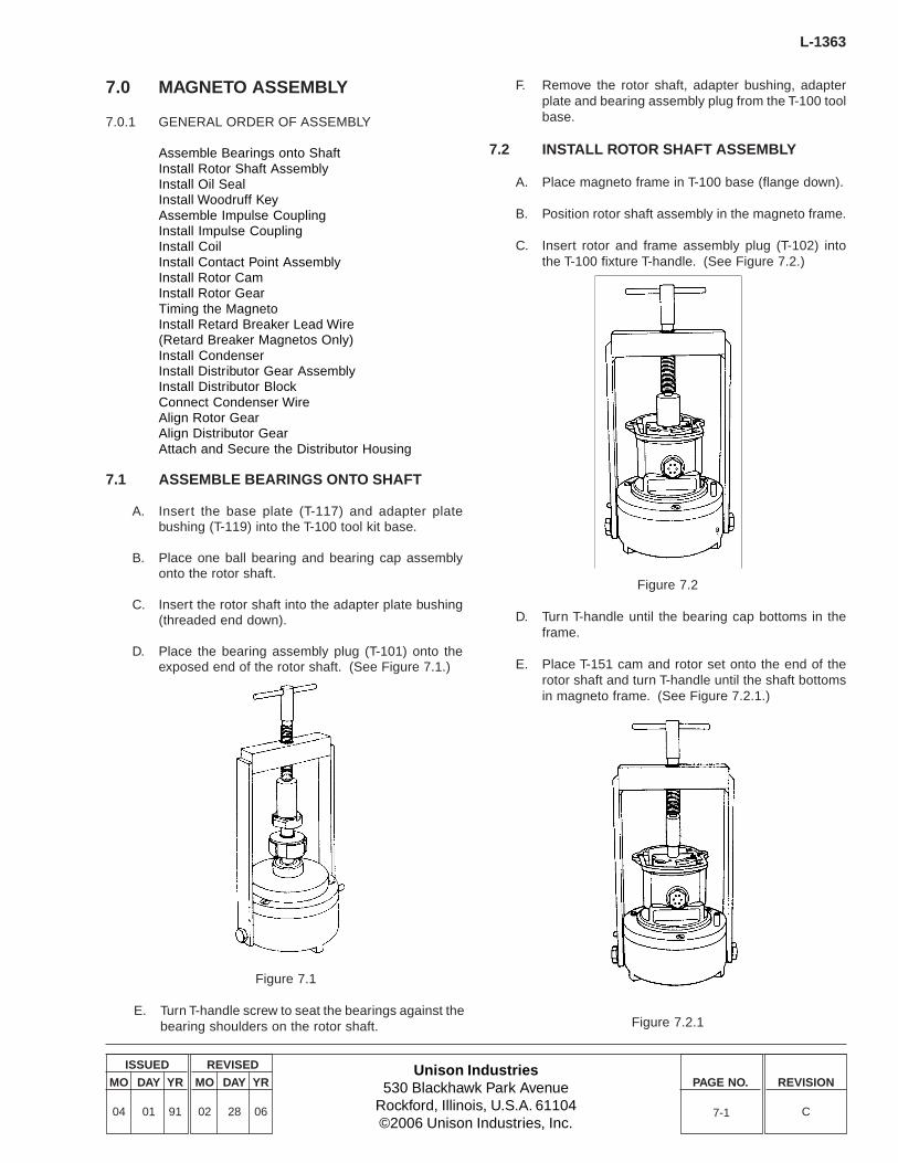
Unison Industries530 Blackhawk Park Avenue
Rockford, Illinois, U.S.A. 61104©2006 Unison Industries, Inc.
ISSUED
MO DAY YR
04 01 91
REVISED
MO DAY YR
02 28 06
PAGE NO. REVISION
C
L-1363
7-1
7.0 MAGNETO ASSEMBLY
7.0.1 GENERAL ORDER OF ASSEMBLY
Assemble Bearings onto ShaftInstall Rotor Shaft AssemblyInstall Oil SealInstall Woodruff KeyAssemble Impulse CouplingInstall Impulse CouplingInstall CoilInstall Contact Point AssemblyInstall Rotor CamInstall Rotor GearTiming the MagnetoInstall Retard Breaker Lead Wire(Retard Breaker Magnetos Only)Install CondenserInstall Distributor Gear AssemblyInstall Distributor BlockConnect Condenser WireAlign Rotor GearAlign Distributor GearAttach and Secure the Distributor Housing
7.1 ASSEMBLE BEARINGS ONTO SHAFT
A. Insert the base plate (T-117) and adapter platebushing (T-119) into the T-100 tool kit base.
B. Place one ball bearing and bearing cap assemblyonto the rotor shaft.
C. Insert the rotor shaft into the adapter plate bushing(threaded end down).
D. Place the bearing assembly plug (T-101) onto theexposed end of the rotor shaft. (See Figure 7.1.)
Figure 7.1
E. Turn T-handle screw to seat the bearings against thebearing shoulders on the rotor shaft.
F. Remove the rotor shaft, adapter bushing, adapterplate and bearing assembly plug from the T-100 toolbase.
7.2 INSTALL ROTOR SHAFT ASSEMBLY
A. Place magneto frame in T-100 base (flange down).
B. Position rotor shaft assembly in the magneto frame.
C. Insert rotor and frame assembly plug (T-102) intothe T-100 fixture T-handle. (See Figure 7.2.)
Figure 7.2
D. Turn T-handle until the bearing cap bottoms in theframe.
E. Place T-151 cam and rotor set onto the end of therotor shaft and turn T-handle until the shaft bottomsin magneto frame. (See Figure 7.2.1.)
Figure 7.2.1
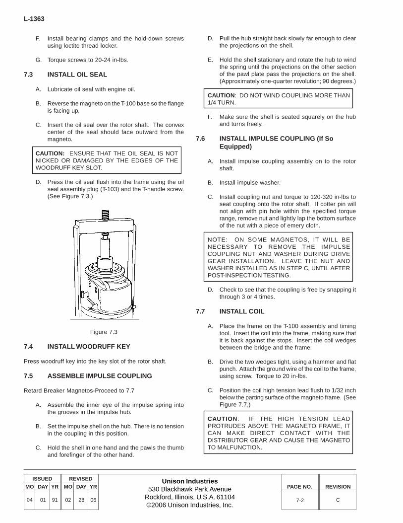
L-1363
Unison Industries530 Blackhawk Park Avenue
Rockford, Illinois, U.S.A. 61104©2006 Unison Industries, Inc.
ISSUED
MO DAY YR
04 01 91
REVISED
MO DAY YR
02 28 06
PAGE NO. REVISION
C
F. Install bearing clamps and the hold-down screwsusing loctite thread locker.
G. Torque screws to 20-24 in-lbs.
7.3 INSTALL OIL SEAL
A. Lubricate oil seal with engine oil.
B. Reverse the magneto on the T-100 base so the flangeis facing up.
C. Insert the oil seal over the rotor shaft. The convexcenter of the seal should face outward from themagneto.
CAUTION: ENSURE THAT THE OIL SEAL IS NOTNICKED OR DAMAGED BY THE EDGES OF THEWOODRUFF KEY SLOT.
D. Press the oil seal flush into the frame using the oilseal assembly plug (T-103) and the T-handle screw.(See Figure 7.3.)
7-2
D. Pull the hub straight back slowly far enough to clearthe projections on the shell.
E. Hold the shell stationary and rotate the hub to windthe spring until the projections on the other sectionof the pawl plate pass the projections on the shell.(Approximately one-quarter revolution; 90 degrees.)
CAUTION: DO NOT WIND COUPLING MORE THAN1/4 TURN.
F. Make sure the shell is seated squarely on the huband turns freely.
7.6 INSTALL IMPULSE COUPLING (If SoEquipped)
A. Install impulse coupling assembly on to the rotorshaft.
B. Install impulse washer.
C. Install coupling nut and torque to 120-320 in-lbs toseat coupling onto the rotor shaft. If cotter pin willnot align with pin hole within the specified torquerange, remove nut and lightly lap the bottom surfaceof the nut with a piece of emery cloth.
NOTE: ON SOME MAGNETOS, IT WILL BENECESSARY TO REMOVE THE IMPULSECOUPLING NUT AND WASHER DURING DRIVEGEAR INSTALLATION. LEAVE THE NUT ANDWASHER INSTALLED AS IN STEP C, UNTIL AFTERPOST-INSPECTION TESTING.
D. Check to see that the coupling is free by snapping itthrough 3 or 4 times.
7.7 INSTALL COIL
A. Place the frame on the T-100 assembly and timingtool. Insert the coil into the frame, making sure thatit is back against the stops. Insert the coil wedgesbetween the bridge and the frame.
B. Drive the two wedges tight, using a hammer and flatpunch. Attach the ground wire of the coil to the frame,using screw. Torque to 20 in-lbs.
C. Position the coil high tension lead flush to 1/32 inchbelow the parting surface of the magneto frame. (SeeFigure 7.7.)
CAUTION: IF THE HIGH TENSION LEADPROTRUDES ABOVE THE MAGNETO FRAME, ITCAN MAKE DIRECT CONTACT WITH THEDISTRIBUTOR GEAR AND CAUSE THE MAGNETOTO MALFUNCTION.
Figure 7.3
7.4 INSTALL WOODRUFF KEY
Press woodruff key into the key slot of the rotor shaft.
7.5 ASSEMBLE IMPULSE COUPLING
Retard Breaker Magnetos-Proceed to 7.7
A. Assemble the inner eye of the impulse spring intothe grooves in the impulse hub.
B. Set the impulse shell on the hub. There is no tensionin the coupling in this position.
C. Hold the shell in one hand and the pawls the thumband forefinger of the other hand.

Unison Industries530 Blackhawk Park Avenue
Rockford, Illinois, U.S.A. 61104©2006 Unison Industries, Inc.
ISSUED
MO DAY YR
04 01 91
REVISED
MO DAY YR
02 28 06
PAGE NO. REVISION
C
L-1363
Figure 7.7
7.8 INSTALL CONTACT POINTS
7.8.1 PRIMARY CONTACT POINTS - ALL MAGNETOS
A. Attach contact point assembly on the bearing capusing appropriate screw.
NOTE: ON RETARD BREAKER MAGNETOS, THEPRIMARY POINTS ARE SECURED WITH A BLACKANODIZED SCREW.
CAUTION: RETARD BREAKER MAGNETOS USEDIFFERENT LENGTH SCREWS TO SECURE THECONTACT BREAKER ASSEMBLIES. USE OFINCORRECT MOUNTING SCREWS WILL DAMAGEUPPER MAGNETO BEARING AND CAUSEPOSSIBLE MAGNETO FAILURE.
7.8.2 RETARD BREAKER CONTACT POINTS -RETARD BREAKER MAGNETOS ONLY
NOTE: INSTALL PRIMARY POINT ASSEMBLYBEFORE INSTALLING RETARD POINT ASSEMBLY.
A. Place spacer on bearing cap and attach retardcontact points assembly using silver screw and plainwasher.
B. Do not tighten screws until magneto is timed.
7.8.3 TACHOMETER DRIVE CONTACT POINTS -TACHOMETER DRIVE MAGNETOS ONLY
NOTE: INSTALL PRIMARY POINT ASSEMBLYBEFORE INSTALLING TACHOMETER POINTASSEMBLY.
A. Place tachometer contact points on bearing cap andsecure using two screws and plain washers.
B. Do not tighten screws until magneto is timed.
7.9 INSTALL ROTOR CAM
A. Install cam using a light hammer and T-151 cam androtor set.
B. Drive the cam until it bottoms in the rotor cam slot.(See Figure 7.9.)
Figure 7.9
7.10 TIME THE MAGNETO
NOTE: FOR RETARD BREAKER MAGNETOS, THEPRIMARY POINTS MUST BE SET FIRST. THERETARD (SECONDARY) POINTS ARE SET INREFERENCE TO THE PRIMARY POINTS AND THEPRIMARY POINTS MUST BE SET CORRECTLY TOENSURE ACCURACY OF RETARD CONTACTSETTINGS.
7.10.1 SET PRIMARY POINTS - ALL MAGNETOS
A. Place the magneto on the T-125 base, flange down.
6300 Series Magnetos - Remove T-509 timing base adapter.
Retard Breaker Magnetos - Install the T-123 timing plug onthe rotor shaft before placing the magneto on the T-125 rotorbase.
Impulse Coupled Magnetos - Do not use T-123 timing plug.
Direct-Drive Magnetos - Install the T-123 timing plug on therotor shaft before placing the magneto on the T-125 base.
B. Looking directly down on the magneto, align themagneto so that the coil is oriented in the 12 o’clockposition.
C. Insert T-150 “E” Gap Gauge (Figure 7.10.1) betweenthe pole laminations in the rotor shaft and the polelaminations in the frame.
7-3
FLUSH TO1/32 BELOW
PARTING SURFACEOF FRAME
HIGH TENSIONLEAD COIL
SPRING LOADED BRUSH
T-151
CAM
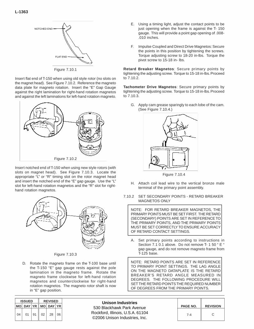
L-1363
Unison Industries530 Blackhawk Park Avenue
Rockford, Illinois, U.S.A. 61104©2006 Unison Industries, Inc.
ISSUED
MO DAY YR
04 01 91
REVISED
MO DAY YR
02 28 06
PAGE NO. REVISION
C
Figure 7.10.1
Insert flat end of T-150 when using old style rotor (no slots onthe magnet head). See Figure 7.10.2. Reference the magnetodata plate for magneto rotation. Insert the “E” Gap Gaugeagainst the right lamination for right-hand rotation magnetosand against the left laminations for left-hand rotation magneto.
Figure 7.10.2
Insert notched end of T-150 when using new style rotors (withslots on magnet head). See Figure 7.10.3. Locate theappropriate “L” or “R” timing slot on the rotor magnet headand insert the notched end of the “E” gap gauge. Use the “L”slot for left-hand rotation magnetos and the “R” slot for right-hand rotation magnetos.
E. Using a timing light, adjust the contact points to bejust opening when the frame is against the T- 150gauge. This will provide a point gap opening of .008-.010 inches.
F. Impulse Coupled and Direct Drive Magnetos: Securethe points in this position by tightening the screws.Torque adjusting screw to 18-20 in-lbs. Torque thepivot screw to 15-18 in- lbs.
Retard Breaker Magnetos: Secure primary points bytightening the adjusting screw. Torque to 15-18 in-lbs. Proceedto 7.10.2.
Tachometer Drive Magnetos: Secure primary points bytightening the adjusting screw. Torque to 15-18 in-lbs. Proceedto 7.10.3.
G. Apply cam grease sparingly to each lobe of the cam.(See Figure 7.10.4.)
Figure 7.10.3
D. Rotate the magneto frame on the T-100 base untilthe T-150 “E” gap gauge rests against the polelamination in the magneto frame. Rotate themagneto frame clockwise for left-hand rotationmagnetos and counterclockwise for right-handrotation magnetos. The magneto rotor shaft is nowin “E” gap position.
Figure 7.10.4
H. Attach coil lead wire to the vertical bronze maleterminal of the primary point assembly.
7.10.2 SET SECONDARY POINTS - RETARD BREAKERMAGNETOS ONLY
NOTE: FOR RETARD BREAKER MAGNETOS, THEPRIMARY POINTS MUST BE SET FIRST. THE RETARD(SECONDARY) POINTS ARE SET IN REFERENCE TOTHE PRIMARY POINTS, AND THE PRIMARY POINTSMUST BE SET CORRECTLY TO ENSURE ACCURACYOF RETARD CONTACT SETTINGS.
A. Set primary points according to instructions inSection 7.1 0.1 above. Do not remove T- 1 50 “ E “gap gauge, and do not remove magneto frame fromT-125 base.
NOTE: RETARD POINTS ARE SET IN REFERENCETO PRIMARY POINT SETTINGS. THE LAG ANGLEON THE MAGNETO DATAPLATE IS THE RETARDBREAKER’S RETARD ANGLE MEASURED INDEGREES. THE FOLLOWING PROCEDURE WILLSET THE RETARD POINTS THE REQUIRED NUMBEROF DEGREES FROM THE PRIMARY POINTS.
7-4
NOTCHED END
FLAT END
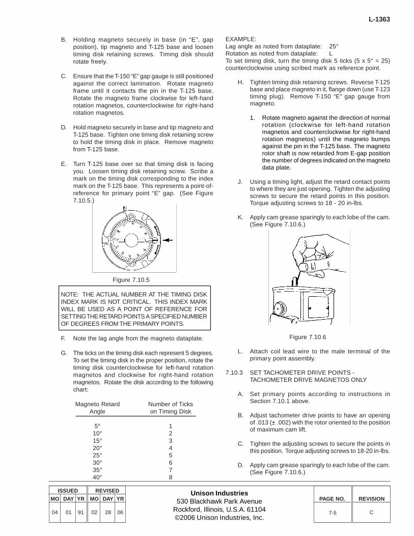
Unison Industries530 Blackhawk Park Avenue
Rockford, Illinois, U.S.A. 61104©2006 Unison Industries, Inc.
ISSUED
MO DAY YR
04 01 91
REVISED
MO DAY YR
02 28 06
PAGE NO. REVISION
C
L-1363
7-5
B. Holding magneto securely in base (in “E”, gapposition), tip magneto and T-125 base and loosentiming disk retaining screws. Timing disk shouldrotate freely.
C. Ensure that the T-150 “E” gap gauge is still positionedagainst the correct lamination. Rotate magnetoframe until it contacts the pin in the T-125 base.Rotate the magneto frame clockwise for left-handrotation magnetos, counterclockwise for right-handrotation magnetos.
D. Hold magneto securely in base and tip magneto andT-125 base. Tighten one timing disk retaining screwto hold the timing disk in place. Remove magnetofrom T-125 base.
E. Turn T-125 base over so that timing disk is facingyou. Loosen timing disk retaining screw. Scribe amark on the timing disk corresponding to the indexmark on the T-125 base. This represents a point-of-reference for primary point “E” gap. (See Figure7.10.5.)
EXAMPLE:Lag angle as noted from dataplate: 25°Rotation as noted from dataplate: LTo set timing disk, turn the timing disk 5 ticks (5 x 5° = 25)counterclockwise using scribed mark as reference point.
H. Tighten timing disk retaining screws. Reverse T-125base and place magneto in it, flange down (use T-123timing plug). Remove T-150 “E” gap gauge frommagneto.
1. Rotate magneto against the direction of normalrotation (clockwise for left-hand rotationmagnetos and counterclockwise for right-handrotation magnetos) until the magneto bumpsagainst the pin in the T-125 base. The magnetorotor shaft is now retarded from E-gap positionthe number of degrees indicated on the magnetodata plate.
J. Using a timing light, adjust the retard contact pointsto where they are just opening. Tighten the adjustingscrews to secure the retard points in this position.Torque adjusting screws to 18 - 20 in-lbs.
K. Apply cam grease sparingly to each lobe of the cam.(See Figure 7.10.6.)
Figure 7.10.5
NOTE: THE ACTUAL NUMBER AT THE TIMING DISKINDEX MARK IS NOT CRITICAL. THIS INDEX MARKWILL BE USED AS A POINT OF REFERENCE FORSETTING THE RETARD POINTS A SPECIFIED NUMBEROF DEGREES FROM THE PRIMARY POINTS.
F. Note the lag angle from the magneto dataplate.
G. The ticks on the timing disk each represent 5 degrees.To set the timing disk in the proper position, rotate thetiming disk counterclockwise for left-hand rotationmagnetos and clockwise for right-hand rotationmagnetos. Rotate the disk according to the followingchart:
Magneto Retard Number of TicksAngle on Timing Disk
5° 110° 215° 320° 425° 530° 635° 740° 8
Figure 7.10.6
L. Attach coil lead wire to the male terminal of theprimary point assembly.
7.10.3 SET TACHOMETER DRIVE POINTS -TACHOMETER DRIVE MAGNETOS ONLY
A. Set primary points according to instructions inSection 7.10.1 above.
B. Adjust tachometer drive points to have an openingof .013 (± .002) with the rotor oriented to the positionof maximum cam lift.
C. Tighten the adjusting screws to secure the points inthis position. Torque adjusting screws to 18-20 in-lbs.
D. Apply cam grease sparingly to each lobe of the cam.(See Figure 7.10.6.)
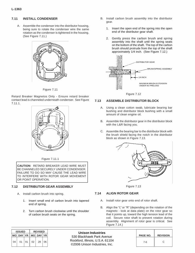
L-1363
Unison Industries530 Blackhawk Park Avenue
Rockford, Illinois, U.S.A. 61104©2006 Unison Industries, Inc.
ISSUED
MO DAY YR
04 01 91
REVISED
MO DAY YR
02 28 06
PAGE NO. REVISION
C
7.11 INSTALL CONDENSER
A. Assemble the condenser into the distributor housing,being sure to rotate the condenser wire the samerotation as the condenser is tightened in the housing.(See Figure 7.11.)
Figure 7.11
Retard Breaker Magnetos Only - Ensure retard breakercontact lead is channeled underneath condenser. See Figure7.11.1.
B. Install carbon brush assembly into the distributorgear.
1. Insert the open end of the spring into the openend of the distributor gear shaft.
2. Gently press the carbon brush and springassembly into the shaft until the spring seatson the bottom of the shaft. The top of the carbonbrush should protrude from the top of the shaftapproximately 1/4 inch. (See Figure 7.12.)
Figure 7.11.1
CAUTION: RETARD BREAKER LEAD WIRE MUSTBE CHANNELED SECURELY UNDER CONDENSER.FAILURE TO DO SO MAY CAUSE THE LEAD WIRETO INTERFERE WITH ROTOR GEAR MOVEMENTOR POINT OPERATION.
7.12 DISTRIBUTOR GEAR ASSEMBLY
A. Install carbon brush into spring.
1. Insert small end of carbon brush into taperedend of spring.
2. Turn carbon brush clockwise until the shoulderof carbon brush seats on the spring.
Figure 7.12
7.13 ASSEMBLE DISTRIBUTOR BLOCK
A. Using a clean cotton swab, lubricate bearing barbushing and distributor block bushing with a smallamount of clean engine oil.
B. Assemble the distributor gear in the distributor blockwith the L&R facing you.
C. Assemble the bearing bar to the distributor block withthe brush shield facing the notch in the distributorblock as shown in Figure 7.13.
Figure 7.13
7.14 ALIGN ROTOR GEAR
A. Install rotor gear onto end of rotor shaft.
B. Align the “L” or “R” (depending on the rotation of themagneto - look at data plate) on the rotor gear sothat it points up, toward the high tension lead of thecoil. Secure rotor shaft to prevent rotation duringassembly. Alignment of rotor gear is critical. SeeFigure 7.14.)
7-6
DISTRIBUTOR GEAR
BRUSH/SPRING ASSEMBLY
1/4 INCH
MAXIMUM BRUSH EXTENSIONUNDER NO PRELOAD
Unison Industries530 Blackhawk Park Avenue
Rockford, Illinois, U.S.A. 61104©2006 Unison Industries, Inc.
ISSUED
MO DAY YR
04 01 91
REVISED
MO DAY YR
02 28 06
PAGE NO. REVISION
C
L-1363
7-7
Figure 7.14
7.15 ALIGN DISTRIBUTOR GEAR
A. Align the “L” or “R” hole in the distributor gear withthe “L “or “R” in the distributor block. Use “L” for left-hand rotation and “R” for right-hand rotationmagnetos.
B. Lock the distributor gear in place with the T-118 timingpin through the appropriate hole in the block andgear.
C. Place distributor block spacers on magneto frame.(See Figure 7.15.)
Figure 7.15
D. Place the distributor block on magneto frame. Thedistributor gear and rotor gear are properly meshedwhen the index mark on the rotor gear aligns withthe reference mark on the distributor block. (SeeFigure 7.15.A.)
Figure 7.15.A
E. Secure the distributor block to frame using screwsprovided.
7.16 CONNECT CONDENSER WIRE
A. Connect condenser wire to the primary terminal ofthe contact assembly.
B. Attach the terminal with the lead pointing left. (SeeFigure 7.16.)
Figure 7.16
7.17 CONNECT RETARD CONTACT WIRE
A. Connect retard terminal wire to retard contact points.(See Figure 7.17.)
POINT ASSEMBLYCONDENSER LEAD WIRE
(FROM LEFT)
BEARING CAP
L-1363
Unison Industries530 Blackhawk Park Avenue
Rockford, Illinois, U.S.A. 61104©2006 Unison Industries, Inc.
ISSUED
MO DAY YR
04 01 91
REVISED
MO DAY YR
02 28 06
PAGE NO. REVISION
C
Figure 7.17
7.18 CONNECT TACHOMETER CONTACT WIRE
A. Connect wires to tachometer contact points. (SeeFigure 7.18 )
7-8
7.21 SECURE DISTRIBUTOR HOUSING
A. Secure the housing with three screws and one screw.Torque to 24 in-lbs.
B. Remove T-118 timing pin.
CAUTION: DO NOT ROTATE MAGNETO ROTORSHAFT WITH THE T-118 TIMING PIN INSERTED INTHE DISTRIBUTOR BLOCK. IF ROTOR SHAFT ISROTATED WITH TIMING PIN INSERTED, THEMAGNETO MUST BE DISASSEMBLED ANDINSPECTED FOR DISTRIBUTOR BLOCK AND GEARDAMAGE.
Figure 7.18
7.19 ATTACH THE DISTRIBUTOR HOUSING -NON PRESSURIZED MAGNETOS
A. Place the distributor housing onto the magnetoframe.
7.20 ATTACH THE DISTRIBUTOR HOUSING -PRESSURIZED MAGNETOS
A. Install housing gasket.
B. Place the distributor housing onto the magnetoframe.
CAUTION: MAKE SURE THE CARBON BRUSH ISCONTAINED IN THE DISTRIBUTOR SHAFT DURINGASSEMBLY. IF THE CARBON BRUSH CATCHES ONTHE SIDE OF THE DISTRIBUTOR SHAFT, THE COILSTRAP WILL BE BENT INTO THE WRONG POSITIONDURING ASSEMBLY.
Unison Industries530 Blackhawk Park Avenue
Rockford, Illinois, U.S.A. 61104©2006 Unison Industries, Inc.
ISSUED
MO DAY YR
04 01 91
REVISED
MO DAY YR
02 28 06
PAGE NO. REVISION
C
L-1363
8-1
8.0 POST-ASSEMBLY TESTING
Complete Magneto Reassembly, Section 7.0. Ensure thatthe T-118 Timing Pin has been removed.
8.1 PRE-TEST PREPARATION
A. Mount the magneto on a suitable test stand in thesame position as installed on the engine.
B. Install a Slick High-Temperature Ignition Harness onthe magneto and connect each output led to a 5mmspark gap.
CAUTION: DO NOT OPERATE THE MAGNETOUNLESS THE IGNITION HARNESS IS INSTALLEDAND THE OUTPUT LEADS ARE CONNECTED TOTHE 5mm GAP.
8.2 IMPULSE COUPLING
A. Rotate the test stand drive pulley in the samedirection of rotation as stated on the magneto dataplate.
B. The impulse coupling should engage the stop pin inthe magneto frame below approximately 200 RPM.If the impulse coupling pawls slip past the stop pinor engage intermittently, the impulse coupling is notoperating properly,
8.3 COMING-IN SPEED
A. Determine the lowest speed at which the magnetocan be turned and still spark all 5mm gaps withoutmissing.
B. The test gap must fire consistently at 200 RPMmaximum on non-impulse magnetos and 350 RPMmaximum on impulse coupled magnetos.
8.4 HIGH-SPEED TEST
A. 4300 Series Magnetos
1. Operate the magneto at 1000, 2000 and 3000RPM for five minute at each speed setting.
2. Observe sparking regularity at the spark gaps.Magneto must produce a consistent spark at allspeed settings.
8.5 LONG TERM TEST (OPTIONAL)
A. 4300 Series Magnetos
1. Test run the magneto for a minimum of threehours. Operate the magneto at 1725 RPM forthe first two hours and 3400 RPM for theremaining hour.
2. Regular and consistent firing of the spark gapsis required during the entire test.
B. 6300 Series magnetos
1. Test run the magneto for a minimum of threehours. Operate the magneto at 3000 RPM forthe first two hours and 4500 RPM for theremaining hour.
2. Regular and consistent tiring of the spark gapsis required during the entire test.
8.6 TEMPERATURE TEST
Measure the temperature on the outside surface of themagneto frame during the long-term test at the highest RPMsetting. The magneto will generate heat during normaloperation. Maximum temperature on the outside surface ofthe magneto frame is 175°F when tested at room temperature.
8.7 PRESSURE TESTING - PRESSURIZEDMAGNETOS ONLY
After magneto assembly, install a pressurized harness capand apply 15 psi filtered air to the inlet nozzle of the magneto.Air flow at 15 psi is 11-40 standard cubic feet per hour (SCFH).If flow is excessive, reposition gaskets and retorque housingand harness cap screws. Screws should be torqued to 21-25in. lbs. (See Figure 8.8 for Test Apparatus Details.) Testingshould be conducted with magneto at room temperature.
L-1363
Unison Industries530 Blackhawk Park Avenue
Rockford, Illinois, U.S.A. 61104©2006 Unison Industries, Inc.
ISSUED
MO DAY YR
04 01 91
REVISED
MO DAY YR
02 28 06
PAGE NO. REVISION
C8-2
Figure 8.8
Note: Flow meter may be obtained from:Dwyer Instruments, Inc.PO Box 373Michigan City, IN 46360(219-879-8868)Order Model MMA-7
8.8 PREFLIGHT OPERATIONAL CHECK
Before flight or after magneto maintenance, observe engineoperation while running on both left or right magnetosindividually. Both magnetos should operate normally andengine should operate within parameters outlined in theengine manufacturer’s operating manual.
WARNING: DO NOT FLY AIRCRAFT IF BOTHMAGNETOS ARE NOT FUNCTIONING PROPERLY.
PRESSURE GAUGE
TO MAGNETO
FILTER
AIR SUPPLY
REGULATORFLOW METER
MAX. FLOW OF 40 SCFHAT 15 PSI
Unison Industries530 Blackhawk Park Avenue
Rockford, Illinois, U.S.A. 61104©2006 Unison Industries, Inc.
ISSUED
MO DAY YR
04 01 91
REVISED
MO DAY YR
02 28 06
PAGE NO. REVISION
C
L-1363
9-1/(9-2 Blank)
9.0 POSTFLIGHT OPERATIONALCHECK
After flight, observe engine operation while running on bothleft or right magnetos individually. Both magnetos shouldoperate normally and engine should operate withinparameters outlined in the engine manufacturer’s operatingmanual.
WARNING: DO NOT ATTEMPT FURTHER FLIGHTIF BOTH MAGNETOS ARE NOT FUNCTIONINGNORMALLY.
9.1 MAINTENANCE CHECKLIST
A/C Type Engine Make/ModelN# Total Time on EngineMagneto P/N Total Time on MagnetoMagneto S/N Date
EVERY 100 HOURS
ADJUST TIMING TO ENGINE Sec. 3.2.1
INSPECTIONSWiring Conditions and Connections Sec. 3.2.2Vent Holes-Non-Pressurized Magnetos Sec. 3.2.3P-Lead Attachment Sec. 3.2.4Turbo Filter (Pressurized Mags Only) See. 3.2.7Inlet Nozzle (Pressurized Magnetos Only) See. 3.2.8Orifice Vent (Pressurized Magnetos Only) See. 3.2.9
EVERY 500 HOURS
GENERAL CLEANING Sec. 3.3.1
INSPECTIONS-ALL MAGNETOSBall Bearing Assembly Sec. 3.3.2Impulse Coupling Sec. 3.3.4Coil Sec. 3.3.5Condenser Sec. 3.3.7Contact Points Sec. 3.3.6Carbon Brush Assembly Sec. 3.3.9Distributor Block Assembly Sec. 3.3.8
INSPECTIONS-PRESSURIZED MAGNETOS Sec. 3.4Inlet Nozzle Sec. 3.4.1Orifice Vent Sec. 3.4.2Turbo Filter Sec. 3.4.3Frame Gasket Sec. 3.4.4Screw Gaskets Sec. 3.4.4Harness Cap O-Ring Sec. 3.4.5Magneto Interior-Check for Turbocharger Contaminants Sec. 3.3.3 - 3.3.10Pressure Testing Sec. 8.8
LUBRICATION

THIS PAGE LEFT BLANK INTENTIONALLY.
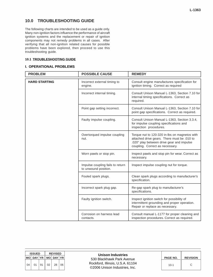
Unison Industries530 Blackhawk Park Avenue
Rockford, Illinois, U.S.A. 61104©2006 Unison Industries, Inc.
ISSUED
MO DAY YR
04 01 91
REVISED
MO DAY YR
02 28 06
PAGE NO. REVISION
C
L-1363
10-1
10.0 TROUBLESHOOTING GUIDE
The following charts are intended to be used as a guide only.Many non-ignition factors influence the performance of aircraftignition systems and the replacement or repair of ignitioncomponents may not remedy problems in all cases. Afterverifying that all non-ignition related causes for possibleproblems have been explored, then proceed to use thistroubleshooting guide.
10.1 TROUBLESHOOTING GUIDE
PROBLEM
HARD STARTING
POSSIBLE CAUSE
Incorrect external timing toengine.
Incorrect internal timing.
Point gap setting incorrect.
Faulty impulse coupling.
Overtorqued impulse couplingnut.
Worn pawls or stop pin.
Impulse coupling fails to returnto unwound position.
Fouled spark plugs.
Incorrect spark plug gap.
Faulty ignition switch.
Corrosion on harness leadcontacts.
REMEDY
Consult engine manufactures specification forignition timing. Correct as required
Consult Unison Manual L-1363, Section 7.10 forinternal timing specifications. Correct asrequired.
Consult Unison Manual L-1363, Section 7.10 forpoint gap specifications. Correct as required.
Consult Unison Manual L-1363, Section 3.3.4,for impulse coupling specifications andinspection procedures.
Torque nut to 120-320 in-lbs on magnetos withattached drive gears. There must be .010 to.020" play between drive gear and impulsecoupling. Correct as necessary.
Inspect pawls and stop pin for wear. Correct asnecessary.
Inspect impulse coupling nut for torque.
Clean spark plugs according to manufacturer’sspecification.
Re-gap spark plug to manufacturer’sspecifications.
Inspect ignition switch for possibility ofintermittent grounding and proper operation.Repair or replace as necessary.
Consult manual L-1177 for proper cleaning andinspection procedures. Correct as required.
I. OPERATIONAL PROBLEMS
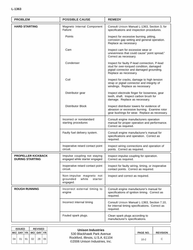
L-1363
Unison Industries530 Blackhawk Park Avenue
Rockford, Illinois, U.S.A. 61104©2006 Unison Industries, Inc.
ISSUED
MO DAY YR
04 01 91
REVISED
MO DAY YR
02 28 06
PAGE NO. REVISION
C
PROBLEM
HARD STARTING
PROPELLER KICKBACKDURING STARTING
ROUGH RUNNING
POSSIBLE CAUSE
Magneto Internal ComponentFailure:
Points
Cam
Condenser
Coil
Distributor gear
Distributor Block
Incorrect or nonstandardstarting procedures
Faulty fuel delivery system.
Inoperative retard contact pointcircuit.
Impulse coupling not stayingengaged while starter engaged
Inoperative retard contact pointcircuit.
Non-impulse magneto notgrounded while star terengaged.
Incorrect external timing toengine
Incorrect internal timing
Fouled spark plugs.
REMEDY
Consult Unison Manual L-1363, Section 3, forspecifications and inspection procedures.
Inspect for excessive burning, pitting,corrosion gap setting and general operation.Replace as necessary
Inspect cam for excessive wear orunevenness that could cause” point spread.”Correct as necessary.
Inspect for faulty P-lead connection, P-leadstud for over-torqued condition, damagedpigtail connector and damaged grounding.Replace as necessary.
Inspect for cracks, damage to high tensionstrap or pigtail connector and integrity ofwindings. Replace as necessary
Inspect electrode finger for looseness, gearteeth, shaft. Inspect carbon brush fordamage. Replace as necessary.
Inspect distributor towers for evidence ofabrasion or excessive burning. Examine rotorgear bushings for wear. Replace as necessary.
Consult engine manufacturers operationmanual for proper operation and performance.Correct as required.
Consult engine manufacturer’s manual forspecifications and operation. Correct asrequired.
Inspect wiring connections and operation ofpoints. Correct as required.
Inspect impulse coupling for operation.Correct as required.
Inspect for faulty wiring, timing, or inoperativecontact points. Correct as required.
Inspect and correct as required.
Consult engine manufacturer’s manual forspecifications of ignition timing. Correct asrequired.
Consult Unison Manual L-1363, Section 7.10,for internal timing specifications. Correct asrequired.
Clean spark plugs according tomanufacturer’s specifications.
10-2

Unison Industries530 Blackhawk Park Avenue
Rockford, Illinois, U.S.A. 61104©2006 Unison Industries, Inc.
ISSUED
MO DAY YR
04 01 91
REVISED
MO DAY YR
02 28 06
PAGE NO. REVISION
C
L-1363
10-3
PROBLEM
ROUGH RUNNING(cont.)
POSSIBLE CAUSE
Incorrect spark plug gap
Faulty spark plug.
Faulty ignition lead.
Faulty ignition switch
Magneto Internal ComponentFailure:
Points
Cam
Condenser
Coil
Distributor Gear
Distributor Block
Excessive heat.
Faulty fuel delivery system.
Faulty induction system
Faulty exhaust system.
REMEDY
Regap spark plug to manufacturer’sspecifications.
Test spark plug according to manufacturer’sspecifications.
Consult Unison Harness Maintenance ManualL-1499, for ignition lead troubleshootinginformation.
Inspect ignition switch for possibility ofintermittent grounding and proper operation.Repair of replace as necessary.
Consult Unison Manual L-1363, Section 3, forspecifications and inspection procedures.
Inspect for excessive burning, pitting,corrosion, gap setting and general operation.Replace as necessary.
Inspect cam for excessive wear orunevenness that could cause “cam spread.”Correct as necessary.
Inspect for faulty P-Lead connection, P-leadstud for overtorqued condition, damagedpigtail connector and damaged grounding.Replace as necessary.
Inspect for cracks, damage to high tensionstrap or pigtail connector and integrity ofwindings. Replace as necessary.
Inspect electrode finger for looseness, gearteeth, shaft. Inspect carbon brush fordamage. Replace as necessary.
Inspect distributor towers for evidence ofabrasion or excessive burning. Examine rotorgear bushings for wear. Replace as necessary.
Inspect baffling or cooling air duct. Correct asnecessary.
Consult engine manufacturer’s operationsmanual for proper operation and performance.Correct as required.
Inspect for leaks and faulty valve operation.Consult engine manufacturer’s specificationsfor proper operation and performance.
Inspect for obstructions in exhaust pipes andmufflers, faulty valve operation. Consultengine manufacturer’s specifications forproper operation and performance.
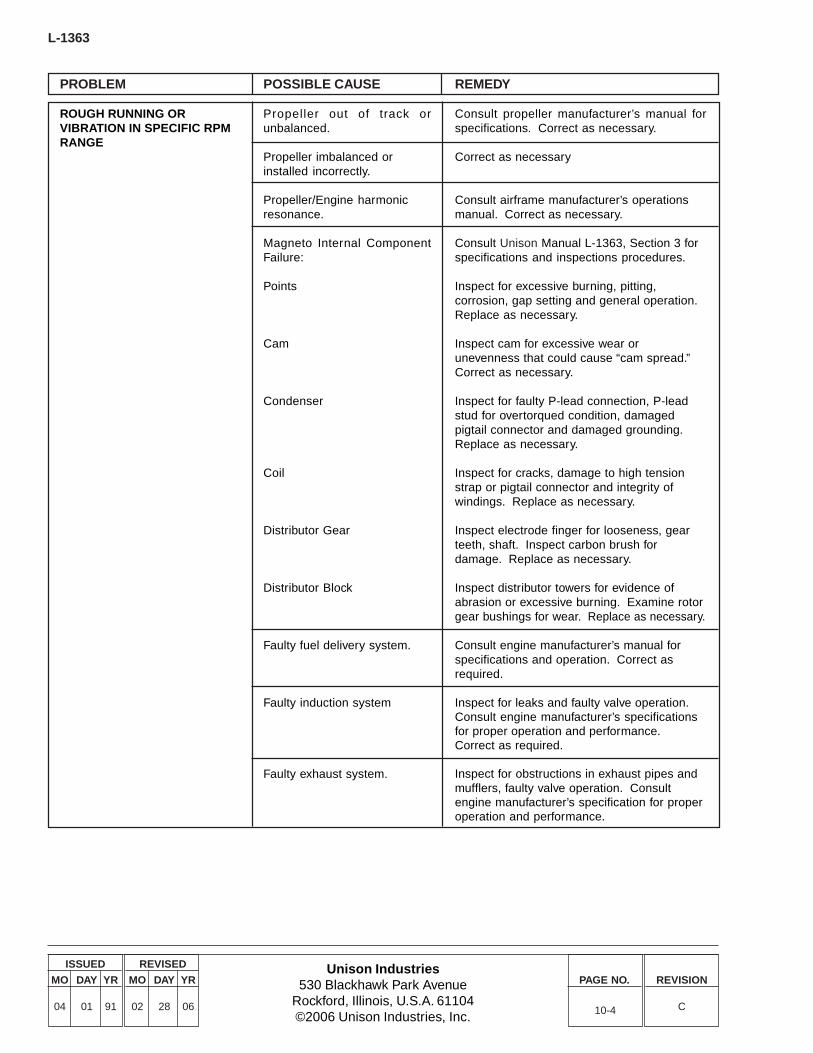
L-1363
Unison Industries530 Blackhawk Park Avenue
Rockford, Illinois, U.S.A. 61104©2006 Unison Industries, Inc.
ISSUED
MO DAY YR
04 01 91
REVISED
MO DAY YR
02 28 06
PAGE NO. REVISION
C10-4
PROBLEM
ROUGH RUNNING ORVIBRATION IN SPECIFIC RPMRANGE
POSSIBLE CAUSE
Propeller out of track orunbalanced.
Propeller imbalanced orinstalled incorrectly.
Propeller/Engine harmonicresonance.
Magneto Internal ComponentFailure:
Points
Cam
Condenser
Coil
Distributor Gear
Distributor Block
Faulty fuel delivery system.
Faulty induction system
Faulty exhaust system.
REMEDY
Consult propeller manufacturer’s manual forspecifications. Correct as necessary.
Correct as necessary
Consult airframe manufacturer’s operationsmanual. Correct as necessary.
Consult Unison Manual L-1363, Section 3 forspecifications and inspections procedures.
Inspect for excessive burning, pitting,corrosion, gap setting and general operation.Replace as necessary.
Inspect cam for excessive wear orunevenness that could cause “cam spread.”Correct as necessary.
Inspect for faulty P-lead connection, P-leadstud for overtorqued condition, damagedpigtail connector and damaged grounding.Replace as necessary.
Inspect for cracks, damage to high tensionstrap or pigtail connector and integrity ofwindings. Replace as necessary.
Inspect electrode finger for looseness, gearteeth, shaft. Inspect carbon brush fordamage. Replace as necessary.
Inspect distributor towers for evidence ofabrasion or excessive burning. Examine rotorgear bushings for wear. Replace as necessary.
Consult engine manufacturer’s manual forspecifications and operation. Correct asrequired.
Inspect for leaks and faulty valve operation.Consult engine manufacturer’s specificationsfor proper operation and performance.Correct as required.
Inspect for obstructions in exhaust pipes andmufflers, faulty valve operation. Consultengine manufacturer’s specification for properoperation and performance.

Unison Industries530 Blackhawk Park Avenue
Rockford, Illinois, U.S.A. 61104©2006 Unison Industries, Inc.
ISSUED
MO DAY YR
04 01 91
REVISED
MO DAY YR
02 28 06
PAGE NO. REVISION
C
L-1363
10-5
PROBLEM
EXCESSIVE RPM DROPDURING MAGNETO CHECK
MAGNETO WILL NOT FIRE
MAGNETO “HOT”
POWER LOSS
POSSIBLE CAUSE
Incorrect external timing toengine.
Incorrect internal timing.
Fouled spark plugs.
Incorrect spark plug gap.
Faulty spark plug.
Faulty tachometer.
Faulty ignition lead.
Corrosion on harness leadcontacts.
Faulty ignition switch.
Faulty condenser.
Point gap setting incorrect.
Retard contact point circuitinoperative.
Faulty ignition switch.
Broken “P” lead wire.
Incorrect external timing toengine.
Faulty Tachometer
REMEDY
Consult engine manufacturer’s manual forspecifications of ignition timing. Correct asnecessary.
Consult Unison Manual L-1363, Section 7.10,for internal timing specifications. Correct asrequired.
Clean spark plugs according to manufacturer’sspecifications.
Re-gap spark plug to manufacturer’sspecifications.
Test spark plug according to manufacturer’sspecifications
Confirm tachometer accuracy at RPM wheremagneto drop noted. Correct as necessary
Consult Unison Harness Maintenance ManualL-1499 for ignition lead troubleshootinginformation. Correct as required
Consult Unison Harness Maintenance ManualL-1499 for proper cleaning and inspectionprocedures. Correct as required.
Inspect ignition switch for possibility ofintermittent grounding and proper operation.Repair or replace as necessary
Consult Unison Manual L-1363, Section 3.3.7.Inspect for faulty P-lead connection, brokenP-lead stud, damaged pigtail connector, anddamaged grounding. Replace as necessary.
Consult Unison Manual L-1363, Section 7.10,for point cap specifications. Correct asrequired.
Inspect and correct as required.
Inspect ignition switch for possibility ofintermittent grounding and proper operation.Repair or replace as necessary.
Repair as necessary.
Consult engine manufacturer’s manual forspecifications of ignition timing. Correct asrequired.
Consult engine manufacturer’s manual forspecifications of ignition timing. Correct asrequired.

L-1363
Unison Industries530 Blackhawk Park Avenue
Rockford, Illinois, U.S.A. 61104©2006 Unison Industries, Inc.
ISSUED
MO DAY YR
04 01 91
REVISED
MO DAY YR
02 28 06
PAGE NO. REVISION
C10-6
PROBLEM
MOUNTING FLANGE BROKEN
POINTS BURNEDEXCESSIVELY
HIGH TENSION LEAD ON COILWORN OR BURNED THROUGH
COIL CRACKED OR ARCING INCASE
ELECTRODE FINGER LOOSEON DISTRIBUTOR GEAR
DISTRIBUTOR BLOCKTOWERS SCORED OREXCESSIVELY BURNED
DISTRIBUTOR GEARBUSHINGS EXCESSIVELYWORN
BEARING BAR BURNED
POSSIBLE CAUSE
Hold down clamp over torqued.
Hold down clamps torquedunevenly.
Magneto gasket residue onaccessory case mounting pad.
Faulty condenser.
Improper spark plug gap.
Fouled spark plug.
Excessive heat.
Improper tension between hightension lead and carbon brush.
Faulty coil.
Improper spark plug gap.
Fouled spark plug.
Faulty spark plug
Excessive heat
Timing pin wedged betweenelectrode and distributor blockduring timing process.
Electrode finger contactingtowers.
Improper lubrication of bushing.
Carbon tracking due toexcessive carbon brush wear.
REMEDY
Torque hold-down clamps to 190-220 in-lbs.
When magneto is reinstalled, be sure clampsare tightened with even pressure.
Be sure mounting face is free of gasket residue.
Consult Unison Manual L-1363, Section 3.3.7,for testing procedure. Replace as necessary.
Re-gap plugs according to manufacturer’sspecifications.
Clean spark plug according to manufacturer’sspecifications.
Inspect baffling or cooling air duct. Correct asnecessary.
Consult Unison Manual L-1363, Section 7.7, forhigh tension lead loading specifications.
Consult Unison Manual L-1363, Section 3.3.5,for specifications and inspection procedures.Replace as necessary.
Re-gap spark plug to manufacturer’sspecifications.
Clean spark plug according to manufacturer’sspecifications.
Inspect spark plug according to manufacturer’sspecifications.
Inspect baffling or cooling air duct. Correct asnecessary.
Consult Unison Manual L-1363 for proper timingprocedures. Replace block and gear assembly.
Inspect and replace as necessary.
Consult Unison Manual L-1363, Section 3.3.8,for proper maintenance procedures.
Consult Unison Manual L-1363, Section 7.7, forhigh tension lead loading specifications.
II. PHYSICAL DAMAGE
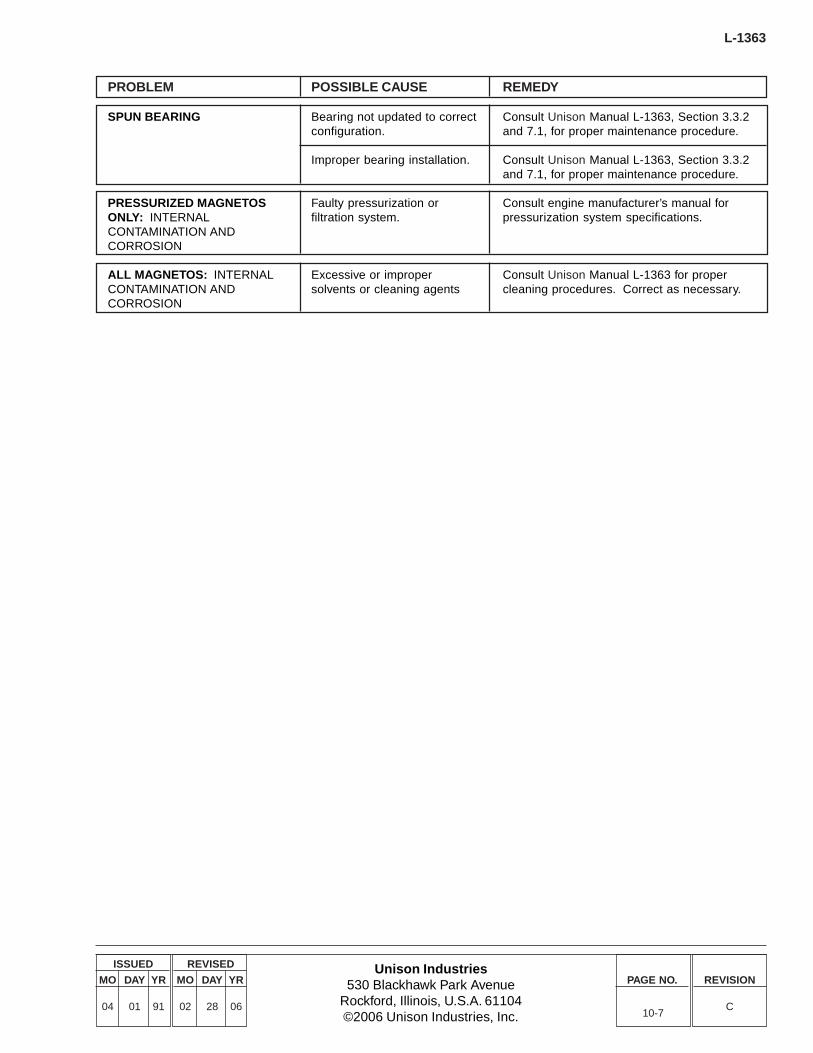
Unison Industries530 Blackhawk Park Avenue
Rockford, Illinois, U.S.A. 61104©2006 Unison Industries, Inc.
ISSUED
MO DAY YR
04 01 91
REVISED
MO DAY YR
02 28 06
PAGE NO. REVISION
C
L-1363
10-7
PROBLEM
SPUN BEARING
PRESSURIZED MAGNETOSONLY: INTERNALCONTAMINATION ANDCORROSION
ALL MAGNETOS: INTERNALCONTAMINATION ANDCORROSION
POSSIBLE CAUSE
Bearing not updated to correctconfiguration.
Improper bearing installation.
Faulty pressurization orfiltration system.
Excessive or impropersolvents or cleaning agents
REMEDY
Consult Unison Manual L-1363, Section 3.3.2and 7.1, for proper maintenance procedure.
Consult Unison Manual L-1363, Section 3.3.2and 7.1, for proper maintenance procedure.
Consult engine manufacturer’s manual forpressurization system specifications.
Consult Unison Manual L-1363 for propercleaning procedures. Correct as necessary.

THIS PAGE LEFT BLANK INTENTIONALLY.

Unison Industries530 Blackhawk Park Avenue
Rockford, Illinois, U.S.A. 61104©2006 Unison Industries, Inc.
ISSUED
MO DAY YR
04 01 91
REVISED
MO DAY YR
02 28 06
PAGE NO. REVISION
C
L-1363
T-1
TABLE ONE4300 SERIES OVERHAUL PARTS
REPLACEMENT LIST
The following parts must be replaced at overhaul. Additionalparts may require replacement depending on conditions asdetermined during magneto inspection. Install only UnisonReplacement Parts.
Use only genuine Unison manufactured parts obtained fromUnison approved sources. Genuine Unison parts areproduced and inspected under rigorous procedures to insureairworthiness and suitability in Slick magnetos. Partspurchased from sources other than Unison Industries, eventhough outwardly identical in appearance may not have hadthe required tests and inspections performed, may be differentin fabrication techniques and materials, and may bedangerous when installed in a Slick magneto. Salvagedmagneto parts, reworked parts obtained from non-Unisonapproved sources, or parts the service history of which isunknown or cannot be authenticated, may have beensubjected to unacceptable stresses or temperatures, or haveother hidden damage, not discernible through routine visualor usual nondestructive testing techniques. This may renderservice work with this par t, even though originallymanufactured by Unison Industries, unsuitable or unsafe foruse in a Slick magneto. Unison Industries expressly disclaimsany responsibility for malfunctions, failures, damage or injurycaused by use of non-Unison approved parts.
Slick magnetos are engineered to that mechanical parts wearat a balanced rate. Consistent and complimentary wearpatterns establish the recommended maintenance intervalsdefined in Unison service literature, therefore used, serviceworn parts should never be used to troubleshoot or repair amagneto, not should original parts be replaced by usedservice worn parts on magnetos being returned to service.Further, non-Unison manufactured parts may wear at unevenand different rates than original Unison manufactured parts,making Unison service literature an inappropriate guide toproper maintenance. Parts not manufactured by UnisonIndustries, even if FAA/PMA Approved may not fit or operatelike original Unison manufactured parts. FAA testing of PMAparts does not require operation on an engine or flight testsand does not require the test duration to exceed themaintenance intervals called out in Unison literature. Forthese reasons, used service worn parts or par ts notmanufactured by Unison Industries may adversely affectmagneto reliability in ways not anticipated by Unison Industriesand its service literature.
Description Qty
Condenser 1Double Sealed Bearing 1Bearing Cap Assembly 1Coil 1Impulse Coupling 1Oil Seal 1Contact Point Kit 1Rotor Gear 1Distributor Block & Gear 1
Reference Table Two “Parts Listing” for correct part numberfor a specified model magneto
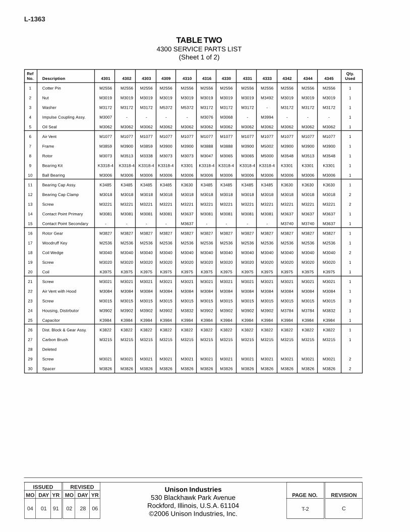
L-1363
Unison Industries530 Blackhawk Park Avenue
Rockford, Illinois, U.S.A. 61104©2006 Unison Industries, Inc.
ISSUED
MO DAY YR
04 01 91
REVISED
MO DAY YR
02 28 06
PAGE NO. REVISION
CT-2
TABLE TWO4300 SERVICE PARTS LIST
(Sheet 1 of 2)
Ref Qty.No. Description 4301 4302 4303 4309 4310 4316 4330 4331 4333 4342 4344 4345 Used
1 Cotter Pin M2556 M2556 M2556 M2556 M2556 M2556 M2556 M2556 M2556 M2556 M2556 M2556 1
2 Nut M3019 M3019 M3019 M3019 M3019 M3019 M3019 M3019 M3492 M3019 M3019 M3019 1
3 Washer M3172 M3172 M3172 M5372 M5372 M3172 M3172 M3172 - M3172 M3172 M3172 1
4 Impulse Coupling Assy. M3007 - - - - M3076 M3068 - M3994 - - - 1
5 Oil Seal M3062 M3062 M3062 M3062 M3062 M3062 M3062 M3062 M3062 M3062 M3062 M3062 1
6 Air Vent M1077 M1077 M1077 M1077 M1077 M1077 M1077 M1077 M1077 M1077 M1077 M1077 1
7 Frame M3859 M3900 M3859 M3900 M3900 M3888 M3888 M3900 M5002 M3900 M3900 M3900 1
8 Rotor M3073 M3513 M3338 M3073 M3073 M3047 M3065 M3065 M5000 M3548 M3513 M3548 1
9 Bearing Kit K3318-4 K3318-4 K3318-4 K3318-4 K3301 K3318-4 K3318-4 K3318-4 K3318-4 K3301 K3301 K3301 1
10 Ball Bearing M3006 M3006 M3006 M3006 M3006 M3006 M3006 M3006 M3006 M3006 M3006 M3006 1
11 Bearing Cap Assy. K3485 K3485 K3485 K3485 K3630 K3485 K3485 K3485 K3485 K3630 K3630 K3630 1
12 Bearing Cap Clamp M3018 M3018 M3018 M3018 M3018 M3018 M3018 M3018 M3018 M3018 M3018 M3018 2
13 Screw M3221 M3221 M3221 M3221 M3221 M3221 M3221 M3221 M3221 M3221 M3221 M3221 2
14 Contact Point Primary M3081 M3081 M3081 M3081 M3637 M3081 M3081 M3081 M3081 M3637 M3637 M3637 1
15 Contact Point Secondary - - - - M3637 - - - - M3740 M3740 M3637 1
16 Rotor Gear M3827 M3827 M3827 M3827 M3827 M3827 M3827 M3827 M3827 M3827 M3827 M3827 1
17 Woodruff Key M2536 M2536 M2536 M2536 M2536 M2536 M2536 M2536 M2536 M2536 M2536 M2536 1
18 Coil Wedge M3040 M3040 M3040 M3040 M3040 M3040 M3040 M3040 M3040 M3040 M3040 M3040 2
19 Screw M3020 M3020 M3020 M3020 M3020 M3020 M3020 M3020 M3020 M3020 M3020 M3020 1
20 Coil K3975 K3975 K3975 K3975 K3975 K3975 K3975 K3975 K3975 K3975 K3975 K3975 1
21 Screw M3021 M3021 M3021 M3021 M3021 M3021 M3021 M3021 M3021 M3021 M3021 M3021 1
22 Air Vent with Hood M3084 M3084 M3084 M3084 M3084 M3084 M3084 M3084 M3084 M3084 M3084 M3084 1
23 Screw M3015 M3015 M3015 M3015 M3015 M3015 M3015 M3015 M3015 M3015 M3015 M3015 3
24 Housing, Distirbutor M3902 M3902 M3902 M3902 M3832 M3902 M3902 M3902 M3902 M3784 M3784 M3832 1
25 Capacitor K3984 K3984 K3984 K3984 K3984 K3984 K3984 K3984 K3984 K3984 K3984 K3984 1
26 Dist. Block & Gear Assy. K3822 K3822 K3822 K3822 K3822 K3822 K3822 K3822 K3822 K3822 K3822 K3822 1
27 Carbon Brush M3215 M3215 M3215 M3215 M3215 M3215 M3215 M3215 M3215 M3215 M3215 M3215 1
28 Deleted
29 Screw M3021 M3021 M3021 M3021 M3021 M3021 M3021 M3021 M3021 M3021 M3021 M3021 2
30 Spacer M3826 M3826 M3826 M3826 M3826 M3826 M3826 M3826 M3826 M3826 M3826 M3826 2
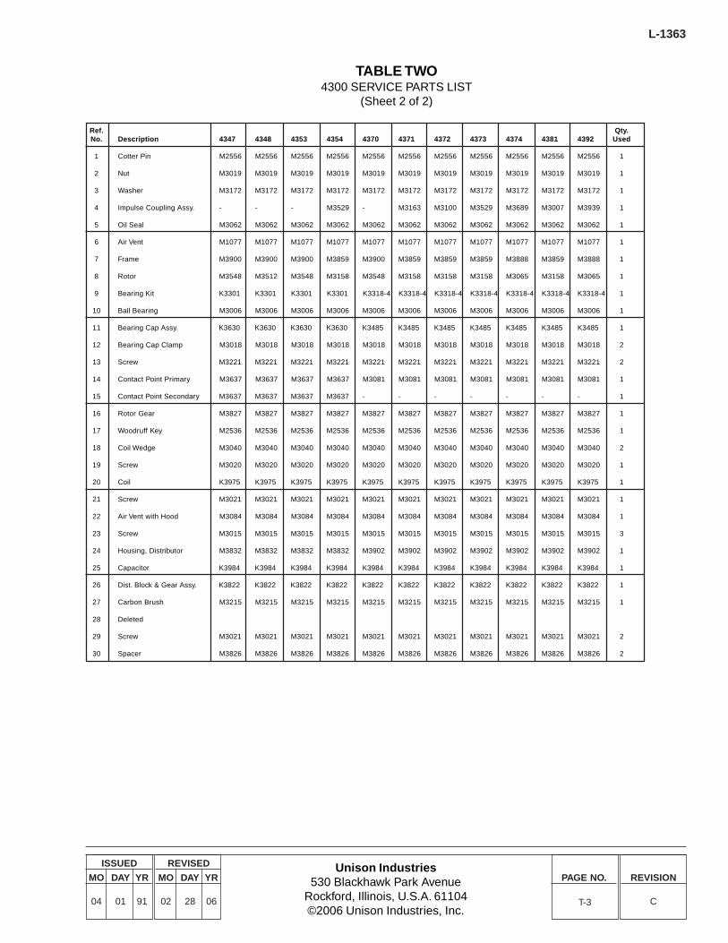
Unison Industries530 Blackhawk Park Avenue
Rockford, Illinois, U.S.A. 61104©2006 Unison Industries, Inc.
ISSUED
MO DAY YR
04 01 91
REVISED
MO DAY YR
02 28 06
PAGE NO. REVISION
C
L-1363
T-3
TABLE TWO4300 SERVICE PARTS LIST
(Sheet 2 of 2)
Ref. Qty.No. Description 4347 4348 4353 4354 4370 4371 4372 4373 4374 4381 4392 Used
1 Cotter Pin M2556 M2556 M2556 M2556 M2556 M2556 M2556 M2556 M2556 M2556 M2556 1
2 Nut M3019 M3019 M3019 M3019 M3019 M3019 M3019 M3019 M3019 M3019 M3019 1
3 Washer M3172 M3172 M3172 M3172 M3172 M3172 M3172 M3172 M3172 M3172 M3172 1
4 Impulse Coupling Assy. - - - M3529 - M3163 M3100 M3529 M3689 M3007 M3939 1
5 Oil Seal M3062 M3062 M3062 M3062 M3062 M3062 M3062 M3062 M3062 M3062 M3062 1
6 Air Vent M1077 M1077 M1077 M1077 M1077 M1077 M1077 M1077 M1077 M1077 M1077 1
7 Frame M3900 M3900 M3900 M3859 M3900 M3859 M3859 M3859 M3888 M3859 M3888 1
8 Rotor M3548 M3512 M3548 M3158 M3548 M3158 M3158 M3158 M3065 M3158 M3065 1
9 Bearing Kit K3301 K3301 K3301 K3301 K3318-4 K3318-4 K3318-4 K3318-4 K3318-4 K3318-4 K3318-4 1
10 Ball Bearing M3006 M3006 M3006 M3006 M3006 M3006 M3006 M3006 M3006 M3006 M3006 1
11 Bearing Cap Assy. K3630 K3630 K3630 K3630 K3485 K3485 K3485 K3485 K3485 K3485 K3485 1
12 Bearing Cap Clamp M3018 M3018 M3018 M3018 M3018 M3018 M3018 M3018 M3018 M3018 M3018 2
13 Screw M3221 M3221 M3221 M3221 M3221 M3221 M3221 M3221 M3221 M3221 M3221 2
14 Contact Point Primary M3637 M3637 M3637 M3637 M3081 M3081 M3081 M3081 M3081 M3081 M3081 1
15 Contact Point Secondary M3637 M3637 M3637 M3637 - - - - - - - 1
16 Rotor Gear M3827 M3827 M3827 M3827 M3827 M3827 M3827 M3827 M3827 M3827 M3827 1
17 Woodruff Key M2536 M2536 M2536 M2536 M2536 M2536 M2536 M2536 M2536 M2536 M2536 1
18 Coil Wedge M3040 M3040 M3040 M3040 M3040 M3040 M3040 M3040 M3040 M3040 M3040 2
19 Screw M3020 M3020 M3020 M3020 M3020 M3020 M3020 M3020 M3020 M3020 M3020 1
20 Coil K3975 K3975 K3975 K3975 K3975 K3975 K3975 K3975 K3975 K3975 K3975 1
21 Screw M3021 M3021 M3021 M3021 M3021 M3021 M3021 M3021 M3021 M3021 M3021 1
22 Air Vent with Hood M3084 M3084 M3084 M3084 M3084 M3084 M3084 M3084 M3084 M3084 M3084 1
23 Screw M3015 M3015 M3015 M3015 M3015 M3015 M3015 M3015 M3015 M3015 M3015 3
24 Housing, Distributor M3832 M3832 M3832 M3832 M3902 M3902 M3902 M3902 M3902 M3902 M3902 1
25 Capacitor K3984 K3984 K3984 K3984 K3984 K3984 K3984 K3984 K3984 K3984 K3984 1
26 Dist. Block & Gear Assy. K3822 K3822 K3822 K3822 K3822 K3822 K3822 K3822 K3822 K3822 K3822 1
27 Carbon Brush M3215 M3215 M3215 M3215 M3215 M3215 M3215 M3215 M3215 M3215 M3215 1
28 Deleted
29 Screw M3021 M3021 M3021 M3021 M3021 M3021 M3021 M3021 M3021 M3021 M3021 2
30 Spacer M3826 M3826 M3826 M3826 M3826 M3826 M3826 M3826 M3826 M3826 M3826 2
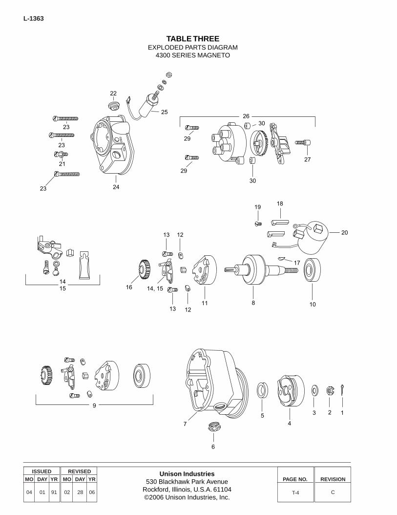
L-1363
Unison Industries530 Blackhawk Park Avenue
Rockford, Illinois, U.S.A. 61104©2006 Unison Industries, Inc.
ISSUED
MO DAY YR
04 01 91
REVISED
MO DAY YR
02 28 06
PAGE NO. REVISION
CT-4
TABLE THREEEXPLODED PARTS DIAGRAM
4300 SERIES MAGNETO
23
23
21
23
22
25
24
29
29
30
27
30
13 12
16 14, 15
13 1211 8 10
1918
20
17
7
6
54
3 2 1
GN
D
26
9
1415
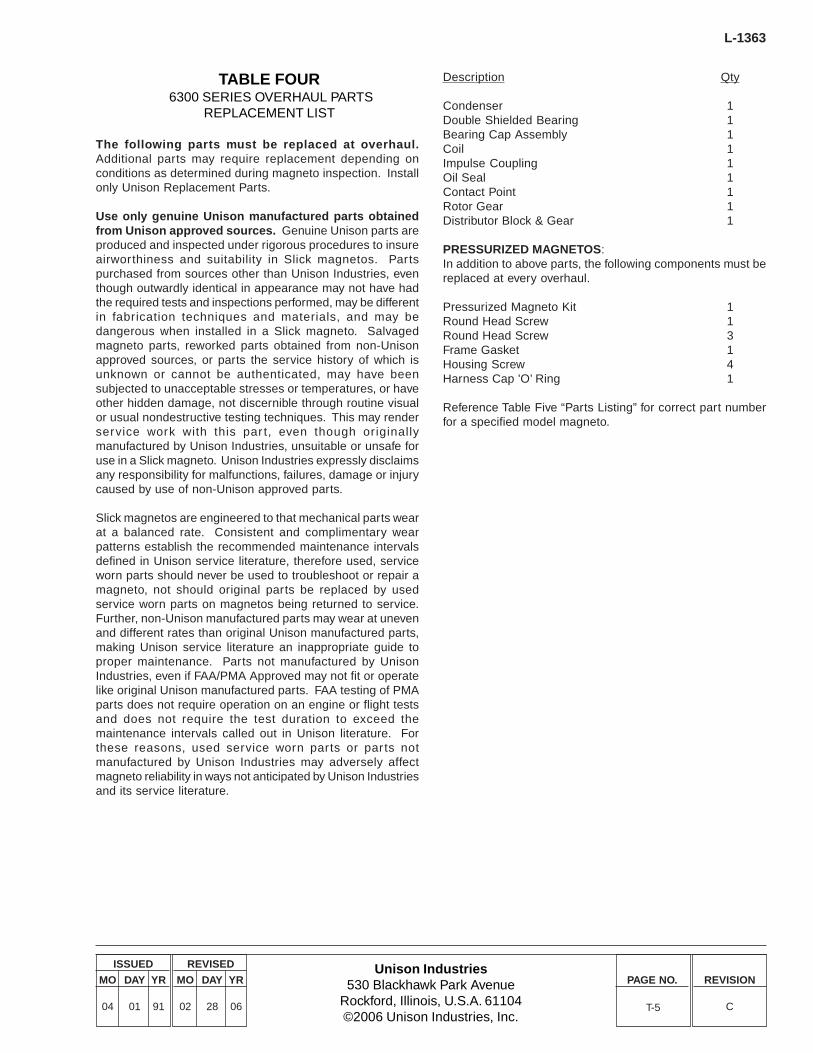
Unison Industries530 Blackhawk Park Avenue
Rockford, Illinois, U.S.A. 61104©2006 Unison Industries, Inc.
ISSUED
MO DAY YR
04 01 91
REVISED
MO DAY YR
02 28 06
PAGE NO. REVISION
C
L-1363
TABLE FOUR 6300 SERIES OVERHAUL PARTS
REPLACEMENT LIST
The following parts must be replaced at overhaul.Additional parts may require replacement depending onconditions as determined during magneto inspection. Installonly Unison Replacement Parts.
Use only genuine Unison manufactured parts obtainedfrom Unison approved sources. Genuine Unison parts areproduced and inspected under rigorous procedures to insureairworthiness and suitability in Slick magnetos. Partspurchased from sources other than Unison Industries, eventhough outwardly identical in appearance may not have hadthe required tests and inspections performed, may be differentin fabrication techniques and materials, and may bedangerous when installed in a Slick magneto. Salvagedmagneto parts, reworked parts obtained from non-Unisonapproved sources, or parts the service history of which isunknown or cannot be authenticated, may have beensubjected to unacceptable stresses or temperatures, or haveother hidden damage, not discernible through routine visualor usual nondestructive testing techniques. This may renderservice work with this par t, even though originallymanufactured by Unison Industries, unsuitable or unsafe foruse in a Slick magneto. Unison Industries expressly disclaimsany responsibility for malfunctions, failures, damage or injurycaused by use of non-Unison approved parts.
Slick magnetos are engineered to that mechanical parts wearat a balanced rate. Consistent and complimentary wearpatterns establish the recommended maintenance intervalsdefined in Unison service literature, therefore used, serviceworn parts should never be used to troubleshoot or repair amagneto, not should original parts be replaced by usedservice worn parts on magnetos being returned to service.Further, non-Unison manufactured parts may wear at unevenand different rates than original Unison manufactured parts,making Unison service literature an inappropriate guide toproper maintenance. Parts not manufactured by UnisonIndustries, even if FAA/PMA Approved may not fit or operatelike original Unison manufactured parts. FAA testing of PMAparts does not require operation on an engine or flight testsand does not require the test duration to exceed themaintenance intervals called out in Unison literature. Forthese reasons, used service worn parts or par ts notmanufactured by Unison Industries may adversely affectmagneto reliability in ways not anticipated by Unison Industriesand its service literature.
Description Qty
Condenser 1Double Shielded Bearing 1Bearing Cap Assembly 1Coil 1Impulse Coupling 1Oil Seal 1Contact Point 1Rotor Gear 1Distributor Block & Gear 1
PRESSURIZED MAGNETOS:In addition to above parts, the following components must bereplaced at every overhaul.
Pressurized Magneto Kit 1Round Head Screw 1Round Head Screw 3Frame Gasket 1Housing Screw 4Harness Cap 'O’ Ring 1
Reference Table Five “Parts Listing” for correct part numberfor a specified model magneto.
T-5
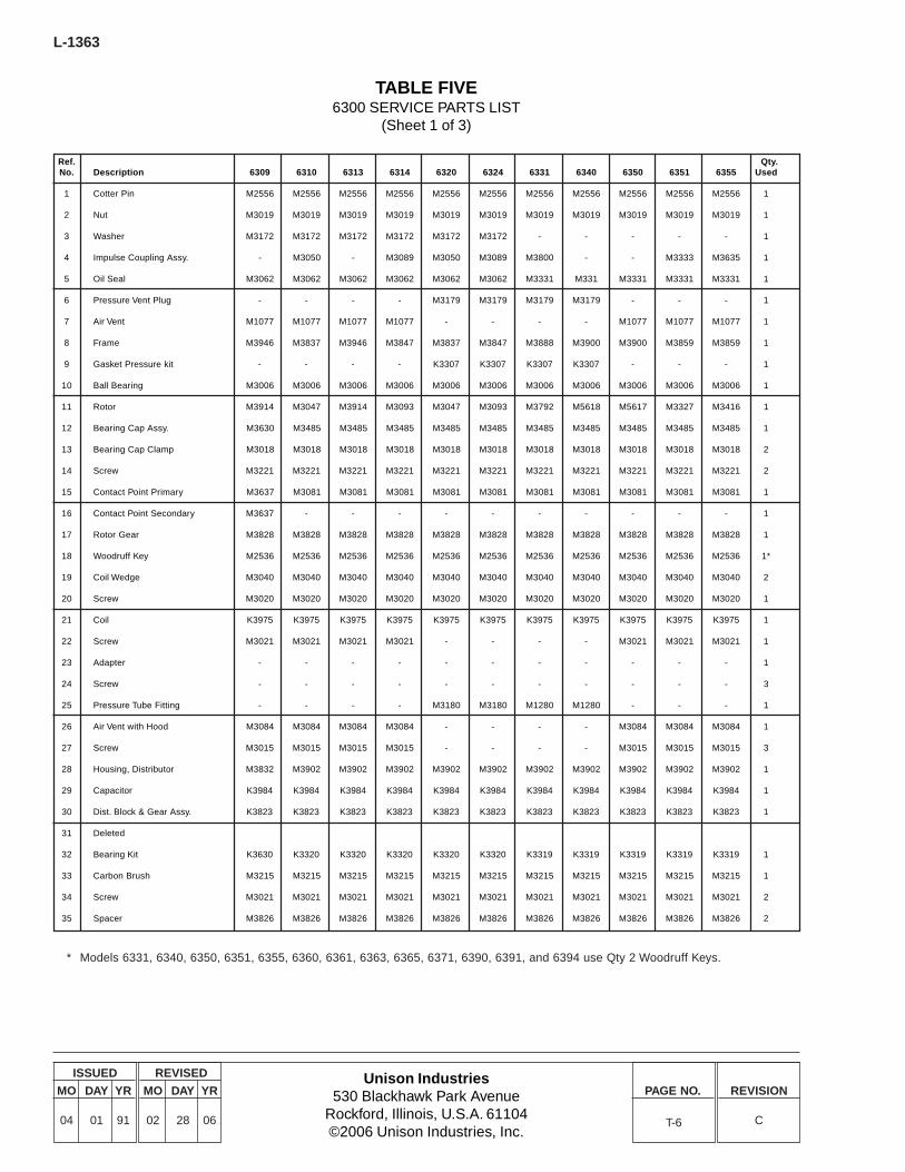
L-1363
Unison Industries530 Blackhawk Park Avenue
Rockford, Illinois, U.S.A. 61104©2006 Unison Industries, Inc.
ISSUED
MO DAY YR
04 01 91
REVISED
MO DAY YR
02 28 06
PAGE NO. REVISION
CT-6
TABLE FIVE6300 SERVICE PARTS LIST
(Sheet 1 of 3)
Ref. Qty.No. Description 6309 6310 6313 6314 6320 6324 6331 6340 6350 6351 6355 Used
1 Cotter Pin M2556 M2556 M2556 M2556 M2556 M2556 M2556 M2556 M2556 M2556 M2556 1
2 Nut M3019 M3019 M3019 M3019 M3019 M3019 M3019 M3019 M3019 M3019 M3019 1
3 Washer M3172 M3172 M3172 M3172 M3172 M3172 - - - - - 1
4 Impulse Coupling Assy. - M3050 - M3089 M3050 M3089 M3800 - - M3333 M3635 1
5 Oil Seal M3062 M3062 M3062 M3062 M3062 M3062 M3331 M331 M3331 M3331 M3331 1
6 Pressure Vent Plug - - - - M3179 M3179 M3179 M3179 - - - 1
7 Air Vent M1077 M1077 M1077 M1077 - - - - M1077 M1077 M1077 1
8 Frame M3946 M3837 M3946 M3847 M3837 M3847 M3888 M3900 M3900 M3859 M3859 1
9 Gasket Pressure kit - - - - K3307 K3307 K3307 K3307 - - - 1
10 Ball Bearing M3006 M3006 M3006 M3006 M3006 M3006 M3006 M3006 M3006 M3006 M3006 1
11 Rotor M3914 M3047 M3914 M3093 M3047 M3093 M3792 M5618 M5617 M3327 M3416 1
12 Bearing Cap Assy. M3630 M3485 M3485 M3485 M3485 M3485 M3485 M3485 M3485 M3485 M3485 1
13 Bearing Cap Clamp M3018 M3018 M3018 M3018 M3018 M3018 M3018 M3018 M3018 M3018 M3018 2
14 Screw M3221 M3221 M3221 M3221 M3221 M3221 M3221 M3221 M3221 M3221 M3221 2
15 Contact Point Primary M3637 M3081 M3081 M3081 M3081 M3081 M3081 M3081 M3081 M3081 M3081 1
16 Contact Point Secondary M3637 - - - - - - - - - - 1
17 Rotor Gear M3828 M3828 M3828 M3828 M3828 M3828 M3828 M3828 M3828 M3828 M3828 1
18 Woodruff Key M2536 M2536 M2536 M2536 M2536 M2536 M2536 M2536 M2536 M2536 M2536 1*
19 Coil Wedge M3040 M3040 M3040 M3040 M3040 M3040 M3040 M3040 M3040 M3040 M3040 2
20 Screw M3020 M3020 M3020 M3020 M3020 M3020 M3020 M3020 M3020 M3020 M3020 1
21 Coil K3975 K3975 K3975 K3975 K3975 K3975 K3975 K3975 K3975 K3975 K3975 1
22 Screw M3021 M3021 M3021 M3021 - - - - M3021 M3021 M3021 1
23 Adapter - - - - - - - - - - - 1
24 Screw - - - - - - - - - - - 3
25 Pressure Tube Fitting - - - - M3180 M3180 M1280 M1280 - - - 1
26 Air Vent with Hood M3084 M3084 M3084 M3084 - - - - M3084 M3084 M3084 1
27 Screw M3015 M3015 M3015 M3015 - - - - M3015 M3015 M3015 3
28 Housing, Distributor M3832 M3902 M3902 M3902 M3902 M3902 M3902 M3902 M3902 M3902 M3902 1
29 Capacitor K3984 K3984 K3984 K3984 K3984 K3984 K3984 K3984 K3984 K3984 K3984 1
30 Dist. Block & Gear Assy. K3823 K3823 K3823 K3823 K3823 K3823 K3823 K3823 K3823 K3823 K3823 1
31 Deleted
32 Bearing Kit K3630 K3320 K3320 K3320 K3320 K3320 K3319 K3319 K3319 K3319 K3319 1
33 Carbon Brush M3215 M3215 M3215 M3215 M3215 M3215 M3215 M3215 M3215 M3215 M3215 1
34 Screw M3021 M3021 M3021 M3021 M3021 M3021 M3021 M3021 M3021 M3021 M3021 2
35 Spacer M3826 M3826 M3826 M3826 M3826 M3826 M3826 M3826 M3826 M3826 M3826 2
* Models 6331, 6340, 6350, 6351, 6355, 6360, 6361, 6363, 6365, 6371, 6390, 6391, and 6394 use Qty 2 Woodruff Keys.

Unison Industries530 Blackhawk Park Avenue
Rockford, Illinois, U.S.A. 61104©2006 Unison Industries, Inc.
ISSUED
MO DAY YR
04 01 91
REVISED
MO DAY YR
02 28 06
PAGE NO. REVISION
C
L-1363
T-7
TABLE FIVE6300 SERVICE PARTS LIST
(Sheet 2 of 3)
Ref. Qty.No. Description 6360 6361 6362 6363 6364 6365 6367 6371 6377 6379 6380 Used
1 Cotter Pin M2556 M2556 M2556 M2556 M2556 M2556 M2556 M2556 M2556 M2556 M2556 1
2 Nut M3019 M3019 M3019 M3019 M3492 M3019 M3492 M3019 M3019 M3019 M3019 1
3 Washer - - M3172 - - - - - M3172 M3172 M3172 1
4 Impulse Coupling Assy. - M3333 M3050 - M3590 - M3524 - M5014 M5020 M3050 1
5 Oil Seal M3331 M3331 M3062 M3331 M3062 M3331 M3062 M3331 M3062 M3062 M3062 1
6 Pressure Vent Plug M3179 M3179 - M3179 - M3179 - - - - - 1
7 Air Vent - - M1077 - M1077 - M1077 M1077 M1077 M1077 M1968 1
8 Frame M3900 M3859 M3837 M3900 M3853 M3900 M3856 M3900 M3859 M3859 M3850 1
9 Gasket Pressure kit K3307 K3307 - K3307 - K3307 - - - - - 1
10 Ball Bearing M3006 M3006 M3006 M3006 M3006 M3006 M3006 M3006 M3006 M3006 M3006 1
11 Rotor M5617 M3327 M3047 M5617 M3496 M5617 M3499 M5617 M5015 M5015 M3047 1
12 Bearing Cap Assy. M3485 M3485 M3485 M3630 M3485 M3630 M3485 M3630 M3485 M3485 M3485 1
13 Bearing Cap Clamp M3018 M3018 M3018 M3018 M3018 M3018 M3018 M3018 M3018 M3018 M3018 2
14 Screw M3221 M3221 M3221 M3221 M3221 M3221 M3221 M3221 M3221 M3221 M3221 2
15 Contact Point Primary M3081 M3081 M3081 M3637 M3081 M3637 M3081 M3637 M3081 M3081 M3081 1
16 Contact Point Secondary - - - M3637 - M3637 - M3637 - - - 1
17 Rotor Gear M3828 M3828 M3828 M3828 M3828 M3828 M3828 M3828 M3828 M3828 M3828 1
18 Woodruff Key M2536 M2536 M2536 M2536 M2536 M2536 M2536 M2536 M2536 M2536 M2536 1*
19 Coil Wedge M3040 M3040 M3040 M3040 M3040 M3040 M3040 M3040 M3040 M3040 M3040 2
20 Screw M3020 M3020 M3020 M3020 M3020 M3020 M3020 M3020 M3020 M3020 M3020 1
21 Coil K3975 K3975 K3975 K3975 K3975 K3975 K3975 K3975 K3975 K3975 K3975 1
22 Screw - - M3021 - M3021 - M3021 M3021 M3021 M3021 M3021 1
23 Adapter - - M3154 - - - - - - - - 1
24 Screw - - M3125 - - - - - - - - 3
25 Pressure Tube Fitting M1280 M1280 - M1280 - M1280 - - - - - 1
26 Air Vent with Hood - - M3084 - M3084 - M3084 M3084 M3084 M3084 M3084 1
27 Screw - - M3015 - M3015 - M3015 M3015 M3015 M3015 M3015 3
28 Housing, Distributor M3902 M3902 M3902 M3832 M3902 M3832 M3902 M3902 M3902 M3902 M3902 1
29 Capacitor K3984 K3984 K3984 K3984 K3984 K3984 K3984 K3984 K3984 K3984 K3984 1
30 Dist. Block & Gear Assy. K3823 K3823 K3823 K3823 K3823 K3823 K3823 K3823 K3823 K3823 K3823 1
31 Deleted
32 Bearing Kit K3319 K3319 K3320 K3302 K3320 K3302 K3320 K3302 K3320 K3320 K3320 1
33 Carbon Brush M3215 M3215 M3215 M3215 M3215 M3215 M3215 M3215 M3215 M3215 M3215 1
34 Screw M3021 M3021 M3021 M3021 M3021 M3021 M3021 M3021 M3021 M3021 M3021 2
35 Spacer M3826 M3826 M3826 M3826 M3826 M3826 M3826 M3826 M3826 M3826 M3826 2
* Models 6331, 6340, 6350, 6351, 6355, 6360, 6361, 6363, 6365, 6371, 6390, 6391, and 6394 use Qty 2 Woodruff Keys.
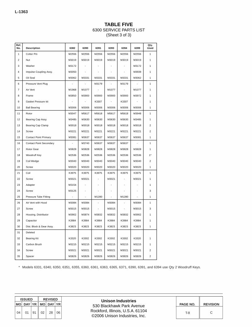
L-1363
Unison Industries530 Blackhawk Park Avenue
Rockford, Illinois, U.S.A. 61104©2006 Unison Industries, Inc.
ISSUED
MO DAY YR
04 01 91
REVISED
MO DAY YR
02 28 06
PAGE NO. REVISION
CT-8
TABLE FIVE6300 SERVICE PARTS LIST
(Sheet 3 of 3)
Ref. Qty.No. Description 6382 6390 6391 6393 6394 6399 Used
1 Cotter Pin M2556 M2556 M2556 M2556 M2556 M2556 1
2 Nut M3019 M3019 M3019 M3019 M3019 M3019 1
3 Washer M3172 - - - - M3172 1
4 Impulse Coupling Assy. M3050 - - - - M3939 1
5 Oil Seal M3062 M3331 M3331 M3331 M3331 M3062 1
6 Pressure Vent Plug - - M3179 - M3179 - 1
7 Air Vent M1968 M1077 - M1077 - M1077 1
8 Frame M3850 M3900 M3900 M3900 M3900 M3972 1
9 Gasket Pressure kit - - K3307 - K3307 - 1
10 Ball Bearing M3006 M3006 M3006 M3006 M3006 M3006 1
11 Rotor M3047 M5617 M5618 M5617 M5618 M3948 1
12 Bearing Cap Assy. M3485 M3630 M3630 M3630 M3630 M3485 1
13 Bearing Cap Clamp M3018 M3018 M3018 M3018 M3018 M3018 2
14 Screw M3221 M3221 M3221 M3221 M3221 M3221 2
15 Contact Point Primary M3081 M3637 M3637 M3637 M3637 M3081 1
16 Contact Point Secondary - M3740 M3637 M3637 M3637 - 1
17 Rotor Gear M3828 M3828 M3828 M3828 M3828 M3828 1
18 Woodruff Key M2536 M2536 M2536 M2536 M2536 M2536 1*
19 Coil Wedge M3040 M3040 M3040 M3040 M3040 M3040 2
20 Screw M3020 M3020 M3020 M3020 M3020 M3020 1
21 Coil K3975 K3975 K3975 K3975 K3975 K3975 1
22 Screw M3021 M3021 - M3021 - M3021 1
23 Adapter M3154 - - - - - 1
24 Screw M3125 - - - - - 3
25 Pressure Tube Fitting - - M1280 - M1280 - 1
26 Air Vent with Hood M3084 M3084 - M3084 - M3084 1
27 Screw M3015 M3015 - M3015 - M3015 3
28 Housing, Distributor M3902 M3874 M3832 M3832 M3832 M3902 1
29 Capacitor K3984 K3984 K3984 K3984 K3984 K3984 1
30 Dist. Block & Gear Assy. K3823 K3823 K3823 K3823 K3823 K3823 1
31 Deleted
32 Bearing Kit K3320 K3302 K3302 K3302 K3302 K3320 1
33 Carbon Brush M3215 M3215 M3215 M3215 M3215 M3215 1
34 Screw M3021 M3021 M3021 M3021 M3021 M3021 2
35 Spacer M3826 M3826 M3826 M3826 M3826 M3826 2
* Models 6331, 6340, 6350, 6351, 6355, 6360, 6361, 6363, 6365, 6371, 6390, 6391, and 6394 use Qty 2 Woodruff Keys.
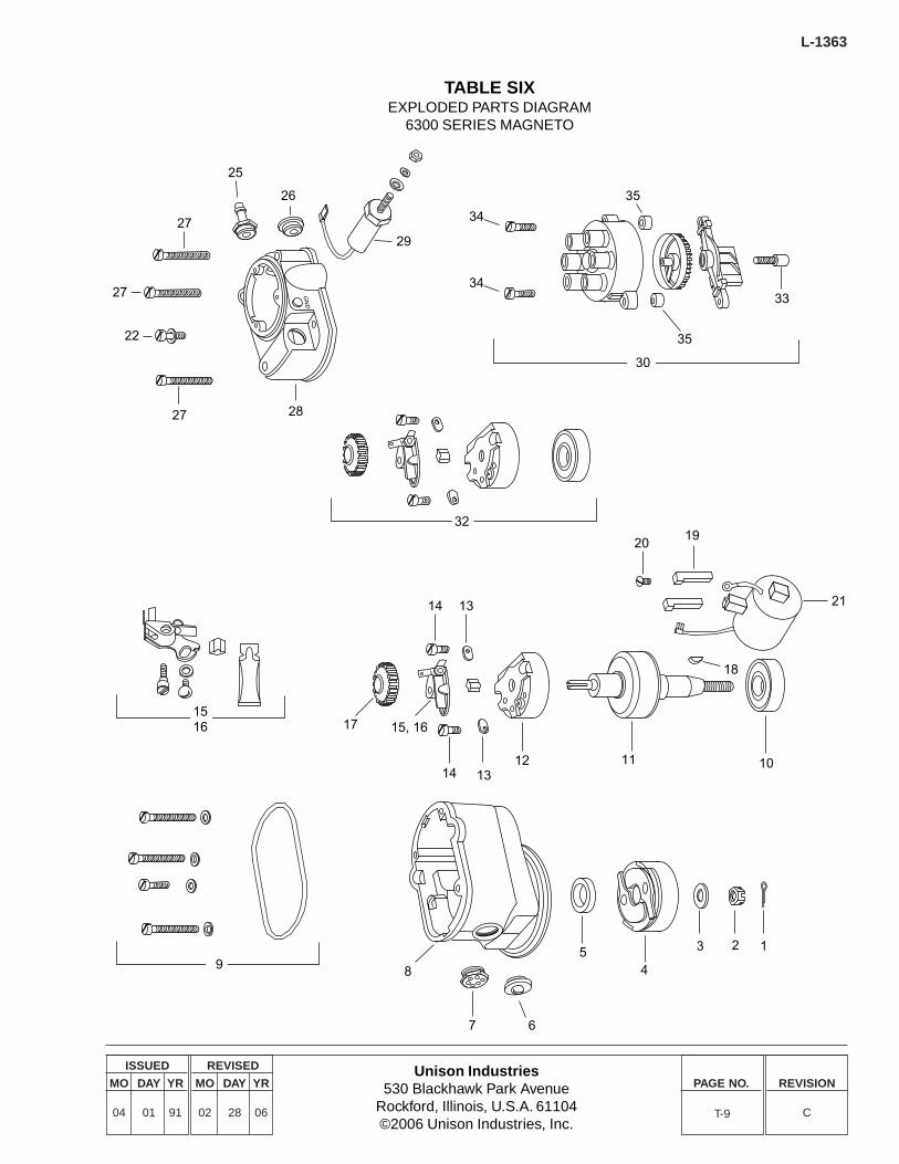
Unison Industries530 Blackhawk Park Avenue
Rockford, Illinois, U.S.A. 61104©2006 Unison Industries, Inc.
ISSUED
MO DAY YR
04 01 91
REVISED
MO DAY YR
02 28 06
PAGE NO. REVISION
C
L-1363
T-9
TABLE SIXEXPLODED PARTS DIAGRAM
6300 SERIES MAGNETO
27
27
22
27 28
25
26
29
GN
D
14 13
17 15, 16
14 1312 11 10
2019
21
18
8
7
54
3 2 1
32
1516
6
34
35
33
35
30
34
9
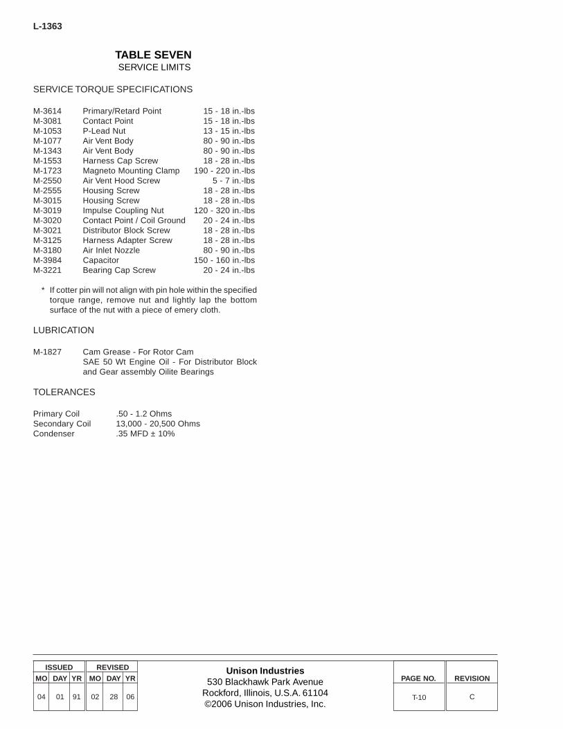
L-1363
Unison Industries530 Blackhawk Park Avenue
Rockford, Illinois, U.S.A. 61104©2006 Unison Industries, Inc.
ISSUED
MO DAY YR
04 01 91
REVISED
MO DAY YR
02 28 06
PAGE NO. REVISION
C
TABLE SEVEN SERVICE LIMITS
SERVICE TORQUE SPECIFICATIONS
M-3614 Primary/Retard Point 15 - 18 in.-lbsM-3081 Contact Point 15 - 18 in.-lbsM-1053 P-Lead Nut 13 - 15 in.-lbsM-1077 Air Vent Body 80 - 90 in.-lbsM-1343 Air Vent Body 80 - 90 in.-lbsM-1553 Harness Cap Screw 18 - 28 in.-lbsM-1723 Magneto Mounting Clamp 190 - 220 in.-lbsM-2550 Air Vent Hood Screw 5 - 7 in.-lbsM-2555 Housing Screw 18 - 28 in.-lbsM-3015 Housing Screw 18 - 28 in.-lbsM-3019 Impulse Coupling Nut 120 - 320 in.-lbsM-3020 Contact Point / Coil Ground 20 - 24 in.-lbsM-3021 Distributor Block Screw 18 - 28 in.-lbsM-3125 Harness Adapter Screw 18 - 28 in.-lbsM-3180 Air Inlet Nozzle 80 - 90 in.-lbsM-3984 Capacitor 150 - 160 in.-lbsM-3221 Bearing Cap Screw 20 - 24 in.-lbs
* If cotter pin will not align with pin hole within the specifiedtorque range, remove nut and lightly lap the bottomsurface of the nut with a piece of emery cloth.
LUBRICATION
M-1827 Cam Grease - For Rotor CamSAE 50 Wt Engine Oil - For Distributor Blockand Gear assembly Oilite Bearings
TOLERANCES
Primary Coil .50 - 1.2 OhmsSecondary Coil 13,000 - 20,500 OhmsCondenser .35 MFD ± 10%
T-10

THIS PAGE LEFT BLANK INTENTIONALLY.

Unison Industries530 Blackhawk Park AvenueRockford, Illinois, U.S.A. 61104Telephone: 815-965-4700FAX: 815-965-2457http:\\www.unisonindustries.com
Form L-1363CUnison and Slick are registered trademarks of Unison Industries©2005 Unison Industries